JP5725552B2 - Wireless communication apparatus, communication system, communication processing method, and program - Google Patents
Wireless communication apparatus, communication system, communication processing method, and program Download PDFInfo
- Publication number
- JP5725552B2 JP5725552B2 JP2011182661A JP2011182661A JP5725552B2 JP 5725552 B2 JP5725552 B2 JP 5725552B2 JP 2011182661 A JP2011182661 A JP 2011182661A JP 2011182661 A JP2011182661 A JP 2011182661A JP 5725552 B2 JP5725552 B2 JP 5725552B2
- Authority
- JP
- Japan
- Prior art keywords
- wireless communication
- transmission
- packet
- feature amount
- communication device
- Prior art date
- Legal status (The legal status is an assumption and is not a legal conclusion. Google has not performed a legal analysis and makes no representation as to the accuracy of the status listed.)
- Active
Links
- 238000004891 communication Methods 0.000 title claims description 231
- 238000003672 processing method Methods 0.000 title claims description 12
- 230000005540 biological transmission Effects 0.000 claims description 347
- 238000012545 processing Methods 0.000 claims description 77
- 238000000034 method Methods 0.000 claims description 60
- 238000005259 measurement Methods 0.000 claims description 41
- 238000001514 detection method Methods 0.000 claims description 39
- 230000008569 process Effects 0.000 claims description 24
- 230000008859 change Effects 0.000 claims description 4
- 238000012360 testing method Methods 0.000 description 23
- 230000002452 interceptive effect Effects 0.000 description 17
- 230000000694 effects Effects 0.000 description 13
- 101100172132 Mus musculus Eif3a gene Proteins 0.000 description 12
- 230000006870 function Effects 0.000 description 11
- 238000010586 diagram Methods 0.000 description 10
- 230000004044 response Effects 0.000 description 4
- 230000006866 deterioration Effects 0.000 description 2
- 238000009434 installation Methods 0.000 description 2
- 239000004065 semiconductor Substances 0.000 description 2
- 230000035945 sensitivity Effects 0.000 description 2
- 108700026140 MAC combination Proteins 0.000 description 1
- 230000003044 adaptive effect Effects 0.000 description 1
- 230000006399 behavior Effects 0.000 description 1
- 238000005516 engineering process Methods 0.000 description 1
- 230000006872 improvement Effects 0.000 description 1
- 239000004973 liquid crystal related substance Substances 0.000 description 1
- 230000009467 reduction Effects 0.000 description 1
- 230000008054 signal transmission Effects 0.000 description 1
Images


Landscapes
- Mobile Radio Communication Systems (AREA)
Description
本発明は、無線通信装置、通信システム、通信処理方法、およびその方法を無線通信装置に実行させるためのプログラムに関する。 The present invention relates to a wireless communication device, a communication system, a communication processing method, and a program for causing a wireless communication device to execute the method.
現在、ISM(Industrial,Sience,Medical)帯と呼ばれる免許不要で利用可能な無線周波数帯を使用する、複数の無線方式が規格化されている。具体的には、無線LAN(Local Area Network)として一般的なIEEE 802.11や、センサーネットワークでの利用が有望視されているIEEE 802.15.4といった無線通信規格が存在し、これら無線通信規格は、今後も増加し、またそれを使用する無線端末の数も、爆発的に増加することが見込まれている。 Currently, a plurality of radio systems using a radio frequency band that is available without a license, called an ISM (Industrial, Science, Medical) band, are standardized. Specifically, there are wireless communication standards such as IEEE 802.11, which is general as a wireless LAN (Local Area Network), and IEEE 802.15.4, which is expected to be used in sensor networks. The number of standards will continue to increase, and the number of wireless terminals that use them is expected to increase explosively.
上記のような無線通信規格は、お互いの無線信号が衝突するのを回避するため、TDMA(Time Division Multiple Access)、FDMA(Frequency Division Multiple Access)、CDMA(Code Division Multiple Access)、CSMA/CA(Carrier Sense Mulitple Access with Collision Avoidance:衝突回避機能付き搬送波感知多重アクセス)などの多重チャネルアクセス方式を備えている。 In order to avoid collision of radio signals with each other, wireless communication standards such as those described above may be used for TDMA (Time Division Multiple Access), FDMA (Frequency Division Multiple Access), CDMA (Code Division Multiple Access), and CDMA (Code Division Multiple Access / CS). A multi-channel access scheme such as Carrier Sense Multiple Access with Collision Avoidance (carrier sense multiple access with collision avoidance function) is provided.
ISM帯を使用する代表的な通信方式であるIEEE 802.11や、省電力無線通信の代表例であるIEEE 802.15.4では、チャネルアクセス方式として、CSMA/CA方式を用いている。 In IEEE 802.11, which is a typical communication method using the ISM band, and IEEE 802.15.4, which is a typical example of power saving wireless communication, the CSMA / CA method is used as a channel access method.
CSMA/CA方式とは、パケット送信に先立ち、バックオフと呼ばれるランダムな時間で送信を待機し、Preamble DetectionやEnergy Detectionといわれる手法で送信チャネルが使用されているか否かを確認するCCA(Channel Clear Assessment)を実施し、チャネルが未使用であればパケット送信を行う手法である。 Prior to packet transmission, the CSMA / CA method waits for transmission at a random time called back-off and confirms whether or not a transmission channel is being used by a method called “Preamble Detection” or “Energy Detection”. (Assessment) is performed, and a packet is transmitted if the channel is not used.
しかしながら、無線端末毎に、CCAによって他端末の送信を検出することができる範囲は異なる。 However, the range in which transmission of other terminals can be detected by CCA differs for each wireless terminal.
1つ目の理由として、CSMA/CAの詳細な動作が無線通信規格毎に異なることが挙げられる。ここで言うCSMA/CAの詳細な動作とは、具体的には、CCAの実施タイミング、Energy Detectionの閾値やその実行時間、信号が検出された後のパケット送信待ちおよび再送の振る舞いである。 The first reason is that the detailed operation of CSMA / CA differs for each wireless communication standard. The detailed operation of CSMA / CA here refers specifically to CCA implementation timing, energy detection threshold and execution time, and packet transmission waiting and retransmission behavior after a signal is detected.
2つ目の理由として、同一の無線通信規格を利用する端末同士であっても、信号受信性能の差が存在することが挙げられる。信号受信性能の差は、具体的には、無線通信アンテナの利得、無線通信装置自身のノイズ排除能力、端末の設置場所周囲の環境などにより生じる。 The second reason is that there is a difference in signal reception performance even between terminals using the same wireless communication standard. Specifically, the difference in signal reception performance is caused by the gain of the wireless communication antenna, the noise rejection capability of the wireless communication device itself, the environment around the terminal installation location, and the like.
図15は、無線端末毎に他の無線端末が送信する信号を検出可能な範囲(信号検出圏)が異なることを示す一例である。図15に示す破線の円は、その円内に他の無線端末が存在すれば、その無線信号を検出可能な範囲を示す。図15では、送信端末Bは送信端末Aの検出圏内に位置しているが、送信端末Aは送信端末Bの検出圏外に位置しており、2つの端末間で信号検出圏が非対称な状態である。 FIG. 15 is an example showing that a range (signal detection area) in which a signal transmitted by another wireless terminal can be detected is different for each wireless terminal. A broken-line circle shown in FIG. 15 indicates a range in which the wireless signal can be detected if another wireless terminal exists in the circle. In FIG. 15, the transmission terminal B is located within the detection area of the transmission terminal A, but the transmission terminal A is located outside the detection area of the transmission terminal B, and the signal detection area is asymmetric between the two terminals. is there.
図15に示すように、送信端末Aおよび送信端末Bの信号検出圏が異なっていると、送信端末Aは送信端末Bが送信した信号を検出できるが、送信端末Bは送信端末Aが送信した信号を検出できなくなる状態がある。このような状態を、以下では「CCA非対称状態」と称する。CCA非対称状態において、図15における送信端末Aに相当する端末を被干渉側端末と称し、図15における送信端末Bに相当する端末を与干渉側端末と称する。 As shown in FIG. 15, when the signal detection areas of the transmission terminal A and the transmission terminal B are different, the transmission terminal A can detect the signal transmitted by the transmission terminal B, but the transmission terminal B transmits the transmission terminal A. There is a state where the signal cannot be detected. Hereinafter, such a state is referred to as a “CCA asymmetric state”. In the CCA asymmetric state, a terminal corresponding to transmitting terminal A in FIG. 15 is referred to as an interfered terminal, and a terminal corresponding to transmitting terminal B in FIG. 15 is referred to as an interfering side terminal.
CCA非対称状態では、与干渉側端末の送信量が増加した場合に、被干渉側端末の送信が一方的に抑えられるという問題がある。 In the CCA asymmetric state, there is a problem that transmission of the interfered side terminal is unilaterally suppressed when the transmission amount of the interfering side terminal increases.
さらに、CCA非対称状態では、被干渉側端末が送信中に与干渉側端末が送信を行うことで、パケット衝突が発生するという問題がある。 Further, in the CCA asymmetric state, there is a problem that packet collision occurs when the interfering side terminal performs transmission while the interfered side terminal transmits.
さらに、上記の問題から、通信効率が低下するという問題点がある。 Furthermore, there is a problem that the communication efficiency is lowered due to the above problem.
通信効率が低下した原因を判定する手法として、特許文献1では、送信間隔とRSS(Received Signal Strength:受信信号強度)を用いた手法を提案している。 As a method for determining the cause of the reduction in communication efficiency, Patent Document 1 proposes a method using a transmission interval and RSS (Received Signal Strength).
特許文献1に開示された技術では、自端末が送信したパケットの送信間隔と、相手端末から送信されたパケットのRSSを、事前に決定した閾値と比較し、その結果から通信効率の低下の原因を"送信端末数や送信パケット数の増加に伴う輻輳"または"電波伝搬環境の悪化による通信失敗"のどちらかであると判定する。 In the technique disclosed in Patent Document 1, the transmission interval of the packet transmitted from the own terminal and the RSS of the packet transmitted from the counterpart terminal are compared with a predetermined threshold, and the cause of the decrease in communication efficiency is determined from the result. Is determined to be either “congestion due to an increase in the number of transmission terminals or transmission packets” or “communication failure due to deterioration of radio wave propagation environment”.
原因が輻輳であると判定された場合は、自端末が送信するパケットの伝送レートを高くして短時間で送信することにより輻輳を回避し、電波環境の悪化が原因であると判定された場合、伝送レートを低くすることでノイズ耐性を向上させてパケットロスを回避する。 When it is determined that the cause is congestion, the congestion rate is avoided by increasing the transmission rate of packets sent by the terminal itself in a short time, and it is determined that the radio wave environment has deteriorated. By reducing the transmission rate, noise resistance is improved and packet loss is avoided.
また、非特許文献1では、「一方向隠れ端末問題」として、同一通信方式無線端末間でのCCA非対称状態の改善方法が論じられている。 Further, Non-Patent Document 1 discusses a method for improving the CCA asymmetric state between wireless terminals of the same communication method as the “one-way hidden terminal problem”.
特許文献1に開示された方法では、CCA非対称状態による通信効率の低下(以後、CCA非対称状態により生じる干渉と称する)は単純な送信パケット数の増加による輻輳であると判定される。そのため、伝送レートを高くし、短時間で送信が完了するように制御を行うが、既に伝送レートが規格上の上限値である場合は効果がない。さらに、CCA非対称状態においては、被干渉側が送信するパケットの伝送レートを高くし短時間で送信が完了するようにしても、与干渉側端末から被干渉側端末を検出できるようにはならないため、CCA非対称状態自体が改善されることはない。そのため、パケット衝突率は低下するが、通信効率については、被干渉側が伝送レートを高くしたことで空いた時間分を与干渉側の送信パケットが消費するため、大きな改善は望めない。 In the method disclosed in Patent Document 1, it is determined that a decrease in communication efficiency due to the CCA asymmetric state (hereinafter referred to as interference caused by the CCA asymmetric state) is congestion due to a simple increase in the number of transmitted packets. Therefore, control is performed so that the transmission rate is increased and transmission is completed in a short time, but there is no effect if the transmission rate is already the upper limit value in the standard. Furthermore, in the CCA asymmetric state, even if the transmission rate of the packet transmitted by the interfered side is increased and transmission is completed in a short time, the interfered side terminal cannot be detected from the interfering side terminal. The CCA asymmetric state itself is not improved. Therefore, although the packet collision rate is reduced, the communication efficiency is not expected to be greatly improved because the transmission packet on the interfering side consumes the time that has been freed by increasing the transmission rate on the interfered side.
ゆえに、CCA非対称状態により生じる干渉は単純な輻輳とは別の状態であることから、CCA非対称状態を検出しなければ、CCA非対称状態により生じる干渉を改善するのに適した対処を行うことはできない。 Therefore, since the interference caused by the CCA asymmetric state is different from simple congestion, it is not possible to take appropriate measures to improve the interference caused by the CCA asymmetric state unless the CCA asymmetric state is detected. .
非特許文献1では、CCA非対称状態の検出方法については言及されていない。また、非特許文献1において提案されている手法では、被干渉側および与干渉側の無線通信方式がIEEE 802.11方式を使用していることを前提としているため、被干渉側と与干渉側の無線通信方式が異なる通信方式であった場合、CCA非対称状態が改善されないばかりか、パケット衝突率が上昇する。 Non-Patent Document 1 does not mention a method for detecting a CCA asymmetric state. In the method proposed in Non-Patent Document 1, it is assumed that the wireless communication system on the interfered side and the interfering side uses the IEEE 802.11 system. If the wireless communication systems are different, the CCA asymmetric state is not improved, and the packet collision rate is increased.
具体的には、非特許文献1では、「一方向隠れ端末問題」の改善方法として、被干渉側端末に相当するSU(Secondary User)の最小バックオフ時間を制御する定数CW(Contention Window)minの値を小さくし、バックオフ時間を短くすることで、被干渉側端末の過剰な待ちを抑制させることを提案している。しかし、与干渉側端末に相当するPU(Primary User)の送信したパケットを保護するため、NAV(Network Allocation Vector)によりPUの送信したパケットにSUの送信したパケットが衝突しないようにしているが、例えば、PUがIEEE 802.15.4方式で通信を行い、SUがIEEE 802.11方式で通信を行うような場合、PUがNAVを設定することはできないため、PUが送信したデータパケットと、それに対する応答パケット(ACKパケット)の間に、SUがデータパケットを送信し、SUのデータパケットとPUの応答パケット(ACKパケット)が衝突する可能性が上昇してしまう。 Specifically, in Non-Patent Document 1, as a method of improving the “one-way hidden terminal problem”, a constant CW (Contention Window) min for controlling a minimum backoff time of an SU (Secondary User) corresponding to the interfered side terminal is used. It is proposed to reduce the excessive waiting of the interfered side terminal by reducing the value of and reducing the back-off time. However, in order to protect the packets transmitted by the PU (Primary User) corresponding to the interfering side terminal, the packets transmitted by the SU do not collide with the packets transmitted by the PU by NAV (Network Allocation Vector). For example, when the PU communicates with the IEEE 802.15.4 system and the SU communicates with the IEEE 802.11 system, since the PU cannot set the NAV, the data packet transmitted by the PU, During the response packet (ACK packet) to that, the SU transmits a data packet, and the possibility that the SU data packet and the PU response packet (ACK packet) collide with each other increases.
ゆえに、異なる無線通信方式間においてもCCA非対称状態を検出し、CCA非対称状態により生じる干渉を改善する必要がある。 Therefore, it is necessary to detect a CCA asymmetric state between different wireless communication schemes and to improve interference caused by the CCA asymmetric state.
本発明は上述したような技術が有する問題点を解決するためになされたものであり、CCA非対称状態を検出可能にした無線通信装置、通信システム、通信処理方法、およびその方法を無線通信装置に実行させるためのプログラムを提供することを目的とする。 The present invention has been made in order to solve the above-described problems of the technology, and a wireless communication device, a communication system, a communication processing method, and a method thereof capable of detecting a CCA asymmetric state are provided in the wireless communication device. The object is to provide a program for execution.
上記目的を達成するための本発明の無線通信装置は、
他の無線通信装置から送信されるパケットと同一チャネルでパケットを送信する際、パケットの衝突を回避する制御を行う無線通信処理部と、
前記他の無線通信装置がパケット送信を停止している状態における前記無線通信処理部のパケット送信処理の特徴量である第1の送信特徴量、ならびに自装置および前記他の無線通信装置がパケット送信を行う状態における前記無線通信処理部のパケット送信処理の特徴量である第2の送信特徴量を取得する送信特徴量測定部と、
前記第1および前記第2の送信特徴量に基づいて、前記他の無線通信装置が自装置の信号検出圏内に位置しているが、該他の無線通信装置の信号検出圏外に自装置が位置する状態である信号検出圏非対称状態であるか否かを判定する非対称状態判定部と、
を有する構成である。
In order to achieve the above object, a wireless communication apparatus of the present invention provides:
A wireless communication processing unit that performs control to avoid collision of packets when transmitting a packet on the same channel as a packet transmitted from another wireless communication device;
A first transmission feature amount which is a feature amount of packet transmission processing of the wireless communication processing unit in a state where the other wireless communication device stops packet transmission, and the own device and the other wireless communication device transmit packets. A transmission feature amount measurement unit that acquires a second transmission feature amount that is a feature amount of packet transmission processing of the wireless communication processing unit in a state of performing
Based on the first and second transmission feature quantities, the other wireless communication apparatus is located within the signal detection area of the own apparatus, but the own apparatus is located outside the signal detection area of the other wireless communication apparatus. An asymmetric state determination unit that determines whether or not the signal detection sphere is in an asymmetric state,
It is the structure which has.
また、本発明の通信システムは、
他の無線通信装置から送信されるパケットと同一チャネルでパケットを送信する際、パケットの衝突を回避する制御を行う無線通信処理部と、前記他の無線通信装置がパケット送信を停止している状態における前記無線通信処理部のパケット送信処理の特徴量である第1の送信特徴量、ならびに自装置および前記他の無線通信装置がパケット送信を行う状態における前記無線通信処理部のパケット送信処理の特徴量である第2の送信特徴量を取得する送信特徴量測定部とを含む無線通信装置と、
前記無線通信装置と通信可能に接続され、該無線通信装置から受信する前記第1および前記第2の送信特徴量に基づいて、前記他の無線通信装置が該無線通信装置の信号検出圏内に位置しているが、該他の無線通信装置の信号検出圏外に該無線通信装置が位置する状態であるか否かを判定する非対称状態判定部を含むゲートウェイ装置と、
を有する構成である。
The communication system of the present invention
When transmitting a packet on the same channel as a packet transmitted from another wireless communication device, a wireless communication processing unit that performs control to avoid packet collision, and the state in which the other wireless communication device has stopped packet transmission The first transmission feature amount that is the feature amount of the packet transmission processing of the wireless communication processing unit in FIG. 3 and the feature of the packet transmission processing of the wireless communication processing unit in a state where the own device and the other wireless communication device perform packet transmission A wireless communication device including a transmission feature amount measurement unit that acquires a second transmission feature amount that is a quantity;
Based on the first and second transmission feature quantities that are communicably connected to the wireless communication device and received from the wireless communication device, the other wireless communication device is located within a signal detection range of the wireless communication device. A gateway device including an asymmetric state determination unit that determines whether or not the wireless communication device is located outside the signal detection range of the other wireless communication device;
It is the structure which has.
また、本発明の通信処理方法は、他の無線通信装置から送信されるパケットと同一チャネルでパケットを送信する際、パケットの衝突を回避する制御を行う無線通信装置による通信処理方法であって、
前記他の無線通信装置がパケット送信を停止している状態における、自装置のパケット送信処理の特徴量である第1の送信特徴量を取得し、
自装置および前記他の無線通信装置がパケット送信を行う状態における、自装置のパケット送信処理の特徴量である第2の送信特徴量を取得し、
前記第1および前記第2の送信特徴量に基づいて、前記他の無線通信装置が自装置の信号検出圏内に位置しているが、該他の無線通信装置の信号検出圏外に自装置が位置する状態であるか否かを判定するものである。
The communication processing method of the present invention is a communication processing method by a wireless communication device that performs control to avoid collision of packets when transmitting a packet on the same channel as a packet transmitted from another wireless communication device,
Obtaining a first transmission feature amount that is a feature amount of packet transmission processing of the own device in a state where the other wireless communication device has stopped packet transmission;
Obtaining a second transmission feature amount that is a feature amount of packet transmission processing of the own device in a state where the own device and the other wireless communication device perform packet transmission;
Based on the first and second transmission feature quantities, the other wireless communication apparatus is located within the signal detection area of the own apparatus, but the own apparatus is located outside the signal detection area of the other wireless communication apparatus. It is judged whether it is in the state to do.
さらに、本発明のプログラムは、他の無線通信装置から送信されるパケットと同一チャネルでパケットを送信する際、パケットの衝突を回避する制御を行う無線通信装置に実行させるためのプログラムであって、
前記他の無線通信装置がパケット送信を停止している状態における、自装置のパケット送信処理の特徴量である第1の送信特徴量を取得し、
自装置および前記他の無線通信装置がパケット送信を行う状態における、自装置のパケット送信処理の特徴量である第2の送信特徴量を取得し、
前記第1および前記第2の送信特徴量に基づいて、前記他の無線通信装置が自装置の信号検出圏内に位置しているが、該他の無線通信装置の信号検出圏外に自装置が位置する状態であるか否かを判定する処理を前記無線通信装置に実行させるものである。
Furthermore, the program of the present invention is a program for causing a wireless communication device to perform control for avoiding packet collision when transmitting a packet on the same channel as a packet transmitted from another wireless communication device,
Obtaining a first transmission feature amount that is a feature amount of packet transmission processing of the own device in a state where the other wireless communication device has stopped packet transmission;
Obtaining a second transmission feature amount that is a feature amount of packet transmission processing of the own device in a state where the own device and the other wireless communication device perform packet transmission;
Based on the first and second transmission feature quantities, the other wireless communication apparatus is located within the signal detection area of the own apparatus, but the own apparatus is located outside the signal detection area of the other wireless communication apparatus. The wireless communication apparatus is caused to execute processing for determining whether or not the wireless communication device is in a state to be performed.
本発明によれば、CCA非対称状態を検出可能になるので、CCA非対称状態を改善するための対策を実行できる。 According to the present invention, the CCA asymmetric state can be detected, so that measures for improving the CCA asymmetric state can be executed.
本発明の無線通信装置の実施形態を説明する。以下に説明する実施形態では、被干渉側となる無線通信装置がIEEE 802.11方式で通信を行い、与干渉側となる無線通信装置がIEEE 802.15.4方式で通信を行う場合で説明するが、通信端末同士が互いの無線信号が衝突するのを回避して通信を行う方法であれば、他の通信方法であってもよい。 An embodiment of a wireless communication apparatus of the present invention will be described. In the embodiment described below, a case where a radio communication apparatus serving as an interfered side performs communication using the IEEE 802.11 system and a radio communication apparatus serving as an interfering side performs communication using the IEEE 802.15.4 system will be described. However, any other communication method may be used as long as the communication terminals communicate with each other while avoiding collision between the radio signals.
(第1の実施形態)
本実施形態の無線通信装置について説明する。本実施形態では、CSMA/CA方式でアクセス制御を行う無線通信装置をStation(STA)と表記する。
(First embodiment)
The wireless communication apparatus of this embodiment will be described. In the present embodiment, a wireless communication apparatus that performs access control using the CSMA / CA method is referred to as Station (STA).
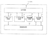
図1は、本実施形態の無線通信装置が被干渉無線機に相当する場合における通信システムの一構成例を示すブロック図である。 FIG. 1 is a block diagram illustrating a configuration example of a communication system when the wireless communication apparatus according to the present embodiment corresponds to an interfered radio device.
本実施形態において、STA111は、STA121が送信したパケットにより干渉を受け、CCA非対称状態を判定する被干渉無線機であるものとする。また、STA121は、STA111が送信したパケットをCCAにより検出することができず、CCA非対称状態になることで、STA111に対して干渉を与える与干渉無線機であるものとする。
In this embodiment, it is assumed that the
GW131は、STA111およびSTA121と通信可能であり、STA111とSTA121の間で通信を介助することが可能な無線通信ゲートウェイ装置である。
The
なお、本実施形態では、GW131における、STA111と通信するための無線通信機能と、STA121と通信するための無線通信機能は、物理的に1つの装置の場合で説明する。他の実施形態として、STA111と通信するための無線通信機能と、STA121と通信するための無線通信機能を、物理的に別の装置とし、その両者を無線または有線にて接続するようにしてもよい。
In the present embodiment, the wireless communication function for communicating with the
また、本実施形態では、同一の周波数帯を使用し、かつ、CSMA/CA方式によるチャネルアクセスを行うことを共通点とする、異なる無線通信方式を、STA111とSTA121のそれぞれが用いる場合で説明する。他の実施形態として、CSMA/CA方式によるチャネルアクセスを行う同一の無線通信方式を、STA111およびSTA121が用いる構成であってもよい。
Further, in the present embodiment, different wireless communication schemes using the same frequency band and having channel access by the CSMA / CA scheme in common will be described in the case where each of the
次に、CCA非対称状態の検出と改善を行う機能の構成について、図2を参照して説明する。図2は図1に示したSTA111の一構成例を示すブロック図である。
Next, the configuration of the function for detecting and improving the CCA asymmetric state will be described with reference to FIG. FIG. 2 is a block diagram showing a configuration example of the
図2に示すように、STA111は、無線通信処理部15と、送信特徴量測定部11と、通信特徴量記憶部12と、CCA非対称状態判定部13と、送信パラメタ制御部14と、全体制御部16とを有する。
As shown in FIG. 2, the
送信特徴量測定部11は、自装置の無線通信処理部15の送信状態を測定し、パケット送信処理に関する特徴量である送信特徴量を取得する。
The transmission feature amount measuring unit 11 measures the transmission state of the wireless
通信特徴量記憶部12は、送信特徴量測定部11にて取得された送信特徴量を記憶する。通信特徴量記憶部12は、例えば、不揮発性メモリである。
The communication feature
CCA非対称状態判定部13は、通信特徴量記憶部12に保存された送信特徴量から、送信状態の測定を実施した装置がCCA非対称状態であるか否かを判定する。
The CCA asymmetric
送信パラメタ制御部14は、CCA非対称状態判定部13が出力した判定結果と、状態が判定されたSTA111(送信状態の測定を行った無線通信装置に相当)の通信状態、それ以外の無線通信装置に相当するSTA121の通信状態、またはその両方から、状態が判定されたSTA111、STA121、またはその両方の送信制御に係わる諸パラメタを変更する。
The transmission
無線通信処理部15は、パケット送信を行う前に、CCAを行って送信チャネルが使用されているか否かを確認し、送信チャネルが未使用であれば、パケット送信を行う。また、無線通信処理部15は、送信特徴量測定部11が要求する送信状態情報を取得し、送信パラメタ制御部14の制御にしたがって送信パラメタを変更する。ここで、送信状態情報とは、無線通信処理部15がパケット送信を行う際の状態を示す情報を意味し、図5を参照して説明するパケット送信間隔の情報を含む。
Before performing packet transmission, the wireless
全体制御部16は、CCA非対称状態の検出および改善を実行するために、送信特徴量測定部11、通信特徴量記憶部12、および送信パラメタ制御部14を制御する。
The
なお、無線通信処理部15、送信特徴量測定部11、CCA非対称状態判定部13、送信パラメタ制御部14および全体制御部16の各部の構成は、例えば、それぞれの機能を実行するための回路が設けられた専用の半導体集積回路である。また、別の一例として、プログラムにしたがって処理を実行するCPU(Central Processing Unit)およびプログラムを保存するメモリを有する制御部(不図示)がSTA111に予め設けられ、CPUがプログラムを実行することで、無線通信処理部15、送信特徴量測定部11、CCA非対称状態判定部13、送信パラメタ制御部14および全体制御部16が仮想的に構成されてもよい。さらに、CPUがプログラムを実行することで仮想的に構成される対象は、無線通信処理部15、送信特徴量測定部11、CCA非対称状態判定部13、送信パラメタ制御部14および全体制御部16に限らず、これらのうちの一部であってもよい。
The configuration of each unit of the wireless
次に、図1に示したGW131の構成を、図3を参照して説明する。図3はGW131の一構成例を示すブロック図である。本実施形態では、CCA非対称状態の検出および改善に関連する構成について説明し、一般的な無線通信ゲートウェイとしての機能についての詳細な説明を省略する。
Next, the configuration of the
図3に示すように、GW131は、制御部31および記憶部32を有する。制御部31は、プログラムにしたがって処理を実行するCPU(不図示)と、プログラムを記憶するメモリ(不図示)とを有する。制御部31は、STA111およびSTA121のうち、一方の無線機がテストパケットをGW131に送信し、他方の無線機がパケットの送信を停止している基準状態で、一方の無線機から受信するテストパケットについて、テストパケット信号の長さ、平均送信待ち時間、および単位時間当たりの送信パケット数を含むテストパケット情報を記憶部32に記録する。制御部31は、STA111およびSTA121の無線機毎にテストパケット情報を記憶部32に保存する。そして、制御部31は、STA111およびSTA121のうち、一方の無線機から他方の無線機のテストパケット情報についての問い合わせがあると、他方の無線機のテストパケット情報を記憶部32から読み出し、読み出したテストパケット情報を問い合わせ元の無線機に通知する。
As illustrated in FIG. 3, the
なお、本実施形態では、図2に示すように、STA111が送信特徴量測定部11〜全体制御部16を有する構成の場合で説明するが、通信特徴量記憶部12、CCA非対称状態判定部13、送信パラメタ制御部14および全体制御部16は必ずしもSTA111に設けられている必要はなく、これらの構成が物理的に他の無線通信装置に設けられ、STA111が他の無線通信装置と何らかの通信回線で接続される構成であってもよい。
In the present embodiment, as illustrated in FIG. 2, the
例えば、STA111が送信特徴量測定部11および無線通信処理部15を備え、GW131が通信特徴量記憶部12、CCA非対称状態判定部13、送信パラメタ制御部14および全体制御部16を備えている場合が考えられる。また、STA111が送信特徴量測定部11、通信特徴量記憶部12および無線通信処理部15を備え、GW131がCCA非対称状態判定部13、送信パラメタ制御部14および全体制御部16を備えている場合が考えられる。さらに、STA111が送信特徴量測定部11、通信特徴量記憶部12、CCA非対称状態判定部13および無線通信処理部15を備え、GW131が送信パラメタ制御部14および全体制御部16を備えている場合が考えられる。
For example, when the
また、STA121がSTA111と同様な構成であってもよい。
The
次に、STA111が実行する、CCA非対称状態の検出と改善のための動作を説明する。
Next, operations for detecting and improving the CCA asymmetric state performed by the
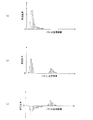
図4は本実施形態の通信処理方法の手順を示すフローチャートである。図5は送信パケットを説明するための図である。図6は本実施形態における、CCA非対称状態の検出方法を説明するためのヒストグラムである。 FIG. 4 is a flowchart showing the procedure of the communication processing method of the present embodiment. FIG. 5 is a diagram for explaining a transmission packet. FIG. 6 is a histogram for explaining the CCA asymmetric state detection method in this embodiment.
第1の処理として、CCA非対称状態でない場合における送信状態の特徴量を、基準状態の送信特徴量として取得する処理を実行する(ステップ201)。以下に、第1の処理について詳しく説明する。 As a first process, a process for acquiring a transmission state feature amount in a case where the CCA is not in an asymmetric state as a reference state transmission feature amount is executed (step 201). Hereinafter, the first process will be described in detail.
なお、本実施形態では、CCA非対称状態の判定精度向上のため、基準状態の送信特徴量を取得するために、パケットを実際に送信する場合で説明するが、パケット送信を実際に行わずに、基準状態の送信特徴量を理論値から求めるなどしてもよい。 In this embodiment, in order to improve the accuracy of determination of the CCA asymmetric state, a case will be described in which a packet is actually transmitted in order to acquire a transmission feature amount in a reference state. However, without actually performing packet transmission, The transmission feature amount in the reference state may be obtained from a theoretical value.
まず、STA121のパケット送信による測定への影響を防止するため、全体制御部16は、STA121に対して送信を禁止するように指示する。続いて、全体制御部16が、送信特徴量測定部11に対し、後述する送信特徴量の測定を実行させる。送信特徴量の測定が完了したら、全体制御部16はSTA121に対してパケット送信禁止の解除を通知する。
First, in order to prevent the influence of the packet transmission of the
続いて、送信特徴量測定部11の測定動作を、図5を参照して説明する。 Next, the measurement operation of the transmission feature quantity measurement unit 11 will be described with reference to FIG.
送信特徴量測定部11は、パケット長Ltpl[byte]のテストパケットを、送信処理アイドル時間Tspid[s]の間隔を空けて送信時間Ttrt[s]の間、送信するよう、無線通信処理部15に指示する。 The transmission feature amount measuring unit 11 transmits the test packet having the packet length Ltpl [byte] during the transmission time Ttrt [s] with an interval of the transmission processing idle time Tspid [s]. To instruct.
なお、図5中のパケット送信待機区間は、バックオフ時間およびチャネルビジーによる送信開始待ちを含む、無線通信処理部15がパケット送信処理を開始した時間から、実際に無線信号の送信が開始される時間までの区間である。
Note that the packet transmission standby period in FIG. 5 actually starts the transmission of the radio signal from the time when the wireless
このとき、STA111が送信するテストパケットのパケット長Ltpl[byte]および送信処理アイドル時間Tspid[s]は、送信時間Ttrt[s]の間、一定の値であればよいが、本実施形態では、測定精度を高めるため、パケット長Ltplは、無線通信処理部15が許す最大長とし、送信処理アイドル時間Tspidは無線通信処理部15が許す最小値とする。
At this time, the packet length Ltpl [byte] and the transmission processing idle time Tspid [s] of the test packet transmitted by the
全体制御部16より指示を受けた送信特徴量測定部11は、前回のパケット送信終了時間から送信処理アイドル時間Tspid[s]の間隔をおいて、繰り返しテストパケットを生成し、無線通信処理部15にGW131宛てにテストパケットを送信させる。無線通信処理部15はパケット送信の都度、パケット送信間隔の情報を送信特徴量測定部11に出力するので、送信特徴量測定部11はこれを保存する。
Upon receiving an instruction from the
ここで、パケット送信間隔とは、図5に示すように、今回のパケット送信開始時間から、前回パケット送信開始時間を引いたものである。 Here, the packet transmission interval is obtained by subtracting the previous packet transmission start time from the current packet transmission start time, as shown in FIG.
このとき、無線通信処理部15が送信したテストパケットに対してGW131からACKパケット(受信応答パケット)が送信されてしまうと、CCA非対称状態判定の精度が悪化するため、本実施形態においては、GW131からACKパケットが送信されないようにする。具体的には、送信するテストパケットの制御フィールドを、ACKパケットの送信を要求しないことを示す値に設定する。
At this time, if the ACK packet (reception response packet) is transmitted from the
最初のテストパケット送信開始から送信時間Ttrtだけ経過すると、送信特徴量測定部11はテストパケットの送信を停止し、取得したパケット送信間隔群を、パケット送信間隔分類単位幅Lpicwで分類し、パケット送信間隔分布を生成し、パケット送信間隔分布を通信特徴量記憶部12に記憶させる。
When the transmission time Ttrt elapses from the start of the first test packet transmission, the transmission feature amount measurement unit 11 stops the transmission of the test packet, classifies the acquired packet transmission interval group by the packet transmission interval classification unit width Lpicw, and transmits the packet. An interval distribution is generated, and the packet transmission interval distribution is stored in the communication feature
このとき、CSMA/CA方式が有するランダムバックオフ機能により、図5に示すパケット送信待機時間がパケット送信の都度変化するため、必ずパケット送信間隔に分布が生じる。図6(a)は基準状態での送信間隔分布の一例を示す。 At this time, due to the random backoff function of the CSMA / CA method, the packet transmission standby time shown in FIG. FIG. 6A shows an example of the transmission interval distribution in the reference state.
第2の処理として、CCA非対称状態の判定対象である、STA111とSTA121が共に送信を行う共存状態において、送信状態特徴量を取得する処理を実行する(ステップ202)。以下に、第2の処理について詳しく説明する。
As a second process, in a coexistence state where both the
先ず、全体制御部16がSTA121に対し、GW131宛てにテストパケットの送信を開始するよう指示する。
First, the
このとき、STA121が送信するテストパケットのパケット長Ltpl[byte]および送信処理アイドル時間Tspid[s]は、送信時間Ttrt[s]の間、一定の値であればよいが、本実施形態では、測定精度を高めるため、パケット長Ltplは、STA121が許す最大長とし、送信処理アイドル時間Tspid[s]はSTA121が許す最小値とする(図5参照)。
At this time, the packet length Ltpl [byte] and the transmission processing idle time Tspid [s] of the test packet transmitted by the
このとき、STA121が送信したテストパケットに対してGW131からACKパケット(受信応答パケット)が送信されてしまうと、CCA非対称状態判定の精度が悪化するため、本実施形態においては、GW131からACKパケットが送信されないようにする。具体的には、送信するテストパケットの制御フィールドを、ACKパケットの送信を要求しないことを示す値に設定する。
At this time, if the ACK packet (reception response packet) is transmitted from the
続いて、全体制御部16が、送信特徴量測定部11に対し、前述の送信特徴量の測定を実行させ、共存状態でのパケット送信間隔分布を取得する。図6(b)は共存状態での送信間隔分布の一例を示す。
Subsequently, the
送信特徴量の測定が完了したら、全体制御部16はSTA121に対してテストパケットの送信を停止するよう指示する。
When the measurement of the transmission feature amount is completed, the
第3の処理として、CCA非対称状態判定部13において、基準状態の送信特徴量と、共存状態の送信特徴量を比較し、STA111とSTA121の間にCCA非対称状態が生じているかを判定する(ステップ203)。以下に、第3の処理について詳しく説明する。
As a third process, the CCA asymmetric
先ず、CCA非対称状態判定部13は、全体制御部16からCCA非対称状態判定実行の指示を受けると、通信特徴量記憶部12から、基準状態のパケット送信間隔分布と、共存状態でのパケット送信間隔分布を取得する。
First, upon receiving an instruction to execute CCA asymmetric state determination from the
続いて、CCA非対称状態判定部13は、取得した共存状態でのパケット送信間隔分布と、基準状態のパケット送信間隔分布の差分を取り、その差分分布中に、CCA非対称状態により生じたピークが存在するか否かを判定する。
Subsequently, the CCA asymmetric
本実施形態においては、CCA非対称状態判定部13は、図6に示すように、まず、取得した共存状態でのパケット送信間隔分布(図6(b))から、基準状態のパケット送信間隔分布(図6(a))を、パケット送信間隔分類単位幅Lpicw[s]単位で減算し、パケット送信間隔分布差分を生成する(図6(c)参照)。
In the present embodiment, as shown in FIG. 6, the CCA asymmetric
図7は図6(c)に示したパケット送信間隔分布差分を拡大して示すものである。比較として、CCA非対称状態でない場合における、図6(b)に相当する送信間隔分布の一例を図8に示す。 FIG. 7 is an enlarged view of the packet transmission interval distribution difference shown in FIG. As a comparison, FIG. 8 shows an example of a transmission interval distribution corresponding to FIG. 6B when the CCA is not in an asymmetric state.
図7に示すように、パケット送信間隔分布差分のプラス側に、CCA非対称状態か否かの判定対象となる分布が現われる。CCA非対称状態である場合、与干渉側であるSTA121が待ち合わせずにパケットを送信する。他方、被干渉側であるSTA111では、STA121の送信パケットが送信される都度送信を待ち合わせるため、STA121の送信パケット長分、送信間隔が長くなるパケットが多く存在する。
As shown in FIG. 7, a distribution that is a determination target of whether or not the CCA is in an asymmetric state appears on the plus side of the packet transmission interval distribution difference. In the CCA asymmetric state, the interfering
一方、CCA非対称状態ではない場合、STA121も、STA111が送信したパケットを検出して送信を待ち合わせる。そのため、図8に示すように、STA111では、CCA非対称状態に比べて送信間隔が長いパケットの割合が低下する。
On the other hand, when not in the CCA asymmetric state, the
CCA非対称状態判定部13は、生成したパケット送信間隔分布差分において、最大の値を持つ要素が対応する送信間隔区間が、送信間隔判定閾値Twithresh[s]以上であり、かつ、その最大の値を持つ要素を中心とするピーク幅Lwdistwidth[s]分の要素(図7参照)の値の合計が存在比率閾値Pwwaitpkt以上であれば、CCA非対称状態に依る送信間隔分布のピークが存在すると判定する。
In the generated packet transmission interval distribution difference, the CCA asymmetric
このときに用いる送信間隔判定閾値Twithresh[s]、ピーク幅Lwdistwidth[s]、および存在比率閾値Pwwaitpktのそれぞれの決定方法の一例を、以下に説明するが、これらの決定方法に限定されるものではない。 An example of each method for determining the transmission interval determination threshold value Twithresh [s], the peak width Lwdiswidth [s], and the existence ratio threshold value Pwaitpkt used at this time will be described below. However, the method is not limited to these determination methods. Absent.
送信間隔判定閾値Twithresh[s]は、以下の式1から求められる。 The transmission interval determination threshold value Twithresh [s] is obtained from Equation 1 below.

式1において、TwiaveはSTA111の基準状態での平均送信間隔であり、Tzplen[s]はSTA121が送信するテストパケット信号の長さである。
In Equation 1, Twiave is an average transmission interval in the reference state of the
ピーク幅Lwdistwidth[s]は、以下の式2から求められる。 The peak width Lwdwidth [s] is obtained from the following equation 2.
式2において、CWminはSTA111のCSMA/CAにおける送信1回目の最大バックオフスロット数であり、Twslotlen[s]はSTA111のバックオフスロット1つ分の時間長である。
In Equation 2, CWmin is the maximum number of backoff slots for the first transmission in CSMA / CA of the
存在比率閾値Pwwaitpktは、以下の式3から求められる。 The existence ratio threshold value Pwaitpkt is obtained from the following Expression 3.
式3において、Tzidleave[s]はSTA121の基準状態での平均送信待ち時間であり、Nztotalpkt[pkt/s]はSTA121の基準状態での単位時間送信パケット数である。
In Equation 3, Tzidleave [s] is the average transmission waiting time in the reference state of the
上記の式中で使用するTzplen、Tzidleave、Nztotalpkt等のようなSTA121に係わる情報は、本実施形態においては、事前にSTA121が基準状態でテストパケットを送信した際の結果をGW131に保存し、その情報をSTA111がGW131に問い合わせてGW131から取得するものとする。STA121に係わる情報の取得方法は、この方法に限定されるものではなく、工場出荷時にSTA111の通信特徴量記憶部12に記憶させる等のように、事前にSTA111に記憶させておいてもよい。
In this embodiment, the information related to the
CCA非対称状態に依る送信間隔分布のピークが検出された場合、CCA非対称状態判定部13は、全体制御部16に対して、CCA非対称状態であることを通知する。一方、CCA非対称状態に依る送信間隔分布のピークが検出されない場合、CCA非対称状態判定部13は全体制御部16に対してCCA非対称状態ではないことを通知する。
When the transmission interval distribution peak due to the CCA asymmetric state is detected, the CCA asymmetric
第4の処理として、送信パラメタ制御部14において、CCA非対称状態を解消するために、STA111、STA121、またはこれらの両方の送信パラメタを変更する(ステップ204)。以下に、第4の処理について詳しく説明する。
As a fourth process, the transmission
全体制御部16は、判定結果がCCA非対称状態であれば、送信パラメタ制御部14に対して、送信パラメタ変更を指示する。
If the determination result is the CCA asymmetric state, the
このとき、送信パラメタを変更する無線通信装置は、STA111、STA121、またはその両方が考えられるが、本実施形態においては、STA121の送信パラメタを変更する。 At this time, STA111, STA121, or both can be considered as the wireless communication apparatus for changing the transmission parameter, but in this embodiment, the transmission parameter of STA121 is changed.
全体制御部16から指示を受けた送信パラメタ制御部14は、GW131に対し、STA121から受信したパケットのRSSが、許容受信信号強度閾値Prsst[dBm]以上であるか否かを問い合わせる。
The transmission
このとき、本実施形態においては、許容受信信号強度閾値Prsst[dBm]は、以下の式4から決定される。 At this time, in the present embodiment, the allowable received signal strength threshold value Prsst [dBm] is determined from Equation 4 below.
式4において、Pnf[dBm]は受信側の無線機が持つノイズ電力値であり、Psn[dB]は、使用される無線通信方式に固有の変調信号を複合するために必要なSN比(Signal Noise 比)である。 In Equation 4, Pnf [dBm] is the noise power value of the receiving-side radio, and Psn [dB] is the signal-to-noise ratio (Signal ratio) required for combining the modulation signal specific to the radio communication method used. Noise ratio).
式4におけるPmargin[dB]は、無線信号伝送路などの影響による伝送損失の変動量である。例えば、Pmargin[dB]は、GW131において、STA121から受信したパケットのRSSの変動幅である。
Pmargin [dB] in Equation 4 is the amount of change in transmission loss due to the influence of the wireless signal transmission path and the like. For example, Pmargin [dB] is the RSS fluctuation range of the packet received from the
もしGW131がSTA121から受信したパケットのRSSが、許容受信信号強度閾値Prsst[dBm]以上であれば、送信パラメタ制御部14はSTA121の送信出力を低下させてもよいと判断し、STA121に対して送信出力を低下させるよう指示する。
If the RSS of the packet received by the
もしGW131がSTA121から受信したパケットのRSSが、許容受信信号強度閾値Prsst[dBm]よりも小さければ、送信パラメタ制御部14はSTA121に対してCCAにおける信号検出感度を高くさせるよう指示する。
If the RSS of the packet received by the
このとき、送信パラメタを変更させるか否か、および、どのパラメタをどの程度変更させるかの判断基準は、前述のRSSの他、端末自身の優先度や、STA121とGW131の間での通信におけるPER(Packet Error Rate)などであってもよい。
At this time, whether or not to change the transmission parameter and how much the parameter is to be changed are determined based on the priority of the terminal itself and the PER in communication between the
また、変更する送信パラメタは、CW、端末間距離、使用チャネルなど、送信に係わるパラメタであれば他のものであってもよい。 The transmission parameters to be changed may be other parameters as long as they are related to transmission, such as CW, distance between terminals, and used channel.
送信パラメタ制御部14から指示を受けたSTA121は、その指示に従い、送信パラメタを変更する。
The
STA121の送信出力が低下したこと、もしくは信号検出感度が高くなったことで、STA121のパケット送信によりSTA111のパケット送信が妨害されることがなくなり、CCA非対称状態が解消され、その結果、STA111の通信効率が改善する。
Since the transmission output of the
なお、第4の処理について、本実施形態においては、無線通信の物理層およびメディアアクセスコントロール層(MAC層)のパラメタを調整することでCCA非対称状態を改善するが、より上位の層(ネットワーク層など)において、与干渉側の単位時間当たり送信可能パケット数に制限を行う、などの対処を実施することで、CCA非対称状態のままで、干渉の発生を減少させるようにしてもよい。 Regarding the fourth process, in this embodiment, the CCA asymmetric state is improved by adjusting the parameters of the physical layer and the media access control layer (MAC layer) of wireless communication, but the higher layer (network layer) Etc.), the occurrence of interference may be reduced while the CCA is in an asymmetric state by taking measures such as limiting the number of packets that can be transmitted per unit time on the interfering side.
また、STA111の送信パラメタを変更する場合には、送信パラメタ制御部14は、無線通信処理部15に対して、例えば、パケット送信出力を高くするように指示すればよい。
When changing the transmission parameter of the
本実施形態では、上述のようにして、基準状態および共存状態のパケット送信特徴量の差分に基づいて、CCA非対称状態であるか否かを検出することが可能となり、次のような効果を奏する。 In the present embodiment, as described above, it is possible to detect whether or not the CCA asymmetric state is based on the difference between the packet transmission feature amounts in the reference state and the coexistence state, and the following effects are obtained. .
第1の効果は、CCA非対称状態を回避することで、与干渉側の一方的な送信による被干渉側の送信待ちを改善できることである。 The first effect is that by avoiding the CCA asymmetric state, it is possible to improve the waiting for transmission on the interfered side due to unilateral transmission on the interfering side.
第2の効果は、CCA非対称状態を回避することで、与干渉側のパケットが被干渉側のパケットに衝突する可能性を低下させることである。 The second effect is to reduce the possibility that the interferer side packet collides with the interfered side packet by avoiding the CCA asymmetric state.
第3の効果は、上記の第1の効果および第2の効果により、被干渉側、与干渉側の両者の通信効率が改善することである。 The third effect is that the communication efficiency on both the interfered side and the interfered side is improved by the first effect and the second effect.
(第2の実施形態)
本実施形態は、CCA非対称状態の検出および改善の方法について、第1の実施形態で説明した方法とは異なる方法である。本実施形態においても、CSMA/CA方式でアクセス制御を行う無線通信装置の場合で説明し、無線通信装置をSTAと表記する。
(Second Embodiment)
The present embodiment is a method different from the method described in the first embodiment regarding the method of detecting and improving the CCA asymmetric state. Also in this embodiment, a case of a wireless communication apparatus that performs access control by the CSMA / CA method will be described, and the wireless communication apparatus is denoted as STA.
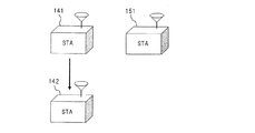
本実施形態の無線通信装置の構成を説明する。図9は、本実施形態の無線通信装置が被干渉無線機に相当する場合において、与干渉無線機となる他の無線通信装置を含む構成を示す概略図である。 The configuration of the wireless communication apparatus of this embodiment will be described. FIG. 9 is a schematic diagram showing a configuration including another wireless communication device that becomes an interfering wireless device when the wireless communication device of the present embodiment corresponds to an interfered wireless device.
本実施形態において、STA141は、STA151からの干渉を受け、CCA非対称状態を判定する被干渉無線機であるものとする。また、STA142は、STA141が送信したパケットを受信する無線機であるものとする。また、STA151は、ビーコンパケットのような、一定周期で固定長のパケットを送信し、STA141の送信パケットを検出することができずに、CCA非対称状態により干渉を与える与干渉無線機であるものとする。
In this embodiment, it is assumed that the
次に、CCA非対称状態の検出と改善を行う機能の構成について、図10を参照して説明する。図10は図9に示したSTA141の一構成例を示すブロック図である。
Next, the configuration of functions for detecting and improving the CCA asymmetric state will be described with reference to FIG. FIG. 10 is a block diagram showing a configuration example of the
図10に示すように、STA141は、無線通信処理部15と、送信特徴量測定部11と、通信特徴量記憶部12と、CCA非対称状態判定部13と、状態表示部18と、全体制御部16と、アプリケーション部17とを有する。STA141は、第1の実施形態で説明した送信特徴量測定部11、通信特徴量記憶部12、無線通信処理部15および全体制御部16を有しているが、本実施形態では、これらの構成について、第1の実施形態と異なる点を詳細に説明し、第1の実施形態と同様な動作の説明を省略する。
As shown in FIG. 10, the
送信特徴量測定部11は、自装置の無線通信処理部15の送信状態を測定し、送信特徴量を取得する。
The transmission feature amount measurement unit 11 measures the transmission state of the wireless
通信特徴量記憶部12は、送信特徴量測定部11にて取得された送信特徴量を記憶する。
The communication feature
CCA非対称状態判定部13は、通信特徴量記憶部12に保存された送信特徴量から、送信状態の測定を実施した装置がCCA非対称状態であるか否かを判定し、全体制御部16にその結果を出力する。
The CCA asymmetric
無線通信処理部15は、パケット送信を行う前に、CCAを行って送信チャネルが使用されているか否かを確認し、送信チャネルが未使用であれば、パケット送信を行う。また、無線通信処理部15は、送信特徴量測定部11が要求する送信状態情報を取得し、アプリケーション部17からの指示にしたがって送信パラメタを変更する。ここで、送信状態情報とは、無線通信処理部15がパケット送信を行う際の状態を示す情報を意味し、図5を参照して説明したパケット送信待機時間の情報を含む。
Before performing packet transmission, the wireless
状態表示部18は、全体制御部16からの指示に基づき、状態判定結果を表示する。状態表示部18は、例えば、液晶ディスプレイである。
The
全体制御部16は、CCA非対称状態の検出および改善を実行するために、送信特徴量測定部11、通信特徴量記憶部12、および状態表示部18を制御する。
The
アプリケーション部17は、パケットを生成し、無線通信処理部15を用いてパケットの送受信を行い、STA142と通信を行う。
The
なお、無線通信処理部15、送信特徴量測定部11、CCA非対称状態判定部13、アプリケーション部17および全体制御部16の各部は、第1の実施形態と同様に、専用の半導体集積回路であってもよく、CPUがプログラムを実行することで仮想的に構成されるものであってもよい。また、STA151がSTA141と同様な構成であってもよい。
Note that the wireless
次に、STA141が実行する、CCA非対称状態の検出と改善のための動作を説明する。図11は本実施形態の通信処理方法の手順を示すフローチャートである。図12は本実施形態における、CCA非対称状態の検出方法を説明するためのヒストグラムである。
Next, operations for detecting and improving the CCA asymmetric state performed by the
本実施形態では、STA151のビーコン送信によりSTA141のパケット送信待機時間が影響を受けることを利用してCCA非対称状態の検出を行う。
In the present embodiment, the detection of the CCA asymmetric state is performed using the fact that the packet transmission standby time of the
第1の処理として、後述する第3の処理で用いられる、理論上での送信特徴量の設定を行う(ステップ211)。具体的には、全体制御部16は、通信特徴量記憶部12に対して、送信特徴量として理論上でのパケット送信待機時間分布を記憶させる。図12(a)は理論上でのパケット送信待機時間分布の一例を示す。
As a first process, a theoretical transmission feature value used in a third process to be described later is set (step 211). Specifically, the
なお、第1の処理は、次に説明する第2の処理の直前に実施する必要はなく、工場出荷時に通信特徴量記憶部12に記憶させるなど、事前に実施してもよい。
The first process does not need to be performed immediately before the second process described below, and may be performed in advance, for example, stored in the communication feature
第2の処理として、実際の環境での送信特徴量を測定する(ステップ212)。以下に、第2の処理について詳しく説明する。 As a second process, a transmission feature amount in an actual environment is measured (step 212). Hereinafter, the second process will be described in detail.
先ず、全体制御部16が、送信特徴量測定部11に対し、無線通信処理部15がパケット送信を実施するたびに出力するパケット送信待機時間の取得、およびパケット送信待機時間分布の作成を開始するよう指示する。
First, the
全体制御部16から指示を受けた送信特徴量測定部11は、アプリケーション部17が無線通信処理部15からパケットを送信する度に無線通信処理部15が送信特徴量測定部11に出力するパケット送信待機時間の情報を受け取る。取得したパケット送信待機時間は、パケット送信待機時間分類単位幅Lpswcw[s]単位で区分され、その区分ごとに計数を行い、パケット送信待機時間分布が作成される。
Upon receiving an instruction from the
パケット送信待機時間の測定が開始されてから、状態測定期間Tmt[s]が経過すると、全体制御部16は、送信特徴量測定部11に対し、パケット送信待機時間の取得、およびパケット送信待機時間分布の作成を終了するよう指示する。指示を受けた送信特徴量測定部11は、パケット送信待機時間分布の取得を終了し、作成したパケット送信待機時間分布を通信特徴量記憶部12に保存する。図12(b)は測定したパケット送信待機時間分布の一例を示す。
When the state measurement period Tmt [s] elapses after the measurement of the packet transmission standby time is started, the
第3の処理として、CCA非対称状態判定部13において、測定されたパケット送信待機時間分布と、理論上でのパケット送信待機時間分布とを比較し、STA141とSTA151の間にCCA非対称状態が生じているかを判定する(ステップ213)。以下に、第3の処理について詳しく説明する。
As a third process, the CCA asymmetric
先ず、CCA非対称状態判定部13は、全体制御部16からCCA非対称状態判定実行の指示を受けると、通信特徴量記憶部12から、測定されたパケット送信待機時間分布と、理論上でのパケット送信待機時間分布を取得する。
First, upon receiving an instruction to execute CCA asymmetric state determination from the
CCA非対称状態判定部13は、図12に示すように、測定されたパケット送信待機時間分布(図12(b))から、理論上でのパケット送信待機時間分布(図12(a))を、パケット送信待機時間分類単位幅Lpswcw[s]単位で減算し、パケット送信待機時間分布差分を生成する(図12(c)参照)。
As shown in FIG. 12, the CCA asymmetric
図13は図12(c)に示したパケット送信待機時間分布差分を拡大して示したものである。比較として、CCA非対称状態でない場合における、図12(b)に相当する送信待機時間分布の一例を図14に示す。 FIG. 13 is an enlarged view of the packet transmission standby time distribution difference shown in FIG. As a comparison, FIG. 14 shows an example of a transmission standby time distribution corresponding to FIG. 12B when the CCA is not in an asymmetric state.
図13に示すように、パケット送信待機時間分布差分のプラス側に、CCA非対称状態か否かの判定対象となる分布が現われる。CCA非対称状態である場合、与干渉側であるSTA151が待ち合わせずにパケットを送信する。他方、被干渉側であるSTA141では、STA151の送信パケットが送信される都度送信を待ち合わせるため、STA151の送信パケット長分、送信待機時間が長くなるパケットが多く存在する。
As shown in FIG. 13, a distribution that is a determination target of whether or not the CCA is in an asymmetric state appears on the plus side of the packet transmission standby time distribution difference. In the CCA asymmetric state, the interfering
一方、CCA非対称状態ではない場合、STA151も、STA141が送信したパケットを検出して送信を待ち合わせる。そのため、図14に示すように、STA141では、CCA非対称状態に比べて送信待機時間が長いパケットの割合が低下する。
On the other hand, when not in the CCA asymmetric state, the
CCA非対称状態判定部13は、図13に示すように、生成したパケット送信待機時間分布差分において、平均被干渉パケット送信待機時間Tipsw[s]を中心とするピーク幅Ldw[s]分の要素(図13参照)の値の合計が存在比率閾値Pwp以上であれば、CCA非対称状態に依るパケット送信待機時間分布のピークが存在すると判定する。
As illustrated in FIG. 13, the CCA asymmetric
このときに用いる平均被干渉パケット送信待機時間、ピーク幅、および存在比率閾値のそれぞれの決定方法の一例を、以下に説明するが、これらの決定方法に限定されるものではない。 An example of each method for determining the average interfered packet transmission standby time, peak width, and existence ratio threshold value used at this time will be described below, but is not limited to these determination methods.
平均被干渉パケット送信待機時間Tipsw[s]は、以下の式5から求められる。 The average interfered packet transmission standby time Tipsw [s] is obtained from the following Equation 5.
式5において、Tpswave[s]はSTA141の通信規格に基づく理論上での平均パケット送信待機時間であり、Tbplen[s]はSTA151が送信するビーコンパケット信号の長さである。
In Equation 5, Tpswave [s] is a theoretical average packet transmission waiting time based on the communication standard of the
ピーク幅Ldw[s]は、以下の式6から求められる。 The peak width Ldw [s] is obtained from the following formula 6.
式6において、CWminはSTA141のCSMA/CAにおける送信1回目の最大バックオフスロット数であり、Tsl[s]はSTA141のバックオフスロット1つ分の時間長である。
In Equation 6, CWmin is the maximum number of backoff slots for the first transmission in the CSMA / CA of the
存在比率閾値Pwpは、以下の式7から求められる。 The existence ratio threshold value Pwp is obtained from the following Expression 7.
式7において、NspはSTA141が状態測定期間Tmt[s]中に送信したパケット数、NbpはSTA151が状態測定期間Tmt[s]中に送信したビーコンパケット数、Tbi[s]はSTA151のビーコンパケット送信間隔[s]である。
In Equation 7, Nsp is the number of packets transmitted by the
上記の式中で使用するTmt[s]、Tbi[s]、Tbplen[s]等のようなSTA151に係わる情報は、本実施形態においては、工場出荷時にSTA141の通信特徴量記憶部12に記憶させる等のように、事前にSTA141に対して記憶させておいてもよい。
In the present embodiment, information related to the
第4の処理として、CCA非対称状態の改善を行う(ステップ214)。以下に、第4の処理について詳しく説明する。 As a fourth process, the CCA asymmetric state is improved (step 214). Hereinafter, the fourth process will be described in detail.
CCA非対称状態による送信間隔分布のピークが検出された場合、CCA非対称状態判定部13は全体制御部16に対してCCA非対称状態であることを通知し、CCA非対称状態に依る送信間隔分布のピークが検出されない場合、CCA非対称状態判定部13は全体制御部16に対してCCA非対称状態ではないことを通知する。
When a transmission interval distribution peak due to the CCA asymmetric state is detected, the CCA asymmetric
全体制御部16は、CCA非対称状態判定部13から得た判定結果がCCA非対称状態を示すものであった場合、状態表示部18にCCA非対称状態であることを表示させる。状態表示部18がCCA非対称状態である旨を表示する場合、ユーザは、STA141の設置位置を変更し、CCA非対称状態とならないようにする。
When the determination result obtained from the CCA asymmetric
このとき、STA141とSTA151の距離を短くすれば、STA151がSTA141の送信を検出できるようになり、両者の間でCSMA/CAが良好に機能するようになる。また、STA141とSTA151の距離を離すことで、STA141がSTA151の送信を検出できなくなり、両者の間に影響関係はなくなる。その結果、CCA非対称状態が改善する。
At this time, if the distance between the
本実施形態では、上述のようにして、理論および実測のパケット送信特徴量の差分に基づいて、CCA非対称状態であるか否かを検出することが可能となり、次のような効果を奏する。 In the present embodiment, as described above, it is possible to detect whether or not the CCA is in an asymmetric state based on the difference between the theoretical and actually measured packet transmission feature amounts, and the following effects are obtained.
第1の効果は、CCA非対称状態を回避することで、与干渉側の一方的な送信による被干渉側の送信待ちをなくし、チャネルアクセス性の悪化を改善できることである。 The first effect is that by avoiding the CCA asymmetric state, waiting for transmission on the interfered side due to unilateral transmission on the interfering side can be eliminated, and deterioration of channel accessibility can be improved.
第2の効果は、CCA非対称状態を回避することで、与干渉側のパケットが被干渉側のパケットに衝突する可能性を低下させることである。 The second effect is to reduce the possibility that the interferer side packet collides with the interfered side packet by avoiding the CCA asymmetric state.
第3の効果は、上記第1の効果および第2の効果により、被干渉側、与干渉側の両者の通信効率が改善することである。 The third effect is that the communication efficiency on both the interfered side and the interfered side is improved by the first effect and the second effect.
なお、第1の実施形態で説明した無線通信装置に対して、状態表示部18を設け、第2の実施形態で説明した第4の処理を実行させてもよい。また、第2の実施形態で説明した無線通信装置に対して、送信パラメタ制御部14を設け、第1の実施形態で説明した第4の処理を実行させてもよい。
Note that the wireless communication device described in the first embodiment may be provided with the
さらに、本発明の通信処理方法の手順を記述したプログラムを無線通信装置に実行させてもよい。 Furthermore, the wireless communication apparatus may be caused to execute a program describing the procedure of the communication processing method of the present invention.
111、121、141、151 無線通信装置(STA)
131 ゲートウェイ装置(GW)
11 送信特徴量測定部
12 通信特徴量記憶部
13 CCA非対称状態判定部
14 送信パラメタ制御部
15 無線通信処理部
16 全体制御部
17 アプリケーション部
18 状態表示部
111, 121, 141, 151 Wireless communication equipment (STA)
131 Gateway device (GW)
DESCRIPTION OF SYMBOLS 11 Transmission feature-
Claims (8)
前記他の無線通信装置がパケット送信を停止している状態における前記無線通信処理部のパケット送信処理の特徴量である第1の送信特徴量、ならびに自装置および前記他の無線通信装置がパケット送信を行う状態における前記無線通信処理部のパケット送信処理の特徴量である第2の送信特徴量を取得する送信特徴量測定部と、
前記第1および前記第2の送信特徴量に基づいて、前記他の無線通信装置が自装置の信号検出圏内に位置しているが、該他の無線通信装置の信号検出圏外に自装置が位置する状態である信号検出圏非対称状態であるか否かを判定する非対称状態判定部と、
を有する無線通信装置。 A wireless communication processing unit that performs control to avoid collision of packets when transmitting a packet on the same channel as a packet transmitted from another wireless communication device;
A first transmission feature amount which is a feature amount of packet transmission processing of the wireless communication processing unit in a state where the other wireless communication device stops packet transmission, and the own device and the other wireless communication device transmit packets. A transmission feature amount measurement unit that acquires a second transmission feature amount that is a feature amount of packet transmission processing of the wireless communication processing unit in a state of performing
Based on the first and second transmission feature quantities, the other wireless communication apparatus is located within the signal detection area of the own apparatus, but the own apparatus is located outside the signal detection area of the other wireless communication apparatus. An asymmetric state determination unit that determines whether or not the signal detection sphere is in an asymmetric state,
A wireless communication device.
前記送信特徴量測定部は、
前記他の無線通信装置がパケット送信を停止している状態で前記無線通信処理部がパケット送信処理を所定の時間行ったときの、前記第1の送信特徴量を軸とした該第1の送信特徴量の頻度を示す第1の送信特徴量分布を取得し、自装置および前記他の無線通信装置がパケット送信を行う状態で前記無線通信処理部が前記パケット送信処理を所定の時間行ったときの、前記第2の送信特徴量を軸とした該第2の送信特徴量の頻度を示す第2の送信特徴量分布を取得し、
前記非対称状態判定部は、
前記第2の送信特徴量分布から前記第1の送信特徴量分布を差し引いた分布である送信特徴量分布差分を生成し、該送信特徴量分布差分のプラス側の分布において、最大値を中心とした所定の幅に含まれる頻度の合計が所定の閾値以上である場合、前記信号検出圏非対称状態であると判定し、該合計が前記所定の閾値よりも小さい場合、前記信号検出圏非対称状態ではないと判定する、無線通信装置。 The wireless communication device according to claim 1, wherein
The transmission feature amount measurement unit includes:
The first transmission with the first transmission feature amount as an axis when the wireless communication processing unit performs packet transmission processing for a predetermined time while the other wireless communication device stops packet transmission. When a first transmission feature amount distribution indicating the frequency of feature amounts is acquired, and the wireless communication processing unit performs the packet transmission processing for a predetermined time in a state where the own device and the other wireless communication device perform packet transmission Obtaining a second transmission feature quantity distribution indicating the frequency of the second transmission feature quantity with the second transmission feature quantity as an axis,
The asymmetric state determination unit
A transmission feature amount distribution difference, which is a distribution obtained by subtracting the first transmission feature amount distribution from the second transmission feature amount distribution, is generated, and a maximum value is centered on a plus-side distribution of the transmission feature amount distribution difference. When the sum of the frequencies included in the predetermined width is equal to or greater than a predetermined threshold, it is determined that the signal detection sphere is asymmetric, and when the sum is smaller than the predetermined threshold, the signal detection sphere asymmetric is A wireless communication device that determines that there is no.
前記非対称状態判定部が前記信号検出圏非対称状態であると判定すると、前記無線通信処理部または前記他の無線通信装置に対して、パケット送信処理に関するパラメタの変更を要求する送信パラメタ制御部をさらに有する、無線通信装置。 The wireless communication device according to claim 1 or 2,
When the asymmetric state determination unit determines that the signal detection sphere is in an asymmetric state, the wireless communication processing unit or the other wireless communication device further includes a transmission parameter control unit that requests a change of parameters relating to packet transmission processing A wireless communication device.
前記非対称状態判定部が前記信号検出圏非対称状態であると判定すると、該信号検出圏非対称状態である旨を表示する状態表示部をさらに有する、無線通信装置。 The wireless communication device according to claim 1 or 2,
The wireless communication apparatus further comprising a state display unit that displays that the signal detection area is asymmetric when the asymmetric state determination section determines that the signal detection area is asymmetric.
前記第1および前記第2の送信特徴量が、パケット送信間隔またはパケット送信待機時間である、無線通信装置。 The wireless communication device according to any one of claims 1 to 4,
The wireless communication apparatus, wherein the first and second transmission feature amounts are packet transmission intervals or packet transmission standby times.
前記無線通信装置と通信可能に接続され、該無線通信装置から受信する前記第1および前記第2の送信特徴量に基づいて、前記他の無線通信装置が該無線通信装置の信号検出圏内に位置しているが、該他の無線通信装置の信号検出圏外に該無線通信装置が位置する状態であるか否かを判定する非対称状態判定部を含むゲートウェイ装置と、
を有する通信システム。 When transmitting a packet on the same channel as a packet transmitted from another wireless communication device, a wireless communication processing unit that performs control to avoid packet collision, and the state in which the other wireless communication device has stopped packet transmission The first transmission feature amount that is the feature amount of the packet transmission processing of the wireless communication processing unit in FIG. 3 and the feature of the packet transmission processing of the wireless communication processing unit in a state where the own device and the other wireless communication device perform packet transmission A wireless communication device including a transmission feature amount measurement unit that acquires a second transmission feature amount that is a quantity;
Based on the first and second transmission feature quantities that are communicably connected to the wireless communication device and received from the wireless communication device, the other wireless communication device is located within a signal detection range of the wireless communication device. A gateway device including an asymmetric state determination unit that determines whether or not the wireless communication device is located outside the signal detection range of the other wireless communication device;
A communication system.
前記他の無線通信装置がパケット送信を停止している状態における、自装置のパケット送信処理の特徴量である第1の送信特徴量を取得し、
自装置および前記他の無線通信装置がパケット送信を行う状態における、自装置のパケット送信処理の特徴量である第2の送信特徴量を取得し、
前記第1および前記第2の送信特徴量に基づいて、前記他の無線通信装置が自装置の信号検出圏内に位置しているが、該他の無線通信装置の信号検出圏外に自装置が位置する状態であるか否かを判定する、通信処理方法。 A communication processing method by a wireless communication device that performs control to avoid collision of packets when transmitting a packet on the same channel as a packet transmitted from another wireless communication device,
Obtaining a first transmission feature amount that is a feature amount of packet transmission processing of the own device in a state where the other wireless communication device has stopped packet transmission;
Obtaining a second transmission feature amount that is a feature amount of packet transmission processing of the own device in a state where the own device and the other wireless communication device perform packet transmission;
Based on the first and second transmission feature quantities, the other wireless communication apparatus is located within the signal detection area of the own apparatus, but the own apparatus is located outside the signal detection area of the other wireless communication apparatus. A communication processing method for determining whether or not to be in a state to be performed.
前記他の無線通信装置がパケット送信を停止している状態における、自装置のパケット送信処理の特徴量である第1の送信特徴量を取得し、
自装置および前記他の無線通信装置がパケット送信を行う状態における、自装置のパケット送信処理の特徴量である第2の送信特徴量を取得し、
前記第1および前記第2の送信特徴量に基づいて、前記他の無線通信装置が自装置の信号検出圏内に位置しているが、該他の無線通信装置の信号検出圏外に自装置が位置する状態であるか否かを判定する処理を前記無線通信装置に実行させるためのプログラム。 When transmitting a packet on the same channel as a packet transmitted from another wireless communication device, a program for causing the wireless communication device to perform control to avoid packet collision,
Obtaining a first transmission feature amount that is a feature amount of packet transmission processing of the own device in a state where the other wireless communication device has stopped packet transmission;
Obtaining a second transmission feature amount that is a feature amount of packet transmission processing of the own device in a state where the own device and the other wireless communication device perform packet transmission;
Based on the first and second transmission feature quantities, the other wireless communication apparatus is located within the signal detection area of the own apparatus, but the own apparatus is located outside the signal detection area of the other wireless communication apparatus. A program for causing the wireless communication apparatus to execute a process of determining whether or not the wireless communication apparatus is in a state to be performed.
Priority Applications (1)
| Application Number | Priority Date | Filing Date | Title |
|---|---|---|---|
| JP2011182661A JP5725552B2 (en) | 2011-08-24 | 2011-08-24 | Wireless communication apparatus, communication system, communication processing method, and program |
Applications Claiming Priority (1)
| Application Number | Priority Date | Filing Date | Title |
|---|---|---|---|
| JP2011182661A JP5725552B2 (en) | 2011-08-24 | 2011-08-24 | Wireless communication apparatus, communication system, communication processing method, and program |
Publications (2)
| Publication Number | Publication Date |
|---|---|
| JP2013046229A JP2013046229A (en) | 2013-03-04 |
| JP5725552B2 true JP5725552B2 (en) | 2015-05-27 |
Family
ID=48009801
Family Applications (1)
| Application Number | Title | Priority Date | Filing Date |
|---|---|---|---|
| JP2011182661A Active JP5725552B2 (en) | 2011-08-24 | 2011-08-24 | Wireless communication apparatus, communication system, communication processing method, and program |
Country Status (1)
| Country | Link |
|---|---|
| JP (1) | JP5725552B2 (en) |
Families Citing this family (6)
| Publication number | Priority date | Publication date | Assignee | Title |
|---|---|---|---|---|
| CN109525998B (en) * | 2014-06-23 | 2022-05-17 | 瑞昱半导体股份有限公司 | Wireless communication device and method |
| JP2017537498A (en) | 2014-10-06 | 2017-12-14 | ヴィド スケール インコーポレイテッド | Adaptation of communication parameters to link conditions, traffic types, and / or priorities |
| JP6619802B2 (en) * | 2015-04-27 | 2019-12-11 | パナソニック インテレクチュアル プロパティ コーポレーション オブ アメリカPanasonic Intellectual Property Corporation of America | Transmission method, transmission control method, and communication apparatus |
| JP6743497B2 (en) * | 2016-06-13 | 2020-08-19 | ソニー株式会社 | Communication device, communication method, program, and communication system |
| JP7039181B2 (en) * | 2016-11-02 | 2022-03-22 | パナソニック インテレクチュアル プロパティ コーポレーション オブ アメリカ | non-PCP / AP communication device and communication method |
| CN106714208A (en) * | 2016-12-12 | 2017-05-24 | 南京理工大学 | Fixed packet transmission delivery ratio half-blind self-adaptive optimization method for network |
Family Cites Families (2)
| Publication number | Priority date | Publication date | Assignee | Title |
|---|---|---|---|---|
| US7623494B2 (en) * | 2006-05-18 | 2009-11-24 | Intel Corporation | Adjustment of a clear channel assessment (CCA) threshold |
| US20070286122A1 (en) * | 2006-06-12 | 2007-12-13 | Motorola, Inc. | Clear channel assessment threshold adaptation in a wireless network |
-
2011
- 2011-08-24 JP JP2011182661A patent/JP5725552B2/en active Active
Also Published As
| Publication number | Publication date |
|---|---|
| JP2013046229A (en) | 2013-03-04 |
Similar Documents
| Publication | Publication Date | Title |
|---|---|---|
| US11438925B2 (en) | Techniques of improving EDCA mechanism in spatial reuse | |
| JP5148756B2 (en) | Radio station | |
| US10045239B2 (en) | Method and system for detecting idle channel in wireless communication system | |
| JP5531338B2 (en) | Interference detection device, interference avoidance device, wireless communication device, wireless network system, interference detection method, interference avoidance method, and program | |
| JP5725552B2 (en) | Wireless communication apparatus, communication system, communication processing method, and program | |
| US20070286122A1 (en) | Clear channel assessment threshold adaptation in a wireless network | |
| US9031009B2 (en) | Transmitting/receiving device, wireless terminal device and wireless communication method for suppression of intra-system interference | |
| US20060046739A1 (en) | Method and apparatus for improving performance in wireless networks by tuning receiver sensitivity thresholds | |
| CN108702640B (en) | Wireless environment determination method and wireless communication system | |
| JP7224542B2 (en) | Hybrid Carrier Sense Multiple Access System with Collision Avoidance for IEEE 802.15.4 to Achieve Better Coexistence with IEEE 802.11 | |
| US11297650B2 (en) | Systems and methods for signal detection using PHY layer processing | |
| WO2008075177A2 (en) | Techniques for rts/cts usage for wireless networks | |
| CN107615869B (en) | Wireless device, access point and method using different Clear Channel Assessment (CCA) thresholds | |
| US10910881B2 (en) | Electronic apparatus | |
| US20180132251A1 (en) | User Equipment Sending Signal Directly to User Equipment | |
| US11419149B2 (en) | Systems and methods for latency reduction in backhaul | |
| JP2010124056A (en) | Wireless station, communication control method and communication program | |
| KR101674968B1 (en) | Wireless Communication System for collision avoidance in the fire area and Method for collision avoidance using the same | |
| US9860921B2 (en) | Method and apparatus for transmitting and receiving data based on aggressive spatial reuse | |
| US11166311B2 (en) | Systems and methods utilizing channel spatial properties with CSMA | |
| CN108702787B (en) | Method, apparatus, and non-transitory computer readable medium for accessing a wireless communication medium | |
| Choi et al. | Delay analysis of carrier sense multiple access with collision resolution | |
| KR102216010B1 (en) | Method and apparatus for transmitting and receiving data based on aggressive spatial reuse |
Legal Events
| Date | Code | Title | Description |
|---|---|---|---|
| RD04 | Notification of resignation of power of attorney |
Free format text: JAPANESE INTERMEDIATE CODE: A7424 Effective date: 20140527 |
|
| A621 | Written request for application examination |
Free format text: JAPANESE INTERMEDIATE CODE: A621 Effective date: 20140704 |
|
| A977 | Report on retrieval |
Free format text: JAPANESE INTERMEDIATE CODE: A971007 Effective date: 20150212 |
|
| TRDD | Decision of grant or rejection written | ||
| A01 | Written decision to grant a patent or to grant a registration (utility model) |
Free format text: JAPANESE INTERMEDIATE CODE: A01 Effective date: 20150303 |
|
| A61 | First payment of annual fees (during grant procedure) |
Free format text: JAPANESE INTERMEDIATE CODE: A61 Effective date: 20150326 |
|
| R150 | Certificate of patent or registration of utility model |
Ref document number: 5725552 Country of ref document: JP Free format text: JAPANESE INTERMEDIATE CODE: R150 |
|
| R250 | Receipt of annual fees |
Free format text: JAPANESE INTERMEDIATE CODE: R250 |
|
| R250 | Receipt of annual fees |
Free format text: JAPANESE INTERMEDIATE CODE: R250 |
|
| R250 | Receipt of annual fees |
Free format text: JAPANESE INTERMEDIATE CODE: R250 |
|
| R250 | Receipt of annual fees |
Free format text: JAPANESE INTERMEDIATE CODE: R250 |
|
| R250 | Receipt of annual fees |
Free format text: JAPANESE INTERMEDIATE CODE: R250 |
|
| R250 | Receipt of annual fees |
Free format text: JAPANESE INTERMEDIATE CODE: R250 |
|
| R250 | Receipt of annual fees |
Free format text: JAPANESE INTERMEDIATE CODE: R250 |