JP5723785B2 - System, method and respiratory device for supporting a subject's airway - Google Patents
System, method and respiratory device for supporting a subject's airway Download PDFInfo
- Publication number
- JP5723785B2 JP5723785B2 JP2011542949A JP2011542949A JP5723785B2 JP 5723785 B2 JP5723785 B2 JP 5723785B2 JP 2011542949 A JP2011542949 A JP 2011542949A JP 2011542949 A JP2011542949 A JP 2011542949A JP 5723785 B2 JP5723785 B2 JP 5723785B2
- Authority
- JP
- Japan
- Prior art keywords
- subject
- airway
- resistance
- gas
- flow
- Prior art date
- Legal status (The legal status is an assumption and is not a legal conclusion. Google has not performed a legal analysis and makes no representation as to the accuracy of the status listed.)
- Active
Links
- 230000000241 respiratory effect Effects 0.000 title claims description 83
- 238000000034 method Methods 0.000 title description 40
- 230000029058 respiratory gaseous exchange Effects 0.000 claims description 62
- 230000001965 increasing effect Effects 0.000 claims description 20
- 239000012528 membrane Substances 0.000 claims description 9
- 230000002829 reductive effect Effects 0.000 claims description 9
- 206010041235 Snoring Diseases 0.000 claims description 7
- 239000007789 gas Substances 0.000 description 263
- 239000003570 air Substances 0.000 description 111
- 230000001186 cumulative effect Effects 0.000 description 37
- 230000006870 function Effects 0.000 description 17
- 230000000670 limiting effect Effects 0.000 description 17
- 238000012544 monitoring process Methods 0.000 description 16
- 238000011282 treatment Methods 0.000 description 14
- 230000004888 barrier function Effects 0.000 description 13
- 230000007246 mechanism Effects 0.000 description 13
- 238000012545 processing Methods 0.000 description 12
- 230000001225 therapeutic effect Effects 0.000 description 12
- 230000007958 sleep Effects 0.000 description 11
- 238000004891 communication Methods 0.000 description 6
- 230000007423 decrease Effects 0.000 description 6
- 230000008569 process Effects 0.000 description 6
- 238000002560 therapeutic procedure Methods 0.000 description 6
- 230000008859 change Effects 0.000 description 5
- 239000000853 adhesive Substances 0.000 description 4
- 230000001070 adhesive effect Effects 0.000 description 4
- 230000008901 benefit Effects 0.000 description 4
- 238000010586 diagram Methods 0.000 description 4
- QVGXLLKOCUKJST-UHFFFAOYSA-N atomic oxygen Chemical compound [O] QVGXLLKOCUKJST-UHFFFAOYSA-N 0.000 description 3
- 238000004140 cleaning Methods 0.000 description 3
- 239000000203 mixture Substances 0.000 description 3
- 210000003928 nasal cavity Anatomy 0.000 description 3
- 239000001301 oxygen Substances 0.000 description 3
- 229910052760 oxygen Inorganic materials 0.000 description 3
- 229920000642 polymer Polymers 0.000 description 3
- 230000009467 reduction Effects 0.000 description 3
- 230000004044 response Effects 0.000 description 3
- 238000000926 separation method Methods 0.000 description 3
- 230000007704 transition Effects 0.000 description 3
- MWUXSHHQAYIFBG-UHFFFAOYSA-N Nitric oxide Chemical compound O=[N] MWUXSHHQAYIFBG-UHFFFAOYSA-N 0.000 description 2
- 230000003247 decreasing effect Effects 0.000 description 2
- 239000012530 fluid Substances 0.000 description 2
- 210000003128 head Anatomy 0.000 description 2
- 230000010365 information processing Effects 0.000 description 2
- 238000005259 measurement Methods 0.000 description 2
- 210000001331 nose Anatomy 0.000 description 2
- 238000007789 sealing Methods 0.000 description 2
- 230000035945 sensitivity Effects 0.000 description 2
- 238000009423 ventilation Methods 0.000 description 2
- 206010001029 Acute pulmonary oedema Diseases 0.000 description 1
- 208000000884 Airway Obstruction Diseases 0.000 description 1
- 206010038669 Respiratory arrest Diseases 0.000 description 1
- 208000013738 Sleep Initiation and Maintenance disease Diseases 0.000 description 1
- 238000009825 accumulation Methods 0.000 description 1
- 230000004913 activation Effects 0.000 description 1
- 230000002411 adverse Effects 0.000 description 1
- 239000012080 ambient air Substances 0.000 description 1
- 238000013459 approach Methods 0.000 description 1
- 230000003190 augmentative effect Effects 0.000 description 1
- 230000015572 biosynthetic process Effects 0.000 description 1
- 239000003795 chemical substances by application Substances 0.000 description 1
- 238000010276 construction Methods 0.000 description 1
- 238000013461 design Methods 0.000 description 1
- 239000003814 drug Substances 0.000 description 1
- 229940079593 drug Drugs 0.000 description 1
- 238000001647 drug administration Methods 0.000 description 1
- 230000000694 effects Effects 0.000 description 1
- 238000005516 engineering process Methods 0.000 description 1
- 230000002708 enhancing effect Effects 0.000 description 1
- 239000000017 hydrogel Substances 0.000 description 1
- 238000003780 insertion Methods 0.000 description 1
- 230000037431 insertion Effects 0.000 description 1
- 206010022437 insomnia Diseases 0.000 description 1
- 230000002452 interceptive effect Effects 0.000 description 1
- 210000004072 lung Anatomy 0.000 description 1
- 238000007726 management method Methods 0.000 description 1
- 238000004519 manufacturing process Methods 0.000 description 1
- 239000002184 metal Substances 0.000 description 1
- 239000003595 mist Substances 0.000 description 1
- 238000012986 modification Methods 0.000 description 1
- 230000004048 modification Effects 0.000 description 1
- 239000002086 nanomaterial Substances 0.000 description 1
- 230000001537 neural effect Effects 0.000 description 1
- 230000000414 obstructive effect Effects 0.000 description 1
- 208000001797 obstructive sleep apnea Diseases 0.000 description 1
- 238000001126 phototherapy Methods 0.000 description 1
- 230000035479 physiological effects, processes and functions Effects 0.000 description 1
- 238000003825 pressing Methods 0.000 description 1
- 230000001373 regressive effect Effects 0.000 description 1
- 239000012858 resilient material Substances 0.000 description 1
- 230000004202 respiratory function Effects 0.000 description 1
- 230000036387 respiratory rate Effects 0.000 description 1
- 201000002859 sleep apnea Diseases 0.000 description 1
- 208000019116 sleep disease Diseases 0.000 description 1
- 208000020685 sleep-wake disease Diseases 0.000 description 1
- 230000000087 stabilizing effect Effects 0.000 description 1
- 230000003068 static effect Effects 0.000 description 1
- 230000000153 supplemental effect Effects 0.000 description 1
- 208000024891 symptom Diseases 0.000 description 1
- 208000011580 syndromic disease Diseases 0.000 description 1
- 238000012360 testing method Methods 0.000 description 1
- 238000013022 venting Methods 0.000 description 1
- XLYOFNOQVPJJNP-UHFFFAOYSA-N water Substances O XLYOFNOQVPJJNP-UHFFFAOYSA-N 0.000 description 1
- 230000003442 weekly effect Effects 0.000 description 1
Images


Classifications
-
- A—HUMAN NECESSITIES
- A61—MEDICAL OR VETERINARY SCIENCE; HYGIENE
- A61M—DEVICES FOR INTRODUCING MEDIA INTO, OR ONTO, THE BODY; DEVICES FOR TRANSDUCING BODY MEDIA OR FOR TAKING MEDIA FROM THE BODY; DEVICES FOR PRODUCING OR ENDING SLEEP OR STUPOR
- A61M16/00—Devices for influencing the respiratory system of patients by gas treatment, e.g. mouth-to-mouth respiration; Tracheal tubes
- A61M16/06—Respiratory or anaesthetic masks
- A61M16/0666—Nasal cannulas or tubing
-
- A—HUMAN NECESSITIES
- A61—MEDICAL OR VETERINARY SCIENCE; HYGIENE
- A61M—DEVICES FOR INTRODUCING MEDIA INTO, OR ONTO, THE BODY; DEVICES FOR TRANSDUCING BODY MEDIA OR FOR TAKING MEDIA FROM THE BODY; DEVICES FOR PRODUCING OR ENDING SLEEP OR STUPOR
- A61M16/00—Devices for influencing the respiratory system of patients by gas treatment, e.g. mouth-to-mouth respiration; Tracheal tubes
- A61M16/20—Valves specially adapted to medical respiratory devices
- A61M16/201—Controlled valves
- A61M16/202—Controlled valves electrically actuated
- A61M16/203—Proportional
- A61M16/205—Proportional used for exhalation control
-
- A—HUMAN NECESSITIES
- A61—MEDICAL OR VETERINARY SCIENCE; HYGIENE
- A61M—DEVICES FOR INTRODUCING MEDIA INTO, OR ONTO, THE BODY; DEVICES FOR TRANSDUCING BODY MEDIA OR FOR TAKING MEDIA FROM THE BODY; DEVICES FOR PRODUCING OR ENDING SLEEP OR STUPOR
- A61M16/00—Devices for influencing the respiratory system of patients by gas treatment, e.g. mouth-to-mouth respiration; Tracheal tubes
- A61M16/021—Devices for influencing the respiratory system of patients by gas treatment, e.g. mouth-to-mouth respiration; Tracheal tubes operated by electrical means
- A61M16/022—Control means therefor
- A61M16/024—Control means therefor including calculation means, e.g. using a processor
-
- A—HUMAN NECESSITIES
- A61—MEDICAL OR VETERINARY SCIENCE; HYGIENE
- A61M—DEVICES FOR INTRODUCING MEDIA INTO, OR ONTO, THE BODY; DEVICES FOR TRANSDUCING BODY MEDIA OR FOR TAKING MEDIA FROM THE BODY; DEVICES FOR PRODUCING OR ENDING SLEEP OR STUPOR
- A61M16/00—Devices for influencing the respiratory system of patients by gas treatment, e.g. mouth-to-mouth respiration; Tracheal tubes
- A61M16/0003—Accessories therefor, e.g. sensors, vibrators, negative pressure
- A61M2016/0027—Accessories therefor, e.g. sensors, vibrators, negative pressure pressure meter
-
- A—HUMAN NECESSITIES
- A61—MEDICAL OR VETERINARY SCIENCE; HYGIENE
- A61M—DEVICES FOR INTRODUCING MEDIA INTO, OR ONTO, THE BODY; DEVICES FOR TRANSDUCING BODY MEDIA OR FOR TAKING MEDIA FROM THE BODY; DEVICES FOR PRODUCING OR ENDING SLEEP OR STUPOR
- A61M2205/00—General characteristics of the apparatus
- A61M2205/50—General characteristics of the apparatus with microprocessors or computers
-
- A—HUMAN NECESSITIES
- A61—MEDICAL OR VETERINARY SCIENCE; HYGIENE
- A61M—DEVICES FOR INTRODUCING MEDIA INTO, OR ONTO, THE BODY; DEVICES FOR TRANSDUCING BODY MEDIA OR FOR TAKING MEDIA FROM THE BODY; DEVICES FOR PRODUCING OR ENDING SLEEP OR STUPOR
- A61M2206/00—Characteristics of a physical parameter; associated device therefor
- A61M2206/10—Flow characteristics
Description
この特許出願は、2008年12月30日に出願された仮出願番号第61/141,250号について、米国35USC119(e)の下、優先権の利益を享受し、その内容が参照によりここに組み込まれる。 This patent application enjoys the benefit of priority under Provisional Application No. 61 / 141,250 filed December 30, 2008 under US 35 USC 119 (e), the contents of which are hereby incorporated by reference. Incorporated.
この出願は、2008年12月30日に出願の米国特許出願第61/141,270号、2008年12月30日に出願の米国特許出願第61/141,251号及び2008年12月30日に出願の米国特許出願第61/141,252号に関係し、これらは完全にこの出願に組み込まれる。 No. 61 / 141,270 filed on Dec. 30, 2008, U.S. Patent Application No. 61 / 141,251 filed Dec. 30, 2008, and Dec. 30, 2008. No. 61 / 141,252, which is incorporated by reference in its entirety.
本発明は、被験者が呼吸するとき被験者の気道をサポートすることに関する。 The present invention relates to supporting a subject's airways as the subject breathes.
睡眠障害の呼吸で苦しむ患者は、とりわけ連続陽性気道圧、比例陽性気道圧及び比例支援ベンチレーションのようなベンチレーションの所定のモードに従って呼吸ガスの圧力がかかった流れを供給する陽性気道圧(PAP)装置で、通常治療される。圧力がかかったガスは、睡眠障害の呼吸と関連する呼吸の停止の発現が低減されるか又は回避されるように、患者が眠るとき患者の気道をサポートする。PAP装置は、患者に不快であろう。これは、治療についての患者の遵守を低減させ、幾人かの患者が概して治療を中止するまでに至らせる。 Patients suffering from sleep disordered breathing have positive airway pressure (PAP) that delivers a flow of breathing gas pressure according to a predetermined mode of ventilation, such as continuous positive airway pressure, proportional positive airway pressure and proportional support ventilation, among others. ) The device is usually treated. The pressurized gas supports the patient's airways when the patient sleeps so that the occurrence of respiratory arrest associated with sleep disordered breathing is reduced or avoided. The PAP device will be uncomfortable for the patient. This reduces patient compliance with treatment, leading to some patients generally discontinuing treatment.
睡眠障害の呼吸のための他の治療は、患者からの呼気の流れに抵抗する気道抵抗を使用し、これによって、呼気の間、気道をサポートしていた。しかしながら、従来の気道抵抗は、治療の間、気道内に配置されるので、幾らかの患者にとって不快であり、幾らか非衛生的である。例えば、患者の鼻孔内での従来の気道抵抗の処置は、鼻孔の内部断面積も減らし、このことは抵抗により供給される治療に悪影響を与えるかもしれない。更に、気道抵抗は、患者の気道から除去されるか、又は適所に抵抗を保持するために、(例えば、鼻孔周辺に)接着剤を付ける。場合によっては、従来の気道抵抗は、不快であると幾人かの患者により思われ、幾人かの患者に適切なサポートを提供しない。例えば、吸入の間、従来の気道抵抗は、完全にサポートされないように気道から離すか、又は吸入されたガスの流れに対する幾らかの抵抗のため圧力を低減さえする。 Other treatments for sleep disorder breathing used airway resistance that resisted the flow of exhaled air from the patient, thereby supporting the airway during exhalation. However, conventional airway resistance is uncomfortable and somewhat unhygienic for some patients because it is placed in the airway during treatment. For example, conventional treatment of airway resistance within a patient's nostril also reduces the internal cross-sectional area of the nostril, which may adversely affect the therapy provided by the resistance. In addition, airway resistance is removed from the patient's airway or adhesive is applied (eg, around the nostrils) to hold the resistance in place. In some cases, conventional airway resistance appears to be uncomfortable by some patients and does not provide adequate support for some patients. For example, during inhalation, conventional airway resistance moves away from the airway so that it is not fully supported, or even reduces pressure due to some resistance to inhaled gas flow.
本発明の一つの態様は、被験者が呼吸するとき、被験者の気道をサポートするように構成される呼吸機器に関係する。一つの実施例では、呼吸機器は、ボディと一つ以上の吸入バルブのセットとを有する。ボディは、被験者の気道の一つ以上の外口を囲むように構成される。ボディは、被験者の気道の一つ以上の外口と外気との間に複数の流路を形成し、当該複数の流路が複数の流路の全てではないが一つ以上の流路で作られた流路の第1のサブセットを有する。一つ以上の吸入バルブのセットが、流路の第1のサブセットに配置され、流路の第1のサブセット内で被験者の気道の一つ以上の外口へ、ガスが外気から比較的自由に流れることを可能にする。一つ以上の吸入バルブは、流路の第1のサブセット内で被験者の気道の一つ以上の外口から外気へのガスの流れに著しく抵抗するか又は封止する。外気から被験者の気道の一つ以上の外口へ通るガスのためボディにより形成される複数の流路内のガスの流れに対する累積的な抵抗は、被験者がボディを通って自由に吸入できるほど充分に低く、被験者の気道の一つ以上の外口から外気へ通るガスのためボディにより形成される複数の流路内のガスの流れに対する累積的な抵抗は、被験者によるボディを通る呼気が、呼気の間気道をサポートする圧力を被験者の気道内に作るのに充分高い。 One aspect of the invention relates to a respiratory device configured to support a subject's airways when the subject breathes. In one embodiment, the respiratory device has a body and a set of one or more inhalation valves. The body is configured to enclose one or more outer openings of the subject's airway. The body forms a plurality of channels between one or more outer openings of the subject's airway and the outside air, and the plurality of channels are formed by one or more channels, but not all of the plurality of channels. A first subset of the flow paths formed. A set of one or more inhalation valves is disposed in the first subset of the flow paths, and the gas is relatively free from the outside air to one or more external openings in the subject's airways within the first subset of the flow paths. Allows to flow. The one or more inhalation valves significantly resist or seal the flow of gas from the one or more outer ports of the subject's airway into the outside air within the first subset of the flow paths. The cumulative resistance to gas flow in the multiple channels formed by the body for gas passing from outside air to one or more outlets in the subject's airway is sufficient for the subject to freely inhale through the body The cumulative resistance to the flow of gas in the plurality of channels formed by the body due to gas passing from one or more outside openings of the subject's airway to the outside air is such that exhalation through the body by the subject High enough to create pressure in the subject's airway to support the airway during
本発明の別の態様は、被験者が呼吸するとき被験者の気道をサポートする方法に関する。一つの実施例では、当該方法は、気道の一つ以上の外口と外気との間に複数の流路を形成するボディで被験者の気道の一つ以上の外口を囲むステップであって、複数の流路が複数の流路の全てではないが一つ以上の流路で作られる流路の第1のサブセットを有する当該ステップと、吸入の間、外気から気道の一つ以上の外口へボディを通るガスの流れのため複数の流路内のガスの流れに対する第1の累積的な抵抗を供給するステップであって、第1の累積的な抵抗は、ガスが実質的に妨げられずに気道の一つ以上の外口へ外気から吸入される程充分に低い当該ステップと、呼気の間、ボディにより形成される複数の流路の他の流路を通るガスの流れを実質的に制限することなく、流路の第1のサブセットを通るガスの流れを制限することにより、気道の一つ以上の外口から外気へボディを通るガスの流れに対する第2の累積的な抵抗を供給するステップであって、第2の累積的な抵抗は、高い圧力が被験者の気道をサポートするように、ボディを通って呼気されるガスが被験者の気道内の圧力を上昇させるのに充分高い当該ステップとを有する。 Another aspect of the invention relates to a method of supporting a subject's airways when the subject breathes. In one embodiment, the method includes the step of enclosing one or more outer openings of the subject's airway with a body forming a plurality of channels between the one or more outer openings of the airway and the outside air, One or more outlets of the airway from outside air during inhalation, wherein the step has a first subset of channels made up of one or more channels, but not all of the plurality of channels Providing a first cumulative resistance to gas flow in the plurality of flow paths for gas flow through the body, wherein the first cumulative resistance is substantially impeded by the gas. The step is low enough to be drawn from the outside air into one or more outside openings of the airway, and the flow of gas through the other channels of the plurality of channels formed by the body during expiration Without restricting the flow of gas through the first subset of the flow paths. Supplying a second cumulative resistance to the flow of gas through the body from one or more outside openings of the airway to the outside air, wherein the second cumulative resistance is such that a high pressure is applied to the subject's airway. In order to support, the gas exhaled through the body has such a step high enough to increase the pressure in the subject's airway.
本発明の別の態様は、被験者が呼吸するとき被験者の気道をサポートするように構成されるシステムに関係する。一つの実施例では、当該システムは、気道の一つ以上の外口と外気との間に複数の流路を形成するボディで被験者の気道の一つ以上の外口を囲むための手段であって、複数の流路が複数の流路の全てではないが一つ以上の流路で作られる流路の第1のサブセットを有する当該手段と、吸入の間、外気から気道の一つ以上の外口へボディを通るガスの流れのため複数の流路内のガスの流れに対する第1の累積的な抵抗を供給するための手段であって、第1の累積的な抵抗は、ガスが実質的に妨げられずに気道の一つ以上の外口へ外気から吸入されるのに充分に低い当該手段と、呼気の間、ボディにより形成される複数の流路の他の流路を通るガスの流れを実質的に制限することなく、流路の第1のサブセットを通るガスの流れを制限することにより、気道の一つ以上の外口から外気へボディを通るガスの流れに対する第2の累積的な抵抗を供給するための手段であって、第2の累積的な抵抗は、高い圧力が被験者の気道をサポートするように、ボディを通って呼気されるガスが被験者の気道内で圧力を上昇させるのに充分高い当該手段とを有する。 Another aspect of the invention relates to a system configured to support a subject's airway as the subject breathes. In one embodiment, the system is a means for surrounding one or more outer openings of a subject's airway with a body that forms a plurality of channels between one or more outer openings of the airway and the outside air. The means having a first subset of channels, the plurality of channels being made up of one or more channels, but not all of the plurality of channels, and one or more of the airways from outside air during inhalation Means for providing a first cumulative resistance to a gas flow in the plurality of flow paths for the flow of gas through the body to the outer port, wherein the first cumulative resistance Gas that passes through the other channels of the plurality of channels formed by the body during exhalation, and the means low enough to be inhaled from the outside air into one or more outer ports of the airway without being obstructed Limiting the flow of gas through the first subset of the flow paths without substantially limiting the flow of Means for supplying a second cumulative resistance to the flow of gas through the body from one or more outside openings of the airway to the outside air, wherein the second cumulative resistance is a high pressure applied to the subject. So that the gas exhaled through the body is high enough to increase the pressure in the subject's airway so as to support the airway.
本発明の他の観点は、被験者が呼吸するとき被験者の気道をサポートするように構成される呼吸機器に関係する。一つの実施例では、呼吸機器は、ボディ、一つ以上のバルブ及びプロセッサを有する。ボディは、被験者の気道の一つ以上の外口を囲むように構成される。一つ以上のバルブがボディ内に配置され、ボディの内部からボディの外部へのガスの流れに対する制御可能な抵抗を供給するように構成される。プロセッサは、ボディの内部からボディの外部へのガスの流れに対する一つ以上のバルブの抵抗を制御するように構成される。 Another aspect of the present invention relates to a respiratory device that is configured to support a subject's airways when the subject breathes. In one embodiment, the respiratory device has a body, one or more valves, and a processor. The body is configured to enclose one or more outer openings of the subject's airway. One or more valves are disposed within the body and configured to provide a controllable resistance to gas flow from the interior of the body to the exterior of the body. The processor is configured to control the resistance of one or more valves to the flow of gas from the interior of the body to the exterior of the body.
本発明の他の観点は、被験者が呼吸するとき、被験者の気道をサポートする方法に関係する。一つの実施例では、当該方法は、被験者の気道の一つ以上の外口を囲むステップと、一つ以上の流路のガスの流れに対する抵抗を制御するステップとを有し、前記一つ以上の流路を通るガスが、被験者の気道の囲まれた一つ以上の外口から外気へ通気される。 Another aspect of the invention relates to a method of supporting a subject's airways as the subject breathes. In one embodiment, the method comprises the steps of enclosing one or more outer openings of the subject's airway and controlling resistance to gas flow in one or more flow paths, the one or more The gas passing through the flow path is vented to the outside air from one or more outside ports surrounded by the subject's airway.
本発明の他の観点は、被験者が呼吸するとき、被験者の気道をサポートするように構成される呼吸機器に関係する。一つの実施例では、当該呼吸機器は、被験者の気道の一つ以上の外口を囲むための手段と、一つ以上の流路のガスの流れに対する抵抗を制御するための手段とを有し、前記一つ以上の流路を通るガスが、被験者の気道の囲まれた一つ以上外口から外気へ通気される。 Another aspect of the present invention relates to a respiratory device configured to support a subject's airways when the subject breathes. In one embodiment, the respiratory device comprises means for enclosing one or more external openings in the subject's airway and means for controlling resistance to gas flow in one or more flow paths. The gas passing through the one or more flow paths is vented from one or more outer ports surrounded by the subject's airway to the outside air.
本発明の他の観点は、被験者が呼吸するとき被験者の気道をサポートするように構成されるシステムに関係する。一つの実施例では、当該システムは、呼吸機器、圧力生成器及び回路を有する。呼吸機器は、外気と被験者の気道の一つ以上の外口との間のガスの流れを制御するように構成される。呼吸機器は、外気から呼吸機器を通って被験者の気道を通るガスのためのガスの流れに対する第1の抵抗と、被験者の気道から呼吸機器を通って外気へ流れるガスのためのガスの流れに対する第2の抵抗とを持つ。第1の抵抗は、吸入の間、ガスが、実質的に妨げられずに外気から呼吸機器を通って被験者の気道を通るように、第2の抵抗より著しく低く、呼気の間、被験者の気道から外気へ流れるガスに対する呼吸機器の第2の抵抗は、上昇した圧力が被験者の気道をサポートするように、被験者の気道内で圧力を上昇させる。圧力生成器は、呼吸可能なガスの圧力がかかった流れを生成するように構成される。回路は、呼吸機器を介して圧力生成器から被験者の気道へ呼吸可能なガスの圧力がかかった流れを送る圧力生成器と呼吸機器との間にガス流路を形成する。 Another aspect of the invention relates to a system configured to support a subject's airway as the subject breathes. In one embodiment, the system includes a respiratory device, a pressure generator, and circuitry. The breathing device is configured to control the flow of gas between the outside air and one or more outlets of the subject's airway. The respiratory device is responsive to a first resistance to gas flow for gas from the outside air through the respiratory device and through the subject's airway to a gas flow for gas flowing from the subject's airway through the respiratory device to the outside air. With a second resistor. The first resistance is significantly lower than the second resistance so that during inhalation gas passes from the outside air through the breathing device through the subject's airway substantially unimpeded, and during the exhalation, the subject's airway The second resistance of the breathing device to gas flowing from to the outside air increases the pressure in the subject's airway so that the increased pressure supports the subject's airway. The pressure generator is configured to generate a pressured flow of breathable gas. The circuit forms a gas flow path between the pressure generator and the breathing device that sends a pressurized flow of breathable gas from the pressure generator to the subject's airway through the breathing device.
本発明の他の観点は、被験者が呼吸するとき、被験者の気道をサポートする方法に関係する。一つの実施例では、当該方法は、被験者の吸入の間、外気から被験者の気道の一つ以上の外口へ通るガスのためのガスの流れに対する第1の抵抗を供給するステップと、被験者の呼気の間、被験者の気道の一つ以上の外口から外気へ流れるガスのためのガスの流れに対する第2の抵抗を供給するステップであって、第1の抵抗は、吸入の間、ガスが、実質的に妨げられずに外気から呼吸機器を通って被験者の気道を通るように、第2の抵抗より著しく低く、呼気の間、被験者の気道から外気へ流れるガスに対する呼吸機器の第2の抵抗は、上昇した圧力が被験者の気道をサポートするように、被験者の気道内で圧力を上昇させる当該ステップと、呼吸可能なガスの圧力がかかった流れを生成するステップと、被験者が呼吸するとき、呼吸可能なガスの圧力がかかった流れを被験者の気道の一つ以上の外口に送るステップとを有する。 Another aspect of the invention relates to a method of supporting a subject's airways as the subject breathes. In one embodiment, the method includes providing a first resistance to gas flow for gas passing from outside air to one or more outlets of the subject's airway during inhalation of the subject; Providing a second resistance to the gas flow for the gas flowing from one or more exterior ports of the subject's airway into the outside air during exhalation, wherein the first resistance Significantly lower than the second resistance so that it passes through the breathing device from the outside air through the breathing device substantially unimpeded, and the second of the breathing device against gas flowing from the subject's airway to the outside air during expiration. Resistance includes the steps of increasing the pressure in the subject's airway so that the increased pressure supports the subject's airway, generating a pressured flow of breathable gas, and when the subject breathes Breathable And a step of sending a flow pressure of the gas is applied to one or more external ports of an airway of a subject.
本発明の他の観点は、被験者が呼吸するとき被験者の気道をサポートするように設定されるシステムに関係する。一つの実施例では、当該システムは、被験者の吸入の間、外気から被験者の気道の一つ以上の外口へ通るガスのためのガスの流れに対する第1の抵抗を供給するための手段と、被験者の呼気の間、被験者の気道の一つ以上の外口から外気へ流れるガスのためのガスの流れに対する第2の抵抗を供給するための手段であって、第1の抵抗は、吸入の間、ガスが、実質的に妨げられずに外気から呼吸機器を通って被験者の気道を通るように、第2の抵抗より著しく低く、呼気の間、被験者の気道から外気へ流れるガスに対する呼吸機器の第2の抵抗は、上昇した圧力が被験者の気道をサポートするように、被験者の気道内で圧力を上昇させる当該手段と、呼吸可能なガスの圧力がかかった流れを生成するための手段と、被験者が呼吸するとき、呼吸可能なガスの圧力がかかった流れを被験者の気道の一つ以上の外口に送るための手段とを有する。 Another aspect of the invention relates to a system configured to support a subject's airways when the subject breathes. In one embodiment, the system comprises means for providing a first resistance to gas flow for gas passing from outside air to one or more outlets of the subject's airway during inhalation of the subject; Means for providing a second resistance to gas flow for gas flowing from one or more exterior ports of the subject's airway into the outside air during the exhalation of the subject, the first resistance being inhaled Breathing equipment for gas flowing from the airway of the subject to the outside air during exhalation, significantly lower than the second resistance, so that the gas passes from the outside air through the breathing equipment and through the subject's airway substantially unimpeded The second resistance includes: means for increasing the pressure in the subject's airway such that the increased pressure supports the subject's airway; and means for generating a pressured flow of breathable gas When the subject breathes, call Flow pressure is applied possible gas and means for sending to one or more external ports of an airway of a subject.
本発明の他の観点は、被験者が呼吸するとき被験者の気道をサポートするように構成される呼吸機器に関係する。一つの実施例では、呼吸機器は、ボディ、一つ以上の吸入バルブのセット及び回路ポートを有する。ボディは、被験者の気道の一つ以上の外口を囲むように構成され、被験者の気道の一つ以上の外口と外気との間に複数の流路を形成する。複数の流路は、複数の流路の全てではないが一つ以上の経路で作られた流路の第1のサブセットを有する。一つ以上の吸入バルブのセットは、流路の第1のサブセットに配置され、外気から流路の第1のサブセット内の被験者の気道の一つ以上の外口へと比較的自由にガスが流れることを可能にする。一つ以上の吸入バルブは、被験者の気道の一つ以上の外口から流路の第1のサブセット内で外気へのガスの流れに対して著しく抵抗するか、又はガスの流れを封止する。外気から被験者の気道の一つ以上の外口を通るガスのためボディにより形成される複数の流路内のガスの流れに対する累積的な抵抗は、被験者がボディを通じて自由に吸入できるのに充分低く、被験者の気道の一つ以上の外口から外気へ流れるガスのためボディにより形成される複数の流路内のガスの流れに対する累積的な抵抗は、ボディを通る被験者による呼気が、呼気の間、気道をサポートする被験者の気道の圧力を作るのに充分高い。回路ポートはボディ内に形成され、呼吸可能なガスの圧力がかかった流れを、回路ポートを通じてボディに送る回路とボディの内部とを接続するように構成される。 Another aspect of the present invention relates to a respiratory device that is configured to support a subject's airways when the subject breathes. In one embodiment, the breathing device has a body, a set of one or more inhalation valves, and a circuit port. The body is configured to surround one or more outer openings of the subject's airway, and forms a plurality of flow paths between the one or more outer openings of the subject's airway and the outside air. The plurality of channels has a first subset of channels made up of one or more channels, but not all of the plurality of channels. A set of one or more inhalation valves is disposed in the first subset of the flow paths so that gas is relatively freely transferred from outside air to one or more outlets of the subject's airways in the first subset of the flow paths. Allows to flow. The one or more inhalation valves significantly resist or seal the gas flow from one or more outer ports of the subject's airway to the outside air in the first subset of the flow paths. . The cumulative resistance to the flow of gas in the multiple channels formed by the body for gas passing from the outside air through one or more outlets of the subject's airway is low enough that the subject can inhale freely through the body. Cumulative resistance to the flow of gas in the multiple channels formed by the body due to gas flowing from one or more outside vents of the subject's airway into the outside High enough to create airway pressure in the subject, supporting the airway. The circuit port is formed in the body and is configured to connect a circuit that sends a pressurized flow of breathable gas to the body through the circuit port and the interior of the body.
本発明の他の観点は、被験者が呼吸するとき、被験者の気道をサポートする方法に関係する。一つの実施例では、当該方法は、被験者の吸入の間、外気から被験者の気道の一つ以上の外口へ通るガスのためのガスの流れに対する第1の抵抗を供給するステップと、被験者の呼気の間、被験者の気道の一つ以上の外口から外気へ流れるガスのためのガスの流れに対する第2の抵抗を供給するステップであって、第1の抵抗は、吸入の間、ガスが、実質的に妨げられずに外気から呼吸機器を通って被験者の気道を通るように、第2の抵抗より著しく低く、呼気の間、被験者の気道から外気へ流れるガスに対する呼吸機器の第2の抵抗は、上昇した圧力が被験者の気道をサポートするように、被験者の気道内で圧力を上昇させる当該ステップと、呼吸可能なガスの圧力がかかった流れを受けるステップと、被験者が呼吸するとき、被験者の気道の一つ以上の外口へ、呼吸可能なガスの圧力がかかった流れを導くステップとを有する。 Another aspect of the invention relates to a method of supporting a subject's airways as the subject breathes. In one embodiment, the method includes providing a first resistance to gas flow for gas passing from outside air to one or more outlets of the subject's airway during inhalation of the subject; Providing a second resistance to the gas flow for the gas flowing from one or more exterior ports of the subject's airway into the outside air during exhalation, wherein the first resistance Significantly lower than the second resistance so that it passes through the breathing device from the outside air through the breathing device substantially unimpeded, and the second of the breathing device against gas flowing from the subject's airway to the outside air during expiration. Resistance includes increasing the pressure in the subject's airway so that the increased pressure supports the subject's airway, receiving a pressurized flow of breathable gas, and when the subject breathes: Subject's mind To one or more external ports, and a step of directing the flow under pressure of the breathable gas.
本発明の他の観点は、被験者が呼吸するとき、被験者の気道をサポートするように構成される呼吸機器に関する。一つの実施例では、当該呼吸機器は、被験者の吸入の間、外気から被験者の気道の一つ以上の外口へ通るガスのためのガスの流れに対する第1の抵抗を供給するための手段と、被験者の呼気の間、被験者の気道の一つ以上の外口から外気へ流れるガスのためのガスの流れに対する第2の抵抗を供給するための手段であって、第1の抵抗は、吸入の間、ガスが、実質的に妨げられずに外気から呼吸機器を通って被験者の気道を通るように、第2の抵抗より著しく低く、呼気の間、被験者の気道から外気へ流れるガスに対する呼吸機器の第2の抵抗は、上昇した圧力が被験者の気道をサポートするように、被験者の気道内で圧力を上昇させる当該手段と、呼吸可能なガスの圧力がかかった流れを受けるための手段と、被験者が呼吸するとき、被験者の気道の一つ以上の外口へ、呼吸可能なガスの圧力がかかった流れを導くための手段とを有する。 Another aspect of the invention relates to a respiratory device configured to support a subject's airways when the subject breathes. In one embodiment, the breathing device includes means for providing a first resistance to gas flow for gas passing from outside air to one or more exterior ports of the subject's airway during inhalation of the subject; Means for providing a second resistance to gas flow for gas flowing from one or more exterior ports of the subject's airway into the outside air during the exhalation of the subject, the first resistance being inhaled Breathing in the gas flowing from the airway of the subject to the outside air during exhalation, significantly lower than the second resistance, so that the gas passes from the outside air through the breathing device and through the subject's airway substantially unimpeded The second resistance of the device includes: a means for increasing the pressure in the subject's airway such that the increased pressure supports the subject's airway; and a means for receiving a pressured flow of breathable gas. When the subject breathes, the subject To one or more of the outer opening of the airway, and means for directing the flow under pressure of the breathable gas.
本発明のこれら及び他の目的、特徴及び特性だけでなく、構成の関連要素の動作及び機能の方法、パーツの組み合わせ並びに製造の経済性は、全てがこの明細書の一部を形成し、類似の参照符号が様々な図の対応するパーツを示す添付の図面を参照して以下の説明及び添付の請求項を考慮してより明らかになるであろう。本発明の一つの実施例では、本願で例示される構成上の部品は、一定の比率で描かれている。しかしながら、図面は、図例及び説明のためだけであって、本発明を限定するものではないことは、明確に理解されるべきである。加えて、本願に任意の実施例で示されたり又は説明される構成上の特徴は他の実施例でも使用できることは、理解されるべきである。明細書及び請求項で用いられているように、「a」、「an」及び「the」の単数形式は、文章で特に示されていない場合は、複数のものを含む。 Not only these and other objects, features and characteristics of the present invention, but also the manner of operation and function of the relevant elements of the construction, the combination of parts and the economics of manufacture all form part of this specification The reference numerals will become more apparent in view of the following description and appended claims with reference to the accompanying drawings, in which corresponding parts of the various figures are shown. In one embodiment of the present invention, the components illustrated in the present application are drawn to scale. However, it should be clearly understood that the drawings are for purposes of illustration and description only and are not intended to limit the invention. In addition, it is to be understood that the structural features shown or described in any embodiment in this application can be used in other embodiments. As used in the specification and claims, the singular forms “a”, “an”, and “the” include the plural unless the context clearly indicates otherwise.
図1は、本発明の一つ以上の実施例による被験者12が呼吸をするとき被験者12の気道をサポートするように構成される呼吸機器10を示す。呼吸機器10は、サポート目的のため被験者12の気道に加圧するために被験者12の呼気により生成されるガスの圧力がかかった流れに影響を及ぼす。一つの実施例では、呼吸機器10は、被験者12及び締着具16の気道の一つ以上の外口(例えば、鼻孔)を囲むボディ14を含む。
FIG. 1 illustrates a
締着具16は、被験者12の気道の一つ以上の外口の上にボディ14を適所に保持する。図1に示される実施例では、締着具16は、被験者12のヘッドに巻きついている単一のストラップである。一つの実施例では、締着具16は、適所にボディ14を保持するために締着具16のヘッドを係合させるための異なる構成を持つヘッドギアを含む。一つの実施例では、締着具16は、被験者12の気道の一つ以上の開口部の内部と係合する構造体及び/又は適所にボディ14を保持するために被験者12の皮膜に取付ける接着剤を含む。幾つかの例(図示せず)では、呼吸機器10は、(例えば、前方へ伸ばされた下位顎で)被験者12の気道を開く位置で被験者12の下位顎を保持する、及び/又は鼻孔を通る呼吸を促すために被験者12の口を閉状態に保持する口の機器及び/又はヘッドギアと一体的に形成及び/又は実行される。
図2は、この開示の一つ以上の実施例によるボディ14の拡大図を示す。図2で分かるように、ボディ14は、その間に流路を備える複数の開口部を形成する。一つの実施例では、ボディ14の内部は、様々な開口部の何れかから他の様々な開口部の何れかへのガスの流れにとって大幅な障害なしに、窪んでいる。複数の開口部は、一つ以上の被験者インタフェース開口部18、吸入ポート20のセット及び呼気ポート22のセットを含む。被験者インタフェース開口部18は、被験者12の気道と、ボディ14内部も形成される流路内のガスを通気させる。後述されるように、ボディ14は、吸入の間、外気から被験者12の気道の一つ以上の外口へガスを送る被験者インタフェース開口部18と吸入ポート20との間の流路の第1のサブセットを形成する。ボディ14は、呼気の間、被験者12の一つ以上の外口から外気へガスを送る被験者インタフェース開口部18と呼気ポート22との間の流路の第2のサブセットを形成する。
FIG. 2 shows an enlarged view of the
一つの実施例では、被験者インタフェース開口部18は、気道囲み部材24により形成される。図2は、気道囲み部材24を被験者12の鼻孔を囲む鼻枕として示している。気道囲み部材24は、ボディ14の残りから選択的に着脱可能である。これは、衛生的な目的のため気道囲み部材24の清掃及び/又は置換、及び/又は個人の好みに基づく(例えば、異なるサイズを持つ部材、異なる大きさの開口部等から)被験者12による気道囲み部材24の選択を容易にする。
In one embodiment,
吸入ポート20のセットで、呼吸機器10は、吸入バルブ26のセットを含む。吸入バルブ26は、吸入ポート20を通ってボディ14内で形成される流路へガスが比較的自由に外気から流れることを許容するが、吸入ポート20を通って外気へのボディ14内からのガスの流れに対して著しく抵抗するか又は封止可能にする。例えば、吸入バルブ26は、外気からボディ14にガスが自由に流れることを許容するが、外気へ流れるボディ14内からのガスをブロックする「一方通行」バルブである。このように、吸入の間、被験者インタフェース開口部18と吸入ポート20との間のボディ内で形成される流路は、吸入ポート20から被験者インタフェース開口部18へ、そして被験者12の鼻孔へガスを自由に吸い込み可能にする。しかしながら、呼気の間、吸入バルブ26は、被験者インタフェース開口部18から吸入ポート20へボディ14内で形成される流路の第1のサブセットを通る外気への被験者12の鼻孔からの呼気されるガスの流れに著しく抵抗するか又は封止する。一つの実施例では、吸入バルブ26は、ボディ14の残りから選択的に着脱可能である。これはバルブ26及び/又はボディ14の清掃を容易にして、衛生的な目的のために、又は吸入バルブ26の一つが正しく機能するのを止める場合、バルブ26を交換可能にする。
With the set of
本願で用いられるように、吸入ポート20を通って外気から「自由に」流れるガスとは、このガスの吸入が呼吸機器10なしの吸入として被験者の側でのほぼ同一量の労力を必要とするような比較的小さな量の抵抗を経験するガスの流れを指す。例えば、一つの実施例では、外気からボディ14に流れるガスに対する吸入バルブ26の抵抗は、ボディ14を通って被験者12により吸入されるガスに対する呼吸機器10の累積的な抵抗が、約0.025cmH2O/LPM(30LPMの流れで)以下であるほど充分小さい。一つの実施例では、外気からボディ14へ流れるガスに対する吸入バルブ26の抵抗は、ボディ14を通って被験者12により吸入されるガスに対する呼吸機器10の累積的な抵抗が、約0.017cmH2O/LPM(30LPMの流れで)以下であるほど充分小さい。累積的な抵抗は、呼吸機器10の開口部の第1のセットへ流れ、呼吸機器10を通って流れ、呼吸機器10の開口部の第2のセットを介した呼吸機器の外へ流れるガスのボリュームに対する呼吸機器10の全体的抵抗である。
As used herein, a gas that “freely” flows from outside air through the
呼気ポート22のセットで、呼吸機器10は、呼気バルブ28のセットを含む。呼気バルブ28は、被験者インタフェース開口部18と呼気ポート22との間でボディ14内部に形成される流路の第2のサブセット内の外気と被験者12の鼻孔との間のガスの流れを制御する。特に、呼気バルブ28は、呼気の間、被験者12の鼻孔から外気へのガスの流れに対する流路の第2のサブセット内での抵抗を供給する。呼気されたガスのこれらの流れに対する呼気バルブ28により供給される抵抗は、被験者12の鼻孔から呼気されるガスに対する呼吸機器10の累積的な抵抗の主要な源である。実際、吸入バルブ26がボディ14内から外気へのガスの流れに抗して吸入ポート20を封止する場合、被験者12の鼻孔を通って外気へ呼気されるガスの流れに対する呼気バルブ28の累積的な抵抗は、被験者12の鼻孔から呼気されるガスに対する呼吸機器の累積的な抵抗である。ボディ14を通る被験者12による呼気が、呼気の間、気道をサポートする被験者12の気道内に圧力を作るほど、ボディ14を通って外気への呼気されるガスの流れに対する累積的な抵抗が充分に高いように、呼気バルブ28は設定される。非限定的な例では、被験者12の気道内の圧力は、ピークの呼気圧で(例えば、30LPMの流れで)、10cmH2O以上である。一つの実施例では、被験者12の気道内の呼吸機器10により作られる圧力は、少なくとも1.0cmH2O(例えば、20LPMの流れで)を供給する。
With the set of
一つの実施例では、呼気バルブ28は、吸入の間、外気からボディ14を通って被験者12の鼻孔へと流れるガスに対する抵抗が、呼気の間、被験者12の鼻孔から外気へと流れるガスに対する抵抗とは異なる抵抗を持つ(例えば、呼気バルブ28は、吸入の間、「閉じる」)。一つの実施例では、呼気バルブ28は固定抵抗を持ち、ガスが流れる方向に関係なく、ガスの流れに対する同じ抵抗を持つ。これらの実施例の何れでも、吸入の間、外気からのガスのためのボディ14への主要な吸気口は、吸入ポート20で吸入バルブ26を通るガスの流れであろう。よって、外気からボディ14を通って被験者12の鼻孔への吸入されたガスの流れに対する累積的な抵抗は、被験者12が自由にボディ14を通って吸入できるほど、吸入ポート20のおかげで充分に低い。
In one embodiment, the
前述したように、ボディ14を通って被験者12による呼気の間、吸入バルブ26は、ボディ14から外気へのガスの流れを阻止する。この遮断は、実質的に封止吸入ポート20により及び/又は吸入ポート20を通ってガスの流れを著しく制限することにより実現されてもよい。例として、一つの実施例では、吸入バルブ26は、吸入ポート20を実質的に封止する(例えば、約2.5LPM以下(5cmH2O圧で)のガスが吸入ポート20から流れ出ることを許容するための抵抗を供給する)。他の例として、一つの実施例では、吸入バルブ26は、呼気の間、ボディ12から出るガスの流れに対する抵抗を供給し、当該抵抗は、呼気バルブ28の抵抗が、被験者12の気道から外気へ流れる呼気されたガスに対するボディ14の累積的な抵抗を制御して、ボディ14内部から外気へのガスの流れに呼気バルブ28と比較して、充分に低い。例えば、ボディ14から外気へと流れる呼気されたガスに対する吸入バルブ26の抵抗は、ボディ14から外気へと流れる呼気されたガスに対する呼気バルブ28の抵抗より約5倍より大きい。一つの実施例では、ボディ14から外気へと流れる呼気されたガスに対する吸入バルブ26の抵抗は、ボディ14から外気へと流れる呼気されたガスに対する呼気バルブ28の抵抗より約2.5倍より大きい。
As previously described, during exhalation by the subject 12 through the
一つの実施例では、被験者12の鼻孔から外気へのガスの流れに対する呼気バルブ28の抵抗は、呼気の間、被験者インタフェース開口部18から外気へボディ14を通って流れるガスに対する呼吸機器10の累積的な抵抗を調整するように設定できる。呼気バルブ28の抵抗を設定するために、バルブ28は、一つ以上のコントロールと関連し、当該コントロールを通じて、被験者12又は自動化された制御メカニズムが操作できるか、又は一つ以上の呼気バルブ28は、所望の抵抗を持つバルブによる置換のため呼気ポート22から選択的に着脱可能である固定抵抗バルブを含んでもよい。一つの実施例では、呼気バルブ28の選択可能な分離は、摺り減らされたバルブの置換及び/又は機器10の清掃を容易にする。呼気バルブ28の抵抗の調整は、直径、断面サイズ及び/又は呼気バルブ28と関連したボディ14の一つ以上の開口部の領域に対する調整を含む。
In one embodiment, the resistance of the
一つの実施例では、呼気ポート22は、別々の呼気バルブ28を含まずに、呼気されたガスに対する適当な累積的な抵抗を具備する。例えば、ボディ14内の流路に、呼気されたガスに対する適当な累積的な抵抗を供給するレベルで、呼気されたガスの流れに抵抗する形状及び/又はサイズを持つ、呼気ポート22でのボディ14内の開口部が形成されてもよい。一つの実施例では、ポート22は、図2に図示されるようにボディ14から突出していないが、代わりに、ボディ14の外面と同じ高さで形成されるか又は外面上に分配されてもよい。
In one embodiment,
ボディを通る自由な吸入を可能にする吸入ポート20と、呼気の間、治療上の抵抗を供給する呼気ポート22との供給は、単一のポート又はポートのセットが同じ流路を通る呼気の間、自由な吸入及び治療上の抵抗両方を可能にするバルブを具備するシステム上で幾つかの増強を供給する。例えば、別々の吸入ポート20及び呼気ポート22を実行することにより、呼吸機器10は、呼気バルブ28用の固定抵抗を使用して形成でき、これは、各開口部が自由な吸入及び治療上の呼気抵抗を供給しなければならない機器において実行されなければならないバルブのタイプより(パーツに対して及び/又は機器のアセンブリの間において)単純で、より信頼性が高く、コストが低い。同様に、別々に形成された吸入バルブ26及び呼気バルブ28の相対的な簡明化のため、呼吸機器10の形状要因が強調されてもよい。例えば、バルブ26、28及び/又は機器10は、(図1及び図2の鼻枕構成で示されるように)被験者12の鼻孔外に一般に配置される。バルブ26及び28が被験者12の鼻孔外で形成される実施例では、バルブの一部又は全部は、鼻孔の開口部より大きい横断面を持ち、これによって、バルブ26の吸入抵抗を低減可能にする。吸入バルブ26とは別々のパーツの呼気バルブ28の実行により供給される他の強調は、呼気バルブ28の抵抗が吸入バルブ26の機能又は保全性を妨げることなく(例えば、置換により)設定可能に作られるということである。
The supply of the
鼻循環は、鼻生理学の分野で働いている研究者に知られている現象である。The Physiologist(1979年6月;22(3):43―49)において、ハミルトンにより以下のように述べられている:「鼻循環は、全Rn(鼻抵抗)については、ほとんど又は全く変化なく、左側と右側との間でのRn(鼻抵抗)についての相互変化から成る。同じ個人について測定されたにせよ、又は母集団で測定されたにせよ、相互変化は、時間のほぼ80%で観察され、よって現実には断続的である。相互変化が発生するとき、相互変化は、1/2時間から4時間まで変化する、より一般的に2から3と1/2時間変化するサイクル期間を持つ。」被験者12の右側及び左側の鼻孔を通って外気への空気経路は、並列回路構成を形成する。従って、正味の鼻抵抗は、個々の抵抗の逆数の和の逆数である。従来の気道抵抗は、左側及び右側の鼻抵抗それぞれと組み合わされるとき、個人の左側及び右側の直列回路を形成する。従来の抵抗によりこれら別々の回路に加えられる追加の抵抗は、鼻循環の平衡を失わせる。これは、鼻循環の特定の期間での増大された又は低減された全体的鼻抵抗を生じて、これは患者に不快であり、治療上の効力に影響を及ぼし、又は睡眠の間、覚醒を引き起こすことさえあり得る。 Nasal circulation is a phenomenon known to researchers working in the field of nasal physiology. The Physiologist (June 1979; 22 (3): 43-49) stated by Hamilton: “The nasal circulation has little or no change for total Rn (nasal resistance). Consists of a reciprocal change in Rn (nasal resistance) between the left and right side, whether measured for the same individual or in the population, the reciprocal change is observed in approximately 80% of time Therefore, in reality, when a mutual change occurs, the mutual change varies from 1/2 hour to 4 hours, more generally a cycle period that varies from 2 to 3 and 1/2 hour. The air path through the right and left nostrils of subject 12 to the outside air forms a parallel circuit configuration. Thus, the net nasal resistance is the reciprocal of the sum of the reciprocals of the individual resistances. Conventional airway resistance, when combined with left and right nasal resistance, respectively, forms an individual's left and right series circuit. The additional resistance added to these separate circuits by conventional resistance causes the nasal circulation to become unbalanced. This results in an increased or decreased overall nasal resistance during a specific period of nasal circulation, which is uncomfortable for the patient, affects therapeutic efficacy, or awakens during sleep. It can even be caused.
対照的に、図1及び図2に図示される(被験者12の鼻孔を離隔する内部バリアをボディ14内に持たない)機器10の実施例は、左側及び右側の鼻孔抵抗に個別に影響を及ぼさない。このように、回路の並列成分(逆数の和の逆数)が機器10の追加の抵抗の前にあり、数学的に独立しているので、左側及び右側の鼻抵抗の自然の平衡が影響を受けない。
In contrast, the embodiment of the
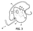
図3は、ボディ14が被験者の気道の一つ以上の外口(例えば、鼻孔、鼻孔及び口等)をカバーするマスクとして形成される呼吸機器10の実施例を示す。図3に示される実施例では、ボディ14は、囲まれる被験者の気道の一つ以上の外口の外部を囲む膜である。更に、ボディ14の膜は、被験者の気道の一つ以上の外口と外気との間に複数の流路を形成する。これらの流路は、吸入ポート20により形成されるボディ14を通る流路と、呼気ポート22により形成されるボディ14を通る流路とを含む。
FIG. 3 shows an embodiment of the
吸入バルブ26は、吸入ポート20内に配置され、外気からのガスが比較的自由にボディ14を通って被験者により吸入可能にする。呼気バルブ28は、呼気ポート22内に配置され、ボディ14により囲まれる被験者の気道の一つ以上の外口からのガスの呼気が、呼気の間、被験者の気道内の圧力が被験者の気道をサポートするレベルまで上昇させるように、ボディ14内から外気へのガスの流れを制限する。図1及び図2に図示される実施例に関して上述されたように、図3に図示される呼吸機器10の実施例は、吸入バルブ26及び/又は呼気バルブ28の一方または両方を吸入ポート20又は呼気ポート28それぞれから取り外し可能にする。更に、一つの実施例では、呼気ポート22のガスの流れに対する抵抗は、操作的な制御により及び/又は呼気バルブ26を異なる抵抗を持つ他のバルブと交換することにより設定可能である。ボディ14が全ての気道開口部をカバーする実施例(例えば、図3に図示される実施例)では、吸入ポート20の一方又は両方が、バックアップ目的のために複製されてもよい。
The
図1及び図2に示される鼻枕構成よりもむしろ、(例えば、図3に図示されるように)マスクのようなボディ14の形成が、付加的な外口を介して供給されるサポートのため(例えば、ここでマスクが鼻孔だけでなく口をカバーする)、及び/又は他の理由のため、感知される快適さのために幾人かの被験者により好まれる。図3に示される呼吸機器10の実施例の動作のメカニズムは、呼気の間、被験者の気道内の圧力を上昇させる図1及び図2に図示される実施例と同一であることが明らかである。呼吸機器10が図1及び図2の鼻枕構成を実行する実施例に関する呼吸機器10の他の態様が後述されるが、これに限定することを目的としていないし、これらの説明は当業者により図3のマスクまで拡張できる。
Rather than the nasal pillow configuration shown in FIGS. 1 and 2, the formation of a
一つの実施例では、マスクは、顔面に対して囲まれている内側ボリュームのデッドスペースを最小化するようにデザインされている。鼻開口部のためのインタフェース室は、圧力障壁又は一方通行バルブにより口のインタフェースから離隔されてもよい。室を離隔することは、圧力封止構造を強化して、及び/又は、被験者が鼻呼吸しているとき、余分な口のデッドスペースで呼気されたガスを再呼吸する苦痛を回避する。 In one embodiment, the mask is designed to minimize the dead space of the inner volume that is surrounded by the face. The interface chamber for the nasal opening may be separated from the mouth interface by a pressure barrier or one-way valve. Separating the chamber enhances the pressure sealing structure and / or avoids the pain of rebreathing the exhaled gas in the extra mouth dead space when the subject is breathing nasally.
一つの実施例では、被験者の鼻橋に位置するボディ14の部分が、被験者の皮膚との安全な封止を形成するように構成されてもよい。例えば、ボディ14のこの区域は、被験者に接着するための接着剤(例えば、ヒドロゲル等)を含む。幾つかの例では、ボディのこの区域は、ボディ14と鼻橋との間の接着力によって、被験者の鼻腔を開いたままにする比較的弾力のある材料から形成される。
In one embodiment, the portion of the
図4は、この開示の一つの実施例による呼吸機器10のブロック図である。図4に示される図において、ボディ14、吸入ポート20、呼気ポート22、吸入バルブ26及び呼気バルブ28に加えて、呼吸機器10は、一つ以上のセンサ30、ユーザインタフェース31及びプロセッサ32を含む。
FIG. 4 is a block diagram of a
センサ30は、(例えば、図1に示され上述のように)呼吸機器10が取り付けられる被験者の気道の安定性に関係する情報を伝達する一つ以上の出力信号を生成するように構成される。一つの実施例では、センサ30は、ボディ10上に担持される。非限定的な例として、センサ30は、被験者の気道で、又はその近くで(例えば、ボディ14内で)のガスの一つ以上のパラメータを監視する。一つ以上のパラメータは、一つ以上の流れ、圧力及び/又は他のパラメータを含む。一つの実施例では、センサ30は、振動を電気的出力信号へ変換するトランスデューサを含む。トランスデューサにより生成される出力信号は、(例えば、「いびきをかいている」)被験者の気道の不安定性により生成される音波の振動、気道不安定性により生じる被験者の気道の周りの組織の振動及び/又は気道不安定性を示す他の振動を変換する。一つの実施例では、センサ30は、ボディ10上に担持されていない。例えば、センサ30は、被験者の呼吸要求、被験者の神経活動及び/又は被験者の気道の状態を示す他のパラメータを監視する一つ以上のセンサを含む。
The
ユーザインタフェース31は、機器10とユーザ(例えば、被験者、介護者、眠っている同行者等)との間のインタフェースを提供し、当該インタフェースを通って、ユーザは、情報を機器10から受けたり、情報を機器10へ供給する。これは、集合的に「情報」と呼ばれるデータ、結果及び/又は命令並びに他の任意の伝達可能なアイテムが、ユーザとプロセッサ32との間で通信可能にされる。ユーザインタフェース31に包含されるのに適しているインタフェース装置の例は、キーパッド、ボタン、スイッチ、キーボード、ノブ、レバー、ディスプレイ画面、タッチスクリーン、スピーカ、マイクロホン、指標照明、可聴警報及びプリンタが挙げられる。
The
有線又は無線の他の通信技術もユーザインタフェース31として本発明により考察されることは、理解されるべきである。例えば、本発明は、ユーザインタフェース31が着脱可能な電気的記録インタフェースと一体化されることを意図する。この例では、情報は、機器10の実行をユーザによりカスタマイズ可能にする着脱可能な記録部(例えば、スマートカード、フラッシュドライブ、リムーバブルディスク等)から、機器10へロードされる。ユーザインタフェース31として機器10の用途に適した他の例示的な入力装置及び技術は、限定されるわけではないが、RS―232ポート、RFリンク、IRリンク、モデム(電話、ケーブル又はその他)を含む。要するに、機器10と情報を通信するための任意の技術が、ユーザインタフェース31として本発明により意図される。
It should be understood that other wired or wireless communication technologies are also contemplated by the present invention as the
プロセッサ32は、呼吸機器10の情報処理機能を供給するように構成される。同様に、プロセッサ32は、デジタルプロセッサ、アナログプロセッサ、情報を処理するように設計されたデジタル回路、情報を処理するように設計されたアナログ回路、状態装置及び/又は情報を電子的に処理するための他のメカニズムの一つ以上を含んでもよい。プロセッサ32が単一の構成要素として図4に示されているが、これは図示目的のためだけである。幾つかの実行において、プロセッサ32は、複数の処理ユニットを含んでもよい。これらの処理ユニットは物理的に同じ装置内に位置されるか、又はプロセッサ32は協調して動作する複数の装置の処理機能を表してもよい。一つの実施例では、プロセッサ32は、ボディ14により担持される。
The
図4に示されているように、一つの実施例では、プロセッサ32は、安定性モジュール34、制御モジュール36、設定モジュール38、被験者監視モジュール39及び/又は他のモジュールを含む。モジュール34、36、38及び/又は39は、ソフトウェア、ハードウェア、ファームウェア、又はソフトウェア、ハードウェア及び/若しくはファームウェアの組み合わせで実行されてもよいし、及び/又は他のやり方で実行されてもよい。モジュール34、36、38及び39が単一の処理ユニット内で共に位置されるように図4に図示されているが、実際にはプロセッサ32が複数の処理ユニットを含んでもよいし、モジュール34、36、38及び/又は39が他のモジュールから離れて位置されてもよいことは、理解されるべきである。更に、種々異なるモジュール34、36、38及び/又は39により供給される機能の説明は、図示目的であって、限定するわけではないが、モジュール34、36又は38は説明されているのより多い機能又は少ない機能を提供してもよい。例えば、モジュール34、36、38及び/又は39の一つ以上が除去され、その機能の一部又は全てがモジュール34、36及び/又は38の他のモジュールにより供給されてもよい。他の例として、プロセッサ32は、モジュール34、36、38及び/又は39の1つに起因する機能の一部又は全てを実施する一つ以上の追加モジュールを含んでもよい。
As shown in FIG. 4, in one embodiment, the
安定性モジュール34は、被験者の気道の安定性を決定するように構成される。被験者の気道の安定性は、センサ30により生成される出力信号に基づいて決定される。一つの実施例では、安定性モジュール34によりなされる被験者の気道の安定性の決定は、既定の閾値を上回る被験者の気道内の不安定性の例の特定を含む。一つの実施例では、安定性モジュール34によりなされる被験者の気道の安定性の決定は、被験者の気道の安定性の測定を含む。
The
図4に図示される呼吸機器10の実施例では、呼気バルブ28は、ボディ14の内部から外気へのガス(例えば、呼気されたガス)の流れに対する制御可能な抵抗を供給するように構成される。制御モジュール36は、ガスのこの流れに対する呼気バルブ28の抵抗を制御するように構成される。とりわけ、制御モジュール36は、安定性モジュール34によりなされる気道安定性の決定に基づいて、ボディ14の内部から外気へのガスの流れに対する呼気バルブ28の抵抗を制御する。例えば、安定性モジュール34は、被験者の気道が開いていて安定であると決定する場合、ボディ14の内部から外気へのガスの流れに対する呼気バルブ28の抵抗は、比較的小さくなるように制御モジュール36により制御され、これにより、ボディ14を通って被験者が自由に呼気することを可能にする。他方では、安定性モジュールは、被験者の気道が不安定になったと決定する場合、ボディ14の内部から外気へ流れるガスに対する呼気バルブ28の抵抗は、呼気の間、被験者の気道内の圧力を増大するために増大され、これにより、被験者の気道を安定させる。呼気バルブ28のこの制御は、特に被験者の気道が安定なとき、被験者に呼吸機器10の快適さを強化する。
In the embodiment of the
一つの実施例では、制御モジュール36は、被験者12の快適さを強調するように設計されているアルゴリズムに従って、ボディ14の内部から外気へのガスの流れに対する呼気バルブ20の抵抗を制御する。例えば、制御モジュール36は、比較的低い初期値に呼気バルブ20の抵抗をセットし、その後時間をかけて治療上の値へ抵抗を逓増させる。これは、被験者を徐々に時間とともに気道の加圧に慣れるようにさせる。幾つかの場合では、これは、患者が、比較的低い抵抗で寝入って、その後寝入った後に治療上の抵抗値で治療上のサポートを受けることを可能にする。一つの実施例では、制御モジュール36は、初期抵抗へ抵抗値を(例えば、ユーザインタフェースを介して)被験者がリセット可能にする。これは、起きるとすぐに、呼気バルブ20の抵抗を被験者が低減可能にし、これによって、被験者が再び寝入ることができるように、被験者の快適さを強化する。
In one embodiment, the
設定モジュール38は、制御モジュール36が気道の安定性の減少に反応する態様を被験者が、少なくともいくぶん構成可能にするように構成される。例えば、設定モジュール38は、被験者が、制御モジュール36の感度を気道不安定性に設定可能にし、気道不安定性を検出すると呼気されたガスに対する呼気バルブ28の抵抗に付与される増加の量を設定可能にし、及び/又は制御モジュール36により制御される呼吸機器10の他のパラメータを設定可能にする。一つの実施例では、設定モジュール38は、ユーザインタフェースを介して被験者にアクセス可能である。ユーザインタフェースは、ボディ14上に担持されるか、又は被験者が設定モジュール38の構成のため他の処理構成要素(例えば、コンピュータ、携帯電話、パーソナル携帯情報機器等)と呼吸機器とを接続する通信ポートを含む。幾つかの場合には、バルブ28は、プロセッサ32から分離すると、バルブ28が開くか又は最大の抵抗設定に戻るように構成される。
The
被験者監視モジュール39は、機器10から治療を受けている被験者を監視するように設定される。特に、被験者監視モジュール39は、睡眠の間、気道閉塞を生じさせる被験者の状況又は症候群の状態を監視する。例えば、閉塞型睡眠時無呼吸症候群(「OSA」)は、変形性(退行性)状態である傾向がある。被験者監視モジュール39は、被験者が受けるOSAの進捗の状態に関して、情報を被験者又は他のユーザに提供するために、被験者を監視する。幾つかの例では、被験者監視モジュールは、(例えば、安定性モジュール34により特定されるような)多くの妨害事象、(例えば、センサ30により生成される出力信号に基づく)機器10を通るガスの流れの一つ以上パラメータ及び/又はOSA若しくは被験者が受ける他の状態の進捗に関係する他の情報の一つ以上を監視する。被験者監視モジュール39は、ユーザインタフェース31を介して、OSA又は被験者が受ける他の状況の状態の指標を被験者に供給する。
The
一つの実施例では、被験者監視モジュール39は、被験者が受ける妨害事象の数に基づいて、毎夜、毎週、毎月又は他の周期でユーザに指標を供給する。例えば、妨害事象の数が既定の閾値を突破する場合、被験者が機器10により現在供給されているもの以外の付加的な気道サポートを必要とするという指標が、ユーザに供給される。
In one embodiment,
一つの実施例では、被験者監視モジュール39は、ユーザインタフェース31を介して、センサ30及び/又は安定性モジュール34からユーザへ獲得されるデータを供給する。ユーザは、その後、OSA又は被験者が受ける他の状況の進捗についての決定をするためにそのデータを実行する。幾つかの例では、被験者監視モジュール39から受けるデータは、例えば、OSA又は被験者が受ける他の状況、被験者の症状及び/又は被験者が受ける妨げられた呼吸の生理的原因を分類する表現型検査を実施するために用いられる。
In one embodiment, the
図4の呼吸機器10に起因している特徴及び機能の少なくとも幾つかが、プロセッサ32のような電気的プロセッサを含まない実施例で実行されてもよいことは、理解されるだろう。非限定的な例として、バルブ28に関して上述の抵抗の漸進的逓増は、バルブ28を通じてガス流を徐々に制限するための機械的機構により(例えば、バルブ28で形成される一つ以上の開口部の直径及び/又は横断面を徐々に制限することにより)達成できる。例えば、メモリポリマーが、バルブ28で形成される一つ以上の開口部に挿入される。メモリポリマーは、(例えば、挿入プラグにより)増大された後に収縮する。バルブ28は、膜/メモリ構造体がリセット機構により最初の開位置に置かれた後、バルブ28と関連した開口部を閉じるために、膜(又は複数の膜)を引っ張るか又は押すメモリ金属/ポリマー/ナノ構造体を含む。バルブ28は、バルブ28でゆっくり開口部を閉じるために膜(又は複数の膜)に対して押圧している、呼吸圧により解除されるばねベースのクロック状機構を含む。バルブ28は、(一定又は予めプログラムされた時間で動作される)バルブ開口部をゆっくり閉じるために、ロッキングラチェットクロック機構を含む。抵抗を逓増するためバルブ28に関連するバルブ開口部をゆっくり閉じるための他の機構も考察されてもよい。
It will be appreciated that at least some of the features and functions resulting from the
一つの実施例では、電気的プロセッサからの制御なしで時間をかけてゆっくり抵抗を逓増させるためにバルブ28に含まれる機械的機構は、発動制御を含む。発動制御は、被験者12により、又は必要に応じて睡眠中被験者12の近くの他の人(例えば、配偶者、親、介護者等)により起動される。
In one embodiment, the mechanical mechanism included in
電子プロセッサによる制御なしに図4に図示される機器10の実施例で達成される機能のタイプの他の例として、呼吸機器10は、バルブ28の抵抗の変化をトリガーするための機械的機構を含む。例えば、バルブ28は、被験者のいびきにより振動させられる共振音容器及び/又は音叉を含む。共振音容器又は音叉は、バルブ28と関連する一つ以上の開口部に制限を生じさせるクロック機構又はリリース機構に結合される。
As another example of the types of functions that can be achieved in the embodiment of the
図5は、呼吸機器10により供給される被験者の気道へのサポートを強化する付加的な特徴を含む呼吸機器10の実施例を例示する。図5に示される実施例では、呼吸機器10は、被験者の気道をサポートするように構成されるシステム40の部品として実行される。一つの実施例では、呼吸機器10に加えて、システム40は、圧力生成器42及び回路44を含む。
FIG. 5 illustrates an embodiment of the
圧力生成器42は、呼吸機器10を介して被験者の気道へ送出のための呼吸可能なガスの圧力がかかった流れを生成するように構成される。圧力生成器42により生成される呼吸可能なガスの圧力がかかった流れの一つ以上のパラメータは、治療目的のため圧力生成器42により制御される。例えば、圧力生成器42は、呼吸可能なガスの圧力がかかった流れの圧力、流率、成分及び/又は他のパラメータの一つ以上を制御する。一つの実施例では、圧力生成器42は、ガス供給源と、当該ガス供給源内のガスから生成されるガスの圧力がかかった流れの流れ及び/又は圧力を制御する一つ以上の部品とを含む。ガス供給源は、例えば、外気、圧力がかかったガスのタンク、壁ガス供給源及び/又は呼吸可能なガスの他のボディのような呼吸可能なガスの任意の供給源(又は、複数の供給源)を含む。ガス供給源からの呼吸ガスは、ガス状の形態(例えば一酸化窒素、霧状等)である空気、酸素、酸素混合物、呼吸ガス及び薬物の混合物のような任意の呼吸可能なガスであったり、及び/又は他の呼吸可能なガスである。呼吸可能なガスの圧力がかかった流れの一つ以上のパラメータを制御する一つ以上の部品は、呼吸可能なガスの圧力がかかった流れの一つ以上のパラメータを制御するためのバルブ、ブロワー、ピストン、送風装置及び/又は他の機構の一つ以上を含む。
The
回路44は、呼吸機器10と圧力生成器42との間にガス流路を形成する。回路44により形成されるガス流路は、圧力生成器42により生成される呼吸可能なガスの圧力がかかった流れを圧力生成器42から呼吸機器10へ送る。図5に示される実施例では、回路44は、圧力生成器42と呼吸機器10との間を走る導管を含む。導管は、可撓性で、圧力生成器42と呼吸機器10との間の流路を外気から実質的に封止する。後述のように、圧力がかかった呼吸可能なガスの流れは、比較的低い流率で呼吸機器10に供給される。このように、回路44の断面積は、比較的小さい。例えば、一つの実施例では、回路44の断面積は、約1cm2未満である。一つの実施例では、回路44の断面積は、約1.5cm2未満である。一つの実施例では、呼吸可能なガスの圧力がかかった流れの低い流率のため、回路44は、比較的可撓性である。回路44の比較的小さな断面サイズ及び/又は回路44の相対的な柔軟性の一方又は両方は、より大きい流率に依存し、送出のため、より大きく及び/又はより固い回路を必要とする圧力サポートシステム(例えば従来のPAPシステム)に関して、システムの有用性を強化する。例えば、より小さな及び/又はより可撓性の回路44は、被験者にとって、より快適である。他の例として、より小さく、より可撓性の回路44は、使用の間、呼吸機器10に転換される引っ張る力及び/又はトルクを減少させる。引っ張る力及び/又はトルクのこの減少は、呼吸機器10及び/又は呼吸機器10を適所に保持する装置(例えば、ヘッドギア)に対するサイズ及び/又は大きさの低減を可能にし、これにより呼吸機器10のより小さな、より観血的でない設計を可能にする。
The
回路44から呼吸可能なガスの圧力がかかった流れを受けるために、図5の図示される実施例では、呼吸機器10のボディ14は、回路44により形成される流路がボディ14の内部と連通される回路ポート46を形成する。一つの実施例では、回路バルブ(図示せず)は、回路ポート46に配置されている。回路バルブは、ボディ14への呼吸可能なガスの圧力がかかった流れの流率を制御する。幾つかの例では、回路バルブの抵抗は、ボディ14への呼吸可能なガスの圧力がかかった流れの流率の調整を可能にするために、制御可能に調節できる。一つの実施例では、呼吸可能なガスの圧力がかかった流れの流率は、圧力生成器42の動作を調整することにより制御される。一つの実施例では、回路バルブは、呼気の間、回路44の下で気流を制御するか又は止めるように設計されている。
In order to receive a flow under pressure of breathable gas from the
一つの実施例では、回路44は回路ポート46から着脱可能であり、呼吸機器10は、回路44が取り外される一方で、回路ポート46を封止するために回路ポート46に着脱自在に挿入できるプラグ(図示せず)を含む。一つの実施例では、プラグを受けるよりはむしろ、回路ポート46内に配置された回路バルブは、外気からのガスが回路ポート46を通ってボディ14に入ることを妨げるために、閉じることができる。外気から回路ポート46を封止することは、回路ポート46に取り付けられている回路44がない場合、呼吸機器10が、上述のように(例えば、図1乃至図4に関して)機能することを可能にする。例えば、被験者は、回路44を通って送られる呼吸可能なガスの圧力がかかった流れにより供給される付加的なサポートなしに、呼吸機器10により供給される気道のサポートを受けたいと欲する。他の例として、被験者が家から離れていて、圧力生成器42及び/又は回路44を運びたくないとき、被験者は、回路44及び圧力生成器42なしで呼吸機器10を使用する。
In one embodiment, the
一つの実施例では、呼吸可能なガスの圧力がかかった流れは、被験者の気道へ付加的なサポートを供給するため、比較的一定の流率で圧力生成器42により生成される。上述されたように、呼吸の間、被験者は、吸入ポート20と被験者インタフェース開口部18との間に形成される流路を介して外気からボディ14を通って自由に吸入する。呼気の間、吸入ポート20は吸入バルブ26により閉じられ、被験者インタフェース開口部18を通って呼気されるガスは、被験者インタフェース開口部18と呼気ポート22との間の流路を介して外気へ排出される。呼気ポート22に取り付けられる呼気バルブ28の抵抗により、呼気されたガスは、気道サポートを供給する、被験者の気道内に圧力を作る。
In one embodiment, a pressurized flow of breathable gas is generated by the
上記のことから理解できるように、回路44及び圧力生成器42なしに呼吸機器が、呼気の間、被験者の気道へサポートを供給する一方、気道は、吸入の間、まだ比較的サポートされていないままである。更に、呼気の間、気道の加圧は、被験者により呼気される空気のボリューム並びに/又は被験者の気道のサイズ及び形状により制限される。このように、圧力生成器42及び回路44のない呼吸機器10の使用は、従来のPAPサポートシステム上で被験者に強化された快適さを提供する一方、呼吸の間、呼吸機器10単独により供給されるサポートが、被験者を適切にサポートするには充分ではない。
As can be appreciated from the above, the respiratory device without
呼吸機器10単独の使用が気道への適切なサポートを被験者に提供しない例では、圧力生成器42及び回路44と一緒の呼吸機器10の使用は、呼吸機器10単独の使用と従来のPAPサポートシステムとの間の中間の治療オプションを供給する。圧力生成器42及び回路44と組み合わせて、呼吸機器10は、あるレベルのサポートを被験者の気道へ供給する一方、被験者が外気から吸入及び外気へ呼気できるように上述のように機能する。回路44を介して呼吸機器10へ送られる呼吸可能なガスの圧力がかかった流れの流率は、吸入の間、受け入れられる最小レベルに気道圧を維持するのに充分大きいだけである。ガスの圧力がかかった流れが、呼吸機器10により被験者の気道へ送られる呼吸可能なガスの主要な源ではないし、(従来のPAPシステムの場合のように)気道サポートの主要な源でもないので、呼吸可能なガスの圧力がかかった流れの流率は比較的低い。例えば、一つの実施例では、呼吸可能なガスの圧力がかかった流れの流率は、約100LPM未満のままである。一つの実施例では、呼吸可能なガスの圧力がかかった流れの流率は、約75LPMより低いままである。一つの実施例では、呼吸可能なガスの圧力がかかった流れの流率は、約50LPMより低いままである。一つの実施例では、呼吸可能なガスの圧力がかかった流れの流率は、約40LPMより低いままである。加圧ガスの比較的低い流率は、より高い流率を必要とするシステム(例えば、従来のPAPシステム)に対して、強化された有用性(例えば、快適さ)を被験者に提供する。
In an example where the use of the
一つの実施例では、呼吸可能なガスの圧力がかかった流れの流率は、使用の間、一貫して供給される比較的静的なパラメータである。被験者に対する流率は、特に被験者のために決定される。例えば、一つの実施例では、睡眠学習の間、一人以上の介護者は、被験者のための適当な流率を決める。一つの実施例では、被験者のための適当な流率は、被験者の気道内の圧力を監視することにより決定される。被験者のための適当な流率は、呼気と吸入との間の遷移で、被験者の気道内の圧力が最小限の遷移気道圧より下に通常ならないことを保証する流率である。最小限の遷移気道圧は、例えば、約4cmH2Oである。 In one embodiment, the rate of flow under pressure of breathable gas is a relatively static parameter that is consistently delivered during use. The flow rate for a subject is determined specifically for the subject. For example, in one embodiment, during sleep learning, one or more caregivers determine an appropriate flow rate for the subject. In one embodiment, the appropriate flow rate for a subject is determined by monitoring the pressure in the subject's airway. A suitable flow rate for a subject is a flow rate that ensures that at the transition between exhalation and inhalation, the pressure in the subject's airway is not usually below a minimum transition airway pressure. The minimum transition airway pressure is, for example, about 4 cmH 2 O.
一つの実施例では、回路44からの呼吸可能なガスの圧力がかかった流れの流率及び/又は圧力は、時間とともにゆっくり増大する。回路44からの呼吸可能なガスの流率及び/又は圧力の徐々の増大は、睡眠の間、効率的な治療のために必要とされるレベルより、被験者のためにより快適である初期レベルから増大してもよい。時間とともに、流率及び/又は圧力のレベルは、効率的な治療を供給するレベルまで増大する。このアプローチは、呼吸可能なガスの圧力及び/又は流率が徐々に増大するので、被験者が呼吸機器10を介して治療のレセプションにゆっくり調整することを可能にする。幾つかの例では、被験者は、圧力及び/又は流率の増大されたレベルに達する前に、寝入りさえする。この実施例では、最初の減少したレベルまで流率及び/又は圧力を「リセットする」制御が、被験者に供給される。例えば、被験者が夜目覚める場合、このリセットは、被験者が再度眠ろうとする一方、被験者が呼吸可能なガスの圧力及び/又は流率のレベルを低下可能にする。
In one embodiment, the flow rate and / or pressure of the pressured flow of breathable gas from
他の実施例では、回路44からの呼吸可能なガスの圧力及び/又は流率は、さもなければ、供給される気道サポートの快適さ及び/又は効力を改良するために変化される。例えば、圧力及び/又は流率は、吸入の間の第1のレベルと呼気の間の第2のレベルとの間に2つのレベルモードによって変化されてもよい。他の例として、圧力及び/又は流率は、上述の単純な増大よりもっと洗練された逓増モードに従って増大されてもよい。
In other embodiments, the pressure and / or flow rate of breathable gas from the
一つの実施例では、呼吸可能なガスの流れの様々なパラメータが、単純な気道サポート以外の治療上の利点を供給するために制御される。例えば、呼吸可能なガスの流れの成分が(例えば、被験者に補足的な酸素を供給するために)制御され、呼吸可能なガスの流れの圧力及び/又は流率が被験者の呼吸パターンを同調させるために(例えば、呼吸レートを低下させるために、呼吸ボリュームを増大させるために等)制御され、及び/又はパラメータが他の治療目的のために制御される。 In one embodiment, various parameters of breathable gas flow are controlled to provide therapeutic benefits other than simple airway support. For example, the component of the breathable gas flow is controlled (eg, to provide supplemental oxygen to the subject) and the pressure and / or flow rate of the breathable gas flow synchronizes the subject's breathing pattern. Controlled (eg, to reduce respiratory rate, increase respiratory volume, etc.) and / or parameters are controlled for other therapeutic purposes.
図6は、この開示の一つの実施例によるシステム40のブロック図である。図6に示される図では、上述のような呼吸機器10、圧力生成器42及び回路44に加えて、システム40は、一つ以上のセンサ48、ユーザインタフェース49及びプロセッサ50を含む。図6に図示される実施例では、回路バルブ52は、回路44からボディ14に入る呼吸可能なガスの圧力がかかった流れの流率を制御するため回路ポート46内に配置される。一つの実施例(図示せず)では、呼吸可能なガスの圧力がかかった流れの流率が、後述する回路バルブ52により供給される流率制御よりはむしろ、又は当該流率制御に加えて、圧力生成器42の制御を通じて調整されてもよいことは、理解されるべきである。
FIG. 6 is a block diagram of a
センサ48は、呼吸機器10が取り付けられる(例えば、図1に示され上述されているように)被験者の気道の安定性に関係する情報を運ぶ一つ以上の出力信号を生成するように構成される。一つの実施例では、センサ48は、ボディ10上に担持される。一つの実施例では、センサ48は、回路44により担持される。非限定的な例として、センサ48は、被験者の気道で又はその近くで(例えば、ボディ14内で)、ガスの一つ以上のパラメータを監視する。一つ以上のパラメータは、流れ、圧力及び/又は他のパラメータの一つ以上を含む。一つの実施例では、センサ48は、振動を電気的出力信号に変換するトランスデューサを含む。トランスデューサにより生成される出力信号は、被験者の気道の不安定性(例えば、「いびき」)により生成される音波の振動、気道不安定性により生じる被験者の気道の周りの組織の振動及び/又は気道不安定性を示す他の振動を変換する。
The
ユーザインタフェース49は、システム40とユーザ(例えば、被験者、介護者、眠りの同行者等)との間にインタフェースを供給するように構成され、当該インタフェースを通じて情報をユーザシステム40へ供給したり、ユーザシステム40から情報を受けたりする。ユーザインタフェース49は、(図4に示されて、上述されている)ユーザインタフェース31と実質的に同じ態様で機能する。一つの実施例では、ユーザインタフェース49は、複数の実際のインタフェースを含む。一つの実施例では、ユーザインタフェース49は、圧力生成器42と関連したインタフェース及び/又は機器10と関連したインタフェースを含む。
The
プロセッサ50は、システム40の情報処理機能を供給するように構成される。このように、プロセッサ50は、デジタルプロセッサ、アナログプロセッサ、情報を処理するように設計されたデジタル回路、情報を処理するように設計されたアナログ回路、状態装置及び/又は情報を電気的に処理するための他の機構の一つ以上を含む。プロセッサ50が単一の構成要素として図6に示されているが、これは図示目的のためだけである。幾つかの実施態様では、プロセッサ50は、複数の処理ユニットを含む。これらの処理ユニットは、同じ装置内に物理的に位置されるか、又はプロセッサ50は、協調して動作する複数の装置の処理機能を表してもよい。一つの実施例では、プロセッサ50は、ボディ14により担持される。一つの実施例では、プロセッサ50は、回路44及び/又は圧力生成器42により担持される。
The
図6に示されているように、一つの実施例では、プロセッサ50は、安定性モジュール54、制御モジュール56、設定モジュール58、被験者監視モジュール59及び/又は他のモジュールを含む。モジュール54、56、58及び/又は59は、ソフトウェア、ハードウェア、ファームウェア、又はソフトウェア、ハードウェア及び/若しくはファームウェアの幾つかの組合せで実行されてもよいし、及び/又はそれ以外で実行されてもよい。モジュール54、56、58及び59は、単一の処理ユニット内で共に配置されるように図6に図示されているが、プロセッサ50が複数の処理ユニットを含む実施形態では、モジュール54、56、58及び/又は59が他のモジュールから離れて位置されてもよいことは、理解されるべきである。更に、モジュール54、56、58及び/又は59の何れかが説明されている以外の多かれ少なかれ機能を供給するので、以下に説明される異なるモジュール54、56、58及び/又は59により供給される機能の説明は、図示目的のためであって、限定する意図はない。例えば、モジュール54、56、58及び/又は59の一つ以上が除去されてもよいし、その機能の一部又は全てがモジュール54、56、58及び/又は59の他のモジュールにより供給されてもよい。他の例として、プロセッサ50は、モジュール54、56、58及び/又は59の1つのモジュールに帰する機能の幾つか又は全てを実施する一つ以上の追加モジュールを含む。
As shown in FIG. 6, in one embodiment, the
安定性モジュール54は、被験者の気道の安定性を決定するように構成される。被験者の気道の安定性は、センサ48により生成される出力信号に基づいて決定される。一つの実施例では、安定性モジュール54によりなされる被験者の気道の安定性の決定は、既定の閾値を上回る被験者の気道の不安定性の例の特定を含む。一つの実施例では、安定性モジュール54によりなされる被験者の気道の安定性の決定は、被験者の気道の安定性の測定を含む。
The
図6に図示されるシステム40の実施例では、制御モジュール56は、回路44からボディ14へ圧力がかかったガスの流れに対する回路バルブ52の抵抗を制御するように構成されている。回路バルブ52のこの抵抗を制御することにより、制御モジュール56は、回路44からボディ14への呼吸可能なガスの圧力がかかった流れの流率を制御する。一つの実施例では、制御モジュール56は、安定性モジュール54によりなされる気道安定性の決定に基づいて、回路バルブ52の抵抗を制御する。例えば、安定性モジュール54は、被験者の気道が開いていて安定であると決定する場合、回路44からボディ14への圧力がかかったガスの流れに対する回路バルブ52の抵抗が、制御モジュール56により比較的大きくなるように制御され、これにより、回路44からボディへの圧力がかかったガスの流れを低減させるか又は止める。他方、安定性モジュール54は被験者の気道が不安定になったと決定する場合、回路バルブ52の抵抗は、圧力がかかったガスが回路44からボディ14を通って被験者の気道へと流れることを許容するために減少され、これにより、吸入の間、被験者の気道を安定させるために被験者の気道内の圧力を増大する。回路バルブ52のこの制御は、特に被験者の気道が安定なとき、被験者にシステム40の快適さを強調する。バルブ52は、圧力源内に含まれる加圧ガス回路内の何処にも配置できる。他の構成は、バルブ52が外気への分路である構成を含む。同様の効果は、例えば、ブロワー速度を制御して、バルブ52なしで得られる。当業者にとって明らかである多くの可能な圧力制御構成がある。
In the embodiment of the
一つの実施例では、制御モジュール56は、回路バルブ52の抵抗を逐次増大及び/又は減少させる。これら逐次の増大及び/又は減少は、安定性モジュール54によって決定されるように、被験者の気道の安定性の逐次の増大及び/又は減少に反応している。一つの実施例では、制御モジュール56は、ガスが既定の流率で回路14からボディ14に流れ込むのを許容する開位置に対応する抵抗と、回路44からのガスの流れが止められるか又は著しく遅くなる閉位置に対応する抵抗との間で、回路バルブ52の抵抗を調整する。一つの実施例では、安定性モジュール54により特定されるように、被験者の気道の不安定化に応答して、制御モジュール56は、回路バルブ52の抵抗を逐次減少させ始め、これにより気道が安定するまで、回路44から被験者の気道へのガスの流れを逐次増大させる。一つの実施例では、回路バルブ52の抵抗体が減少され被験者の気道が安定する場合、制御モジュールは回路バルブ52の抵抗を逐次増大させ、これにより、流れが止められるか若しくは著しく遅くなるか、又は他の不安定化が安定性モジュール54により特定されるまで、回路44から被験者の気道へのガスの流れを逐次減少させる。
In one embodiment, the
一つの実施例では、回路バルブ52の抵抗を制御することに加えて、制御モジュール56は、安定性モジュール54によりなされる被験者の気道の安定性の決定に基づいて、呼気バルブ28の調整可能な抵抗を制御する。例えば、制御モジュール56は、図4を参照して上述された態様で、呼気バルブ28の抵抗を制御する。図6に図示される実施例では、制御モジュール56は、システム40により被験者に供給される治療の一つ以上の態様を強化するために、呼気バルブ28及び回路バルブ52の制御を調整する。非限定的な例として、制御モジュール56は、安定性モジュール54が気道不安定性を特定する場合、被験者の気道を同時にサポートするために、呼気バルブ28の抵抗を増大させ、回路バルブ52の抵抗を減少させる。他の例として、制御モジュール56は、被験者の気道が安定するまで、被験者の気道内の圧力が、バルブの1つの抵抗を最初に調整し(例えば、呼気バルブ28の抵抗を増大させ)、次に他のバルブの抵抗を調整することにより(例えば、回路バルブ52の抵抗を減少させることにより)増大される段階的制御スキームを実行する。
In one embodiment, in addition to controlling the resistance of the
設定モジュール58は、制御モジュール56が気道の安定性の減少に反応する態様を被験者が少なくともいくらか設定可能にするように構成される。例えば、設定モジュール58は、被験者が、気道不安定性に対する制御モジュール56の感度、検出された気道不安定性に応じて呼気されるガスに対する呼気バルブ28の抵抗に適用される増大の量、検出された気道不安定性に応じて回路バルブ52の抵抗に適用される減少の量を設定し、及び/又は制御モジュール56により制御されるシステム40の他のパラメータ(例えば、圧力生成器42のパラメータ等)を設定可能にする。一つの実施例では、設定モジュール58は、ユーザインタフェースを介して被験者にアクセス可能である。ユーザインタフェースは、ボディ14上に担持されるか、又は通信ポートを含み、当該通信ポートを介して被験者は、設定モジュール58の構成のため他の処理構成要素(例えば、コンピュータ、携帯電話、パーソナル携帯情報機器等)とシステム40とを接続する。
The
被験者監視モジュール59は、OSAの状態又は被験者がかかる他の状態を監視し、ユーザインタフェース49を介してユーザにこの監視結果を提供するように構成される。一つの実施例では、被験者監視モジュール59は、被験者監視モジュール39と実質的に同じ態様で動作する。一つの実施例では、被験者監視モジュール39により得られ及び/又は生成される情報は、制御モジュール56が、ガスを呼吸機器10に送る際、圧力生成器42及び/又は回路バルブ52を制御する態様を決定するために制御モジュール56により実行される。
The
一つの実施例では、プロセッサ50は、システム40の外部の一つ以上の治療システムと通信する一つ以上のモジュールを含む。これらのモジュールは、プロセッサ50により制御される治療の態様が、一つ以上の外部システムにより被験者に供給される治療と調整されることを保証するように機能する。例えば、システム40により供給される治療は、不眠症治療、疼痛管理治療、診断用装置及び/若しくはシステム、照明治療、薬物の投与、並びに/又はシステム40により供給される気道サポート及び/若しくは圧力により強化若しくは妨げられる他の治療及び/若しくは診断の一つ以上と調整される。
In one embodiment, the
図7は、ボディ14が被験者12の鼻孔を囲み、回路44からボディ14へ送られる呼吸可能なガスの圧力がかかった流れが鼻孔の一つだけ(又は、実質的に一つだけ)に供給されるシステム40の実施例の線図である。幾つかの例では、鼻孔の1つに呼吸可能なガスの圧力がかかった流れを供給するだけに加えて、呼吸機器10は、ガスが鼻孔の一方と外気との間に流れ、この流れは鼻孔の他方と外気との間の流れとは異なる抵抗で流れるように構成される。
FIG. 7 shows that the
より詳しくは、ボディ14は、回路ポート52から被験者インタフェース開口部18の単一の開口部への単一の流路を形成するように構成される。この単一の流路を形成するために、ボディ14は、他の被験者インタフェース開口部への圧力がかかったガスの流れのアクセスを阻止する一方、回路ポート52から被験者インタフェース開口部18の単一の開口部への圧力がかかったガスの流れをガイドするガスの流れに対する一つ以上の内部障壁60を含む。内部障壁60が単一の通さない障壁として図7に図示されているが、これは限定する意図はない。一つの実施例では、複数の障壁部材は、本願では内部障壁60に起因する機能を実施する。一つの実施例では、内部障壁60は、流路の間のガスの流れを封止せず、代わりに流路の間のアクセスを制限する。一つの実施例では、内部障壁60は、ボディ14内に形成される流路の間で一方向へガスが流れることを可能にする一方向バルブを含む。
More particularly, the
一般に、被験者12は、回路44から被験者12の気道への呼吸可能なガスの圧力がかかった流れの供給が目立っていることを見つける。回路44から被験者12の鼻孔の一方への呼吸可能なガスの圧力がかかった流れを方向づけることにより、当該流れのこの目立ちは、被験者12の気道を加圧する利点を依然供給する一方で、低減される。例えば、回路44から被験者12の鼻孔の一方へガスの流れを供給するだけにより、回路44からのガスの流れのため被験者12により経験される鼻腔内の冷たさ及び/又は乾燥は、鼻孔の他方を通る呼気及び/又は吸入が、鼻腔の両方に暖かさ及び/又は湿気を供給するので、低減される。他の例として、回路44から被験者12の鼻孔の一方のみへのガスの流れの方向は、気流に逆らった呼吸と関連する聞こえるノイズを低減する。
In general, subject 12 finds a noticeable supply of breathable gas pressure from
図7で分かるように、一つの実施例では、内部障壁60は、ボディ14内に形成された流路の第1のサブセットが、外気と被験者インタフェース開口部18の一つとの間でガスを通気させ、ボディ14内に形成された流路の第2のサブセットが外気と他の被験者インタフェース開口部との間でガスを通気させるように、被験者インタフェース開口部18と外気との間でガスを通気させる流路を離隔する。内部障壁60により作られる分離は、流路の第2のサブセットから、流路の第1のサブセットを効果的に封止する。
As can be seen in FIG. 7, in one embodiment, the
上述されたように、回路44は回路ポート46から着脱可能であり、回路ポート46は(例えば、回路バルブ52、ストッパー等により)閉じられる。回路44が外され回路ポート46が閉じられる場合、呼吸機器10は、被験者12の鼻孔から外気へのボディ14内のガスの流れに対する流路の第1のサブセット及び流路の第2のサブセットの抵抗のおかげで、呼気の間、被験者12の気道へサポートを供給する。
As described above, the
一つの実施例では、流路の第1のサブセットは、被験者インタフェース開口部18から外気へのガスの流れ及び外気から被験者インタフェース開口部18へのガスの流れに対する、流路の第2のサブセットと同じ累積的な抵抗を持つ。一つの実施例では、流路の第1のサブセットは、被験者インタフェース開口部18から外気へのガスの流れ及び/又は外気から被験者インタフェース開口部18へのガスの流れに対する、流路の第2のサブセットと異なる累積的な抵抗を持つ。
In one embodiment, the first subset of channels is a second subset of channels for the flow of gas from the
例えば、ある構成では、流路(すなわち、回路44からガスの流れを受け取らない流路)の第2のサブセットに対応する吸入ポート20は、完全に阻止される。この構成では、流路の第2のサブセットと連通する鼻孔は、対応する呼気ポート22を通ってボディ14からガスを呼気するが、吸入の間、ガスを受けない。結果として、被験者12は、流路の第1のサブセットからガスを受ける鼻孔だけを通って吸入することを強制され、これは流路の第1のサブセットに供給される呼吸可能なガスの圧力がかかった流れにより供給される気道のサポートを強化する。
For example, in some configurations, the
ある構成では、流路の第2のサブセットに対応する呼気ポート22は、完全に阻止される。この構成では、流路の第2のサブセットと連通する鼻孔は、対応する吸入ポート20を通って外気からガスを吸入する。しかしながら、呼気の間、回路44からガスの流れを受ける鼻孔だけが、対応する呼気バルブを経由してボディ14を通って外気へガスを呼気する。
In some configurations, the
個別に鼻の左右の側に適用される抵抗のこの個々の能動制御は、鼻循環を考慮するとき有利である。例えば、非常に低い呼気の抵抗が、高い固有の鼻抵抗のため既に限られた流れを持つ側にセットできる。反対側は、呼気の間、より高いバルブ抵抗を持つことができる。鼻抵抗を推定して追跡するアルゴリズムは、このように患者への快適さを最大にするために使用できる。 This individual active control of resistance applied individually to the left and right sides of the nose is advantageous when considering nasal circulation. For example, a very low exhalation resistance can be set on the side already having limited flow due to the high intrinsic nasal resistance. The other side can have a higher valve resistance during exhalation. Algorithms that estimate and track nasal resistance can thus be used to maximize patient comfort.
図8は、被験者が呼吸するとき、被験者の気道をサポートする方法62を例示する。以下に提示される方法62の動作は、例示であることを意図する。幾つかの実施例では、方法62は、説明されていない一つ以上の付加的な動作で、及び/又は説明されている動作の一つ以上がなくて達成されてもよい。加えて、方法62の動作が図8に図示され以下に説明される順番は、制限することを意図しない。方法62の動作が、(図1乃至図7に示されて、上述された)呼吸機器10と同じ又は同様である呼吸機器の部品を参照して以下に説明されるが、これは制限することを意図しない。方法62は、この開示の要旨を逸脱しない範囲で様々な他の状況で実行されてもよい。
FIG. 8 illustrates a
動作64では、被験者の気道の一つ以上の外口が囲まれる。被験者の気道の一つ以上の外口は、気道の一つ以上の外口と外気との間に複数の流路を形成するボディで囲まれる。複数の流路は、当該複数の流路の全てではないが一つ以上の流路で作られる流路の第1のサブセットを含む。一つの実施例では、ボディは、(図1乃至図7に示されて上述された)ボディ14と同じか又は類似している。
In
動作66では、被験者による吸入の間、外気から気道の一つ以上の外口へボディを通るガスの流れに対する複数の流路内のガスの流れに対する第1の累積的な抵抗が供給される。第1の累積的な抵抗は、外気から、実質的に妨げられずに気道の一つ以上の外口へ吸入されるのに充分低い。一つの実施例では、動作66は、(図1乃至図7に示されて上述された)吸入バルブ26と同じ又は類似している一つ以上の吸入バルブにより、少なくとも部分的に実行される。
In
動作68では、被験者による呼気の間、気道の一つ以上の外口から外気へのボディを通るガスの流れに対する複数の流路のガスの流れに対する第2の累積的な抵抗が供給される。ガスの流れに対する第2の累積的な抵抗は、ボディにより形成される複数の流路内の他の流路を通るガスの流れを制限することなく、流路の第1のサブセットを通るガスの流れを制限して供給される。第2の累積的な抵抗は、高い圧力が被験者の気道をサポートするように、ボディを通って呼気されるガスが被験者の気道内の圧力を上昇させるのに充分高い。一つの実施例では、動作68は、吸入バルブによって少なくとも部分的に実行される。複数の流路内の他の流路は、(図1乃至図7に示されて上述された)呼気バルブ28と同じか又は類似している一つ以上の呼気バルブを含む。
In
動作70では、第2の累積的な抵抗が調整される。一つの実施例では、第2の累積的な抵抗は、一つ以上の呼気バルブの制御を操作することにより、及び/又は一つ以上の呼気バルブを異なる抵抗のバルブと交換することにより調整される。
In
図9は、被験者が呼吸するとき、被験者の気道をサポートする方法72を例示する。以下に提示される方法72の動作は、例示であることを意図する。幾つかの実施例では、方法72は、説明されていない一つ以上の付加的な動作で、及び/又は説明されている動作の一つ以上がなくて達成されてもよい。加えて、方法72の動作が図9に図示され以下に説明される順番は、制限することを意図しない。方法72の動作が、(図5乃至図7に示されて、上述された)システム40と同じ又は同様である呼吸機器の部品を参照して以下に説明されるが、これは制限することを意図しない。方法72は、この開示の要旨を逸脱しない範囲で様々な他の状況で実行されてもよい。
FIG. 9 illustrates a
動作74では、被験者の気道の一つ以上の外口が囲まれる。被験者の気道の一つ以上の外口は、気道の一つ以上の外口と外気との間に複数の流路を形成するボディで囲まれる。複数の流路は、当該複数の流路の全てではないが一つ以上の流路で作られる流路の第1のサブセットを含む。一つの実施例では、ボディは、(図5乃至図7に示されて上述された)ボディ14と同じか又は類似している。
In
動作76で、呼吸可能なガスの圧力がかかった流れの源は、被験者の気道の囲まれた一つ以上の外口と流体連通して置かれる。一つの実施例では、呼吸可能なガスの圧力がかかった流れの源は、(図5乃至図7に示されて上述された)圧力生成器42と同じか又は類似している圧力生成器である。一つの実施例では、動作76は、(図5乃至図7に示されて上述された)回路44及び回路ポート46と同じか又は類似している回路及び回路ポートにより実施される。
In
動作78では、被験者による吸入の間、外気から気道の一つ以上の外口へボディを通るガスの流れに対する複数の流路内のガスの流れに対する第1の累積的な抵抗が供給される。第1の累積的な抵抗は、外気から、実質的に妨げられずに気道の一つ以上の外口へ吸入されるのに充分低い。一つの実施例では、動作78は、(図1乃至図7に示されて上述された)吸入バルブ26と同じ又は類似している一つ以上の吸入バルブにより、少なくとも部分的に実行される。
In
動作80では、被験者による呼気の間、気道の一つ以上の外口から外気へのボディを通るガスの流れに対する複数の流路のガスの流れに対する第2の累積的な抵抗が供給される。ガスの流れに対する第2の累積的な抵抗は、ボディにより形成される複数の流路内の他の流路を通るガスの流れを制限することなく、流路の第1のサブセットを通るガスの流れを制限して供給される。第2の累積的な抵抗は、高い圧力が被験者の気道をサポートするように、ボディを通って呼気されるガスが被験者の気道内の圧力を上昇させるのに充分高い。一つの実施例では、動作80は、吸入バルブによって少なくとも部分的に実行される。複数の流路内の他の流路は、(図1乃至図7に示されて上述された)呼気バルブ28と同じか又は類似している一つ以上の呼気バルブを含む。
In
動作82では、呼吸可能なガスの圧力がかかった流れが生成される。一つの実施例では、動作82は圧力生成器により実施される。
In
動作84では、呼吸可能なガスの圧力がかかった流れは、被験者の気道の一つ以上の囲まれた開口部に送られる。被験者の気道の一つ以上の外口へ呼吸可能なガスの圧力がかかった流れの送出は、圧力生成器から呼吸可能なガスの流れを運ぶステップと、運ばれた呼吸可能なガスの流れを受けるステップと、被験者の気道の一つ以上の外口に呼吸可能なガスの流れを向けるステップとを含む。一つの実施例では、動作84は、(図5乃至図7に示されて上述された)呼吸機器10及び回路44と同じか又は類似している呼吸機器及び回路により実施される。
In
一つの実施例では、被験者の気道の囲まれた一つ以上外口は、被験者の鼻孔を有する。この実施例では、動作84は、呼吸可能なガスの圧力がかかった流れが被験者の他方の鼻孔に到達することを封止する一方、回路から被験者の鼻孔の一方へ呼吸可能なガスの圧力がかかった流れを向けるステップを有する。動作84のこの部分は、(図7に示されて上述された)内部障壁60と同じか又は類似している呼吸機器内の内部障壁により実施される。
In one embodiment, one or more outer mouths surrounded by the subject's airways have the subject's nostrils. In this example,
図10は、被験者が呼吸するとき、被験者の気道をサポートする方法86を例示する。以下に提示される方法86の動作は、例示であることを意図する。幾つかの実施例では、方法86は、説明されていない一つ以上の付加的な動作で、及び/又は説明されている動作の一つ以上がなくて達成されてもよい。加えて、方法86の動作が図10に図示され以下に説明される順番は、制限することを意図しない。方法86の動作が、(図4及び図6に示されて、上述された)システム40と同じ又は同様である呼吸機器の部品を参照して以下に説明されるが、これは制限することを意図しない。方法86は、この開示の要旨を逸脱しない範囲で様々な他の状況で実行されてもよい。
FIG. 10 illustrates a
動作88では、被験者の気道の一つ以上の外口が囲まれる。被験者の気道の一つ以上の外口は、気道の一つ以上の外口と外気との間に複数の流路を形成するボディで囲まれる。複数の流路は、当該複数の流路の全てではないが一つ以上の流路で作られる流路の第1のサブセットを含む。一つの実施例では、ボディは、(図4及び図6に示されて上述された)ボディ14と同じか又は類似している。
In
動作90では、外気内のガスは、被験者が囲まれた一つ以上の外口を通って自由に吸入できるように、比較的ほとんど抵抗なしに囲まれた一つ以上の外口に到達可能にされる。一つの実施例では、動作90は、(図4及び図6に示されて上述された)吸入バルブと同じか又は類似している一つ以上の吸入バルブにより実施される。
In
動作92では、被験者の気道の安定性に関係する情報を運ぶ一つ以上の出力信号が生成される。一つの実施例では、動作92は、(図4及び図6に示されて上述された)センサ30と同じか又は類似している一つ以上のセンサにより実施される。
In
動作94では、被験者の気道をサポートする治療の1つ以上のパラメータが、動作92で生成される出力信号に基づいて調整される。一つ以上のパラメータは、例えば、ガスが被験者の気道の囲まれた一つ以上外口から外気へ通気される一つ以上の流路のガスの流れに対する抵抗を含む。一つ以上のパラメータは、非限定的な例として、被験者の気道の一つ以上の外口に供給されるガスの圧力がかかった流れのパラメータ(例えば、流率、圧力等)を含む。一つの実施例では、動作94は、(図4及び図6に示されて上述された)呼気バルブ28と同じか又は類似している一つ以上の呼気バルブを制御する(図4及び図6に示されて上述された)プロセッサ32又はプロセッサ50と同じか又は類似しているプロセッサ、(図6に示されて上述された)回路バルブ52と同じか又は類似している一つ以上の回路バルブ、及び/又は(図6に示されて上述された)圧力生成器42と同じか又は類似している圧力生成器により実施される。
In
気道サポートの目的のために被験者の気道内に高い圧力を供給するような上述のシステム及び方法が、説明されてきた。これは、限定的であると見られてはならない。当業者は、本願で説明されているシステム及び方法が同様に他の治療目的のため気道内の圧力を上昇させるために実施されてもよいことを理解するだろう。例えば、吸入と呼気との間の抵抗差を介して被験者の気道内の圧力を制御することは、呼吸機能を最大にし、呼吸時に肺胞の増大された量を得て、肺内の液体増強を減少若しくは遅延させて、及び/又は他の治療利点を供給することにより、急性肺水腫を発見し及び/又は治療するために実行されてもよい。 The above-described systems and methods have been described that provide high pressure in the subject's airways for the purpose of airway support. This should not be seen as limiting. One skilled in the art will appreciate that the systems and methods described herein may be implemented to increase pressure in the airways for other therapeutic purposes as well. For example, controlling the pressure in the subject's airway via the resistance difference between inhalation and expiration maximizes respiratory function, gains increased volume of alveoli during breathing, and enhances fluid in the lungs May be implemented to detect and / or treat acute pulmonary edema by reducing or delaying and / or providing other therapeutic benefits.
本発明は最も実際的であり好ましい実施例であると現在考えられているものに基づいて、例示目的のため詳細に説明されてきたが、斯様な詳細は単に例示目的であり、本発明は開示された実施例に限定されず、これに反して、添付の請求の範囲内にある変更及び等価なアレンジメントをカバーする意図があることは、理解されるべきである。例えば、本発明は、可能な限り、任意の実施例の一つ以上の特徴が他の任意の実施例の一つ以上の特徴と組み合わせられることも考察することは、理解されるべきである。 Although the present invention has been described in detail for purposes of illustration based on what is presently considered to be the most practical and preferred embodiment, such details are merely for illustrative purposes and the present invention is It is to be understood that the invention is not limited to the disclosed embodiments, but on the contrary is intended to cover modifications and equivalent arrangements that fall within the scope of the appended claims. For example, it is to be understood that the present invention contemplates that, where possible, one or more features of any embodiment may be combined with one or more features of any other embodiment.
Claims (19)
Applications Claiming Priority (3)
| Application Number | Priority Date | Filing Date | Title |
|---|---|---|---|
| US14125008P | 2008-12-30 | 2008-12-30 | |
| US61/141,250 | 2008-12-30 | ||
| PCT/IB2009/055626 WO2010076711A1 (en) | 2008-12-30 | 2009-12-09 | System and respiration appliance for supporting the airway of a subject |
Publications (3)
| Publication Number | Publication Date |
|---|---|
| JP2012513805A JP2012513805A (en) | 2012-06-21 |
| JP2012513805A5 JP2012513805A5 (en) | 2013-01-31 |
| JP5723785B2 true JP5723785B2 (en) | 2015-05-27 |
Family
ID=41786223
Family Applications (1)
| Application Number | Title | Priority Date | Filing Date |
|---|---|---|---|
| JP2011542949A Active JP5723785B2 (en) | 2008-12-30 | 2009-12-09 | System, method and respiratory device for supporting a subject's airway |
Country Status (7)
| Country | Link |
|---|---|
| US (1) | US8844531B2 (en) |
| EP (1) | EP2384173B1 (en) |
| JP (1) | JP5723785B2 (en) |
| CN (1) | CN102271631B (en) |
| BR (1) | BRPI0918342A2 (en) |
| RU (1) | RU2527158C2 (en) |
| WO (1) | WO2010076711A1 (en) |
Families Citing this family (49)
| Publication number | Priority date | Publication date | Assignee | Title |
|---|---|---|---|---|
| US7588033B2 (en) | 2003-06-18 | 2009-09-15 | Breathe Technologies, Inc. | Methods, systems and devices for improving ventilation in a lung area |
| EP1660004A4 (en) | 2003-08-18 | 2017-05-31 | Breathe Technologies, Inc. | Method and device for non-invasive ventilation with nasal interface |
| CA2623756A1 (en) | 2005-09-20 | 2007-03-29 | Lutz Freitag | Systems, methods and apparatus for respiratory support of a patient |
| WO2007142812A2 (en) | 2006-05-18 | 2007-12-13 | Breathe Technologies, Inc. | Tracheotomy method and device |
| WO2008019102A2 (en) | 2006-08-03 | 2008-02-14 | Breathe Technologies, Inc. | Methods and devices for minimally invasive respiratory support |
| WO2008144589A1 (en) | 2007-05-18 | 2008-11-27 | Breathe Technologies, Inc. | Methods and devices for sensing respiration and providing ventilation therapy |
| CA2700878C (en) | 2007-09-26 | 2018-07-24 | Breathe Technologies, Inc. | Methods and devices for providing inspiratory and expiratory flow relief during ventilation therapy |
| JP5513392B2 (en) | 2007-09-26 | 2014-06-04 | ブリーズ・テクノロジーズ・インコーポレーテッド | Method and apparatus for treating sleep apnea |
| WO2009151791A2 (en) | 2008-04-18 | 2009-12-17 | Breathe Technologies, Inc. | Methods and devices for sensing respiration and controlling ventilator functions |
| US8770193B2 (en) | 2008-04-18 | 2014-07-08 | Breathe Technologies, Inc. | Methods and devices for sensing respiration and controlling ventilator functions |
| US8677999B2 (en) | 2008-08-22 | 2014-03-25 | Breathe Technologies, Inc. | Methods and devices for providing mechanical ventilation with an open airway interface |
| US10252020B2 (en) | 2008-10-01 | 2019-04-09 | Breathe Technologies, Inc. | Ventilator with biofeedback monitoring and control for improving patient activity and health |
| US9027553B2 (en) * | 2008-12-30 | 2015-05-12 | Koninklijke Philips N.V. | System and respiration appliance for supporting the airway of a subject |
| AU2009334353B2 (en) * | 2008-12-30 | 2015-02-12 | Koninklijke Philips Electronics, N.V. | System and respiration appliance for supporting the airway of a subject |
| US9216266B2 (en) * | 2008-12-30 | 2015-12-22 | Koninklijke Philips N.V. | System and respiration appliance for supporting the airway of a subject |
| US9132250B2 (en) | 2009-09-03 | 2015-09-15 | Breathe Technologies, Inc. | Methods, systems and devices for non-invasive ventilation including a non-sealing ventilation interface with an entrainment port and/or pressure feature |
| CA2757588C (en) | 2009-04-02 | 2017-01-03 | Breathe Technologies, Inc. | Methods, systems and devices for non-invasive open ventilation with gas delivery nozzles in free space |
| US9962512B2 (en) | 2009-04-02 | 2018-05-08 | Breathe Technologies, Inc. | Methods, systems and devices for non-invasive ventilation including a non-sealing ventilation interface with a free space nozzle feature |
| CN102762250B (en) | 2009-09-03 | 2017-09-26 | 呼吸科技公司 | Mthods, systems and devices for including the invasive ventilation with entrainment port and/or the non-tight vented interface of pressure characteristic |
| US20130102917A1 (en) * | 2010-07-02 | 2013-04-25 | Michael Edward Colbaugh | System and method for performing respiratory diagnostics |
| AU2011292111B2 (en) | 2010-08-16 | 2015-03-26 | Breathe Technologies, Inc. | Methods, systems and devices using LOX to provide ventilatory support |
| WO2012045051A1 (en) | 2010-09-30 | 2012-04-05 | Breathe Technologies, Inc. | Methods, systems and devices for humidifying a respiratory tract |
| GB2500145B (en) * | 2010-12-03 | 2016-11-02 | Fisher & Paykel Healthcare Ltd | Apparatus for supplying gases |
| US9597479B2 (en) * | 2011-02-11 | 2017-03-21 | Redmed Limited | Method and apparatus for treatment of sleep disorders |
| US9987444B2 (en) | 2011-07-01 | 2018-06-05 | Koninklijke Philips N.V. | System and method for limited flow respiratory therapy |
| EP3539605B1 (en) * | 2012-03-05 | 2021-09-15 | Keepmed Ltd | System to facilitate breathing of a subject |
| US9333318B2 (en) | 2012-04-13 | 2016-05-10 | Fresca Medical, Inc. | Sleep apnea device |
| US10307562B2 (en) | 2012-04-13 | 2019-06-04 | Fresca Medical, Inc. | Auto-feedback valve for a sleep apnea device |
| US9492086B2 (en) | 2012-03-21 | 2016-11-15 | Fresca Medical, Inc. | Apparatus, systems, and methods for treating obstructive sleep apnea |
| US10272226B2 (en) | 2012-04-13 | 2019-04-30 | Fresca Medical, Inc. | Auto-feedback valve for a sleep apnea device |
| US20150297849A1 (en) * | 2012-08-03 | 2015-10-22 | Koninklijke Philips N.V. | An apparatus and a method for supporting an airway of a subject |
| CN104717999A (en) * | 2012-08-03 | 2015-06-17 | 皇家飞利浦有限公司 | An apparatus and a method for supporting an airway of a subject |
| BR102012020935B1 (en) * | 2012-08-21 | 2017-06-13 | Alberto Cortez Antonio | snoring deterrent system and the like |
| CN103006366B (en) * | 2012-11-23 | 2015-01-28 | 宁波宏搏高科医疗器械有限公司 | Novel nose breathing device |
| EP2968806A4 (en) * | 2013-03-13 | 2016-12-07 | Ge Sleeping Tech Ltd | Method and system for breathing modulation |
| US9517318B2 (en) | 2013-06-28 | 2016-12-13 | L'Air Liquide, Société Anonyme pour l'Etude et l'Exploitation des Procédés Georges Claude | Method of delivering medical gases via a nasal cannula assembly with flow control passage communicating with a deformable reservoir |
| US9566407B2 (en) | 2013-06-28 | 2017-02-14 | L'Air Liquide, Société Anonyme pour l'Etude et l'Exploitation des Procédés Georges Claude | Nasal cannula assembly with flow control passage communicating with a deformable reservoir |
| US9522248B2 (en) | 2013-06-28 | 2016-12-20 | L'Air Liquide, Société Anonyme pour l'Etude et l'Exploitation des Procédés Georges Claude | Breathing assistance apparatus for delivery of nitric oxide to a patient by means of a nasal cannula assembly with flow control passage |
| US9492626B2 (en) * | 2013-06-28 | 2016-11-15 | L'Air Liquide, Société Anonyme pour l'Etude et l'Exploitation des Procédés Georges Claude | Breathing assistance assemblies suitable for long term no therapy |
| US9486600B2 (en) | 2013-06-28 | 2016-11-08 | L'Air Liquide, Société Anonyme pour l'Etude et l'Exploitation des Procédés Georges Claude | Nasal cannula assembly with inhalation valves communicating with a deformable reservoir |
| US9522247B2 (en) | 2013-06-28 | 2016-12-20 | L'Air Liquide, Société Anonyme pour l'Etude et l'Exploitation des Procédés Georges Claude | Method of treating a patient having pulmonary hypertension by long term NO therapy |
| CN106029142B (en) | 2014-02-19 | 2019-06-18 | 皇家飞利浦有限公司 | For inverse double positive airway pressure challenges of respiratory disorder diagnosis |
| CA2963229A1 (en) | 2014-10-03 | 2016-04-07 | Aut University | A method and apparatus for the controlled delivery of gases |
| EP3277351B1 (en) | 2015-04-02 | 2019-06-05 | Hill-Rom Services PTE. LTD. | Manifold for respiratory device |
| US10322252B2 (en) * | 2015-07-10 | 2019-06-18 | Darin B Atherton | Ergonomic nasal cannula |
| US10960163B2 (en) * | 2016-09-02 | 2021-03-30 | Fresca Medical Inc. | Apparatus, systems, and methods for improved treatment of obstructive sleep apnea |
| US11771860B2 (en) | 2017-06-13 | 2023-10-03 | Maquet Critical Care Ab | Nasal patient interface arrangement, breathing apparatus, and method for operating a breathing apparatus |
| US10792449B2 (en) | 2017-10-03 | 2020-10-06 | Breathe Technologies, Inc. | Patient interface with integrated jet pump |
| CN109303960B (en) * | 2018-10-26 | 2020-11-03 | 北京怡和嘉业医疗科技股份有限公司 | Ventilation treatment equipment and control method |
Family Cites Families (19)
| Publication number | Priority date | Publication date | Assignee | Title |
|---|---|---|---|---|
| US3777757A (en) * | 1971-01-08 | 1973-12-11 | R Gray | Sucking wound plug and chest aspirator |
| SE466941B (en) * | 1989-06-27 | 1992-05-04 | Bjoern Wennerholm | DEVICE FOR RESPIRATORY MONITORING AND TEMPORARY RESPIRATORY ASSISTANCE FOR SNACK PROBLEMS DURING SLEEPING AND ULTIMATING OBSTRUCTIVE SLEEPING |
| US5239995A (en) * | 1989-09-22 | 1993-08-31 | Respironics, Inc. | Sleep apnea treatment apparatus |
| US5906203A (en) * | 1994-08-01 | 1999-05-25 | Safety Equipment Sweden Ab | Breathing apparatus |
| IL114022A0 (en) | 1995-06-06 | 1995-10-31 | Pastel Manag Ltd | A respiration device |
| GB9904906D0 (en) * | 1999-03-03 | 1999-04-28 | Djupesland Per G | Device |
| US6723055B2 (en) * | 1999-04-23 | 2004-04-20 | Trustees Of Tufts College | System for measuring respiratory function |
| US6626175B2 (en) * | 2000-10-06 | 2003-09-30 | Respironics, Inc. | Medical ventilator triggering and cycling method and mechanism |
| US7335181B2 (en) * | 2000-12-26 | 2008-02-26 | Pulmonox Technologies Corporation | Nitric oxide decontamination of the upper respiratory tract |
| US20030168057A1 (en) * | 2001-12-14 | 2003-09-11 | Inhale Therapeutic Systems, Inc. | Electronically controllable aerosol delivery |
| GB0207422D0 (en) | 2002-03-28 | 2002-05-08 | Optinose As | Nasal devices |
| US8584676B2 (en) * | 2003-11-19 | 2013-11-19 | Immediate Response Technologies | Breath responsive filter blower respirator system |
| SE528487C2 (en) * | 2004-11-11 | 2006-11-28 | Transunit Ab | Expiratory pressure regulator |
| US8985116B2 (en) * | 2006-06-07 | 2015-03-24 | Theravent, Inc. | Layered nasal devices |
| US7588032B2 (en) * | 2004-12-08 | 2009-09-15 | Be Intellectual Proeprty, Inc. | Oxygen conservation system for commercial aircraft |
| US20080078393A1 (en) * | 2005-11-22 | 2008-04-03 | General Electric Company | Respiratory monitoring with cannula receiving respiratory airflows, differential pressure transducer, and ventilator |
| AU2006348403A1 (en) * | 2005-12-14 | 2008-05-22 | Mergenet Medical Inc. | High flow therapy device |
| WO2007146189A2 (en) | 2006-06-07 | 2007-12-21 | Ventus Medical, Inc. | Nasal respiratory devices for positive end-expiratory pressure |
| US20070283952A1 (en) * | 2006-06-13 | 2007-12-13 | Mark Wilbur | Pressure sensing in masks |
-
2009
- 2009-12-09 BR BRPI0918342A patent/BRPI0918342A2/en not_active Application Discontinuation
- 2009-12-09 US US13/140,062 patent/US8844531B2/en active Active
- 2009-12-09 RU RU2011132088/14A patent/RU2527158C2/en not_active IP Right Cessation
- 2009-12-09 EP EP09796816.8A patent/EP2384173B1/en active Active
- 2009-12-09 WO PCT/IB2009/055626 patent/WO2010076711A1/en active Application Filing
- 2009-12-09 JP JP2011542949A patent/JP5723785B2/en active Active
- 2009-12-09 CN CN2009801535364A patent/CN102271631B/en active Active
Also Published As
| Publication number | Publication date |
|---|---|
| RU2527158C2 (en) | 2014-08-27 |
| CN102271631B (en) | 2013-12-04 |
| EP2384173A1 (en) | 2011-11-09 |
| EP2384173B1 (en) | 2013-07-17 |
| BRPI0918342A2 (en) | 2016-08-23 |
| JP2012513805A (en) | 2012-06-21 |
| RU2011132088A (en) | 2013-02-10 |
| US8844531B2 (en) | 2014-09-30 |
| US20120227742A1 (en) | 2012-09-13 |
| WO2010076711A1 (en) | 2010-07-08 |
| CN102271631A (en) | 2011-12-07 |
Similar Documents
| Publication | Publication Date | Title |
|---|---|---|
| JP6223322B2 (en) | Respiratory equipment to support the subject's airways | |
| JP5723785B2 (en) | System, method and respiratory device for supporting a subject's airway | |
| US10279142B2 (en) | System and respiration appliance for supporting the airway of a subject | |
| JP5616359B2 (en) | System and respiratory apparatus for supporting the airway of a subject | |
| JP5802201B2 (en) | System and method for synchronizing a subject's breathing |
Legal Events
| Date | Code | Title | Description |
|---|---|---|---|
| A521 | Request for written amendment filed |
Free format text: JAPANESE INTERMEDIATE CODE: A523 Effective date: 20121206 |
|
| A621 | Written request for application examination |
Free format text: JAPANESE INTERMEDIATE CODE: A621 Effective date: 20121206 |
|
| A131 | Notification of reasons for refusal |
Free format text: JAPANESE INTERMEDIATE CODE: A131 Effective date: 20131120 |
|
| A977 | Report on retrieval |
Free format text: JAPANESE INTERMEDIATE CODE: A971007 Effective date: 20131122 |
|
| A521 | Request for written amendment filed |
Free format text: JAPANESE INTERMEDIATE CODE: A523 Effective date: 20140219 |
|
| A02 | Decision of refusal |
Free format text: JAPANESE INTERMEDIATE CODE: A02 Effective date: 20140815 |
|
| A521 | Request for written amendment filed |
Free format text: JAPANESE INTERMEDIATE CODE: A523 Effective date: 20141209 |
|
| A911 | Transfer to examiner for re-examination before appeal (zenchi) |
Free format text: JAPANESE INTERMEDIATE CODE: A911 Effective date: 20141216 |
|
| TRDD | Decision of grant or rejection written | ||
| A01 | Written decision to grant a patent or to grant a registration (utility model) |
Free format text: JAPANESE INTERMEDIATE CODE: A01 Effective date: 20150302 |
|
| A61 | First payment of annual fees (during grant procedure) |
Free format text: JAPANESE INTERMEDIATE CODE: A61 Effective date: 20150330 |
|
| R150 | Certificate of patent or registration of utility model |
Ref document number: 5723785 Country of ref document: JP Free format text: JAPANESE INTERMEDIATE CODE: R150 |
|
| R250 | Receipt of annual fees |
Free format text: JAPANESE INTERMEDIATE CODE: R250 |
|
| R250 | Receipt of annual fees |
Free format text: JAPANESE INTERMEDIATE CODE: R250 |
|
| R250 | Receipt of annual fees |
Free format text: JAPANESE INTERMEDIATE CODE: R250 |
|
| R250 | Receipt of annual fees |
Free format text: JAPANESE INTERMEDIATE CODE: R250 |
|
| R250 | Receipt of annual fees |
Free format text: JAPANESE INTERMEDIATE CODE: R250 |
|
| R250 | Receipt of annual fees |
Free format text: JAPANESE INTERMEDIATE CODE: R250 |
|
| R250 | Receipt of annual fees |
Free format text: JAPANESE INTERMEDIATE CODE: R250 |