JP5720233B2 - Microchip and fine particle sorting device - Google Patents
Microchip and fine particle sorting device Download PDFInfo
- Publication number
- JP5720233B2 JP5720233B2 JP2010282167A JP2010282167A JP5720233B2 JP 5720233 B2 JP5720233 B2 JP 5720233B2 JP 2010282167 A JP2010282167 A JP 2010282167A JP 2010282167 A JP2010282167 A JP 2010282167A JP 5720233 B2 JP5720233 B2 JP 5720233B2
- Authority
- JP
- Japan
- Prior art keywords
- channel
- microchip
- microparticles
- negative pressure
- suction
- Prior art date
- Legal status (The legal status is an assumption and is not a legal conclusion. Google has not performed a legal analysis and makes no representation as to the accuracy of the status listed.)
- Active
Links
- 239000010419 fine particle Substances 0.000 title claims description 51
- 239000011859 microparticle Substances 0.000 claims description 107
- 239000007788 liquid Substances 0.000 claims description 74
- 239000000523 sample Substances 0.000 claims description 39
- 238000001514 detection method Methods 0.000 claims description 38
- 238000011084 recovery Methods 0.000 claims description 16
- 239000000758 substrate Substances 0.000 claims description 10
- 239000012488 sample solution Substances 0.000 claims description 9
- 230000001678 irradiating effect Effects 0.000 claims 1
- 238000000034 method Methods 0.000 description 33
- 210000004027 cell Anatomy 0.000 description 24
- 239000002245 particle Substances 0.000 description 13
- 238000005370 electroosmosis Methods 0.000 description 10
- 238000010586 diagram Methods 0.000 description 9
- 230000004048 modification Effects 0.000 description 5
- 238000012986 modification Methods 0.000 description 5
- VYPSYNLAJGMNEJ-UHFFFAOYSA-N Silicium dioxide Chemical compound O=[Si]=O VYPSYNLAJGMNEJ-UHFFFAOYSA-N 0.000 description 4
- 230000005284 excitation Effects 0.000 description 4
- 239000000463 material Substances 0.000 description 4
- 238000012576 optical tweezer Methods 0.000 description 4
- BASFCYQUMIYNBI-UHFFFAOYSA-N platinum Chemical compound [Pt] BASFCYQUMIYNBI-UHFFFAOYSA-N 0.000 description 4
- 239000000243 solution Substances 0.000 description 4
- 239000002699 waste material Substances 0.000 description 4
- 230000015572 biosynthetic process Effects 0.000 description 3
- 238000010790 dilution Methods 0.000 description 3
- 239000012895 dilution Substances 0.000 description 3
- 238000000684 flow cytometry Methods 0.000 description 3
- 239000011521 glass Substances 0.000 description 3
- 230000005499 meniscus Effects 0.000 description 3
- 239000003595 mist Substances 0.000 description 3
- -1 polypropylene Polymers 0.000 description 3
- 230000008569 process Effects 0.000 description 3
- 229910052710 silicon Inorganic materials 0.000 description 3
- 239000010703 silicon Substances 0.000 description 3
- 229920000089 Cyclic olefin copolymer Polymers 0.000 description 2
- 239000004743 Polypropylene Substances 0.000 description 2
- 239000000853 adhesive Substances 0.000 description 2
- 230000001070 adhesive effect Effects 0.000 description 2
- 229910052782 aluminium Inorganic materials 0.000 description 2
- XAGFODPZIPBFFR-UHFFFAOYSA-N aluminium Chemical compound [Al] XAGFODPZIPBFFR-UHFFFAOYSA-N 0.000 description 2
- 239000012620 biological material Substances 0.000 description 2
- 210000002798 bone marrow cell Anatomy 0.000 description 2
- 239000004205 dimethyl polysiloxane Substances 0.000 description 2
- 238000006073 displacement reaction Methods 0.000 description 2
- 239000012530 fluid Substances 0.000 description 2
- 238000005194 fractionation Methods 0.000 description 2
- PCHJSUWPFVWCPO-UHFFFAOYSA-N gold Chemical compound [Au] PCHJSUWPFVWCPO-UHFFFAOYSA-N 0.000 description 2
- 229910052737 gold Inorganic materials 0.000 description 2
- 239000010931 gold Substances 0.000 description 2
- 210000003958 hematopoietic stem cell Anatomy 0.000 description 2
- 229910003437 indium oxide Inorganic materials 0.000 description 2
- PJXISJQVUVHSOJ-UHFFFAOYSA-N indium(iii) oxide Chemical compound [O-2].[O-2].[O-2].[In+3].[In+3] PJXISJQVUVHSOJ-UHFFFAOYSA-N 0.000 description 2
- 238000000465 moulding Methods 0.000 description 2
- 239000004033 plastic Substances 0.000 description 2
- 229910052697 platinum Inorganic materials 0.000 description 2
- 229920000435 poly(dimethylsiloxane) Polymers 0.000 description 2
- 229920000515 polycarbonate Polymers 0.000 description 2
- 239000004417 polycarbonate Substances 0.000 description 2
- 239000002861 polymer material Substances 0.000 description 2
- 229920001155 polypropylene Polymers 0.000 description 2
- 238000002360 preparation method Methods 0.000 description 2
- 238000000926 separation method Methods 0.000 description 2
- 239000000377 silicon dioxide Substances 0.000 description 2
- 239000007787 solid Substances 0.000 description 2
- 238000004544 sputter deposition Methods 0.000 description 2
- 238000003860 storage Methods 0.000 description 2
- 238000011144 upstream manufacturing Methods 0.000 description 2
- XLYOFNOQVPJJNP-UHFFFAOYSA-N water Substances O XLYOFNOQVPJJNP-UHFFFAOYSA-N 0.000 description 2
- 229910004298 SiO 2 Inorganic materials 0.000 description 1
- NIXOWILDQLNWCW-UHFFFAOYSA-N acrylic acid group Chemical group C(C=C)(=O)O NIXOWILDQLNWCW-UHFFFAOYSA-N 0.000 description 1
- 238000004458 analytical method Methods 0.000 description 1
- 230000008859 change Effects 0.000 description 1
- 238000004140 cleaning Methods 0.000 description 1
- 238000011109 contamination Methods 0.000 description 1
- 230000008602 contraction Effects 0.000 description 1
- 238000007796 conventional method Methods 0.000 description 1
- 238000013461 design Methods 0.000 description 1
- 238000007599 discharging Methods 0.000 description 1
- 238000009826 distribution Methods 0.000 description 1
- 239000003814 drug Substances 0.000 description 1
- 230000000694 effects Effects 0.000 description 1
- 229910010272 inorganic material Inorganic materials 0.000 description 1
- 239000011147 inorganic material Substances 0.000 description 1
- 238000004519 manufacturing process Methods 0.000 description 1
- 238000005259 measurement Methods 0.000 description 1
- 230000007246 mechanism Effects 0.000 description 1
- 229910052751 metal Inorganic materials 0.000 description 1
- 239000002184 metal Substances 0.000 description 1
- 239000011325 microbead Substances 0.000 description 1
- 230000003287 optical effect Effects 0.000 description 1
- 230000000704 physical effect Effects 0.000 description 1
- 230000001172 regenerating effect Effects 0.000 description 1
- 239000007790 solid phase Substances 0.000 description 1
- 230000000638 stimulation Effects 0.000 description 1
- 238000004381 surface treatment Methods 0.000 description 1
- 239000010409 thin film Substances 0.000 description 1
Images


Classifications
-
- B—PERFORMING OPERATIONS; TRANSPORTING
- B01—PHYSICAL OR CHEMICAL PROCESSES OR APPARATUS IN GENERAL
- B01L—CHEMICAL OR PHYSICAL LABORATORY APPARATUS FOR GENERAL USE
- B01L3/00—Containers or dishes for laboratory use, e.g. laboratory glassware; Droppers
- B01L3/50—Containers for the purpose of retaining a material to be analysed, e.g. test tubes
- B01L3/502—Containers for the purpose of retaining a material to be analysed, e.g. test tubes with fluid transport, e.g. in multi-compartment structures
- B01L3/5027—Containers for the purpose of retaining a material to be analysed, e.g. test tubes with fluid transport, e.g. in multi-compartment structures by integrated microfluidic structures, i.e. dimensions of channels and chambers are such that surface tension forces are important, e.g. lab-on-a-chip
- B01L3/502769—Containers for the purpose of retaining a material to be analysed, e.g. test tubes with fluid transport, e.g. in multi-compartment structures by integrated microfluidic structures, i.e. dimensions of channels and chambers are such that surface tension forces are important, e.g. lab-on-a-chip characterised by multiphase flow arrangements
- B01L3/502776—Containers for the purpose of retaining a material to be analysed, e.g. test tubes with fluid transport, e.g. in multi-compartment structures by integrated microfluidic structures, i.e. dimensions of channels and chambers are such that surface tension forces are important, e.g. lab-on-a-chip characterised by multiphase flow arrangements specially adapted for focusing or laminating flows
-
- B—PERFORMING OPERATIONS; TRANSPORTING
- B01—PHYSICAL OR CHEMICAL PROCESSES OR APPARATUS IN GENERAL
- B01L—CHEMICAL OR PHYSICAL LABORATORY APPARATUS FOR GENERAL USE
- B01L3/00—Containers or dishes for laboratory use, e.g. laboratory glassware; Droppers
- B01L3/50—Containers for the purpose of retaining a material to be analysed, e.g. test tubes
- B01L3/502—Containers for the purpose of retaining a material to be analysed, e.g. test tubes with fluid transport, e.g. in multi-compartment structures
- B01L3/5027—Containers for the purpose of retaining a material to be analysed, e.g. test tubes with fluid transport, e.g. in multi-compartment structures by integrated microfluidic structures, i.e. dimensions of channels and chambers are such that surface tension forces are important, e.g. lab-on-a-chip
- B01L3/502761—Containers for the purpose of retaining a material to be analysed, e.g. test tubes with fluid transport, e.g. in multi-compartment structures by integrated microfluidic structures, i.e. dimensions of channels and chambers are such that surface tension forces are important, e.g. lab-on-a-chip specially adapted for handling suspended solids or molecules independently from the bulk fluid flow, e.g. for trapping or sorting beads, for physically stretching molecules
-
- B—PERFORMING OPERATIONS; TRANSPORTING
- B01—PHYSICAL OR CHEMICAL PROCESSES OR APPARATUS IN GENERAL
- B01L—CHEMICAL OR PHYSICAL LABORATORY APPARATUS FOR GENERAL USE
- B01L2200/00—Solutions for specific problems relating to chemical or physical laboratory apparatus
- B01L2200/06—Fluid handling related problems
- B01L2200/0647—Handling flowable solids, e.g. microscopic beads, cells, particles
- B01L2200/0652—Sorting or classification of particles or molecules
-
- B—PERFORMING OPERATIONS; TRANSPORTING
- B01—PHYSICAL OR CHEMICAL PROCESSES OR APPARATUS IN GENERAL
- B01L—CHEMICAL OR PHYSICAL LABORATORY APPARATUS FOR GENERAL USE
- B01L2200/00—Solutions for specific problems relating to chemical or physical laboratory apparatus
- B01L2200/06—Fluid handling related problems
- B01L2200/0647—Handling flowable solids, e.g. microscopic beads, cells, particles
- B01L2200/0668—Trapping microscopic beads
-
- B—PERFORMING OPERATIONS; TRANSPORTING
- B01—PHYSICAL OR CHEMICAL PROCESSES OR APPARATUS IN GENERAL
- B01L—CHEMICAL OR PHYSICAL LABORATORY APPARATUS FOR GENERAL USE
- B01L2300/00—Additional constructional details
- B01L2300/08—Geometry, shape and general structure
- B01L2300/0809—Geometry, shape and general structure rectangular shaped
- B01L2300/0816—Cards, e.g. flat sample carriers usually with flow in two horizontal directions
-
- B—PERFORMING OPERATIONS; TRANSPORTING
- B01—PHYSICAL OR CHEMICAL PROCESSES OR APPARATUS IN GENERAL
- B01L—CHEMICAL OR PHYSICAL LABORATORY APPARATUS FOR GENERAL USE
- B01L2300/00—Additional constructional details
- B01L2300/08—Geometry, shape and general structure
- B01L2300/0861—Configuration of multiple channels and/or chambers in a single devices
- B01L2300/0864—Configuration of multiple channels and/or chambers in a single devices comprising only one inlet and multiple receiving wells, e.g. for separation, splitting
-
- B—PERFORMING OPERATIONS; TRANSPORTING
- B01—PHYSICAL OR CHEMICAL PROCESSES OR APPARATUS IN GENERAL
- B01L—CHEMICAL OR PHYSICAL LABORATORY APPARATUS FOR GENERAL USE
- B01L2300/00—Additional constructional details
- B01L2300/08—Geometry, shape and general structure
- B01L2300/0861—Configuration of multiple channels and/or chambers in a single devices
- B01L2300/0867—Multiple inlets and one sample wells, e.g. mixing, dilution
-
- B—PERFORMING OPERATIONS; TRANSPORTING
- B01—PHYSICAL OR CHEMICAL PROCESSES OR APPARATUS IN GENERAL
- B01L—CHEMICAL OR PHYSICAL LABORATORY APPARATUS FOR GENERAL USE
- B01L2400/00—Moving or stopping fluids
- B01L2400/04—Moving fluids with specific forces or mechanical means
- B01L2400/0403—Moving fluids with specific forces or mechanical means specific forces
- B01L2400/0415—Moving fluids with specific forces or mechanical means specific forces electrical forces, e.g. electrokinetic
- B01L2400/0418—Moving fluids with specific forces or mechanical means specific forces electrical forces, e.g. electrokinetic electro-osmotic flow [EOF]
-
- B—PERFORMING OPERATIONS; TRANSPORTING
- B01—PHYSICAL OR CHEMICAL PROCESSES OR APPARATUS IN GENERAL
- B01L—CHEMICAL OR PHYSICAL LABORATORY APPARATUS FOR GENERAL USE
- B01L2400/00—Moving or stopping fluids
- B01L2400/04—Moving fluids with specific forces or mechanical means
- B01L2400/0403—Moving fluids with specific forces or mechanical means specific forces
- B01L2400/0433—Moving fluids with specific forces or mechanical means specific forces vibrational forces
- B01L2400/0439—Moving fluids with specific forces or mechanical means specific forces vibrational forces ultrasonic vibrations, vibrating piezo elements
-
- B—PERFORMING OPERATIONS; TRANSPORTING
- B01—PHYSICAL OR CHEMICAL PROCESSES OR APPARATUS IN GENERAL
- B01L—CHEMICAL OR PHYSICAL LABORATORY APPARATUS FOR GENERAL USE
- B01L2400/00—Moving or stopping fluids
- B01L2400/04—Moving fluids with specific forces or mechanical means
- B01L2400/0475—Moving fluids with specific forces or mechanical means specific mechanical means and fluid pressure
- B01L2400/0487—Moving fluids with specific forces or mechanical means specific mechanical means and fluid pressure fluid pressure, pneumatics
- B01L2400/049—Moving fluids with specific forces or mechanical means specific mechanical means and fluid pressure fluid pressure, pneumatics vacuum
-
- B—PERFORMING OPERATIONS; TRANSPORTING
- B01—PHYSICAL OR CHEMICAL PROCESSES OR APPARATUS IN GENERAL
- B01L—CHEMICAL OR PHYSICAL LABORATORY APPARATUS FOR GENERAL USE
- B01L2400/00—Moving or stopping fluids
- B01L2400/06—Valves, specific forms thereof
- B01L2400/0622—Valves, specific forms thereof distribution valves, valves having multiple inlets and/or outlets, e.g. metering valves, multi-way valves
-
- G01N15/1409—
-
- G—PHYSICS
- G01—MEASURING; TESTING
- G01N—INVESTIGATING OR ANALYSING MATERIALS BY DETERMINING THEIR CHEMICAL OR PHYSICAL PROPERTIES
- G01N15/00—Investigating characteristics of particles; Investigating permeability, pore-volume, or surface-area of porous materials
- G01N15/10—Investigating individual particles
- G01N15/14—Electro-optical investigation, e.g. flow cytometers
- G01N15/1484—Electro-optical investigation, e.g. flow cytometers microstructural devices
Description
本発明は、細胞及びマイクロビーズなどの微小粒子を回収する際に使用されるマイクロチップ、及びこのマイクロチップを備えた微小粒子分取装置に関する。より詳しくは、複数の微小粒子が混在している溶液中から、目的とする微小粒子を分離して回収する技術に関する。 The present invention relates to a microchip used for collecting microparticles such as cells and microbeads, and a microparticle sorting apparatus including the microchip. More specifically, the present invention relates to a technique for separating and recovering target microparticles from a solution in which a plurality of microparticles are mixed.
フローサイトメトリーは、流路内を1列になって通流する微小粒子に特定波長のレーザ光を照射し、各微小粒子から発せられた蛍光及び/又は散乱光を検出することで、個々の微小粒子の種類、大きさ及び構造などを判定する分析手法である。また、このフローサイトメトリーでは、その判定結果に基づいて、目的とする微小粒子を他の微小粒子から分離し、回収することにより、サンプル液中に複数種の微小粒子が含まれている場合でも、必要なものだけを迅速にかつ確実に分取することが可能となる(例えば、非特許文献1参照。)。 Flow cytometry irradiates laser light of a specific wavelength to microparticles that flow in a line in a flow path, and detects fluorescence and / or scattered light emitted from each microparticle, thereby allowing individual particles to flow individually. This is an analysis method for determining the type, size, and structure of fine particles. In addition, in this flow cytometry, the target microparticles are separated from other microparticles based on the determination result and collected, so that even if the sample liquid contains multiple types of microparticles. Thus, it becomes possible to quickly and reliably sort only the necessary items (see, for example, Non-Patent Document 1).
その際の分取方式としては、一般に、微小粒子を含む液滴を帯電させて分離する液滴荷電方式、及びチューブにより微小粒子を水流ごと回収するセルキャプチャー方式が利用されている。しかし、これらの方式を適用した装置は、大型で高価となるため、汎用性が低いという問題点がある。また、液滴荷電方式などの液滴を形成する分取方式は、液滴形成メカニズムが表面張力や粘度などの液体物性に影響されやすいため、測定環境の変化により、液滴形成周波数や液滴のサイズが変動するという問題点もある。 As a sorting method at that time, a droplet charging method in which droplets containing fine particles are charged and separated, and a cell capture method in which the microparticles are collected together with the water flow by a tube are used. However, since the apparatus to which these methods are applied is large and expensive, there is a problem that versatility is low. In addition, the preparative method for forming droplets, such as the droplet charging method, is susceptible to the liquid physical properties such as surface tension and viscosity because the droplet formation mechanism is susceptible to changes in the measurement environment. There is also a problem that the size of the fluctuates.
更に、液滴を形成する分取方式では、吐出ノズルに異物が堆積して、液滴の吐出方向が変化することがあるため、スキルをもった作業者が頻繁に再調整を行いながら使用する必要がある。更にまた、液滴形成系が安定して動作していたとしても、偶発的なサテライト(ミスト)発生は避けられないため、その場合は、目的細胞の回収ミスだけでなく、周辺に細胞が散乱してしまうこともある。 Furthermore, in the preparative method for forming droplets, foreign matter accumulates on the discharge nozzle and the discharge direction of the droplets may change, so it is used by skilled workers with frequent readjustments. There is a need. Furthermore, even if the droplet formation system is operating stably, accidental satellite (mist) generation is unavoidable. In this case, not only the target cell recovery error but also the surrounding cells are scattered. Sometimes it ends up.
そこで、近年、シリコン及びガラスなどの無機材料又はプラスチックなどの高分子材料からなる基板内に微細な流路を形成したマイクロチップを使用する方法が提案されている(例えば、特許文献1〜6参照。)。例えば、特許文献1には、誘電泳動力を利用して、マイクロ流体デバイスのメイン流路を通流する試料を、所定の流路に誘導する技術が開示されている。この特許文献1に記載の分析分取装置では、マイクロ流体デバイスのメイン流路の周囲に複数の電極を設け、これらの電極に交流電圧を印加することにより、誘電泳動力を発生させている。 Therefore, in recent years, a method of using a microchip in which a fine channel is formed in a substrate made of an inorganic material such as silicon and glass or a polymer material such as plastic has been proposed (see, for example, Patent Documents 1 to 6). .) For example, Patent Document 1 discloses a technique for guiding a sample flowing through a main flow path of a microfluidic device to a predetermined flow path using a dielectrophoretic force. In the analytical fractionation apparatus described in Patent Document 1, a plurality of electrodes are provided around the main flow path of the microfluidic device, and an alternating voltage is applied to these electrodes to generate a dielectrophoretic force.
一方、特許文献2,3には、マイクロチップ内に設けられた電気浸透流ポンプにより、細胞を所定の分岐流路に誘導する技術が開示されている。特許文献2,3に記載の細胞分離装置では、チップ上に電気浸透流ポンプが設けられており、この電気浸透流ポンプを動作させることにより、目的の細胞を特定の流路に導入している。また、特許文献4,5には、レーザ光を使用した光ピンセットにより、細胞分取用流路に所望の細胞を移動させる技術が開示されている。 On the other hand, Patent Documents 2 and 3 disclose techniques for guiding cells to a predetermined branch flow path by an electroosmotic flow pump provided in a microchip. In the cell separation devices described in Patent Documents 2 and 3, an electroosmotic flow pump is provided on a chip, and the target cell is introduced into a specific flow path by operating the electroosmotic flow pump. . Patent Documents 4 and 5 disclose a technique for moving desired cells to a cell sorting channel by optical tweezers using laser light.
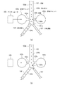
更に、特許文献6には、アクチュエータを使用して、微小粒子を所定の分岐流路に導く技術が開示されている。図17(a)及び(b)は特許文献6に記載の微小流体システムの動作を、その工程順に示す模式図である。図17(a)及び(b)に示すように、特許文献6に記載の微小流体システムでは、流路101に隣接して1対の密封チャンバ102a,102bが設けられている。この密封チャンバ102a,102bは、分岐点101aの直前において、側路103a,103bを介して流路101に連通している。また、側路103a,103bには、流路101を通流する液の一部が流入し、メニスカスが形成されている。
Furthermore, Patent Document 6 discloses a technique for guiding microparticles to a predetermined branch channel using an actuator. FIGS. 17A and 17B are schematic diagrams showing the operation of the microfluidic system described in Patent Document 6 in the order of the steps. As shown in FIGS. 17A and 17B, in the microfluidic system described in Patent Document 6 , a pair of sealed
この微小流体システムにより微小粒子104aを分取する場合、図17(a)に示すように、微小粒子104aが側路103a,103bの位置に到達するタイミングに合わせて、アクチュエータ105によって密封チャンバ102aを押圧する。これにより、側路103a内の液が流路101に押し出され、微小粒子104aの通流位置が側路103bの方向に偏向すると共に、側路103bのメニスカスが密封チャンバ102b方向に移動する。
When the
そして、図17(b)に示すように、微小粒子104aが側路103a,103bの位置を通過した後、アクチュエータ105による押圧を解除し、各側路103a,103bにおけるメニスカスの位置を元に戻す。これにより、回収対象外の微小粒子104bは、流路101の中央部を通流して分岐流路106に流入するようになり、回収対象の微小粒子104aのみ分岐流路107に流入させることができる。
Then, as shown in FIG. 17B, after the
しかしながら、前述した従来の技術には、以下に示す問題点がある。即ち、特許文献1に記載の分析分取装置では、微小粒子を液体の流れる方向とは異なる向きに移動させるため、微小粒子に対して大きな作用力を付与しなければならない。このため、回収対象の微小粒子がダメージを受けやすく、特に、微小粒子が細胞などの生体材料である場合は、回収対象の細胞などが死んでしまうという問題点がある。 However, the conventional techniques described above have the following problems. In other words, in the analytical sorting apparatus described in Patent Document 1, since the microparticles are moved in a direction different from the direction in which the liquid flows, a large acting force must be applied to the microparticles. For this reason, there is a problem in that the microparticles to be collected are easily damaged, and particularly when the microparticles are biomaterials such as cells, the cells to be collected die.
この点に関して、特許文献2,3に記載の技術は、細胞に電気的刺激を与えずに回収することが可能であるが、液体の駆動力にも電気浸透流ポンプを使用しており、更に、シース流も形成していないため、高速かつ高精度な検出を行うことができないという問題点がある。仮に、特許文献2,3に記載されているマイクロチップで、シース流を形成したとしても、後述する特許文献6と同様に、細胞が流路の分岐部分に衝突してダメージを受けたり、回収液中の細胞濃度が低く濃縮作業が必要になったりするといった問題が生じる。 In this regard, the techniques described in Patent Documents 2 and 3 can be collected without applying electrical stimulation to the cells, but also use an electroosmotic flow pump for the driving force of the liquid. Since the sheath flow is not formed, there is a problem that high-speed and high-precision detection cannot be performed. Even if the sheath flow is formed with the microchip described in Patent Documents 2 and 3, cells collide with the branch portion of the flow path and are damaged or collected, as in Patent Document 6 described later. There is a problem that the concentration of cells in the liquid is low and concentration work is required.
また、光ピンセットを使用する方法も微小粒子に対するダメージは少ないが、光ピンセットは高速で移動している微小粒子を補足することができないという問題点がある。このため、特許文献4,5に記載の方法は、送液を停止しなければ、目的の微小粒子を分取することができず、作業性に劣る。更に、特許文献4,5に記載されているような光ピンセットを使用する方法は、レーザ光の照射及び走査のための光学系が必要となるため、装置が複雑かつ大型になるという問題点もある。 In addition, the method using optical tweezers also causes little damage to microparticles, but optical tweezers have a problem that they cannot capture microparticles moving at high speed. For this reason, the methods described in Patent Documents 4 and 5 are inferior in workability because the desired fine particles cannot be collected unless the liquid feeding is stopped. Furthermore, the method using optical tweezers as described in Patent Documents 4 and 5 requires an optical system for laser beam irradiation and scanning, which causes a problem that the apparatus becomes complicated and large. is there.
一方、特許文献6に記載の方法は、制御流により微小粒子に流体力を作用させ、回収流路に流れ込む流線上に変位させることにより、回収対象の微小粒子を回収流路に導いているため、回収液中の微小粒子濃度が低く、濃縮などの作業が必要となるという問題点がある。通常、シース流を形成する際は、サンプル液の流量に対して大量のシース液流量を流し、検出部におけるサンプル流断面積を小さく絞ることにより、粒子位置ばらつきが小さいシース流を形成して、精度の良い検出を行う。 On the other hand, the method described in Patent Document 6 guides the microparticles to be collected to the recovery flow path by applying a fluid force to the microparticles by a controlled flow and displacing the microparticles on a streamline flowing into the recovery flow path. There is a problem in that the concentration of fine particles in the recovered liquid is low and work such as concentration is required. Normally, when forming a sheath flow, a large amount of sheath liquid flow rate is flowed with respect to the flow rate of the sample liquid, and by reducing the cross-sectional area of the sample flow in the detection unit, a sheath flow with small particle position variation is formed, Perform accurate detection.
そこで、サンプル液の流量とシース液の流量の比は、検出部で放物的な流速分布を持つ層流と仮定すれば見積もることができる。例えば、各辺200μmの正方形流路断面の検出部において、直径10μm程度のサンプル流断面を得ようとした場合、(シース液流量):(サンプル液流量)は、およそ250:1となる。ここで、特許文献6に記載の発明の様な構成の流路チップを用いた粒子取得装置では、動作中は絶えずシース液及びサンプル液が流れており、分岐後は各流路抵抗の逆比に分配され、各分岐流路を経てそれぞれの排出口から排出される。 Therefore, the ratio between the flow rate of the sample liquid and the flow rate of the sheath liquid can be estimated by assuming a laminar flow having a parabolic flow velocity distribution in the detection unit. For example, when a sample flow section having a diameter of about 10 μm is to be obtained in a detection section having a square channel cross section of 200 μm on each side, (sheath liquid flow rate) :( sample liquid flow rate) is approximately 250: 1. Here, in the particle acquisition apparatus using the channel chip having the configuration as in the invention described in Patent Document 6, the sheath liquid and the sample liquid constantly flow during operation, and after branching, the inverse ratio of each channel resistance. And is discharged from each outlet through each branch channel.
これを、前述した例(□200μmの検出流路、10μmのサンプル流断面)に適用し、1mlのサンプル液中の粒子の検出及び取得をする場合、約250mlのシース液を使うこととなる。更に、分岐後の回収用流路と廃棄用流路の流路抵抗が、例えば3:2であるとすると、これらの流量比は2:3となり、回収用流路側からは約100mlのシース液が排出されることとなる。即ち、全てのサンプル液1mlが回収用流路から取得されたとしても、回収液では約100倍に希釈されていることとなる。 When this is applied to the above-described example (□ 200 μm detection flow path, 10 μm sample flow cross section) to detect and acquire particles in 1 ml of sample liquid, about 250 ml of sheath liquid is used. Further, if the flow resistance of the recovery flow path and the waste flow path after branching is 3: 2, for example, the flow rate ratio is 2: 3, and about 100 ml of sheath liquid is provided from the recovery flow path side. Will be discharged. That is, even if all 1 ml of the sample liquid is acquired from the recovery channel, the recovered liquid is diluted about 100 times.
そして、回収対象の粒子が生細胞の場合、この生細胞を利用する際に濃縮などの操作が必要となるが、これは作業が面倒なだけでなく、細胞へのダメージも問題となる。これは、特に、回収した微小粒子が、全粒子数中ほんのわずかしか無いような場合に重大な問題となる。例えば、アダルトマウスの骨髄細胞から造血幹細胞を取得する場合、造血幹細胞は骨髄細胞104〜105個に1個程度の割合でしか含まれておらず、また、サンプル液は安定に送液するための制約などから、通常、1ml中に105〜107個程度の細胞濃度で準備される。そうすると、回収液中の細胞濃度は100ml中に1〜1000個程度に希釈されることとなり、濃縮自体が困難となる。 When the particles to be collected are living cells, an operation such as concentration is required when using the living cells. This is not only troublesome but also causes damage to the cells. This is a serious problem especially when the recovered microparticles are only a fraction of the total number of particles. For example, when obtaining hematopoietic stem cells from bone marrow cells of an adult mouse, the hematopoietic stem cells are contained only in a ratio of about 1 in 10 4 to 10 5 bone marrow cells, and the sample solution is sent stably. In general, the cell concentration is about 10 5 to 10 7 per ml. If it does so, the cell concentration in a collection | recovery liquid will be diluted to about 1-1000 pieces in 100 ml, and concentration itself will become difficult.
加えて、特許文献6に記載の方法は、流路の分岐点において、微小粒子が流路の壁面近傍を通過するため、回収対象の微小粒子が高速で壁面に衝突する可能性が高いという問題点がある。特に、微小粒子が生細胞である場合は、ダメージを受けやすく、壁面に衝突すると回収対象の細胞が死んでしまう虞もある。このように、細胞などの生体材料をダメージなく回収したい場合には、特許文献6に記載の方法は不向きである。 In addition, the method described in Patent Document 6 has a problem that the microparticles to be collected are likely to collide with the wall surface at high speed because the microparticles pass near the wall surface of the channel at the branch point of the channel. There is a point. In particular, when the microparticles are living cells, they are easily damaged, and there is a risk that the cells to be collected will die if they collide with the wall surface. Thus, when it is desired to collect biomaterials such as cells without damage, the method described in Patent Document 6 is not suitable.
そこで、本発明は、回収対象の微小粒子にダメージを与えることなく、高速でかつ安定して微小粒子を分取することができるマイクロチップ及び微小粒子分取装置を提供することを主目的とする。 Therefore, the main object of the present invention is to provide a microchip and a microparticle sorting apparatus that can sort microparticles at high speed and stably without damaging the microparticles to be collected. .
本発明に係るマイクロチップは、微小粒子を含むサンプル液が通流するサンプル液導入流路と、該サンプル液導入流路にその両側から合流し、前記サンプル液の周囲にシース液を導入する少なくとも1対のシース液導入流路と、前記サンプル液導入流路及びシース液導入流路に連通し、これらの流路を通流する液体が合流して通流する合流流路と、該合流流路に連通し、回収対象の微小粒子を吸引して引き込む負圧吸引部と、該負圧吸引部の両側に設けられ、前記合流流路に連通する少なくとも1対の廃棄用流路と、を有するものである。
このマイクロチップは、前記負圧吸引部が、前記合流流路と同軸状に設けられた吸引流路と、該吸引流路の途中に設けられた圧力室と、微小粒子回収時にのみ動作し、該圧力室の体積を一定量増加させるアクチュエータとを備えていてもよい。
その場合、前記アクチュエータとしては、例えばピエゾ素子を使用することができる。
又は、前記負圧吸引部が、前記合流流路と同軸状に設けられた吸引流路と、該吸引流路の途中に設けられた圧力室と、前記圧力室内に形成された電気浸透ポンプとを備えていてもよい。
また、前記吸引流路の流路幅は、前記合流流路よりも狭く、サンプル流よりも広くてもよい。
その場合、前記吸引流路の通流方向における断面の幅を前記合流流路の断面の幅よりも小さく、前記吸引流路の通流方向における断面の深さを前記合流流路の断面の深さよりも小さく、及び、前記吸引流路の通流方向における断面を前記サンプル流の通流方向における断面よりも大きくすることもできる。
更に、2枚の基板を貼り合わせることにより形成することができ、その場合、少なくとも、前記サンプル液導入流路、前記合流流路の一部、前記吸引流路及び前記圧力室は、一方の基板に形成されていることが望ましい。
The microchip according to the present invention includes at least a sample solution introduction channel through which a sample solution containing microparticles flows, and a sample solution introduction channel that joins the sample solution introduction channel from both sides and introduces a sheath solution around the sample solution. A pair of sheath liquid introduction flow paths, a merge flow path that communicates with the sample liquid introduction flow path and the sheath liquid introduction flow path, and a liquid that flows through these flow paths merges; A negative pressure suction part that communicates with the channel and sucks and pulls in the microparticles to be collected; and at least one pair of waste flow paths that are provided on both sides of the negative pressure suction part and communicate with the merging flow path. It is what you have.
In this microchip, the negative pressure suction part operates only when collecting fine particles, a suction channel provided coaxially with the merge channel, a pressure chamber provided in the middle of the suction channel, An actuator that increases the volume of the pressure chamber by a certain amount may be provided.
In that case, for example, a piezo element can be used as the actuator.
Alternatively, the negative pressure suction part includes a suction channel provided coaxially with the merge channel, a pressure chamber provided in the middle of the suction channel, and an electroosmotic pump formed in the pressure chamber. May be provided.
Further, the channel width of the suction channel may be narrower than the merge channel and wider than the sample stream.
In that case, the width of the cross section in the flow direction of the suction channel is smaller than the width of the cross section of the merge channel , and the depth of the cross section in the flow direction of the suction channel is the depth of the cross section of the merge channel. And the cross section in the flow direction of the suction flow path can be larger than the cross section in the flow direction of the sample flow.
Further, it can be formed by bonding two substrates. In that case, at least the sample liquid introduction channel, a part of the merging channel, the suction channel, and the pressure chamber are one substrate. It is desirable that it is formed.
本発明に係る微小粒子分取装置は、前述したマイクロチップが搭載されたものである。
この分取装置は、例えば、前記合流流路内を通流する微小粒子に光を照射する光照射部と、前記微小粒子から発せられた散乱光及び/又は蛍光を検出する検出部と、前記検出部で検出されたデータに基づいて、前記マイクロチップの負圧吸引部を制御する制御部と、を備えていてもよい。
また、負圧吸引部の駆動源がピエゾ素子である場合は、前記制御部は、ステップ状の信号により前記負圧吸引部の駆動を制御すればよい。
又は、負圧吸引部の駆動源が電気浸透ポンプである場合は、前記制御部は、矩形パルス状の信号により負圧吸引部の駆動を制御すればよい。
更に、前記微小粒子を、前記検出部で検出された順に分取し、その順番を保持した状態で負圧吸引部内に一列に貯留することもできる。
更にまた、検出部で検出されたデータに基づいて、負圧吸引部に微小粒子を引き込む工程と、前記負圧吸引部に引き込まれた微小粒子をマイクロチップから取り出す工程と、を前記制御部によってシーケンス制御してもよい。
The fine particle sorting apparatus according to the present invention is equipped with the above-described microchip.
The sorting apparatus includes, for example, a light irradiation unit that irradiates light to the microparticles flowing through the confluence channel, a detection unit that detects scattered light and / or fluorescence emitted from the microparticles, and the And a control unit that controls the negative pressure suction unit of the microchip based on data detected by the detection unit.
Further, when the driving source of the negative pressure suction unit is a piezo element, the control unit may control the driving of the negative pressure suction unit by a step-like signal.
Or when the drive source of a negative pressure suction part is an electroosmotic pump, the said control part should just control the drive of a negative pressure suction part with a rectangular pulse-shaped signal.
Furthermore, the fine particles can be collected in the order detected by the detection unit, and stored in a row in the negative pressure suction unit while maintaining the order.
Furthermore, based on the data detected by the detection unit, the step of drawing the microparticles into the negative pressure suction unit and the step of taking out the microparticles drawn into the negative pressure suction unit from the microchip are performed by the control unit. Sequence control may be performed.
本発明によれば、回収対象の微小粒子のみ吸引して回収しているため、微小粒子にダメージを与えることなく、シース液による希釈を最小限に抑え、高速でかつ安定して微小粒子を分取することができる。 According to the present invention, since only the fine particles to be collected are sucked and collected, the dilution with the sheath liquid is minimized without damaging the fine particles, and the fine particles are stably separated at high speed. Can be taken.
以下、本発明を実施するための形態について、添付の図面を参照して詳細に説明する。なお、本発明は、以下に示す各実施形態に限定されるものではない。また、説明は、以下の順序で行う。
1.第1の実施の形態
(負圧吸引部を備えるマイクロチップの例)
2.第1の実施の形態の変形例
(検出流路と負圧吸引部の吸引流路の深さが同じであるマイクロチップの例)
3.第2の実施の形態
(負圧吸引部に分別用分岐流路が設けられているマイクロチップの例)
4.第3の実施の形態
(第1の実施の形態のマイクロチップを使用した微小粒子分取装置の例)
5.第4の実施の形態
(アクチュエータとして電気浸透流ポンプを使用したマイクロチップの例)
DESCRIPTION OF EMBODIMENTS Hereinafter, embodiments for carrying out the present invention will be described in detail with reference to the accompanying drawings. In addition, this invention is not limited to each embodiment shown below. The description will be given in the following order.
1. First Embodiment (Example of a microchip having a negative pressure suction part)
2. Modified example of the first embodiment (an example of a microchip in which the detection flow channel and the suction flow channel of the negative pressure suction unit have the same depth)
3. Second Embodiment (Example of microchip in which a branching flow path for separation is provided in a negative pressure suction part)
4). Third Embodiment (Example of a microparticle sorting apparatus using the microchip of the first embodiment)
5). Fourth Embodiment (Example of microchip using an electroosmotic flow pump as an actuator)
<1.第1の実施の形態>
[マイクロチップの全体構成]
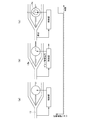
先ず、本発明の第1の実施形態に係るマイクロチップについて説明する。図1は本実施形態のマイクロチップの構成を模式的に示す図であり、図2はそのA−A線による断面図である。図1,2に示すように、本実施形態のマイクロチップ1には、微小粒子を含むサンプル液2が導入されるサンプル液導入流路11と、シース液3が導入される1対のシース液導入流路12a,12bが設けられている。
<1. First Embodiment>
[Overall configuration of microchip]
First, the microchip according to the first embodiment of the present invention will be described. FIG. 1 is a diagram schematically showing the configuration of the microchip of this embodiment, and FIG. 2 is a cross-sectional view taken along the line AA. As shown in FIGS. 1 and 2, in the microchip 1 of this embodiment, a sample
シース液導入流路12a,12bは、サンプル液導入流路11に両側から合流し、その合流点よりも下流側には1本の合流流路13が設けられている。そして、合流流路13内においては、サンプル流2aの周囲をシース流3aで囲み、層流を形成した状態で液が通流するようになっている。これにより、サンプル液2中の微小粒子は、その通流方向に対して略1列に並んで通流することとなる。
Sea scan
一方、合流流路13の下流側端部には、回収対象の微小粒子を分取するための負圧吸引部14と、回収対象外の微小粒子などを排出するための廃棄用流路15a,15bが設けられており、これらはいずれも合流流路13に連通している。なお、廃棄用流路15a,15bの下流側端部は、例えば、廃液タンクなどに連結される。このマイクロチップ1では、合流流路13において個々の微小粒子を検出し、その結果、回収対象であると判断された微小粒子のみが負圧吸引部14内に引き込まれ、それ以外の微小粒子は廃棄用流路15a,15bから排出される。
On the other hand, at the downstream end of the merging
[負圧吸引部14]
負圧吸引部14は、所定のタイミングで回収対象の微小粒子を吸引することができれば、その構成は特に限定されるものではないが、例えば、図1に示すように、合流流路13に連通する吸引流路14aと、この吸引流路14aの一部に形成された圧力室14bと、圧力室14b内の体積を任意のタイミングで拡張可能なアクチュエータ14cとで構成することができる。なお、吸引流路14aの下流側端部は、バルブ(図示せず)などにより開閉可能となっていることが望ましい。
[Negative pressure suction part 14]
The configuration of the negative
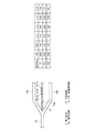
図3(a)及び(b)は図1に示すマイクロチップ1における負圧吸引部14と廃棄用流路15a,15bの分岐部分を示す斜視図であり、図3(c)はその断面図である。図3(a),(b)に示すように、吸引流路14aは、合流流路13と同軸状に形成されており、その通流方向における断面が、合流流路13の断面よりも幅及び深さ共に小さく、かつサンプル流2aの断面よりも大きくなっている。これにより、シース液3による回収液の希釈を抑制しつつ、回収対象の微小粒子をダメージなく回収することが可能となる。
3 (a) and 3 (b) are perspective views showing a branched portion of the negative
また、圧力室14bは、振動板14dを介して、ピエゾ素子などのアクチュエータ14cと連結されている。そして、このアクチュエータ14cを動作させると、振動板14dがアクチュエータ14c側に引きよせられ、圧力室14b内の体積が増加するようになっている。ここで、振動板14dは、アクチュエータ14cが固定されている部分が厚く、アクチュエータ14cが接触していない部分の厚さの方が薄くなっていることが望ましい。これにより、厚さの薄い撓み振動板部分が弱い力で変形し、高速に駆動することが可能となる。
The
本実施形態のマイクロチップ1は、例えば、図2に示すように、前述した各流路及び負圧吸引部などが形成された2枚の基板を貼り合わせることにより製造することができる。図4は他のマイクロチップ構成例を示す断面図であり、図1に示すA−A線による断面図に相当する。このマイクロチップ1は、図4に示すように、各流路などが2枚の基板の両方に形成されている構成とすることもできるが、図2に示すように、少なくとも、サンプル液導入流路11、合流流路13の検出領域13a、吸引流路14a及び圧力室14bが、一方の基板にのみ形成されている構成とすることが望ましい。このように、流路径が細い部分を一方の基板にのみ形成する構成とすることで、貼り合わせ時の位置調整が容易になる。
For example, as shown in FIG. 2, the microchip 1 of the present embodiment can be manufactured by bonding two substrates on which the above-described channels and negative pressure suction parts are formed. FIG. 4 is a cross-sectional view showing another microchip configuration example, and corresponds to a cross-sectional view taken along line AA shown in FIG. As shown in FIG. 4, the microchip 1 may be configured such that each flow path is formed on both of the two substrates. However, as shown in FIG. It is desirable that the
また、マイクロチップ1を形成する材料としては、例えば、ポリカーボネート、シクロオレフィンポリマー、ポリプロピレン、PDMS(polydimethylsiloxane)、ガラス及びシリコン等が挙げられる。特に、加工性に優れ、成形装置を使用して安価に複製することができることから、ポリカーボネート、シクロオレフィンポリマー、ポリプロピレン等の高分子材料で形成することが好ましい。このように、プラスチック成形基板を貼り合わせる構成とすることにより、マイクロチップ1を安価に製造することが可能となる。 Examples of the material for forming the microchip 1 include polycarbonate, cycloolefin polymer, polypropylene, PDMS (polydimethylsiloxane), glass, and silicon. In particular, since it is excellent in processability and can be inexpensively replicated using a molding apparatus, it is preferably formed of a polymer material such as polycarbonate, cycloolefin polymer, or polypropylene. Thus, it becomes possible to manufacture the microchip 1 at low cost by adopting a configuration in which the plastic molded substrates are bonded together.
本実施形態のマイクロチップ1では、液滴荷電方式などのように液滴生成を行わないため、物理的に安定した系で、目的の微小粒子を回収することが可能である。また、チップ内で検出及び分取を行うことが可能であるため、ミストが飛散する心配がなく、バイオハザードの観点からも、安全に回収作業を行うことができる。更に、本実施形態のマイクロチップ1は、安価に製造することが可能であるため、使い捨てチップとして使うことができ、細胞のコンタミネーションが問題となる再生医療等にも応用することが可能である。 Since the microchip 1 of the present embodiment does not generate droplets unlike the droplet charging method, it is possible to collect target microparticles in a physically stable system. Further, since detection and sorting can be performed in the chip, there is no fear of mist scattering, and the recovery operation can be performed safely from the viewpoint of biohazard. Furthermore, since the microchip 1 of the present embodiment can be manufactured at a low cost, it can be used as a disposable chip, and can be applied to regenerative medicine and the like in which cell contamination is a problem. .
そして、本実施形態のマイクロチップ1は、チップ交換した場合も、液滴荷電方式のような吐出ノズルの位置調整、液滴の着弾位置と回収カラムの位置調整など面倒な調整を行う必要がなく、簡便に使用することができる。また、本実施形態のマイクロチップ1では、回収対象の微小粒子を1個ずつ、吸引流路14aに負圧吸引するため、微小粒子と共に吸引流路14aに引き込まれる液の量を必要最低限にすることができる。これにより、シース液による希釈を、液滴荷電方式と同等に抑えることができる。
And even if the microchip 1 of this embodiment is replaced, there is no need to perform troublesome adjustments such as the position adjustment of the discharge nozzle and the position adjustment of the droplet landing position and the recovery column as in the droplet charging method. Can be used conveniently. Further, in the microchip 1 of the present embodiment, since the microparticles to be collected are sucked into the
更に、本実施形態のマイクロチップ1では、吸引流路14aが、合流流路13と同軸状、即ちサンプル流2aが通流する位置に設けられているため、回収対象の微小粒子は、流路の壁面に触れることなく、吸引流路14a内に引き込まれる。これにより、微小粒子の受けるダメージを、最低限に抑えることができる。
Furthermore, in the microchip 1 of the present embodiment, the
更にまた、本実施形態のマイクロチップ1においては、吸引流路14aに引き込まれた微小粒子は、分取された順に、一列に貯留されるため、例えば、システムに保存された検出データと一対一に対応付けることも可能である。そして、吸引流路14aから微小粒子を回収する際に、その順序を崩さずに、チップ外に取り出すことも可能である。なお、液滴荷電方式で、検出データと一対一対応の粒子取得を行おうとすると、微小粒子毎に回収カラムなどを用意する必要となるため、現実的ではない。
Furthermore, in the microchip 1 of the present embodiment, the microparticles drawn into the
<2.第1の実施の形態の変形例>
前述した第1の実施形態においては、吸引流路14aの通流方向における断面を、合流流路13の断面よりも幅及び深さ共に小さくしているが、本発明はこれに限定されるものではなく、合流流路13と同じ深さにしてもよい。図5(a)は本発明の第1の実施形態の変形例に係るマイクロチップにおける負圧吸引部と廃棄用流路の分岐部分を示す斜視図であり、図5(b)は分岐部分における微小粒子の軌道を示す図である。
<2. Modification of First Embodiment>
In the first embodiment described above, the cross section in the flow direction of the
図5(a)に示すように、本変形例のマイクロチップ10でも、吸引流路14aは、合流流路13と同軸状に形成されているが、その通流方向における断面は、合流流路13の断面に比べて、幅のみが細くなっており、深さは同じになっている。このように、吸引流路14aの深さを合流流路13と同じにした場合も、吸引流路14aはサンプル流2aが通流する位置に設けられているため、ダメージを与えることなく、回収対象の微小粒子を負圧吸引することができる。
As shown in FIG. 5 (a), in the microchip 10 of this modification, the
また、本変形例のマイクロチップ10のような構成にすると、回収対象の微小粒子が想定よりも大きかった場合でも、詰まりを発生させることなく、回収流路14aに引き込むことが可能となる。ただし、図5(b)に示すように、僅かではあるが、微小粒子が吸引流路14a内に入り込み、深さ方向に回流した後、廃棄用流路15a,15bに流れるようになるため、分岐部分における微小粒子の滞留時間が長くなることがある。
Further, with the configuration of the microchip 10 of the present modification, even when the microparticles to be collected are larger than expected, they can be drawn into the
<3.第2の実施の形態>
次に、本発明の第2の実施形態に係るマイクロチップについて説明する。図6は本実施形態のマイクロチップの構成を模式的に示す図である。なお、図6においては、図1に示すマイクロチップ1の構成要素と同じものには、同じ符号を付し、その詳細な説明は省略する。図6に示すように、本実施形態のマイクロチップ20では、負圧吸引部24に、微小粒子回収用の分岐流路14eが設けられている以外は、前述した第1の実施形態と同様である。
<3. Second Embodiment>
Next, a microchip according to a second embodiment of the present invention will be described. FIG. 6 is a diagram schematically showing the configuration of the microchip of this embodiment. In FIG. 6, the same components as those of the microchip 1 shown in FIG. 1 are denoted by the same reference numerals, and detailed description thereof is omitted. As shown in FIG. 6, the
[分岐流路14e]
分岐流路14eは、吸引流路14aに負圧吸引された微小粒子を、圧力室14bを経由せずに回収するためのものであり、その下流側端部は、バルブ(図示せず)を介してアクチュエータ(図示せず)に連結されている。そして、微小粒子を回収する際は、圧力室14bに連結されたバルブを閉じた状態で、微小粒子回収用の分岐流路14eに連結されたバルブを開き、アクチュエータを動作させる。これにより、圧力室14bを経由せずに、チップから微小粒子を取り出すことができるため、微小粒子を分取した順に1列に並べた状態で、取り出すことが可能となる。
[
The
<4.第3の実施の形態>
[装置構成]
次に、本発明の第3の実施形態に係る微小粒子分取装置(以下、単に「分取装置」ともいう。)について説明する。図7は本実施形態の微小粒子分取装置の構成を模式的に示す図である。図7に示すように、本実施形態の分取装置は、例えば前述した第1の実施形態のマイクロチップ1を使用して、複数の微小粒子を含む液から、特定の微小粒子を回収する装置である。
<4. Third Embodiment>
[Device configuration]
Next, a microparticle sorting apparatus (hereinafter, also simply referred to as “sorting apparatus”) according to a third embodiment of the present invention will be described. FIG. 7 is a diagram schematically showing the configuration of the microparticle sorting apparatus of the present embodiment. As shown in FIG. 7, the sorting apparatus of the present embodiment uses, for example, the microchip 1 of the first embodiment described above to collect specific microparticles from a liquid containing a plurality of microparticles. It is.
具体的には、本実施形態の分取装置30は、例えば、マイクロチップ1の合流流路13を通流する微小粒子に励起光を照射する光照射部31と、励起光が照射された微小粒子から発せられた光を検出する光検出部32と、光検出部32での検出結果に基づいてマイクロチップ1の負圧吸引部14を制御する制御部33を備えている。
Specifically, the sorting device 30 of the present embodiment includes, for example, a
[微小粒子の分取方法]
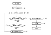
次に、本実施形態の微小粒子分取装置30を使用して、微小粒子を分取する方法について説明する。図8は本実施形態の微小粒子分取方法を示すフローチャート図である。本実施形態の分取装置30で、微小粒子を分取する場合は、先ず、マイクロチップ1を装置に装着する。その後、図8に示すように、シース液導入流路12a,12bにシース液3を導入し、合流流路13、負圧吸引部14(吸引流路14a,圧力室14b)及び廃棄用流路15a,15bをシース液3で満たす(ステップS1)。
[Small particle sorting method]
Next, a method for sorting microparticles using the microparticle sorting apparatus 30 of the present embodiment will be described. FIG. 8 is a flowchart showing the fine particle sorting method of the present embodiment. In order to sort out microparticles with the sorting apparatus 30 of this embodiment, first, the microchip 1 is mounted on the apparatus. Thereafter, as shown in FIG. 8, the sheath liquid 3 is introduced into the sheath liquid
次に、吸引流路14aの下流側端部をバルブで閉じ、シース液3と共にサンプル液2を導入して、層流を形成し、微小粒子の検出及び回収を行う(ステップS2)。図9(a)〜(f)は、図8に示す微小粒子回収時の動作を、その工程順に示す図である。ステップS2においては、先ず、合流流路13を通流するサンプル流2a中の微小粒子に、例えば波長488nmのレーザ光などの励起光を照射する。そして、この微小粒子から発せられる散乱光(前方散乱光,後方散乱光)及び/又は蛍光を、光検出部32に設けられた検出器(フォトディテクターやフォトマルチプライヤなど)で信号検出する。
Next, the downstream end of the
次に、検出された信号を、必要に応じてプリアンプして、制御部33に送る。そして、制御部33において、検出信号に基づき、その微小粒子が回収対象か否かを判断する。もし、検出した微小粒子が回収対象である場合は、図9(a)〜(f)に示すように、その微小粒子が励起光を照射された位置から分岐部まで移動する時間(遅れ時間)を経過した後に、ピエゾ駆動信号などのアクチュエータ14cを駆動するための信号を発生する。その際、必要であれば、アンプを介してアクチュエータ14cを駆動させるようにしてもよい。
Next, the detected signal is preamplified as necessary and sent to the
例えば、アクチュエータ14cがピエゾ素子である場合は、ピエゾ印加電圧を制御するとピエゾ変形力が発生し、これにより圧力室14b内の体積が変化するため、負圧吸引部14の内圧を制御することができる。具体的には、ピエゾ収縮となる電圧を印加し、圧力室14b内の体積を増加させ、その内圧を負圧にすることで、吸引流路14aに微小粒子を引き込む。その際の吸引量は、印加電圧を変えることにより制御することができる。
For example, when the
一方、アクチュエータ14cとしてピエゾ素子を使用する場合、ピエゾ素子の変位、即ち駆動電圧が、圧力室14bの体積に直結する。このため、駆動波形を反転矩形パルス波形とすると、矩形波の立ち下がり時に吸引流路14aに引き込んだ微小粒子を、矩形波の立ち上がり時に吐出してしまう可能性がある。よって、ピエゾ素子の場合は、吸引流路14aに連続して微小粒子を引き込み、溜めていくためには、入力信号の波形をステップ状にする必要がある。
On the other hand, when a piezo element is used as the
このように、本実施形態の微小粒子分取方法によれば、回収対象の微小粒子のみを、安定して吸引することが可能となる。また、最低限の量を繰り返し吸引することで、吸引流路14a内が希釈されることを防止することができると共に、検出した順に微小粒子を並べて貯めていくことができる。一方、回収対象外の微小粒子が検出されたときは、アクチュエータ14cを駆動させなければよい。これにより、回収対象外の微小粒子は、廃棄用流路15a,15bに流れ、外部に排出されることとなる。
Thus, according to the fine particle sorting method of the present embodiment, it is possible to stably suck only the fine particles to be collected. Further, by repeatedly sucking the minimum amount, it is possible to prevent the inside of the
そして、サンプル液2の全量を導入し終えた場合、又は、回収した微小粒子の数がマイクロチップ1の回収可能量に達した場合は、マイクロチップ1から微小粒子を取り出す(ステップS3)。ここで、「マイクロチップ1の回収可能量に達した場合」とは、吸引流路が微小粒子で一杯になったとき、又は、ピエゾ素子などのアクチュエータ14cの可動範囲が限界に達したときなどである。 Then, when the introduction of the entire amount of the sample liquid 2 is completed, or when the number of collected microparticles reaches the recoverable amount of the microchip 1, the microparticles are taken out from the microchip 1 (step S3). Here, “when the recoverable amount of the microchip 1 has been reached” means when the suction flow path is filled with fine particles, or when the movable range of the actuator 14c such as a piezo element has reached its limit. It is.
図10(a)〜(c)は図8に示す微小粒子取り出し時の動作を、その工程順に示す図である。ステップS3では、先ず、図10(a)に示すように、シース液3を導入した状態で、サンプル液2の導入のみ中止し、合流流路13の下流側端部の分岐点よりも上流側には、サンプル液2(微小粒子)が存在しない状態にする。その後、図10(b)に示すように、吸引流路14aに接続されたバルブを開放する。これにより、シース液3の供給圧力により、吸引流路14a内に貯留されていた液が微小粒子と共に流出するため、回収対象の微小粒子をマイクロチップ1外に取り出すことができる。
FIGS. 10A to 10C are views showing the operation at the time of taking out the fine particles shown in FIG. 8 in the order of the steps. In step S3, first, as shown in FIG. 10A, in the state where the sheath liquid 3 is introduced, only the introduction of the sample liquid 2 is stopped, and the upstream side of the branch point at the downstream end of the
そして、図10(c)に示すように、回収した微小粒子を全て取りだした後、マイクロチップ1内のアクチュエータ14cを初期状態に戻す。なお、サンプル液2の全量について、検出・回収していない場合は、再度、吸引流路14aに接続されたバルブを閉め、サンプル液2を導入して、ステップS2の微小粒子の検出及び回収を行う。
Then, as shown in FIG. 10C, after all the collected fine particles are taken out, the
一方、サンプル液2の全量の検出・回収が完了した場合は、ステップS3で微小粒子を取りだした後、サンプル液導入流路11及びシース液導入流路12a,12bの両方に、シース液3又は洗浄液を導入し、流路内を洗浄する(ステップS4)。更に、必要に応じて、その後、純水などの保存液を導入し、流路内を保存液で置換してもよい。 On the other hand, when the detection and recovery of the entire amount of the sample liquid 2 is completed, after the microparticles are taken out in step S3, the sheath liquid 3 or the sheath liquid 3 or A cleaning liquid is introduced to clean the inside of the flow path (step S4). Further, if necessary, after that, a storage solution such as pure water may be introduced to replace the inside of the flow path with the storage solution.
本実施形態の微小粒子分取装置では、液滴を形成しないため、物理的に安定した系で、目的の微小粒子を回収することが可能である。また、マイクロチップ内で検出及び分取を行っているため、ミストが飛散する心配がなく、安全に回収作業を行うことができる。更に、本実施形態の微小粒子分取装置は、チップ交換した場合も、液滴荷電方式のような吐出ノズルの位置調整、液滴の着弾位置と回収カラムの位置調整など煩雑な作業を行う必要がないため、作業の効率化を図れる。 In the microparticle sorting apparatus of the present embodiment, since droplets are not formed, it is possible to collect target microparticles with a physically stable system. Moreover, since the detection and sorting are performed in the microchip, there is no fear of mist scattering, and the recovery operation can be performed safely. Furthermore, the microparticle sorting apparatus of this embodiment needs to perform complicated operations such as the position adjustment of the discharge nozzle, the position of the droplet landing and the position of the recovery column, etc., even when the chip is replaced. Since there is no such thing, work efficiency can be improved.
本実施形態の微小粒子分取装置では、回収液中の微小粒子濃度が高いため、濃縮作業を最低限に抑えることができる。これにより、微小粒子のダメージも抑制することが可能となる。図11は微小粒子分取時の状態を模式的に示す図である。また、図11に示すように、本実施形態の微小粒子分取装置では、微小粒子4は、検出部32で検出された順に分取され、その順番を保持した状態で負圧吸引部14の吸引流路14a内に一列に貯留される。これにより、例えば、システムに保存された検出データと一対一に対応付けることが可能となる。そして、吸引流路から微小粒子を取り出す際も、その順序を崩さずに、チップ外に取り出すことも可能である。
In the fine particle sorting apparatus of the present embodiment, the concentration work can be minimized because the concentration of fine particles in the collected liquid is high. Thereby, it is possible to suppress damage to the fine particles. FIG. 11 is a diagram schematically showing a state at the time of fine particle sorting. In addition, as shown in FIG. 11, in the microparticle sorting apparatus of the present embodiment, the microparticles 4 are sorted in the order detected by the
加えて、本実施形態の微小粒子分取装置においては、回収した微小粒子を、その特性などに応じて、分別して回収することも可能である。図12は、吸引流路14a中の微小粒子と検出データを、検出データに基づいて回収する方法の例を模式的に示す図である。図12に示すように、マイクロチップ1の吸引流路14a内では、微小粒子は、検出された順に一列に並んで貯留されているため、検出データを一対一で対応させることができる。
In addition, in the microparticle sorting apparatus of the present embodiment, the collected microparticles can be separated and collected according to the characteristics thereof. FIG. 12 is a diagram schematically illustrating an example of a method of collecting the microparticles and the detection data in the
そして、例えば、シリンジポンプ34a〜34eなどの粒子回収アクチュエータなどを使用することにより、特定の微小粒子を選択して取り出すことができる。これにより、液滴荷電方式のような煩雑な操作をしなくても、複数種の微小粒子を一度に回収し、その後、容易に分別しながら取り出すことが可能となる。 For example, specific microparticles can be selected and taken out by using particle recovery actuators such as syringe pumps 34a to 34e. This makes it possible to collect a plurality of types of microparticles at a time without taking a complicated operation such as a droplet charging method, and then easily take out them while separating them.
一方、前述したように、「マイクロチップ1の回収可能量」はチップ設計によって決まり、また、吸引流路14aに引きこまれた微小粒子の数は、システムによりカウントすることができる。そこで、本実施形態の微小粒子分取装置では、「マイクロチップ1の回収可能量」を予め設定しておくことにより、ステップS2とステップS3の繰り返し動作、更には、ステップS1〜ステップS4の全ての動作について、制御部33によりシーケンス制御が可能となる。
On the other hand, as described above, the “recoverable amount of the microchip 1” is determined by the chip design, and the number of microparticles drawn into the
<5.第4の実施の形態>
次に、本発明の第4の実施形態に係るマイクロチップについて説明する。図13は本実施形態のマイクロチップの構成を模式的に示す図である。なお、図13においては、図1に示すマイクロチップ1及び図6に示すマイクロチップ20の構成要素と同じものには、同じ符号を付し、その詳細な説明は省略する。図13に示すように、本実施形態のマイクロチップ40では、負圧吸引部44に、圧力室の体積を一定量増加させるアクチュエータとして、電気浸透流ポンプが設けられている以外は、前述した第2の実施形態と同様である。
<5. Fourth Embodiment>
Next, a microchip according to a fourth embodiment of the present invention will be described. FIG. 13 is a diagram schematically showing the configuration of the microchip of this embodiment. In FIG. 13, the same components as those of the microchip 1 shown in FIG. 1 and the
[負圧吸引部44]
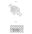
図14(a)及び(b)は図13に示すマイクロチップ40の負圧吸引部44に設けられた電気浸透ポンプの構成を示す断面図であり、図14(a)は厚さ方向に垂直な断面を、図14(b)は厚さ方向に平行な断面をそれぞれ示す。本実施形態のマイクロチップ40の負圧吸引部44には、吸引流路44aの一部に形成された圧力室44b内に電気浸透流ポンプが形成されている。具体的には、圧力室44b内の液体により電気二重層を形成するための1対の電極44c,44dが設けられている。即ち、電極44cと電極44dに挟まれる部分が電気二重層形成部44fとなる。
[Negative pressure suction part 44]
14A and 14B are cross-sectional views showing the configuration of the electroosmotic pump provided in the negative
図15(a)は電気二重層形成部44fの構成例を示す斜視図であり、図15(b)は断面図である。電気二重層形成部44fの構成は、特に限定されるものではなく、例えばシリカ多孔質体で形成したり、図15(a),(b)に示すようにピラーを高密度で配置し、流路をアレイ状にしたりすることもできる。また、固相を形成する材料も特に限定されるものではなく、チップと同様にガラス、シリコン又はアクリルなどで形成してもよく、更にSiO2スパッタなどにより表面処理することもできる。
FIG. 15A is a perspective view showing a configuration example of the electric double
電気二重層形成部44fを前述した多孔質体や微細流路構造とすることにより、高い駆動圧力を得ることができるが、その一方で、圧力室44b内に微小粒子を通流させることができなくなる。そこで、電気二重層形成部44fをこのような構成にするときは、別途、微小粒子回収用の分岐流路44eを設ける必要がある。
Although the electric double
図16(a)〜(c)は電極44c,44dの構成例を示す断面図である。また、電極44c,44dの構成も、特に限定されるものではなく、例えば図16(a)に示すように、金、白金又はアルミニウムなどからなる導電積板からなる電極44c,44dを、圧力室44b内に配置してからチップを貼り合わせ、接着剤44gで封止してもよい。
16A to 16C are cross-sectional views showing a configuration example of the
また、図16(b)に示すように、圧力室44bの表面に、金、白金又はアルミニウムなどの金属又はITO(酸化インジウムズズ)をスパッタリングした薄膜電極44c,44dを形成しておき、それにコンタクトピン44hを接続してもよい。更に、図16(c)に示すように、チップ成形時に電極44c,44dを封入し、一体成形することもできる。
Further, as shown in FIG. 16B,
そして、この電気二重層が形成されている状態で、流路方向に沿って電圧を印加することにより、圧力室内44bの液体が移動し、電気浸透ポンプとして機能する。その際の電圧印加方向は、例えばシリカ多孔質体などのように、固体表面が負に帯電している場合は、通流方向上流側の電極44cに正の電圧を印加して下流側の電極44dを接地するか、又は、電極44cを接地して電極44dに負の電圧を印加する。一方、固体表面が正に帯電している場合は、電極44cを接地して電極44dに正の電圧を印加するか、又は、電極44cに負の電圧を印加して電極44dを接地する。
In the state where the electric double layer is formed, by applying a voltage along the flow path direction, the liquid in the
この電気浸透ポンプは、駆動電圧を印加している場合にのみ作動し、負圧を発生するため、入力信号の波形は、矩形パルス状とする必要がある。これは、前述したピエゾ素子を使用した場合のように、入力信号の波形をステップ状にすると、吸引流路に引き込み続けることとなるからである。 Since this electroosmotic pump operates only when a driving voltage is applied and generates a negative pressure, the waveform of the input signal needs to be a rectangular pulse. This is because if the waveform of the input signal is stepped as in the case of using the above-described piezo element, it will continue to be drawn into the suction channel.
また、電気浸透流ポンプ(圧力室44b)の下流側に設けられるバルブは、少なくとも電気浸透流ポンプがONのときは、開放しておく必要がある。なお、電気二重層形成部を多孔質体で形成した場合、多孔質体は流体抵抗が大きいため、電気浸透ポンプがOFFのときにも吸引流路44aに流入する流量は少ないが、逆バイアスの電圧を印加することにより、吸引流路44aへの流入を更に抑制することができる。
Further, the valve provided on the downstream side of the electroosmotic flow pump (
本実施形態のマイクロチップでは、電気浸透流ポンプにより、微小粒子の吸引を行うため、ピエゾ素子を使用する場合のような最大変位量(最大印加電圧)による制限がなくなる。これにより、1回の操作で回収可能粒子数が多い分取用マイクロチップを実現することができる。また、電気浸透流ポンプは、無音及び無振動で動作するため、使用可能な場所の選択の幅が広がる。なお、本実施形態における上記以外の構成及び効果は、前述した第1の実施形態及び第2の実施形態と同様である。 In the microchip of this embodiment, fine particles are sucked by an electroosmotic flow pump, so that there is no limitation due to the maximum displacement (maximum applied voltage) as in the case of using a piezo element. Thereby, a microchip for sorting with a large number of particles that can be collected in one operation can be realized. In addition, since the electroosmotic flow pump operates with no sound and no vibration, the range of available locations is widened. The configuration and effects other than those described above in the present embodiment are the same as those in the first embodiment and the second embodiment described above.
1、10、20、40 マイクロチップ
2 サンプル液
2a サンプル流
3 シース液
3a シース流
4、104a、104b 微小粒子
11 サンプル液導入流路
12a、12b シース液導入流路
13 合流流路
13a 検出領域
14、24、44 負圧吸引部
14a、44a 吸引流路
14b、44b 圧力室
14c、105 アクチュエータ
14d 振動板
14e、44e 分岐流路
30 微小粒子分取装置
31 光照射部
32 検出部
33 制御部
34a〜34e シリンジポンプ
44c、44d 電極
44f 電気二重層形成部
44g 接着剤
44h コンタクトピン
101 流路
101a 分岐点
102a、102b 密封チャンバ
103a、103b 側路
DESCRIPTION OF
Claims (14)
該サンプル液導入流路にその両側から合流し、前記サンプル液の周囲にシース液を導入する少なくとも1対のシース液導入流路と、
前記サンプル液導入流路及びシース液導入流路に連通し、これらの流路を通流する液体が合流して通流する合流流路と、
該合流流路に連通し、回収対象の微小粒子を吸引して引き込む負圧吸引部と、
該負圧吸引部の両側に設けられ、前記合流流路に連通する少なくとも1対の廃棄用流路と、
を有するマイクロチップ。 A sample solution introduction channel through which a sample solution containing fine particles flows;
At least one pair of sheath liquid introduction flow paths that join the sample liquid introduction flow path from both sides and introduce sheath liquid around the sample liquid;
Communicating with the sample liquid introduction flow path and the sheath liquid introduction flow path, and a merge flow path through which the liquid flowing through these flow paths merges and flows;
A negative pressure suction part that communicates with the confluence channel and sucks and draws in the fine particles to be collected;
At least one pair of disposal channels provided on both sides of the negative pressure suction part and communicating with the merge channel;
Having a microchip.
前記合流流路と同軸状に設けられた吸引流路と、
該吸引流路の途中に設けられた圧力室と、
微小粒子回収時にのみ動作し、該圧力室の体積を一定量増加させるアクチュエータと、
を備える請求項1に記載のマイクロチップ。 The negative pressure suction part is
A suction channel provided coaxially with the merging channel;
A pressure chamber provided in the middle of the suction channel;
An actuator that operates only during microparticle recovery and increases the volume of the pressure chamber by a certain amount;
The microchip according to claim 1, comprising:
前記合流流路と同軸状に設けられた吸引流路と、
該吸引流路の途中に設けられた圧力室と、
前記圧力室内に形成された電気浸透ポンプと、
を備える請求項1に記載のマイクロチップ。 The negative pressure suction part is
A suction channel provided coaxially with the merging channel;
A pressure chamber provided in the middle of the suction channel;
An electroosmotic pump formed in the pressure chamber;
The microchip according to claim 1, comprising:
前記微小粒子から発せられた散乱光及び/又は蛍光を検出する検出部と、
前記検出部で検出されたデータに基づいて、前記マイクロチップの負圧吸引部を制御する制御部と、
を有する請求項9に記載の微小粒子分取装置。 A light irradiation unit for irradiating light to the microparticles flowing through the confluence channel;
A detection unit for detecting scattered light and / or fluorescence emitted from the microparticles;
A control unit for controlling the negative pressure suction unit of the microchip based on the data detected by the detection unit;
The fine particle sorting device according to claim 9, comprising:
前記制御部は、ステップ状の信号により前記負圧吸引部の駆動を制御する請求項10に記載の微小粒子分取装置。 The drive source of the negative pressure suction part is a piezo element,
The fine particle sorting device according to claim 10, wherein the control unit controls driving of the negative pressure suction unit by a step-like signal.
前記制御部は、矩形パルス状の信号により負圧吸引部の駆動を制御する請求項10に記載の微小粒子分取装置。 The drive source of the negative pressure suction part is an electroosmotic pump,
The fine particle sorting device according to claim 10, wherein the control unit controls driving of the negative pressure suction unit by a rectangular pulse signal.
前記負圧吸引部に引き込まれた微小粒子をマイクロチップから取り出す工程と、
を前記制御部によってシーケンス制御する請求項10乃至13のいずれか1項に記載の微小粒子分取装置。 Based on the data detected by the detection unit, drawing the microparticles into the negative pressure suction unit;
Removing microparticles drawn into the negative pressure suction part from the microchip;
The fine particle sorting device according to any one of claims 10 to 13, wherein the control unit performs sequence control.
Priority Applications (3)
| Application Number | Priority Date | Filing Date | Title |
|---|---|---|---|
| JP2010282167A JP5720233B2 (en) | 2010-12-17 | 2010-12-17 | Microchip and fine particle sorting device |
| US13/315,052 US8487273B2 (en) | 2010-12-17 | 2011-12-08 | Microchip and particulate fractional collection apparatus |
| CN201110409903.1A CN102564925B (en) | 2010-12-17 | 2011-12-09 | Microchip and microgranule dispensing package |
Applications Claiming Priority (1)
| Application Number | Priority Date | Filing Date | Title |
|---|---|---|---|
| JP2010282167A JP5720233B2 (en) | 2010-12-17 | 2010-12-17 | Microchip and fine particle sorting device |
Publications (3)
| Publication Number | Publication Date |
|---|---|
| JP2012127922A JP2012127922A (en) | 2012-07-05 |
| JP2012127922A5 JP2012127922A5 (en) | 2013-12-19 |
| JP5720233B2 true JP5720233B2 (en) | 2015-05-20 |
Family
ID=46233158
Family Applications (1)
| Application Number | Title | Priority Date | Filing Date |
|---|---|---|---|
| JP2010282167A Active JP5720233B2 (en) | 2010-12-17 | 2010-12-17 | Microchip and fine particle sorting device |
Country Status (2)
| Country | Link |
|---|---|
| US (1) | US8487273B2 (en) |
| JP (1) | JP5720233B2 (en) |
Families Citing this family (42)
| Publication number | Priority date | Publication date | Assignee | Title |
|---|---|---|---|---|
| US9943847B2 (en) | 2002-04-17 | 2018-04-17 | Cytonome/St, Llc | Microfluidic system including a bubble valve for regulating fluid flow through a microchannel |
| US6808075B2 (en) | 2002-04-17 | 2004-10-26 | Cytonome, Inc. | Method and apparatus for sorting particles |
| US6976590B2 (en) * | 2002-06-24 | 2005-12-20 | Cytonome, Inc. | Method and apparatus for sorting particles |
| US7311476B2 (en) | 2003-10-30 | 2007-12-25 | Cytonome, Inc. | Multilayer hydrodynamic sheath flow structure |
| US9260693B2 (en) | 2004-12-03 | 2016-02-16 | Cytonome/St, Llc | Actuation of parallel microfluidic arrays |
| JP6172147B2 (en) * | 2012-07-18 | 2017-08-02 | ソニー株式会社 | Fine particle sorting device and fine particle sorting method |
| JP6036496B2 (en) * | 2012-07-24 | 2016-11-30 | ソニー株式会社 | Fine particle sorting method |
| JP5910412B2 (en) * | 2012-08-16 | 2016-04-27 | ソニー株式会社 | Microparticle sorting method and microchip for sorting microparticles |
| WO2014038640A1 (en) * | 2012-09-06 | 2014-03-13 | 古河電気工業株式会社 | Device for identifying and dispensing samples and method for identifying and dispensing samples |
| US9731293B2 (en) * | 2012-10-03 | 2017-08-15 | The United States Of America, As Represented By The Secretary Of The Navy | Paired laser and electrokinetic separation, manipulation, and analysis device |
| NZ743491A (en) | 2013-03-14 | 2020-03-27 | Cytonome St Llc | Hydrodynamic focusing apparatus and methods |
| JP6186812B2 (en) * | 2013-04-04 | 2017-08-30 | ソニー株式会社 | Particle sorting apparatus and particle sorting method |
| US9588100B2 (en) * | 2013-10-30 | 2017-03-07 | Premium Genetics (Uk) Ltd | Microfluidic system and method with focused energy apparatus |
| WO2015191534A2 (en) * | 2014-06-09 | 2015-12-17 | Ascent Bio-Nano Technologies, Inc. | System for manipulation and sorting of particles |
| CN105642173B (en) * | 2016-01-11 | 2018-09-14 | 中国科学院理化技术研究所 | A kind of electric osmose micro-mixer |
| JP6953679B2 (en) | 2016-03-30 | 2021-10-27 | ソニーグループ株式会社 | Sample sorting kit, sample sorting device |
| CN109313117B (en) | 2016-07-26 | 2022-01-14 | 惠普发展公司,有限责任合伙企业 | Microfluidic device, method for controlling a fluid, and microfluidic system |
| JP6783153B2 (en) * | 2017-01-13 | 2020-11-11 | アークレイ株式会社 | Flow cell and measuring device |
| JP6919215B2 (en) | 2017-02-17 | 2021-08-18 | ソニーグループ株式会社 | Microchip and fine particle sorter |
| WO2018163943A1 (en) | 2017-03-08 | 2018-09-13 | ソニー株式会社 | Cell sample liquid feed bag, cell sample liquid feed method, and cell sample liquid feed device |
| JP7078034B2 (en) | 2017-03-31 | 2022-05-31 | ソニーグループ株式会社 | Channel unit and fine particle analyzer |
| JP7088177B2 (en) * | 2017-05-24 | 2022-06-21 | ソニーグループ株式会社 | Optimization method of suction conditions for fine particles and fine particle sorting device |
| JP7006688B2 (en) * | 2017-05-26 | 2022-01-24 | ソニーグループ株式会社 | Optimization method of suction conditions for fine particles and fine particle sorting device |
| US11499183B2 (en) * | 2017-06-28 | 2022-11-15 | Bio-Rad Laboratories, Inc. | System and method for droplet detection |
| JP6508265B2 (en) * | 2017-08-02 | 2019-05-08 | ソニー株式会社 | PARTICLE SEPARATING DEVICE AND PARTICLE SEPARATING METHOD |
| US11045805B2 (en) | 2017-11-01 | 2021-06-29 | Bio-Rad Laboratories, Inc. | Microfluidic system and method for arranging objects |
| JP2019190991A (en) * | 2018-04-25 | 2019-10-31 | ソニー株式会社 | Microparticle measurement device and microparticle measurement method |
| US20210189309A1 (en) * | 2018-06-01 | 2021-06-24 | Sony Corporation | Microchip and sample sorting kit |
| EP3851829A4 (en) | 2018-09-10 | 2021-11-03 | Sony Group Corporation | Channel unit for fine particle isolation and fine particle isolation device |
| WO2020054735A1 (en) | 2018-09-10 | 2020-03-19 | Sony Corporation | Microparticle sorting device, cell therapeutic agent manufacturing device, microparticle sorting method and program |
| JP6791295B2 (en) * | 2019-04-04 | 2020-11-25 | ソニー株式会社 | Particle sorting device and particle sorting method |
| JP7312135B2 (en) * | 2019-04-08 | 2023-07-20 | アークレイ株式会社 | Liquid transfer method and analyzer |
| JP2021071441A (en) | 2019-11-01 | 2021-05-06 | ソニー株式会社 | Chip securing device and particle inspection device |
| JPWO2021090574A1 (en) | 2019-11-06 | 2021-05-14 | ||
| WO2021090708A1 (en) | 2019-11-06 | 2021-05-14 | ソニー株式会社 | Optical measurement device and information processing system |
| JP2021076455A (en) | 2019-11-07 | 2021-05-20 | ソニー株式会社 | Sorting control device, particle sorting device and particle sorting system using the sorting control device, and sorting control method, and control program |
| WO2021100618A1 (en) | 2019-11-20 | 2021-05-27 | ソニーグループ株式会社 | Microchip, sample isolation kit, and microparticle isolation device |
| JP2022017705A (en) | 2020-07-14 | 2022-01-26 | ソニーグループ株式会社 | Microparticle dispensing device, microparticle dispensing method, program, and microparticle dispensing system |
| JP2020190575A (en) * | 2020-08-25 | 2020-11-26 | ソニー株式会社 | Particle sorting apparatus and method |
| JPWO2022201959A1 (en) | 2021-03-26 | 2022-09-29 | ||
| WO2022209374A1 (en) | 2021-03-31 | 2022-10-06 | ソニーグループ株式会社 | Sample liquid accommodation container, sample liquid stirring device, microparticle sorting kit, and microparticle sorting device |
| WO2024071301A1 (en) * | 2022-09-29 | 2024-04-04 | シンクサイト株式会社 | Micro flow channel and measuring device |
Family Cites Families (13)
| Publication number | Priority date | Publication date | Assignee | Title |
|---|---|---|---|---|
| JPH01170853A (en) * | 1987-12-25 | 1989-07-05 | Hitachi Ltd | Cell screening device |
| JP2001050887A (en) * | 1999-08-11 | 2001-02-23 | Sysmex Corp | Particle analyzer |
| JP2003274924A (en) | 2002-03-26 | 2003-09-30 | Kikuchi Jun | Method and apparatus for separating cell |
| WO2003085379A2 (en) * | 2002-04-01 | 2003-10-16 | Fluidigm Corporation | Microfluidic particle-analysis systems |
| CA2482869C (en) * | 2002-04-17 | 2014-11-18 | Manish Deshpande | Method and apparatus for sorting particles |
| KR100990016B1 (en) | 2002-09-16 | 2010-10-26 | 사이토놈/에스티, 엘엘씨 | Method and apparatus for sorting particles |
| JP4203548B2 (en) | 2002-09-23 | 2009-01-07 | 禅 高村 | Cell separation method, cell separation device, and method of manufacturing cell separation device |
| WO2005108963A1 (en) * | 2004-05-06 | 2005-11-17 | Nanyang Technological University | Microfluidic cell sorter system |
| US20070240495A1 (en) | 2004-05-25 | 2007-10-18 | Shuzo Hirahara | Microfluidic Device and Analyzing/Sorting Apparatus Using The Same |
| JP4679847B2 (en) | 2004-07-12 | 2011-05-11 | オリンパス株式会社 | Cell analysis method |
| JP2007330201A (en) | 2006-06-16 | 2007-12-27 | Ab Size:Kk | Microchip for collecting cell and method for collecting cell |
| KR20080110167A (en) * | 2007-06-14 | 2008-12-18 | 삼성전자주식회사 | A apparatus for focusing and detecting particles in a sample and a method of manufacturing the same |
| JP2010151777A (en) * | 2008-11-19 | 2010-07-08 | Sony Corp | Microparticle analyzer, microchip, and method for analyzing microparticle |
-
2010
- 2010-12-17 JP JP2010282167A patent/JP5720233B2/en active Active
-
2011
- 2011-12-08 US US13/315,052 patent/US8487273B2/en active Active
Also Published As
| Publication number | Publication date |
|---|---|
| JP2012127922A (en) | 2012-07-05 |
| CN102564925A (en) | 2012-07-11 |
| US8487273B2 (en) | 2013-07-16 |
| US20120153185A1 (en) | 2012-06-21 |
Similar Documents
| Publication | Publication Date | Title |
|---|---|---|
| JP5720233B2 (en) | Microchip and fine particle sorting device | |
| US10315194B2 (en) | Chip device and a particle analyzing apparatus | |
| JP7152414B2 (en) | Method and apparatus for bulk sorting of microparticles using microfluidic channels | |
| CN108432132B (en) | Microfluidic particle manipulation | |
| JP4572973B2 (en) | Microchip and flow-feeding method in microchip | |
| US8096421B2 (en) | Micro-fluidic chip, micro-particle sorting device and flow controlling method | |
| KR101683066B1 (en) | Device and microchip for sorting particles | |
| KR101615177B1 (en) | Microchip, channel structure, fluid analyzing apparatus, particulate fractionating apparatus, and liquid feeding method | |
| JP6954979B2 (en) | Devices and methods for distributing particles in aligned free-flying droplets using an acoustic field | |
| WO2010113994A1 (en) | Device for concentrating and separating cells | |
| JP6922281B2 (en) | Microchip and fine particle measuring device | |
| US20220381670A1 (en) | Sorting control device, particle sorting device and particle sorting system using sorting control device, sorting control method, and control program | |
| JP2021181991A (en) | Microchip and microparticle sorting device | |
| JP5316530B2 (en) | Microchip and its channel structure | |
| JP4745755B2 (en) | Fractionation microchip and fractionation device | |
| JP6965953B2 (en) | Microchip and fine particle analyzer | |
| JP7287399B2 (en) | Flow path unit for microparticle fractionation and microparticle fractionation device | |
| WO2022256774A1 (en) | Droplet sortation |
Legal Events
| Date | Code | Title | Description |
|---|---|---|---|
| A521 | Request for written amendment filed |
Free format text: JAPANESE INTERMEDIATE CODE: A523 Effective date: 20131105 |
|
| A621 | Written request for application examination |
Free format text: JAPANESE INTERMEDIATE CODE: A621 Effective date: 20131105 |
|
| A977 | Report on retrieval |
Free format text: JAPANESE INTERMEDIATE CODE: A971007 Effective date: 20140312 |
|
| A131 | Notification of reasons for refusal |
Free format text: JAPANESE INTERMEDIATE CODE: A131 Effective date: 20141216 |
|
| A521 | Request for written amendment filed |
Free format text: JAPANESE INTERMEDIATE CODE: A523 Effective date: 20150129 |
|
| TRDD | Decision of grant or rejection written | ||
| A01 | Written decision to grant a patent or to grant a registration (utility model) |
Free format text: JAPANESE INTERMEDIATE CODE: A01 Effective date: 20150224 |
|
| A61 | First payment of annual fees (during grant procedure) |
Free format text: JAPANESE INTERMEDIATE CODE: A61 Effective date: 20150309 |
|
| R151 | Written notification of patent or utility model registration |
Ref document number: 5720233 Country of ref document: JP Free format text: JAPANESE INTERMEDIATE CODE: R151 |
|
| R250 | Receipt of annual fees |
Free format text: JAPANESE INTERMEDIATE CODE: R250 |
|
| R250 | Receipt of annual fees |
Free format text: JAPANESE INTERMEDIATE CODE: R250 |
|
| R250 | Receipt of annual fees |
Free format text: JAPANESE INTERMEDIATE CODE: R250 |