JP5715786B2 - Dynamically linked graphical messaging system, dynamically linked graphical message and method - Google Patents
Dynamically linked graphical messaging system, dynamically linked graphical message and method Download PDFInfo
- Publication number
- JP5715786B2 JP5715786B2 JP2010213662A JP2010213662A JP5715786B2 JP 5715786 B2 JP5715786 B2 JP 5715786B2 JP 2010213662 A JP2010213662 A JP 2010213662A JP 2010213662 A JP2010213662 A JP 2010213662A JP 5715786 B2 JP5715786 B2 JP 5715786B2
- Authority
- JP
- Japan
- Prior art keywords
- process control
- dynamically linked
- linked graphical
- field
- graphical message
- Prior art date
- Legal status (The legal status is an assumption and is not a legal conclusion. Google has not performed a legal analysis and makes no representation as to the accuracy of the status listed.)
- Active
Links
- 238000000034 method Methods 0.000 title claims description 89
- 238000004886 process control Methods 0.000 claims description 263
- 238000004891 communication Methods 0.000 claims description 29
- 230000015654 memory Effects 0.000 claims description 17
- 230000009471 action Effects 0.000 claims description 15
- 230000000007 visual effect Effects 0.000 claims description 14
- 238000012217 deletion Methods 0.000 claims description 10
- 230000037430 deletion Effects 0.000 claims description 10
- 230000006870 function Effects 0.000 claims description 10
- 238000012986 modification Methods 0.000 claims description 5
- 230000004048 modification Effects 0.000 claims description 5
- 230000004044 response Effects 0.000 claims description 4
- 230000004913 activation Effects 0.000 claims description 2
- 230000002688 persistence Effects 0.000 claims 2
- 230000008569 process Effects 0.000 description 58
- 238000007726 management method Methods 0.000 description 20
- 238000012423 maintenance Methods 0.000 description 10
- 230000008859 change Effects 0.000 description 9
- 238000012369 In process control Methods 0.000 description 4
- 230000008901 benefit Effects 0.000 description 4
- 238000010965 in-process control Methods 0.000 description 4
- 230000007246 mechanism Effects 0.000 description 4
- 230000004397 blinking Effects 0.000 description 3
- 238000004590 computer program Methods 0.000 description 3
- 238000011217 control strategy Methods 0.000 description 3
- 238000005516 engineering process Methods 0.000 description 3
- 238000010561 standard procedure Methods 0.000 description 3
- 238000007792 addition Methods 0.000 description 2
- 238000010924 continuous production Methods 0.000 description 2
- 238000002716 delivery method Methods 0.000 description 2
- 238000005259 measurement Methods 0.000 description 2
- 230000006855 networking Effects 0.000 description 2
- 238000013475 authorization Methods 0.000 description 1
- 230000006399 behavior Effects 0.000 description 1
- 230000001364 causal effect Effects 0.000 description 1
- 239000003086 colorant Substances 0.000 description 1
- 238000004883 computer application Methods 0.000 description 1
- 238000013479 data entry Methods 0.000 description 1
- 238000013500 data storage Methods 0.000 description 1
- 230000001419 dependent effect Effects 0.000 description 1
- 238000013461 design Methods 0.000 description 1
- 238000012938 design process Methods 0.000 description 1
- 238000010586 diagram Methods 0.000 description 1
- 230000008034 disappearance Effects 0.000 description 1
- 230000000977 initiatory effect Effects 0.000 description 1
- 238000012905 input function Methods 0.000 description 1
- 230000003993 interaction Effects 0.000 description 1
- 230000005055 memory storage Effects 0.000 description 1
- 239000003208 petroleum Substances 0.000 description 1
- 238000011112 process operation Methods 0.000 description 1
- 238000012545 processing Methods 0.000 description 1
- 230000001681 protective effect Effects 0.000 description 1
- 239000000126 substance Substances 0.000 description 1
- 238000012360 testing method Methods 0.000 description 1
- 238000012549 training Methods 0.000 description 1
Images


Classifications
-
- G—PHYSICS
- G05—CONTROLLING; REGULATING
- G05B—CONTROL OR REGULATING SYSTEMS IN GENERAL; FUNCTIONAL ELEMENTS OF SUCH SYSTEMS; MONITORING OR TESTING ARRANGEMENTS FOR SUCH SYSTEMS OR ELEMENTS
- G05B23/00—Testing or monitoring of control systems or parts thereof
- G05B23/02—Electric testing or monitoring
- G05B23/0205—Electric testing or monitoring by means of a monitoring system capable of detecting and responding to faults
- G05B23/0208—Electric testing or monitoring by means of a monitoring system capable of detecting and responding to faults characterized by the configuration of the monitoring system
- G05B23/0216—Human interface functionality, e.g. monitoring system providing help to the user in the selection of tests or in its configuration
-
- G—PHYSICS
- G05—CONTROLLING; REGULATING
- G05B—CONTROL OR REGULATING SYSTEMS IN GENERAL; FUNCTIONAL ELEMENTS OF SUCH SYSTEMS; MONITORING OR TESTING ARRANGEMENTS FOR SUCH SYSTEMS OR ELEMENTS
- G05B19/00—Programme-control systems
- G05B19/02—Programme-control systems electric
- G05B19/418—Total factory control, i.e. centrally controlling a plurality of machines, e.g. direct or distributed numerical control [DNC], flexible manufacturing systems [FMS], integrated manufacturing systems [IMS], computer integrated manufacturing [CIM]
- G05B19/4183—Total factory control, i.e. centrally controlling a plurality of machines, e.g. direct or distributed numerical control [DNC], flexible manufacturing systems [FMS], integrated manufacturing systems [IMS], computer integrated manufacturing [CIM] characterised by data acquisition, e.g. workpiece identification
-
- G—PHYSICS
- G06—COMPUTING; CALCULATING OR COUNTING
- G06F—ELECTRIC DIGITAL DATA PROCESSING
- G06F40/00—Handling natural language data
- G06F40/10—Text processing
- G06F40/12—Use of codes for handling textual entities
- G06F40/134—Hyperlinking
-
- G—PHYSICS
- G06—COMPUTING; CALCULATING OR COUNTING
- G06F—ELECTRIC DIGITAL DATA PROCESSING
- G06F40/00—Handling natural language data
- G06F40/10—Text processing
- G06F40/166—Editing, e.g. inserting or deleting
- G06F40/169—Annotation, e.g. comment data or footnotes
-
- G—PHYSICS
- G05—CONTROLLING; REGULATING
- G05B—CONTROL OR REGULATING SYSTEMS IN GENERAL; FUNCTIONAL ELEMENTS OF SUCH SYSTEMS; MONITORING OR TESTING ARRANGEMENTS FOR SUCH SYSTEMS OR ELEMENTS
- G05B2219/00—Program-control systems
- G05B2219/30—Nc systems
- G05B2219/31—From computer integrated manufacturing till monitoring
- G05B2219/31472—Graphical display of process
-
- G—PHYSICS
- G05—CONTROLLING; REGULATING
- G05B—CONTROL OR REGULATING SYSTEMS IN GENERAL; FUNCTIONAL ELEMENTS OF SUCH SYSTEMS; MONITORING OR TESTING ARRANGEMENTS FOR SUCH SYSTEMS OR ELEMENTS
- G05B2219/00—Program-control systems
- G05B2219/30—Nc systems
- G05B2219/31—From computer integrated manufacturing till monitoring
- G05B2219/31474—Icon display for quick access of detailed information
Description
関連出願の相互参照
本願は、2009年9月23日付けで出願され、参照によって本明細書中に開示全体が組み込まれる、“Dynamically Linked Graphical Message for Process Control Systems”という名称の米国仮出願第61/245,096号の利益を主張する。
CROSS REFERENCE TO RELATED APPLICATIONS This application is filed September 23, 2009, and is hereby incorporated by reference. US Provisional Application No. 61 entitled “Dynamically Linked Graphical Message for Process Control Systems” Insist on the benefits of / 245,096.
発明の分野
本開示は、一般に、プロセス制御システムにおける動的リンク型グラフィカル・メッセージに係わり、特に、プロセス制御システムにおける表示、記憶、および使用のための動的にリンクされた電子付箋に関する。
The present disclosure relates generally to dynamically linked graphical messages in process control systems, and more particularly to dynamically linked electronic sticky notes for display, storage, and use in process control systems.
化学、石油または他のプロセス制御プラントで用いられるようなプロセス制御システムは、典型的に、アナログバス、デジタルバスまたはアナログ/デジタル結合バスを介して少なくとも1台のホストまたはオペレータ・ワークステーションおよび1台以上のフィールド機器に通信可能に連結された1台以上のプロセス制御器と入出力(I/O)機器とを含む。例えば、バルブ、バルブポジショナ、スイッチおよびトランスミッタ(例えば、温度センサ、圧力センサおよび流速センサ)でもよいフィールド機器は、弁の開閉および圧力パラメータの測定のようなプロセス内の機能を実行する。プロセス制御器は、フィールド機器によって行われるプロセス測定量、および/または、フィールド機器に関係する他の情報を示す信号を受信し、制御ルーチンを実施するためこの情報を使用し、その後、プロセスの動作を制御するためバスまたは他の通信線を介してフィールド機器へ送信される制御信号を生成する。このようにして、プロセス制御器は、フィールド機器を連結するバスおよび/または他の通信リンクを介してフィールド機器を使用して制御戦略を実行し調整することがある。 Process control systems, such as those used in chemical, petroleum or other process control plants, typically have at least one host or operator workstation and one via an analog bus, digital bus or analog / digital combined bus. One or more process controllers and input / output (I / O) devices communicatively coupled to the above field devices are included. For example, field devices, which may be valves, valve positioners, switches, and transmitters (eg, temperature sensors, pressure sensors, and flow rate sensors) perform functions in the process such as opening and closing valves and measuring pressure parameters. The process controller receives signals indicating process measurements made by the field device and / or other information related to the field device, and uses this information to implement the control routine, after which the process operation Control signals to be transmitted to the field devices via a bus or other communication line are generated. In this way, the process controller may execute and coordinate the control strategy using the field device over a bus and / or other communication link that connects the field devices.
フィールド機器および制御器からの情報は、通常はデータハイウェイを越えて、典型的に、制御室またはより過酷なプラント環境から離れた他の場所に置かれたオペレータ・ワークステーション、パーソナル・コンピュータ、データ・ヒストリアン、レポートジェネレータ、集中型データベースなどのような1台以上の他のハードウェア機器で利用できるようにされる。これらのハードウェア機器は、例えば、オペレータがプロセス制御ルーチンのセッティングの変更、制御器またはフィールド機器内の制御モジュールの動作の修正、プロセスの現在状態の閲覧、フィールド機器および制御器によって発生された警報の閲覧、作業者の訓練またはプロセス制御ソフトウェアの試験を目的としたプロセスの動作のシミュレーション、コンフィギュレーション・データベースの維持および更新などのプロセスに関する機能を実行することを可能にさせることがあるアプリケーションを動かす。 Information from field devices and controllers is usually across data highways, typically in operator rooms, personal computers, data, located in control rooms or other locations away from the harsh plant environment. Made available on one or more other hardware devices such as historians, report generators, centralized databases, etc. These hardware devices can be used, for example, by an operator to change process control routine settings, modify the operation of a controller or control module within a field device, view the current state of the process, and alarms generated by the field device and controller. Execute applications that may allow you to perform process-related functions such as viewing processes, simulating process behavior for the purpose of operator training or testing process control software, maintaining and updating the configuration database .
実施例として、Fisher Rosemount Systems, Inc.から販売されているDeltaV(商標)制御システムは、プロセスプラント内の様々な場所に位置している異なる機器の中に記憶され、異なる機器によって実行される複数のアプリケーションを含む。1台以上のオペレータ・ワークステーションの中に存在するコンフィギュレーション・アプリケーションは、ユーザがプロセス制御モジュールを作成または変更し、データハイウェイを介して専用分散型コントローラにこれらのプロセス制御モジュールをダウンロードすることを可能にする。典型的に、これらの制御モジュールは、機能ブロックへの入力に基づいて制御スキームの範囲内で機能を実行し、そして、制御スキームの範囲内で他の機能ブロックへ出力を供給するオブジェクト指向プログラミング・プロトコルの中のオブジェクトであって、通信可能に相互接続された機能ブロックで構成されている。コンフィギュレーション・アプリケーションは、コンフィギュレーション設計者がデータをオペレータに表示するためビューイング・アプリケーションによって使用されるオペレータ・インターフェイスを作成または変更することをさらに可能にし、プロセス制御ルーチン内でオペレータにセットポイント等のセッティングを変更させることを可能にする。各専用制御器と、場合によっては、フィールド機器とは、実際のプロセス制御機能を実施するため、制御モジュールに割り当てられダウンロードされた、制御モジュールを動かす制御器アプリケーションを記憶し実行する。1台以上のオペレータ・ワークステーションで動かされることがあるビューイング・アプリケーションは、データハイウェイを介して制御器アプリケーションからデータを受信し、このデータをプロセス制御システムの設計者、オペレータ、またはユーザ・インターフェイスを使用してユーザへ表示し、ある程度の数の異なるビューのうちのいずれか、例えば、オペレータのビュー、エンジニアのビュー、技術者のビューなどを提供することがある。データ・ヒストリアン・アプリケーションは、典型的に、データハイウェイを越えて提供されたデータの一部または全部を収集および記憶するデータ・ヒストリアン機器に記憶され、データ・ヒストリアン機器によって実行され、一方、コンフィギュレーション・データベース・アプリケーションは、現在のプロセス制御ルーチン・コンフィギュレーションおよび関連付けられたデータを記憶するためにデータハイウェイに取り付けられたさらなるコンピュータの中で動くことがある。代替的に、コンフィギュレーション・データベースは、コンフィギュレーション・アプリケーションと同じワークステーションの中に位置していることがある。 As an example, Fisher Rosemount Systems, Inc. The DeltaV ™ control system sold by is comprised of multiple applications stored in and executed by different equipment located at various locations within the process plant. Configuration applications residing in one or more operator workstations allow users to create or modify process control modules and download these process control modules to a dedicated distributed controller via the data highway. to enable. Typically, these control modules execute object functions within the control scheme based on inputs to the function block and provide output to other function blocks within the control scheme. An object in the protocol, which is composed of functional blocks interconnected so as to be communicable. The configuration application further allows the configuration designer to create or modify the operator interface used by the viewing application to display data to the operator, such as setpoints to the operator within the process control routine. It is possible to change the setting. Each dedicated controller and, in some cases, the field device, stores and executes a controller application that runs and controls the control module that is assigned and downloaded to the control module to perform the actual process control functions. A viewing application that may be run on one or more operator workstations receives data from the controller application via the data highway and passes this data to the designer, operator, or user interface of the process control system May be provided to the user and provide any of a number of different views, such as an operator view, an engineer view, a technician view, etc. Data historian applications are typically stored on and executed by data historian equipment that collects and stores some or all of the data provided across the data highway, while The configuration database application may run in a further computer attached to the data highway to store the current process control routine configuration and associated data. Alternatively, the configuration database may be located in the same workstation as the configuration application.
コンフィギュレーション・アプリケーションは、機能ブロック・テンプレート・オブジェクト、および、場合によっては、制御モジュール・テンプレート・オブジェクトのようなテンプレート・オブジェクトのライブラリからのオブジェクトを含むことがある。これらのコンフィギュレーション・アプリケーションは、プロセスプラントのための制御戦略を構成するために使用される。テンプレート・オブジェクトは、デフォルト特性、セッティング、およびオブジェクトと関連付けられたメソッドを有し、コンフィギュレーション・アプリケーションを使用するエンジニアは、制御モジュールを開発するために、これらのテンプレート・オブジェクトを選択可能であり、原則として選択されたテンプレート・オブジェクトのコピーをコンフィギュレーション画面の中に置く。テンプレート・オブジェクトを選択し、コンフィギュレーション画面の中に置くプロセスの間に、エンジニアは、相互接続され、プロセスプラントにおける特定の用途のための特定の制御モジュールの中に含まれているプロセス制御オブジェクトを作成するため、これらのオブジェクトの入力と出力とを相互接続し、オブジェクトのパラメータ、名前、タグ、および、他の特性を変更する。1個以上のこのような制御モジュールを作成した後、エンジニアは、その後に、制御モジュールをインスタンス化し、プロセスプラントの運転中に実行するため適切な1台以上のコントローラおよびフィールド機器へダウンロードすることが可能である。 The configuration application may include functional block template objects and possibly objects from a library of template objects, such as control module template objects. These configuration applications are used to configure a control strategy for the process plant. Template objects have default characteristics, settings, and methods associated with the objects, and engineers using the configuration application can select these template objects to develop control modules, As a rule, a copy of the selected template object is placed in the configuration screen. During the process of selecting a template object and placing it in the configuration screen, the engineer connects the process control objects that are interconnected and contained within a specific control module for a specific application in the process plant. To create, interconnect the inputs and outputs of these objects and change the parameters, names, tags, and other characteristics of the objects. After creating one or more such control modules, the engineer can then instantiate the control modules and download them to one or more appropriate controllers and field devices for execution during operation of the process plant. Is possible.
その後、エンジニアは、一般に、表示作成アプリケーションにおいて表示オブジェクトを選択し構築することにより、プロセスプラント内にオペレータ、保守要員などのための1個以上の表示を作成する。これらの表示は、典型的に、1台以上のワークステーションにシステムワイドの基準で実施され、プラント内の制御システムまたは機器の動作状態に関して予め構成された表示をオペレータまたは保守要員に提供する。典型的に、これらの表示は、プロセスプラント内の制御器または他の機器によって生成された警報を受信し表示する警報表示と、プロセスプラント内の制御器および他の機器の動作状態を指示する制御表示と、プロセスプラント内の機器の機能状態を指示する保守表示などの形式をとる。何らかの知られているシステムでは、表示は、物理的または論理的要素と関連付けられた図形を有し、物理的または論理的要素に関するデータを受信するため物理的または論理的要素に通信可能に連携されているプロセス制御オブジェクトの使用を通じて作成される。オブジェクトは、例えば、タンクが半分満ちていることを例示する、流れセンサによって測定される流れを例示するなどのため、受信データに基づいて表示画面上の図形を変化させることがある。 Thereafter, the engineer typically creates one or more displays for operators, maintenance personnel, etc. in the process plant by selecting and building display objects in a display creation application. These displays are typically implemented on a system-wide basis on one or more workstations and provide operators or maintenance personnel with preconfigured displays regarding the operating status of the control system or equipment in the plant. Typically, these displays are alarm displays that receive and display alarms generated by controllers or other equipment in the process plant, and controls that indicate the operating status of the controllers and other equipment in the process plant. It takes the form of a display and a maintenance display that indicates the functional state of the equipment in the process plant. In any known system, the display has a graphic associated with the physical or logical element and is communicatively linked to the physical or logical element to receive data about the physical or logical element. Created through the use of process control objects. The object may change the graphic on the display screen based on the received data, for example to illustrate that the tank is half full, to illustrate the flow measured by the flow sensor, and so on.
制御コンフィギュレーション・アプリケーションと同様に、表示作成アプリケーションは、オペレータ表示、保守表示などを作成するために、いずれかの所望のコンフィギュレーションで画面に置かれることがあるタンク、バルブ、センサ、スライドバー等のオペレータ制御ボタン、オン/オフスイッチなどのようなテンプレート・グラフィカル表示項目を有する。画面に置かれるとき、個々のグラフィック項目は、プロセスプラントの内部のメカニズムの何らかの情報または表示を異なるユーザへ供給するように画面上で相互接続されることがある。各々の個々のグラフィック項目はオブジェクトおよび/またはオブジェクトのクラスと関連付けられることがある。 Like the control configuration application, the display creation application can be placed on the screen in any desired configuration to create operator displays, maintenance displays, etc. Tanks, valves, sensors, slide bars, etc. Template graphical display items such as operator control buttons, on / off switches, etc. When placed on the screen, individual graphic items may be interconnected on the screen to provide some information or display of mechanisms internal to the process plant to different users. Each individual graphic item may be associated with an object and / or a class of objects.
プロセス制御システムを使用するプロセス制御プラントでは、オペレータおよび/または他のプロセス制御プラント要員は、多くの場合に、プロセス制御プラントを安全、能率的および有益に運転するため、特有の制御ループ、機能ブロック、機器、または、他の物理的もしくは論理的プロセス制御要素に関する情報を通信することが必要である。通信は、例えば、プラントの異なる部分に位置しているか、または、異なるシフトで作業するプラント要員の間で行われることが必要である。この情報は、紙に書かれた業務日誌の中の手書き注記を通じて、または、オペレータ操作盤に置かれた物理的な付箋を通じて手動的に配信される。迅速かつ便利な手動メッセージ配信方法は、オペレータ通信文が見落とされる、紛失される、容易に見つけられない、または、容易に参照されない、もしくは、必要な関係者へ配布されないという結果をまねくことがよくある。 In process control plants that use process control systems, operators and / or other process control plant personnel often have unique control loops, functional blocks to operate the process control plant safely, efficiently and beneficially. It is necessary to communicate information about equipment, or other physical or logical process control elements. Communication needs to take place between plant personnel, for example, located in different parts of the plant or working at different shifts. This information is manually distributed through handwritten notes in a business diary written on paper or through physical sticky notes placed on the operator console. A quick and convenient manual message delivery method often results in operator messages being overlooked, lost, not easily found, easily referenced, or distributed to the required parties. is there.
代替的に、オペレータ間の情報の通信は、電子業務日誌、電子メール、または、他の電子的媒体もしくは方法を介して行われることである。手動的な方法と比較すると、オペレータまたはプラント要員間の情報通信の電子的な方法は、より永続的であり、それほど容易に紛失することはないが、しかし、電子的な方法は、異なるタイプの不便をもたらすことがある。例えば、電子業務日誌エントリおよび故障した機器に関する機器仕様手引書の中の関連した節の両方からの内容を含む電子メールを送信するため、オペレータは、オペレータの制御操作盤に共に存在するか、または、オペレータの制御操作盤から共にアクセスできるアプリケーションを動かす必要があることがある。オペレータは、どちらのアプリケーションが動かされるべきであるか、および、アプリケーションまたは関連データがどこに配置されているかを判定することを余儀なくされるので、オペレータの時間と、注意と、時には、目前にあるオペレータの主な職務から離れる実際の存在さえも必要とする。さらに、電子的な通信配信は依然として各々の個々のメッセージ送信者に大きく依存する。内容および受信者の決定と、メッセージ、アプリケーションおよびデータの検索、アクセスおよび配信との不一致は、オペレータに不便を生じさせるだけでなく、例えば、オペレータがオペレータのプラント運転責任から注意をそらされる場合、潜在的に危険な状況をもたらすこともある。 Alternatively, the communication of information between operators is through electronic business diaries, emails, or other electronic media or methods. Compared to manual methods, electronic methods of information communication between operators or plant personnel are more permanent and not easily lost, but electronic methods are different types of May cause inconvenience. For example, to send an email containing content from both an electronic work diary entry and the relevant section in the equipment specification manual for the failed equipment, the operator is either present on the operator's control panel, or It may be necessary to run an application that can be accessed together from the operator's control console. Operators are forced to determine which application should be run and where the application or related data is located, so the operator's time, attention, and sometimes the operator at hand Even an actual being away from his main job is needed. In addition, electronic communication delivery is still highly dependent on each individual message sender. Discrepancies between content and recipient decisions and the retrieval, access and delivery of messages, applications and data not only inconvenience the operator, for example, if the operator is distracted from the operator's plant operating responsibilities. May lead to a potentially dangerous situation.
本概要は、詳細な説明においてさらに後述される概念のうち選択されたものを簡略化された形式で提起するため与えられている。本概要は、請求項に記載された発明の対象の重要な特徴または不可欠な特徴を特定するためのものではなく、請求項に記載された発明の対象の範囲を限定するためのものでもない。 This Summary is provided to present a selection of concepts in a simplified form that are further described below in the Detailed Description. This summary is not intended to identify key features or essential features of the claimed subject matter, nor is it intended to limit the scope of the claimed subject matter.
本開示は、動的リンク型グラフィカル・メッセージを提供するプロセス制御システムにおける方法およびシステムの実施形態を提供する。動的リンク型グラフィカル・メッセージはプロセス制御システムで用いるため作成されることがある。動的リンク型グラフィカル・メッセージは、表示画面上の電子付箋画像を含むことがあり、電子付箋画像は、例えば、説明、タイトルまたは他の内容を格納するフィールドを含むことがある。動的リンク型グラフィカル・メッセージは、電子付箋画像の内容のプロセス制御システムにおける特定のプロセス制御オブジェクトへの関連性を実体化するハイパーリンクをさらに含むことがある。典型的に、プロセス制御オブジェクトはオブジェクト指向プログラミング・プロトコルを使用してプロセス制御システムにおいて定義され構成されている。 The present disclosure provides embodiments of methods and systems in a process control system that provides dynamically linked graphical messages. Dynamically linked graphical messages may be created for use in process control systems. The dynamic link type graphical message may include an electronic sticky note image on the display screen, and the electronic sticky note image may include, for example, a field that stores a description, title, or other content. The dynamically linked graphical message may further include a hyperlink that materializes the association of the content of the electronic sticky note image to a particular process control object in the process control system. Typically, process control objects are defined and configured in a process control system using an object-oriented programming protocol.
動的リンク型グラフィカル・メッセージが作成されると、特定のプロセス制御オブジェクトと電子付箋の内容との間のグラフィカル・メッセージのハイパーリンクは、特定のプロセス制御オブジェクトを含む表示ビューのランタイムに作動されることがあり、作動されたハイパーリンクは、特定のプロセス制御オブジェクトの表現が表示される時および場所とは無関係に、電子付箋が特定のプロセス制御オブジェクトの表現の付近に自動的に表示されることを可能にすることがある。特に、特定のプロセス制御オブジェクトの表現を含むプロセス制御プラントと通信しているいずれかのオペレータ・ワークステーションまたはいずれかの他のコンピューティング機器上に提示されたいずれかの表示ビューは、表現の付近に表示された電子付箋画像をさらに含むことがある。よって、動的リンク型グラフィカル・メッセージの単一の初期作成は、プロセス制御プラント全体およびいずれかの関連付けられたコンピューティング機器を通じて、リンクされた特定のプロセス制御オブジェクトのいずれかのランタイム表示されたインスタンスと併せて、電子付箋の自動的な表示の永続化を生じさせることがある。 When a dynamically linked graphical message is created, the graphical message hyperlink between the specific process control object and the content of the electronic sticky note is activated at the runtime of the display view that contains the specific process control object. In some cases, activated hyperlinks automatically display electronic sticky notes in the vicinity of a particular process control object representation, regardless of where and where that particular process control object representation is displayed. May be possible. In particular, any display view presented on any operator workstation or any other computing device in communication with a process control plant that contains a representation of a particular process control object is near the representation The electronic sticky note image displayed on the screen may be further included. Thus, a single initial creation of a dynamically linked graphical message will result in a runtime displayed instance of one of the specific process control objects linked through the entire process control plant and any associated computing equipment At the same time, it may cause permanent display of electronic sticky notes.
動的リンク型グラフィカル・メッセージは、定義、作成、アクティブ化または実行のためプロセス制御システムのコンフィギュレーション変更またはダウンロードを必要としないことがある。それどころか、動的リンク型グラフィカル・メッセージは、動的リンク型グラフィカル・メッセージに対応するプロセス制御オブジェクトを含む表示ビューのランタイム中のようなランタイム中に、定義、作成、アクティブ化、および/または、実行されることがある。例えば、動的リンク型グラフィカル・メッセージは、プロセス制御システムがアクセスでき、コンフィギュレーション・データベースまたは特定のプロセス制御オブジェクトの記憶場所ではない集中型データベース(例えば、事象データベース、ヒストリアン・データベース、電子業務日誌、文書リポジトリ、知識オブジェクト・データベースなど)に内容が記憶されるように定義されることがある。特定のプロセス制御オブジェクトを含む表示ビューのランタイム時に、記憶された内容と特定のプロセス制御オブジェクトとの間のハイパーリンクが確立されることがあり、対応する電子付箋画像が表示ビューに含まれることがある。動的リンク型グラフィカル・メッセージが削除されるとき、対応する電子付箋画像は、表示ビューから除去されることがあり、ハイパーリンクは無効にされることがあるが、動的リンク型グラフィカル・メッセージの内容は依然として集中型データベースの中に維持されることがある。 Dynamically linked graphical messages may not require a configuration change or download of the process control system for definition, creation, activation or execution. On the contrary, a dynamically linked graphical message is defined, created, activated, and / or executed during runtime, such as during a display view runtime that includes a process control object corresponding to the dynamically linked graphical message. May be. For example, dynamically linked graphical messages can be accessed by a process control system and a centralized database (eg, event database, historian database, electronic diary) that is not a configuration database or storage location for a particular process control object. , Document repositories, knowledge object databases, etc.). At runtime of a display view that includes a specific process control object, a hyperlink may be established between the stored content and the specific process control object, and the corresponding electronic sticky note image may be included in the display view. is there. When a dynamic link graphical message is deleted, the corresponding electronic sticky note image may be removed from the display view, hyperlinks may be disabled, but the dynamic link graphical message Content may still be maintained in a centralized database.
一実施例では、動的リンク型グラフィカル・メッセージの内容は、特有のタイプの電子業務日誌エントリとして電子業務日誌エントリ・データベースに記憶されることがある。特有のタイプは、動的リンク型グラフィカル・メッセージとして電子業務日誌エントリを区別することがある。動的リンク型グラフィカル・メッセージの内容は、電子業務日誌エントリの一部に過ぎないこともある。作者身元、作成日、満了日、メッセージ詳細などのような付加情報もまた業務日誌エントリに記憶されることがある。付加情報の一部または全部は、例えば、ユーザによる電子付箋のクリック、もしくは、電子付箋上のマウスオーバーの後、または、タッチスクリーンにアクセスする、カーソル・アクションを開始する、もしくは、音声作動コマンドのメカニズムを開始する、というような何らかの他のアクションをユーザが開始した後、表示上の対応する電子付箋画像とのユーザ相互作用に応答してユーザの目に見えることがある。付加的または代替的に、ユーザは、標準的な電子業務日誌インターフェイスを介して、動的リンク型グラフィカル・メッセージにさらにアクセスし、相互作用することがある。 In one embodiment, the contents of the dynamically linked graphical message may be stored in the electronic business journal entry database as a specific type of electronic business journal entry. A unique type may distinguish electronic work log entries as dynamic linked graphical messages. The contents of a dynamically linked graphical message may be only part of an electronic business diary entry. Additional information such as author identity, creation date, expiration date, message details, etc. may also be stored in the work diary entry. Some or all of the additional information may be, for example, after the user clicks on an electronic sticky note, or after a mouse over the electronic sticky note, or to access a touch screen, initiate a cursor action, or After the user initiates some other action, such as initiating a mechanism, it may be visible to the user in response to user interaction with the corresponding electronic sticky note image on the display. Additionally or alternatively, the user may further access and interact with dynamically linked graphical messages via a standard electronic work diary interface.
動的リンク型グラフィカル・メッセージと、動的リンク型グラフィカル・メッセージをサポートするプロセス制御システムとは、オペレータおよびプロセス制御プラント要員に使いやすさおよび便利さを提供する特性を有することがある。実施例は、少数の例を挙げると、動的リンク型グラフィカル・メッセージ全部の可視性をオンまたはオフにする能力と、閲覧、変更および/または他の能力のための許可特権と、満了日と、外観操作と、異なるタイプまたはカテゴリの動的リンク型グラフィカル・メッセージの間の視覚的な違いとを含むことがある。さらに、本開示は動的リンク型グラフィカル・メッセージを管理する操作の組を提供する。 Dynamically linked graphical messages and process control systems that support dynamically linked graphical messages may have characteristics that provide ease of use and convenience for operators and process control plant personnel. Examples include the ability to turn on or off the visibility of all dynamic linked graphical messages, authorization privileges for viewing, modifying and / or other capabilities, and expiration date, to name a few examples , Visual operations, and visual differences between different types or categories of dynamically linked graphical messages. Furthermore, the present disclosure provides a set of operations for managing dynamically linked graphical messages.
詳細な説明
ある一定の方法、装置、および製品が本明細書中に記載されているが、本特許の対象範囲はそれらに限定されない。それと反対に、本特許は、字義通りに、または、均等論の下で特許請求の範囲に完全に含まれるすべての方法、装置、および製品を対象とする。
DETAILED DESCRIPTION While certain methods, devices, and products are described herein, the scope of coverage of this patent is not limited thereto. On the contrary, this patent covers all methods, devices and products that are fully within the scope of the claims, either literally or under the doctrine of equivalents.
図1を参照すると、プロセスプラント10は、1対の冗長制御器でもよい1台以上のプロセス制御器12を有する分散型プロセス制御システムを含む。各プロセス制御器12は、所望の通信または制御器プロトコルに準拠するいずれのタイプのI/O機器でもよい入出力(I/O)カードまたは機器18および19を介して、1台以上のフィールド機器14および16に接続されている。フィールド機器14および16は、例えば、センサ、バルブ、トランスミッタ、ポジショナなどのようないずれのタイプのフィールド機器でもよく、そして、所望のどのような公開、独占、または、他の通信もしくはプログラミング・プロトコルに準拠してもよい。
Referring to FIG. 1, a
プロセスプラント10は、コンフィギュレーション・エンジニア、プロセス制御オペレータ、保守要員などのようなプラント要員によりアクセスすることができる(いずれのタイプのパーソナル・コンピュータ、ワークステーションなどでもよい)1台以上のホスト・ワークステーション、コンピュータ、または、ユーザ・インターフェイス20および22をさらに含む。ユーザ・インターフェイス20および22は、通信線またはバス24を介してプロセス制御器12に連結される。通信バス24は、所望のハードウェアまたは無線通信構造を使用して、そして、例えば、イーサネット(登録商標)・プロトコルのような所望または適当な通信プロトコルを使用して、実施されることがある。プロセス制御器12と、I/O機器18および19と、フィールド機器14および16とは、一般に、プロセス制御システムを構成する。
The
その上、データベース28は、通信バス24に接続されることがあり、プラント10内部のプロセス制御器12とフィールド機器14および16と関連付けられたパラメータ、状態および他のデータを収集し記憶するデータ・ヒストリアンとして動作する。代替的、または、付加的に、データベース28は、プラント10内部のプロセス制御システムの現在のコンフィギュレーション(およびプロセス制御システムに関連したコンフィギュレーション・データ)を記憶し、プロセス制御器12とワークステーション20および22とによって使用されるコンフィギュレーション・データベースとして動作することがある。データベース28は、将来の使用のためプロセスプラント10において生成されたデータを収集し記憶するデータ・ヒストリアンとしてさらに機能することがある。図1は1つのデータベース28だけを示しているが、事象ヒストリアン・データベースおよび連続プロセス・ヒストリアン・データベースのような複数のデータベースが考えられることがある。
In addition, the
プロセス制御器12と、I/O機器18および19と、フィールド機器14および16とは、典型的に、時に過酷であることがあるプラント環境の内部で下方に位置し、プラント環境の全体を通じて分布しているが、ユーザ・インターフェイス20および22とデータベース28とは、通常は、制御室またはオペレータもしくは保守要員によって容易にアクセス可能である他のあまり過酷ではない環境の中に位置している。知られているように、例えば、Emerson Process Managementによって販売されるDeltaV(商標)制御器でもよい各プロセス制御器12は、ある程度の数の異なる独立に実行される制御モジュールまたはブロックを使用して制御戦略を実施する制御器アプリケーションを記憶し実行する。制御モジュールは、それぞれが一般に機能ブロックと称されるもので構成されている。各機能ブロックは、全制御ルーチンのうちの一部またはサブルーチンであり、プロセスプラント10内部のプロセス制御ループを実施するために(リンクと呼ばれる通信を介して)他の機能ブロックと共に動作する。
周知のように、オブジェクト指向プログラミング・プロトコルの中のオブジェクトでもよい機能ブロックは、典型的にトランスミッタ、センサまたは他のプロセスパラメータ測定機器と関連付けられているような入力機能と、PID(比例積分微分)制御ルーチン、ファジイ論理などを実行する制御ルーチンと関連付けられているような制御機能と、プロセスプラント10内部の何らかの物理的な機能を実行するためにバルブのような何らかの機器の動作を制御する制御または出力機能とのうちの1つを実行する。当然ながら、モデル予測制御器(MPC)、最適化器などのようなハイブリッド型および他のタイプの複雑な機能ブロックが存在する。FieldbusプロトコルおよびDeltaVシステムプロトコルは、オブジェクト指向プログラミング・プロトコルにおいて設計され実施される制御モジュールおよび機能ブロックを使用するが、制御モジュールは、例えば、逐次的機能ブロック、ラダー・ロジックなどを含むいずれかの所望のプログラミングスキームを使用して設計されてもよく、機能ブロックまたはいずれかの他の特有のプログラミング技術を使用して設計されることに限定されない。
As is well known, functional blocks that may be objects in an object-oriented programming protocol typically include input functions such as those associated with transmitters, sensors or other process parameter measurement equipment, and PID (proportional integral derivative). Control functions, such as those associated with control routines, control routines that perform fuzzy logic, etc., and controls that control the operation of some equipment, such as valves, to perform some physical function within the
図1に示されたプロセスプラント10では、プロセス制御器12に接続されたフィールド機器は、例えば、アナログ線、または、アナログおよびデジタルの複合線を介してI/O機器18へ通信する標準的な4−20mA機器のような従来型(すなわち、非スマート)フィールド機器14でもよい。代替的または付加的に、フィールド機器は、例えば、Fieldbusプロトコル通信を使用してデジタルバスを介してI/O機器19へ通信するFOUNDATION(登録商標)Fieldbusフィールド機器のような、プロセッサおよびメモリを有するスマート・フィールド機器16でもよい。スマート・フィールド機器16は、制御器12の中で実施される制御戦略と関連付けられた機能ブロックのようなモジュールまたはサブモジュールを記憶し実行することがある。2台の異なるFieldbusフィールド機器16の中に配置されることがある機能ブロックは、周知のように、プロセス制御を実施するため、プロセス制御器12の内部の制御モジュールの実行と共に実行されることがある。当然ながら、フィールド機器14および16は、センサ、バルブ、トランスミッタ、ポジショナなどのようないずれのタイプの機器でもよく、I/O機器18および19は、HART、Fieldbus、Profibusなどのような所望の通信または制御器プロトコルに準拠するいずれのタイプのI/O機器でもよい。
In the
図1のプロセスプラント10では、(例えば、パーソナル・コンピュータでもよい)ワークステーション20は、プロセス制御器12によって実行されるべきプロセス制御モジュールと、ワークステーション20(または他のコンピュータ)によって実行されるべき表示ルーチンとを設計し、このようなプロセス制御モジュールをプロセス制御器12へダウンロードするようにプロセス制御器12と通信するために使用されることがある。さらに、ワークステーション20は、プロセスプラント10の運転中にプロセスプラント10またはプロセスプラント10の要素に関係がある情報を受信し表示する表示ルーチンを実行することがある。
In the
ワークステーション20は、プロセスプラント10の内部で接続された機器に関する機能性を閲覧し供給するため、権限をもつユーザ(本明細書中ではオペレータと称される)によってアクセスされることがある、例えば、コンフィギュレーション設計アプリケーションおよびユーザ・インターフェイス・アプリケーションのような複数のアプリケーション32を記憶し、例えば、プロセスプラント10のコンフィギュレーションに関係があるコンフィギュレーション・データおよび他のデータ構造32のようなデータを記憶するメモリ34を含む。
The
複数のデータ・ソース・アプリケーション32の全体が唯一のワークステーション20の中に記憶されるように図示されているが、これらのデータ・ソース・アプリケーション32のうちの一部、または、他のエンティティがプラント10の内部またはプラント10と関連付けられた、例えば、ワークステーション22のような他のワークステーションまたはコンピュータ機器に記憶され実行されてもよい。さらに、複数のデータ・ソース・アプリケーション32は、互いに異なり、および/または、プロセスプラント10と異なる地理的場所に位置し、例えば、インターネット、他の公衆ネットワーク、および/または、私設ネットワークのような適当な通信ネットワークを介して通信するため適合していることがある。一部の実施形態では、ワークステーション20は、遠隔コンピューティング機器(図示せず)によってアクセスされることがある。これらの実施形態では、プロセスプラント10は遠隔コンピューティング機器への有線または無線ネットワーク接続を含むことがある。ネットワーク接続は、私設または公衆でもよく、いずれの公知のネットワーキング技術を使用してもよい。
Although the entire plurality of
ワークステーション20は、オペレータがプロセス制御モジュールおよび他のルーチンを設計し、これらのプロセス制御モジュールをプロセス制御器12(または、他のコンピュータ)へダウンロードするか、または、プロセスプラント10の運転中に他のデータ・ソース・アプリケーション32から情報を収集し、表示画面37を介してオペレータへ情報表示することを可能にさせるため複数のアプリケーション32を実行するプロセッサ36をさらに含む。
The
本開示は、一般に、図1に示されたプロセス制御システムのようなプロセス制御システムにおいて動的リンク型グラフィカル・メッセージを提供することに関係する。動的リンク型グラフィカル・メッセージは、集中型データベース・エントリの内容をハイパーリンクによってプロセス制御オブジェクトとリンクし、および/または、関連付けることがある。ハイパーリンクは、いずれの公知のタイプのハイパーリンクでもよい。一部の実施形態では、ハイパーリンクは、プロセス制御要素に対応するプロセス制御オブジェクトと知識基準に対応する知識オブジェクトとの間の関連性を含み、プロセス制御オブジェクトを含む表示ビューのランタイム中に確立される動的ハイパーリンクでもよい。動的ハイパーリンクの実施例は、内容全体が参照によって本明細書中に組み込まれる同時係属中の米国特許出願第12/565,272号で見つけられる。動的リンク型グラフィカル・メッセージの内容を含む集中型データベースは、典型的に、プロセス制御オブジェクトの定義またはコンフィギュレーションに関係する情報を記憶するデータベース(例えば、コンフィギュレーション・データベース)とは異なることがある。すなわち、集中型データベースは、プロセス制御オブジェクトの定義またはコンフィギュレーションに関係するデータベースから論理的に、そして、場合によっては、物理的に分離または独立していることがある。 The present disclosure generally relates to providing dynamically linked graphical messages in a process control system, such as the process control system shown in FIG. Dynamically linked graphical messages may link and / or associate the contents of centralized database entries with process control objects by hyperlinks. The hyperlink may be any known type of hyperlink. In some embodiments, the hyperlink includes an association between a process control object corresponding to a process control element and a knowledge object corresponding to a knowledge criterion, and is established during the runtime of the display view that includes the process control object. It may be a dynamic hyperlink. Examples of dynamic hyperlinks are found in co-pending US patent application Ser. No. 12 / 565,272, the entire contents of which are incorporated herein by reference. A centralized database that contains the contents of dynamically linked graphical messages may typically differ from a database that stores information related to the definition or configuration of process control objects (eg, a configuration database). . That is, the centralized database may be logically separate and independent from the database related to the process control object definition or configuration.
プロセス制御オブジェクトの表現を含む表示ビューが構築されるランタイム時に、動的リンク型グラフィカル・メッセージのハイパーリンクは、表示ビューが集中型データベース・エントリの一部または全部を含む電子付箋画像をプロセス制御オブジェクトの表現の付近にまたは近接して表示するように作動されることがある。このようにして、電子付箋は、集中型データベース・エントリの内容と表示ビューのランタイム時に作動されたプロセス制御オブジェクトとの間のハイパーリンクのグラフィカル表現としての機能を果たすことがある。特に、電子付箋画像およびハイパーリンクはランタイム時に確立され、予め構成される必要がない。 At runtime, when a display view that contains a representation of the process control object is built, the hyperlink in the dynamically linked graphical message is an electronic sticky note image that contains some or all of the centralized database entries. May be actuated to display near or close to the representation of. In this way, the electronic sticky note may serve as a graphical representation of a hyperlink between the contents of the centralized database entry and the process control object activated at runtime of the display view. In particular, the electronic sticky note image and hyperlink are established at runtime and need not be pre-configured.
さらに、電子付箋画像は、プロセス制御オブジェクトの表現を提示するプロセス制御システムのいずれかのワークステーションまたはコンピューティング機器上の表示ビューのいずれかのインスタンスに自動的に表示されることがある。ハイパーリンクが最初に定義されると、ハイパーリンクのグラフィカル表現(すなわち、電子付箋)は、プロセス制御オブジェクトの表現が提示される表示上でプロセス制御オブジェクトの表現の付近にまたは近接して表示されることがある。動的リンク型グラフィカル・メッセージの付加的な定義は別個のインスタンス、表示ビュー、ワークステーションなどのため必要とされない。 Further, the electronic sticky note image may be automatically displayed on any instance of the display view on any workstation or computing device of the process control system that presents a representation of the process control object. When a hyperlink is first defined, a graphical representation of the hyperlink (ie, an electronic sticky note) is displayed near or close to the representation of the process control object on the display on which the representation of the process control object is presented. Sometimes. Additional definitions of dynamically linked graphical messages are not required for separate instances, display views, workstations, etc.
さらに、プロセス制御オブジェクトがクラス・オブジェクトである場合、電子付箋は、クラス・オブジェクトのいずれかのサブクラス・オブジェクトの表現の付近にまたは近接して自動的に表示されることがある。この場合、各サブクラス・オブジェクトに対応する別個の付加的なハイパーリンクは動的リンク型グラフィカル・メッセージと共に定義されることがあるので、各サブクラス・オブジェクトは動的リンク型グラフィカル・メッセージの内容と関連付けられている。 Further, if the process control object is a class object, the electronic sticky note may be automatically displayed near or in proximity to the representation of any subclass object of the class object. In this case, a separate additional hyperlink corresponding to each subclass object may be defined with the dynamic link graphical message, so each subclass object is associated with the content of the dynamic link graphical message. It has been.
本開示は、現行の電子付箋方法およびシステムへの複数の利点を提供する。現行の電子付箋は、一般に、オペレーティング・システム・サービスまたはシェルプログラムの一部として提供され、典型的に、特有のコンピュータのオペレーティングシステムによって管理されたファイルまたはアプリケーションに関係付けられる。現行の電子付箋は、通常は、一般的なコンピューティングアプリケーション(例えば、フォトエディタ、PDFジェネレータ、ワードプロセッサ、スプレッドシートなど)と、一般的なコンピュータアプリケーションによって実行可能である特定のファイルまたはターゲットに関係付けられている。 The present disclosure provides several advantages over current electronic sticky note methods and systems. Current electronic sticky notes are typically provided as part of an operating system service or shell program and are typically associated with files or applications managed by a particular computer operating system. Current electronic sticky notes are typically associated with common computing applications (eg, photo editors, PDF generators, word processors, spreadsheets, etc.) and specific files or targets that can be executed by common computer applications. It has been.
さらに、現行の電子付箋は、典型的に、プロセス制御オブジェクト、専門プロセス制御ソフトウェア、およびプロセス制御システムから分離されている。例えば、現行の電子付箋を用いると、第1のオペレータは、特有の現行の電子付箋を作成し、電子付箋上の機器に関する内容をプロセス制御システムに入れることが可能であるが、第1のオペレータは、作成された付箋を汎用コンピュータプログラム、例えば、ワードプロセッサもしくはグラフィックスプログラムに、または、第1のオペレータが作業している特有のコンピュータまたはワークステーションにローカライズされた汎用コンピュータプログラムによって生成されたファイルに結合することに限定される。多くの場合に、汎用コンピュータプログラムおよび作成された付箋は、それぞれがプロセス制御システムの内部で定義され操作されるプロセス制御オブジェクトに気付かない。 Moreover, current electronic sticky notes are typically separated from process control objects, specialized process control software, and process control systems. For example, using the current electronic sticky note, the first operator can create a unique current electronic sticky note and put the contents regarding the device on the electronic sticky note into the process control system. The created sticky note into a general-purpose computer program, for example a word processor or graphics program, or a file generated by a general-purpose computer program localized to a specific computer or workstation on which the first operator is working. Limited to combining. In many cases, the general-purpose computer program and the created sticky notes are unaware of the process control objects that are each defined and manipulated within the process control system.
ローカルに作成された付箋を配布するため、第1のオペレータは、最初に適切な受信者の組を決定し、次に、作成された付箋を対象となる機器に関心があるすべての他のオペレータまたはワークステーションへ電子メールでまたは電子的に送信する。各受信側オペレータは、その後に、メールされた現行の電子付箋を読み取るように要求され、おそらく、受信側オペレータの対応するコンピュータまたはワークステーションで関係付けられている汎用コンピューティングアプリケーションを開き、そして、自分の管理範囲内にある現行の電子付箋の中で参照されている(1台以上の)対応する対象となる機器を捜し出す付加的な対策を講じる。第1のオペレータが、元の現行の電子付箋を削除する場合、この削除は、ビューおよびワークステーション全体に亘る整合性を維持するために受信側オペレータへ通知される必要がある。各受信側オペレータは、その後に、自分の電子付箋のコピーの削除を確実にするためさらなる対策を講じるように要求される。 To distribute locally created sticky notes, the first operator first determines the appropriate set of recipients, and then all other operators interested in the equipment for which the created sticky notes are intended. Or send it to a workstation by email or electronically. Each receiving operator is then requested to read the current electronic sticky note mailed, possibly opening a general purpose computing application associated with the receiving operator's corresponding computer or workstation, and Take additional steps to find the corresponding target device (one or more) referenced in the current electronic sticky note within your control. If the first operator deletes the original current electronic sticky note, this deletion needs to be notified to the receiving operator in order to maintain consistency across views and workstations. Each receiving operator is then required to take further measures to ensure deletion of a copy of his electronic sticky note.
その上、現行のタイプの電子付箋は、プロセス制御オブジェクト・クラスの全体に亘って永久化され、コンフィギュレーションを通じて保存される能力がない。例えば、第1のオペレータが1つのタイプのバルブのための現行の電子付箋を作成した場合、さらなる別個の現行の電子付箋がバルブのタイプのインスタンス毎にランタイム中に作成される必要があり、種々のワークステーションおよび/または表示ビューへ配布される必要がある。別のシナリオでは、現行の電子付箋は、プロセス制御システムの全体に亘って永久化されるように構成される必要がある。よって、プロセス制御環境において現行の電子付箋技術を使用することは、扱いにくいだけでなく、矛盾、連携問題、および、時間の浪費をまねくことがある。 Moreover, current types of electronic sticky notes are permanent throughout the process control object class and do not have the ability to be saved through the configuration. For example, if the first operator creates a current electronic sticky note for one type of valve, additional separate current electronic sticky notes need to be created at runtime for each instance of the valve type, Need to be distributed to other workstations and / or display views. In another scenario, current electronic sticky notes need to be configured to be made permanent throughout the process control system. Thus, using current electronic sticky note technology in a process control environment is not only cumbersome, but can lead to inconsistencies, coordination problems, and wasted time.
本開示の動的リンク型グラフィカル・メッセージはこれらの不利益を被らない。例えば、動的リンク型グラフィカル・メッセージによってもたらされる1つの重大な利益は、プロセス制御システムの中の特定のプロセス制御オブジェクトへの電子付箋画像の内容のリンケージである。特定のプロセス制御オブジェクトの表現がプロセス制御システムと関連付けられたいずれかのワークステーションまたはコンピューティング機器上の表示ビューに提示されるときはいつでも、電子付箋画像がさらに同時に表示されることがある。よって、単一の定義済みの動的リンク型グラフィカル・メッセージを用いて、プラント全体に亘るユーザまたはオペレータは、どちらの表示ビューまたはワークステーションがオペレータによって使用されているかとは無関係に、関連付けられたプロセス制御オブジェクトに関する必要な通信に対する注意を自動的に喚起されることがある。単一の定義済みの動的リンク型グラフィカル・メッセージの内容は、リンクされたグラフィカル・メッセージに極めて接近して都合よく現れることがあり、そして、プロセス制御プラントの全体で一貫して表示されることがある。ユーザは、通信された情報の塊を特定のプロセス制御オブジェクトの異なるインスタンス、異なるワークステーション、または、異なるユーザと手動で統合するように強制されることがない。ユーザは、もはや通信効率および精度に余分な時間および注意を費やすように要求されない。 The dynamically linked graphical message of the present disclosure does not suffer from these disadvantages. For example, one significant benefit provided by dynamically linked graphical messages is the linkage of the contents of electronic sticky note images to specific process control objects in the process control system. Whenever a representation of a particular process control object is presented in a display view on any workstation or computing device associated with the process control system, an electronic sticky note image may be displayed at the same time. Thus, with a single predefined dynamic link graphical message, a user or operator across the plant is associated regardless of which display view or workstation is being used by the operator. Attention may be automatically drawn to the necessary communication regarding the process control object. The content of a single predefined dynamic linked graphical message can conveniently appear very close to the linked graphical message and be displayed consistently throughout the process control plant There is. The user is not forced to manually integrate the communicated chunks of information with different instances of a particular process control object, different workstations, or different users. Users are no longer required to spend extra time and attention on communication efficiency and accuracy.
本開示の動的リンク型グラフィカル・メッセージはその内容が特定のプロセス制御オブジェクトにリンクされる能力だけを提供するのではなく、表示ビューまたはプロセス制御オブジェクトのために構成されることを要求されることなくその内容がプロセス制御オブジェクトのクラス全体にリンクされる能力を提供する。プロセス制御クラス・オブジェクトに適用される動的リンク型グラフィカル・メッセージは、プロセス制御クラス・オブジェクトの各サブクラス・オブジェクトと、サブクラス・オブジェクトを含む表示ビューのランタイム時のメッセージ内容との間のリンケージを自動的に永久化することがある。本開示は、各サブクラス・オブジェクトに対し電子付箋の別個のインスタンスを提供する付加的な対策の必要性を取り除く。 The dynamically linked graphical message of this disclosure is required to be configured for a display view or process control object, rather than only providing the ability to link its contents to a specific process control object Rather, it provides the ability to link its contents to the entire class of process control objects. Dynamically linked graphical messages applied to process control class objects automatically link between each subclass object of the process control class object and the message content at runtime of the display view that contains the subclass object. May become permanent. This disclosure eliminates the need for additional measures to provide a separate instance of an electronic sticky note for each subclass object.
動的リンク型グラフィカル・メッセージのさらなる利益は、電子業務日誌、事象ヒストリアン・データベース、連続プロセス・データベース、または、他の集中型データベースのような集中型プロセス制御データベース内でのメッセージ内容の記憶である。現行の電子付箋は典型的にオペレーティング・システム・サービスまたはシェルプログラムによって供給されるので、現行の電子付箋内容は典型的に個々のワークステーションまたはコンピュータでローカルに記憶されている。プロセス制御プラントにおけるすべての利用可能な現行の電子付箋のグローバルな管理および検索は、個々のワークステーション間の協調を行うために著しいコストおよびメッセージング処理時間を必要とする。本開示は、しかし、利用可能な集中型プロセス制御データベースの固有の特徴および機能性を活用するので、プロセス制御システムにおいてすべての動的リンク型グラフィカル・メッセージの包括的な一貫性のある突き止めを容易に、かつ、よい費用対効果で提供する。さらに、利用可能な集中型プロセス制御データベースの既存のインターフェイスおよび機能性は、プロセス制御システムにおいて動的リンク型グラフィカル・メッセージを管理するため容易に拡張されることがある。例えば、電子業務日誌インターフェイスのような種々のワークステーションからの既存の集中型データベースの検索およびアクセスのための既存の集中型インターフェイスは、動的リンク型グラフィカル・メッセージをサポートするため活用されることがあるが、新しいインターフェイスは開発される必要がない。バックアップ、アーカイブ、監査、および、その他の能力は、動的リンク型グラフィカル・メッセージを組み入れるためにさらに容易に拡張されることがある。 A further benefit of dynamically linked graphical messages is the storage of message content in a centralized process control database such as an electronic diary, event historian database, continuous process database, or other centralized database. is there. Since current electronic sticky notes are typically provided by operating system services or shell programs, the current electronic sticky note content is typically stored locally at an individual workstation or computer. Global management and retrieval of all available current electronic sticky notes in a process control plant requires significant costs and messaging processing time to coordinate between individual workstations. This disclosure, however, leverages the inherent features and functionality of the available centralized process control database, making it easy to comprehensively and consistently locate all dynamically linked graphical messages in a process control system And cost-effectively. Moreover, the existing centralized process control database existing interfaces and functionality may be easily extended to manage dynamically linked graphical messages in a process control system. For example, existing centralized interfaces for searching and accessing existing centralized databases from various workstations such as the electronic work log interface can be leveraged to support dynamically linked graphical messages. There are, however, no new interfaces need to be developed. Backup, archiving, auditing, and other capabilities may be more easily expanded to incorporate dynamically linked graphical messages.
実際に、本開示は、複数のユーザ・インターフェイス・アクセスの手段を介して動的リンク型グラフィカル・メッセージの便利な管理を提供する。ユーザは、動的リンク型グラフィカル・メッセージを管理するために前述の電子業務日誌インターフェイスのような既存のプロセス制御システムのデータベース・ユーザ・インターフェイスを活用することがある。付加的または代替的に、ユーザは、(プロセス制御オブジェクトのライブラリから、または、特有の表示ビュー上の特有のプロセス制御オブジェクトのアイコンから)プロセス制御オブジェクトにアクセスするため既存のプロセス制御オブジェクト・インターフェイスを使用することがあり、そして、プロセス制御システムにおけるそのユーザ・インターフェイス・ポイントから、ユーザは、動的リンク型グラフィカル・メッセージを作成するか、または、そうでなければ、管理する。場合によっては、ユーザは、一般にいずれの表示ビューの上でも利用できる動的リンク型グラフィカル・メッセージの管理操作のメニュー、例えば、ツールバーからのドロップ・ダウン・メニューを用いて動的リンク型グラフィカル・メッセージを管理することがある。 Indeed, the present disclosure provides convenient management of dynamically linked graphical messages via multiple user interface access means. Users may leverage existing process control system database user interfaces, such as the electronic diary interface described above, to manage dynamically linked graphical messages. Additionally or alternatively, the user can use an existing process control object interface to access the process control object (from a library of process control objects or from a specific process control object icon on a specific display view). From that user interface point in the process control system, the user creates or otherwise manages a dynamically linked graphical message. In some cases, a user may use a dynamically linked graphical message management menu, typically a drop-down menu from a toolbar, which is typically available on any display view. May manage.
図2Aは、図1のプロセスプラント10のようなプロセス制御プラントのプロセス制御システムにおける動的リンク型グラフィカル・メッセージの外観の実施例である。動的リンク型グラフィカル・メッセージは、プロセス制御システムと通信するワークステーションまたはコンピューティング装置で提示された表示ビュー202に電子付箋200として現れることがある。電子付箋200は内容フィールド205を含むことがある。本実施例では、フィールド205は、テキスト文字列「金曜日にバルブ保守」を格納することがあるが、他の英数字および/または絵によるフィールド内容がフィールド205に表示されることがある。図2Aにおいて、電子付箋200は、物理的な付箋に類似した形状、形式および色を有するものとして図示されているが、電子付箋200の他の形状、形式、色、および/または、サイズが考えられることがある。
FIG. 2A is an example of the appearance of a dynamically linked graphical message in a process control system of a process control plant such as
表示ビュー202は、ループ、機器、機能ブロックなどに対応するプロセス制御オブジェクトのようなプロセス制御プラントにおけるプロセス制御オブジェクトの表現がいくつでも置かれることがある。図2Aに示された実施例のスクリーンショットでは、表示ビュー202は、数ある表現の中で、バルブの表現208(以下、「バルブアイコン208」ともいう)を含む。表示ビュー202では、バルブの表現208は図式的なアイコンとして示されているが、他の実施形態では、絵、写真、またはテキスト的表現のような表現が考えられることがある。
表示ビュー202のランタイム時に(例えば、コンフィギュレーションを必要とせずに)、動的リンク型グラフィカル・メッセージは、電子付箋200のフィールド205の内容をバルブアイコン208によって表現されたバルブに対応するプロセス制御オブジェクトにリンクするハイパーリンク(図示せず)を確立することがある。一部の実施形態では、ハイパーリンクは、同時係属中の米国特許出願第12/565,272号に記載されているような動的ハイパーリンクでもよい。内容205は、プロセス制御システムによってアクセス可能である電子業務日誌、事象データベース、ヒストリアン・データベース、知識オブジェクト・データベース、または他の集中型データベースのようなプロセス制御システムの集中型データベースに記憶されることがある。ハイパーリンクが確立された後、対応する内容205を含む電子付箋200は、バルブアイコン208に近接して表示ビュー202に現れることがある。
At runtime of the display view 202 (eg, without requiring configuration), the dynamically linked graphical message is a process control object that corresponds to the valve represented by the
プロセスプラントと通信するコンピューティング機器上でバルブの表現208を表示する表示ビューは、電子付箋200を電子ビュー上でバルブの表現208に近接して自動的に表示することがある。よって、電子付箋200の初期インスタンスは、表示ビュー202の中のバルブアイコン208と関連付けられることがあるが、バルブアイコン208の外観のすべての他のインスタンスは(どの表示ビューであるか、または、どのワークステーションであるかを問わずに)、同様に電子付箋200の外観を自動的に生じることがある。
A display view that displays the
一部の実施形態では、指定されたプロセス制御オブジェクトがクラス・オブジェクトである場合、電子付箋フィールドの内容とクラス・オブジェクトとの間のハイパーリンクが確立されるとき、別個の付加的なハイパーリンクが、1個ずつの異なるサブクラス・オブジェクトを含む表示ビューのランタイム中に(例えば、コンフィギュレーションを要求することなく)電子付箋フィールドの内容とクラス・オブジェクトの1個ずつの異なるサブクラス・オブジェクトとの間にさらに自動的に確立されることがある。例えば、オペレータがセンサモデル番号6078に対応するプロセス制御クラス・オブジェクトのための電子付箋を作成し、その内容として「11月6日木曜日にリコール交換品到着」を記入する場合、センサモデル番号6078に対応するあらゆるサブクラス・オブジェクトは電子付箋フィールドの内容に自動的にリンクされることがある。よって、本実施例では、一方の表示ビュー上のモデル番号6078の特有のセンサ「A」のためのアイコンと、異なる表示ビュー上のモデル番号6078の異なるセンサ「B」のためのアイコンとは、それぞれがそれぞれの近傍に内容「11月6日木曜日にリコール交換品到着」を含む同じ電子付箋を提示することがある。このようにして、モデル番号6078のセンサを含むプロセス制御プラントの部分を担うすべてのオペレータは、オペレータの普通のビューの一部としてリコール交換品の到着について(動的リンク型グラフィカル・メッセージを用いて)自動的かつ容易に通知されることがある。 In some embodiments, if the specified process control object is a class object, a separate additional hyperlink is created when the hyperlink between the contents of the electronic sticky note field and the class object is established. During the runtime of a display view containing one different subclass object (for example, without requiring configuration) between the contents of the electronic sticky note field and one different subclass object of the class object In addition, it may be established automatically. For example, when an operator creates an electronic sticky note for a process control class object corresponding to the sensor model number 6078 and enters “recall replacement product arrival on Thursday, November 6” as the content, the sensor model number 6078 Any corresponding subclass object may be automatically linked to the contents of the electronic sticky note field. Therefore, in this embodiment, the icon for the unique sensor “A” of the model number 6078 on one display view and the icon for the different sensor “B” of the model number 6078 on different display views are: Each may present the same electronic sticky note containing the content “arrival of recalled replacement on Thursday, November 6” in the vicinity of each. In this way, all operators responsible for the part of the process control plant that includes the sensor of model number 6078 will be notified of the arrival of the recall replacement as part of the operator's normal view (using dynamic link graphical messages). ) May be notified automatically and easily.
図2Aに戻ると、電子付箋200のフィールド205の内容(図2Aでは、「金曜日にバルブ保守」)は、プロセス制御オブジェクトを含むデータベースとは異なるプロセス制御システムの集中型データベース(図示せず)にエントリとして記憶されることがある。例えば、集中型データベースは、プロセス制御オブジェクトが記憶されているデータベース(例えば、コンフィギュレーション・データベース)から論理的に、場合によっては、物理的に分離しているか、または、独立している。ユーザ記入内容に加えて、集中型データベース・エントリは、作成のタイプスタンプ、作成者の身元、カテゴリ、および/または、他の情報のような動的リンク型グラフィカル・メッセージに対応する付加情報またはデータを含むことがある。集中型データベース・エントリの内容の一部または全部は、電子付箋200に加えられたユーザ開始アクション、例えば、ユーザ開始クリック、マウスオーバー、タッチスクリーン指示、音声コマンド、キーボードシーケンス、カーソル・アクションなどに応答して閲覧されることがある。
Returning to FIG. 2A, the contents of
例えば、電子付箋200に加えられたユーザ開始アクション(例えば、クリック、マウスオーバーなど)を受信し次第、注記閲覧ウィンドウ210(または同等のもの)が現れることがあり、対応する集中型データベース・エントリの一部または全部を注記閲覧ウィンドウに表示することがある。図2Aの実施例では、注記閲覧ウィンドウ210は、題目またはタイトルフィールド212に電子付箋200のフィールド205の内容を表示する。注記閲覧ウィンドウ210は、作成日フィールド215、満了日または期間フィールド218、作者フィールド220、または、メッセージ詳細フィールド222のうちの少なくとも1個をさらに含むことがある。フィールド212−222のうちの1個以上の内容は、別のプロセス制御オブジェクトへのリンク225を含むことがある。注記閲覧ウィンドウ210には、リンク225が標準作業手順書(SOP)知識オブジェクトへのハイパーリンクとして示されているが、リンク225はいずれかのプロセス制御オブジェクト(知識オブジェクトまたは別のもの)を参照することがあり、または、プロセス制御プラントの中のいずれかのデータ記憶場所を参照することがある。当然ながら、図2Aに示されたフィールド212−225は、典型的であり、限定的ではないように意図されている。代替的または付加的に、他のフィールドが考えられることがある。
For example, upon receipt of a user-initiated action (eg, click, mouseover, etc.) applied to the electronic
一実施形態では、動的リンク型グラフィカル・メッセージに対応する集中型データベース・エントリは電子業務日誌エントリでもよい。電子業務日誌エントリは、電子付箋200のフィールド205の内容を記憶することがあり、そして、電子業務日誌エントリが、業務日誌エントリのタイプを示すフィールドの場合のように動的リンク型グラフィカル・メッセージであるという指示をさらに含むことがある。このようにして、動的リンク型グラフィカル・メッセージのための電子業務日誌エントリは他のタイプの業務日誌エントリから区別されることがある。利用可能な電子業務日誌ユーザ・インターフェイスは、動的リンク型グラフィカル・メッセージに対応する電子業務日誌エントリへのアクセスおよび管理を行うように拡張されることがある。
In one embodiment, the centralized database entry corresponding to the dynamically linked graphical message may be an electronic business log entry. The electronic business diary entry may store the contents of the
しかし、電子業務日誌の実施例は、多数の考えられる実施形態のうちの1つに過ぎない。動的リンク型グラフィカル・メッセージは、ヒストリアン・データベース、事象データベース、知識オブジェクト・データベース、人事データベースなどのようなプロセス制御システムによってアクセスすることができるいずれかのタイプの集中型データベースと共に定義されることがあり、その結果、動的リンク型グラフィカル・メッセージの内容はいずれかの集中型データベースに記憶されることがある。一部の実施形態では、フィールド205の内容は、例えば、フィールド205が事象データベースの中の特定の事象からのデータ、および、知識オブジェクト・データベースの中の特定のオペレータ手順からの一節の両方を含むようなとき、複数の集中型データベースに亘って分散的に記憶されることがある。一部の実施形態では、集中型データベースの中の動的リンク型グラフィカル・メッセージと関連付けられたエントリは、エントリが動的リンク型グラフィカル・メッセージ・タイプに対応するという指示を含むことがある。
However, the electronic business diary example is just one of many possible embodiments. Dynamically linked graphical messages should be defined with any type of centralized database that can be accessed by a process control system such as a historian database, event database, knowledge object database, personnel database, etc. As a result, the contents of dynamically linked graphical messages may be stored in any centralized database. In some embodiments, the contents of the
さらに図2Aに関して、動的リンク型グラフィカル・メッセージの様々な考えられる表示特性がユーザ利便性を付加することがある。ユーザは、選択または修正によって、電子付箋200のサイズ、形状、色、動的属性、動的視覚特徴、または、他の外観特性を変更可能である。ユーザは、単一の電子付箋の外観を変更可能であり、および/または、ユーザは、動的リンク型グラフィカル・メッセージのカテゴリに対する外観特徴の組み合わせを定義可能である。例えば、ユーザは、業務日誌エントリのタイプに対応するように動的リンク型グラフィカル・メッセージの外観特徴を定義することがあり、例えば、安全業務日誌エントリは、点滅、赤色、八角形の形状によって表現されることがあり、保守記録エントリは、無点滅、青色、保護用ヘルメットの形状によって表現されることがあり、オペレータ注記エントリは、黄色、手書きフォントによる正方形の形によって表現されることがある。外観特徴は、プロセス制御プラントの物理的な場所、動的リンク型グラフィカル・メッセージの優先度、オブジェクト・クラス、または、他のカテゴリを含む他のカテゴリについても同様に代替的または付加的に定義されることがある。一部の実施形態では、個々の電子付箋または電子付箋200のカテゴリの外観特徴を定義および/または変更する許可は、ユーザ識別またはユーザもしくはユーザグループの権限レベルに基づくことがある。
Further with respect to FIG. 2A, various possible display characteristics of a dynamically linked graphical message may add user convenience. The user can change the size, shape, color, dynamic attributes, dynamic visual features, or other appearance characteristics of the electronic
ユーザは表示ビュー202上で電子付箋200の場所を変更可能である。ユーザは、例えば、電子付箋200が表示ビュー202の重要な部分のユーザの閲覧を妨げているとき、電子付箋200を表示ビュー202上の新しい場所へ移動可能である。新しい場所は、表示ビュー202の引き続く提示が電子付箋200を新しい場所に表示するように保存されることがある。代替的または付加的に、電子付箋200は、ツールバー上、または、画面の指定された部分のような表示ビュー202の別個の場所において他の電子付箋200と集合的に見えることがある。
The user can change the location of the electronic
ユーザは、1個以上の指示された電子付箋200を表示ビュー202の前景、または、電子付箋の「積み重ね」の前景へ移動させ、1個以上の指示された電子付箋200を表示ビュー202または「積み重ね」の背景へ出す能力が与えられることがある。ユーザは電子付箋200を最小化または復元できることがある。
The user moves one or more designated electronic
電子付箋200はディスプレイのサイズに比例して自動的に拡大縮小されることがある。例えば、電子付箋200は、フラットスクリーン型モニタ上ではより大きいサイズになり、ハンドヘルド型無線スマート機器上ではより小さいサイズになることがある。ユーザは、電子付箋200をサイズ変更することにより自動スケーリングを無効にできることがある。
The electronic
ユーザは、表示ビュー202上の電子付箋の一部または全部を非表示および再表示する能力が与えられることがある。一部の実施形態では、可視性インジケータまたはトグルアイコン228は、1個以上の電子付箋が定義されるが、不可視であることを意味することがある。例えば、アイコンまたは可視性インジケータ228を切り替えることは、表示ビュー202に対するすべての利用可能な電子付箋を非表示および再表示させる。可視性インジケータまたはトグルアイコン228が「非表示」を示す場合、トグルアイコン228または何らかの他の視覚的インジケータ(図示せず)は、何も表示されなくても、表示ビュー202が関連付けられた利用可能な電子付箋を有することをユーザに知らせることがある。一部の実施形態では、別個のトグルアイコン228または他の視覚的インジケータは、動的リンク型グラフィカル・メッセージの異なるカテゴリまたはタイプに対応することがある。例えば、第1のトグルアイコンおよび/または視覚的インジケータは、安全性関連電子付箋の可視性に対応することがあり、別のトグルアイコンおよび/または視覚的インジケータがオペレータ関連電子付箋の可視性に対応することがあり、第3のトグルアイコンおよび/または視覚的インジケータが保守関連電子付箋の可視性に対応することがある。
The user may be given the ability to hide and redisplay some or all of the electronic sticky notes on the
一部の実施形態では、電子付箋の1つ以上のカテゴリの可視性は、ユーザまたはユーザのグループの権限レベルに基づくことがある。例えば、電子付箋の1つ以上のカテゴリは監督レベルより低いユーザだけに見えることがあり、他のカテゴリはエンジニアだけに見えることがあり、さらに他のカテゴリはエンジニアおよびオペレータだけに見えることがある。電子付箋200は、2人の個々のユーザの間だけで非公開で可視化されるものとして定義されることさえある。
In some embodiments, the visibility of one or more categories of electronic sticky notes may be based on the authority level of the user or group of users. For example, one or more categories of electronic sticky notes may be visible only to users below the supervisory level, other categories may be visible only to engineers, and other categories may be visible only to engineers and operators. The electronic
一部の実施形態では、電子付箋の1つ以上のカテゴリの可視性はフィルタに基づくことがある。例えば、利用可能なアクティブ状態の電子付箋の組から、フィルタ処理された一部が表示されるか、または、その一部の逆が表示されることがある。フィルタは、例えば、ユーザの権限レベル、プロセスプラントの物理的な領域、優先度、および/または、何らかの他の指定された基準に基づくことがある。一部または全部のフィルタはユーザ指定されることがあり、例えば、ユーザによって定義、選択および/または修正されることがある。一部または全部のフィルタはシステムによって生成されることがある。 In some embodiments, the visibility of one or more categories of the electronic sticky note may be based on a filter. For example, a filtered portion may be displayed from a set of available active electronic sticky notes, or vice versa. The filter may be based, for example, on the user's authority level, physical area of the process plant, priority, and / or some other specified criteria. Some or all filters may be user specified, for example, defined, selected and / or modified by the user. Some or all filters may be generated by the system.
図2Bは、図2Aの動的リンク型グラフィカル・メッセージ200の作成中に撮影されたスクリーンショットを示している。図2Bは、バルブアイコン208を含む図2Aの表示画面202を示している。図2Bでは、ユーザは、バルブアイコン208の周りの強調されたボックス230によって示されているように、自分がバルブアイコン208に対する動的リンク型グラフィカル・メッセージを作成したいことを知らせている。ユーザ選択に応答して、利用可能な動的リンク型グラフィカル・メッセージ管理操作の選択可能なリストを格納する結果として得られるユーザ・インターフェイス・ウィンドウ232が表示画面202に現れている。このシナリオでは、ユーザは、表示ビュー202に表示される対応する注記作成ウィンドウ235をもたらす「注記追加」または「注記作成」操作(または同等のもの)を選択している。注記作成ウィンドウ235は、題目フィールド212、作成日フィールド215、期限切れフィールド218、作者フィールド220、およびメッセージ詳細フィールド222を含む図2Aの注記閲覧ウィンドウ210に示されたフィールドと類似した1個以上のフィールドを含むことがある。図2Bは、ハイパーリンク225を含む所望の情報でフィールド212−225をポピュレートする過程にあるユーザを示している。
FIG. 2B shows a screenshot taken during creation of the dynamically linked
一般に、ユーザがハイパーリンク225のようなハイパーリンクをフィールド212−222に追加することを望む場合、ユーザは、ウィンドウ232から、または、ウィンドウ232に掲載された操作から選択により得られる「注記作成」ウィンドウ235のようなウィンドウから「ハイパーリンク追加」または「リンク」操作(または同等のもの)を選択することがある。「ハイパーリンク追加」操作の選択後に、プロセス制御システム(図示せず)の中の利用可能なハイパーリンクのリスト(例えば、プロセス制御オブジェクト、知識オブジェクト、または、他のタイプのオブジェクトへのハイパーリンク)が表示されることがあり、ユーザはリストから1個以上の利用可能なハイパーリンクを選択することがある。選択された(1個以上の)ハイパーリンクは、カット/ペースト、キャラクタ記入のような既知の手段、または、所望のフィールドへの選択された(1個以上の)ハイパーリンクのドラッグ・アンド・ドロップによって注記作成ウィンドウ235の中に組み込まれることがある。
In general, if the user wishes to add a hyperlink, such as
ユーザがすべての所望のデータを注記作成ウィンドウ235の中へ記入し終わった後、ユーザは作成された注記を保存することがある。ユーザは、特有の集中型データベースを記憶場所として指示することがあり、または、特有の集中型データベースが予め定められるか、または、自動的に選択されることがある。作成された注記を保存したとき、記入されたデータは、集中型プロセス制御データベースのエントリにポピュレートされることがあり、バルブアイコン208に対応するプロセス制御オブジェクトが確立されることがあり、電子付箋200が図2Aに示されているようにバルブアイコン208に近接して画面上に現れることがある。さらに、作成された注記を保存したとき、プロセス制御データベースのエントリとバルブアイコン208に対応するプロセス制御オブジェクトのサブクラス・オブジェクトとの間のハイパーリンクもまた同様に集中型プロセス制御データベースに自動的にポピュレートされることがある。
After the user has entered all desired data into the
動的リンク型グラフィカル・メッセージのための他の管理操作(図示せず)は、動的リンク型グラフィカル・メッセージに関する付加的な管理操作をユーザに提供するためウィンドウ232に現れることもある。例えば、ウィンドウ232は、「注記修正」操作、「注記削除」操作、検索能力、ビューイングを設定する能力、削除および/または修正許可などのような操作をさらに格納することがある。
Other management operations (not shown) for dynamically linked graphical messages may appear in
「注記修正」操作(または同等のもの)は、ユーザがフィールド212−225のうちのいずれかのような動的リンク型グラフィカル・メッセージの内容を修正することを可能にすることがある。いずれの修正も対応する集中型データベース・エントリに保存されることがある。さらに、「注記修正」操作は、ユーザが、色、形状、フォント、サイズ、動的属性などのような電子付箋200の外観特徴を修正することを可能にすることがある。
A “modify note” operation (or equivalent) may allow a user to modify the contents of a dynamically linked graphical message, such as any of the fields 212-225. Any modification may be stored in a corresponding centralized database entry. Further, a “modify note” operation may allow a user to modify the appearance features of the electronic
「注記削除」操作(または同等のもの)は、ユーザが動的リンク型グラフィカル・メッセージを削除することを可能にすることがある。動的リンク型グラフィカル・メッセージの削除は、表示ビュー202からの(従って、同様に他の表示ビューからの)電子付箋画像200の消失をまねくことがある。動的リンク型グラフィック・メッセージの削除は、バルブアイコン208に対応するプロセス制御オブジェクトと無効にされている電子付箋画像200の中のフィールド205の内容との間にハイパーリンクをさらに生じることがある。しかし、フィールド212−225の内容は、集中型データベースの中に依然として維持されることがある。リンケージ解除(すなわち、動的リンク型グラフィック・メッセージの削除)の時間の標識、エントリがリンク解除されるプロセス制御オブジェクト、リンキング解除を実行したユーザの身元、および他のデータのような付加データは、集中型データベース・エントリに追加されることがある。同様に、満了時間、期間、または、フィールド218に指定された時間間隔が満了するとき、動的リンク型グラフィカル・メッセージは類似した削除手順に従うことになる。ユーザがフィールド218などに満了時間または時間間隔を指定しない場合、デフォルト時間または時間間隔が使用されることがある。
A “delete note” operation (or equivalent) may allow a user to delete a dynamically linked graphical message. Deletion of a dynamically linked graphical message may lead to the disappearance of the electronic
図2Bのウィンドウ232に示された動的リンク型グラフィカル・メッセージ管理操作の組は、ユーザアイコン選択を介してアクセスされるものとして記載されているが、他の実施形態では、メッセージ管理操作の組は、表示画面内のドロップ・ダウン・メニューによって供給されることがあり、そして、例えば、「注記」ドロップ・ダウン・メニュー238をクリックすることにより、または、「注記」ツールバー・アイコン240をクリックすることによりアクセスされることがある。
Although the set of dynamically linked graphical message management operations shown in
さらに、図2Bに示されているようにワークステーションで表示ビューから作成されるのではなく、動的リンク型グラフィカル・メッセージは、プロセス制御システムの既存のデータベース管理ユーザ・インターフェイスを介して作成されることがある。例えば、電子業務日誌が動的リンク型グラフィカル・メッセージを記憶するため使用される場合、動的リンク型グラフィカル・メッセージは、利用可能な電子業務日誌ユーザ・インターフェイスを介して作成、修正、および、そうでなければ、管理されることがある。本実施例では、利用可能な電子業務日誌ユーザ・インターフェイスを使用することにより、ユーザは新しい電子業務日誌を作成し、新しい業務日誌エントリが動的リンク型グラフィカル・メッセージであることを指示する業務日誌エントリ・タイプを新しい電子業務日誌エントリにポピュレートすることがある。新たに作成された電子業務日誌エントリは、注記閲覧ウィンドウ210の1個以上のフィールド212−225のような動的リンク型グラフィカル・メッセージのフィールドをポピュレートするデータを格納していることがある。一部の実施形態では、新たに作成された電子業務日誌エントリは、動的リンク型グラフィカル・メッセージに関係したフィールド以外のフィールドを格納することがある。
In addition, rather than being created from a display view at the workstation as shown in FIG. 2B, a dynamically linked graphical message is created through the existing database management user interface of the process control system. Sometimes. For example, if an electronic diary is used to store dynamic linked graphical messages, the dynamic linked graphical messages can be created, modified, and so on via an available electronic diary user interface. Otherwise, it may be managed. In this embodiment, by using the available electronic business diary user interface, the user creates a new electronic business diary and indicates that the new business diary entry is a dynamically linked graphical message. The entry type may be populated with new electronic diary entries. The newly created electronic business diary entry may store data that populates the fields of the dynamically linked graphical message, such as one or more fields 212-225 of the
利用可能な電子業務日誌ユーザ・インターフェイスまたは他の既存のデータベース・ユーザ・インターフェイスはリンキング操作をさらに含むことがあり、その結果、ユーザは、電子業務日誌ユーザ・インターフェイスまたは他の既存データベース・ユーザ・インターフェイスから、新しい業務日誌エントリまたは新しいデータベース・エントリがリンクされるべき特定のプロセス制御オブジェクトを指定することがある。同様に、ユーザ・インターフェイスはリンキング解除操作をさらに含むことがあり、その結果、ユーザが特有の電子業務日誌エントリまたは特有のデータベース・エントリと対応するプロセス制御オブジェクトとの関連付けを解除することがある。当然ながら、利用可能な電子業務日誌インターフェイスは、動的リンク型グラフィカル・メッセージが作成されるときに用いられる多数の利用可能な既存のデータベース管理ユーザ・インターフェイスのうちの1つに過ぎない。実際に、動的リンク型グラフィカル・メッセージ内容が記憶されることがある集中型データベースへの利用可能なインターフェイスは、動的リンク型グラフィカル・メッセージを作成、修正、および管理するため使用されることがある。 The available electronic business diary user interface or other existing database user interface may further include a linking operation so that the user can use the electronic business diary user interface or other existing database user interface. May specify a specific process control object to which a new business diary entry or a new database entry should be linked. Similarly, the user interface may further include an unlinking operation, so that the user may disassociate the specific electronic business diary entry or the specific database entry with the corresponding process control object. Of course, the available electronic diary interface is only one of many available existing database management user interfaces that are used when a dynamically linked graphical message is created. In fact, any available interface to a centralized database where dynamic linked graphical message content may be stored can be used to create, modify and manage dynamic linked graphical messages. is there.
動的リンク型グラフィカル・メッセージ作成のためのさらに別の実施形態では、ユーザは、プロセス制御システムにおいてプロセス制御オブジェクトを管理するため既存のユーザ・インターフェイスから動的リンク型メッセージを作成することがある。既存のプロセス制御オブジェクト管理ユーザ・インターフェイスを介して、ユーザは、プロセス制御オブジェクトのリストを取り出し、動的リンク型グラフィカル・メッセージを使用したリンキングのため、リストから1個以上のプロセス制御オブジェクトを選択できることがある。例えば、ユーザは、標準作業手順書、ユーザマニュアルなどのようなプロセス制御システムによってアクセスできる知識基準に対応するすべてのプロセス制御オブジェクトのリストを取り出すことができることがある。ユーザは、リストから特有の知識基準(または、対応するプロセス制御オブジェクト)を選択することがあり、図2Bのウィンドウ232に示されているものに類似した動的リンク型グラフィカル・メッセージ管理操作の組の中から選ぶことがある。例えば、ユーザは、選択された知識基準またはオブジェクトへの参照を含む動的リンク型グラフィカル・メッセージの内容を作成するため「注記追加」操作を選択することがあり、作成された内容を選択された知識オブジェクトにリンクするため「注記リンク」操作(図示せず)を使用することがある。別の実施形態では、「注記リンク」操作は、選択された知識基準の表現をポピュレートされた注記作成ウィンドウ235にドラッグ・アンド・ドロップすることにより、または、ポピュレートされた注記作成ウィンドウ235を知識基準の表現にドラッグ・アンド・ドロップすることにより実行されることがある。実際に、動的リンク型グラフィカル・メッセージ管理操作へのユーザ・インターフェイスのいずれかの実施形態のため、管理操作のうちの一部または全部がドラッグ・アンド・ドロップ機能性を含むことがある。
In yet another embodiment for creating dynamically linked graphical messages, a user may create dynamically linked messages from an existing user interface to manage process control objects in the process control system. Through an existing process control object management user interface, the user can retrieve a list of process control objects and select one or more process control objects from the list for linking using dynamically linked graphical messages There is. For example, a user may be able to retrieve a list of all process control objects that correspond to knowledge criteria that can be accessed by a process control system, such as a standard operating procedure, user manual, and the like. A user may select a specific knowledge criterion (or corresponding process control object) from the list, and a set of dynamically linked graphical message management operations similar to those shown in
図3Aは、作成された動的リンク型グラフィカル・メッセージに対応するエントリを格納する動的リンク型グラフィカル・メッセージ・データベース300の実施形態を示している。動的リンク型グラフィカル・メッセージ・データベースは、プロセス制御システムにおいて利用できるすべてのアクティブ状態の動的リンク型グラフィカル・メッセージへの、すなわち、利用可能な(アクティブ状態または非アクティブ状態の)ハイパーリンクと関連付けられたプロセス制御オブジェクトとを用いてこれまでは定義されているプロセス制御システムにおけるすべての動的リンク型グラフィカル・メッセージへの「ロードマップ」としての機能を果たすことがある。動的リンク型グラフィカル・メッセージ・データベース300は、動的リンク型グラフィカル・メッセージのための内容情報を記憶する1台以上の他の集中型データベースと異なる(例えば、論理的および/または物理的に別個である)こと、または、異ならないことがあり、プロセス制御オブジェクトを記憶するコンフィギュレーション・データベースから異なる(例えば、論理的および/または物理的に別個である)こと、または、異ならないことがある。ランタイム時に、特有の表示ビューまたは同等のものが表示されるとき、動的リンク型グラフィカル・メッセージ・データベース300は、特有の表示ビューに提示されたプロセス制御オブジェクトのうち確立されるべき関連付けられた定義済みのハイパーリンクを有するプロセス制御オブジェクトを決定するためにアクセスされることがある。
FIG. 3A illustrates an embodiment of a dynamically linked
動的リンク型グラフィカル・メッセージ・データベース300が表として図3Aに示されているが、動的リンク型グラフィカル・メッセージ・データベース300は、公知のデータベース構造および技術の形をとることがある。いずれかの公知のデータベース操作が動的リンク型グラフィカル・メッセージ・データベース300で実行されることがある。例えば、データベース300のいずれかの1個以上のフィールドのいずれかの内容が閲覧および/または選択のためより短いリストを生成するため検索可能でもよく、データベース300はソート可能でもよく、および/または、データベース300は、作成、追加、削除、修正、閲覧などの管理操作の対象でもよい。
Although a dynamically linked
データベース300は、プロセス制御システムの中の他の集中型データベース(例えば、事象データベース、ヒストリアン・データベース、電子業務日誌など)と同じデータベースまたは異なるデータベースの中に位置していることがあるが、典型的に、動的リンク型グラフィカル・メッセージ・データベース300はコンフィギュレーション・データベースから独立していてもよく(例えば、論理的に独立し、場合によっては、物理的にも独立していてもよく)、その結果、データベース300のエントリは、プロセス制御オブジェクト、および、特に表示ビューのコンフィギュレーションを除外する。データベース300自体は、集中型でもよく、プロセス制御システム内のどこからでもアクセスできてもよい。データベース300は、遠隔して位置し、私設または公衆ネットワークを介してアクセスできてもよい。特に、データベース300は、ランタイム・アプリケーションおよびコンフィギュレーション・アプリケーションの両方によって、または、プロセス制御システムの中のエンティティによってアクセスできることがある。
動的リンク型グラフィカル・メッセージ・データベース300の各エントリは、新しい動的リンク型グラフィカル・メッセージが作成されるときに作成されてもよい。各エントリは、例えば、エントリ識別子302、作成時間を示すタイムスタンプ305、プロセス制御オブジェクトの標識308、プロセス制御オブジェクトがリンクされた対応するデータベース・エントリの標識310、動的リンク型グラフィカル・メッセージのカテゴリ312、および/または、1個以上の付加的なデータまたは情報フィールド315のうちの少なくとも1つを格納することがある。当然ながら、属性302−315は典型例に過ぎない。動的リンク型グラフィカル・メッセージ・データベースの実施例は、属性302−315の一部だけを含むエントリを有することがあり、および/または、動的リンク型グラフィカル・メッセージ・データベースは付加属性(図示せず)を有することがある。例えば、付加属性は、電子付箋が表示されるべきユーザまたはユーザグループの権限のレベルを示すことがあり、対応するメッセージの満了日/時間を示すことがあり、または、メッセージの作者の身元を示すことがある。
Each entry in the dynamic link
動的リンク型グラフィカル・メッセージ・データベース300のエントリ320の実施例を検討する。エントリ320は、バルブモデル番号6081に対応するプロセス制御オブジェクトを電子業務日誌エントリ番号6379にリンクする。エントリ320は、「安全手順」のカテゴリを有するので、例えば、モデル番号6081のあらゆるバルブに対応するあらゆるバルブアイコンの隣に対応する予め定義された特徴(例えば、赤色、点滅、八角形)をもつ電子付箋を表示することにより表示ビュー上でそのように区別されることがある。
Consider an example of an
実施例のエントリ322は、表示ビュー番号48の特有のインスタンス「B」を表現するプロセス制御オブジェクトを電子業務日誌エントリ番号7920にリンクする。エントリ322は、「オペレータ注記」のカテゴリを有し、例えば、表示ビュー番号48のインスタンス「B」上で黄色の正方形の形をした電子付箋または他の記号表示によって「オペレータ注記」として区別されることがある。
The
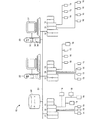
実施例のエントリ325は、警報73Aに対応するプロセス制御警報オブジェクトをプロセス制御システムのヒストリアン・データベースの中の事象番号4622とリンクする。警報73Aがプロセス制御プラントの中で断続的に発生し、プラントオペレータが警報73Aの断続性の原因を判定することに困難を感じる場合を想定する。あるオペレータは、事象番号4622と警報73Aとの間に因果関係を発見することがある。オペレータは、警報73Aに対応するプロセス制御オブジェクトと事象番号4622とをリンクする動的リンク型グラフィカル・メッセージを作成することがある。作成されたメッセージは、エントリ325として、動的リンク型グラフィカル・メッセージ・データベース300に記入されることがある(図3Aに示されている)。
エントリ325に対応する図3の対応する電子付箋328の図形は、警報73Aまたは事象番号4622のいずれかの表現が表示されるときに表示されることがある。電子付箋328は、動的リンク型グラフィカル・メッセージの題目、例えば、事象番号4622および/または警報73Aの標識を表示する主要なフィールド330を有することがある。ユーザが付加的なテキストを記入することがある付加的なフィールド332が電子付箋328にさらに現れることがある。付加的なテキストは、図3Aのエントリ325のための任意フィールド315に記憶されることがある。
The corresponding electronic
図3Aのデータベース300は、動的リンク型グラフィカル・メッセージに関するいくつかの興味深い、有利な特徴を実証している。第一に、プロセス制御システムの中の必ずしも全部の動的リンク型メッセージがそれぞれの内容を同じ集中型プロセス制御データベースに記憶させるために必要とされるわけではない。図3Aでは、エントリ320および322は電子業務日誌に記憶され、エントリ325がヒストリアン・データベースに記憶される。実際に、動的リンク型グラフィカル・メッセージ・データベース300は、プロセス制御システムと関連付けられたありとあらゆる集中型データベースと共に動作することがある。
The
第二に、プロセス制御オブジェクトは、表示ビューに対応するオブジェクトでもよく、あるいは、表示ビューのインスタンスに対応するオブジェクトであるという場合さえある。例えば、エントリ322に対応して、表示ビュー番号48のインスタンス「B」がアクセスされるとき、電子業務日誌エントリ番号7920にリンクされた電子付箋は表示されることがある。表示ビュー番号48の他のインスタンスは、エントリ322に対応する電子付箋を表示しないことになる。一般に、動的リンク型グラフィカル・メッセージは、動的リンク型グラフィカル・メッセージのコンフィギュレーションを必要とすることなく、データベース300を介してプロセス制御システム内部のオブジェクト・クラスまたはサブクラスのいずれかのレベルと関連付けられることがある。
Second, the process control object may be an object corresponding to the display view, or even an object corresponding to an instance of the display view. For example, when the instance “B” of the display view number 48 is accessed corresponding to the
同様に、動的リンク型グラフィカル・メッセージ・データベース300は一般にプロセス制御システムにおいて利用可能なハイパーリンクの記録を提供するが、動的リンク型グラフィカル・メッセージ・データベース300の中のエントリは一時的でもよいことに注意すべきである。例えば、データベース300の中のエントリは、対応する動的リンク型グラフィカル・メッセージが削除されるときに削除されることがある。動的リンク型グラフィカル・メッセージが削除され、動的リンク型グラフィカル・メッセージ・データベース300から除去された後であっても、しかし、対応する集中型データベース・エントリの内容(例えば、エントリ320のための電子業務日誌エントリ番号6379、エントリ322のための電子業務日誌エントリ番号7920、および、エントリ325のための事象データベース・エントリ番号4622)は、それぞれの集中型プロセス制御データベースの中に依然として維持されることがある。
Similarly, although the dynamic link
図4は、プロセス制御システムにおいて動的リンク型グラフィカル・メッセージを提供する方法400の実施形態を表している。方法400の実施形態は、図1のプロセス制御プラント10の実施形態と、図2Aおよび2Bに示された動的リンク型グラフィカル・メッセージおよびその作成と、および/または、図3Aの動的リンク型グラフィカル・メッセージ・データベースとに従って動作することがある。
FIG. 4 represents an embodiment of a
方法400のスタート402で、動的リンク型グラフィカル・メッセージの身元と対応する内容とを含む動的リンク型グラフィカル・メッセージが作成405されることがある。動的リンク型グラフィカル・メッセージはユーザによって作成405されることがある。別の実施形態では、動的リンク型グラフィカル・メッセージは、例えば、スクリプトを用いて、プロセス制御システムによって自動的に作成405されることがある。さらに別の実施形態では、動的リンク型グラフィカル・メッセージはプロセス制御オブジェクトのコンフィギュレーション時に作成405されることがある。
At
動的リンク型グラフィカル・メッセージが作成405される車両は、例えば、ユーザによる注記の「作成」または「追加」操作または同等のものの選択に応答する管理運転を含むことがある。注記「作成」または「追加」オプションは、「削除」、「修正」、「リンク」および他の操作を含む動的リンク型グラフィカル・メッセージ管理操作の組のうちの1つでもよい。操作の組は、例えば、表示ビュー上のプロセス制御オブジェクトが選択されるときに(図2Bに示されているように)、または、プロセス制御オブジェクトがプロセス制御システムの中で利用可能なプロセス制御オブジェクトのリストから選択されるときに、プロセス制御オブジェクト・ユーザ・インターフェイスを介して供給されることがある。代替的または付加的に、動的リンク型グラフィカル・メッセージのための操作の組は、利用可能なユーザ・インターフェイスを介して、プロセス制御システムの集中型データベースへ、例えば、電子業務日誌ユーザ・インターフェイスまたは利用可能なユーザ・インターフェイスを介して、事象、連続、バッチ、もしくは、他のタイプの集中型データベースへ供給されることがある。一部の実施形態では、動的リンク型グラフィカル・メッセージのための操作の組は、ディスプレイ上のユーザ・インターフェイス画面を介して提供されることがある。例えば、操作の組は、ユーザ・インターフェイス画面上のドロップ・ダウン・メニューまたは選択可能なアイコンを介して提供されることがある。一部の実施形態では、動的リンク型グラフィカル・メッセージのための操作の組は、図3Aに示されている動的リンク型グラフィカル・メッセージ・データベース300のような動的リンク型グラフィカル・メッセージ・データベースに特有であるユーザ・インターフェイスを介して提供されることがある。一部の実施形態では、動的リンク型グラフィカル・メッセージの作成405は、作成されたメッセージの内容を記憶することを含む。
The vehicle for which the dynamically linked graphical message is created 405 may include, for example, a management operation that responds to a user's selection of a “create” or “add” operation of an annotation or the like. Note The “Create” or “Add” option may be one of a set of dynamically linked graphical message management operations including “Delete”, “Modify”, “Link” and other operations. The set of operations is, for example, when a process control object on the display view is selected (as shown in FIG. 2B), or a process control object that is available in the process control system. May be supplied through a process control object user interface when selected from a list of Alternatively or additionally, a set of operations for dynamically linked graphical messages can be sent to a centralized database of process control systems via an available user interface, e.g., an electronic business diary user interface or It may be fed to an event, continuous, batch, or other type of centralized database via an available user interface. In some embodiments, a set of operations for dynamically linked graphical messages may be provided via a user interface screen on the display. For example, the set of operations may be provided via a drop down menu or selectable icon on the user interface screen. In some embodiments, the set of operations for dynamically linked graphical messages is a dynamically linked graphical message database, such as the dynamically linked
ブロック408で、作成された動的リンク型グラフィカル・メッセージの内容(例えば、1個以上のフィールド212−215の中の内容)がプロセス制御システムの中のプロセス制御オブジェクトと関連付け、または、リンクされることがある。関連付けまたはリンキングは、ドラッグ・アンド・ドロップ操作によって、管理操作の組から選択された「リンク」操作によって、データエントリによって、または、何らかの他のコマンドによって実行されることがある。一部の実施形態では、動的リンク型グラフィカル・メッセージのリンキング408は、リンクされたメッセージの内容を記憶することを含み、場合によっては、プロセス制御オブジェクトへのリンクの標識を記憶することも含む。
At
ブロック410で、作成された動的リンク型グラフィカル・メッセージの内容は、(まだ記憶されていない場合)プロセス制御システムの1つ以上の集中型データベース、例えば、電子業務日誌、ヒストリアン・データベース、または、何らかの他の集中型データベースに記憶されることがある。典型的に、プロセッサ制御システムの集中型データベースは、コンフィギュレーション・データベースから分離した既存の利用可能な集中型データベースでもよく、内容はプロセス制御オブジェクトの記憶場所とは独立した場所に記憶されることがある。例えば、プロセス制御オブジェクトは、プロセス制御オブジェクトまたはコンフィギュレーション・データベースに記憶されることがあるが、動的リンク型グラフィカル・メッセージの内容は電子文書リポジトリに記憶されることがある。
At
ブロック412で、動的リンク型グラフィカル・オブジェクトは、図3Aのデータベース300のような動的リンク型グラフィカル・メッセージ・データベースの中にエントリとして記憶される。動的リンク型グラフィカル・メッセージ・データベースの記憶されたエントリは、プロセス制御オブジェクトの標識、および、動的リンク型グラフィカル・オブジェクトの内容が記憶されている集中型データベース・エントリの標識を含むことがある。
At
プロセス制御オブジェクト表現を含む表示ビューのランタイム時に(ブロック415)、ハイパーリンクがプロセス制御オブジェクトと集中型データベース・エントリに記憶された動的リンク型グラフィカル・メッセージの内容(例えば、フィールド212−225のうちの1個以上の中の内容)との間に確立される。ブロック418で、電子付箋画像がプロセス制御オブジェクトの表現に近接してアクセスされた表示ビュー上に提示または表示されることがある。電子付箋画像上のフィールドは、ハイパーリンクを介して、集中型データベース・エントリからの内容の一部を表示することがある。
At runtime of the display view containing the process control object representation (block 415), the contents of the dynamic link graphical message (eg, out of fields 212-225) where the hyperlinks are stored in the process control object and the centralized database entry. The contents of one or more of the above. At
実際に、プロセス制御オブジェクトの表現を含むいずれかの表示ビューのランタイム時に、電子付箋がプロセス制御オブジェクトの表現に近接して提示または表示されることがある。さらに、プロセス制御オブジェクトのサブクラス・オブジェクトの表現を含むいずれかの表示ビューは、サブクラス・オブジェクトの表現に近接して電子付箋をさらに提示または表示することがある。最後に、ブロック420で、方法400は終了することがある。
In fact, at the runtime of any display view that includes a representation of a process control object, an electronic sticky note may be presented or displayed in close proximity to the representation of the process control object. In addition, any display view that includes a representation of a subclass object of a process control object may further present or display an electronic sticky note in proximity to the representation of the subclass object. Finally, at
図5は、プロセス制御システムで用いられる動的リンク型グラフィカル・メッセージング・システム500の実施形態を表している。システム500の実施形態は、図1に示されたプロセス制御システムおよびプロセス制御プラントの実施形態に組み込まれるか、または、図1に示されたプロセス制御システムおよびプラント10の実施形態と共に動作することがある。システム500の実施形態は、必要に応じて、図2Aおよび2Bに示された動的リンク型グラフィカル・メッセージの実施形態、図3Aの動的リンク型グラフィカル・メッセージ・データベース300の実施形態、および/または、図4の方法400の実施形態に従って動作することがある。
FIG. 5 illustrates an embodiment of a dynamically linked
動的リンク型グラフィカル・メッセージング・システム500は、例えば、図1のホストまたはオペレータ・ワークステーション20、22でもよいコンピューティング機器502を含むことがある。一部の実施形態では、コンピューティング機器502は、プロセスプラントまたはプロセス制御システム自体の一部でなくてもよいが、ネットワーク・リンク505を介して図1のホストまたはオペレータ・ワークステーション20、22のようなプロセスプラント制御システムのコンピュータに通信可能に連結されることがある。リンク505は、直接接続でも遠隔接続でもよく、有線でも無線でもよい。リンク505は、いずれかの公衆または私設ネットワークへのネットワーク接続を提供することがある。一般に、ネットワーク・リンク505は、技術的に知られているいずれかの公知のネットワーキング技術で作られていることがある。
The dynamically linked
コンピューティング機器502は、プロセッサ508およびプロセッサ508によりアクセス可能であるメモリ510を有することがある。メモリ510は、プロセッサ508によって実行可能であるコンピュータ実行可能な命令が記憶されているコンピュータ読み取り可能な記憶媒体でもよい。図5に示されたコンピューティング機器502は1個のプロセッサ508と1個のメモリ510だけを明らかにしているが、一部の実施形態では、コンピューティング機器502は、複数のプロセッサ508および/または複数のメモリ510を有することがある。同様に、メモリ510は、コンピューティング機器502の内部に収容されているように図示されているが、一部の実施形態では、メモリ510はコンピューティング機器502の外部に位置していてもよいが、依然としてプロセッサ508によってリモートアクセスまたはローカルアクセスされることがある。
The
コンピューティング機器502は、ディスプレイ512およびユーザ・インターフェイス515を含むことがある。例えば、ディスプレイ512はスクリーンでもよく、ユーザ・インターフェイス515は、キーボード、カーソル、タッチスクリーン、音声作動システムなどのうちの少なくとも1つを含むことがある。ディスプレイ512およびユーザ・インターフェイス515は部分的または完全に統合されてもよく、または、通信可能に連結されてもよい。一般に、プロセッサ508、メモリ510、ディスプレイ512およびユーザ・インターフェイス515はそれぞれが技術的に知られている形式をとることがある。
コンピューティング機器502は、多数の異なるコンピューティング機器コンフィギュレーションを包含することがある。例えば、コンピューティング機器502は、ハンドヘルド型機器、携帯電話機、マルチプロセッサ・システム、マイクロプロセッサ・ベースまたはプログラマブル・コンシューマ・エレクトロニクス、ネットワークPC、ミニコンピュータ、メインフレームコンピュータ、携帯型コンピューティングまたは通信機器、および/または、視覚的表示と別のコンピューティング機器との直接的または間接的な通信の両方の能力のある他のコンピューティング機器において実現されることがある。
The
コンピューティング機器502は、リンク518を介して、図1のデータベース28のような集中型プロセス制御システム・データベース520に通信可能に連結されることがある。コンピューティング機器502が図1のワークステーション20、22のうちの一方のようなプロセス制御システムのエンティティである実施形態では、コンピューティング機器502は、システム10のデータハイウェイ24を介して集中型プロセス制御データベース520に連結されることがある。コンピューティング機器502がプロセス制御プラントのエンティティではないが、プロセス制御プラントシステムに通信可能に結合されている実施形態では、コンピューティング機器502は、データベース520と通信するため(例えば、図1では、データハイウェイ24を越えてデータベース28と通信するため)、リンク518を介して、プロセス制御プラントシステム10の中間ゲートウェイ(図示せず)に連結されることがある。一部の実施形態では、リンク505およびリンク518は同じリンクでもよく、他の実施形態では、異なるリンクでもよい。
プロセス制御システムの集中型データベース520は図5では単一のデータベースとして表現されているが、参照番号520は2つ以上の集中型データベースを表現することがある。例えば、プロセス制御システムは、プロセス制御データが履歴目的のため記録される、連続履歴データベース、離散事象データベース、および/または、バッチ・ヒストリアン・データベースのような複数のデータベースを含むことがある。集中型データベース520は、プロセス制御システムで使用される1つ以上のヒストリアン・データベースを表現することがある。集中型データベース520は、文書リポジトリ・データベース、知識オブジェクト・データベース、電子業務日誌、または、それ以外の他の集中型データベースを表現することがある。集中型データベース520は、図3Aの動的リンク型グラフィカル・メッセージ・データベース300を含むことも含まないこともある。典型的に、集中型データベース520は、プロセス制御システムにおけるコンフィギュレーション・データベースから物理的および/または論理的に分離していることがある。
Although the
コンピューティング機器502は、メモリ510に記憶された動的リンク型グラフィカル・メッセージ・プロバイダ522を有することがある。動的リンク型グラフィカル・メッセージ・プロバイダ522は、コンピュータ実行可能な命令、データ構造、プログラムモジュール、および、メモリ510に記憶され、プロセッサ508によって実行可能であり、かつ、アクセス可能である他のデータによって実現されることがある。分散型コンピューティング環境では、動的リンク型グラフィカル・メッセージ・プロバイダ522のコンピュータ実行可能な命令、データ構造、プログラムモジュールなどが、ローカル・メモリ・ストレージ・デバイスおよびリモート・メモリ・ストレージ・デバイスの両方に、例えば、プロセスプラント10のワークステーション20、22と、プロセス制御プラントシステム10の外部にあるコンピューティング機器との両方に位置していてもよい。
The
動的リンク型グラフィカル・メッセージ・プロバイダ522は、図2Aに記載された動的リンク型グラフィカル・メッセージのような動的リンク型グラフィカル・メッセージの実施形態を提供するために、プロセッサによって実行されるコンピュータ実行可能な命令を含むことがある。例えば、動的リンク型グラフィカル・メッセージ・プロバイダ522は、集中型データベース520のエントリに記憶された内容とプロセス制御オブジェクトへのリンクとを含む動的リンク型グラフィカル・メッセージを作成することがある。動的リンク型グラフィカル・メッセージに対応する情報は、他の集中型データベース情報から論理的に分離された形で、メモリ510に常駐するか、または、集中型データベース520に常駐する動的リンク型グラフィカル・メッセージ・データベース300に記憶されることがある。動的リンク型グラフィカル・メッセージ・プロバイダ522は、表示ビューのランタイム時に内容とプロセス制御オブジェクトとの間にハイパーリンクを確立し、プロセス制御オブジェクトの表現に近接して表示ビュー上に集中型データベース520のエントリの内容を格納している電子付箋を表示することがある。動的リンク型グラフィカル・メッセージの削除を受けて、動的リンク型グラフィカル・メッセージ・プロバイダ522は表示ビューから電子付箋を削除し、ハイパーリンクを無効にすることがあるが、集中型データベース・エントリの内容は維持されることがある。
A dynamically linked
動的リンク型グラフィカル・メッセージ・プロバイダ522は、図2Aおよび2Bに関して前述されているような、プロセス制御システムにおいて動的リンク型グラフィカル・メッセージを管理するために用いられる管理操作の組(例えば、「追加」、「削除」、「リンク」、「修正」など)をさらに提供することがある。動的リンク型グラフィカル・メッセージ・プロバイダ522は、データベース300自体を提供すること、検索メカニズムを提供すること、エントリをポピュレートおよび逆ポピュレートすることなどを含み、図3の動的リンク型グラフィカル・メッセージ・データベース300の実施形態を管理することがある。
The dynamically linked
実際に、動的リンク型グラフィカル・メッセージ・プロバイダ522は、図2Aおよび2Bの動的リンク型グラフィカル・メッセージのいずれかの実施形態と、図3Aの動的リンク型グラフィカル・メッセージ・データベース300のいずれかの実施形態と、図4の方法400のいずれかの実施形態とをサポートすることがある。
In fact, the dynamic link
本開示は、数あるコンポーネントの中で、ハードウェア上で実行されるソフトウェアおよび/またはファームウェアを含む実施例の方法およびシステムを記載するが、これらの実施例は単に例示的であり、限定的であるとして見なされるべきでないことに注意を要する。例えば、ハードウェア・コンポーネント、ソフトウェア・コンポーネントおよびファームウェア・コンポーネントのいずれかまたは全部が、ハードウェアだけで、ソフトウェアだけで、または、ハードウェアおよびソフトウェアのいずれかの組み合わせで具現化可能であると考えられる。従って、本開示は実施例の方法および装置を記載するが、当業者は、与えられた実施例がこのような方法およびシステムを実施するための唯一の方法でないことが直ぐにわかるであろう。 Although this disclosure describes example methods and systems that include software and / or firmware running on hardware, among other components, these examples are merely illustrative and limited. Note that it should not be considered as being. For example, any or all of the hardware component, software component, and firmware component may be embodied in hardware alone, software alone, or any combination of hardware and software. . Thus, although this disclosure describes example methods and apparatus, those of ordinary skill in the art will readily appreciate that a given example is not the only way to implement such a method and system.
実施されるとき、本明細書中に記載されたコンピュータ読み取り可能な命令またはソフトウェアのいずれかは、磁気ディスク、レーザディスク、もしくは、他の記憶媒体、コンピュータもしくはプロセッサのRAMまたはROM、携帯型メモリなどのようないずれかのコンピュータ記憶可能な記憶媒体またはメモリに記憶されることがある。同様に、このソフトウェアは、例えば、コンピュータ読み取り可能なディスクもしくは他の可搬型コンピュータ記憶メカニズム、または、電話回線、インターネット、ワールド・ワイド・ウェブ、いずれかの他のローカル・エリア・ネットワークもしくはワイド・エリア・ネットワークなどのような通信チャネルを含む公知または所望の配信方法を使用して、ユーザ、プロセスプラント、または、オペレータ・ワークステーションへ配信されることがある(この配信は、可搬型記憶媒体によってこのようなソフトウェアを提供することと同じであるか、または、互換性があると考えられる)。さらに、このソフトウェアは、変調または暗号化なしで直接的に提供されることがあり、または、通信チャネルを介して送信される前にいずれかの適当な変調搬送波および/または暗号化技術を使用して変調および/または暗号化されることがある。 When implemented, any of the computer-readable instructions or software described herein may be a magnetic disk, laser disk, or other storage medium, computer or processor RAM or ROM, portable memory, etc. May be stored in any computer-storable storage medium or memory. Similarly, the software can be, for example, a computer readable disk or other portable computer storage mechanism, or a telephone line, the Internet, the World Wide Web, any other local area network or wide area. May be delivered to users, process plants, or operator workstations using known or desired delivery methods including communication channels such as networks etc. (this delivery may be performed by a portable storage medium) Is considered the same as or is compatible with providing such software). In addition, the software may be provided directly without modulation or encryption, or using any suitable modulated carrier and / or encryption technique prior to being transmitted over the communication channel. May be modulated and / or encrypted.
本発明は、発明の単なる例示であることが意図され、限定であることが意図されていない特定の実施例に関して記載されているが、変更、追加または削除が、発明の精神および範囲から逸脱することなく、開示された実施形態に行われることは当業者に明白である。 While the invention has been described with reference to specific embodiments which are intended to be merely exemplary of the invention and are not intended to be limiting, modifications, additions or deletions depart from the spirit and scope of the invention. It will be apparent to those skilled in the art without departing from the disclosed embodiments.
Claims (26)
プロセッサ、メモリおよびディスプレイを有し、前記プロセス制御システムと通信する複数のコンピューティング機器と、
前記コンピューティング機器の前記メモリに記憶され、
ハイパーリンクとフィールドを含む電子付箋画像とを含む動的リンク型グラフィカル・メッセージを作成し、
前記電子付箋画像の前記フィールドの内容を前記プロセス制御システムが利用できる集中型データベースのエントリに記憶し、
前記電子付箋画像の前記フィールドの前記内容を前記プロセス制御システムの中に構成されたプロセス制御オブジェクトと関連付け、
前記ディスプレイ上の前記プロセス制御オブジェクトの表現を含む表示ビューのランタイム中に、前記フィールドの前記内容と前記プロセス制御オブジェクトとの間に前記ハイパーリンクを確立し、
前記表示ビュー上の前記プロセス制御オブジェクトの前記表現と共に、前記フィールドの前記内容を含む前記電子付箋画像を提示するため、
前記プロセッサによって実行可能である動的リンク型グラフィカル・メッセージ・プロバイダのためのコンピュータ実行可能な命令と、
を備え、
前記動的リンク型グラフィカル・メッセージは、前記プロセス制御プラントの至る所の前記関連付けられた前記プロセス制御オブジェクトの何れかのランタイムに表示されたインスタンスと共に前記電子付箋画像の自動表示の永続化を生じさせる
動的リンク型グラフィカル・メッセージング・システム。 A dynamically linked graphical messaging system for use in a process control system of a process control plant,
A plurality of computing devices having a processor, a memory and a display and in communication with the process control system;
Stored in the memory of the computing device;
Create a dynamically linked graphical message that includes a hyperlink and an electronic sticky note image that includes a field,
Storing the contents of the field of the electronic sticky note image in a centralized database entry available to the process control system;
Associating the contents of the field of the electronic sticky note image with a process control object configured in the process control system;
Establishing the hyperlink between the content of the field and the process control object during runtime of a display view including a representation of the process control object on the display;
Presenting the electronic sticky note image including the contents of the field along with the representation of the process control object on the display view;
Computer-executable instructions for a dynamically linked graphical message provider executable by the processor;
With
The dynamically linked graphical message causes persistence of the automatic display of the electronic sticky note image along with any instance displayed at runtime of the associated process control object throughout the process control plant. Dynamically linked graphical messaging system.
前記プロセス制御システムと通信する第2のコンピューティング機器をさらに備え、
前記第2のコンピューティング機器が、
前記第2のコンピューティング機器の第2のディスプレイ上の第2の表示ビューのランタイム中に、前記フィールドの前記内容と前記プロセス制御オブジェクトとの間に前記ハイパーリンクを確立し、
前記第2の表示ビュー上の前記プロセス制御オブジェクトの前記表現と共に、前記フィールドの前記内容を含む前記電子付箋画像を提示するため、
前記第2のコンピューティング機器のメモリに記憶され、前記第2のコンピューティング機器のプロセッサによって実行可能である第2のコンピュータ実行可能な命令を含む、
請求項1〜請求項2の何れか1項に記載の動的リンク型グラフィカル・メッセージング・システム。 The computing device is a first computing device, the display view is a first display view, the display is a first display, and the computer executable instructions are first computer executable. Instruction,
A second computing device in communication with the process control system;
The second computing device comprises:
Establishing a hyperlink between the content of the field and the process control object during runtime of a second display view on a second display of the second computing device;
Presenting the electronic sticky note image including the contents of the field along with the representation of the process control object on the second display view;
Second computer executable instructions stored in a memory of the second computing device and executable by a processor of the second computing device;
The dynamic link type graphical messaging system according to claim 1.
前記動的リンク型グラフィカル・メッセージが前記プロセス制御クラス・オブジェクトのサブクラス・オブジェクトに対応する付加的なハイパーリンク組をさらに含み、
前記動的リンク型グラフィカル・メッセージ・プロバイダのための前記コンピュータ実行可能な命令が、
前記電子付箋画像の前記フィールドの前記内容をサブクラス・オブジェクトと関連付け、
前記サブクラス・オブジェクトの表現を含む特有の表示ビューのランタイム中に、前記フィールドの前記内容と前記サブクラス・オブジェクトとの間に付加的なハイパーリンクを確立し、
前記サブクラス・オブジェクトの前記表現と共に、前記フィールドの前記内容を含む前記電子付箋画像を提示するためさらに実行可能である、
請求項1〜請求項3の何れか1項に記載の動的リンク型グラフィカル・メッセージング・システム。 The process control object is a process control class object;
The dynamically linked graphical message further includes an additional hyperlink set corresponding to a subclass object of the process control class object;
The computer executable instructions for the dynamically linked graphical message provider are:
Associating the contents of the field of the electronic sticky note image with a subclass object;
Establishing an additional hyperlink between the content of the field and the subclass object during the runtime of the specific display view containing the representation of the subclass object;
Along with the representation of the subclass object, further executable to present the electronic sticky note image including the content of the field;
The dynamic link type graphical messaging system according to any one of claims 1 to 3.
前記動的リンク型グラフィカル・メッセージに対応する前記動的リンク型グラフィカル・メッセージ・データベースの中のエントリと、
前記動的リンク型グラフィカル・メッセージ・データベースへのユーザ・インターフェイスと、
をさらに備え、
前記コンピュータ実行可能な命令が、前記動的リンク型グラフィカル・メッセージに対応する前記動的リンク型グラフィカル・メッセージ・データベースの中の前記エントリに基づいて前記ハイパーリンクを確立するためさらに実行可能である、
請求項1〜請求項5の何れか1項に記載の動的リンク型グラフィカル・メッセージング・システム。 A dynamically linked graphical message database that is logically independent of the centralized database;
An entry in the dynamically linked graphical message database corresponding to the dynamically linked graphical message;
A user interface to the dynamically linked graphical message database;
Further comprising
The computer-executable instructions are further executable to establish the hyperlink based on the entry in the dynamically linked graphical message database corresponding to the dynamically linked graphical message;
The dynamic link type graphical messaging system according to any one of claims 1 to 5.
・インターフェイス、または、前記表示ビューのためのユーザ・インターフェイスのうちの少なくとも1つを介してアクセス可能である、請求項10に記載の動的リンク型グラフィカル・メッセージング・システム。 The set of dynamically linked graphical message management operations includes a user interface for the centralized database, a user interface for the process control object, or a user interface for the display view The dynamically linked graphical messaging system of claim 10, wherein the dynamically linked graphical messaging system is accessible via at least one of the following:
前記電子付箋画像の前記外観を修正することが、形状、色、サイズ、動的視覚的特徴、場所、または、フォントのうちの少なくとも1つを修正することを備える、請求項11に記載の動的リンク型グラフィカル・メッセージング・システム。 The modification, which is the dynamic link type graphical message management operation, modifies the content of the selected dynamic link type graphical message, or a specific corresponding to the selected dynamic link type graphical message. Comprising at least one of modifying the appearance of the electronic sticky note image,
The motion of claim 11, wherein modifying the appearance of the electronic sticky note image comprises modifying at least one of shape, color, size, dynamic visual feature, location, or font. Linked graphical messaging system.
サイズ変更可能、
前記ディスプレイ上の異なる場所へ移動可能、
前記ディスプレイの前景への移動または前記ディスプレイの背景への送り出し可能、
非表示または再表示可能、または、
前記ディスプレイのサイズに比例した拡大縮小可能、
のうちの少なくとも1つである、請求項1〜請求項12の何れか1項に記載の動的リンク型グラフィカル・メッセージング・システム。 The electronic sticky note image is
Resizable,
Move to different locations on the display,
Can move the display to the foreground or send it to the background of the display,
Can be hidden or redisplayed, or
Scaleable in proportion to the size of the display,
The dynamically linked graphical messaging system according to claim 1, wherein the system is at least one of the following.
前記ウィンドウが、前記フィールドの前記内容と、前記集中型データベースの前記エントリの少なくとも1つの付加的なデータベースフィールドとを含み、
前記少なくとも1つの付加的なデータベース・フィールドが、作者フィールド、作成日フィールド、タイトルフィールド、メッセージ詳細フィールド、または、満了フィールドのうちの少なくとも1つを含み、
前記ユーザ開始アクションが、ユーザ開始マウス・アクション、ユーザ開始カーソル・アクション、音声コマンド、または、ユーザ開始タッチスクリーン・アクションのうちの少なくとも1つを備える、
請求項1〜請求項13の何れか1項に記載の動的リンク型グラフィカル・メッセージング・システム。 The dynamic link graphical message provider further displays a window in response to a user initiated action corresponding to the electronic sticky note image presented in the display view;
The window includes the content of the field and at least one additional database field of the entry of the centralized database;
The at least one additional database field includes at least one of an author field, a creation date field, a title field, a message detail field, or an expiration field;
The user-initiated action comprises at least one of a user-initiated mouse action, a user-initiated cursor action, a voice command, or a user-initiated touch screen action.
14. A dynamically linked graphical messaging system according to any one of claims 1 to 13.
前記視覚的特徴が、動的リンク型グラフィカル・メッセージ・タイプ、ユーザ識別情報、前記プロセス制御プラントの中での物理的場所、プロセス制御オブジェクト・クラス、または、前記動的リンク型グラフィカル・メッセージの優先度のうちの少なくとも1つに対応する、
請求項1〜請求項14の何れか1項に記載の動的リンク型グラフィカル・メッセージング・システム。 The electronic sticky note image has a visual feature that is at least one of color, shape, font, size, or dynamic attributes;
The visual feature is a dynamic linked graphical message type, user identification information, physical location in the process control plant, process control object class, or priority of the dynamic linked graphical message Corresponding to at least one of the degrees,
15. A dynamically linked graphical messaging system according to any one of claims 1 to 14.
ッセージであって、
前記プロセス制御システムの中で構成された前記プロセス制御システムのプロセス制御オブジェクトの表現と共に、前記プロセス制御システムと通信するコンピューティング機器のディスプレイ上の表示ビューに提示された、フィールドを含む電子付箋画像と、
前記表示ビューのランタイムに確立され、前記プロセス制御システムの少なくとも1つの集中型データベースの中のエントリに記憶されている前記電子付箋画像の前記フィールドの内容を前記プロセス制御オブジェクトにリンクするハイパーリンクと、
前記少なくとも1つの集中型データベースと論理的に独立している動的リンク型グラフィカル・メッセージ・データベースの中で、前記動的リンク型グラフィカル・メッセージの標識、前記プロセス制御オブジェクトの標識、および前記少なくとも1つの集中型データベースの標識を含み、前記プロセス制御オブジェクトのコンフィギュレーションおよび前記表示ビューのコンフィギュレーションを除外するエントリと、
を備える動的リンク型グラフィカル・メッセージ。 A dynamically linked graphical message used in a process control system of a process control plant,
An electronic sticky note image including a field presented in a display view on a display of a computing device in communication with the process control system, with a representation of the process control object of the process control system configured in the process control system; ,
A hyperlink that links the contents of the field of the electronic sticky note image to the process control object that is established at runtime of the display view and stored in an entry in at least one centralized database of the process control system;
In a dynamically linked graphical message database that is logically independent of the at least one centralized database, the dynamically linked graphical message indicator, the process control object indicator, and the at least one An entry containing two centralized database indicators and excluding the configuration of the process control object and the configuration of the display view;
Dynamically linked graphical message with
前記少なくとも1つの付加的なデータベース・フィールドが、前記動的リンク型グラフィカル・メッセージに対応するユーザ開始アクションに応答して前記表示ビューに現れるウィンドウの中に表示され、
前記ユーザ開始アクションが、ユーザ開始マウス・アクションと、ユーザ開始カーソル・アクションと、ユーザ開始音声アクティブ化と、ユーザ開始タッチスクリーン・アクションとのうちの1つを備える、
請求項17に記載の動的リンク型グラフィカル・メッセージ。 The entry in the dynamically linked graphical message database includes a title field, an author field, a message detail field, a creation date field, an expiration field, and a second configured in the process control system. Further comprising at least one additional database field selected from the second hyperlink to the process control object;
The at least one additional database field is displayed in a window that appears in the display view in response to a user-initiated action corresponding to the dynamically linked graphical message;
The user-initiated action comprises one of a user-initiated mouse action, a user-initiated cursor action, a user-initiated voice activation, and a user-initiated touchscreen action.
The dynamically linked graphical message according to claim 17.
前記動的リンク型グラフィカル・メッセージが、各付加的なハイパーリンクが前記フィールドの前記内容を前記クラス・オブジェクトの異なるサブクラス・オブジェクトにリンクする付加的なハイパーリンクの組をさらに含み、
各付加的なハイパーリンクが前記異なるサブクラス・オブジェクトの表現を含む特有の表示ビューのランタイム時に確立される、
請求項17〜請求項19の何れか1項に記載の動的リンク型グラフィカル・メッセージ。 The process control object is a class object;
The dynamically linked graphical message further includes a set of additional hyperlinks, each additional hyperlink linking the contents of the field to a different subclass object of the class object;
Each additional hyperlink is established at runtime in a specific display view that includes a representation of the different subclass objects.
20. A dynamically linked graphical message according to any one of claims 17-19.
前記視覚的特徴が、動的リンク型グラフィカル・メッセージのタイプ、ユーザの権限レベル、前記プロセス制御プラントの中での物理的場所、前記動的リンク型グラフィカル・メッセージの優先度、または、ユーザ指定基準のうちの少なくとも1つに対応する、
請求項17〜請求項21の何れか1項に記載の動的リンク型グラフィカル・メッセージ。 The electronic sticky note image has a visual feature that is at least one of color, shape, font, or dynamic attributes;
The visual feature is a type of a dynamic link graphical message, a user authority level, a physical location in the process control plant, a priority of the dynamic link graphical message, or a user specified criterion Corresponding to at least one of
The dynamic link type graphical message according to any one of claims 17 to 21.
ハイパーリンクとフィールドを含む電子付箋画像とを含む動的リンク型グラフィカル・メッセージを作成するステップと、
前記電子付箋画像の前記フィールドの内容を前記プロセス制御システムが利用できる集中型データベースのエントリに記憶するステップと、
前記フィールドの前記内容を前記プロセス制御システムの中に構成されたプロセス制御オブジェクトと関連付けるステップと、
コンピューティング機器のディスプレイ上の前記プロセス制御オブジェクトの表現を含む表示ビューのランタイム中に、前記フィールドの前記内容と前記プロセス制御オブジェクトとの間に前記ハイパーリンクを確立するステップと、
前記プロセス制御オブジェクトの前記表現と共に、前記フィールドの前記内容を含む前記電子付箋画像を前記表示ビューに提示するステップと、
を備え、
前記動的リンク型グラフィカル・メッセージは、前記プロセス制御プラントの至る所の前記関連付けられた前記プロセス制御オブジェクトの何れかのランタイムに表示されたインスタンスと共に前記電子付箋画像の自動表示の永続化を生じさせる
方法。 A method for providing dynamically linked graphical messages in a process control system of a process control plant, comprising:
Creating a dynamically linked graphical message including a hyperlink and an electronic sticky note image including a field;
Storing the contents of the field of the electronic sticky note image in a centralized database entry available to the process control system;
Associating the contents of the field with a process control object configured in the process control system;
Establishing the hyperlink between the content of the field and the process control object during runtime of a display view including a representation of the process control object on a display of a computing device;
Presenting the electronic sticky note image including the contents of the field along with the representation of the process control object to the display view;
With
The dynamically linked graphical message causes persistence of the automatic display of the electronic sticky note image along with any instance displayed at runtime of the associated process control object throughout the process control plant. Method.
前記プロセス制御システムと通信する第2のコンピューティング機器の第2のディスプレイ上での前記プロセス制御オブジェクトの前記表現を含む第2の表示ビューのランタイム中に、前記フィールドの前記内容と前記プロセス制御オブジェクトとの間に前記ハイパ
ーリンクを確立するステップと、
前記プロセス制御オブジェクトの前記表現と共に、前記フィールドの前記内容を含む前記電子付箋画像を前記第2の表示ビューに提示するステップと、
をさらに備える、請求項23に記載の方法。 The display view is a first display view, the display is a first display, and the computing device is a first computing device;
During runtime of a second display view including the representation of the process control object on a second display of a second computing device in communication with the process control system, the content of the field and the process control object Establishing the hyperlink with
Presenting the electronic sticky note image including the contents of the field along with the representation of the process control object to the second display view;
24. The method of claim 23, further comprising:
前記電子付箋画像の前記フィールドの前記内容を前記プロセス制御クラス・オブジェクトのサブクラス・オブジェクトと関連付けるステップと、
前記サブクラス・オブジェクトの表現を含む特有の表示ビューのランタイム中に、前記フィールドの前記内容と前記サブクラス・オブジェクトとの間に付加的なハイパーリンクを確立するステップと、
前記サブクラス・オブジェクトの前記表現と共に、前記フィールドの前記内容を含む前記電子付箋画像を前記特有の表示ビューに提示するステップと、
をさらに備える、請求項23又は請求項24に記載の方法。 Associating the content of the field with the process control object comprises associating the content of the field with a process control class object;
Associating the content of the field of the electronic sticky note image with a subclass object of the process control class object;
Establishing an additional hyperlink between the contents of the field and the subclass object during the runtime of a specific display view including a representation of the subclass object;
Presenting the electronic sticky note image including the contents of the field along with the representation of the subclass object in the unique display view;
25. The method of claim 23 or claim 24, further comprising:
データベース管理機能の組および検索能力を含む前記動的リンク型グラフィカル・メッセージ・データベースへのユーザ・インターフェイスを提供するステップと、
をさらに備える、請求項23〜請求項25の何れか1項に記載の方法。 Providing a dynamically linked graphical message database including entries corresponding to the dynamically linked graphical messages and excluding the configuration of the process control object and the configuration of the display view;
Providing a user interface to the dynamically linked graphical message database including a set of database management functions and search capabilities;
The method according to any one of claims 23 to 25, further comprising:
Applications Claiming Priority (4)
| Application Number | Priority Date | Filing Date | Title |
|---|---|---|---|
| US24509609P | 2009-09-23 | 2009-09-23 | |
| US61/245,096 | 2009-09-23 | ||
| US12/883,330 US8683317B2 (en) | 2009-09-23 | 2010-09-16 | Dynamically linked graphical messages for process control systems |
| US12/883,330 | 2010-09-16 |
Publications (3)
| Publication Number | Publication Date |
|---|---|
| JP2011070673A JP2011070673A (en) | 2011-04-07 |
| JP2011070673A5 JP2011070673A5 (en) | 2013-10-24 |
| JP5715786B2 true JP5715786B2 (en) | 2015-05-13 |
Family
ID=43065644
Family Applications (1)
| Application Number | Title | Priority Date | Filing Date |
|---|---|---|---|
| JP2010213662A Active JP5715786B2 (en) | 2009-09-23 | 2010-09-24 | Dynamically linked graphical messaging system, dynamically linked graphical message and method |
Country Status (5)
| Country | Link |
|---|---|
| US (1) | US8683317B2 (en) |
| JP (1) | JP5715786B2 (en) |
| CN (1) | CN102033747B (en) |
| DE (1) | DE102010037702A1 (en) |
| GB (1) | GB2473948A (en) |
Families Citing this family (33)
| Publication number | Priority date | Publication date | Assignee | Title |
|---|---|---|---|---|
| US9588669B2 (en) * | 2011-02-17 | 2017-03-07 | T-Mobile Usa, Inc. | Sticky messages |
| JP5434941B2 (en) * | 2011-03-22 | 2014-03-05 | 横河電機株式会社 | Operation monitoring device and operation monitoring method |
| US9581994B2 (en) * | 2011-04-05 | 2017-02-28 | Fisher-Rosemount Systems, Inc. | Methods and apparatus to manage process control resources |
| CN103535070B (en) * | 2011-06-14 | 2016-11-09 | Abb研究有限公司 | Method and apparatus for field apparatus Bandwidth Dynamic Allocation in Process Control System |
| CA2793315A1 (en) * | 2011-10-25 | 2013-04-25 | Kemex Ltd. | A methodology and preferred software that, together, reduce the effort required to write and maintain operating procedures for manufacturing plants and oil and gas facilities |
| JP5958049B2 (en) * | 2012-04-26 | 2016-07-27 | 富士ゼロックス株式会社 | Mount management program and mount management apparatus |
| US20140033113A1 (en) * | 2012-07-30 | 2014-01-30 | Yokogawa Electric Corporation | Method and apparatus for creating a record |
| US11144854B1 (en) * | 2012-09-18 | 2021-10-12 | Taskworld Holdings Pte. Ltd. | Digital pinboard system |
| US20140089619A1 (en) * | 2012-09-27 | 2014-03-27 | Infinera Corporation | Object replication framework for a distributed computing environment |
| US9501208B2 (en) | 2012-10-08 | 2016-11-22 | Fisher-Rosemount Systems, Inc. | Method and apparatus for managing process control configuration |
| US11774927B2 (en) | 2012-10-08 | 2023-10-03 | Fisher-Rosemount Systems, Inc. | Methods and apparatus to provide a role-based user interface |
| US11216159B2 (en) | 2012-10-08 | 2022-01-04 | Fisher-Rosemount Systems, Inc. | Configuration element for graphic elements |
| JP6123631B2 (en) * | 2013-10-28 | 2017-05-10 | 富士ゼロックス株式会社 | Information processing apparatus and information processing program |
| GB2522338B (en) | 2014-01-03 | 2020-12-16 | Fisher Rosemount Systems Inc | Reusable graphical elements with quickly editable features for use in user displays of plant monitoring systems |
| JP5948366B2 (en) * | 2014-05-29 | 2016-07-06 | 京セラドキュメントソリューションズ株式会社 | Document reading apparatus and image forming apparatus |
| US9177225B1 (en) * | 2014-07-03 | 2015-11-03 | Oim Squared Inc. | Interactive content generation |
| KR20160018269A (en) * | 2014-08-08 | 2016-02-17 | 삼성전자주식회사 | Device and method for controlling the same |
| US10310704B2 (en) * | 2014-09-18 | 2019-06-04 | Ademco Inc. | System and method to have location based personalized UI updates on mobile app for connected users in security, video and home automation applications |
| WO2016131207A1 (en) * | 2015-02-16 | 2016-08-25 | 锤子软件(北京)有限公司 | Control method, control apparatus and electronic device |
| US9910644B2 (en) * | 2015-03-03 | 2018-03-06 | Microsoft Technology Licensing, Llc | Integrated note-taking functionality for computing system entities |
| US20160349931A1 (en) * | 2015-05-28 | 2016-12-01 | Rockwell Automation Technologies, Inc. | Responsive user interface for an industrial environment |
| US10229717B1 (en) | 2015-07-24 | 2019-03-12 | Snap, Inc. | Interactive presentation of video content and associated information |
| US10318539B2 (en) | 2016-03-24 | 2019-06-11 | General Electric Company | Method and apparatus for managing information across like-cases |
| US10257342B2 (en) * | 2016-03-31 | 2019-04-09 | Microsoft Technology Licensing, Llc | Validating stateful dynamic links in mobile applications |
| US10671038B2 (en) | 2016-07-15 | 2020-06-02 | Fisher-Rosemount Systems, Inc. | Architecture-independent process control |
| CN106970727A (en) * | 2017-04-20 | 2017-07-21 | 周贤和 | A kind of DALI master controls lcd touch device |
| US10788972B2 (en) * | 2017-10-02 | 2020-09-29 | Fisher-Rosemount Systems, Inc. | Systems and methods for automatically populating a display area with historized process parameters |
| US20190369824A1 (en) * | 2018-05-30 | 2019-12-05 | Thomas Alan Robinson | Computerized system and method for note taking |
| EP3820655B1 (en) * | 2018-07-13 | 2023-06-14 | ABB Schweiz AG | Diagnosis method and apparatus |
| JP2020135341A (en) * | 2019-02-19 | 2020-08-31 | 富士ゼロックス株式会社 | Information processor and information processing program |
| JP7356263B2 (en) * | 2019-05-29 | 2023-10-04 | シャープ株式会社 | Information processing device, information processing method, and information processing program |
| EP3805882B1 (en) * | 2019-10-10 | 2022-06-08 | Siemens Aktiengesellschaft | Control system for a technical installation with a trend curve diagram |
| EP3964905A1 (en) * | 2020-09-04 | 2022-03-09 | Siemens Aktiengesellschaft | User-specific dependencies between digital representations of process objects |
Family Cites Families (23)
| Publication number | Priority date | Publication date | Assignee | Title |
|---|---|---|---|---|
| JP3238205B2 (en) * | 1992-08-12 | 2001-12-10 | 株式会社日立製作所 | Screen tagging method and device |
| CA2339141A1 (en) | 1998-07-30 | 2000-02-10 | Insight Development Corporation | System for capturing, annotating and transmitting images of internet web pages |
| US6691280B1 (en) * | 1999-03-08 | 2004-02-10 | Fisher-Rosemount Systems, Inc. | Use of uniform resource locators in process control system documentation |
| US7191400B1 (en) | 2000-02-03 | 2007-03-13 | Stanford University | Methods for generating and viewing hyperlinked pages |
| AU2001275096A1 (en) | 2000-06-22 | 2002-01-02 | Intel Corporation | Communicating objects between users or applications |
| US20030103071A1 (en) | 2001-09-08 | 2003-06-05 | William Lusen | User interface system for processing documents for display |
| US20030182168A1 (en) | 2002-03-22 | 2003-09-25 | Martha Lyons | Systems and methods for virtual, real-time affinity diagramming collaboration by remotely distributed teams |
| US7010752B2 (en) | 2002-05-03 | 2006-03-07 | Enactex, Inc. | Method for graphical collaboration with unstructured data |
| US7043311B2 (en) * | 2003-02-18 | 2006-05-09 | Fisher-Rosemount Systems, Inc. | Module class objects in a process plant configuration system |
| US7555705B2 (en) | 2003-09-10 | 2009-06-30 | Microsoft Corporation | Annotation management in a pen-based computing system |
| US7519900B2 (en) | 2003-10-24 | 2009-04-14 | Microsoft Corporation | System and method for processing digital annotations |
| US20050091578A1 (en) | 2003-10-24 | 2005-04-28 | Microsoft Corporation | Electronic sticky notes |
| US20070282480A1 (en) | 2003-11-10 | 2007-12-06 | Pannese Patrick D | Methods and systems for controlling a semiconductor fabrication process |
| EP1782227A4 (en) * | 2004-06-23 | 2009-06-03 | Ayman Llc | Method of updating information in an electronic note |
| US7698644B2 (en) | 2005-04-26 | 2010-04-13 | Cisco Technology, Inc. | System and method for displaying sticky notes on a phone |
| US8055727B2 (en) | 2005-09-22 | 2011-11-08 | Fisher-Rosemount Systems, Inc. | Use of a really simple syndication communication format in a process control system |
| JP2007334470A (en) | 2006-06-13 | 2007-12-27 | Fuji Xerox Co Ltd | Information processor and program regarding electronic tag |
| US9245251B2 (en) | 2006-07-20 | 2016-01-26 | International Business Machines Corporation | Managing electronic sticky notes |
| US20080046490A1 (en) | 2006-08-15 | 2008-02-21 | Microsoft Corporation | Intelligent Sticky Notes |
| JP5073281B2 (en) * | 2006-12-12 | 2012-11-14 | 株式会社Pfu | Sticky note display processing apparatus and sticky note display processing method |
| US20090055737A1 (en) * | 2007-08-22 | 2009-02-26 | Andreas Borchardt | Contextual Collaborative Electronic Annotations |
| CN102105876B (en) | 2008-07-25 | 2014-02-19 | 日本电气株式会社 | Electronic sticky note system |
| US20100095198A1 (en) | 2008-10-15 | 2010-04-15 | Apple Inc. | Shared comments for online document collaboration |
-
2010
- 2010-09-16 US US12/883,330 patent/US8683317B2/en active Active
- 2010-09-22 DE DE102010037702A patent/DE102010037702A1/en active Pending
- 2010-09-22 GB GB1015891A patent/GB2473948A/en not_active Withdrawn
- 2010-09-24 JP JP2010213662A patent/JP5715786B2/en active Active
- 2010-09-25 CN CN201010571956.9A patent/CN102033747B/en active Active
Also Published As
| Publication number | Publication date |
|---|---|
| GB2473948A (en) | 2011-03-30 |
| JP2011070673A (en) | 2011-04-07 |
| DE102010037702A1 (en) | 2011-04-21 |
| CN102033747A (en) | 2011-04-27 |
| US20110072382A1 (en) | 2011-03-24 |
| GB201015891D0 (en) | 2010-10-27 |
| US8683317B2 (en) | 2014-03-25 |
| CN102033747B (en) | 2016-08-24 |
Similar Documents
| Publication | Publication Date | Title |
|---|---|---|
| JP5715786B2 (en) | Dynamically linked graphical messaging system, dynamically linked graphical message and method | |
| US11671478B1 (en) | Remote asset monitoring and control | |
| JP7361450B2 (en) | Method and apparatus for streaming to remote devices | |
| JP5723128B2 (en) | Dynamic hyperlinks for process control systems | |
| JP6286511B2 (en) | Scripted graphics in the process environment | |
| JP6611434B2 (en) | Reusable graphical elements with rapidly editable features for use in user display of plant monitoring systems | |
| CN104903799B (en) | Configurable user in Process Control System shows | |
| US9870545B2 (en) | System and method for providing user interface cards | |
| EP2084593B1 (en) | Data quality and status behavior for human machine interface graphics in industrial control and automation systems | |
| US9864963B2 (en) | System and method for providing content-based user interface cards | |
| US20030172371A1 (en) | System and method for managing software applications, particularly manufacturing execution system (MES) applications | |
| JP2015143994A (en) | Process control management system, computer readable memory medium, and sidebar application | |
| US20170293418A1 (en) | Apparatus and method for generating industrial process graphics | |
| JP6759942B2 (en) | Application development environment provision system, application development environment provision method, application development environment provision program, terminal device, application display method, and application display program | |
| JP2018055565A (en) | Application development environment providing system, application development environment providing method, application development environment providing program, and information processing device | |
| EP2419813B1 (en) | A supervisory control system for controlling a technical system, a method and computer program products |
Legal Events
| Date | Code | Title | Description |
|---|---|---|---|
| A521 | Request for written amendment filed |
Free format text: JAPANESE INTERMEDIATE CODE: A523 Effective date: 20130909 |
|
| A621 | Written request for application examination |
Free format text: JAPANESE INTERMEDIATE CODE: A621 Effective date: 20130909 |
|
| A977 | Report on retrieval |
Free format text: JAPANESE INTERMEDIATE CODE: A971007 Effective date: 20140611 |
|
| A131 | Notification of reasons for refusal |
Free format text: JAPANESE INTERMEDIATE CODE: A131 Effective date: 20140624 |
|
| A521 | Request for written amendment filed |
Free format text: JAPANESE INTERMEDIATE CODE: A523 Effective date: 20140919 |
|
| TRDD | Decision of grant or rejection written | ||
| A01 | Written decision to grant a patent or to grant a registration (utility model) |
Free format text: JAPANESE INTERMEDIATE CODE: A01 Effective date: 20150217 |
|
| A61 | First payment of annual fees (during grant procedure) |
Free format text: JAPANESE INTERMEDIATE CODE: A61 Effective date: 20150316 |
|
| R150 | Certificate of patent or registration of utility model |
Ref document number: 5715786 Country of ref document: JP Free format text: JAPANESE INTERMEDIATE CODE: R150 |
|
| R250 | Receipt of annual fees |
Free format text: JAPANESE INTERMEDIATE CODE: R250 |
|
| R250 | Receipt of annual fees |
Free format text: JAPANESE INTERMEDIATE CODE: R250 |
|
| R250 | Receipt of annual fees |
Free format text: JAPANESE INTERMEDIATE CODE: R250 |
|
| R250 | Receipt of annual fees |
Free format text: JAPANESE INTERMEDIATE CODE: R250 |
|
| R250 | Receipt of annual fees |
Free format text: JAPANESE INTERMEDIATE CODE: R250 |
|
| R250 | Receipt of annual fees |
Free format text: JAPANESE INTERMEDIATE CODE: R250 |
|
| R250 | Receipt of annual fees |
Free format text: JAPANESE INTERMEDIATE CODE: R250 |