JP5715621B2 - Ultrasonic signal compression - Google Patents
Ultrasonic signal compression Download PDFInfo
- Publication number
- JP5715621B2 JP5715621B2 JP2012514019A JP2012514019A JP5715621B2 JP 5715621 B2 JP5715621 B2 JP 5715621B2 JP 2012514019 A JP2012514019 A JP 2012514019A JP 2012514019 A JP2012514019 A JP 2012514019A JP 5715621 B2 JP5715621 B2 JP 5715621B2
- Authority
- JP
- Japan
- Prior art keywords
- samples
- sample
- sequences
- signal
- analog
- Prior art date
- Legal status (The legal status is an assumption and is not a legal conclusion. Google has not performed a legal analysis and makes no representation as to the accuracy of the status listed.)
- Active
Links
- 238000007906 compression Methods 0.000 title claims description 136
- 230000006835 compression Effects 0.000 title claims description 136
- 238000002604 ultrasonography Methods 0.000 claims description 152
- 238000012546 transfer Methods 0.000 claims description 47
- 238000000034 method Methods 0.000 claims description 36
- 238000012545 processing Methods 0.000 claims description 34
- 238000007493 shaping process Methods 0.000 claims description 30
- 238000005070 sampling Methods 0.000 claims description 27
- 238000012285 ultrasound imaging Methods 0.000 claims description 13
- 239000000523 sample Substances 0.000 description 172
- 238000010586 diagram Methods 0.000 description 36
- 238000007667 floating Methods 0.000 description 23
- 238000006243 chemical reaction Methods 0.000 description 22
- 230000006837 decompression Effects 0.000 description 21
- 230000005540 biological transmission Effects 0.000 description 11
- 238000013144 data compression Methods 0.000 description 11
- 238000001514 detection method Methods 0.000 description 10
- 230000006870 function Effects 0.000 description 10
- 230000008901 benefit Effects 0.000 description 8
- 238000001914 filtration Methods 0.000 description 8
- 238000013507 mapping Methods 0.000 description 8
- 238000004891 communication Methods 0.000 description 7
- 230000005284 excitation Effects 0.000 description 7
- 230000008569 process Effects 0.000 description 7
- 230000015572 biosynthetic process Effects 0.000 description 6
- 238000002592 echocardiography Methods 0.000 description 6
- 230000010354 integration Effects 0.000 description 6
- 238000003384 imaging method Methods 0.000 description 5
- 230000004044 response Effects 0.000 description 5
- 101100458289 Drosophila melanogaster msps gene Proteins 0.000 description 3
- 238000004458 analytical method Methods 0.000 description 3
- 230000008859 change Effects 0.000 description 3
- 230000007423 decrease Effects 0.000 description 3
- 230000014509 gene expression Effects 0.000 description 3
- 239000013598 vector Substances 0.000 description 3
- HPTJABJPZMULFH-UHFFFAOYSA-N 12-[(Cyclohexylcarbamoyl)amino]dodecanoic acid Chemical compound OC(=O)CCCCCCCCCCCNC(=O)NC1CCCCC1 HPTJABJPZMULFH-UHFFFAOYSA-N 0.000 description 2
- 230000003044 adaptive effect Effects 0.000 description 2
- 238000003491 array Methods 0.000 description 2
- 238000004364 calculation method Methods 0.000 description 2
- 238000002059 diagnostic imaging Methods 0.000 description 2
- 229940079593 drug Drugs 0.000 description 2
- 239000003814 drug Substances 0.000 description 2
- 230000000694 effects Effects 0.000 description 2
- 238000005516 engineering process Methods 0.000 description 2
- 239000000284 extract Substances 0.000 description 2
- 238000012986 modification Methods 0.000 description 2
- 230000004048 modification Effects 0.000 description 2
- 238000013139 quantization Methods 0.000 description 2
- 230000011664 signaling Effects 0.000 description 2
- 238000003860 storage Methods 0.000 description 2
- 230000009466 transformation Effects 0.000 description 2
- 238000007476 Maximum Likelihood Methods 0.000 description 1
- 238000012952 Resampling Methods 0.000 description 1
- 101100434411 Saccharomyces cerevisiae (strain ATCC 204508 / S288c) ADH1 gene Proteins 0.000 description 1
- 101150102866 adc1 gene Proteins 0.000 description 1
- 210000003484 anatomy Anatomy 0.000 description 1
- 230000003190 augmentative effect Effects 0.000 description 1
- 239000008280 blood Substances 0.000 description 1
- 210000004369 blood Anatomy 0.000 description 1
- 230000000052 comparative effect Effects 0.000 description 1
- 230000003750 conditioning effect Effects 0.000 description 1
- 238000005520 cutting process Methods 0.000 description 1
- 230000001934 delay Effects 0.000 description 1
- 238000003745 diagnosis Methods 0.000 description 1
- 238000011143 downstream manufacturing Methods 0.000 description 1
- 230000009977 dual effect Effects 0.000 description 1
- 230000002708 enhancing effect Effects 0.000 description 1
- 239000012530 fluid Substances 0.000 description 1
- 239000000463 material Substances 0.000 description 1
- 239000013307 optical fiber Substances 0.000 description 1
- 238000005457 optimization Methods 0.000 description 1
- 230000002093 peripheral effect Effects 0.000 description 1
- 238000002360 preparation method Methods 0.000 description 1
- 230000009467 reduction Effects 0.000 description 1
- 230000000717 retained effect Effects 0.000 description 1
- 239000004065 semiconductor Substances 0.000 description 1
- 238000000926 separation method Methods 0.000 description 1
- 238000000527 sonication Methods 0.000 description 1
- 238000001228 spectrum Methods 0.000 description 1
- 238000006467 substitution reaction Methods 0.000 description 1
- 238000000844 transformation Methods 0.000 description 1
- 230000000007 visual effect Effects 0.000 description 1
Images


Classifications
-
- G—PHYSICS
- G01—MEASURING; TESTING
- G01S—RADIO DIRECTION-FINDING; RADIO NAVIGATION; DETERMINING DISTANCE OR VELOCITY BY USE OF RADIO WAVES; LOCATING OR PRESENCE-DETECTING BY USE OF THE REFLECTION OR RERADIATION OF RADIO WAVES; ANALOGOUS ARRANGEMENTS USING OTHER WAVES
- G01S7/00—Details of systems according to groups G01S13/00, G01S15/00, G01S17/00
- G01S7/52—Details of systems according to groups G01S13/00, G01S15/00, G01S17/00 of systems according to group G01S15/00
- G01S7/52017—Details of systems according to groups G01S13/00, G01S15/00, G01S17/00 of systems according to group G01S15/00 particularly adapted to short-range imaging
- G01S7/52023—Details of receivers
- G01S7/52034—Data rate converters
-
- A—HUMAN NECESSITIES
- A61—MEDICAL OR VETERINARY SCIENCE; HYGIENE
- A61B—DIAGNOSIS; SURGERY; IDENTIFICATION
- A61B8/00—Diagnosis using ultrasonic, sonic or infrasonic waves
- A61B8/48—Diagnostic techniques
- A61B8/483—Diagnostic techniques involving the acquisition of a 3D volume of data
Landscapes
- Engineering & Computer Science (AREA)
- Health & Medical Sciences (AREA)
- Life Sciences & Earth Sciences (AREA)
- Physics & Mathematics (AREA)
- Surgery (AREA)
- Heart & Thoracic Surgery (AREA)
- Veterinary Medicine (AREA)
- Public Health (AREA)
- General Health & Medical Sciences (AREA)
- Animal Behavior & Ethology (AREA)
- Biophysics (AREA)
- Nuclear Medicine, Radiotherapy & Molecular Imaging (AREA)
- Pathology (AREA)
- Radiology & Medical Imaging (AREA)
- Biomedical Technology (AREA)
- Molecular Biology (AREA)
- Medical Informatics (AREA)
- Remote Sensing (AREA)
- Computer Networks & Wireless Communication (AREA)
- General Physics & Mathematics (AREA)
- Radar, Positioning & Navigation (AREA)
- Ultra Sonic Daignosis Equipment (AREA)
- Computer Vision & Pattern Recognition (AREA)
- Theoretical Computer Science (AREA)
- Acoustics & Sound (AREA)
- Multimedia (AREA)
Description
本発明は、超音波トランスジューサにより受信された超音波信号データの圧縮に係り、より詳細には、超音波信号サンプルを、アナログ/デジタル変換の後であって且つビーム成形、検出及び画像形成の前に圧縮することに係る。 The present invention relates to compression of ultrasound signal data received by an ultrasound transducer, and more particularly, ultrasound signal samples after analog / digital conversion and prior to beam shaping, detection and imaging. It relates to compression.
医療用超音波システムは、臨床医により対象者に置かれたトランスジューサから超音波ビームを送信することにより対象者の体内解剖学的組織をスキャンする。超音波は、異なる音響インピーダンスを有する体内組織の界面で反射されて、エコーを発生する。トランスジューサは、エコーを受信して、電気的な超音波信号へ変換する。超音波システムは、超音波信号に一連の処理ステップを適用して、画像又は一連の画像を発生し、それらは、臨床医による分析のためにコントロールコンソールに表示される。受信したエコーの強度に基づき形成される画像は、Bモード画像と称される。更に、システムは、超音波信号のドップラーシフトを測定して、血液のような流体の流れを指示するカラー画像を発生すると共に、診断に有用な付加的な分析を遂行する。 A medical ultrasound system scans a subject's body anatomy by transmitting an ultrasound beam from a transducer placed on the subject by a clinician. Ultrasound is reflected at the interface of body tissues having different acoustic impedances to generate echoes. The transducer receives the echo and converts it into an electrical ultrasonic signal. The ultrasound system applies a series of processing steps to the ultrasound signal to generate an image or series of images that are displayed on a control console for analysis by a clinician. An image formed based on the received echo intensity is referred to as a B-mode image. In addition, the system measures the Doppler shift of the ultrasound signal to generate a color image that indicates the flow of a fluid, such as blood, and performs additional analysis useful for diagnosis.
従来の医療用超音波トランスジューサは、電気信号で駆動されたとき超音波を送信し、返送されるエコーを受信し、そしてその受信エコーを複数のアナログ信号へ変換する圧電素子のアレイを備えている。複数のアナログ/デジタルコンバータ(ADC)がアナログ信号をサンプリングし、その各々がデジタル信号サンプルのストリームを発生する。信号サンプルの典型的なデジタル信号処理は、ビーム成形、ダウン変換、Bモード(輝度)処理及び/又はドップラー処理、スキャン変換、及び表示のための画像処理を含む。ビーム成形器は、信号サンプルのストリームを遅延し及び合成して、視野内の特定方向に対応するビーム成形サンプルのアレイを形成する。ビーム成形器は、視野内の多数の方向に対応するビーム成形サンプルの多数のアレイを発生することができる。次いで、望ましい診断情報のタイプに基づき、ビーム成形サンプルに対してBモード処理及び/又はドップラー処理を遂行して、Bモード検出サンプル及び/又はドップラー検出サンプルを形成する。検出サンプルの空間的座標は、ビーム成形サンプルのビーム幾何学形状に依然対応する。スキャンコンバータが検出サンプルの座標変換を行って、表示に適したラスタフォーマットを有するデータのフレームを発生する。サンプルのフレームに付加的な画像処理を適用して、二次元(2D)又は三次元(3D)画像として表示できるようにする。 Conventional medical ultrasonic transducers include an array of piezoelectric elements that transmit ultrasonic waves when driven by electrical signals, receive the returned echoes, and convert the received echoes into a plurality of analog signals. . A plurality of analog / digital converters (ADC) sample the analog signal, each of which generates a stream of digital signal samples. Typical digital signal processing of signal samples includes beam shaping, down conversion, B-mode (brightness) processing and / or Doppler processing, scan conversion, and image processing for display. The beam shaper delays and combines the stream of signal samples to form an array of beam shaped samples corresponding to a particular direction in the field of view. The beam shaper can generate multiple arrays of beam-shaped samples that correspond to multiple directions in the field of view. A B-mode process and / or a Doppler process is then performed on the beam-shaped sample based on the type of diagnostic information desired to form a B-mode detection sample and / or a Doppler detection sample. The spatial coordinates of the detected sample still correspond to the beam geometry of the beam-shaped sample. A scan converter performs coordinate conversion of the detected samples to generate a frame of data having a raster format suitable for display. Additional image processing is applied to the sample frame so that it can be displayed as a two-dimensional (2D) or three-dimensional (3D) image.
医療用超音波システムを改善するための現在の努力は、コンソール/カートシステムの診断能力を高めると共に、画質の改善された小型のポータブル装置を開発することに向けられる。ハイエンドのコンソール又はカートシステムについては、トランスジューサ素子の数を増加して、診断能力を拡張するための高い解像度及び/又は3D画像を発生することが望まれる。トランスジューサ素子の数を増加すると、トランスジューサヘッドからコンソールプロセッサへ通信されるデータの量が増加し、より広い帯域巾の通信チャンネル及びより大きなケーブル接続を要求する。トランスジューサヘッドのデータ取得能力は、操作及びフォームファクタの要件により制約を受ける。手持ち及びハンドヘルド型の超音波装置は、経済的なものであり、小規模な医院、移動処置ユニット及び家庭で使用するのに望ましいものである。これらの装置では、バッテリ寿命も制約となる。超音波システムにおいて超音波信号データをより効率的に処理し、転送し、記憶することで、電力、データ転送帯域巾及びメモリ容量を節約することができる。 Current efforts to improve medical ultrasound systems are aimed at enhancing the diagnostic capabilities of console / cart systems and developing small portable devices with improved image quality. For high-end console or cart systems, it is desirable to increase the number of transducer elements to generate high resolution and / or 3D images to extend diagnostic capabilities. Increasing the number of transducer elements increases the amount of data communicated from the transducer head to the console processor, requiring a wider bandwidth communication channel and larger cabling. The data acquisition capability of the transducer head is constrained by operational and form factor requirements. Handheld and handheld ultrasound devices are economical and desirable for use in small clinics, mobile treatment units and homes. In these devices, battery life is also a limitation. By more efficiently processing, transferring and storing ultrasound signal data in an ultrasound system, power, data transfer bandwidth and memory capacity can be saved.
超音波信号データの圧縮は、コンソール/カートシステム及びポータブルシステムの両方に利益をもたらすことができる。その利益とは、システムのデータ送信帯域巾、メモリ容量、及び電力要件を下げることを含む。ポータブル又は手持ち式超音波システムでは、この利益で、重量が減少され、バッテリ寿命が延びる。コンソールシステムの場合には、圧縮は、トランスジューサヘッドにより取得されるデータ量の増加及び超音波信号プロセッサへのデータの転送の影響を軽減する。計算効率のよい圧縮は、システムの複雑さへの影響がほとんど又は全くないという圧縮の利益をもたらす。 The compression of ultrasound signal data can benefit both console / cart systems and portable systems. The benefits include lowering the data transmission bandwidth, memory capacity, and power requirements of the system. In portable or handheld ultrasound systems, this benefit reduces weight and extends battery life. In the case of a console system, compression mitigates the effects of increasing the amount of data acquired by the transducer head and transferring the data to the ultrasonic signal processor. Computational compression provides the benefit of compression with little or no impact on system complexity.
ここで使用する「圧縮」という語は、信号サンプルを表すビットの数が減少されそして信号サンプルがその後に表示のための処理の前に解凍されるという超音波信号サンプルのデータ圧縮を指す。超音波画像形成システムのある説明では、データ圧縮ではなく「パルス圧縮」を意味するように圧縮という語が使用される。パルス圧縮は、送信された超音波パルスのフィルタリング及び/又は変調と、受信した超音波パルスの逆フィルタリング及び/又は復調とを指す。(例えば、2004年、Ultrasonics、第42巻、第1101−1109ページに掲載されたV.Behar及びD.Adam著の“Parameter optimization of pulse compression in ultrasound imaging system with coded excitation”を参照されたい。)超音波画像形成システムのある説明では、データ圧縮ではなく「対数圧縮」を意味するように圧縮という語が使用される。この点について、対数圧縮は、処理された超音波データの対数、典型的に、表示の前の大きさ検出データを計算することを指す。(例えば、2008年11月、Texas Instruments SPRAB 12、第1−26ページに掲載されたA.Murtaza氏等の“Signal Processing Overview of Ultrasound Systems for Medical Imaging”を参照されたい。)パルス圧縮及び対数圧縮は、両方とも、時間ドメイン及び周波数ドメインにおいて送信又は受信超音波信号の特性を意図的に変更する。受信超音波信号サンプルのデータ圧縮に続いて解凍を行うことは、時間及び周波数ドメインにおいて信号特性を保存するプロセスである。ここでの説明は、超音波信号サンプルのロスレス及びロッシー圧縮を参照する。ロスレス圧縮では、解凍サンプルがオリジナルサンプルと同一の値を有する。ロッシー圧縮では、解凍サンプルがオリジナルサンプルと同様であるが、同一ではない。ここでの説明は、生、又は処理済みの、即ち表示のための超音波画像を形成するよう最終的に処理された、超音波データのアレイを指すために「フレーム」という語を使用する。又、従来の超音波画像形成システムの説明は、超音波データのフレームを指すために「スクリーン」という語を使用している。ここでの説明では、「リアルタイム」とは、デジタル信号のサンプルレートと少なくとも同程度に速いレートを意味する。「リアルタイム」という語は、デジタル信号の処理、転送及び記憶のためのレートを記述するのに使用することができる。サンプルレートとは、ADCがアナログ信号の変換中にデジタル信号のサンプルを形成するレートである。従来の超音波画像形成システムのある説明は、超音波画像を表示するためのフレームレートを指すために「リアルタイム」という語を使用する。ここでの説明は、リアルタイムを、フレームレートの解釈ではなく、サンプルレートに関連付ける。 As used herein, the term “compression” refers to data compression of an ultrasound signal sample in which the number of bits representing the signal sample is reduced and the signal sample is subsequently decompressed prior to processing for display. In some descriptions of ultrasound imaging systems, the term compression is used to mean “pulse compression” rather than data compression. Pulse compression refers to filtering and / or modulation of transmitted ultrasound pulses and inverse filtering and / or demodulation of received ultrasound pulses. (See, for example, “Parameter optimization of pulse compression in ultrasound imaging system with coded excitation” by V. Behar and D. Adam, published in 2004, Ultrasonics, Vol. 42, pages 1101-1109.) In some descriptions of ultrasound imaging systems, the term compression is used to mean “logarithmic compression” rather than data compression. In this regard, logarithmic compression refers to calculating the logarithm of processed ultrasound data, typically magnitude detection data prior to display. (See, eg, “Signal Processing Overview of Ultrasound Systems for Medical Imaging” by A. Murtaza et al., November 2008, Texas Instruments SPRAB 12, page 1-26.) Pulse Compression and Logarithmic Compression Both intentionally alter the characteristics of transmitted or received ultrasound signals in the time and frequency domains. Performing decompression following data compression of received ultrasound signal samples is a process that preserves signal characteristics in the time and frequency domains. The description here refers to lossless and lossy compression of ultrasound signal samples. In lossless compression, the decompressed sample has the same value as the original sample. In lossy compression, the decompressed sample is similar to the original sample, but not the same. The description herein uses the term “frame” to refer to an array of ultrasound data that is raw or processed, ie, finally processed to form an ultrasound image for display. Also, the description of conventional ultrasound imaging systems uses the term “screen” to refer to a frame of ultrasound data. In this description, “real time” means a rate that is at least as fast as the sample rate of the digital signal. The term “real time” can be used to describe the rate for processing, transferring and storing digital signals. The sample rate is the rate at which the ADC forms samples of the digital signal during conversion of the analog signal. One description of a conventional ultrasound imaging system uses the term “real time” to refer to a frame rate for displaying an ultrasound image. The description here relates real time to sample rate rather than interpretation of frame rate.
超音波システムにおけるデータ圧縮の以前の適用は、画像成形のためのスキャン変換の前後に別のデータ圧縮を含ませている。2001年11月13日に発行された“Ultrasonic Diagnostic Device”と題する米国特許第6,315,722号において、ヤエガシ氏は、ADCユニットから出力される超音波信号サンプルを記憶するための時間軸延長ユニットを述べている。時間軸延長ユニットは、ADCユニットから出力されるレートでデータを書き込み、そしてそれより低いレートでデータを読み出す。時間軸延長ユニットは、1つのスクリーン又はフレームに対して信号サンプルを記憶し、そして先入れ先出し(FIFO)メモリを使用して具現化される。時間軸延長ユニットから読み取られた信号サンプルをデータ圧縮ユニットで圧縮する。ヤエガシ氏は、1つのデータフレーム内の空間的相関を利用するための離散的コサイン変換(DCT)に基づく方法、又は複数のデータフレームのためのMPEG圧縮方法のような画像圧縮技術を適用することを述べている。(MPEGとは、ムービングピクチャーエキスパートグループにより開発されたビデオデータ圧縮規格を指す。)圧縮されたサンプルは、ハードディスクのような大量メモリ装置に記憶される。データ圧縮は、大量メモリ装置に必要とされる記憶容量を減少する。画像の発生については、データ拡張ユニットが、大量メモリ装置から検索される圧縮サンプルを解凍する。フィルタリング、対数変換、検出及びデジタルスキャン変換を含む従来のオペレーションが、画像形成及び表示のために解凍サンプルに適用される。ヤエガシ氏は、処理シーケンスにおけるビーム成形については開示していない。 Previous applications of data compression in ultrasound systems include separate data compression before and after scan conversion for image shaping. In US Pat. No. 6,315,722 entitled “Ultrasonic Diagnostic Device” issued on November 13, 2001, Mr. Yaegashi extended the time axis for storing the ultrasonic signal samples output from the ADC unit. Stated unit. The time axis extension unit writes data at a rate output from the ADC unit, and reads data at a lower rate. The time base extension unit stores signal samples for one screen or frame and is implemented using a first in first out (FIFO) memory. The signal sample read from the time axis extension unit is compressed by the data compression unit. Yaegashi applies image compression techniques such as a method based on discrete cosine transform (DCT) to take advantage of spatial correlation within one data frame, or an MPEG compression method for multiple data frames States. (MPEG refers to a video data compression standard developed by the Moving Picture Experts group.) Compressed samples are stored in a mass memory device such as a hard disk. Data compression reduces the storage capacity required for mass memory devices. For image generation, the data expansion unit decompresses the compressed sample retrieved from the mass memory device. Conventional operations including filtering, logarithmic conversion, detection and digital scan conversion are applied to the decompressed samples for imaging and display. Yaegashi does not disclose beam shaping in the processing sequence.
“Transducer Array Imaging System”と題する米国特許公告2008/0114246号において、ランデール氏等は、ビーム成形の前及び/又は後にマッピング、再サンプリング及び/又はデータウインドウ化を使用して超音波デジタルデータを圧縮することを述べている。マッピングは、信号サンプルを再量子化又はクリッピングすることを含む。例えば、必要なビットの数は、深さと共に単調に減少し、深さに基づきサンプル当たりより少数のビットが指定される。ある実施形態では、送信及び受信アパーチャーを越えて延びる受信チャンネルからの信号サンプルを切断することができる。当該領域(ROI)を画像形成するために、信号取得時間は、深さ範囲に比例し、最小サンプル時間の前及び/又は最大サンプル時間の後に取得されるデータは、それが画像ピクセルの形成に貢献しない場合には切断することができる。ある実施形態では、表示解像度が全解像度画像に必要なものより低い場合にはデータをより少数のサンプルへと再サンプリングし、転送されるサンプルの数を減少することができる。 In US Patent Publication No. 2008/0114246 entitled “Transducer Array Imaging System”, Landale et al. Compresses ultrasound digital data using mapping, resampling and / or data windowing before and / or after beamforming. States that to do. Mapping includes requantizing or clipping the signal samples. For example, the number of bits required decreases monotonically with depth, and fewer bits are specified per sample based on depth. In some embodiments, signal samples from the receive channel that extend beyond the transmit and receive apertures can be cut. In order to image the region (ROI), the signal acquisition time is proportional to the depth range and the data acquired before and / or after the maximum sample time is used to form the image pixel. You can cut off if you don't contribute. In some embodiments, if the display resolution is lower than that required for a full resolution image, the data can be resampled into fewer samples to reduce the number of samples transferred.
2000年3月28日に発行された“Medical Diagnostic Ultrasound System and Method for Transform Ultrasound Processing”と題する米国特許第6,042,545号において、ホサック氏等は、ビーム成形後の超音波データに対する変換圧縮技術を述べている。ビーム成形の別の態様は、ADCの前のアナログビーム成形、又はADCの後のデジタルビーム成形を含む。ビーム成形器は、同相及び直角位相(I及びQ)サンプルを発生するか、或いは又高周波(RF)サンプルを発生する。二次元(2D)フレームに対応するビーム成形サンプルは、変換ドメイン表現を発生するようにフィルタリング及び変換される。変換ドメインサンプルは、圧縮のために量子化及び/又はエンコードされる。圧縮は、ロスレス又はロッシーである。DCT又は離散的ウェーブレット変換(DWT)、量子化関数及びエンコーディング関数のような変換は、データのフレームを圧縮するのに適用される。例えば、JPEG圧縮は、データのフレームをデータの2Dブロックへ分割し、各ブロックに2D DCTを使用して変換し、変換ドメインサンプルを量子化し、ブロック間でDC(ゼロ周波数)変換サンプルを差動エンコーディングし、そして量子化変換ドメインサンプルの2Dブロックをエントロピーエンコーディング(例えば、ハフマンエンコーディング)することを含む。JPEG圧縮アルゴリズムは、ロッシー又はロスレスとして構成することができる。(JPEG圧縮とは、ジョイントフォトグラフィックエキスパートグループによって開発された標準画像圧縮方法を指す。)種々の画像処理機能のための変換ドメインにおける付加的なオペレーション、例えば、フィルタリングは、空間的ドメインより変換ドメインにおいて計算効率が高い。例えば、空間的ドメインにおける2Dフィルタリングは、2Dコンボリューションオペレーションを使用する。変換ドメインにおいて、2Dフィルタリングは、変換ドメインフィルタ係数による効率的な乗算を使用する。圧縮された変換ドメインデータは、後で画像形成のために記憶することができる。解凍については、表示のための処理の前に逆エンコーディング及び変換機能が適用される。 In US Pat. No. 6,042,545 entitled “Medical Diagnostic Ultrasound System and Method for Transform Ultrasound Processing” issued March 28, 2000, Hosak et al. State the technology. Another aspect of beam shaping includes analog beam shaping before ADC or digital beam shaping after ADC. The beam shaper generates in-phase and quadrature (I and Q) samples, or also generates radio frequency (RF) samples. Beamformed samples corresponding to a two-dimensional (2D) frame are filtered and transformed to generate a transform domain representation. The transform domain samples are quantized and / or encoded for compression. Compression is lossless or lossy. Transformations such as DCT or discrete wavelet transform (DWT), quantization functions and encoding functions are applied to compress frames of data. For example, JPEG compression divides a frame of data into 2D blocks of data, transforms each block using 2D DCT, quantizes transform domain samples, and differentially transforms DC (zero frequency) transform samples between blocks. Encoding and entropy encoding (eg, Huffman encoding) 2D blocks of quantized transform domain samples. The JPEG compression algorithm can be configured as lossy or lossless. (JPEG compression refers to a standard image compression method developed by the Joint Photographic Experts group.) Additional operations in the transform domain for various image processing functions, such as filtering, are performed in the transform domain rather than in the spatial domain. The calculation efficiency is high. For example, 2D filtering in the spatial domain uses 2D convolution operations. In the transform domain, 2D filtering uses efficient multiplication by transform domain filter coefficients. The compressed transform domain data can be stored for later image formation. For decompression, reverse encoding and conversion functions are applied before processing for display.
2005年2月15日に発行された“Diagnostic Information Generation Apparatus and Ultrasonic Diagnostic System”と題する米国特許第6,855,113号において、アメミヤ氏等は、超音波ユニットから情報ユニットへワイヤレス送信する前に超音波データのフレームを圧縮することを述べている。超音波ユニットは、トランスジューサと、その後のビーム成形、Bモード画像形成及びドップラー画像形成のためのプロセッサとを備えている。汎用のデータ圧縮規格、例えば、単一フレームについてはJPEG圧縮、又は複数のフレームについてはMPEG圧縮が、Bモード画像形成データ又はドップラー画像形成データに適用される。圧縮されたデータは、標準ワイヤレス通信モードを使用して情報ユニットへ送信される。情報ユニットは、受信したデータを圧縮規格に基づいて解凍する中央処理ユニット(CPU)を備えている。CPUは、更に、解凍されたBモード画像形成データ及び解凍されたドップラー画像形成データを表示のために処理する。 In US Pat. No. 6,855,113, entitled “Diagnostic Information Generation Apparatus and Ultrasonic Diagnostic System” issued on February 15, 2005, Amemiya et al. Before transmitting wirelessly from an ultrasound unit to an information unit. It describes compressing frames of ultrasound data. The ultrasound unit includes a transducer and a processor for subsequent beam shaping, B-mode imaging and Doppler imaging. General-purpose data compression standards such as JPEG compression for single frames or MPEG compression for multiple frames are applied to B-mode image formation data or Doppler image formation data. The compressed data is transmitted to the information unit using a standard wireless communication mode. The information unit includes a central processing unit (CPU) that decompresses received data based on a compression standard. The CPU further processes the decompressed B-mode image formation data and the decompressed Doppler image formation data for display.
1997年3月20日に公告された“Ultrasonic Diagnostic Apparatus for Compressing and Storing Data in CINE Memory”と題するPCT出願公告、国際公告番号WO97/09930において、リー氏は、CINEメモリに記憶する前に超音波データを圧縮しそしてCINEメモリから検索されたデータを解凍することを述べている。CINEメモリは、時間により編成される多数のバンクを含む。このシステムでは、超音波プローブがADCの前でビーム成形を行い、従って、ADCの出力データは、ビーム成形されたサンプルを表す。圧縮は、データのフレームに適用され、そしてスキャン変換の前又は後に適用することができる。Lempel−Ziv−Welch(LZW)アルゴリズムが圧縮及び解凍に適用される。このLZWアルゴリズムは、データにおけるビットの繰り返しパターンを検出しそしてその繰り返しパターンにコードを指定することに基づく。CINEメモリから検索されたフレームに対する圧縮データは、解凍され、そして表示のために更に処理される。 In a PCT application publication entitled “Ultrasonic Diagnostic Apparatus for Compressing and Storing Data in CINE Memory” published on March 20, 1997, International Publication No. WO 97/09930, Mr. Lee explained ultrasound before storing in CINE memory. It describes compressing data and decompressing data retrieved from CINE memory. CINE memory includes a number of banks organized by time. In this system, the ultrasound probe performs beam shaping before the ADC, and therefore the ADC output data represents the beam shaped sample. Compression is applied to the frame of data and can be applied before or after scan conversion. The Lempel-Ziv-Welch (LZW) algorithm is applied for compression and decompression. This LZW algorithm is based on detecting a repeating pattern of bits in the data and assigning a code to the repeating pattern. The compressed data for the frames retrieved from the CINE memory is decompressed and further processed for display.
2005年3月31日に公告された“Ultrasonograph and Ultrasonic Data Compression Method”と題する日本国特許出願、公告番号2005−081082号において、アキヒロ氏は、アナログビーム成形後に超音波データを圧縮するための3つの実施形態を述べている。第1の実施形態において、ADCは、アナログビーム成形器出力信号のI及びQサンプルを発生する。圧縮器は、隣接ビームのI、Qサンプル間の差を計算し、それに続いて、その差をラン長さエンコーディングし、圧縮データを形成する。圧縮データは、メモリに記憶される。メモリから検索された圧縮データは、解凍され、そして画像表示のために処理される。第2の実施形態において、ADCは、アナログビーム成形出力サンプルのRFサンプルを発生する。圧縮器は、隣接ビームのRFサンプル間の差を計算し、その後、ラン長さエンコーディングを行う。圧縮されたサンプルは、メモリに記憶され、検索され、解凍され、そして画像表示のために処理される。第3の実施形態において、ビーム成形器の出力は、圧縮の前にBモード画像フレーム及びドップラー画像フレームを発生するように更に処理される。圧縮器は、フレーム対フレームの差を計算して、圧縮されたデータフレームを発生する。圧縮されたデータフレームは、メモリに記憶され、検索され、解凍され、そして表示のために更に処理される。 In a Japanese patent application entitled “Ultrasonograph and Ultrasonic Data Compression Method” published on March 31, 2005, publication number 2005-081082, Mr. Akihiro proposed 3 for compressing ultrasound data after analog beam shaping. One embodiment is described. In the first embodiment, the ADC generates I and Q samples of the analog beamformer output signal. The compressor calculates the difference between the I and Q samples of the adjacent beams and subsequently encodes the difference for run length to form compressed data. The compressed data is stored in the memory. The compressed data retrieved from the memory is decompressed and processed for image display. In the second embodiment, the ADC generates an RF sample of the analog beamformed output sample. The compressor calculates the difference between RF samples of adjacent beams and then performs run length encoding. The compressed samples are stored in memory, retrieved, decompressed, and processed for image display. In a third embodiment, the beamformer output is further processed to generate B-mode and Doppler image frames prior to compression. The compressor calculates the frame-to-frame difference and generates a compressed data frame. The compressed data frame is stored in memory, retrieved, decompressed, and further processed for display.
1988年6月21日に発行された“Ultrasonic Bloodstream Diagnostic Apparatus with Dual Displays of Velocity Profiles and Average Flow Velocity”と題する米国特許第4,751,929号において、ハヤカワ氏等は、ドップラー周波数検出データを圧縮することを述べている。圧縮器は、周波数スペクトルサンプルの実数部及び虚数部の2乗の大きさを計算する平方・加算回路の出力に対して動作する。圧縮器は、加算器からの各サンプル出力のビットを再エンコードして、表現におけるビット数を減少する。圧縮器は、加算器出力サンプルに対して動作して、仮数における最上位ビットの位置をエンコードし、固定数の最上位ビットを保存し、そして残りの最下位ビットを除去する。それにより各サンプルに対して得られる圧縮ワードは、固定数の最上位ビットと、オリジナルサンプルから除去される最下位ビットの数を示すコードとを含む。各サンプルから可変数の最下位ビットが除去され、従って、圧縮は、ロッシーである。 In US Pat. No. 4,751,929 entitled “Ultrasonic Bloodstream Diagnostic Apparatus with Dual Displays of Velocity Profiles and Average Flow Velocity” issued June 21, 1988, Hayakawa et al. Compressed Doppler frequency detection data. States that to do. The compressor operates on the output of the square-adder circuit that calculates the square magnitude of the real and imaginary parts of the frequency spectrum samples. The compressor re-encodes the bits of each sample output from the adder to reduce the number of bits in the representation. The compressor operates on the adder output samples to encode the position of the most significant bit in the mantissa, preserve the fixed number of most significant bits, and remove the remaining least significant bits. The compressed word thereby obtained for each sample includes a fixed number of most significant bits and a code indicating the number of least significant bits removed from the original sample. A variable number of least significant bits are removed from each sample, so compression is lossy.
1998年Proc. Intl. Conf. IEEE Engineering in Medicine and Biology Society、第20巻、第3号、第1274−76ページに掲載された“A Novel B-Mode Ultrasound Image Compression Method Based on Beam Forming Data”と題する論文において、リー氏等は、ビーム成形サンプルをテレ超音波システムにおいて送信するために圧縮することを述べている。128x512個のビーム成形サンプルのフレームにDWTが適用される。垂直方向におけるサブ画像の係数が、演算コード化を使用して量子化されエンコードされる。解凍の後、128x512個の解凍されたサンプルのフレームにスキャン変換を適用して、512x512個のサンプルのフレームを表示のために形成する。 “A Novel B-Mode Ultrasound Image Compression Method Based on Beam Forming Data” published in 1998 Proc. Intl. Conf. IEEE Engineering in Medicine and Biology Society, Vol. 20, No. 3, pages 1274-76 In the title paper, Lee et al. Describe compressing beamformed samples for transmission in a tele-ultrasound system. The DWT is applied to a frame of 128 × 512 beam-shaped samples. The sub-image coefficients in the vertical direction are quantized and encoded using operational coding. After decompression, a scan transform is applied to the frame of 128 × 512 decompressed samples to form a frame of 512 × 512 samples for display.
画像形成のためにスキャン変換後に超音波画像を圧縮するための異なる方法が多数の論文に掲載されている。幾つかの例は、次のものを含む。2001年Proc. 23rd Annual IEEE Engineering in Medicine and Biology Society Intl. Conf.、第2461−64ページに掲載された“Comparative Survey of Ultrasound Images Compression Methods Dedicated to a Tele-Echography Robotic System”と題する論文において、デルゴージ氏等は、超音波画像に異なる圧縮方法を適用することを述べている。これらの方法は、フーリエ変換、DCT、クオドツリー解凍、DWT、フラクタル、ヒストグラムスレッシュホールド、及びラン長さコード化を含む。これらの方法は、スキャン変換後に512x512個の超音波画像に適用される。2005年6月、IEEE Trans. Medical Imaging、第24巻、第6号、第743−54ページに掲載された“Despeckling of Medical Ultrasound Images Using Data and Rate Adaptive Lossy Compression”と題する論文において、グプタ氏等は、圧縮を、超音波画像から斑点を除去するアルゴリズムと組み合わせることを述べている。DWTに続いて、斑点除去アルゴリズム、量子化及びエントロピーエンコーディングが行われる。2005年3月、IEEE Trans. Information Technology in Biomedicine、第9巻、第1号、第50−58ページに掲載された“A Tele-Operated Mobile Ultrasound Scanner Using a Light-Weight Robot”と題する論文において、デルゴージ氏等は、種々のロスレス及びロッシー圧縮方法を超音波画像に適用することを述べている。ロスレス方法は、ハフマン、演算コード化、Lempel−Ziv、ラン長さコード化、及びFanoコード化を含む。ロッシー方法は、JPEG、JPEG−LS及びJPEG2000を含む種々のJPEGバージョンを包含する。1997年6月、IEEE Signal Processing Letters、第4巻、第6号、第156−7ページに掲載された“Maximum Likelihood Motion Estimation in Ultrasound Image Sequence”と題する論文において、ストリンツイス氏等は、一連の超音波画像にMPEG圧縮を適用することを述べている。この方法は、一連の画像内の連続フレーム間でピクセルの8x8ブロックに対して運動ベクトルを検出することを含む。運動ベクトルは、フレーム対フレームのMPEG圧縮に対してエンコードされる。
A number of papers have published different methods for compressing ultrasound images after scan conversion for image formation. Some examples include the following: 2001 Proc. 23 rd Annual IEEE Engineering in Medicine and Biology Society Intl. Conf., In the published in the "Comparative Survey of Ultrasound Images Compression Methods Dedicated to a Tele-Echography Robotic System" article entitled to a 2461-64 page, Delgorge et al. Describe applying different compression methods to ultrasound images. These methods include Fourier transform, DCT, quadtree decompression, DWT, fractal, histogram threshold, and run length coding. These methods are applied to 512x512 ultrasound images after scan conversion. In a paper titled “Despeckling of Medical Ultrasound Images Using Data and Rate Adaptive Lossy Compression” published in June 2005, IEEE Trans. Medical Imaging, Vol. 24, No. 6, pp. 743-54 Describes combining compression with an algorithm that removes speckles from an ultrasound image. Following DWT, a speckle removal algorithm, quantization and entropy encoding are performed. In a paper entitled “A Tele-Operated Mobile Ultrasound Scanner Using a Light-Weight Robot” published in March 2005, IEEE Trans. Information Technology in Biomedicine, Vol. 9, No. 1, pages 50-58, Delgorge et al. Describe the application of various lossless and lossy compression methods to ultrasound images. Lossless methods include Huffman, operation coding, Lempel-Ziv, run length coding, and Fano coding. Lossy methods include various JPEG versions including JPEG, JPEG-LS and JPEG2000. In a paper entitled “Maximum Likelihood Motion Estimation in Ultrasound Image Sequence” published in June 1997, IEEE Signal Processing Letters,
2006年3月7日付の“Adaptive Compression and Decompression of Band limited Signals”と題する共通所有の米国特許第7,009,533号(‘533特許)は、ある帯域制限信号の圧縮及び解凍のためのアルゴリズムを述べている。2007年8月8日付の“Enhanced Data Converters Using Compression and Decompression”と題する共通所有の米国特許第7,088,276号(‘276特許)は、単一の集積回路において具現化されたADCから出力された信号サンプルにロスレス又はロッシー圧縮を適用することを述べている。2008年5月15日に出願された“Digital Interface for Data Converters”と題する共通所有の同時係争中の米国特許出願第12/120988号(‘988出願)は、複数のADCから出力されたデータをマルチプレクスして、デジタルインターフェイスにおけるアクティブなデータポートの数を減少することを述べている。 Commonly owned US Pat. No. 7,009,533 (the '533 patent) entitled “Adaptive Compression and Decompression of Band limited Signals” dated March 7, 2006 is an algorithm for compression and decompression of certain band limited signals. States. Commonly owned US Pat. No. 7,088,276 (the '276 patent) entitled “Enhanced Data Converters Using Compression and Decompression” dated 8 August 2007 is output from an ADC embodied in a single integrated circuit. The application of lossless or lossy compression to the processed signal samples. Commonly owned and co-pending US patent application Ser. No. 12 / 120,988 ('988 application) entitled “Digital Interface for Data Converters” filed on May 15, 2008, contains data output from multiple ADCs. Multiplexing is described to reduce the number of active data ports in the digital interface.
超音波画像形成システムのコンポーネント間で超音波信号データを効率的にデータ転送及び記憶する必要がある。又、システムの複雑さへの影響を最少にしてデータ転送及び記憶容量を改善するために超音波信号データを計算上効率的にデータ圧縮する必要がある。 There is a need to efficiently transfer and store ultrasound signal data between components of an ultrasound imaging system. In addition, there is a need to computationally and efficiently compress ultrasound signal data in order to minimize the impact on system complexity and improve data transfer and storage capacity.
本発明の実施形態は、以上の従来の問題を考慮してなされたものである。本発明の目的は、超音波画像形成システムにおいてアナログ/デジタル変換後に超音波信号サンプルを圧縮することである。超音波画像形成システムは、サンプリング窓の間に複数のアナログ超音波信号を出力する超音波トランスジューサ素子のアレイを備えている。方法は、
アナログ/デジタルコンバータを使用して複数のアナログ超音波信号をデジタルサンプリングして信号サンプルの複数のシーケンスを発生する段階であって、信号サンプルの各シーケンスがサンプリング窓の間に対応するトランスジューサ素子により出力されるアナログ超音波信号を表すような段階と、
信号サンプルの複数のシーケンスを圧縮して、圧縮サンプルの複数の対応シーケンスを形成する段階であって、信号サンプルの複数のシーケンスにおける信号サンプルの特定のシーケンスを、前記サンプリング窓の間に他のトランスジューサ素子から出力されるアナログ超音波信号を表す信号サンプルとは独立して圧縮して、圧縮サンプルの対応シーケンスを形成することを含むような段階と、
圧縮サンプルの複数の対応シーケンスを、データ転送インターフェイスを横切って信号プロセッサへ転送する段階と、
を備えている。
The embodiment of the present invention has been made in consideration of the above conventional problems. It is an object of the present invention to compress ultrasound signal samples after analog / digital conversion in an ultrasound imaging system. The ultrasound imaging system includes an array of ultrasound transducer elements that output a plurality of analog ultrasound signals between sampling windows. The method is
Digitally sampling multiple analog ultrasound signals using an analog / digital converter to generate multiple sequences of signal samples, each sequence of signal samples being output by a corresponding transducer element during a sampling window A stage representing an analog ultrasonic signal to be generated,
Compressing a plurality of sequences of signal samples to form a plurality of corresponding sequences of compressed samples, wherein a particular sequence of signal samples in the plurality of sequences of signal samples is transferred to another transducer during the sampling window. Compressing independently of the signal samples representing the analog ultrasound signal output from the element to form a corresponding sequence of compressed samples;
Transferring a plurality of corresponding sequences of compressed samples across a data transfer interface to a signal processor;
It has.
圧縮サンプルは、ビーム成形又は他の超音波信号処理オペレーションの前に解凍される。 The compressed sample is thawed prior to beam shaping or other ultrasonic signal processing operations.
本発明の別の目的は、超音波画像形成システムにおいてアナログ超音波信号のアナログ/デジタル変換の後に超音波信号サンプルを圧縮するための装置を提供することである。超音波画像形成システムは、サンプリング窓の間に複数のアナログ超音波信号を出力する超音波トランスジューサ素子のアレイを備えている。この装置は、複数のアナログ超音波信号を受信するための複数のアナログ入力と、デジタルインターフェイスにおける複数のデータポートとを有する集積回路デバイスを備え、この集積回路デバイスは、
アナログ入力に受信される複数のアナログ超音波信号をデジタルサンプリングして、サンプリング窓の間に信号サンプルの複数のシーケンスを発生するように結合される複数のADCであって、各ADCが、対応するトランスジューサ素子により出力される対応するアナログ超音波信号をサンプリングして、信号サンプルの対応シーケンスを形成するような複数のADCと、
信号サンプルの複数のシーケンスを受信するように結合された複数の入力を有しそして圧縮サンプルの複数のシーケンスを発生する圧縮器であって、この圧縮器は、複数の圧縮ユニットを含み、対応する圧縮ユニットが、信号サンプルの対応シーケンスを、前記サンプリング窓の間に他のトランスジューサ素子から出力されるアナログ超音波信号を表す信号サンプルとは独立して圧縮して、圧縮サンプルの対応シーケンスを形成し、更に、圧縮サンプルの複数のシーケンスが、デジタルインターフェイスを経て信号プロセッサへ転送するために複数のデータポートに与えられるような圧縮器と、
を備えている。
Another object of the present invention is to provide an apparatus for compressing ultrasound signal samples after analog / digital conversion of an analog ultrasound signal in an ultrasound imaging system. The ultrasound imaging system includes an array of ultrasound transducer elements that output a plurality of analog ultrasound signals between sampling windows. The apparatus comprises an integrated circuit device having a plurality of analog inputs for receiving a plurality of analog ultrasound signals and a plurality of data ports at a digital interface, the integrated circuit device comprising:
A plurality of ADCs coupled to digitally sample a plurality of analog ultrasound signals received at an analog input and generate a plurality of sequences of signal samples during a sampling window, each ADC corresponding A plurality of ADCs that sample corresponding analog ultrasound signals output by the transducer elements to form a corresponding sequence of signal samples;
A compressor having a plurality of inputs coupled to receive a plurality of sequences of signal samples and generating a plurality of sequences of compressed samples, the compressor including a plurality of compression units and correspondingly A compression unit compresses a corresponding sequence of signal samples independently of signal samples representing analog ultrasound signals output from other transducer elements during the sampling window to form a corresponding sequence of compressed samples. And a compressor such that a plurality of sequences of compressed samples are provided to a plurality of data ports for transfer to a signal processor via a digital interface;
It has.
本発明の別の態様は、データポートの過剰なデータ転送帯域巾を利用し、少数のデータポートを使用して、デジタルインターフェイスを経て圧縮サンプルを転送する。圧縮サンプルのシーケンスをマルチプレクスし、少数のデータポートを使用して転送できる少数のシーケンスを形成することができる。 Another aspect of the invention takes advantage of the excess data transfer bandwidth of the data ports and uses a small number of data ports to transfer compressed samples over the digital interface. The sequence of compressed samples can be multiplexed to form a small number of sequences that can be transferred using a small number of data ports.
本発明の別の態様は、データポートの過剰なデータ転送帯域巾を利用し、少数のデータポートを使用して、デジタルインターフェイスを経て解凍した超音波信号サンプルを転送する。複数のADCから出力される信号サンプルのビットレートがデータポートの最大データ転送帯域巾より充分小さいときには、解凍信号サンプルのシーケンスをマルチプレクスして、少数のデータポートを使用して転送できる少数のシーケンスを形成することができる。 Another aspect of the invention takes advantage of the excess data transfer bandwidth of the data port and uses a small number of data ports to transfer the decompressed ultrasound signal samples over the digital interface. When the bit rate of signal samples output from a plurality of ADCs is sufficiently smaller than the maximum data transfer bandwidth of the data port, the sequence of decompressed signal samples can be multiplexed and transmitted using a small number of data ports Can be formed.
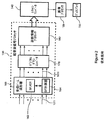
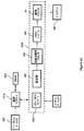
図1は、従来技術による典型的な医療用超音波システムの一例を示すブロック図である。送信ビーム成形器104は、デジタル又はアナログビーム成形器のような既知の構造のものである。送信ビーム成形器104は、システムコントローラ102に応答して1つ以上の励起信号を発生する。励起信号は、典型的に、1ないし20MHz範囲の関連中心周波数を有する。送信ビーム成形器104からの励起信号は、送信/受信スイッチ112を経て超音波トランスジューサ110に与えられる。超音波トランスジューサ110は、トランスジューサ素子110iのアレイを含む。超音波トランスジューサ110は、検査を受ける対象者に超音波を結合できるようにする既知の構造のものである。トランスジューサ素子110iは、超音波の発射及び受信の両方を行う。送信/受信スイッチ112は、送信及び受信モードのためのスイッチング回路を含む。送信モードでは、送信/受信スイッチ112は、送信ビーム成形器104からの励起信号をトランスジューサ110へ結合する。受信モードでは、送信/受信スイッチ112は、トランスジューサ110から受信した超音波信号をアナログフロントエンド(AFE)114へ結合する。送信の場合に、トランスジューサ素子110iは、励起信号を変換して、超音波音響波形を発生する。特に、トランスジューサ110は、送信ビーム成形器104に応答して、励起信号を、対象者内をある方向に進行する超音波波形へ変換する。異なる音響インピーダンスを伴う界面を有する散乱場所で超音波波形を反射させて、トランスジューサ110へエコーを返送させる。複数のトランスジューサ素子110iがエコーを受信して、複数のアナログ超音波信号へと変換する。送信/受信スイッチ112は、トランスジューサ110からの複数のアナログ超音波信号をサンプリング窓間にAFE114へ結合する。サンプリング窓は、受信したエコーが対象者の望ましい深さ範囲内の散乱場所からの反射を表すところの時間インターバルに対応する。コントローラ102は、ユーザ入力又はスキャンプロトコルに従ってサンプリング窓をセットし、そして送信/受信スイッチ112にタイミングコントロール情報を与える。送信/受信スイッチ112は、サンプリング窓間に複数のアナログ超音波信号を並列に出力する。AFE114は、アナログ/デジタル変換のための準備として複数のアナログ超音波信号を増幅しそしてフィルタリングする。AFE114は、各アナログ信号チャンネル113iに対して、低ノイズ増幅器(LNA)、可変利得増幅器(VGA)及びローパスフィルタを含むことができる。VGAは、受信信号強度が時間と共に減少するので、時間の関数として利得を増加する利得プロフィールを適用する。時間に伴う信号強度の低下は、超音波がより多くの組織を通してより長い距離進行するにつれて減衰することから生じる。ADCバンク120は、サンプリング窓の間に受信した複数のアナログ超音波信号を、並列の超音波信号サンプルの複数のシーケンスへ変換するための複数のADCを備えている。各ADC入力チャンネル115iにおけるアナログ超音波信号は、それに対応するADC出力チャンネル121iにおける超音波信号サンプルのストリームへと変換される。超音波信号サンプルは、トランスジューサの圧電材料の固有の共振周波数に関連した受信超音波信号の高周波(RF)に典型的に対応する非ゼロの中心周波数を有する。
FIG. 1 is a block diagram illustrating an example of a typical medical ultrasound system according to the prior art. The transmit
超音波信号プロセッサ130は、ビーム成形、ダウン変換、Bモード処理、及び/又はドップラー処理を含めて、超音波信号サンプルから診断情報を抽出するオペレーションを遂行し、これについては図2を参照して更に説明する。超音波信号プロセッサ130は、デジタル信号プロセッサ(DSP)、フィールドプログラマブルゲートアレイ(FPGA)、マイクロプロセッサ、又はコンピュータのCPUのような1つ以上のプロセッサで具現化することができる。スキャンコンバータ140は、処理されたサンプルのフレームの座標変換を遂行して、ラスタ(直線)フォーマットを有する超音波画像サンプルのフレームを発生する。画像プロセッサ150は、付加的な画像向上オペレーションを超音波画像サンプルに適用することができる。ディスプレイ160は、ユーザにより分析するための2次元又は3次元画像を与える。
The
図2は、従来技術による超音波信号プロセッサ130のブロック図である。医療用超音波システムは、ADCバンク120から出力されたRF超音波信号サンプルに対してデジタルビーム成形オペレーションを遂行することができる。受信ビーム成形器160は、遅延、アポダイゼーション(減衰)及び加算オペレーションを超音波信号サンプルに適用して、視野内の特定の方向に対応するビーム成形サンプル又はビームの1Dアレイを形成する。受信ビーム成形器160は、視野内の多数の方向に対応するビーム成形サンプルの多数の1Dアレイを発生する。受信ビーム成形器160は、表示のための超音波信号サンプル及びビーム成形(BF)計算器164の加算オペレーションを記憶するためにビーム成形器(BF)メモリ162を備えている。BF計算器164は、同じ受信パルスに対してBFメモリ162から検索された超音波信号サンプルを使用して複数のビームを成形することができる。又、BF計算器164は、補間を隣接超音波信号サンプルに適用して、計算されるビームの位相解像度を改善することができる。又、受信ビーム成形器160は、加算オペレーションの前にサンプルに重み付け関数を適用して、空間的窓機能又はアポダイゼーションを具現化することができる。各角度に対して計算されたビーム成形サンプルは、それに対応するビーム成形器出力チャンネル161iに与えられる。受信ビーム成形器160は、典型的に、ADC出力チャンネル121iより成る入力チャンネルより少ない出力チャンネル161iを有する。この構成では、ビーム成形サンプルは、RF中心周波数を有する。デジタルダウンコンバータ(DDC)170は、ビーム成形サンプルを基本帯域へと復調し、各ビームに対する複雑な基本帯域I及びQサンプルを発生する。DDC170とは別に又はそれに加えて、希望の周波数を中心とする周波数帯域でビーム成形サンプルにバンドパスフィルタを適用することもできるし、又はDDC170がビーム成形サンプルを基本帯域ではなくて中間周波(IF)へ復調することもできる。この技術の別のアーキテクチャーは、アナログ/デジタル変換の前にアナログビーム成形を行い、そしてビーム成形の前に超音波信号サンプルのデジタルダウン変換を行うことを含む。
FIG. 2 is a block diagram of an
診断情報プロセッサ180は、希望のタイプの超音波画像のためにI、Qサンプルに対して適当なオペレーションを遂行する。Bモード処理は、エコー信号の強度を表す情報を発生する。I、Qサンプルの大きさは、Bモード画像のための検出サンプルを形成するように計算することができる。ドップラー処理は、I、Qサンプルから速度、速度の偏差、及びエネルギーを推定して、ドップラー検出サンプルを形成する。Bモード検出サンプル及びドップラー検出サンプルの空間的座標は、ビーム成形サンプルの幾何学形状に対応する。スキャンコンバータ140は、検出サンプルの座標変換を遂行して、表示に適したラスタフォーマットを有するデータのフレームを発生する。画像プロセッサ150は、サンプルのフレームの付加的な画像処理を、表示の前に、2次元又は3次元画像として遂行する。
The
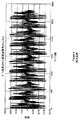
図3は、ビーム成形の前の超音波信号サンプルのプロットである。このプロットは、ADCアレイの1つのADCによってサンプリングされた4つのパルスエコーに対する同相サンプルを表示するものである。この例では、ビーム成形の前に、ADCから出力された超音波信号サンプルにデジタルダウン変換が適用されて、I、Qサンプルを形成している。図4は、1つのビーム成形出力チャンネルに対応するビーム成形超音波信号の同相サンプルのプロットである。この例では、ビーム成形器は、遅延及び重み付け関数をI、Qサンプルに適用することにより複数のADCから出力されたI、Qサンプルの複数のシーケンスを合成する。 FIG. 3 is a plot of ultrasound signal samples prior to beam shaping. This plot displays in-phase samples for four pulse echoes sampled by one ADC of the ADC array. In this example, before beam shaping, digital down conversion is applied to the ultrasonic signal samples output from the ADC to form I and Q samples. FIG. 4 is a plot of in-phase samples of the beam-shaping ultrasound signal corresponding to one beam-shaping output channel. In this example, the beam shaper combines a plurality of sequences of I and Q samples output from a plurality of ADCs by applying a delay and weighting function to the I and Q samples.
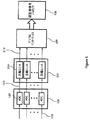
図5は、好ましい実施形態により、ADC120のバンクから出力される超音波信号サンプルを圧縮することを含む超音波システムのブロック図である。圧縮器210は、複数の圧縮ユニット210iを備えている。複数の圧縮ユニット210iは、各トランスジューサ素子(例えば、図1の110i)から出力されるアナログ超音波信号を表す信号サンプルの複数のシーケンスを圧縮して、圧縮サンプルの複数のシーケンスを圧縮器出力211iに形成する。圧縮ユニット210iは、サンプリング窓の間に対応トランスジューサ素子110iから出力されるアナログ超音波信号を表す対応ADC120iのADC出力121iからの信号サンプルのシーケンスを受信し、ここで、サンプリング窓は、アナログ超音波信号が、対象物の対応深さ範囲から反射されるエコーを表すところの時間インターバルである。圧縮ユニット210iは、その入力における信号サンプルの特定のシーケンスに、同じサンプリング窓の間に他のトランスジューサ素子から出力されるアナログ超音波信号を表す信号サンプルとは独立して圧縮オペレーションを適用して、圧縮サンプルの対応シーケンスを圧縮器出力211iに発生する。或いは又、圧縮ユニット210iは、2つ以上のADCからのサンプルを圧縮してもよく、この場合、特定のADC120iからの信号サンプルは、同じサンプリング窓の間に他のトランスジューサ素子から出力されるアナログ超音波信号を表す信号サンプルとは独立して圧縮される。ここでの説明は、各ADC120iが実数値サンプルのシーケンスを発生することを仮定している。或いは又、ADC120iが直角位相サンプリングを遂行して、I及びQサンプルのシーケンスを各ADC出力121iに発生する場合には、I、Qサンプルの各シーケンスが独立して圧縮される。圧縮は、ビーム成形の前に、超音波信号サンプルに適用される。圧縮されたサンプルは、デジタルインターフェイス220を横切って超音波信号プロセッサ130へ転送され、そこで、超音波処理オペレーションのために解凍される。圧縮サンプルを転送するためにデジタルインターフェイス220に必要とされるデータ転送帯域巾は、非圧縮の超音波信号サンプルのストリームを転送するための帯域巾に比して減少される。
FIG. 5 is a block diagram of an ultrasound system that includes compressing ultrasound signal samples output from a bank of
図6は、別の構成により超音波信号サンプルを圧縮しそしてその圧縮したサンプルをキャプチャーメモリに記憶することを含む超音波システムのブロック図である。デジタルインターフェイス220を横切って転送された後に、圧縮サンプルは、キャプチャーメモリ230に記憶される。圧縮サンプルを記憶するのに充分なキャプチャーメモリ230の容量が減少され、従って、システムリソースが保存される。解凍器240は、キャプチャーメモリから検索された圧縮サンプルを解凍する。受信ビーム成形器160は、解凍されたサンプルにビーム成形オペレーションを適用して、ビーム成形されたサンプルのシーケンスを各ビーム成形出力チャンネル161iに形成する。図2を参照して述べたように、解凍されたサンプルには、ビーム成形オペレーションの前に、デジタルダウン変換及び/又はフィルタリングを適用することができる。
FIG. 6 is a block diagram of an ultrasound system that includes compressing ultrasound signal samples according to another configuration and storing the compressed samples in a capture memory. After being transferred across the
図7は、別の構成により圧縮サンプルがビーム成形器メモリに記憶される超音波システムのブロック図である。受信ビーム成形器160は、ビーム成形器(BF)メモリ162に圧縮サンプルを記憶し、そしてビーム成形オペレーションのために必要に応じて圧縮サンプルを検索する。解凍器240は、BFメモリから検索された圧縮サンプルを処理し、そして解凍したサンプルをBF計算器164に与える。BF計算器164は、ビーム成形オペレーションを解凍サンプルに適用する。又、BF計算器164は、図2を参照して述べたように、空間的フィルタリングのために解凍サンプルに対して付加的なオペレーションを遂行することもできる。
FIG. 7 is a block diagram of an ultrasound system in which compressed samples are stored in beam shaper memory according to another configuration. The receive beamformer 160 stores the compressed samples in a beamformer (BF)
圧縮サンプルは、サンプル当たりのビットが元の超音波信号サンプルより少ないので、圧縮サンプルは、非圧縮サンプルより少数のデータポートを使用してデジタルインターフェイス220を横切って転送することができる。図8は、圧縮サンプルを、少数のデータポートを横切って転送するためにマルチプレクスすることを含む超音波システムのブロック図である。この例では、ADCバンク120は、N個のADC120i、ADC1からADCNを含み、N個のADC出力チャンネル120i、X1からXNに信号サンプルのストリームを発生する。圧縮ユニット210iは、N個の圧縮器出力211i、Y1からYNに圧縮サンプルの対応ストリームを発生する。圧縮サンプルは、減少ビットレートを有し、データポート270iに与えられる。好ましくは、データポート270iは、低電圧の差動シグナリング(LVDS)データ送信を与える。或いは又、データポート270iは、データ送信のためにシリアライザ/デシリアライザ(SerDes)インターフェイスを使用することもできる。ナショナルセミコンダクタ社により2008年1月に出版された“LVDS Owner’s Manual Including High-Speed CML and Signal Conditioning”と題する文書、第4版には、LVDS装置及びアーキテクチャーが記述されている。LVDSデータ送信は、3.125Gbpsの最大データ転送レート、低ノイズ及び低電力消費を含む望ましい特性を有する。差動シグナリングは、正の差動出力について1つ及び負の差動出力について1つの、2つのI/Oピンをチャンネル出力当たりに要求し、これは、LVDS対と称される。データポート270iは、圧縮器出力Yiにおける圧縮サンプルのビットレートがポートの最大データ転送レートより低いときには、過剰な帯域巾を有する。この過剰な帯域巾は、所与のデータポート270iを経て転送するために圧縮サンプルの複数のストリームを合成することにより利用することができる。マルチプレクサ250は、M<Nとすれば、圧縮サンプルのN個のシーケンスを合成して、M個のデータポート270iを経て転送するためのマルチプレクスされた圧縮サンプルのM個のシーケンスを形成する。合成することのできる圧縮サンプルストリームの数は、データ転送ポート270iの帯域巾により制限される。例えば、N=16 ADCで、各ADCが、50メガサンプル/秒(Msps)のサンプルレートにおいてサンプル当たり12ビットで超音波信号サンプルを発生する場合に、各ADC出力チャンネル121iのビットレートは、600Mbpsとなる。データポート270iは、データ転送レートが800Mbpsまでであり、そして圧縮器210は、3:1の圧縮比を発生すると仮定する。圧縮器出力121iにおける圧縮サンプルシーケンスYiは、ビットレートが200Mbpsである。このケースでは、1つのデータポート270iは、4つの圧縮器出力から800Mbpsのデータ転送レートで圧縮サンプルを転送するのに充分な帯域巾を有する。この例では、マルチプレクサ250は、4つの圧縮シーケンスYi、Yi+1、Yi+2及びYi+3のグループからの圧縮サンプルを合成して、マルチプレクスされた圧縮サンプルZjの対応シーケンスを1つのマルチプレクサ出力251iに形成する。この例では、マルチプレクスされた圧縮サンプルのシーケンス及びそれに対応するアクティブなデータポートの数は、M=N/4=4である。シリアライザ260は、ビットのシーケンスを対応データポート270iに与える。
Because compressed samples have fewer bits per sample than the original ultrasound signal samples, compressed samples can be transferred across
圧縮サンプルをマルチプレクスしてM個のデータポートを使用する効果は、より少数の物理的データポートを使用することを含み、これは、次いで、データポートの接続及び電力消費を減少する。圧縮サンプルのビットレートが固定である用途では、マルチプレクサ250は、固定数の物理的データポート270iに対して固定数のマルチプレクサ出力251iを有する。或いは又、融通性のあるアーキテクチャーは、圧縮サンプルのビットレートに基づいて可変数のアクティブなデータポートをサポートすることができる。融通性のあるアーキテクチャーでは、圧縮器210は、ユーザ選択可能な圧縮比パラメータに基づく種々のビットレートで圧縮サンプルを与える。圧縮コントローラ(図8には示されていない)は、オペレーションが希望の圧縮比に対応するビットレートで圧縮サンプルを発生するように、圧縮コントロールパラメータを圧縮ユニット210iに与える。圧縮コントローラは、マルチプレクサ出力251iに発生すべきマルチプレクスされた圧縮サンプルのシーケンスの数を指示するためにマルチプレクスコントロールパラメータをマルチプレクサ250に与える。又、圧縮コントローラは、ユーザ入力に応答して、インアクティブなデータポートを電源オフにし、電力を更に保存することができる。
The effect of multiplexing the compressed samples to use M data ports includes using fewer physical data ports, which in turn reduces data port connectivity and power consumption. For applications where the bit rate of the compressed samples is fixed, the
又、データポート270iが、信号サンプルを圧縮しなくても、サンプルレート及びビット/サンプルのある値に対して過剰な帯域巾をもつことも考えられる。データポート270iは、サンプルレートとビット/サンプルの数値との積が、データポート270iの最大データ転送レートより低いビットレートをADC出力121iに生じるときに、過剰帯域巾を有する。例えば、ADCのクロック周波数が、50Mspsに対応する50メガヘルツ(MHz)であり、そしてサンプル巾が12ビット/サンプルであって、各ADC120iが600メガビット/秒(Mbps)を発生すると仮定する。データ転送レートは、各データポート270iに対して600Mbpsとなる。800Mbpsの最大データ転送レートを有するLVDSポートでは、各ポートに対して200Mbpsの未使用帯域巾がある。データポート270iは、LVDSインターフェイスが一定電流(従って、一定電力)リンクであるから、600Mbpsでデータを転送するのに、800Mbpsの全容量でデータを転送する場合と同じ量の電力を消費する。ポートコンセントレーションは、複数のADC出力からのビットを合成しそしてその合成したデータを、より少数のポートを経てより速いレートで送信することにより、過剰なデータ転送容量を利用する。各データポートは、その合成データを、ADCビットレートより高く且つ各データポート270iレートの最大データ転送レートまでのレートで送信する。
It is also conceivable that the
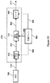
図9は、ADC出力121iにポートコンセントレーションを適用する超音波システムのブロック図である。N個のADC出力X1からXNにおける超音波信号サンプルのN個のシーケンスがマルチプレクサ252へ入力される。マルチプレクサ252は、M<Nとすれば、ADC出力のグループからのサンプルを合成して、マルチプレクスされた信号サンプルR1からRMのM個のチャンネルを形成する。各チャンネルRiは、そのビットレートが、ADC出力121iにおけるADCビットレートより高いが、データポート270iの最大データ転送レート(ビット/秒)以下である。マルチプレクサ250は、各サンプル周期に対するN個の信号サンプルのビットをM個のビットサブセットへとマップすることによりサンプルを合成する。シリアライザ262は、対応するデータポート270iにより転送するためのビットのサブセットの各々をシリアル化する。更に、ADCの数Nが16である前記例について考える。600MbpsのADCビットレートで16個のADC120iから出力される信号サンプルは、各々800Mbpsのビットレートの12ビットストリームへと合成することができる。12個のアクティブなデータポート270iは、12ビットストリームを各々800Mbpsのデータ転送レート(800Mbpsx12=600Mbpsx16)で転送する。サンプルレート、ビット/サンプルの数値、及び最大データ転送レートに基づいて、多数の構成が考えられる。
FIG. 9 is a block diagram of an ultrasound system that applies port concentration to the
図10Aは、16個のADCからデータを転送するために12個のデータポートを含むポートコンセントレーション構成のブロック図である。この構成は、50MHzまでのADCクロック周波数に対応する50Mspsまでのサンプルレートを受け入れることができる。ADC入力クロック118は、周波数がADCサンプルレートに対応するクロック信号を搬送する。ADC120は、ADC入力クロック118に応答して、入力アナログ信号をサンプルレートでサンプリングする。マルチプレクサ252は、ADCのバンク120から出力される信号サンプルを受け取る。4つのADC120h、120i、120j及び120kは、1つのマルチプレクサ252iに信号サンプルを与える。マルチプレクサ252iは、3つの出力253i、253j及び253kを含む。マルチプレクサ252iは、各サンプル周期中にそれが受信したサンプルの48ビットを再順序付けし、そしてその再順序付けしたビットを3つのシリアライザ261i、262j及び262kに分配する。各シリアライザ261i、262j及び262kは、48の再順序付けされたビット、この場合は、16ビットのサブセットを受け取り、そして対応するポート270i、270j及び270kにより転送するためのそれをシリアル化する。位相固定ループ(PLL)280は、ADCクロック周波数の16倍の周波数を有するデータクロック281を発生する。PLL280は、ADC入力クロックに対して動作して、シリアライザ262及びデータポート270のためのデータクロック281を発生する。データクロック周波数は、各シリアライザ262iから出力されるビットのデータ転送レートに対応する。データクロック周波数は、ADCクロック周波数に、サンプル周期当たりのマルチプレクスされたビット数を乗算したものである。12のデータポート270は、シリアル化されたビットを、サンプルレートの16倍のデータ転送レートで転送する。
FIG. 10A is a block diagram of a port concentration configuration that includes 12 data ports to transfer data from 16 ADCs. This configuration can accept sample rates up to 50 Msps, corresponding to ADC clock frequencies up to 50 MHz. The
図10Bは、図10Aの構成に対して1つのサンプル周期中にデータポート270に与えられるビットの配列を示す。テーブル290は、1つのサンプル周期中に16個のADCから出力されるサンプルビットのビットマッピングを示す。4つのマルチプレクサ252及び3つのシリアライザ262を有する構成では、マルチプレクサ252は、各信号サンプルのビットを4ビットのブロックへとグループ編成する。マルチプレクサ252iは、ビットの第1ブロックをシリアライザ262iへ向け、ビットの第2ブロックをシリアライザ262jへ向け、そしてビットの第3ブロックをシリアライザ262kへ向ける。行290i、290j及び290kは、各々、シリアライザ262i、262j及び262kのビットマッピングを表す。各シリアライザ262が1つのサンプル周期中に16個のマップされたビットを出力するならば、異なるビット順序を生じる他のビットマッピングを使用することもできる。デジタルインターフェイス220を横切って転送された後、受信されマルチプレクスされたビットは、信号サンプルの元のシーケンスを回復するために、逆のビットマッピングに基づいて再順序付けされる。
FIG. 10B shows the arrangement of bits provided to
図11は、信号サンプルの元のシーケンスを回復するためにポートコンセントレーションから生じる受信されマルチプレクスされたビットストリームを再順序付けするブロック図である。ポートコンセントレーションモードにおいて、受信器は、より少数の入力データポート310を必要とするだけであり、電力節約及び複雑さの減少となる。入力データポート310は、LVDS受信器である。各LVDS受信器は、LVDS送信により発生される差動信号を受信し、そしてそれに対応する受信ビットを再生するロジック状態を発生する。デシリアライザ315は、受信されたシリアルビットを、マルチプレクスされた信号サンプルRからRのM個のパラレルチャンネルへ変換する。デマルチプレクサ320は、マルチプレクスされた信号サンプルのビットを、信号サンプルの元のシーケンスX1からXNの順序へ再アレンジする。次いで、超音波信号プロセッサ130は、信号サンプルの再生されたシーケンスにビーム成形又はデジタルダウン変換のようなオペレーションを適用する。‘988特許出願には、ポートコンセントレーションモードに対する付加的な別の形態が述べられている。
FIG. 11 is a block diagram of reordering the received multiplexed bitstream resulting from port concentration to recover the original sequence of signal samples. In port concentration mode, the receiver only requires fewer
圧縮ユニット210iにより適用される圧縮方法は、ブロックフローティングポイントエンコーディングを行い、そして信号サンプルの第1又はそれより高次の導関数を計算し、それに続いて、ブロックフローティングポイントエンコーディングを行うことを含む。ブロックフローティングポイントエンコーディングに代わって、ハフマン又は他の形式のエンコーディングを行うこともできる。 The compression method applied by compression unit 210i includes performing block floating point encoding and calculating a first or higher order derivative of the signal sample followed by performing block floating point encoding. Instead of block floating point encoding, Huffman or other forms of encoding can also be performed.
圧縮ユニット210iの好ましい実施形態は、ADC出力121iからの連続的信号サンプルのグループにブロックフローティングポイントエンコーディングを適用し、各グループは、N_GROUPサンプルを有する。N_GROUPサンプルの最大指数がエンコードされ、そしてN_GROUPサンプルが次の段階に基づいてエンコードされる。
N_GROUPサンプルの第1グループの場合:
1)最大の大きさをもつサンプルの指数(底2)を、例えば、N_GROUPサンプルの各グループにおいて最大の大きさのlog2を計算することにより決定する。これは、エンコードされたサンプル当たりのビット数、又はn_exp(0)を指示する。
2)S個のビットを使用して第1グループの指数n_exp(0)を絶対エンコードする。ここで、Sは、サンプル当たりの元のビット数である。
3)サンプル当たりn_exp(0)ビットを使用してN_GROUPサンプルをエンコードする。
N_GROUPサンプルのi番目のグループの場合(i>0):
4)最大の大きさをもつサンプルのi番目の指数(底2)を決定する。これは、i番目のグループにおけるエンコードされたサンプル当たりのビット数、又はn_exp(i)を指示する。
5)n_exp(i−1)からn_exp(i)を減算することによりi番目の指数を差動エンコードし、i番目の差の値を決定する。対応するトークンを使用してi番目の差の値をエンコードする。但し、短いトークンは、共通性の多い差の値を表し、そして長いトークンは、共通性の少ない差の値を表す。
6)サンプル当たりn_exp(i)を使用してN_GROUPサンプルのi番目のグループをエンコードする。
A preferred embodiment of the compression unit 210i applies block floating point encoding to groups of consecutive signal samples from the
For the first group of N_GROUP samples:
1) Determine the index (base 2) of the sample with the largest size, for example by calculating the largest size log 2 in each group of N_GROUP samples. This indicates the number of bits per encoded sample, or n_exp (0).
2) Absolutely encode the first group of exponents n_exp (0) using S bits. Here, S is the original number of bits per sample.
3) Encode N_GROUP samples using n_exp (0) bits per sample.
For i-th group of N_GROUP samples (i> 0):
4) Determine the i-th index (base 2) of the sample with the largest size. This indicates the number of bits per sample encoded in the i th group, or n_exp (i).
5) Subtract n_exp (i) from n_exp (i-1) to differentially encode the i-th exponent and determine the i-th difference value. Encode the i th difference value using the corresponding token. However, a short token represents a difference value with a high commonality, and a long token represents a difference value with a low commonality.
6) Encode the i th group of N_GROUP samples using n_exp (i) per sample.
第1のサンプルグループの場合に、指数n_exp(0)が直接エンコードされる。例えば、指数n_exp(0)は、次のようにエンコードすることができる。但し、Sは、サンプル当たりの元のビット数である。
a.0: n_exp(0)=0(4つのサンプル値は全てゼロ)
b.1: n_exp(0)=2(サンプル当たり2ビット)
c.2: n_exp(0)=3(サンプル当たり3ビット)
d.等、S−1まで: n_exp(0)=S(サンプル当たりSビット)
For the first sample group, the index n_exp (0) is directly encoded. For example, the index n_exp (0) can be encoded as follows. Where S is the original number of bits per sample.
a. 0: n_exp (0) = 0 (all four sample values are zero)
b. 1: n_exp (0) = 2 (2 bits per sample)
c. 2: n_exp (0) = 3 (3 bits per sample)
d. Etc., up to S-1: n_exp (0) = S (S bits per sample)
i番目のグループの場合に、指数n_exp(i)は、プレフィックスコードを使用して差動エンコードされ、但し、別のコードワードのプレフィックスとなるコードワードはない。好ましい差動エンコーディングは、次の通りである。
1.差を計算する:e_diff=n_exp(i)−n_exp(i−1)
2.e_diffを次のようにエンコードする:
a.0: e_diff=e(i)−e(i−1)
b.101: e_diff=+1
c.110: e_diff=−1
d.1001: e_diff=+2
e.1110: e_diff=−2
f.等
或いは又、指数n_exp(i)は、差動エンコードされるのではなく、ハフマンエンコードされてもよい。
For the i th group, the index n_exp (i) is differentially encoded using a prefix code, but there is no codeword that is a prefix of another codeword. A preferred differential encoding is as follows.
1. Calculate the difference: e_diff = n_exp (i) −n_exp (i−1)
2. Encode e_diff as follows:
a. 0: e_diff = e (i) −e (i−1)
b. 101: e_diff = + 1
c. 110: e_diff = −1
d. 1001: e_diff = + 2
e. 1110: e_diff = -2
f. Alternatively, the index n_exp (i) may be Huffman encoded rather than differentially encoded.
図12は、N_GROUP=4であるブロックフローティングポイントエンコーダのブロック図である。指数計算器402は、ステップ1及びステップ4のように、N_GROUPサンプルに対し、最大指数n_expをビットで決定する。指数トークンジェネレータ404は、ステップ2及びステップ5のように、n_exp値をエンコードする。仮数パッカー406は、ステップ3及びステップ6のように、N_GROUPサンプルに対する仮数をエンコードする。図13は、エンコーディングのための信号サンプルのn_bitを選択する一例を示す。入力信号サンプル420は、Kビットで表される。サンプル420のn_exp下位ビットは、エンコーディングに対して選択される。選択されたビットにサンプルの符号ビットが添付され、それにより得られるビットシーケンスが仮数を表す。図12に戻ると、マルチプレクサ408は、エンコードされた指数トークン411及びそれに続くN_GROUP仮数をパックし、N_GROUP圧縮サンプルを表す圧縮グループ410を形成する。この例では、圧縮グループ410は、指数トークン411及びそれに続く4つのパックされた仮数のシーケンス412−0、412−1、412−2及び412−3を含む。圧縮ユニット210iは、連続する圧縮グループを連結して、圧縮器出力211iに圧縮パケットのデータ部分を形成する。N_GROUPの好ましいサイズは、グループ当たり3又は4個のサンプルである。しかしながら、可変グループサイズも使用できる。
FIG. 12 is a block diagram of a block floating point encoder with N_GROUP = 4. The
仮数及び指数を別々にエンコードすることで、付加的な圧縮を与え、そして圧縮エラーを軽減することができる。連続する指数の差の値が計算され、エンコードされる。指数はゆっくり変化し、従って、比較的僅かな非ゼロ値が、ゼロ値のストリングにより分離される。指数の差の値は、非ゼロの差の値及びそれに対応する位置だけを表すことにより効率的にエンコードすることができる。位置は、それに対応するインデックス値により、又は最後の非ゼロの差の値の位置に対して、表すことができる。指数の差の値のエンコーディングは、ロスレスであり、比較的大きなエラーを防止する。指数のデコーディングについては、指数値は、指数の差の値を積分しそしてそれに対応する位置場所をデコードすることにより再構成される。仮数のデコーディングについては、再構成された各仮数値は、デコードされたサンプルの対応する指数の値を変化させないように制限される。n_expのデコードされた指数については、再構成された仮数は、2n_exp−1の最大値をもつことができる。これは、仮数の圧縮エラーが指数の値を変化させるのを防止する。 Encoding the mantissa and exponent separately can provide additional compression and reduce compression errors. Successive exponent difference values are calculated and encoded. The exponent changes slowly, so that relatively few non-zero values are separated by a string of zero values. Exponential difference values can be efficiently encoded by representing only non-zero difference values and their corresponding positions. The position can be represented by its corresponding index value or relative to the position of the last non-zero difference value. The encoding of the exponent difference value is lossless and prevents relatively large errors. For exponent decoding, the exponent value is reconstructed by integrating the exponent difference value and decoding the corresponding location. For mantissa decoding, each reconstructed mantissa is constrained to not change the value of the corresponding exponent of the decoded sample. For a decoded exponent of n_exp, the reconstructed mantissa can have a maximum value of 2 n_exp −1. This prevents mantissa compression errors from changing the value of the exponent.
別のブロックフローティングポイントエンコーディング方法は、仮数を表すビットの数を減少しそして上述したように指数を差動エンコーディングすることを含む。N_GROUPサンプルの仮数を表すビットの数は、グループに対するn_expの値に基づいて、各仮数から最下位ビット(LSB)の数を選択的に除去することにより減少される。図14は、減少された仮数を表すためのビットを選択する一例を示す。n_expは、上述したステップ1及びステップ4のように決定される。仮数のn_exp下位ビットを全てエンコーディングするのではなく、最下位ビットでスタートしてビット数n_LSBが除去される。残りのm_expビット(m_exp=n_exp−n_LSB)がエンコーディングのために選択される。n_LSBの値は、式又はテーブルに基づきn_expの値に依存する。図15は、n_exp、n_LSB及びm_expの規範的な値を示すテーブルである。n_expのより大きな値について、m_expビットを有する減少された仮数を形成するように切断又は丸めることにより、より多くのLSBが除去される。例えば、n_expが12である場合には、3つのLSBが除去され、N_GROUPの減少された仮数をパッキングするために9つの仮数ビットが保持される。圧縮器210は、n_exp、n_LSB及びm_expの値のルックアップテーブルを記憶することができる。或いは又、圧縮器210は、n_LSB及びm_expをn_expの関数として表し、そして必要に応じてそれらの値を計算することができる。図16は、減少された仮数を使用するブロックフローティングポイントエンコーディングのブロック図である。N_GROUPサンプルの各グループに対して、指数計算器402は、上述したように、最大指数n_expを決定する。仮数ビット計算器414は、ルックアップテーブル又は式を使用して減少された仮数におけるビットの数m_expを決定する。減少された仮数のパッカー416は、N_GROUPサンプルの各々に対してm_expビットを選択する。次いで、マルチプレクサ408は、指数トークン411及びそれに続く減少された仮数419−0、419−1、419−2及び419−3をパックして、圧縮グループ418を形成する。ある条件については、N_GROUPサンプルのグループから除去されるLSBはない。例えば、N_GROUPサンプルにおける1つ以上のサンプルの大きさが許容最小値より小さいときには、元のLSBを含むN_GROUP仮数がパックされる。圧縮サンプルのシーケンスは、減少された仮数を伴ったり伴わなかったりする圧縮グループを含むことができる。
Another block floating point encoding method includes reducing the number of bits representing the mantissa and differential encoding the exponent as described above. The number of bits representing the mantissa of the N_GROUP sample is reduced by selectively removing the least significant bit (LSB) number from each mantissa based on the value of n_exp for the group. FIG. 14 shows an example of selecting bits to represent the reduced mantissa. n_exp is determined as in
圧縮コントローラは、ブロックフローティングポイントエンコーディングに対して圧縮ユニット210iに圧縮コントロールパラメータを与える。n_LSB、m_exp及びn_expのための複数の別のルックアップテーブル又は式がある。圧縮コントロールパラメータは、n_LSB、m_exp及びn_expのための別のルックアップテーブル又は式に対してN_GROUP及び選択パラメータを含む。圧縮コントロールパラメータは、全ての圧縮ユニット210iに対して均一である。或いは又、圧縮コントロールパラメータは、異なる圧縮ユニット210iに対して異なる値をもつことができる。圧縮コントローラは、ユーザ入力に応答して、圧縮コントロールパラメータを選択することができる。 The compression controller provides compression control parameters to the compression unit 210i for block floating point encoding. There are a number of different lookup tables or expressions for n_LSB, m_exp and n_exp. The compression control parameters include N_GROUP and selection parameters for another lookup table or expression for n_LSB, m_exp, and n_exp. The compression control parameters are uniform for all compression units 210i. Alternatively, the compression control parameters can have different values for different compression units 210i. The compression controller can select compression control parameters in response to user input.
圧縮されたサンプルは、デジタルインターフェイス220を経て転送するために圧縮パケットのデータ部分へ挿入することができる。ADC120iによってデジタル化された受信パルスに対応する圧縮サンプルのシーケンスは、1つ以上の圧縮パケットに配列することができる。或いは又、図9を参照して述べたように、複数のADC120iからの圧縮サンプルのシーケンスを合成して、所与のデータポート270iを経て転送するための圧縮パケットを形成することもできる。圧縮パケットのヘッダ部分は、パケットのための識別情報を含む。又、ヘッダは、パケットにおける圧縮されたサンプルの圧縮コントロールパラメータを表すコントロールデータも含むことができる。圧縮コントロールパラメータに関する情報は、解凍オペレーションを構成するように解凍器240により使用することができる。
The compressed samples can be inserted into the data portion of the compressed packet for transfer via the
解凍については、解凍器240は、圧縮サンプルのシーケンスにブロックフローティングポイントデコーディングを適用する。N_GROUP圧縮サンプルの各グループについては、解凍器240は、指数トークンをデコードして、n_expの値を決定する。差動エンコードされた指数は、積分されて、n_expの値を形成する。次いで、圧縮グループ410又は418からの各仮数に対するビットをアンパックして、それらビットを解凍ビットへとマッピングすることにより、N_GROUP仮数が再構成される。解凍されたサンプルは、超音波信号プロセッサ130のダウンストリーム処理要求に基づいてサンプル当たりの元のビット数又はサンプル当たりの異なるビット数により表すことができる。減少仮数を使用するブロックフローティングポイントエンコーディングについては、解凍器240は、n_expのデコード値に基づいてn_LSBの値を決定するためのルックアップテーブル又は式も含む。減少仮数に対するアンパックされたビットには、元のサンプルを近似するためにゼロ又はディザ値であるn_LSBビットが添付される。
For decompression,
‘533特許は、ある帯域制限信号を圧縮及び解凍するためのアルゴリズムについて述べている。以下に述べる別の圧縮方法の幾つかは、超音波信号サンプルに関する‘533特許のアルゴリズムの変更である。 The '533 patent describes an algorithm for compressing and decompressing certain band limited signals. Some of the other compression methods described below are modifications to the '533 patent algorithm for ultrasound signal samples.
超音波信号サンプルを圧縮するための別の態様は、差を計算した後に、エンコードすることである。超音波信号サンプルの第1又はそれより高次の差を計算することで、元の信号サンプルより大きさが小さい差のサンプルを得ることができる。差のサンプルをエンコードすることにより、サンプルそれ自体をエンコードする場合より大きな圧縮を得ることができる。ADC出力121iの連続サンプルの差を計算するのに続いて、上述したように、差のサンプルのブロックフローティングポイントエンコーディングを行うことができる。この場合は、差のサンプルが、ADC出力121iの信号サンプルではなく、ブロックフローティングポイントエンコーダに入力される。或いは又、ハフマンエンコーディング又は他のエンコーディングを差のサンプルに適用することができる。
Another aspect for compressing the ultrasound signal sample is to encode after calculating the difference. By calculating the first or higher order difference of the ultrasound signal samples, a difference sample having a smaller magnitude than the original signal sample can be obtained. By encoding the difference sample, a greater compression can be obtained than when the sample itself is encoded. Subsequent to calculating the difference between successive samples of the
図17は、差の演算を含む圧縮ユニット210iのブロック図である。圧縮ユニット210iは、ADC120iから超音波信号サンプルを受け取る。圧縮コントローラ340は、各圧縮ユニット210iの差の演算器330i及びエンコーダ332iに対する圧縮コントロールパラメータを与える。差の演算器330iの圧縮コントロールパラメータは、第1、第2又はそれより高次の差を選択することができる。差の演算器330iは、選択された差の順序を適用して、差のサンプルを発生する。又、圧縮コントロールパラメータは、エンコーダ332iが差のサンプルではなく信号サンプルをエンコードするように、差の演算をバイパスするよう選択することもできる。エンコーダ332iの圧縮コントロールパラメータは、上述したように、ブロックフローティングポイントエンコーダのパラメータを指示するか、又はハフマンエンコーダ又は別のエンコーダのパラメータを指示することができる。圧縮コントロールパラメータは、異なる圧縮ユニット210iに対して同じものでも、異なるものでもよい。
FIG. 17 is a block diagram of a compression unit 210i that includes a difference operation. The compression unit 210i receives the ultrasound signal sample from the
図18は、解凍器240のブロック図である。解凍器は、システムアーキテクチャーに基づいて、デジタルインターフェイス220、キャプチャーメモリ230又はビーム成形器メモリ162から圧縮サンプルを受け取る。デコーダ352は、エンコーダ332iのオペレーションを逆に行い、デコードされたサンプルを形成する。例えば、デコーダ352は、ブロックフローティングポイントデコーディング、ハフマンデコーディング、又は他のデコーディングを遂行する。積分演算器354は、デコードされた差のサンプルを加算して、圧縮のために遂行される第1又はそれより高次の差の演算を逆に行う。圧縮に対して差の演算が行われない場合には、積分演算器354がバイパスされる。解凍コントローラ350は、デコーダ352及び積分演算器354にコントロールパラメータを与える。解凍コントローラ350は、圧縮データパケットのヘッダからコントロールデータを抽出して、解凍オペレーションのためのコントロールパラメータを決定する。
FIG. 18 is a block diagram of the
圧縮のための別の態様では、中心周波数及びサンプルレートに基づいて超音波信号サンプルに算術演算を適用する。図19は、異なる中心周波数をもつ信号サンプルを圧縮するための原理に基づく別々の例を示す。図19において「帯域1」と示された行に対応する基本帯域信号の例から始めると、中心周波数は、ほぼDC(0Hz)であり、連続サンプル間の位相増加は、10°未満である。第1のフェーザ図710は、連続サンプル間の位相変化が小さいので、連続サンプルの差の大きさがサンプルそれ自体の大きさに比較して比較的小さいことを示している。第1の規範的シーケンス712は、帯域1の基本帯域信号のサンプルに対応する。連続サンプル間の差がサンプルの大きさに対して小さいので、第1又はより高次の差を計算するか又は差動エンコーディングすると、元のサンプルより小さいデータ巾をもつ差のサンプルが生成される。図17を参照して述べた差動エンコーディングを使用する圧縮は、基本帯域(帯域1)の例について効果的である。
Another aspect for compression applies arithmetic operations to ultrasound signal samples based on the center frequency and sample rate. FIG. 19 shows different examples based on the principle for compressing signal samples with different center frequencies. Starting with the example of the baseband signal corresponding to the row labeled “
又、図19は、中心周波数がDCよりは高いが、ナイキスト周波数fs/2よりは低いサンプル信号の例も示している。帯域2の場合に、中心周波数は、ほぼfs/6であり、連続サンプル間の位相増加は、約60°である。第2のフェーザ図720は、180°又は3つのサンプルインターバルだけ分離されたサンプルの対が、同様の大きさを有するが、逆の極性であることを示しており、これは、サンプル対(720−0、720−3)、(720−1、720−4)及び(720−2、720−5)により示されている。対におけるサンプルの1つを反転すると(又は(−1)を乗算すると)、その対における他のサンプルの厳密な推定が与えられる。第2の規範的シーケンス722も、3つのサンプルインターバルだけ分離されたサンプルが同様の大きさ及び逆の符号を有することを示している。例えば、サンプル722−0の値は、32767であり、そしてサンプル722−3の値は、−32756である。帯域2の場合に、3つのサンプルインターバルだけ分離されたサンプルの対に対するオペレーションは、小さなデータ巾の変更サンプルを発生する。対においてサンプルを追加するオペレーションは、より効率的にエンコードできる小さなデータ巾の変更サンプルを発生する。
FIG. 19 also shows an example of a sample signal whose center frequency is higher than DC but lower than the Nyquist frequency f s / 2. For
図19における帯域3の例では、中心周波数がほぼfs/4であり、連続サンプル間の位相増加が約90°である。第3のフェーザ図730は、180°又は2つのサンプルインターバルだけ分離されたサンプルが、同様の大きさ及び逆の極性を有することを示している。又、第3の規範的シーケンス732は、1つおきのサンプルが同様の大きさ及び逆の極性を有することを示している。帯域3の場合に、1つおきのサンプルを一緒に加算すると、元のサンプルより効率的にエンコードできる小さなデータ巾の変更サンプルが生じる。
In the example of
図19における帯域4の例では、中心周波数がほぼfs/3であり、連続サンプル間の位相増加が約120°である。第4のフェーザ図740は、360°又は3つのサンプルインターバルだけ分離されたサンプルが同様の大きさを有することを示している。第4の規範的シーケンス742は、2つおきのサンプルが同様の大きさを有することを示している。この場合に、3つのサンプルインターバルだけ分離されたサンプル間の差を形成することで、元のサンプルより効率的にエンコードできる小さなデータ巾の変更サンプルが得られる。
In the example of
図19における帯域5の例では、中心周波数がほぼfs/2であり、連続サンプル間の位相増加が約180°である。第5のフェーザ図750は、180°又は1つのサンプルインターバルだけ分離されたサンプルが同様の大きさを有するが極性が逆であることを示している。第5の規範的シーケンス752は、連続サンプルが同様の大きさ及び逆の極性を有することを示している。この場合に、2つの連続サンプルを加算することで、元のサンプルより効率的にエンコードできる小さなデータ巾の変更サンプルが形成される。
In the example of
図19について述べた前記例は、サンプルレートと中心周波数との比に基づいて、1つ、2つ又は3つのサンプルインターバルだけ分離された信号サンプルに対して加算(又は反転の後に減算)又は減算(又は反転の後に加算)のようなオペレーションを遂行することにより大きさ減少を達成できることを示している。それにより得られる変更サンプルは、次いで、圧縮サンプルを形成するようにエンコードされる。中心周波数とサンプルレートとの比に基づいて、4つ以上のサンプルインターバルだけ分離されたサンプルに同様のオペレーションを適用して、元の信号サンプルより小さなデータ巾の変更サンプルを発生することができる。 The example described with respect to FIG. 19 adds (or subtracts after inversion) or subtracts signal samples separated by one, two or three sample intervals based on the ratio of the sample rate to the center frequency. It shows that a magnitude reduction can be achieved by performing an operation such as (or addition after inversion). The resulting modified sample is then encoded to form a compressed sample. Based on the ratio between the center frequency and the sample rate, similar operations can be applied to samples separated by more than four sample intervals to generate modified samples with a data width smaller than the original signal sample.
図20は、信号サンプルの中心周波数に基づく圧縮アルゴリズムのブロック図である。ADC120iは、再順序付けデマルチプレクサ810に超音波信号サンプルを与える。再順序付けデマルチプレクサ810は、選択されたサンプルが圧縮コントロールパラメータ852に基づいて適当な数のサンプルインターバルだけ分離されてデマルチプレクサ出力812を形成するように信号サンプルを選択する。算術演算器830は、圧縮コントロールパラメータ856に基づいてデマルチプレクサ出力サンプル812の対に対して加算又は減算演算を行って、変更サンプル832を形成する。又、算術演算器830は、デマルチプレクサ出力サンプル812に対してより高次の差を得るように構成することもできる。エンコーダ840は、変更サンプル832をエンコードして、圧縮信号サンプルを形成する。エンコーダ840は、ブロックフローティングポイントエンコーディング、ハフマンエンコーディング、又は他のエンコーディングを適用して、圧縮サンプルを形成する。ブロックフローティングポイントエンコーディングについては、ADC出力121iの信号サンプルではなく、ブロックフローティングポイントエンコーダに変更サンプル832が与えられる。
FIG. 20 is a block diagram of a compression algorithm based on the center frequency of signal samples. The
圧縮コントローラ860は、信号サンプルのサンプルレートと中心周波数との比に基づいて圧縮器要素にコントロールパラメータを与える。再順序付けデマルチプレクサ810及び算術演算器830は、各々、圧縮コントロールパラメータ852及び856に応答して、適当なオペレーションを遂行する。図21は、中心周波数に基づき変更サンプル832を発生するオペレーションを示す。第1の列871は、この例について考えられる中心周波数を示す。第2の列872は、各中心周波数に対する対応周波数帯域指示子を示す。指示子は、圧縮コントロール852及び856のためのパラメータとして使用することができる。第3の列873は、圧縮コントロールパラメータ852に基づいて発生されるサンプルx(i)及びx(i−j)の異なる分離を再順序付けデマルチプレクサ出力812に与える。第4の列874は、圧縮コントロールパラメータ856に基づき加算又は減算の算術演算を選択する結果を示す。インバータが遅延サンプルを「オン」にするときに、x(i−j)が減算される。第5の列875は、変更サンプル832を発生する算術演算器830の数学的結果、又はy(i)を示す。又、圧縮コントローラ860は、エンコーダ840のコントロールも与える。圧縮コントロールパラメータ858は、ブロックフローティングポイントエンコーディング、又は他のエンコーディング技術のためのパラメータを示すことができる。
The
図22は、異なる中心周波数について図15及び図16を参照して述べたように計算される図19の例に対する信号サンプルx(i)及びx(i−j)の和又は差を示す。信号サンプルの規範的なシーケンスは、図19と同じである。規範的シーケンス912及び942におけるDIFF(差)の行、並びに規範的シーケンス922、932及び952におけるSUM(和)の行のサンプルは、それに対応する信号サンプルより実質的に低い大きさ、又はx(i)を有する。DIFFサンプル及びSUMサンプルは、図20のエンコーダ840へ入力される変更サンプル932の例である。
FIG. 22 shows the sum or difference of the signal samples x (i) and x (i−j) for the example of FIG. 19 calculated as described with reference to FIGS. 15 and 16 for different center frequencies. The normative sequence of signal samples is the same as in FIG. The samples in the DIFF (difference) rows in the
図23は、図20を参照して述べた圧縮器210に対して解凍器240により遂行されるオペレーションのブロック図である。圧縮サンプルは、デコーダ910により、システムアーキテクチャーに基づいて、デジタルインターフェイス220、キャプチャーメモリ230又はビーム成形メモリ162から受け取られる。デコーダ910は、アンパックすると共に、圧縮データに対して、例えば、ブロックフローティングポイントデコーディングのようなデコーディングオペレーションを遂行し、デコードされた変更サンプルを形成する。逆算術演算器920は、算術演算器830とは逆の演算を遂行して、デコードされた変更サンプルから信号サンプルを再構成する。マルチプレクサ930は、解凍された信号サンプルに対して元の順序を回復して、超音波信号サンプルのシーケンスを再構成する。解凍コントローラ940は、デコーダ910、逆演算器920及びマルチプレクサ930にコントロールパラメータを与える。解凍コントローラ940は、圧縮データパケットのヘッダからコントロールデータを抽出し、解凍オペレーションのためのコントロールパラメータを決定することができる。
FIG. 23 is a block diagram of operations performed by the
圧縮器210の実施形態は、ADCから出力されるサンプルをリアルタイムで又は少なくともサンプルレートと同程度に速いレートで圧縮できる単純なオペレーションを適用する。差の演算器330i(図17)は、1つ以上の減算器を含む。ブロックフローティングポイントエンコーディング(図13及び図16)は、比較器、減算器及びルックアップテーブルを使用する。或いは又、ハフマンエンコーディングは、ルックアップテーブルを使用して、値にコードを指定する。図20を参照して述べる圧縮オペレーションは、デマルチプレクシング、加算及び減算を含む。解凍器240の実施形態は、圧縮サンプルを解凍するために単純なオペレーションを適用する。解凍器240は、ブロックフローティングポイントデコーディングのためのルックアップテーブル及び加算器を含む。積分演算器354(図18)は、デコードされたサンプルを積分するための1つ以上の加算器を含む。図23の解凍器240のオペレーションは、加算、減算及びマルチプレクシングを含む。
Embodiments of the
超音波システムにおける本発明の好ましい具現化では、圧縮器210及びADC120のバンクを単一の特定用途向け集積回路(ASIC)デバイスに一体化する。図5のブロック図を参照すれば、ADC120のバンクは、圧縮器210と共に、アナログ入力及びデジタル出力を有する混合信号集積回路デバイスに一体化される。複数のN個の独立したADC120iは、N個の入力アナログ超音波信号をN個のデジタル超音波信号へとパラレルに変換する。ADC120iは、複数段のフラッシュコンバータ又は他のADCアーキテクチャーを含むパイプラインデータコンバータにより具現化することができる。ASIC具現化のために、ADCの知的プロパティ(IP)が商業的に利用可能である。圧縮器210を具現化するデジタルロジックにADCの出力チャンネル121iが結合される。圧縮器210の好ましい具現化では、複数の圧縮コアを並列に含み、各圧縮コアは、ADC120iの1つに結合され、1つの圧縮ユニット210iの圧縮オペレーションを具現化する。或いは又、1つの圧縮コアが、2つ以上のADC120iからの信号サンプルを圧縮するように複数の圧縮ユニット210iを具現化することもできる。この別の態様では、圧縮コアは、異なるADC120iからの信号サンプルを、それらが処理されるまで記憶するためのバッファを含む。又、フィールドプログラマブルゲートアレイ(FPGA)において圧縮オペレーションを具現化することもできる。圧縮されたサンプルは、図8、9及び10に示すように、LVDSポート270iを経てデジタルインターフェイス220へ出力することができる。LVDSインターフェイスのIPコアは、ASIC及びFPGA具現化に商業的に利用できるものである。別の具現化では、パラレルADC装置の出力に結合される個別の装置に圧縮オペレーションが含まれる。圧縮オペレーションは、ASIC、FPGA、又はプログラマブルプロセッサ、例えば、デジタル信号プロセッサ(DSP)、マイクロプロセッサ、マイクロコントローラ、マルチコアCPU(IBMセルのような)、又はグラフィック処理ユニット(GPU;例えば、Nvidia GeForce)において具現化することができる。
In a preferred implementation of the invention in an ultrasound system, the bank of
超音波システムのアーキテクチャーに基づいて、解凍器240は、超音波信号プロセッサ130と同じ装置又はそれとは異なる装置に合体されてもよい。解凍オペレーションは、ASIC又はFPGAにおいて具現化することができる。或いは又、解凍オペレーションは、DSP、マイクロプロセッサ、マイクロコントローラ、CPU又はGPUのようなプログラマブルプロセッサにより実行可能なソフトウェア又はファームウェアプログラムで具現化することもできる。解凍器240の好ましい具現化は、GPUにより実行可能な解凍オペレーションのインストラクションを有するソフトウェアプログラムである。又、GPUは、解凍サンプルに対する超音波信号プロセッサ130のビーム成形オペレーションのようなオペレーションの少なくとも一部分を具現化するようにプログラムされてもよい。或いは又、解凍サンプルは、超音波信号処理オペレーションのためにCPUのような別のプログラマブルプロセッサへ転送されてもよい。
Based on the architecture of the ultrasound system, the
図24は、解凍器240のGPUにおける具現化、及び超音波画像を発生するための他のオペレーションを示すブロック図である。現在のGPUアーキテクチャーは、並列計算に対して最適化された複数の処理コアを含む。例えば、Nvidia GeForce GTS 150 GPUは、128個の処理コアを備えている。Nvidiaの“CUDA”(コンピュート・ユニファイド・デバイス・アーキテクチャー)は、GPUの処理コアにおいて並列アルゴリズムを具現化するためにC言語への拡張を含むアプリケーションプログラミングインターフェイス(API)であり、2008年、Nvidia社のRuetsch及びOster著の“Getting Started with CUDA”と題する文書に説明されている。以下に述べるOpenCL及びLarrabeeのような別のGPU及びプログラミング方法は、具現化プラットホームを与える。図24に示す具現化では、GPU装置1000は、解凍器240、超音波信号プロセッサ130(ビーム成形、Bモード処理及びドップラー処理)、スキャンコンバータ140、及び画像プロセッサ150のオペレーションを実行するようにプログラムされる。GPU装置1000は、並列処理ユニットによりアクセスできるダイナミックランダムアクセスメモリ(DRAM)1002を含む。このDRAM1002は、GPUの他の処理オペレーションから生じる圧縮及び/又は解凍されたサンプル及びデータを記憶する。システムコントローラ1010は、受け取ったデータから超音波画像を発生するためのタスクの整合を与え、そしてユーザのコマンドに応答する。CPU1012は、解凍をサポートするオペレーションを具現化し、例えば、圧縮されたパケットのヘッダから圧縮コントロールパラメータをデコードし、そしてそれらをGPU装置1000へ供給して解凍オペレーションを構成する。DRAM1016は、デジタルインターフェイス220から受け取った圧縮されたサンプル及びCPUオペレーションに必要な他のデータを記憶する。通信コントローラ1014は、デジタルインターフェイス220から受け取った圧縮パケットをDRAM1002又はDRAM1016へ向けると共に、システムコントローラ1010とGPU装置1000との間のデータ交換を管理する。
FIG. 24 is a block diagram illustrating implementation of
好ましいシステムアーキテクチャーにおいて、システムコントローラ1010は、ディスプレイ160のためのスクリーンを有するコンピュータのマザーボードにおいて具現化される。GPU装置1000は、PCIe(ペリフェラル・コンポーネント・インターコネクト・エクスプレス)バックプレーンリンクによってシステムコントローラ1010と通信するDRAM1002を含むグラフィックカードにおいて実施される。或いは又、GPU装置1000は、マザーボードにマウントされたICにおいて実施されてもよい。ADCバンク120及び圧縮器210がデータ取得カードにマウントされるシステムアーキテクチャーでは、デジタルインターフェイス220がPCIeバックプレーンリンクにより実施される。
In the preferred system architecture, the
ムーアの法則によれば、集積レベルが高いほど、よりコンパクトな装置となり、システムコントローラ1010及びGPU装置1000を単一のICで具現化できるようになることが明らかである。例えば、インテル社は、ベクトル処理装置で増強されたx86CPUコアの複数のインスタンス化を含む多コアICアーキテクチャーを開発している。ララビー(Larrabee)と称されるこのアーキテクチャーは、2008年8月、ACM Transactions on Graphics、第27巻、第3号、第18条に掲載されたシーラー氏等の“Larrabee: A Many-Core x86 Architecture for Visual Computing”と題する文書に述べられている。ララビーアーキテクチャーは、グラフィック処理を含めて並列処理を要求するアプリケーションをサポートする。「ララビーネーティブ」プログラミングモデルは、並列プログラミング及びベクトル化のためのC/C++及びAPIを含む。
According to Moore's Law, it is clear that the higher the integration level, the more compact the device, and the
図25は、解凍器240のCPU/GPU装置における具現化、及び超音波画像を発生するための他のオペレーションを示すブロック図である。CPU/GPU装置1020は、解凍器240、超音波信号プロセッサ130、スキャンコンバータ140、及び画像プロセッサ150のオペレーションを具現化することができる。CPU/GPUコントローラ1022は、デジタルインターフェイス220から受け取られた圧縮サンプルに対する処理オペレーションを整合し、そしてユーザ入力に応答する。CPU/GPU装置1020は、ララビープラットホームによるか、或いはCPU及びGPU一体化機能を伴う他のプログラマブル装置によって具現化される。
FIG. 25 is a block diagram illustrating implementation of the
ADCバンク120及び圧縮器210がトランスジューサヘッドに収容されるシステムアーキテクチャーでは、デジタルインターフェイス220は、ワイヤード又はワイヤレス通信リンクである。ワイヤード通信リンクの場合に、デジタルインターフェイスは、PCIeケーブルリンク又は光ファイバリンクによって具現化される。ワイヤレス通信リンクでは、デジタルインターフェイスは、高周波チャンネルを経て圧縮パケットのデジタル変調及び送信を与えると共に、受け取った圧縮パケットのデジタル復調を与える。ワイヤレスリンクは、WiFi(IEEE802.11)又はUWB(ウルトラワイドバンド)フォーマットのようなワイヤレス通信プロトコルに適合する。
In the system architecture in which the
以上、本発明の好ましい実施形態を図示して説明したが、本発明は、それらの実施形態のみに限定されないことが明らかである。当業者であれば、特許請求の範囲に規定される本発明の精神及び範囲から逸脱せずに、多数の修正、交換、変更、置き換え及び等効物が明らかとなろう。 While the preferred embodiments of the present invention have been illustrated and described above, it is clear that the present invention is not limited to only those embodiments. Numerous modifications, changes, changes, substitutions and equivalents will become apparent to those skilled in the art without departing from the spirit and scope of the invention as defined in the claims.
120:ADCバンク
130:超音波信号プロセッサ
140:スキャンコンバータ
160:受信ビーム成形器
162:BFメモリ
164:BF計算器
210:圧縮器
210i:圧縮ユニット
220:デジタルインターフェイス
230:キャプチャーメモリ
240:解凍器
250:マルチプレクサ
260:シリアライザ
270i:データポート
280:位相固定ループ(PLL)
120: ADC bank 130: Ultrasonic signal processor 140: Scan converter 160: Receive beam shaper 162: BF memory 164: BF calculator 210: Compressor 210i: Compression unit 220: Digital interface 230: Capture memory 240: Decompressor 250 : Multiplexer 260:
Claims (15)
1つのバンクのアナログ/デジタルコンバータを使用して複数のアナログ超音波信号をデジタルサンプリングして信号サンプルの複数のシーケンスを発生する段階であって、前記バンクのアナログ/デジタルコンバータのアナログ/デジタルコンバータにより発生された信号サンプルの各シーケンスがサンプリング窓間に前記超音波トランスジューサ素子のアレイの対応するトランスジューサ素子により出力されるアナログ超音波信号を表すような段階と、
複数の圧縮ユニットを用いて信号サンプルの複数のシーケンスを圧縮して、圧縮サンプルの複数の対応シーケンスを形成する段階であって、前記複数の圧縮ユニットの各圧縮ユニットは前記バンクのアナログ/デジタルコンバータの対応するアナログ/デジタルコンバータによって信号サンプル出力の1つのシーケンスから圧縮サンプルの対応するシーケンスを形成するようになっており、信号サンプルの複数のシーケンスにおける信号サンプルの特定のシーケンスを、前記サンプリング窓間に他のトランスジューサ素子から出力されるアナログ超音波信号を表す信号サンプルとは独立して圧縮して、前記特定のシーケンスよりも少ないビット数を含む、圧縮サンプルの対応シーケンスを形成することを含むような段階と、
マルチプレクサを用いて圧縮されたサンプルの前記複数の対応するシーケンスを多重化する段階であって、
多重化された信号サンプルの前記複数のシーケンスにおけるほうが圧縮サンプルの前記対応する複数のシーケンスにおけるよりも少ないシーケンスになっている、段階と、
前記多重化された信号サンプルの前記複数のシーケンスの多重化された信号サンプルの各シーケンスを複数のデータポートの対応するデータポートを介して転送するためにシリアル化する段階と、
を備えた方法。 In an ultrasound imaging system comprising an array of ultrasound transducer elements that output a plurality of analog ultrasound signals between sampling windows,
Digitally sampling a plurality of analog ultrasound signals using an analog / digital converter of a bank to generate a plurality of sequences of signal samples, the analog / digital converter of the analog / digital converter of the bank Each sequence of generated signal samples represents an analog ultrasound signal output by a corresponding transducer element of the array of ultrasound transducer elements between sampling windows;
Compressing a plurality of sequences of signal samples using a plurality of compression units to form a plurality of corresponding sequences of compressed samples , each compression unit of the plurality of compression units being an analog / digital converter of the bank Corresponding analog / digital converters form a corresponding sequence of compressed samples from one sequence of signal sample outputs, and a particular sequence of signal samples in a plurality of sequences of signal samples between the sampling windows Compressing independently of signal samples representing analog ultrasound signals output from other transducer elements to form a corresponding sequence of compressed samples that includes fewer bits than the particular sequence. And the stages
Multiplexing the plurality of corresponding sequences of samples compressed using a multiplexer, comprising:
Stages in the plurality of sequences of multiplexed signal samples are less than in the corresponding plurality of sequences of compressed samples; and
Serializing each sequence of multiplexed signal samples of the plurality of sequences of multiplexed signal samples for transfer through a corresponding data port of a plurality of data ports;
With a method.
複数のアナログ超音波信号を受信するための複数のアナログ入力と、デジタルインターフェイスにおける複数のデータポートとを有する集積回路デバイスを備え、この集積回路デバイスは、
アナログ入力に受信される複数のアナログ超音波信号をデジタルサンプリングして、サンプリング窓の間に信号サンプルの複数のシーケンスを発生するように結合される複数のアナログ/デジタルコンバータ(ADC)であって、各ADCが、対応するトランスジューサ素子により出力される対応するアナログ超音波信号をサンプリングして、信号サンプルの対応シーケンスを形成するような複数のADCと、
信号サンプルの複数のシーケンスを受信するように結合された複数の入力を有しそして圧縮サンプルの複数のシーケンスを発生する圧縮器であって、この圧縮器は、複数の圧縮ユニットを含み、対応する圧縮ユニットが、信号サンプルの対応シーケンスを、前記サンプリング窓の間に他のトランスジューサ素子から出力されるアナログ超音波信号を表す信号サンプルとは独立して圧縮して、前記特定のシーケンスよりも少ないビット数を含む、圧縮サンプルの対応シーケンスを形成する圧縮器と、
圧縮されたサンプルの前記複数の対応するシーケンスを受信するように結合された複数の入力を有し、多重化された信号サンプルの複数のシーケンスを発生させるマルチプレクサであって、前記多重化された信号サンプルの前記複数のシーケンスにおけるほうが圧縮サンプルの前記対応する複数のシーケンスにおけるよりも少ないシーケンスになっている、マルチプレクサと、
前記多重化された信号サンプルの前記複数のシーケンスを受信するように結合された複数の入力を有し、信号プロセッサへ複数のデータポート用いて前記多重化された信号サンプルの複数のシーケンスを転送するためにシリアル化するシリアライザと、
を備える装置。 In an ultrasound imaging system comprising an array of ultrasound transducer elements that output a plurality of analog ultrasound signals between sampling windows,
An integrated circuit device having a plurality of analog inputs for receiving a plurality of analog ultrasound signals and a plurality of data ports in a digital interface, the integrated circuit device comprising:
A plurality of analog to digital converters (ADCs) coupled to digitally sample a plurality of analog ultrasound signals received at an analog input and generate a plurality of sequences of signal samples during a sampling window; A plurality of ADCs, each ADC sampling a corresponding analog ultrasound signal output by a corresponding transducer element to form a corresponding sequence of signal samples;
A compressor having a plurality of inputs coupled to receive a plurality of sequences of signal samples and generating a plurality of sequences of compressed samples, the compressor including a plurality of compression units and correspondingly A compression unit compresses the corresponding sequence of signal samples independently of signal samples representing analog ultrasound signals output from other transducer elements during the sampling window, so that fewer bits than the specific sequence. A compressor forming a corresponding sequence of compressed samples, including a number;
A multiplexer having a plurality of inputs coupled to receive the plurality of corresponding sequences of compressed samples and generating a plurality of sequences of multiplexed signal samples, the multiplexed signal A multiplexer wherein there are fewer sequences in the plurality of sequences of samples than in the corresponding plurality of sequences of compressed samples;
Having a plurality of inputs coupled to receive the plurality of sequences of the multiplexed signal samples and transferring the plurality of sequences of multiplexed signal samples to a signal processor using a plurality of data ports ; Serializer to serialize for
A device comprising:
前記メモリに結合され、前記記憶された圧縮サンプルを検索しそして解凍サンプルを前記信号プロセッサに与える解凍器と、
を更に備えた請求項6に記載の装置。 A memory coupled to store compressed samples received from the digital interface;
A decompressor coupled to the memory for retrieving the stored compressed samples and providing the decompressed samples to the signal processor;
The apparatus of claim 6 further comprising:
N個のアナログ超音波信号を受信するためのN個のアナログ入力と、デジタルインターフェイスにおけるN個のデータポートとを有する集積回路デバイスを備え、この集積回路デバイスは、
アナログ入力に受信されるN個のアナログ超音波信号をデジタルサンプリングして、サンプリング窓の間に信号サンプルのN個のシーケンスを発生するように結合されるN個のアナログ/デジタルコンバータ(ADC)であって、各ADCが、対応するアナログ超音波信号をサンプリングして、信号サンプルの対応シーケンスを形成し、各信号サンプルがサンプル当たりあるビット数で表されるようなADCと、
MがNより小さいとすれば、信号サンプルのN個のシーケンスを受信するように結合されたN個の入力を有しそして多重化された信号サンプルのM個のシーケンスを発生するマルチプレクサであって、このマルチプレクサは、各サンプル周期中のN個の信号サンプルのビットをM個のビットサブセットへとマッピングし、その各ビットサブセットは、デジタルインターフェイスにおけるN個のデータポートのうちのM個を経て信号プロセッサへ転送するために前記M個のシーケンスの対応する1つに与えられるようなマルチプレクサと、
を備えるようにされた装置。 In an ultrasound imaging system comprising an array of N ultrasound transducer elements that output N analog ultrasound signals during a sampling window,
An integrated circuit device having N analog inputs for receiving N analog ultrasonic signals and N data ports in a digital interface, the integrated circuit device comprising:
N analog-to-digital converters (ADC) coupled to digitally sample N analog ultrasound signals received at the analog input and generate N sequences of signal samples during the sampling window. Each ADC samples a corresponding analog ultrasound signal to form a corresponding sequence of signal samples, each ADC being represented by a number of bits per sample;
A multiplexer having N inputs coupled to receive N sequences of signal samples and generating M sequences of multiplexed signal samples, where M is less than N. The multiplexer maps the bits of the N signal samples in each sample period into M bit subsets, each of which is signaled via M of the N data ports in the digital interface. A multiplexer as provided to a corresponding one of the M sequences for transfer to a processor;
A device adapted to comprise.
Applications Claiming Priority (3)
| Application Number | Priority Date | Filing Date | Title |
|---|---|---|---|
| US12/477,062 US8157738B2 (en) | 2009-06-02 | 2009-06-02 | Ultrasound signal compression |
| US12/477,062 | 2009-06-02 | ||
| PCT/US2010/036672 WO2010141370A2 (en) | 2009-06-02 | 2010-05-28 | Ultrasound signal compression |
Publications (3)
| Publication Number | Publication Date |
|---|---|
| JP2012528685A JP2012528685A (en) | 2012-11-15 |
| JP2012528685A5 JP2012528685A5 (en) | 2013-07-18 |
| JP5715621B2 true JP5715621B2 (en) | 2015-05-07 |
Family
ID=43221017
Family Applications (1)
| Application Number | Title | Priority Date | Filing Date |
|---|---|---|---|
| JP2012514019A Active JP5715621B2 (en) | 2009-06-02 | 2010-05-28 | Ultrasonic signal compression |
Country Status (6)
| Country | Link |
|---|---|
| US (2) | US8157738B2 (en) |
| EP (1) | EP2437665A2 (en) |
| JP (1) | JP5715621B2 (en) |
| KR (1) | KR101647797B1 (en) |
| CN (2) | CN201855273U (en) |
| WO (1) | WO2010141370A2 (en) |
Families Citing this family (80)
| Publication number | Priority date | Publication date | Assignee | Title |
|---|---|---|---|---|
| US8157738B2 (en) * | 2009-06-02 | 2012-04-17 | Samplify Systems, Inc. | Ultrasound signal compression |
| US8396119B1 (en) * | 2009-09-30 | 2013-03-12 | Ambarella, Inc. | Data sample compression and decompression using randomized quantization bins |
| US8631055B2 (en) * | 2009-09-30 | 2014-01-14 | Samplify Systems, Inc. | Enhanced multi-processor waveform data exchange using compression and decompression |
| TWI378255B (en) * | 2009-09-30 | 2012-12-01 | Pai Chi Li | Ultrasonic image processing system and ultrasonic image processing method thereof |
| US8301803B2 (en) * | 2009-10-23 | 2012-10-30 | Samplify Systems, Inc. | Block floating point compression of signal data |
| KR101335724B1 (en) * | 2010-08-09 | 2013-12-04 | 삼성전자주식회사 | Ultrasonic diagnostic apparatus and control method thereof |
| WO2012066568A1 (en) * | 2010-11-15 | 2012-05-24 | Indian Institute Of Technology | An improved ultrasound imaging method/technique for speckle reduction/suppression in an improved ultra sound imaging system |
| TW201232476A (en) * | 2011-01-27 | 2012-08-01 | Univ Nat Taiwan | Detection system and signal processing method thereof |
| JP5769678B2 (en) * | 2011-11-10 | 2015-08-26 | 富士フイルム株式会社 | Ultrasonic diagnostic apparatus and ultrasonic image generation method |
| KR101929516B1 (en) | 2011-12-26 | 2018-12-17 | 한국전자통신연구원 | Method for transmitting signal of orthogonal frequency division multiplexing type, and apparatus applied to ten same |
| DE102012200729A1 (en) * | 2012-01-19 | 2013-07-25 | Robert Bosch Gmbh | Method and environment detection device for determining the position and / or the movement of at least one object in the surroundings of a vehicle by means of acoustic signals reflected at the object |
| FR2989805A1 (en) * | 2012-04-19 | 2013-10-25 | France Telecom | METHOD FOR ENCODING AND DECODING INTEGRAL IMAGES, DEVICE FOR ENCODING AND DECODING INTEGRAL IMAGES, AND CORRESPONDING COMPUTER PROGRAMS |
| WO2013166158A1 (en) | 2012-05-01 | 2013-11-07 | Lisnr, Llc | Systems and methods for content delivery and management |
| US11452153B2 (en) | 2012-05-01 | 2022-09-20 | Lisnr, Inc. | Pairing and gateway connection using sonic tones |
| US9355613B2 (en) * | 2012-10-09 | 2016-05-31 | Mediatek Inc. | Data processing apparatus for transmitting/receiving compression-related indication information via display interface and related data processing method |
| US9568985B2 (en) * | 2012-11-23 | 2017-02-14 | Mediatek Inc. | Data processing apparatus with adaptive compression algorithm selection based on visibility of compression artifacts for data communication over camera interface and related data processing method |
| US9100307B2 (en) * | 2012-12-11 | 2015-08-04 | General Electric Company | Systems and methods for communicating ultrasound data by adjusting compression rate and/or frame rate of region of interest mask |
| CN104055534B (en) * | 2013-03-21 | 2016-12-28 | 重庆海扶医疗科技股份有限公司 | Ultrasonoscopy/ultrasonic video transmission method and device |
| KR101978178B1 (en) * | 2013-05-24 | 2019-05-15 | 삼성전자주식회사 | Apparatus and method for processing ultrasonic data |
| US20140355665A1 (en) * | 2013-05-31 | 2014-12-04 | Altera Corporation | Adaptive Video Reference Frame Compression with Control Elements |
| US10024976B2 (en) | 2013-08-21 | 2018-07-17 | Samsung Electronics Co., Ltd | Method and apparatus for reducing memory and communications bandwidth requirements in GNSS receivers |
| US9445028B2 (en) * | 2013-08-23 | 2016-09-13 | Semiconductor Components Industries, Llc | Image sensors for generating floating point numbers |
| US9344649B2 (en) * | 2013-08-23 | 2016-05-17 | Semiconductor Components Industries, Llc | Floating point image sensors with different integration times |
| US9785592B2 (en) | 2014-01-22 | 2017-10-10 | Avago Technologies General Ip (Singapore) Pte. Ltd. | High density mapping for multiple converter samples in multiple lane interface |
| CN106461777A (en) * | 2014-02-18 | 2017-02-22 | 声音技术公司 | Acoustic signal phase rotation processor |
| KR102265953B1 (en) | 2014-03-06 | 2021-06-17 | 삼성메디슨 주식회사 | Method and apparatus for generating ultrasound image having enhanced quality |
| US9059970B1 (en) * | 2014-04-28 | 2015-06-16 | Innowireless Co., Ltd. | Method of compressing and decompressing I/Q sample data in cloud radio access network |
| US11191519B2 (en) * | 2014-08-05 | 2021-12-07 | HABICO, Inc. | Device, system, and method for hemispheric breast imaging |
| EP3190974A1 (en) * | 2014-09-11 | 2017-07-19 | Koninklijke Philips N.V. | Sensor interface device providing digital processing of intravascular flow and pressure data |
| WO2016061353A1 (en) * | 2014-10-15 | 2016-04-21 | Lisnr, Inc. | Inaudible signaling tone |
| TWI613459B (en) | 2014-12-29 | 2018-02-01 | 財團法人工業技術研究院 | Ultrasound beamforming system and method thereof and beamforming circuit |
| DE102015104809A1 (en) * | 2015-03-27 | 2016-09-29 | Intel IP Corporation | An apparatus and method for processing a signal that depends on a received radio frequency signal |
| US11684346B2 (en) * | 2015-05-29 | 2023-06-27 | Siemens Medical Solutions Usa, Inc. | Ultrasound beamformer-based channel data compression |
| KR102551252B1 (en) | 2015-11-11 | 2023-07-05 | 삼성메디슨 주식회사 | Ultrasonic diagnostic apparatus and operating method for the same |
| US10187020B2 (en) | 2015-12-02 | 2019-01-22 | Butterfly Network, Inc. | Trans-impedance amplifier for ultrasound device and related apparatus and methods |
| US10175347B2 (en) | 2015-12-02 | 2019-01-08 | Butterfly Network, Inc. | Ultrasound receiver circuitry and related apparatus and methods |
| US9492144B1 (en) | 2015-12-02 | 2016-11-15 | Butterfly Network, Inc. | Multi-level pulser and related apparatus and methods |
| US10082488B2 (en) | 2015-12-02 | 2018-09-25 | Butterfly Network, Inc. | Time gain compensation circuit and related apparatus and methods |
| US9705518B2 (en) | 2015-12-02 | 2017-07-11 | Butterfly Network, Inc. | Asynchronous successive approximation analog-to-digital converter and related methods and apparatus |
| GB2545503B (en) | 2015-12-18 | 2020-04-08 | Imagination Tech Ltd | Lossy data compression |
| US10139480B2 (en) * | 2016-02-19 | 2018-11-27 | Fujifilm Sonosite, Inc. | Ultrasound transducer with data compression |
| US10656244B2 (en) | 2016-04-08 | 2020-05-19 | General Radar Corp. | Reconfigurable correlator (pulse compression receiver) and beam former based on multi-gigabit serial transceivers (SERDES) |
| US10677901B2 (en) | 2016-04-08 | 2020-06-09 | Samsung Medison Co., Ltd. | Ultrasound diagnosis apparatus and method of operating the ultrasound diagnosis apparatus |
| US11771403B2 (en) * | 2016-09-02 | 2023-10-03 | Koninklijke Philips N.V. | Ultrasound probe with thirty-two channel digital microbeamformer |
| CA3034741A1 (en) * | 2016-09-28 | 2018-04-05 | Covidien Lp | System and method for parallelization of cpu and gpu processing for ultrasound imaging devices |
| CN107961034A (en) * | 2016-10-19 | 2018-04-27 | 北京东软医疗设备有限公司 | The method and device for the treatment of channel data |
| WO2018086972A1 (en) * | 2016-11-08 | 2018-05-17 | Koninklijke Philips N.V. | Method for wireless data transmission range extension |
| GB201701848D0 (en) * | 2017-02-03 | 2017-03-22 | Novelda As | Reciever |
| GB2560167B (en) * | 2017-02-28 | 2021-12-22 | Imv Imaging Uk Ltd | Ultrasound Imaging apparatus and methods |
| US10469846B2 (en) * | 2017-03-27 | 2019-11-05 | Vave Health, Inc. | Dynamic range compression of ultrasound images |
| US11446003B2 (en) | 2017-03-27 | 2022-09-20 | Vave Health, Inc. | High performance handheld ultrasound |
| US10856843B2 (en) | 2017-03-23 | 2020-12-08 | Vave Health, Inc. | Flag table based beamforming in a handheld ultrasound device |
| US11531096B2 (en) | 2017-03-23 | 2022-12-20 | Vave Health, Inc. | High performance handheld ultrasound |
| US10484233B2 (en) * | 2017-06-08 | 2019-11-19 | At&T Intellectual Property I, L.P. | Implementing provider edge with hybrid packet processing appliance |
| US11189295B2 (en) | 2017-09-28 | 2021-11-30 | Lisnr, Inc. | High bandwidth sonic tone generation |
| KR20200088380A (en) * | 2017-11-15 | 2020-07-22 | 버터플라이 네트워크, 인크. | Ultrasound devices and methods for manufacturing ultrasound devices |
| EP3752855A1 (en) * | 2018-02-16 | 2020-12-23 | Koninklijke Philips N.V. | Digital ultrasound cable and associated devices, systems, and methods |
| CN108919175A (en) * | 2018-06-01 | 2018-11-30 | 成都宝通天宇电子科技有限公司 | Correlation interferometer direction-finding sample interpolation algorithm |
| US11143751B2 (en) * | 2018-08-01 | 2021-10-12 | Texas Instruments Incorporated | Sound sensing with time-varying thresholds |
| CN109276276B (en) * | 2018-08-24 | 2021-06-08 | 广东省医疗器械质量监督检验所 | Ultrasonic endoscopic imaging system and method based on Labview platform |
| US10848775B2 (en) | 2018-11-02 | 2020-11-24 | Fungible, Inc. | Memory layout for JPEG accelerator |
| US10827191B2 (en) | 2018-11-02 | 2020-11-03 | Fungible, Inc. | Parallel coding of syntax elements for JPEG accelerator |
| US10931958B2 (en) * | 2018-11-02 | 2021-02-23 | Fungible, Inc. | JPEG accelerator using last-non-zero (LNZ) syntax element |
| US10827192B2 (en) | 2018-11-02 | 2020-11-03 | Fungible, Inc. | Work allocation for JPEG accelerator |
| WO2020097419A1 (en) | 2018-11-09 | 2020-05-14 | Butterfly Network, Inc. | Trans-impedance amplifier (tia) for ultrasound devices |
| WO2020263970A1 (en) | 2019-06-25 | 2020-12-30 | Butterfly Network, Inc. | Methods and apparatuses for processing ultrasound signals |
| WO2020263968A1 (en) * | 2019-06-25 | 2020-12-30 | Butterfly Network, Inc. | Methods and apparatuses for processing ultrasound signals |
| US11529127B2 (en) | 2019-06-25 | 2022-12-20 | Bfly Operations, Inc. | Methods and apparatuses for processing ultrasound signals |
| CN110410284A (en) * | 2019-08-02 | 2019-11-05 | 长沙飚能信息科技有限公司 | Root of fan blade load monitoring method and real time on-line monitoring system |
| CN110417811B (en) * | 2019-08-22 | 2021-08-10 | 上海兆芯集成电路有限公司 | Method and device for bit stream coding compression |
| KR20210034411A (en) * | 2019-09-20 | 2021-03-30 | 삼성전자주식회사 | An wireless communication appartus inclduing a data compressor and operating method thereof |
| CN110618412A (en) * | 2019-10-31 | 2019-12-27 | 电子科技大学 | Broadband digital beam forming method based on radio frequency sampling |
| US10931293B1 (en) | 2019-12-27 | 2021-02-23 | Seagate Technology Llc | Transform domain analytics-based channel design |
| CN112710990B (en) * | 2020-12-10 | 2023-07-11 | 重庆大学 | Two-dimensional gridless compressed wave beam forming method suitable for arbitrary plane array form |
| WO2023043730A1 (en) * | 2021-09-16 | 2023-03-23 | Imperium Technologies, LLC | Steam trap |
| CN114089285B (en) * | 2022-01-24 | 2022-05-31 | 安徽京淮健锐电子科技有限公司 | Signal sorting method based on first-order Pulse Repetition Interval (PRI) |
| US11882201B2 (en) * | 2022-03-30 | 2024-01-23 | Itron, Inc. | Data compression techniques for efficient network management |
| WO2023237988A1 (en) * | 2022-06-07 | 2023-12-14 | Darkvision Technologies Inc. | Method and apparatus for generation of polynomial delay values |
| US20240012140A1 (en) * | 2022-07-08 | 2024-01-11 | Cirrus Logic International Semiconductor Ltd. | Systems and methods for generating a signal |
| KR20240051415A (en) * | 2022-10-13 | 2024-04-22 | 동국대학교 산학협력단 | Apparatus for improving ultrasound compounding image using phase and frequency control technique |
Family Cites Families (23)
| Publication number | Priority date | Publication date | Assignee | Title |
|---|---|---|---|---|
| JPS61170442A (en) * | 1985-01-23 | 1986-08-01 | 松下電器産業株式会社 | Ultrasonic doppler blood flow apparatus |
| JPH0686077A (en) * | 1992-08-31 | 1994-03-25 | Sharp Corp | Hierzrchical image compressing system |
| KR0180058B1 (en) | 1995-09-13 | 1999-04-01 | 이민화 | Ultrasonic diagnostic system storing compressed data to cine memory |
| JP3300287B2 (en) | 1998-06-10 | 2002-07-08 | 松下電器産業株式会社 | Ultrasound diagnostic equipment |
| WO2000010638A2 (en) | 1998-08-24 | 2000-03-02 | Baskent University | An asynchronous oversampling beamformer |
| US6042545A (en) * | 1998-11-25 | 2000-03-28 | Acuson Corporation | Medical diagnostic ultrasound system and method for transform ultrasound processing |
| AU1726900A (en) | 1998-11-24 | 2000-06-13 | Acuson Corporation | Processing ultrasound data during or after compression |
| JP4210386B2 (en) * | 1999-03-30 | 2009-01-14 | テルモ株式会社 | Intracavitary ultrasound system |
| US7115093B2 (en) * | 2001-11-21 | 2006-10-03 | Ge Medical Systems Global Technology Company, Llc | Method and system for PDA-based ultrasound system |
| JP3910860B2 (en) * | 2002-02-05 | 2007-04-25 | 株式会社日立メディコ | Ultrasonic imaging device |
| JP2003265468A (en) * | 2002-03-19 | 2003-09-24 | Ge Medical Systems Global Technology Co Llc | Diagnosis information generating device and ultrasonograph |
| EP1622275B1 (en) | 2003-04-28 | 2018-09-12 | Nippon Telegraph And Telephone Corporation | Floating point type digital signal reversible encoding method, decoding method, devices for them, and programs for them |
| JP4469583B2 (en) | 2003-09-11 | 2010-05-26 | 株式会社東芝 | Ultrasonic diagnostic equipment |
| US7998072B2 (en) * | 2003-12-19 | 2011-08-16 | Siemens Medical Solutions Usa, Inc. | Probe based digitizing or compression system and method for medical ultrasound |
| US7009533B1 (en) * | 2004-02-13 | 2006-03-07 | Samplify Systems Llc | Adaptive compression and decompression of bandlimited signals |
| US7088276B1 (en) * | 2004-02-13 | 2006-08-08 | Samplify Systems Llc | Enhanced data converters using compression and decompression |
| SG120301A1 (en) * | 2004-08-27 | 2006-03-28 | Univ Nanyang | Home ultrasound system |
| JP5630958B2 (en) * | 2005-11-02 | 2014-11-26 | ビジュアルソニックス インコーポレイテッド | High frequency array ultrasound system |
| US20070239019A1 (en) * | 2006-02-13 | 2007-10-11 | Richard William D | Portable ultrasonic imaging probe than connects directly to a host computer |
| JP4713382B2 (en) * | 2006-03-28 | 2011-06-29 | 富士フイルム株式会社 | Ultrasonic diagnostic apparatus and data analysis measurement apparatus |
| US20080114246A1 (en) * | 2006-11-10 | 2008-05-15 | Penrith Corporation | Transducer array imaging system |
| US7642939B2 (en) * | 2008-05-15 | 2010-01-05 | Samplify Systems, Inc. | Configurations for data ports at digital interface for multiple data converters |
| US8157738B2 (en) * | 2009-06-02 | 2012-04-17 | Samplify Systems, Inc. | Ultrasound signal compression |
-
2009
- 2009-06-02 US US12/477,062 patent/US8157738B2/en active Active
-
2010
- 2010-05-20 CN CN 201020204940 patent/CN201855273U/en not_active Expired - Lifetime
- 2010-05-20 CN CN 201010185435 patent/CN101904751B/en not_active Expired - Fee Related
- 2010-05-28 JP JP2012514019A patent/JP5715621B2/en active Active
- 2010-05-28 WO PCT/US2010/036672 patent/WO2010141370A2/en active Application Filing
- 2010-05-28 KR KR1020117031708A patent/KR101647797B1/en active IP Right Grant
- 2010-05-28 EP EP10783868A patent/EP2437665A2/en not_active Withdrawn
-
2012
- 2012-02-29 US US13/408,174 patent/US8795180B2/en active Active
Also Published As
| Publication number | Publication date |
|---|---|
| JP2012528685A (en) | 2012-11-15 |
| CN201855273U (en) | 2011-06-08 |
| KR20120037918A (en) | 2012-04-20 |
| WO2010141370A2 (en) | 2010-12-09 |
| EP2437665A2 (en) | 2012-04-11 |
| US20100305449A1 (en) | 2010-12-02 |
| US20120157852A1 (en) | 2012-06-21 |
| CN101904751B (en) | 2013-06-05 |
| CN101904751A (en) | 2010-12-08 |
| US8795180B2 (en) | 2014-08-05 |
| US8157738B2 (en) | 2012-04-17 |
| WO2010141370A3 (en) | 2011-03-03 |
| KR101647797B1 (en) | 2016-08-12 |
Similar Documents
| Publication | Publication Date | Title |
|---|---|---|
| JP5715621B2 (en) | Ultrasonic signal compression | |
| JP5866282B2 (en) | Compression after beam shaping in ultrasonic systems | |
| US10603014B2 (en) | Ultrasonic diagnostic apparatus, image processing apparatus, and image processing method | |
| US20060074320A1 (en) | Home ultrasound system | |
| US8428378B2 (en) | Post-beamformer ultrasound compression | |
| CN104254773B (en) | Mobile Ultrasonic Diagnosis detecting devices using two-dimensional array data and the mobile compuscan using the equipment | |
| KR20170067815A (en) | Ultrasound signal processing circuitry and related apparatus and methods | |
| Choe et al. | GPU-based real-time volumetric ultrasound image reconstruction for a ring array | |
| CN107049358A (en) | The optimum utilization of bandwidth between ultrasonic probe and display unit | |
| Sikdar et al. | A single mediaprocessor-based programmable ultrasound system | |
| Schneider et al. | A fully programmable computing architecture for medical ultrasound machines | |
| US6251075B1 (en) | Ultrasonic diagnosis apparatus | |
| Li et al. | Ultrasound beamforming using compressed data | |
| US10667792B2 (en) | Ultrasonic diagnostic apparatus, ultrasonic image processing apparatus and ultrasonic diagnostic apparatus control method | |
| Lok et al. | Transform-based channel-data compression to improve the performance of a real-time GPU-based software beamformer | |
| US20230240664A1 (en) | Method and system for data transfer reduction in ultrasound imaging | |
| Kim et al. | A smart-phone based portable ultrasound imaging system for point-of-care applications | |
| Levesque et al. | Novel low-power ultrasound digital preprocessing architecture for wireless display | |
| US20230204742A1 (en) | Low-cost, high-performance ultrasound imaging probe | |
| JP2023553915A (en) | Digitization ASIC for ultrasound scanning unit | |
| JPH07313508A (en) | Ultrasonic wave receiving processing method and ultrasonic diagnostic device | |
| Li et al. | Ultrasound beamforming with compressed data | |
| Agarwal et al. | P2B-17 Single-Chip Solution for Ultrasound Imaging Systems: Initial Results |
Legal Events
| Date | Code | Title | Description |
|---|---|---|---|
| A521 | Request for written amendment filed |
Free format text: JAPANESE INTERMEDIATE CODE: A523 Effective date: 20130528 |
|
| A621 | Written request for application examination |
Free format text: JAPANESE INTERMEDIATE CODE: A621 Effective date: 20130528 |
|
| A977 | Report on retrieval |
Free format text: JAPANESE INTERMEDIATE CODE: A971007 Effective date: 20140228 |
|
| A131 | Notification of reasons for refusal |
Free format text: JAPANESE INTERMEDIATE CODE: A131 Effective date: 20140305 |
|
| A601 | Written request for extension of time |
Free format text: JAPANESE INTERMEDIATE CODE: A601 Effective date: 20140605 |
|
| A711 | Notification of change in applicant |
Free format text: JAPANESE INTERMEDIATE CODE: A711 Effective date: 20140610 |
|
| A602 | Written permission of extension of time |
Free format text: JAPANESE INTERMEDIATE CODE: A602 Effective date: 20140612 |
|
| A521 | Request for written amendment filed |
Free format text: JAPANESE INTERMEDIATE CODE: A821 Effective date: 20140610 |
|
| A521 | Request for written amendment filed |
Free format text: JAPANESE INTERMEDIATE CODE: A523 Effective date: 20140905 |
|
| TRDD | Decision of grant or rejection written | ||
| A01 | Written decision to grant a patent or to grant a registration (utility model) |
Free format text: JAPANESE INTERMEDIATE CODE: A01 Effective date: 20150218 |
|
| A61 | First payment of annual fees (during grant procedure) |
Free format text: JAPANESE INTERMEDIATE CODE: A61 Effective date: 20150313 |
|
| R150 | Certificate of patent or registration of utility model |
Ref document number: 5715621 Country of ref document: JP Free format text: JAPANESE INTERMEDIATE CODE: R150 |
|
| R250 | Receipt of annual fees |
Free format text: JAPANESE INTERMEDIATE CODE: R250 |
|
| R250 | Receipt of annual fees |
Free format text: JAPANESE INTERMEDIATE CODE: R250 |
|
| R250 | Receipt of annual fees |
Free format text: JAPANESE INTERMEDIATE CODE: R250 |
|
| R250 | Receipt of annual fees |
Free format text: JAPANESE INTERMEDIATE CODE: R250 |
|
| R250 | Receipt of annual fees |
Free format text: JAPANESE INTERMEDIATE CODE: R250 |
|
| R250 | Receipt of annual fees |
Free format text: JAPANESE INTERMEDIATE CODE: R250 |
|
| R250 | Receipt of annual fees |
Free format text: JAPANESE INTERMEDIATE CODE: R250 |