JP5705875B2 - Adaptable lighting system - Google Patents
Adaptable lighting system Download PDFInfo
- Publication number
- JP5705875B2 JP5705875B2 JP2012547563A JP2012547563A JP5705875B2 JP 5705875 B2 JP5705875 B2 JP 5705875B2 JP 2012547563 A JP2012547563 A JP 2012547563A JP 2012547563 A JP2012547563 A JP 2012547563A JP 5705875 B2 JP5705875 B2 JP 5705875B2
- Authority
- JP
- Japan
- Prior art keywords
- illumination
- lighting system
- light source
- pattern
- lighting
- Prior art date
- Legal status (The legal status is an assumption and is not a legal conclusion. Google has not performed a legal analysis and makes no representation as to the accuracy of the status listed.)
- Active
Links
- 238000005286 illumination Methods 0.000 claims description 121
- 238000000034 method Methods 0.000 claims description 11
- 238000009826 distribution Methods 0.000 claims description 4
- 235000019557 luminance Nutrition 0.000 claims description 2
- 230000007704 transition Effects 0.000 claims description 2
- 238000002604 ultrasonography Methods 0.000 description 5
- 230000003044 adaptive effect Effects 0.000 description 3
- 238000012545 processing Methods 0.000 description 3
- 239000002131 composite material Substances 0.000 description 2
- 230000005540 biological transmission Effects 0.000 description 1
- 230000009849 deactivation Effects 0.000 description 1
- 238000000605 extraction Methods 0.000 description 1
- 238000005259 measurement Methods 0.000 description 1
- 238000012986 modification Methods 0.000 description 1
- 230000004048 modification Effects 0.000 description 1
- 238000012544 monitoring process Methods 0.000 description 1
- 230000008569 process Effects 0.000 description 1
- 238000011084 recovery Methods 0.000 description 1
- 238000012552 review Methods 0.000 description 1
Images


Classifications
-
- H—ELECTRICITY
- H05—ELECTRIC TECHNIQUES NOT OTHERWISE PROVIDED FOR
- H05B—ELECTRIC HEATING; ELECTRIC LIGHT SOURCES NOT OTHERWISE PROVIDED FOR; CIRCUIT ARRANGEMENTS FOR ELECTRIC LIGHT SOURCES, IN GENERAL
- H05B47/00—Circuit arrangements for operating light sources in general, i.e. where the type of light source is not relevant
- H05B47/10—Controlling the light source
- H05B47/155—Coordinated control of two or more light sources
Landscapes
- Circuit Arrangement For Electric Light Sources In General (AREA)
Description
本発明は、適応可能な照明システム、特に、照明システムであって、前記照明システムの一部の照明パターンの変化に少なくとも部分的に適応可能である照明システムのための制御ユニットに関する。本発明は、照明システムを制御する、対応する方法にも関する。本発明は、更に、このような制御ユニットを有する照明システムに関する。 The present invention relates to an adaptive lighting system, in particular to a control unit for a lighting system that is at least partly adaptable to changes in the lighting pattern of a part of said lighting system. The invention also relates to a corresponding method for controlling a lighting system. The invention further relates to a lighting system comprising such a control unit.
現在、例えば、市販の家庭用照明システムにおいて、赤色、緑色及び青色の光を組み合わせて例えば白色光を得る、色調節可能光源、例えば、発光ダイオードが、ますます用いられるようになっている。特定用途向け照明シーンを作成するためのこのような照明システムの制御は、従来は、或る一定の技術及び経験を持つ専門家によって行われていた。なぜなら、例えば、明るさ、色及び彩度のパラメータの制御は、かなり複雑であり、従来は、或る一定の知識及び技術を必要としていたからである。 Presently, for example, in commercial home lighting systems, color tunable light sources, such as light emitting diodes, that combine red, green and blue light to obtain white light, for example, are increasingly being used. Controlling such lighting systems to create application specific lighting scenes has traditionally been performed by professionals with certain skills and experience. This is because, for example, control of brightness, color, and saturation parameters is quite complex and traditionally required some knowledge and skill.
色調節可能光源の使用が増えているので、特定用途向け照明シーンを作成するためのこのような照明システムの直観的な制御の要求も、専門家以外のユーザの間で増えている。照明システムのこのような直観的な制御の例は、WO 2009/130643 A1において開示されている。前記照明システムには、前記照明システムで作成され得る照明シーンを制御するための照明システム制御装置が設けられ、前記照明システム制御装置は、ユーザ入力として少なくとも1つのユーザ定義照明シーン記述子を受け取るためのユーザインタフェースと、受け取ったユーザ定義照明シーン記述子に従って前記照明システムで作成される実際の照明シーンの特性を修正するよう適合される処理手段であって、前記処理手段から受け取った入力に従って照明シーンを作成するための前記照明システムの光源のための適切な制御信号を出力するための処理手段とを有する。開示されている照明システム制御装置は、ユーザが、前記照明システムで作成され得る照明シーンを容易に作成及び修正することを可能にする。 With the increasing use of color adjustable light sources, the demand for intuitive control of such lighting systems to create application specific lighting scenes is also increasing among non-professional users. An example of such intuitive control of a lighting system is disclosed in WO 2009/130643 A1. The lighting system is provided with a lighting system controller for controlling a lighting scene that may be created in the lighting system, the lighting system controller receiving at least one user-defined lighting scene descriptor as user input. Processing means adapted to modify characteristics of an actual lighting scene created by the lighting system according to a received user-defined lighting scene descriptor, the lighting scene according to an input received from the processing means Processing means for outputting an appropriate control signal for the light source of the lighting system for generating a light source. The disclosed lighting system controller allows a user to easily create and modify a lighting scene that can be created with the lighting system.
WO 2009/130643 A1は、照明システムによって供給される照明シーンを制御するための、改善された、より直観的なユーザインタフェースを提供しているが、例えば、光源の機能停止及び照明システムへの新しい光源の導入に関して、ユーザにとっての、照明システムの制御の簡単さを更に向上させるために、照明システムを更に改良することは望ましいだろう。 WO 2009/130643 A1 offers an improved and more intuitive user interface for controlling the lighting scene supplied by the lighting system, eg a light source deactivation and a new to the lighting system With regard to the introduction of the light source, it would be desirable to further improve the lighting system in order to further improve the ease of control of the lighting system for the user.
本発明の或る態様によれば、上記のことは、少なくとも2つの個々に制御可能な光源を有する照明システムのための制御ユニットであって、前記制御ユニットが、前記少なくとも2つの個々に制御可能な光源に接続可能であり、前記少なくとも2つの個々に制御可能な光源を制御するよう構成され、前記制御ユニットが、更に、前記少なくとも2つの個々に制御可能な光源を有する第1照明システム構成を、前記第1照明システム構成の前記少なくとも2つの光源によって共同供給される第1照明パターンを、前記第1照明システム構成に放射させるように制御し、前記第1照明パターンを示す照明パラメータの最初のセットを検出し、記憶し、個々に制御可能な光源を有する第2照明システム構成であって、前記第1照明システム構成と異なる第2照明システム構成によって供給される第2照明パターンを示す照明パラメータの次のセットを決定し、前記照明パラメータの最初のセット及び前記照明パラメータの次のセットに依存して、前記第1照明パターンに近いものである第3照明パターンを、前記第2照明システム構成に放射させるように、前記第2照明システム構成を制御するよう構成される制御ユニットによって、少なくとも部分的に達成される。 According to an aspect of the invention, the above is a control unit for a lighting system having at least two individually controllable light sources, the control unit being controllable by the at least two individually A first illumination system configuration that is connectable to a different light source and is configured to control the at least two individually controllable light sources, wherein the control unit further comprises the at least two individually controllable light sources. A first illumination pattern co-supplied by the at least two light sources of the first lighting system configuration is controlled to radiate to the first lighting system configuration, and the first of the lighting parameters indicating the first lighting pattern A second lighting system configuration having a light source that detects, stores, and can be controlled individually, different from the first lighting system configuration. Determining a next set of illumination parameters indicative of a second illumination pattern provided by the second illumination system configuration, and depending on the first set of illumination parameters and the next set of illumination parameters, the first illumination Achieved at least in part by a control unit configured to control the second lighting system configuration to cause the second lighting system configuration to emit a third lighting pattern that is close to a pattern.
本発明によれば、まず、照明パラメータの最初のセットが、決定され、より後の段階において(又は定期的に)、照明パラメータの次のセットと、何らかの違いがあるかどうかを決定するために、比較される。違いであって、場合によっては所定のしきい値より大きい違いがある場合には、前記照明システム内で少なくとも何かが変わっていることが理解され、前記照明システムは、知覚される照明パターンが、最初に供給された(即ち、第1)照明パターンと可能な限り近い状態に保たれるように自動的に適応され得る。本発明は、例えば、前記照明システムの光源が、機能しない、又は通常の定格光出力より少ない光出力しか供給できない場合における、前記照明システムの例えば自動的な「回復」に関して、利点を供給する。更に、本発明による照明システムは、第1及び第2光源だけに限定されず、他の光源を含み得る。また、前記光源は、例えば、あらゆるタイプの照明器具に含まれ得る。 According to the present invention, first a first set of lighting parameters is determined, and at a later stage (or periodically) to determine if there is any difference from the next set of lighting parameters. Compared. If there is a difference, possibly with a difference greater than a predetermined threshold, it is understood that at least something has changed in the lighting system, and the lighting system has a perceived lighting pattern , Can be automatically adapted to remain as close as possible to the originally supplied (ie, first) illumination pattern. The present invention provides advantages with respect to, for example, automatic “recovery” of the lighting system, for example when the light source of the lighting system does not function or can provide less light output than the normal rated light output. Furthermore, the illumination system according to the present invention is not limited to only the first and second light sources, but may include other light sources. The light source may be included in any type of lighting fixture, for example.
第1照明システム構成から第2照明システム構成への移行は、前記照明システムの光源の、異なる光源への交換、前記照明システムに対する光源の追加、前記照明システムの光源の再配置、及び前記照明システムからの光源の除去のうちの少なくとも1つに起因するとも規定され得る。更に、好ましくは、前記個々に制御可能な光源の各々が、異なる空間照明分布を少なくとも部分的に供給する。 The transition from the first lighting system configuration to the second lighting system configuration includes replacing the light source of the lighting system with a different light source, adding a light source to the lighting system, rearranging the light sources of the lighting system, and the lighting system. May also be defined due to at least one of the removal of the light source from. Furthermore, preferably each of the individually controllable light sources at least partly provides a different spatial illumination distribution.
様々な照明パターンを示す前記照明パラメータは、好ましくは、前記第1照明システム構成及び前記第2照明システム構成のうちの少なくとも1つの中の光源によって放射される光の方向、前記第1照明システム構成及び前記第2照明システム構成のうちの少なくとも1つの中の光源によって放射される光の色、及び前記第1照明システム構成及び前記第2照明システム構成のうちの少なくとも1つの中の光源によって放射される光の輝度のうちの少なくとも1つを示す。従って、前記光源の制御は、どのくらいの光及び何色の光が前記光源の各々によって供給されるべきかに関する情報を含むだけでなく、光が放射される方向を制御するための手段の制御も含み得る。光の方向のための手段は、例えば、前記光源の再方向付けのためのステッパモータ、調節可能なレンズなどを含み得る。 The illumination parameters indicative of various illumination patterns are preferably the direction of light emitted by a light source in at least one of the first illumination system configuration and the second illumination system configuration, the first illumination system configuration. And the color of light emitted by a light source in at least one of the second lighting system configurations, and emitted by a light source in at least one of the first lighting system configuration and the second lighting system configuration. At least one of the luminances of the light. Thus, the control of the light source not only contains information about how much light and what color of light should be supplied by each of the light sources, but also controls the means for controlling the direction in which the light is emitted. May be included. Means for the direction of light may include, for example, a stepper motor for redirecting the light source, an adjustable lens, and the like.
有利には、前記制御ユニットは、更に、前記第1照明システム構成及び前記第2照明システム構成のうちの少なくとも1つの中の光源によって供給される個々の照明パターンを決定するよう構成される。前記照明システムの光源の各々の個々の照明パターンの決定は、前記光源の各々によって供給される光の寄与を含む、前記照明システムによって照明される領域の「光マップ」を決定するために用いられ得る。前記光源の各々の個々の照明パターンの決定、及び前記照明システムの様々な照明パターンの決定は、前記制御ユニットに含まれる且つ/又は接続されるセンサを用いて行われ得る。前記センサは、用いられる光源、及び前記光源によって放射される光のタイプに依存し得る。更に、前記照明パターンは、一連の連続照明パターンを含み得ることに注意されたい。 Advantageously, the control unit is further configured to determine an individual illumination pattern provided by a light source in at least one of the first lighting system configuration and the second lighting system configuration. The determination of the individual lighting pattern of each of the light sources of the lighting system is used to determine a “light map” of the area illuminated by the lighting system, including the contribution of light supplied by each of the light sources. obtain. The determination of the individual illumination patterns of each of the light sources and the determination of the various illumination patterns of the illumination system can be performed using sensors included in and / or connected to the control unit. The sensor may depend on the light source used and the type of light emitted by the light source. Furthermore, it should be noted that the illumination pattern may include a series of continuous illumination patterns.
前記制御ユニット及び/又は前記センサは、手持ち式の、場合によっては無線の、遠隔制御装置に埋め込まれ得る。前記制御ユニットは、別個のユニットであってもよい。前記遠隔制御装置は、前記第1照明パターンの設定、決定の段階の間の他の照明パターンの決定、及び前記光源の制御のために用いられ得る。しかしながら、前記制御ユニット及び前記センサの機能は、分散されてもよく、前記光源の制御は、前記光源との有線接続を持つ制御ユニットを用いて行われてもよい。更に、現在/個々の照明パターンの決定に用いられるセンサは、例えば、各々の光源に隣接して設けられてもよく、壁設置型などであってもよい。好ましくは、上記のような制御ユニットは、前記少なくとも2つの個々に制御可能な光源を更に有する前記照明システムに含まれる。 The control unit and / or the sensor may be embedded in a hand-held, possibly wireless, remote control device. The control unit may be a separate unit. The remote control device may be used for setting the first lighting pattern, determining other lighting patterns during the determination phase, and controlling the light source. However, the functions of the control unit and the sensor may be distributed, and the control of the light source may be performed using a control unit having a wired connection with the light source. Further, the sensor used for determining the current / individual illumination pattern may be provided adjacent to each light source, or may be a wall-mounted type, for example. Preferably, a control unit as described above is included in the illumination system further comprising the at least two individually controllable light sources.
本発明の実施例においては、前記照明システムの光源の各々が、その個々の照明パターンに対応する識別情報を送信するよう構成される。放射される光と一緒に更なる情報を供給することによって、前記様々な照明パターンの決定は、簡単にされることができ、従って、前記照明パターンの決定に用いられるセンサの選択は、それに応じて実施され得る。前記識別情報は、例えば、符号化された光の形態で、前記光源の各々によって供給される個々の照明パターンと一緒に供給され得る。前記識別情報は、例えば、前記光源によって送信されるRF信号、超音波及び/又は赤外光として、別個に供給されてもよい。更に、RF信号又は超音波は、前記光源の各々の特定の所在地を決定するために用いられてもよい。このような場合には、前記センサ及び/又は制御ユニットは、前記光源の各々の位置を反映するこのような測定に合わせて調節され得る。 In an embodiment of the invention, each of the light sources of the illumination system is configured to transmit identification information corresponding to its individual illumination pattern. By providing further information along with the emitted light, the determination of the various illumination patterns can be simplified, and therefore the selection of the sensor used to determine the illumination pattern is accordingly Can be implemented. The identification information can be supplied together with the individual illumination patterns supplied by each of the light sources, for example in the form of encoded light. The identification information may be separately supplied, for example, as an RF signal, ultrasonic wave and / or infrared light transmitted by the light source. In addition, RF signals or ultrasound may be used to determine the specific location of each of the light sources. In such a case, the sensor and / or control unit can be adjusted for such a measurement reflecting the position of each of the light sources.
本発明の別の態様によれば、照明システムを制御する方法であって、少なくとも2つの個々に制御可能な光源を有する第1照明システム構成を、前記第1照明システム構成の前記少なくとも2つの光源によって共同供給される第1照明パターンを、前記第1照明システム構成に放射させるように制御するステップと、前記第1照明パターンを示す照明パラメータの最初のセットを検出し、記憶するステップと、個々に制御可能な光源を有する第2照明システム構成であって、前記第1照明システム構成と異なる第2照明システム構成によって供給される第2照明パターンを示す照明パラメータの次のセットを決定するステップと、前記照明パラメータの最初のセット及び前記照明パラメータの次のセットに依存して、前記第1照明パターンに近いものである第3照明パターンを、前記第2照明システム構成に放射させるように、前記第2照明システム構成を制御するステップとを有する方法が提供される。本発明のこの態様は、本発明の先の態様に関して上で述べた利点と同様の利点を供給する。 According to another aspect of the invention, a method for controlling a lighting system, comprising: a first lighting system configuration having at least two individually controllable light sources; and the at least two light sources of the first lighting system configuration. Controlling the first illumination pattern co-supplied by the first illumination system configuration to radiate, detecting and storing an initial set of illumination parameters indicative of the first illumination pattern, and individually Determining a next set of illumination parameters indicative of a second illumination pattern provided by a second illumination system configuration having a controllable light source, the second illumination system configuration being different from the first illumination system configuration; Depending on the first set of illumination parameters and the next set of illumination parameters, The third illumination pattern is cast, so as to emit the second illumination system configuration, a method and a step of controlling the second illumination system configuration is provided. This aspect of the invention provides advantages similar to those described above with respect to previous aspects of the invention.
従って、上記のように、前記照明システムは、前記照明システムは、3つ以上の光源、例えば、第3光源を含んでもよい。本発明の方法の利点は、前記第3光源などの更なる光源の導入にも対処する可能性を含む。前記照明システムへの前記第3光源の導入は、前記照明システムが、前記光源、例えば、前記第1光源、前記第2光源及び前記第3光源の各々の駆動信号を、例えば、前記第1光源及び前記第2光源の減光及び再方向付けによって、本質的に所定の照明パターンが達成されるように、自動的に適応させることを可能にする。前記第1光源及び前記第2光源に対するこのような調節は、場合によっては、前記第1光源及び前記第2光源しかない場合と同じ高さのレベルでそれらが動作される必要がなくなるので、前記第1光源及び前記第2光源の長寿命を供給し得る。場合によっては、3つの光源のうちの2つだけで本質的に同じ照明パターンが達成され得るので、前記照明システムの自己回復機能は更に改善され、前記システムに冗長性が供給され得る。 Accordingly, as described above, the illumination system may include more than two light sources, eg, a third light source. The advantages of the method of the present invention include the possibility of dealing with the introduction of further light sources such as the third light source. The introduction of the third light source into the illumination system is such that the illumination system sends drive signals for each of the light sources, for example, the first light source, the second light source, and the third light source, for example, the first light source. And dimming and reorienting the second light source, making it possible to adapt automatically so that essentially a predetermined illumination pattern is achieved. Such adjustments to the first light source and the second light source may in some cases eliminate the need for them to be operated at the same level as when only the first light source and the second light source are present. A long lifetime of the first light source and the second light source may be provided. In some cases, essentially the same illumination pattern can be achieved with only two of the three light sources, so that the self-healing function of the illumination system can be further improved and redundancy provided to the system.
前記照明システムへの更なる光源の導入を可能にする機能は、「近傍プロファイリング(neighborhood profiling)」、即ち、或る光源が第1照明システムから第2照明システムへ動かされるのと一緒に用いられてもよい。前記光源は、前記第2照明システムに導入された結果として、例えば、前記第2照明システムの機能及び冗長性を更に向上させるために、前記第2照明システムの照明設定(例えば照明パターン)に自動的に適応及び対応し得る。(前記光源の観点からの)前記第2照明システムの識別及び接続は、例えば、前記第2照明システムによって生成されるRF、IR、超音波又は他の信号をリッスンすることを含む、前記第2照明システムによって生成されるネットワークトラフィックをリッスンすることによって供給され得る。 The feature that allows the introduction of further light sources into the lighting system is used in conjunction with “neighbor profiling”, ie when a certain light source is moved from the first lighting system to the second lighting system. May be. As a result of the light source being introduced into the second lighting system, for example, to further improve the function and redundancy of the second lighting system, the lighting settings of the second lighting system (e.g. lighting patterns) are automatically set. Adaptive and adaptive. Identification and connection of the second lighting system (from the light source perspective) includes, for example, listening to RF, IR, ultrasound or other signals generated by the second lighting system. It can be supplied by listening to network traffic generated by the lighting system.
本発明の他の特徴及び利点は、添付の請求項及び以下の記載を研究すれば、明らかになるだろう。熟練した受取人には、本発明の異なる特徴が、本発明の範囲から逸脱せずに、以下に記載されている実施例以外の実施例を作成するよう組み合わされ得ることは分かるだろう。 Other features and advantages of the present invention will become apparent from a review of the appended claims and the following description. Those skilled in the art will appreciate that different features of the present invention can be combined to create embodiments other than those described below without departing from the scope of the present invention.
特定の特徴及び利点を含む本発明の様々な態様は、以下の詳細な説明及び添付の図面から容易に理解されるだろう。 Various aspects of the invention, including certain features and advantages, will be readily understood from the following detailed description and the accompanying drawings.
以下、本発明の現在好ましい実施例が示されている添付の図面を参照して、本発明をより詳細に説明する。しかしながら、本発明は、多様な形態で実施されることができ、本願明細書に記載されている実施例に限定されていると解釈されるべきではない。もっと正確に言えば、これらの実施例は、完全及び完璧を期すために示されており、熟練した受取人には本発明の範囲を十分に知らせる。全体を通して、同様の参照符号は、同様の要素を指す。 The present invention will now be described in more detail with reference to the accompanying drawings, in which presently preferred embodiments of the invention are shown. However, the invention can be implemented in a variety of forms and should not be construed as limited to the embodiments set forth herein. More precisely, these embodiments are shown for completeness and completeness and fully inform the skilled recipient of the scope of the invention. Like reference numerals refer to like elements throughout.
ここで、図面、とりわけ図1を参照すると、本発明の現在好ましい実施例による照明システム100が図示されている。照明システム100は、各々が、例えば、放射される光の、例えば、輝度、色及び方向に関して、個々に制御可能である3つの光源102、104、106を有する。照明システム100は、更に、光源102、104、106に駆動信号を供給するために、例えば有線及び/又は無線接続によって、光源102、104、106に接続される制御ユニット108を有する。
Referring now to the drawings, and more particularly to FIG. 1, a
制御ユニット108は、マイクロプロセッサ、マイクロコントローラ、プログラム可能なデジタルシグナルプロセッサ又は別のプログラム可能な装置を含み得る。制御ユニット108は、更に又はその代わりに、特定用途向け集積回路、プログラム可能なゲートアレイ、プログラム可能なアレイ論理、プログラム可能な論理デバイス、又はデジタルシグナルプロセッサを含み得る。制御ユニット108が、上記のマイクロプロセッサ、マイクロコントローラ又はプログラム可能なデジタルシグナルプロセッサなどのプログラム可能な装置を含む場合、プロセッサは、プログラム可能な装置の動作を制御するコンピュータ実行可能なコードを更に含み得る。
The
照明システム100を制御するために、照明システムは、遠隔制御装置110のようなユーザインタフェースを含み得る。例えば、制御ユニット108との有線接続を持つ壁設置ユーザインタフェースがあり得る場合であっても、遠隔制御装置110も、有利には無線接続によって、制御ユニット108に接続され得る。本発明の実施例においては、遠隔制御装置110と制御ユニット108とが組み合わされてもよく、例えば、遠隔制御装置110を、光源102、104、106に接続され、光源102、104、106に駆動信号を供給するよう構成することを可能にする。
In order to control the
遠隔制御装置110には、光源102、104、106によって供給される照明パターンを測定するためのセンサ112が備えられてもよい。より具体的には、図示されている例示的な実施例においては、光源102、104、106は、各々、ユーザによって知覚されるような共同照明パターン120を一緒に形成する、照明パターン114、116、118を、各々、放射するよう、構成される。従って、センサ112は、共同照明パターン120、及び/又は光源102、104、106によって供給される個々の照明パターン114、116、118を測定するよう構成され得る。各々の光源102、104、106によって放射される光は、例えば、共同照明パターン120からの個々の照明パターン114、116、118の抽出を簡単にするために、例えば、関連する光源102、104、106の各々によって放射される光を変調することによって、符号化され得る。例えば、光源102、104、106によって供給される個々の照明パターンを表わすIR、UV、超音波及びRF信号の送信を含む、他の変形例も、可能であり、本発明の範囲内である。このような別の実施例においては、光源102、104、106に、個々の照明パターンを表わす、例えば、IR、UV、超音波及びRF信号を送信するための手段が備えられてもよい。更に、センサ112は、他の例においては、例えば、光源102、104、106の各々によって放射される光を測定する壁設置センサのように、制御ユニット108と一緒に配設されてもよい。
The
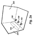
同時に、図2a乃至2c及び図3を参照すると、3つの光源102、104及び106を有する照明システム100は、照明システム100の動作中、部屋202のようなスペースに設けられる。図2aに図示されているように、3つの光源102、104及び106全てが、遠隔制御装置110によって、例えば部屋202の壁204に、第1照明パターン120を供給するよう制御される(S1)。第1パターン120は、図2aにおいては、照明される領域(即ち、光の方向)として図示されているが、当然、光源102、104、106によって放射される光の例えば色及び/又は輝度を含む光の他の特徴にも関してもよい。第1照明パターン120は、例えば、遠隔制御装置110を用いて、利用可能な照明設定の選択肢から選択されてもよく、又は遠隔制御装置110上の例えばボタンなどの制御手段を用いて規定される。ユーザが、第1照明パターン120に満足したら、前記ユーザは、好ましくは遠隔制御装置110を用いて、第1照明パターンを示す照明パラメータを検出し、記憶する(S2)。
At the same time, referring to FIGS. 2 a-2 c and FIG. 3, a
しかしながら、図2bに図示されているように、光源104が、機能しなくなり、例えば、バッテリ切れ、破損又はその元の位置からの除去などにより、光を放射するのを止め、その結果として、3つの光源102、104、106全てが機能していたときにあったような第1照明パターンと比べて異なると知覚される第2照明パターン122が供給される。これは、例えば、照明システム100を操作するユーザによって、又は照明システム100自体によって自動的に、気づかれる。システムを操作するユーザが、機能しなくなった光源104に気づく場合には、ユーザは、例えばセンサ112を用いて、「新しい」照明パターン、即ち、この場合には、第2照明パターン122を測定するために、光源102、106によって照明されている領域に、遠隔制御装置110を向け得る。遠隔制御装置110が、もう一度、今度は第2照明パターン122を示す後続照明パラメータを検出する(S3)ために用いられる。遠隔制御装置110は、(場合によっては、光源102、106の各々によって放射される個々の光についての情報を有する)後続照明パラメータを制御ユニット108に伝え、制御ユニット108は、照明システムの残りの(即ち、この場合には、機能している光源102、106を含む)光源のための制御信号の新しいセットを決定する。光源104が機能しなくなっているので、この光源のための駆動信号は、「光源104を使用しない」よう設定され得る。他の例においては、光源104が、異なる空間照明分布を持つ光源に置き換えられてもよく、更に別の照明パターン(図示せず)を生じさせ、制御ユニットからの他の調節を必要とする。
However, as illustrated in FIG. 2b, the
図2cにおいては、光源102及び106を制御する(S4)ための調節した制御信号を用いた結果が図示されている。光源102及び106のための制御信号は、2つの機能している光源102及び106からの光だけから生じる更なる第3照明パターン124と、第1照明パターン120との間の違いが最小限に抑えられるように適応されている。第3照明パターン124と、第1照明パターン120との間の違いを最小限に抑える処理は、例えば、センサ112を用いて連続して測定することによって、反復的に達成され得る。当然、数学的な計算を含む、違いの最小化を達成する他の方法も、可能であり、本発明の範囲内である。図2b及び2cは、参考のために、第1照明パターンを示している。
In FIG. 2c, the result is shown using the adjusted control signal to control the
更に、前記方法の動作は、照明システム100への更なる光源の導入を含むよう拡張され得る。このような実施の例は、光源の、第1照明システムから第2照明システムへの移動を含む。このような場合には、第2照明システムへ動かされている光源が、第2照明システムに既に存在する光源の間の「ネットワーク・トラフィック」をモニタしていてもよく、ネットワーク・トラフィックに基づいて、第2照明システムによって供給される共同照明パターンを決定してもよい。この概念は、「近傍プロファイリング」と呼ばれ得る。ネットワーク・トラフィックは、第2照明システムによって生成される、例えば、RF、IR、超音波又は他の信号に基づき得る。
Furthermore, the operation of the method can be extended to include the introduction of further light sources into the
本発明の特定の例示実施例に関して本発明を説明しているが、当業者には、多くの異なる変形例、修正例などが明らかになるであろう。開示されている実施例の変形は、当業者により、請求項記載の発明の実施において、図面、明細及び添付の請求項の研究から、理解され、達成され得る。例えば、上記の説明は、単一の照明パターンに関してなされているが、例えば一連の照明パターンとして示される複合照明パターンも、可能であり、本発明の範囲内である。複合照明パターンはまた、照明シーンとして例示されることができ、例えば、「夏の昼間の照明シーン」、「虹の照明シーン」として示され得る。上記のように、本発明によれば、光源の導入及び/又は除去は、機能している光源のための駆動信号を調節することによって、シーンを本質的に完全なままにしようとする試みをもたらすだろう。 Although the present invention has been described with respect to particular exemplary embodiments of the present invention, many different variations, modifications, etc. will become apparent to those skilled in the art. Variations of the disclosed embodiments can be understood and attained by those skilled in the art from studying the drawings, the specification and the appended claims, in the practice of the claimed invention. For example, while the above description has been made with reference to a single illumination pattern, a composite illumination pattern, for example shown as a series of illumination patterns, is possible and within the scope of the present invention. The composite lighting pattern can also be illustrated as a lighting scene, for example, shown as “summer daytime lighting scene”, “rainbow lighting scene”. As noted above, according to the present invention, the introduction and / or removal of a light source attempts to keep the scene essentially complete by adjusting the drive signal for the functioning light source. Will bring.
更に、請求項において、「有する」という用語は、他の要素又はステップを除外せず、単数形表記は、複数性を除外しない。 Further, in the claims, the term “comprising” does not exclude other elements or steps, and the singular form does not exclude a plurality.
Claims (13)
第1照明システム構成であって、各々が、前記第1照明システム構成の共同の第1照明パターンを一緒に形成する照明パターンを各々放射するよう構成される前記少なくとも2つの個々に制御可能な光源を有する第1照明システム構成を制御し、
前記第1照明パターンを示す照明パラメータの最初のセットを検出し、記憶し、
前記第1照明システム構成と異なる第2照明システム構成の個々に制御可能な光源によって共同形成される第2照明パターンを示す照明パラメータの次のセットを決定し、
前記照明パラメータの最初のセット及び前記照明パラメータの次のセットに依存して、前記第1照明パターンに近いものである第3照明パターンを共同形成するように、前記第2照明システム構成の前記光源を制御し、それによって、前記第1照明パターンと、前記第3照明パターンとの間の違いを最小限に抑えるよう構成される照明システム。 An illumination system comprising at least two individually controllable light sources and a control unit , the control unit being connectable to the at least two individually controllable light sources, the at least two individually controlled Configured to control possible light sources, the control unit further comprising:
The at least two individually controllable light sources configured to each emit a lighting pattern that together form a joint first lighting pattern of the first lighting system configuration. Controlling a first lighting system configuration comprising:
Detecting and storing an initial set of illumination parameters indicative of the first illumination pattern;
Determining a next set of illumination parameters indicative of a second illumination pattern that is co-formed by individually controllable light sources of a second illumination system configuration different from the first illumination system configuration ;
The light source of the second illumination system configuration to co-form a third illumination pattern that is close to the first illumination pattern, depending on the first set of illumination parameters and the next set of illumination parameters. A lighting system configured to control the difference between the first lighting pattern and the third lighting pattern .
第1照明システム構成であって、各々が、前記第1照明システム構成の共同の第1照明パターンを一緒に形成する照明パターンを各々放射するよう構成される少なくとも2つの個々に制御可能な光源を有する第1照明システム構成を制御するステップと、
前記第1照明パターンを示す照明パラメータの最初のセットを検出し、記憶するステップと、
前記第1照明システム構成と異なる第2照明システム構成の個々に制御可能な光源によって共同形成される第2照明パターンを示す照明パラメータの次のセットを決定するステップと、
前記照明パラメータの最初のセット及び前記照明パラメータの次のセットに依存して、前記第1照明パターンに近いものである第3照明パターンを共同形成するように、前記第2照明システム構成の前記光源を制御し、それによって、前記第1照明パターンと、前記第3照明パターンとの間の違いを最小限に抑えるステップとを有する方法。 A method for controlling a lighting system comprising at least two individually controllable light sources and a control unit comprising :
A first lighting system arrangement, each comprising at least two individually controllable light sources configured to each emit a lighting pattern that together form a joint first lighting pattern of said first lighting system arrangement ; Controlling a first lighting system configuration comprising :
Detecting and storing an initial set of illumination parameters indicative of the first illumination pattern;
Determining a next set of illumination parameters indicative of a second illumination pattern co-formed by individually controllable light sources of a second illumination system configuration different from the first illumination system configuration ;
The light source of the second illumination system configuration to co-form a third illumination pattern that is close to the first illumination pattern, depending on the first set of illumination parameters and the next set of illumination parameters. And thereby minimizing the difference between the first illumination pattern and the third illumination pattern .
Applications Claiming Priority (3)
| Application Number | Priority Date | Filing Date | Title |
|---|---|---|---|
| EP10150162 | 2010-01-06 | ||
| EP10150162.5 | 2010-01-06 | ||
| PCT/IB2010/056142 WO2011083394A1 (en) | 2010-01-06 | 2010-12-30 | Adaptable lighting system |
Publications (3)
| Publication Number | Publication Date |
|---|---|
| JP2013516734A JP2013516734A (en) | 2013-05-13 |
| JP2013516734A5 JP2013516734A5 (en) | 2014-02-06 |
| JP5705875B2 true JP5705875B2 (en) | 2015-04-22 |
Family
ID=43827501
Family Applications (1)
| Application Number | Title | Priority Date | Filing Date |
|---|---|---|---|
| JP2012547563A Active JP5705875B2 (en) | 2010-01-06 | 2010-12-30 | Adaptable lighting system |
Country Status (5)
| Country | Link |
|---|---|
| US (1) | US8878457B2 (en) |
| EP (1) | EP2522203B1 (en) |
| JP (1) | JP5705875B2 (en) |
| CN (1) | CN102687595B (en) |
| WO (1) | WO2011083394A1 (en) |
Families Citing this family (7)
| Publication number | Priority date | Publication date | Assignee | Title |
|---|---|---|---|---|
| US20140304110A1 (en) * | 2013-03-15 | 2014-10-09 | W.W. Grainger, Inc. | Procurement process utilizing a light sensor |
| JP6139017B2 (en) | 2013-04-15 | 2017-05-31 | フィリップス ライティング ホールディング ビー ヴィ | Method for determining characteristics of light source and mobile device |
| BR112015028959A2 (en) * | 2013-05-21 | 2017-07-25 | Koninklijke Philips Nv | first lighting device, lighting device system, and computer program product to operate a first lighting device |
| EP3002995A1 (en) * | 2014-10-01 | 2016-04-06 | Koninklijke Philips N.V. | Lighting device |
| US10448488B2 (en) * | 2015-04-27 | 2019-10-15 | Signify Holding B.V. | Lighting control module, a lighting system using the same and a method of setting a dimming level |
| CN111656865B (en) * | 2018-01-31 | 2023-06-02 | 昕诺飞控股有限公司 | Method and device for controlling a lighting system |
| ES2960522T3 (en) * | 2018-10-05 | 2024-03-05 | Signify Holding Bv | A method and controller for setting up a replacement lighting fixture in a lighting system |
Family Cites Families (19)
| Publication number | Priority date | Publication date | Assignee | Title |
|---|---|---|---|---|
| US5769527A (en) | 1986-07-17 | 1998-06-23 | Vari-Lite, Inc. | Computer controlled lighting system with distributed control resources |
| US6300724B1 (en) * | 1999-11-16 | 2001-10-09 | Fluid Light Technologies, Inc. | System and method for controlling rare gas illumination |
| CN100556225C (en) | 2002-12-16 | 2009-10-28 | 皇家飞利浦电子股份有限公司 | Be used for carrying out the system and method that lighting control networks recovers from master-failure |
| US7057354B2 (en) * | 2003-09-15 | 2006-06-06 | Cheerine Development (Hong Kong) Limited | Frequency controlled lighting system |
| JP4883517B2 (en) * | 2004-11-19 | 2012-02-22 | 学校法人福岡工業大学 | Three-dimensional measuring apparatus, three-dimensional measuring method, and three-dimensional measuring program |
| JP4652444B2 (en) | 2005-03-12 | 2011-03-16 | ルートロン エレクトロニクス カンパニー インコーポレイテッド | Handheld programmer for lighting control system |
| US7952292B2 (en) | 2005-04-22 | 2011-05-31 | Koninklijke Philips Electronics N.V. | Illumination control |
| JP5059008B2 (en) | 2005-09-19 | 2012-10-24 | ヴィアイピー 1 エーピーエス | Dynamic lighting color control |
| US8514210B2 (en) * | 2005-11-18 | 2013-08-20 | Cree, Inc. | Systems and methods for calibrating solid state lighting panels using combined light output measurements |
| KR20070093736A (en) * | 2006-03-15 | 2007-09-19 | 삼성전자주식회사 | Light emitting apparatus and control method thereof |
| JP4776463B2 (en) * | 2006-07-20 | 2011-09-21 | シャープ株式会社 | Surface light source device, illumination device, backlight device, and display device |
| JP5264731B2 (en) * | 2006-09-12 | 2013-08-14 | コーニンクレッカ フィリップス エレクトロニクス エヌ ヴィ | System and method for performing lighting copy paste operations in a lighting system |
| WO2008068693A1 (en) | 2006-12-06 | 2008-06-12 | Philips Intellectual Property & Standards Gmbh | Method and apparatus for replacing a device in a network |
| DE102007003345B4 (en) * | 2007-01-17 | 2010-07-29 | Erco Gmbh | Light Control System |
| JP2008210855A (en) * | 2007-02-23 | 2008-09-11 | Matsushita Electric Works Ltd | Led control system |
| KR101649577B1 (en) * | 2007-05-22 | 2016-08-19 | 코닌클리케 필립스 엔.브이. | Remote lighting control |
| CN101849434B (en) * | 2007-11-06 | 2013-11-20 | 皇家飞利浦电子股份有限公司 | Light control system and method for automatically rendering a lighting scene |
| WO2009112996A2 (en) | 2008-03-12 | 2009-09-17 | Koninklijke Philips Electronics N.V. | Configuration of a luminaire system |
| US8731690B2 (en) | 2008-04-23 | 2014-05-20 | Koninklijke Philips N.V. | Light system controller and method for controlling a lighting scene |
-
2010
- 2010-12-30 WO PCT/IB2010/056142 patent/WO2011083394A1/en active Application Filing
- 2010-12-30 JP JP2012547563A patent/JP5705875B2/en active Active
- 2010-12-30 US US13/519,410 patent/US8878457B2/en active Active
- 2010-12-30 EP EP10816389.0A patent/EP2522203B1/en active Active
- 2010-12-30 CN CN201080060831.8A patent/CN102687595B/en active Active
Also Published As
| Publication number | Publication date |
|---|---|
| US20120299510A1 (en) | 2012-11-29 |
| JP2013516734A (en) | 2013-05-13 |
| EP2522203B1 (en) | 2020-04-01 |
| EP2522203A1 (en) | 2012-11-14 |
| US8878457B2 (en) | 2014-11-04 |
| WO2011083394A1 (en) | 2011-07-14 |
| CN102687595B (en) | 2015-01-07 |
| CN102687595A (en) | 2012-09-19 |
Similar Documents
| Publication | Publication Date | Title |
|---|---|---|
| JP5705875B2 (en) | Adaptable lighting system | |
| JP5602024B2 (en) | light source | |
| JP5960761B2 (en) | Lighting system and method with improved signal-to-noise ratio | |
| EP3332611B1 (en) | Lighting control | |
| TWI522009B (en) | Lamp unit and method for controlling light sources | |
| JP6290463B2 (en) | Proxy for legacy lighting control components | |
| JP6508597B2 (en) | Lighting controller and control method of lighting device | |
| US9504114B2 (en) | Illumination control apparatus and illumination control method | |
| JP5299722B2 (en) | LED lighting device | |
| JP2016513332A (en) | Method and system for enabling a user to control a coded light source | |
| JP2009238399A (en) | Illumination system | |
| JP6107118B2 (en) | Lighting device and lighting system | |
| US20190353337A1 (en) | Custom universal light switch and dimmer | |
| KR101714362B1 (en) | Control Apparatus for Lighting Device Using Power Switching Operation and Controlling Method thereof | |
| CN112188711B (en) | Lighting system | |
| JP2009501675A (en) | Visual feedback for remotely controlled lighting equipment. | |
| US10842005B2 (en) | Assembly and method for controlling electronic equipment | |
| JP2019212558A (en) | Load control system | |
| KR102301817B1 (en) | Apparatus for controlling lighting based on mode of light sensor and method | |
| CN113196882B (en) | Control system for configuring lighting system and method thereof | |
| JP6454889B1 (en) | Load control system and load control device | |
| KR20220142856A (en) | Device and method for lighting control using power switch | |
| JP6092960B2 (en) | Lighting device and lighting system | |
| TW201742513A (en) | Control method of transmitting information by light | |
| CN112449459A (en) | System and method for matching light output from LED luminaire |
Legal Events
| Date | Code | Title | Description |
|---|---|---|---|
| A521 | Request for written amendment filed |
Free format text: JAPANESE INTERMEDIATE CODE: A523 Effective date: 20131210 |
|
| A621 | Written request for application examination |
Free format text: JAPANESE INTERMEDIATE CODE: A621 Effective date: 20131210 |
|
| A131 | Notification of reasons for refusal |
Free format text: JAPANESE INTERMEDIATE CODE: A131 Effective date: 20140902 |
|
| TRDD | Decision of grant or rejection written | ||
| A01 | Written decision to grant a patent or to grant a registration (utility model) |
Free format text: JAPANESE INTERMEDIATE CODE: A01 Effective date: 20150127 |
|
| A61 | First payment of annual fees (during grant procedure) |
Free format text: JAPANESE INTERMEDIATE CODE: A61 Effective date: 20150225 |
|
| R150 | Certificate of patent or registration of utility model |
Ref document number: 5705875 Country of ref document: JP Free format text: JAPANESE INTERMEDIATE CODE: R150 |
|
| S111 | Request for change of ownership or part of ownership |
Free format text: JAPANESE INTERMEDIATE CODE: R313113 |
|
| R350 | Written notification of registration of transfer |
Free format text: JAPANESE INTERMEDIATE CODE: R350 |
|
| R250 | Receipt of annual fees |
Free format text: JAPANESE INTERMEDIATE CODE: R250 |
|
| R250 | Receipt of annual fees |
Free format text: JAPANESE INTERMEDIATE CODE: R250 |
|
| S531 | Written request for registration of change of domicile |
Free format text: JAPANESE INTERMEDIATE CODE: R313531 |
|
| S533 | Written request for registration of change of name |
Free format text: JAPANESE INTERMEDIATE CODE: R313533 |
|
| R350 | Written notification of registration of transfer |
Free format text: JAPANESE INTERMEDIATE CODE: R350 |
|
| R250 | Receipt of annual fees |
Free format text: JAPANESE INTERMEDIATE CODE: R250 |
|
| R250 | Receipt of annual fees |
Free format text: JAPANESE INTERMEDIATE CODE: R250 |
|
| R250 | Receipt of annual fees |
Free format text: JAPANESE INTERMEDIATE CODE: R250 |
|
| R250 | Receipt of annual fees |
Free format text: JAPANESE INTERMEDIATE CODE: R250 |
|
| R250 | Receipt of annual fees |
Free format text: JAPANESE INTERMEDIATE CODE: R250 |