JP5703907B2 - Nonlinear Raman spectroscopy apparatus, nonlinear Raman spectroscopy system, and nonlinear Raman spectroscopy method - Google Patents
Nonlinear Raman spectroscopy apparatus, nonlinear Raman spectroscopy system, and nonlinear Raman spectroscopy method Download PDFInfo
- Publication number
- JP5703907B2 JP5703907B2 JP2011079473A JP2011079473A JP5703907B2 JP 5703907 B2 JP5703907 B2 JP 5703907B2 JP 2011079473 A JP2011079473 A JP 2011079473A JP 2011079473 A JP2011079473 A JP 2011079473A JP 5703907 B2 JP5703907 B2 JP 5703907B2
- Authority
- JP
- Japan
- Prior art keywords
- light
- fiber
- single mode
- wavelength
- mode fiber
- Prior art date
- Legal status (The legal status is an assumption and is not a legal conclusion. Google has not performed a legal analysis and makes no representation as to the accuracy of the status listed.)
- Expired - Fee Related
Links
Images


Classifications
-
- G—PHYSICS
- G01—MEASURING; TESTING
- G01N—INVESTIGATING OR ANALYSING MATERIALS BY DETERMINING THEIR CHEMICAL OR PHYSICAL PROPERTIES
- G01N21/00—Investigating or analysing materials by the use of optical means, i.e. using sub-millimetre waves, infrared, visible or ultraviolet light
- G01N21/62—Systems in which the material investigated is excited whereby it emits light or causes a change in wavelength of the incident light
- G01N21/63—Systems in which the material investigated is excited whereby it emits light or causes a change in wavelength of the incident light optically excited
- G01N21/65—Raman scattering
Landscapes
- Health & Medical Sciences (AREA)
- Nuclear Medicine, Radiotherapy & Molecular Imaging (AREA)
- Physics & Mathematics (AREA)
- Life Sciences & Earth Sciences (AREA)
- Chemical & Material Sciences (AREA)
- Analytical Chemistry (AREA)
- Biochemistry (AREA)
- General Health & Medical Sciences (AREA)
- General Physics & Mathematics (AREA)
- Immunology (AREA)
- Pathology (AREA)
- Investigating, Analyzing Materials By Fluorescence Or Luminescence (AREA)
Description
本技術は、非線形ラマン分光装置、この装置を用いた非線形ラマン分光システム及び非線形ラマン分光方法に関する。より詳しくは、ストークス光として広帯域光を用いるマルチプレックス・コヒーレント・アンチストークス・ラマン分光の装置、システム及び方法に関する。 The present technology relates to a nonlinear Raman spectroscopy apparatus, a nonlinear Raman spectroscopy system using the apparatus, and a nonlinear Raman spectroscopy method. More specifically, the present invention relates to an apparatus, system, and method for multiplex coherent anti-Stokes Raman spectroscopy using broadband light as Stokes light.
レーザラマン分光法は、ポンプ光として単一波長のレーザ光を被検体試料に照射し、その試料からの散乱光を分光する分析方法である。この散乱光であるストークス光又はアンチストークス光の波数のポンプ光に対するシフト量は、その被検体資料の物質固有の分子振動モードに対応している、物質によって特定のスペクトルとして観察される。このため、ラマン分光法は、赤外分光法と並んで分子指紋領域の分光法として、物質の解析・評価、医療診断、新薬や食品などの有機物の開発に、広く用いられている。 Laser Raman spectroscopy is an analysis method in which a sample sample is irradiated with laser light having a single wavelength as pump light, and scattered light from the sample is dispersed. The amount of shift of the wave number of the Stokes light or anti-Stokes light, which is the scattered light, with respect to the pump light is observed as a specific spectrum depending on the substance corresponding to the substance-specific molecular vibration mode of the specimen material. For this reason, Raman spectroscopy is widely used as a molecular fingerprint region spectroscopy along with infrared spectroscopy for the analysis and evaluation of substances, medical diagnosis, and the development of organic substances such as new drugs and foods.
また、非線形ラマン分光法は、前述した従来のレーザラマン分光法と同様にラマン散乱光を測定するものであるが、3次の非線形光学過程を利用している点が異なる。3次の非線形光学過程は、励起光であるポンプ光、プローブ光及びストークス光の3種の光を入射して、散乱される光を検出する方法であり、例えば、CARS(Coherent anti-Stokes Raman Scattering;コヒーレント・アンチ・ストークス・ラマン散乱)、CSRS(Coherent Stokes Raman Scattering;コヒーレント・ストークスラマン散乱)、誘導ラマン損失分光、誘導ラマン利得分光などがある。 Nonlinear Raman spectroscopy measures Raman scattered light in the same manner as the conventional laser Raman spectroscopy described above, except that it uses a third-order nonlinear optical process. Third-order nonlinear optical processes, the pump light is excitation light, is incident three kinds of light of the probe light and Stokes light, a method of detecting light scattered, for example, CARS (Coherent anti-Stokes There are Raman Scattering (coherent anti-Stokes Raman scattering), CSRS (Coherent Stokes Raman Scattering), stimulated Raman loss spectroscopy, stimulated Raman gain spectroscopy, and the like.
CARS分光法では、一般に、ポンプ光とこのポンプ光よりも波長が長いストークス光を被検体試料に照射し、試料から散乱されるポンプ光よりも波長が短い非線形ラマン散乱光を分光し、スペクトルを得ている(例えば、特許文献1〜3参照。)。また、従来、ストークス光を発生させるための光源として、白色光を使用する非線形ラマン分光方法も提案されている(特許文献4参照)。
In CARS spectroscopy, in general, pump light and Stokes light having a wavelength longer than that of the pump light are irradiated on the sample, and nonlinear Raman scattered light having a wavelength shorter than that of the pump light scattered from the sample is dispersed to obtain a spectrum. (For example, refer to
一方、前述した従来のCARS分光法では、ポンプ光やストークス光を生成するためのレーザ光は、数十fs〜数十psの超短パルス光が用いられているが、その場合、装置が高価でかつ複雑になるという問題点がある。そこで、従来、フォトニック結晶ファイバ(PCF)により、パルス幅が0.1〜10nsのパルス光を広帯域化して、スーパーコンティニューム光を生成する方法が提案されている(特許文献5参照)。 On the other hand, in the conventional CARS spectroscopy described above, ultrashort pulse light of several tens of fs to several tens of ps is used as laser light for generating pump light and Stokes light. In addition, there is a problem that it becomes complicated. Thus, conventionally, a method has been proposed in which a pulsed light having a pulse width of 0.1 to 10 ns is broadened by a photonic crystal fiber (PCF) to generate supercontinuum light (see Patent Document 5).
前述したCARS分光法などに代表される非線形ラマン分光法は、従来のラマン分光法に比べて、蛍光バックグランドの影響を回避することができ、更に、検出感度の向上が可能である。このため、特に、生体系の分子識別イメージング技術として、現在、研究開発が盛んに行われている。 Compared with the conventional Raman spectroscopy, the nonlinear Raman spectroscopy represented by the above-mentioned CARS spectroscopy can avoid the influence of the fluorescence background and can further improve the detection sensitivity. For this reason, research and development are currently being actively conducted as a molecular identification imaging technique for biological systems.
しかしながら、前述した従来の非線形ラマン分光法、特にマルチプレックスCARS分光法では、PCFや高非線形ファイバ(HNLF)などにより広帯域白色光を生成しているため、光損傷、特に入射端面近傍の光損傷が大きく、最大入射パワーが限られるという問題点がある。 However, in the above-described conventional nonlinear Raman spectroscopy, particularly multiplex CARS spectroscopy, broadband white light is generated by PCF, highly nonlinear fiber (HNLF), etc., so that optical damage, particularly near the incident end face, is not caused. There is a problem that the maximum incident power is limited.
一般に、PCFやHNLFを用いた場合、広帯域性を確保できるという長所があるが、これは、CARS分光においては、広帯域であるが故、1波長あたりの光パワーが低くなるという短所となる。また、PCFには、特殊な端面処理が必要となるなどの問題点もある。 In general, when PCF or HNLF is used, there is an advantage that a broadband property can be secured. However, in CARS spectroscopy, the optical power per one wavelength is lowered because of the broadband. The PCF also has a problem that special end face processing is required.
更に、PCFから発生されるスーパーコンティニューム光(広帯域光)のビームプロファイルは、一般的に、理想的なガウシアンビームとならない。そして、このようなビームプロファイルのレーザ光は、顕微分光法や顕微分光イメージングにおいて取得される画像の劣化の要因となるため、好ましくない。 Furthermore, the beam profile of supercontinuum light (broadband light) generated from the PCF is generally not an ideal Gaussian beam. The laser beam having such a beam profile is not preferable because it causes deterioration of an image acquired in the microspectroscopic method or microspectroscopic imaging.
そこで、本開示は、高効率でかつ安定性に優れた小型の非線形ラマン分光装置、非線形ラマン分光システム及び非線形ラマン分光方法を提供することを主目的とする。 Thus, the main object of the present disclosure is to provide a small-sized nonlinear Raman spectroscopic device, a nonlinear Raman spectroscopic system, and a nonlinear Raman spectroscopic method that are highly efficient and excellent in stability.
本発明者は、前述した問題点を解決するために、鋭意実験研究を行った結果、以下に示す知見を得た。特に、生体系への応用においては、分子指紋領域と呼ばれる分子振動スペクトル領域300〜3600cm−1の分光が重要である。このため、非線形ラマン分光法による顕微分光イメージングでは、入力するレーザビームの品質として非線形光学効果を大きくするため、ピークパワーが高いこと、ガウシアンビームが得られること及び偏光状態が直線偏光であることが求められている。
As a result of intensive experimental research to solve the above-described problems, the present inventor has obtained the following knowledge. In particular, in application to biological systems, spectroscopy in a molecular vibration
一方、シングルモードファイバ(SMF)から出射される光の空間強度分布は、出射光の波長がSMFのカットオフ波長近傍又はそれ以上の波長であれば、理想的なガウシアンビームとなる。そこで、本発明者は、ストークス光用の広帯域白色光を生成する際、PCFやHNLFの代わりに、安価で容易に入手可能なSMFを使用することについて検討した。その結果、本発明者は、SMFを使用すると、理想的なガウシアンビームが得られることも見出した。 On the other hand, the spatial intensity distribution of the light emitted from the single mode fiber (SMF) is an ideal Gaussian beam if the wavelength of the emitted light is near or higher than the cutoff wavelength of the SMF. The present inventors have, when generating a broadband white light for Stokes light, instead of the PCF and HNLF, was investigated using the inexpensive and readily available SMF. As a result, the inventor has also found that an ideal Gaussian beam can be obtained by using SMF.
また、非線形ラマン分光法においては、ポンプ光、プローブ光及びストークス光の3つのパルスの電場ベクトルの方向が一致している必要があり、これらの光発生部で偏光が直線偏光であることが望ましい。この点について、本発明者は、特定のSMF、特に、偏波面保存シングルモードファイバ(PM−SMF)を使用することにより、良好な直線偏光のストークス光が得られることを見出し、本発明に至った。 In the nonlinear Raman spectroscopy, the directions of the electric field vectors of the three pulses of the pump light, the probe light, and the Stokes light need to coincide with each other, and it is desirable that the polarized light is linearly polarized light in these light generation units. . In this regard, the present inventors have found that by using a specific SMF, in particular, a polarization-maintaining single-mode fiber (PM-SMF), excellent linearly polarized Stokes light can be obtained, leading to the present invention. It was.
即ち、本開示に係る非線形ラマン分光装置は、パルス幅が0.2〜10ns、パルスピークパワーが50〜5000W、波長が500〜1200nmのパルス光を出射する光源部と、前記パルス光から連続白色光を生成するシングルモードファイバと、を有し、前記パルス光からなるポンプ光兼プローブ光と、前記連続白色光からなるストークス光とを、測定対象の試料に照射し、そのラマンスペクトルを得るものである。
この装置では、前記シングルモードファイバとして、例えば偏波面保存シングルモードファイバを使用することができる。
その場合、光源部から導入されたパルス光の偏光面を回転させる半波長板を設け、この半波長板によってシングルモードファイバの進相軸又は遅相軸と平行になるように偏光面が回転されたパルス光がシングルモードファイバに入射する構成としてもよい。
また、ポンプ光兼プローブ光の偏光面の方向を、前記ストークス光の偏光面と一致させる半波長板を設けることもできる。
一方、シングルモードファイバのファイバ長は、例えば1〜20mとすることができる。
また、ポンプ光兼プローブ光とストークス光とが同時に試料に照射されるよう前記ポンプ光兼プローブ光の光路長を調整する光ファイバを備えていてもよい。
その場合、前記光ファイバとしては、例えば、数mW以下の低励起パワーを入力する場合であれば、シングルモードファイバや偏波面保存シングルモードファイバを使用することができる。また、数mW以上励起パワーを入力する場合であれば、ファイバコア径を適宜大きくして、ファイバコア径が8μm以上の偏波面保存シングルモードファイバ、コア径が100μm以下のマルチモードファイバ、ラージモードエリアファイバ又はフォトニッククリスタルラージモードエリアファイバを使用することができる。
That is, the nonlinear Raman spectroscopic device according to the present disclosure includes a light source unit that emits pulsed light having a pulse width of 0.2 to 10 ns, a pulse peak power of 50 to 5000 W, and a wavelength of 500 to 1200 nm, and a continuous white color from the pulsed light. A single-mode fiber that generates light, and irradiates the sample to be measured with pump light and probe light composed of the pulsed light and Stokes light composed of the continuous white light to obtain a Raman spectrum thereof It is.
In this apparatus, for example, a polarization-maintaining single mode fiber can be used as the single mode fiber.
In that case, a half-wave plate that rotates the polarization plane of the pulsed light introduced from the light source unit is provided, and the polarization plane is rotated by this half-wave plate so as to be parallel to the fast axis or the slow axis of the single mode fiber. The pulse light may be incident on the single mode fiber.
In addition, a half-wave plate can be provided in which the direction of the polarization plane of the pump light and probe light coincides with the polarization plane of the Stokes light.
On the other hand, the fiber length of the single mode fiber can be set to 1 to 20 m, for example.
Further, an optical fiber may be provided that adjusts the optical path length of the pump light / probe light so that the sample is simultaneously irradiated with the pump light / probe light and Stokes light.
In this case, as the optical fiber, for example, when a low pumping power of several mW or less is input, a single mode fiber or a polarization-preserving single mode fiber can be used. Also, when pumping power of several mW or more is input, the fiber core diameter is appropriately increased, a polarization-preserving single mode fiber having a fiber core diameter of 8 μm or more, a multimode fiber having a core diameter of 100 μm or less, a large mode Area fibers or photonic crystal large mode area fibers can be used.
本開示に係る非線形ラマン分光システムは、前述した非線形ラマン分光装置と、該非線形ラマン分光装置で計測されたラマン分光スペクトルを正規化する演算装置と、を有する。
このシステムでは、前記演算装置において、ω、ω´を波数(cm−1)としたとき、下記数式1に基づいてポンプ光のパワーPP、ストークス光の強度スペクトル分布SS(ω)から規格化因子RN(ω)を算出し、下記数式2に基づいて測定スペクトルSC(ω)を規格化因子RN(ω)で規格化して規格化スペクトルSN(ω)を求めることができる。
A nonlinear Raman spectroscopic system according to the present disclosure includes the above-described nonlinear Raman spectroscopic device and an arithmetic device that normalizes the Raman spectroscopic spectrum measured by the nonlinear Raman spectroscopic device.
In this system, when ω and ω ′ are wave numbers (cm −1 ) in the arithmetic unit, the standard is derived from the power P P of the pump light and the intensity spectrum distribution S S (ω) of the Stokes light based on the

その場合、前記非線形ラマン分光装置には、シングルモードファイバの出射側に、短波長側エッジ波長λe(nm)が下記数式3で表される範囲にあるロングパスフィルタ又はバンドパスフィルタを設けてもよい。なお、下記数式3において、λpはポンプ光の波長(nm)であり、λfは下記数式4により求められる値である。また、下記数式4において、ωmは測定最大波数(cm−1)である。
In that case, the nonlinear Raman spectroscopic apparatus may be provided with a long-pass filter or a band-pass filter in which the short-wavelength side edge wavelength λe (nm) is in the range represented by the following
本開示に係る非線形ラマン分光方法は、光源部から、パルス幅が0.2〜10ns、パルスピークパワーが50〜5000W、波長が500〜1200nmのパルス光を出射する工程と、シングルモードファイバにより、前記パルス光から連続白色光を生成する工程と、前記パルス光からなるポンプ光兼プローブ光及び前記連続白色光からなるストークス光を、測定対象の試料に照射し、そのラマンスペクトルを得る工程と、を有する。 The nonlinear Raman spectroscopy method according to the present disclosure includes a step of emitting pulsed light having a pulse width of 0.2 to 10 ns, a pulse peak power of 50 to 5000 W, and a wavelength of 500 to 1200 nm from a light source unit, and a single mode fiber, A step of generating continuous white light from the pulsed light, a step of irradiating a sample to be measured with pump light / probe light comprising the pulsed light and Stokes light comprising the continuous white light, and obtaining a Raman spectrum thereof; Have
本開示によれば、シングルモードファイバにより連続白色光からなるストークス光を生成しているため、高効率でかつ安定性に優れた小型の非線形ラマン分光装置及び非線形ラマン分光方法を実現することができる。 According to the present disclosure, since the Stokes light composed of continuous white light is generated by the single mode fiber, a small nonlinear Raman spectroscopic device and a nonlinear Raman spectroscopic method that are highly efficient and excellent in stability can be realized. .
以下、本開示を実施するための形態について、添付の図面を参照して詳細に説明する。なお、本開示は、以下に示す各実施形態に限定されるものではない。また、説明は、以下の順序で行う。
1.第1の実施の形態
(ストークス光の生成にシングルモードファイバを使用した装置の例)
2.第2の実施の形態
(ポンプ光及びプローブ光の光路上に光ファイバを配置した装置の例)
3.第3の実施の形態
(測定スペクトルを正規化処理する演算部を備えるシステムの例)
Hereinafter, modes for carrying out the present disclosure will be described in detail with reference to the accompanying drawings. In addition, this indication is not limited to each embodiment shown below. The description will be given in the following order.
1. 1. First embodiment (example of a device using a single-mode fiber to generate Stokes light)
2. Second Embodiment (Example of an apparatus in which an optical fiber is disposed on the optical path of pump light and probe light)
3. Third Embodiment (Example of a system including a calculation unit that normalizes a measurement spectrum)
<1.第1の実施の形態>
[装置の全体構成]
先ず、本開示の第1の実施形態に係る非線形ラマン分光装置について説明する。図1は本実施形態の非線形ラマン分光装置の構成を模式的に示す図である。本実施形態の非線形ラマン分光装置1は、CARS分光装置であり、図1に示すように、光源部10、ポンプ光・プローブ光生成部20、ストークス光生成部30、光照射部40及び計測部50が設けられている。
<1. First Embodiment>
[Overall configuration of the device]
First, the nonlinear Raman spectroscopic device according to the first embodiment of the present disclosure will be described. FIG. 1 is a diagram schematically showing the configuration of the nonlinear Raman spectroscopic apparatus of the present embodiment. The nonlinear
[光源部10]
光源部10は、少なくとも、パルス光を出射するレーザ11、及びパルス光をポンプ光・プローブ光生成部20とストークス光生成部30とに振り分ける偏光ビームスプリッタ13を備えている。そして、光源部10は、ポンプ光・プローブ光生成部20及びストークス光生成部30に向けて、所定のパルス光を出射する。
[Light source unit 10]
The
ここで、レーザ11は、パルス幅が0.2〜10ns、パルスピークパワーが50W〜5kW、波長が500〜1200nmのパルス光を発生可能なものであればよい。例えば、安価で小型の1064nmで発振するQスイッチ方式のサブナノ秒繰返しパルスを発生するNd:YAGレーザなどを使用することができる。また、Qスイッチ方式以外にも、モード同期方式のNd:YAG、Nd:YVO4又はNd:YLFピコ秒レーザ、及びYb系ドープファイバーピコ秒レーザなどを使用することもできる。
Here, the
更に、測定に短波長の光を用いる場合は、前述した各レーザからの光を励起光として、KTPやLBOなどの第2高調波(Second Harmonic Generation:SHG)発生用光学結晶を用いてSHG光を発生させてもよい。この場合、励起光が1064nmであれば、第2高調波発生による波長変換後の波長は532nmとなる。このように、本実施形態の非線形ラマン分光装置1では、波長が532nm又は1064nmの光を発するものを好適に使用することができる。
Further, when using light of a short wavelength for measurement, the light from each laser described above is used as excitation light, and SHG light using an optical crystal for second harmonic generation (SHG) generation such as KTP or LBO. May be generated. In this case, if the excitation light is 1064 nm, the wavelength after wavelength conversion by the second harmonic generation is 532 nm. Thus, in the nonlinear
なお、光源部10から出射されるパルス光の波長は、これらに限定されるものではなく、例えばNd:YAGレーザの場合、1064nm以外に、波長が1319nm、1122nm及び946nmの光を発振することが可能である。また、Nd:YVO4レーザの場合は、1064nm以外に、波長が1342nm及び914nmの光を発振することが可能である。更に、Nd:YLFレーザの場合は、波長1053nm又は1047nmの光を、Yb:YAGレーザの場合は、波長1030nmの光を、それぞれ発振することができる。
The wavelength of the pulsed light emitted from the
そして、これらの波長を基本波として、第2高調波を発生させると、532nm以外にも、波長が660nm、561nm、473nm、671nm、457nm、527nm、523nm、515nmのSHG光が得られる。 When second harmonics are generated using these wavelengths as fundamental waves, SHG light having wavelengths of 660 nm, 561 nm, 473 nm, 671 nm, 457 nm, 527 nm, 523 nm, and 515 nm can be obtained in addition to 532 nm.
ただし、パルス幅を0.2ns未満にすると、レーザの機構が複雑になり、高価なものとなる。一方、パルス幅が10nmを超えると、1ショットあたりのパルスエネルギーが大きくなりすぎて、具体的にはレーザ光のパルスエネルギーが5μJ以上となり、光ファイバ端面の損傷が生じたり、ストークス光の性能が不安定になったりすることがある。また、当然のことながら、レーザ動作時の消費電力が増加する。なお、レーザ11から出射されるパルス光のパルス幅は、0.4〜5nsであることが好ましい。
However, if the pulse width is less than 0.2 ns, the laser mechanism becomes complicated and expensive. On the other hand, when the pulse width exceeds 10 nm, the pulse energy per shot becomes too large. Specifically, the pulse energy of the laser light becomes 5 μJ or more, the end face of the optical fiber is damaged, and the Stokes light performance is reduced. It may become unstable. Naturally, power consumption during laser operation increases. Note that the pulse width of the pulsed light emitted from the
長さが短い光ファイバ内において、連続白色光を取得するための3次の非線形光学効果を得るためには、パルス光のピークパワーは高い方が好ましい。そこで、本実施形態の非線形ラマン分光装置1では、パルスエネルギーの増加を抑えるため、ピークパワーを高くする分、パルス幅を短くして、1ショットあたりのパルスエネルギーを下げ、繰り返し周波数に応じて平均パワーが大きくならないようにする。例えば、パルス幅が前述した範囲内で、繰り返し周波数が10〜50kHzの場合には、平均パワーが250mW以下になるようにする。
In order to obtain a third-order nonlinear optical effect for obtaining continuous white light in an optical fiber having a short length, it is preferable that the peak power of pulsed light is high. Therefore, in the nonlinear Raman
このような仕様を満たす光源部10としては、例えば、受動Qスイッチ方式のNd:YAG固体レーザ(ALPHALAS社製 PLUSELAS P−1064−300)に、第2高調波発生用KTP結晶SHGユニットを装備した構成が考えられる。この構成の場合、例えば、波長:532nm、平均パワー:100mW、パルス幅:600ps、繰返し周波数:30kHzの光を出射することができる。
As the
また、光源部10には、レーザ11と偏光ビームスプリッタ13との間に、半波長板12が配置されていてもよい。半波長板12は、レーザ11から出射した光の偏光面を回転させる偏光素子であり、その光学軸をθ回転させると、通過後のレーザ光の偏光面は2θ回転する。これにより、レーザ11から出射した光が垂直偏光と水平偏光とに分配されるため、偏光ビームスプリッタ13において、励起パルス光4とポンプ光兼プローブ光(以下、単にポンプ光という)3とに好適に分配することができる。
In the
[ポンプ光・プローブ光生成部20]
ポンプ光・プローブ光生成部20には、光源部10から入射したパルス光(ポンプ光3)を、後述するストークス光5と同時に照射するために、光路長調整機構が設けられている。具体的には、ポンプ光3を、複数のミラー22a〜22d,23a,23b,24,25a,25bで反射することにより、光路長を調整して、ストークス光5とタイミングを合わせる。
[Pump light / probe light generation unit 20]
The pump light / probe
なお、光路調整機構は、図1に示す構成に限定されるものではなく、例えば、ミラー22a〜22d,23a,23bの光学配置により、ポンプ光3の光路長を、ストークス光5の光路長と一致させることができれば、ミラー24,25a,25bは不要となる。
The optical path adjustment mechanism is not limited to the configuration shown in FIG. 1. For example, the optical path length of the
また、シングルモードファイバ32として、後述する偏波面保存シングルモードファイバを使用する場合には、最初のミラー22aの前に、ポンプ光3の偏光面の方向を、ストークス光5の偏光面の方向に一致させるための半波長板21を配置する。なお、通常のシングルモードファイバを使用する場合は、半波長板21は不要である。
When a polarization-preserving single mode fiber, which will be described later, is used as the
[ストークス光生成部30]
ストークス光生成部30は、光源部10から入射したパルス光4から連続白色光であるストークス光5を生成するものであり、少なくとも、シングルモードファイバ32を備えている。ここで、ストークス光5の波長域は、分子指紋領域(ラマンシフト量で300〜3600cm−1)に対応するストークス光の波長であり、下記数式5により表される。なお、下記数式5におけるλはストークス光の波長(nm)、λpはポンプ光の波長(nm)であり、また、波数ω(cm−1)と波長λ(nm)との関係は、下記数式6で表すことができる。
[Stokes light generation unit 30]
The Stokes
そして、ストークス光生成部30において生成されるストークス光5の波長λは、例えば、ポンプ光3の波長λpが532nmの場合は540〜660nmであり、ポンプ光3の波長λpが1064nmの場合は1100〜1725nmである。
Then, the wavelength λ of the Stokes light 5 generated in the Stokes
また、ストークス光生成部30に設けられるシングルモードファイバ32は、ファイバ長が1〜20mのものであればよい。シングルモードファイバ32の長さが1m未満の場合、平坦な連続白色光が得られないことがあり、また、ファイバ長が20mを超えると、スペクトル全体の発生効率が低下すると共に、計測対象外の波長帯の光が増加する。なお、シングルモードファイバ32の長さは、3〜10mであることが好ましく、これにより、必要な波長帯域の連続白色光を、効率的にかつ安定して生成することができる。
Moreover, the
更に、シングルモードファイバ32のカットオフ波長は、励起パルス光4の波長にほぼ等しいものを選択することが望ましい。励起パルス光4の波長よりもカットオフ波長が短い場合は、ファイバへの入力結合効率が低下し、ストークス光5の生成効率や帯域幅が低下することがある。また、励起パルス光4の波長よりもカットオフ波長が長い場合は、ストークス光5のビームのモードがTEM00にならず、高次モードが混在し、単一のガウシアンビームが得られなくなる。なお、前述した要件を満たし、本実施形態の非線形ラマン分光装置1に使用可能なシングルモードファイバ32としては、例えば、Nufern社製 460HP,630HPなどが挙げられる。
Further, it is desirable to select a cutoff wavelength of the
更にまた、シングルモードファイバ32は、前述した特性を有する偏波面保存シングルモードファイバを使用することが望ましい。これにより、直線偏光のストークス光5が得られるため、通常は直線偏光として用いられるポンプ光3と偏光面を一致させることができるため、CARS信号を2倍程度増大することが可能となる。なお、本実施形態の非線形ラマン分光装置1に使用可能な偏波面保存シングルモードファイバとしては、例えば、Nufern社製 PM−460−HP,PM−630−HP、及びFIBERCORE社製 HB8600などが挙げられる。
Furthermore, as the
なお、シングルモードファイバ32に、励起パルス光4を導入する際は、開口係数をファイバの受光NAに合わせるため、開口数NAが0.1〜0.25の範囲にある対物レンズを用いることが望ましい。一方、シングルモードファイバ32の出射側には、ストークス光5のビーム径を、ポンプ光3のビーム径と一致させるため、開口数NAが0.2〜0.6の対物レンズを用いることが望ましい。
When introducing the
シングルモードファイバ32として偏波面保存シングルモードファイバを使用する場合には、励起パルス光4の偏光面の方向を、偏波面保存シングルモードファイバの光学軸(高速軸又は低速軸)に一致させるため、半波長板31を配置する。なお、通常のシングルモードファイバを使用する場合は、半波長板31は不要である。
When using a polarization-maintaining single-mode fiber as the single-
また、このストークス光生成部30には、シングルモードファイバ32の出射面側に、ロングパスフィルタ33が配置されている。ロングパスフィルタ33は、シングルモードファイバ32で発生した白色光の短波長側の光を反射し、長波長側の光のみを透過すものであり、これにより、生成したストークス光5から、不要な波長域の光を除去することができる。市販の高性能なロングパスフィルタでは、光学濃度6〜7の選択比を有するものが入手可能であり、本実施形態の非線形ラマン分光装置1では、例えばSemrock社製 LP03−532RU−25などを使用することができる。
In the Stokes
更に、ストークス光生成部30には、ストークス光5の光路を変えて、光照射部40に導入するためのミラー34が設置されていてもよい。
Further, the Stokes
[光照射部40]
光照射部40は、ポンプ光・プローブ光生成部20から出射したポンプ光3と、ストークス光生成部30から出射したストークス光5が同軸になるよう重ね合わせ、同時に試料2に照射するものである。この光照射部40の構成は、特に限定されるものではないが、例えば、ノッチフィルタ41、ビームエキスパンダ42,43、ミラー44、対物レンズ45などで構成することができる。
[Light irradiation unit 40]
The
ここで、ビームエキスパンダ42,43は、対物レンズ45の入射瞳径に、ビーム径を合わせるためのものである。例えば、ビーム径が約2mmの場合、3倍のビームエキスパンダを通過させることにより、対物レンズ45に入射時のビーム径を約6mmにすることができる。また、ノッチフィルタ41としては、例えばSemrock社製 NF−532U−25などを使用することができる。
Here, the
[計測部50]
計測部50は、試料2から発せられたCARS光を測定するものであり、例えば、対物レンズ51、ショートパスフィルタ52及び分光器53などが設けられている。ショートパスフィルタ52は、ポンプ光3及びストークス光5を遮断し、CARS光のみを通過させるものである。同時に、試料で発生した蛍光も、ポンプ光3の波長よりも長波長であるため、ポンプ光3及びストークス光5と同様に効率良く遮断することができる。
[Measurement unit 50]
The
市販の高性能なショートパスフィルタとしては、光学濃度6〜7の選択比を有するものが入手可能であり、本実施形態の非線形ラマン分光装置1では、例えばSemrock社製 SP01−532RU−25などを使用することができる。
As a commercially available high-performance short pass filter, a filter having an optical density of 6 to 7 is available. For example, the nonlinear Raman
分光器53は、例えば、熱ノイズを低減するために冷却機能を備えたCCD(Charge Coupled Device Image Sensor)やCMOS(Complementary Metal Oxide Semiconductor)アレイ検出器を装着したポリクロメータ、モノクロメータ又はPMT(Photomultiplier Tube:光電子増倍管)などを使用することができる。そして、ポリクロメータとしては、例えばSHAMROCK社製 SR−303iを使用することができ、その場合、1200本/mmの回折格子が用いられる。また、CCD検出器には、ANDOR社製 NEWTON DU970N BVを使用することができる。
The
ここで、CARS光は、微弱な光であるため、損失を可能な限り抑えることが望ましい。また、計測部50は、周囲の外光を十分に遮蔽する構成となっていることが望ましい。更に、分光器53の入射スリットには、レンズ系を用いてCARS光を導入してもよく、又は、図1に示すように、マルチモード光ファイバ54を用いてCARS光を導入することもできる。
Here, since CARS light is weak light, it is desirable to suppress loss as much as possible. Moreover, it is desirable that the
[非線形ラマン分光装置1の動作]
次に、本実施形態の非線形ラマン分光装置1の動作、即ち、非線形ラマン分光装置1を使用して、試料2のCARSスペクトルを測定する方法について説明する。本実施形態の非線形ラマン分光装置1においては、先ず、光源部10において、レーザ11から出射されたパルス光を、偏光ビームスプリッタ13によって2分割し、それぞれポンプ光・プローブ光生成部20とストークス光生成部30とに導入する。
[Operation of Nonlinear Raman Spectrometer 1]
Next, the operation of the nonlinear Raman
その際、レーザ11から出射したパルス光を、半波長板12によりその偏光面を回転した後、偏光ビームスプリッタ13により分割してもよい。これにより、分配比を調整することができる。
At this time, the pulsed light emitted from the
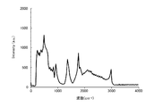
そして、ストークス光生成部30に入射したパルス光4は、シングルモードファイバ32に入射し、連続白色光であるストークス光5に変換される。図2は横軸に波長をとり、縦軸に強度をとって、長さ6mのシングルモードファイバを使用して生成したストークス光のスペクトルを示す図である。なお、図2に示すスペクトルは、波長532nm、入射パワー40mwのパルス光4から生成した白色連続光のスペクトルである。
The
ここで、シングルモードファイバ32として偏波面保存シングルモードファイバを使用する場合には、半波長板31を介して、光源部10から導入されたパルス光4をシングルモードファイバ32に入射させる。具体的には、半波長板31によって、パルス光4の偏光面を回転し、偏光面がシングルモードファイバ32の進相軸又は遅相軸と平行になるようにする。これにより、偏波面保存シングルモードファイバ内での偏光保存性が確保される。
Here, when a polarization-maintaining single mode fiber is used as the
図3は横軸に波長をとり、縦軸に強度をとって、偏波面保存シングルモードファイバの進相軸又は遅相軸に、入射励起光の偏波面を一致させたときのシングルモードファイバからの出射光の波長分布を示す図である。図3に示すように、進相軸又は遅相軸に検光子の方位を一致させ、出射光のスペクトル強度分布を測定すると、ほぼ全ての波長に対して、いずれかを消光することができ、単一直線偏光特性を有するストークス光5を生成することができる。なお、図3に示す分布線について、どちらが進相軸又は遅相軸であるかは、特定していない。 In FIG. 3, the horizontal axis indicates the wavelength, the vertical axis indicates the intensity, and the single-mode fiber when the polarization plane of the incident excitation light coincides with the fast axis or the slow axis of the polarization-maintaining single-mode fiber. It is a figure which shows wavelength distribution of the emitted light. As shown in FIG. 3, when the orientation of the analyzer coincides with the fast axis or the slow axis and the spectral intensity distribution of the emitted light is measured, one can be quenched for almost all wavelengths, Stokes light 5 having a single linear polarization characteristic can be generated. Note that it is not specified which of the distribution lines shown in FIG. 3 is the fast axis or the slow axis.
また、光照射部40に導入する前に、シングルモードファイバ32から出射したストークス光5を、ロングパスフィルタ33を通過させて、短波長側の成分を除去する。具体的には、例えば励起パルス光4が532nmの場合は、この励起パルス光4も含むように、540nmよりも波長が短い成分を除去する。これにより、シングルモードファイバ32から出射される光に含まれる不要な短波長成分を遮断し、測定したいCARSスペクトルの信号対ノイズ(バックグランド)の比を向上させることができる。
Further, before being introduced into the
一方、ポンプ光・プローブ光生成部20に入射したパルス光(ポンプ光3)は、ストークス光5と同時に光照射部40に導入されるように、複数のミラー22a〜22d,23a,23b,24,25a,25bにより、その光路長が調整される。その際、半波長板21により、ポンプ光3の偏光面の方向を、ストークス光5の偏光面の方向と一致させる。これにより、3次の非線形光学過程を高効率で利用することができ、CARSスペクトルの信号対ノイズ(バックグラウンド)比を向上させることができる。
On the other hand, the pulsed light (pump light 3) incident on the pump light / probe
光照射部40に導入されたポンプ光3及びストークス光5は、ノッチフィルタ41においてポンプ光3が反射し、ストークス光5は透過する。なお、ノッチフィルタ41の代わりに、ロングパスフィルタを使用することもできる。そして、ポンプ光3及びプローブ光5は、ビームエキスパンダ42,43において、対物レンズ45の入射瞳径に合うようビーム径が拡大された後、対物レンズ45を介して、試料2に照射される。図4は横軸に波長をとり、縦軸に強度をとって、長さ6mのシングルモードファイバを使用して生成したストークス光と、ポンプ光のスペクトルを示す図である。
The
そして、計測部50において、試料2から発せられたCARS光を検出し、ラマンスペクトルを得る。具体的には、試料2から発せられたCARS光を、対物レンズ51で集光した後、ショートパスフィルタ52でポンプ光3やストークス光5などの不要光を遮断した後、分光器53において検出する。
And in the
図5は横軸に波長をとり、縦軸に強度をとって、厚さが2mmのポリメタクリル酸メチル板のCARSスペクトルを示す図である。なお、図5に示すスペクトルは、対物レンズ45にNA0.45のものを、対物レンズ51にNA0.3のものを使用し、レーザ11の波長を532nm、繰り返し周波数を30kHz、パルス幅を約600psとして測定した。また、対物レンズ45から出射したポンプ光3の入射平均パワーは4mW、ストークス光5の平均パワーは6mWであり、CCD検出器の露光時間は500msとした。
FIG. 5 is a diagram showing a CARS spectrum of a polymethyl methacrylate plate having a thickness of 2 mm, with the horizontal axis representing wavelength and the vertical axis representing intensity. The spectrum shown in FIG. 5 uses NA 0.45 for the
図5に示すように、本実施形態の非線形ラマン分光装置1によれば、500〜3000cm−1の分子指紋領域をカバーする広い範囲で、良好なCARS分光スペクトルが得られた。そして、本実施形態の非線形ラマン分光装置1では、時間遅延などの調整の動作が不要となり、一括してこの帯域のスペクトルを取得することが可能となる。
As shown in FIG. 5, according to the nonlinear
以上詳述したように、本実施形態の非線形ラマン分光装置1は、シングルモードファイバ32によりストークス光5を生成しているため、構成を簡素化することができ、装置の小型化及び低コスト化を実現することができる。また、シングルモードファイバ32は、出力がガウシアンビームとなり、また入射端面の損傷が少ないため、結合方法やアライメントが簡単で、安定性の高いストークス光5が得られる。
As described above in detail, the nonlinear
なお、通常のSMFを、カスケード誘導ラマン散乱における連続白色光源に使用した例は、従来より知られているが、非線形ラマン分光法への適用は報告がない。これは、SMFのカスケード誘導ラマン散乱光では、複数のピークが表れるためと考えられる。 Incidentally, the normal S MF, examples of using the continuous white light source in the cascade stimulated Raman scattering is known conventionally, application to non-linear Raman spectroscopy no report. This is considered because a plurality of peaks appear in the SMF cascade stimulated Raman scattering light.
また、特許文献5に記載の非線形分光計測システムでは、スーパーコンティニューム光(広帯域光)の偏光状態については特に記載されていないが、コヒーレントな3次の非線形光学過程を効果的に利用するためには、ポンプ光、プローブ光及びストークス光(広帯域光)の偏光が一致した直線偏光になっていることが重要である。これに対して、本実施形態の非線形ラマン分光装置1では、ポンプ光3の偏光面の方向を、ストークス光5の偏光面の方向と一致させているため、3次の非線形光学過程を高効率で利用することができる。
In addition, in the nonlinear spectroscopic measurement system described in Patent Document 5, although the polarization state of supercontinuum light (broadband light) is not particularly described, in order to effectively use a coherent third-order nonlinear optical process. It is important that the polarization of the pump light, the probe light, and the Stokes light (broadband light) is linearly polarized. On the other hand, in the nonlinear
特に、偏光波面保存シングルモードファイバを使用した装置は、ポンプ光とストークス光のビーム調整(ビーム径を同一にし、方向を揃えるアライメント)を容易に行うことができ、顕微分光やイメージングに好適である。 In particular, an apparatus using a polarization wavefront-preserving single mode fiber can easily perform beam adjustment of pump light and Stokes light (alignment with the same beam diameter and the same direction), and is suitable for microscopic light and imaging. .
<2.第2の実施の形態>
[装置の全体構成]
次に、本開示の第2の実施形態に係る非線形ラマン分光装置について説明する。図6は本実施形態の非線形ラマン分光装置の構成を模式的に示す図である。なお、図6においては、図1に示す第1の実施形態の非線形ラマン分光装置1の構成と同じものには、同じ符号を付し、詳細な説明は省略する。
<2. Second Embodiment>
[Overall configuration of the device]
Next, a nonlinear Raman spectroscopic device according to the second embodiment of the present disclosure will be described. FIG. 6 is a diagram schematically showing the configuration of the nonlinear Raman spectroscopic apparatus of the present embodiment. In FIG. 6, the same components as those of the nonlinear
図6に示すように、本実施形態の非線形ラマン分光装置61は、ポンプ光・プローブ光生成部70の光路調整機構が、ミラーによる反射ではなく、所定長の光ファイバ73を通過させる構成となっている。具体的には、光源部10から導入されたパルス光は、ミラー71aによりその光路が変更されて、光ファイバ73に入射する。そして、光ファイバ73を通過することによりその光路長が調整された後、ミラー71bにより光路が変更されて、光照射部40に出射される。
As shown in FIG. 6, the nonlinear
(ポンプ光・プローブ光生成部70)
ポンプ光・プローブ光生成部70に配置される光ファイバ73としては、例えば、数mW以下の低励起パワーを入力する場合であれば、シングルモードファイバや偏波面保存シングルモードファイバを使用することができる。これは、励起パワーが低い場合は、ファイバ内でカスケードに誘導ラマン散乱光が発生せず、単なる光伝送用として用いることができるためである。このような場合に使用可能なシングルモードファイバとしては、Nufern社製 630HPなどが挙げられ、偏波面保存ファイバとしては、Nufern社製 PM−460−HP及びFIBERCORE社製 HB8600などが挙げられる。
(Pump light / probe light generator 70)
As the
一方、励起パワーが次第に大きくなると、誘導ラマン散乱光が発生し、単一波長のポンプ・プローブパルスを送ることができなくなる。本発明者の実験によれば、誘導ラマン散乱が起こらない閾値は、励起入力パワーが約5mWまでであった。このため、数mW以上の励起パワーを入力する場合は、ファイバ径を適宜大きくし、例えばファイバコア径が8μm以上の偏波面保存シングルモードファイバ、コア径が100μm以下のマルチモードファイバ、又はいわゆるラージモードエリアファイバ、フォトニッククリスタルラージモードエリアファイバなどを使用することが望ましい。 On the other hand, when the excitation power is gradually increased, stimulated Raman scattered light is generated, and a pump / probe pulse having a single wavelength cannot be transmitted. According to the inventors' experiment, the threshold value at which stimulated Raman scattering does not occur is that the excitation input power is up to about 5 mW. Therefore, when inputting excitation power of several mW or more, the fiber diameter is appropriately increased, for example, a polarization-preserving single mode fiber having a fiber core diameter of 8 μm or more, a multimode fiber having a core diameter of 100 μm or less, or a so-called large mode It is desirable to use a mode area fiber, a photonic crystal large mode area fiber, or the like.
その際、シングルモードファイバの場合、例えばNufern社製 SMF−28−J9などを使用することができ、偏波面保存シングルモードファイバの場合、例えばNufern社製 PM1550−HPなどを使用することができる。また、ラージモードエリアファイバの場合、例えばTHORLAB社製 P−10/125DC,P−25/240DC,P−40/140DCなどを使用することができる。ラージモードエリアフォトニッククリスタルファイバの場合は、例えばNKT PHOTONIC社製 LMA−20などを使用することができる。エンドレスシングルモードフォトニッククリスタルファイバの場合は、例えばNKT PHOTONIC社製 ESM−12−01などを使用することができる。 At that time, in the case of a single mode fiber, for example, SMF-28-J9 manufactured by Nufern can be used, and in the case of a polarization preserving single mode fiber, for example, PM1550-HP manufactured by Nufern can be used. In the case of a large mode area fiber, for example, P-10 / 125DC, P-25 / 240DC, P-40 / 140DC, etc. manufactured by THORLAB can be used. In the case of a large mode area photonic crystal fiber, for example, LMA-20 manufactured by NKT PHOTONIC can be used. In the case of an endless single mode photonic crystal fiber, for example, ESM-12-01 manufactured by NKT PHOTONIC can be used.
ここで、シングルモードファイバ32に偏波面保存シングルモードファイバを使用する場合には、光ファイバ73の前に、ポンプ光3の偏光面の方向を、ストークス光5の偏光面の方向に一致させるための半波長板72を配置する。なお、通常のシングルモードファイバを使用する場合は、半波長板72は不要である。
Here, when a polarization plane preserving single mode fiber is used as the
(光源部10)
本実施形態の非線形ラマン分光装置61においては、光源部10に、第2高調波発生用光学結晶14が配置されている。そして、この第2高調波発生用光学結晶14により、レーザ11から出射した励起光を波長変換してポンプ光としている。具体的には、例えば励起光が1064nmの場合、波長変換により532nmの緑色光となる。
(Light source unit 10)
In the nonlinear
本実施形態の非線形ラマン分光装置61では、光ファイバ73によりポンプ光3の光路長を調整しているため、ストークス光5とのタイミング調整が容易であり、かつ装置を小型化することが可能となる。CARS分光法では、ポンプ光3とストークス光5とが試料の測定ポイントに同時に到達する必要があるが、光ファイバ73を使用することにより、容易に、ポンプ光3の光路長と、ストークス光5の光路長とを同じにすることができる。
In the nonlinear
なお、本実施形態における上記以外の構成及び効果は、前述した第1の実施形態と同様である。 The configuration and effects other than those described above in the present embodiment are the same as those in the first embodiment described above.
<3.第3の実施の形態>
[システムの全体構成]
次に、本開示の第3の実施形態に係る非線形ラマン分光システムについて説明する。図7は本実施形態の非線形ラマン分光システムの構成を示す概念図である。なお、図7においては、図1に示す第1の実施形態の非線形ラマン分光装置1の構成と同じものには、同じ符号を付し、詳細な説明は省略する。
<3. Third Embodiment>
[System overall configuration]
Next, a nonlinear Raman spectroscopy system according to the third embodiment of the present disclosure will be described. FIG. 7 is a conceptual diagram showing the configuration of the nonlinear Raman spectroscopy system of this embodiment. In FIG. 7, the same components as those of the nonlinear
図7に示すように、本実施形態の非線形ラマン分光システム81は、前述した第1の実施形態の非線形ラマン分光装置1を備えたシステムであり、ラマン分光装置1の計測部50に、演算部80が接続されている。
As shown in FIG. 7, the nonlinear
[演算部80]
演算部80には、演算装置である電子計算機と、表示装置などが設けられており、計測部50の分光器で検出したCARSスペクトルの分布を正規化し、その結果などを表示する。以下、正規化のための具体的演算処理方法について説明する。
[Calculation unit 80]
The
マルチプレックスCARSスペクトルには、縮退4光波混合(2−color CARS)成分と、非縮退4光波混合(3−color CARS)成分とが含まれている(Young Jong Lee and Marcus T. Cicerone: “Single-shot interferometric approach to background free broadband coherent anti-Stokes Raman scattering spectroscopy”, 5 January 2009 / Vol. 17, No. 1 / OPTICS EXPRESS 123 参照)。 The multiplex CARS spectrum includes a degenerate four-wave mixing (2-color CARS) component and a non-degenerate four-wave mixing (3-color CARS) component (Young Jong Lee and Marcus T. Cicerone: “Single -shot interferometric approach to background free broadband coherent anti-Stokes Raman scattering spectroscopy ”, 5 January 2009 / Vol. 17, No. 1 / OPTICS EXPRESS 123).
ここで、CARS分光法では、縮退4光波混合(2−color CARS)成分はポンプ光とプローブ光が同一波長、ストークス光がそれらと異なる場合で、一般にはこれを狭義の意味でCARSスペクトルと呼ばれることが多い。一方、マルチプレックスCARSでは、ポンプ光、プローブ光及びストークス光の波長が全て異なる非縮退4光波混合(3−color CARS)成分が、前述した縮退4光波混合(2−color CARS)成分と同一のアンチストークスラマン散乱光になる場合がある。 Here, in CARS spectroscopy, the degenerate four-wave mixing (2-color CARS) component is the case where the pump light and the probe light have the same wavelength and the Stokes light is different from them, and this is generally called the CARS spectrum in a narrow sense. There are many cases. On the other hand, in multiplex CARS, the non-degenerate four-wave mixing (3-color CARS) component in which the wavelengths of the pump light, the probe light, and the Stokes light are all different is the same as the above-described degenerate four-wave mixing (2-color CARS) component. It may become anti-Stokes Raman scattering light.
一方、本実施形態の非線形ラマン分光システム81で使用している非線形ラマン分光装置1では、ポンプ光及びプローブ光が、ストークス光(連続白色光)に比べて、十分狭帯域の線スペクトルと見なせる。このため、縮退4光波混合(2−color CARS)成分I2−color(ω)は、ポンプ光のパワーPPの2乗とストークス光強度分布SS(ω)の積に比例し、下記数式7で表される。なお、下記数式7におけるωは波数(cm−1)である。
On the other hand, in the nonlinear Raman
また、非縮退4光波混合(3−color CARS)成分I3−color(ω)は、連続広帯域光のスペクトル内にある2つの波長成分(波数成分)が、ポンプ光及びストークス光の役目を行う。従って、CARSスペクトルは、波数ω,ω´に関するストークス光強度分布の自己相関関数とポンプ光パワーの積に比例すると近似的に考えられ、下記数式8で表される。 Further, in the non-degenerate four-wave mixing (3-color CARS) component I 3-color (ω), two wavelength components (wave number components) in the spectrum of continuous broadband light serve as pump light and Stokes light. . Therefore, the CARS spectrum is approximately considered to be proportional to the product of the autocorrelation function of the Stokes light intensity distribution with respect to the wave numbers ω and ω ′ and the pump light power, and is expressed by the following Equation 8.
そして、上記数式7と数式8との和は、下記数式9で表される。 The sum of Equation 7 and Equation 8 is expressed by Equation 9 below.
そして、上記数式9から求められるRN(ω)を規格化因子とし、CARS測定スペクトルSC(ω)を規格化する場合、規格化されたCARSスペクトルSN(ω)は、下記数式10で与えられる。
When R N (ω) obtained from Equation 9 is used as a normalization factor and the CARS measurement spectrum S C (ω) is normalized, the normalized CARS spectrum S N (ω) is expressed by
図8は横軸に波長をとり、縦軸に強度をとって、ストークス光強度分布の自己相関関数を示す図である。また、図9は横軸に波長をとり、縦軸に強度をとって、ストークス光強度分布を示す図である。なお、図9には数式9に示す規格化因子RN(ω)も併せて示している。更に、図10は上記数式10により、厚さが1mmのポリエチレンテレフタレート板のCARSスペクトルを規格化した結果を示す図である。
FIG. 8 is a diagram showing the autocorrelation function of the Stokes light intensity distribution, with the horizontal axis representing wavelength and the vertical axis representing intensity. FIG. 9 is a diagram showing the Stokes light intensity distribution with the horizontal axis representing wavelength and the vertical axis representing intensity. FIG. 9 also shows the normalization factor R N (ω) shown in Equation 9. Further, FIG. 10 is a diagram showing the result of normalizing the CARS spectrum of a polyethylene terephthalate plate having a thickness of 1 mm by the above-described
図8〜図10に示すように、本実施形態の方法により正規化することにより、500〜1000cm−1に表れていた疑似ピークが消滅し、スペクトルのノイズが改善されていることが確認された。なお、図8〜図10に示すスペクトルは、対物レンズ45から出射したポンプ光3の入射平均パワーが4mW、ストークス光5の平均パワーが3mW、CCD検出器の露光時間は300msの条件で測定したものである。
As shown in FIGS. 8 to 10, it was confirmed that the pseudo peak that appeared in 500 to 1000 cm −1 disappeared and the noise of the spectrum was improved by normalization by the method of the present embodiment. . The spectra shown in FIGS. 8 to 10 were measured under the conditions where the incident average power of the
このように、演算部80において、正規化することにより、平坦でないストークス光強度分布がある場合においても、測定されるCARSスペクトルの分子振動に対応しない疑似スペクトルピークと混同せず、正確なCARSスペクトル強度分布を得ることができる。
In this way, by normalizing the
また、本実施形態の非線形ラマン分光システム81により得られるストークス光強度分布は、連続白色光の発生がシングルモードファイバ中のカスケード誘導ラマン散乱に基づくものである。このため、低波域(短波長側)ではシングルモードファイバ内のシリカコア(SiO2)によるラマンシフトである約440cm−1おきに、ピークが生じるため、スペクトルは平坦ではない。
Further, the Stokes light intensity distribution obtained by the nonlinear
一般には、ストークス光発生のシングルモードファイバを出射した光の不要成分を除去するロングパスフィルタのエッジ波長を、ポンプ光より少し長い波長に設定するが、そうすると、比較的スペクトルが平坦となる波長まで長波長側にシフトする。このようにした場合、縮退4光波混合(2−color CARS)成分の低波数側は、低減または除去されるが、非縮退4光波混合(3−color CARS)成分は残る。これは、非縮退4光波混合(3−color CARS)成分が、ストークス光強度分布内の2つの光成分の差の波数が低波数成分を含むからである。 In general, the edge wavelength of a long-pass filter that removes unnecessary components of light emitted from a single-mode fiber that generates Stokes light is set to a wavelength that is slightly longer than the pump light. Shift to the wavelength side. In this case, the low wavenumber side of the degenerate four-wave mixing (2-color CARS) component is reduced or removed, but the non-degenerate four-wave mixing (3-color CARS) component remains. This is because the non-degenerate four-wave mixing (3-color CARS) component includes the low wave number component of the difference between the two light components in the Stokes light intensity distribution.
そこで、ストークス光発生用シングルモードファイバ出射後に設けたロングパスフィルタのエッジ波長を設定しておけば、比較的平坦なストークス光強度分布特性を有するところのみを用いて、測定波数領域を損なうことなく良好なCARSスペクトルを得ることができる。そのロングパスフィルタのエッジ波長を設定条件は、次のように与えられる。 Therefore, if the edge wavelength of the long-pass filter provided after the emission of the single-mode fiber for generating Stokes light is set, only the part having a relatively flat Stokes light intensity distribution characteristic can be used without damaging the measurement wavenumber region. A CARS spectrum can be obtained. The conditions for setting the edge wavelength of the long pass filter are given as follows.
例えば、ロングパスフィルタの短波長側エッジ波長をλe(nm)、ポンプ光の波長をλp(nm)、測定最大波数をωm(cm−1)としたとき、λe(nm)の条件は、下記数式11で表される。なお、下記数式11におけるλfは、下記数式12により求められる値であり、波数ω(cm−1)と波長λ(nm)との関係は、前述した数式6で表される。また、図11には上記数式11で表される条件式の導出方法を示す。
For example, when the short-wavelength side edge wavelength of the long pass filter is λe (nm), the wavelength of the pump light is λp (nm), and the maximum measured wave number is ωm (cm −1 ), the condition of λe (nm) is as follows: 11. In addition, λf in the following
そして、バンドパスフィルタの場合は、λe<λ<λfがバンドパス領域であればよい。ここで、前述した方法により、図8〜10に示すCARSスペクトルについて、ロングパスフィルタのエッジ波長設定を行う。例えば、λp=532nm、ωm=3000cm−1とすると、上記数式12よりλf=633nmとなる。よって、λeは、上記数式11から、λp(=532nm)<λe<578nmの範囲にあればよいことがわかる。
In the case of a bandpass filter, λe <λ <λf may be in the bandpass region. Here, the edge wavelength of the long pass filter is set for the CARS spectra shown in FIGS. For example, when λp = 532 nm and ωm = 3000 cm −1 , λf = 633 nm is obtained from the
そこで、λe=575nmとすれば、前述した数式6から、Δω={(1×10⁷)/λe}−{(1×107)/λf}=1594cm−1と、δω={(1×107)/λp}−{(1×107)/λe}=1406cm−1となる。そして、図11に示すように、Δωとδωとが、下記数式13に示す不等式を満たせば、全波数領域(0〜ωm)でCARSスペクトルを得ることができる。
Therefore, if λe = 575 nm, from Equation 6 described above, Δω = {(1 × 10 7 ) / λe} − {(1 × 10 7 ) / λf} = 1594 cm −1 and δω = {(1 × 10 7 ) / λp} − {(1 × 10 7 ) / λe} = 1406 cm −1 . Then, as shown in FIG. 11, if Δω and δω satisfy the inequality shown in
なお、測定には、Edmund社製のエッジ波長が575nmであるロングパスフィルタを用いた。この場合、非縮退4光波混合(3−color CARS)成分は、4〜1406cm−1の範囲にあり、縮退4光波混合(2−color CARS)成分は、1406〜3000cm−1の範囲にある。 For the measurement, a long pass filter having an edge wavelength of 575 nm manufactured by Edmund was used. In this case, the non-degenerate four-wave mixing (3-color CARS) component is in the range of 4 to 1406 cm −1 and the degenerate four-wave mixing (2-color CARS) component is in the range of 1406 to 3000 cm −1 .
このように、平坦でないストークス光領域をロングパスフィルタ又はバンドパスフィルタを用いて除去することで、容易に平坦なストークス光強度分布を有する部分のみを用いるにもかかわらず、測定波数(波長)領域を損なうことなく良好なCARSスペクトルが得られる。 In this way, by removing the non-flat Stokes light region using a long pass filter or a band pass filter, the measurement wave number (wavelength) region can be easily changed despite using only a portion having a flat Stokes light intensity distribution. A good CARS spectrum can be obtained without loss.
図12は横軸に波長をとり、縦軸に強度をとって、LPFにより短波長側成分をカットしたストークス光の強度分布を示す図である。また、図13は図12に示すストークス光の強度分布に基づいて測定した厚さ1mmのポリエチレンテレフタレート板のCARSスペクトルを示す図であり、図14は厚さ1mmのポリスチレン板のCARSスペクトルを示す図である。 FIG. 12 is a diagram showing the intensity distribution of Stokes light in which the wavelength is plotted on the horizontal axis and the intensity is plotted on the vertical axis, and the short wavelength side component is cut by the LPF. 13 is a diagram showing a CARS spectrum of a polyethylene terephthalate plate having a thickness of 1 mm measured based on the intensity distribution of Stokes light shown in FIG. 12, and FIG. 14 is a diagram showing a CARS spectrum of a polystyrene plate having a thickness of 1 mm. It is.
図13に示すように、ロングパスフィルタを使用していないポリエチレンテレフタレート板のCARSスペクトルには、900cm−1近傍及び1400cm−1近傍に疑似スペクトルピークが見られるが、ロングパスフィルタを使用して測定したCARSスペクトルでは、これらの疑似スペクトルが生じず、良好な結果が得られた。 As shown in FIG. 13, CARS the CARS spectrum of the polyethylene terephthalate plate which does not use a long-pass filter, but the pseudo spectral peaks are observed near 900 cm -1 and near 1400 cm -1, as measured using a long-pass filter In the spectrum, these pseudo spectra did not occur and good results were obtained.
また、図14に示すように、ポリスチレン板のCARSスペクトルにおいても同様の効果を確認できる。なお、図14に示すスペクトルにおいて、1000cm−1近傍のスペクトルピークは、非縮退4光波混合(3−color CARS)によるものである。 Moreover, as shown in FIG. 14, the same effect can be confirmed also in the CARS spectrum of a polystyrene board. In the spectrum shown in FIG. 14, the spectrum peak near 1000 cm −1 is due to non-degenerate four-wave mixing (3-color CARS).
本開示は、以下のような構成をとることもできる。
(1)
パルス幅が0.2〜10ns、パルスピークパワーが50〜5000W、波長が500〜1200nmのパルス光を出射する光源部と、
前記パルス光から連続白色光を生成するシングルモードファイバと、を有し、
前記パルス光からなるポンプ光兼プローブ光と、前記連続白色光からなるストークス光とを、測定対象の試料に照射し、そのラマンスペクトルを得る非線形ラマン分光装置。
(2)
前記シングルモードファイバが、偏波面保存シングルモードファイバである(1)に記載の非線形ラマン分光装置。
(3)
光源部から導入されたパルス光の偏光面を回転させる半波長板を有し、該半波長板によって前記シングルモードファイバの進相軸又は遅相軸と平行になるように偏光面が回転されたパルス光が前記シングルモードファイバに入射する(2)に記載の非線形ラマン分光装置。
(4)
更に、ポンプ光兼プローブ光の偏光面の方向を、前記ストークス光の偏光面と一致させる半波長板が設けられている(2)又は(3)に記載の非線形ラマン分光装置。
(5)
シングルモードファイバは、ファイバ長が1〜20mである(1)〜(4)のいずれかに記載の非線形ラマン分光装置。
(6)
更に、ポンプ光兼プローブ光とストークス光とが同時に試料に照射されるよう前記ポンプ光兼プローブ光の光路長を調整する光ファイバを備える(1)〜(5)のいずれかに記載の非線形ラマン分光装置。
(7)
前記光ファイバが、ファイバコア径が8μm以上の偏波面保存シングルモードファイバ、コア径が100μm以下のマルチモードファイバ、ラージモードエリアファイバ又はフォトニッククリスタルラージモードエリアファイバである(6)に記載の非線形ラマン分光装置。
(8)
(1)〜(7)のいずれか1項に記載の非線形ラマン分光装置と、
該非線形ラマン分光装置で計測されたラマン分光スペクトルを正規化する演算装置と、
を有する非線形ラマン分光システム。
(9)
前記演算装置において、ω、ω´を波数(cm−1)としたとき、上記数式1に基づいてポンプ光のパワーPP、ストークス光の強度スペクトル分布SS(ω)から規格化因子RN(ω)を算出し、上記数式2に基づいて測定スペクトルSC(ω)を規格化因子RN(ω)で規格化して規格化スペクトルSN(ω)を求める(8)に記載の非線形ラマン分光システム。
(10)
前記非線形ラマン分光装置には、シングルモードファイバの出射側に、ポンプ光の波長をλp(nm)、測定最大波数をωm(cm−1)としたとき、短波長側エッジ波長λe(nm)が上記数式3,4で表される範囲にあるロングパスフィルタ又はバンドパスフィルタが設けられている(9)に記載の非線形ラマン分光システム。
(11)
光源部から、パルス幅が0.2〜10ns、パルスピークパワーが50〜5000W、波長が500〜1200nmのパルス光を出射する工程と、
シングルモードファイバにより、前記パルス光から連続白色光を生成する工程と、
前記パルス光からなるポンプ光兼プローブ光及び前記連続白色光からなるストークス光を、測定対象の試料に照射し、そのラマンスペクトルを得る工程と、
を有する非線形ラマン分光方法。
This indication can also take the following composition.
(1)
A light source unit that emits pulsed light having a pulse width of 0.2 to 10 ns, a pulse peak power of 50 to 5000 W, and a wavelength of 500 to 1200 nm;
A single mode fiber that generates continuous white light from the pulsed light, and
A nonlinear Raman spectroscopic apparatus for irradiating a sample to be measured with the pump / probe light composed of the pulsed light and the Stokes light composed of the continuous white light to obtain a Raman spectrum thereof.
(2)
The nonlinear Raman spectroscopic apparatus according to (1), wherein the single mode fiber is a polarization-maintaining single mode fiber.
(3)
A half-wave plate that rotates the polarization plane of the pulsed light introduced from the light source unit, and the polarization plane is rotated by the half-wave plate so as to be parallel to the fast axis or the slow axis of the single mode fiber. The nonlinear Raman spectroscopic apparatus according to (2), wherein pulsed light is incident on the single mode fiber.
(4)
The nonlinear Raman spectroscopic apparatus according to (2) or (3), further comprising a half-wave plate that matches the direction of the polarization plane of the pump light and the probe light with the polarization plane of the Stokes light.
(5)
The single mode fiber is a nonlinear Raman spectroscopic apparatus according to any one of (1) to (4), wherein the fiber length is 1 to 20 m.
(6)
The nonlinear Raman according to any one of (1) to (5), further comprising an optical fiber that adjusts an optical path length of the pump light / probe light so that the sample is simultaneously irradiated with pump light / probe light and Stokes light. Spectrometer.
(7)
The nonlinearity according to (6), wherein the optical fiber is a polarization-preserving single mode fiber having a fiber core diameter of 8 μm or more, a multimode fiber having a core diameter of 100 μm or less, a large mode area fiber, or a photonic crystal large mode area fiber. Raman spectrometer.
(8)
(1) to the nonlinear Raman spectroscopic apparatus according to any one of (7);
An arithmetic unit that normalizes the Raman spectrum measured by the nonlinear Raman spectrometer;
A non-linear Raman spectroscopy system.
(9)
In the arithmetic unit, when ω and ω ′ are wave numbers (cm −1 ), the normalization factor R N is derived from the power P P of the pump light and the intensity spectrum distribution S S (ω) of the Stokes light based on the
(10)
In the nonlinear Raman spectroscopic apparatus, the short wavelength side edge wavelength λe (nm) is given on the output side of the single mode fiber, where the wavelength of the pump light is λp (nm) and the maximum wavenumber of measurement is ωm (cm −1 ). The nonlinear Raman spectroscopic system according to (9), wherein a long-pass filter or a band-pass filter in the range represented by the
(11)
A step of emitting pulsed light having a pulse width of 0.2 to 10 ns, a pulse peak power of 50 to 5000 W, and a wavelength of 500 to 1200 nm from the light source unit;
Generating continuous white light from the pulsed light by a single mode fiber;
Irradiating the sample to be measured with pump light and probe light composed of the pulsed light and Stokes light composed of the continuous white light to obtain a Raman spectrum;
A non-linear Raman spectroscopy method.
1,61 非線形ラマン分光装置
2 試料
3 ポンプ光・プローブ光
4 励起パルス光
5 ストークス光
10 光源部
20、70 ポンプ光・プローブ光生成部
30 ストークス光生成部
32 シングルモードファイバ
40 光照射部
50 計測部
73 光ファイバ
80 演算部
81 非線形ラマン分光システム
DESCRIPTION OF
Claims (9)
前記パルス光から連続白色光を生成するシングルモードファイバと、を有し、
前記パルス光からなるポンプ光兼プローブ光と、前記連続白色光からなるストークス光とを、測定対象の試料に照射し、そのラマンスペクトルを得る非線形ラマン分光装置と、
該非線形ラマン分光装置で計測されたラマン分光スペクトルを正規化する演算装置と、
を有し、
前記演算装置において、ω、ω´を波数(cm −1 )としたとき、下記数式(A)に基づいてポンプ光のパワーP P 、ストークス光の強度スペクトル分布S S (ω)から規格化因子R N (ω)を算出し、下記数式(B)に基づいて測定スペクトルS C (ω)を規格化因子R N (ω)で規格化して規格化スペクトルS N (ω)を求める非線形ラマン分光システム。
A single mode fiber that generates continuous white light from the pulsed light, and
A nonlinear Raman spectroscopic device that irradiates a sample to be measured with pump light and probe light composed of the pulsed light and Stokes light composed of the continuous white light, and obtains a Raman spectrum thereof ,
An arithmetic unit that normalizes the Raman spectrum measured by the nonlinear Raman spectrometer;
Have
In the arithmetic unit, when ω and ω ′ are wave numbers (cm −1 ), the normalization factor is derived from the power P P of the pump light and the intensity spectrum distribution S S (ω) of the Stokes light based on the following formula (A). Non-linear Raman spectroscopy which calculates R N (ω) and normalizes the measured spectrum S C (ω) with the normalization factor R N (ω) based on the following formula (B ) to obtain the normalized spectrum S N (ω) system.
シングルモードファイバにより、前記パルス光から連続白色光を生成する工程と、
前記パルス光からなるポンプ光兼プローブ光及び前記連続白色光からなるストークス光を、測定対象の試料に照射し、そのラマンスペクトルを得る工程と、
前記ラマンスペクトルを正規化する演算工程と、を有し、
前記演算工程において、ω、ω´を波数(cm −1 )としたとき、下記数式(A)に基づいてポンプ光のパワーP P 、ストークス光の強度スペクトル分布S S (ω)から規格化因子R N (ω)を算出し、下記数式(B)に基づいて測定スペクトルS C (ω)を規格化因子R N (ω)で規格化して規格化スペクトルS N (ω)を求める非線形ラマン分光方法。
Generating continuous white light from the pulsed light by a single mode fiber;
Irradiating the sample to be measured with pump light and probe light composed of the pulsed light and Stokes light composed of the continuous white light to obtain a Raman spectrum;
Have a, a calculation step of normalizing the Raman spectrum,
In the calculation step, when ω and ω ′ are wave numbers (cm −1 ), the normalization factor is derived from the power P P of the pump light and the intensity spectrum distribution S S (ω) of the Stokes light based on the following formula (A). Non-linear Raman spectroscopy which calculates R N (ω) and normalizes the measured spectrum S C (ω) with the normalization factor R N (ω) based on the following formula (B ) to obtain the normalized spectrum S N (ω) Method.
Priority Applications (3)
| Application Number | Priority Date | Filing Date | Title |
|---|---|---|---|
| JP2011079473A JP5703907B2 (en) | 2011-03-31 | 2011-03-31 | Nonlinear Raman spectroscopy apparatus, nonlinear Raman spectroscopy system, and nonlinear Raman spectroscopy method |
| US13/407,447 US8873039B2 (en) | 2011-03-31 | 2012-02-28 | Non-linear Raman spectroscopy apparatus, non-linear system, and non-linear raman spectroscopy method |
| CN2012100808419A CN102735674A (en) | 2011-03-31 | 2012-03-23 | Non-linear raman spectroscopy apparatus, non-linear raman spectroscopy system, and non-linear raman spectroscopy method |
Applications Claiming Priority (1)
| Application Number | Priority Date | Filing Date | Title |
|---|---|---|---|
| JP2011079473A JP5703907B2 (en) | 2011-03-31 | 2011-03-31 | Nonlinear Raman spectroscopy apparatus, nonlinear Raman spectroscopy system, and nonlinear Raman spectroscopy method |
Publications (3)
| Publication Number | Publication Date |
|---|---|
| JP2012215411A JP2012215411A (en) | 2012-11-08 |
| JP2012215411A5 JP2012215411A5 (en) | 2014-04-10 |
| JP5703907B2 true JP5703907B2 (en) | 2015-04-22 |
Family
ID=46926860
Family Applications (1)
| Application Number | Title | Priority Date | Filing Date |
|---|---|---|---|
| JP2011079473A Expired - Fee Related JP5703907B2 (en) | 2011-03-31 | 2011-03-31 | Nonlinear Raman spectroscopy apparatus, nonlinear Raman spectroscopy system, and nonlinear Raman spectroscopy method |
Country Status (3)
| Country | Link |
|---|---|
| US (1) | US8873039B2 (en) |
| JP (1) | JP5703907B2 (en) |
| CN (1) | CN102735674A (en) |
Families Citing this family (9)
| Publication number | Priority date | Publication date | Assignee | Title |
|---|---|---|---|---|
| WO2010131785A1 (en) * | 2009-05-11 | 2010-11-18 | 한국표준과학연구원 | System for diagnosing pathological change of lipids in blood vessels using a non-linear optical microscope |
| WO2014085695A1 (en) * | 2012-11-28 | 2014-06-05 | Trustees Of Princeton University | Detection systems and methods using coherent anti-stokes raman spectroscopy |
| CN104165707B (en) * | 2014-08-20 | 2016-09-21 | 国家电网公司 | A kind of based on the femtosecond all-fiber Raman power transformer temp measuring method passed as guiding |
| DE112015006288B4 (en) | 2015-03-11 | 2023-12-28 | Hitachi High-Tech Corporation | Optical measuring device and optical measuring method |
| CN105092029A (en) * | 2015-04-29 | 2015-11-25 | 中国科学院半导体研究所 | Double-color and micro-area reflection type transient spectral measurement system |
| JP6919887B2 (en) * | 2017-06-16 | 2021-08-18 | 株式会社四国総合研究所 | Gas concentration measuring device and method |
| CN108982373A (en) * | 2018-06-12 | 2018-12-11 | 华南师范大学 | A kind of label-free Stokes parameter polarization confocal micro imaging system and method for latent fingerprint |
| NL2021837B1 (en) * | 2018-10-19 | 2020-05-13 | Stichting Vu | Multimode waveguide imaging |
| CN110470647B (en) * | 2019-08-24 | 2022-03-11 | 天津大学 | Time-resolved CARS microscopic imaging device and method based on optical fiber birefringence effect |
Family Cites Families (8)
| Publication number | Priority date | Publication date | Assignee | Title |
|---|---|---|---|---|
| JPH05288681A (en) | 1992-04-13 | 1993-11-02 | Osaka Gas Co Ltd | Apparatus for coherent anti-stokes' raman scattering spectroscopy |
| JP2002250679A (en) * | 2001-02-23 | 2002-09-06 | Toshio Goto | Measurement instrument for wavelength dispersion |
| JP3691813B2 (en) | 2002-07-31 | 2005-09-07 | 独立行政法人科学技術振興機構 | Non-linear Raman spectroscopy method and apparatus |
| EP1728118B1 (en) * | 2004-03-25 | 2009-06-10 | Fujitsu Limited | Apparatus for controlling polarization of light inputted to polarization-maintaining waveguide components |
| JP4895522B2 (en) | 2005-03-30 | 2012-03-14 | オリンパス株式会社 | Microscope equipment |
| US7414729B2 (en) * | 2005-10-13 | 2008-08-19 | President And Fellows Of Harvard College | System and method for coherent anti-Stokes Raman scattering endoscopy |
| JP5100461B2 (en) | 2008-03-14 | 2012-12-19 | 英明 加納 | LIGHT SOURCE DEVICE FOR NONLINEAR SPECTROSCOPY MEASUREMENT SYSTEM |
| JP2010002256A (en) | 2008-06-19 | 2010-01-07 | Fujifilm Corp | Nonlinear raman scattering light measuring device |
-
2011
- 2011-03-31 JP JP2011079473A patent/JP5703907B2/en not_active Expired - Fee Related
-
2012
- 2012-02-28 US US13/407,447 patent/US8873039B2/en not_active Expired - Fee Related
- 2012-03-23 CN CN2012100808419A patent/CN102735674A/en active Pending
Also Published As
| Publication number | Publication date |
|---|---|
| US8873039B2 (en) | 2014-10-28 |
| US20120250013A1 (en) | 2012-10-04 |
| CN102735674A (en) | 2012-10-17 |
| JP2012215411A (en) | 2012-11-08 |
Similar Documents
| Publication | Publication Date | Title |
|---|---|---|
| JP5703907B2 (en) | Nonlinear Raman spectroscopy apparatus, nonlinear Raman spectroscopy system, and nonlinear Raman spectroscopy method | |
| JP2012237714A (en) | Nonlinear raman spectroscopic apparatus, microspectroscopic apparatus, and microspectroscopic imaging apparatus | |
| US9594023B2 (en) | Measurement apparatus and measurement method | |
| Bégin et al. | Coherent anti-Stokes Raman scattering hyperspectral tissue imaging with a wavelength-swept system | |
| JP6692103B2 (en) | System and method for high contrast / near real time acquisition of terahertz images | |
| EP2304412B1 (en) | System for generating raman vibrational analysis signals | |
| US8064053B2 (en) | 3-color multiplex CARS spectrometer | |
| JP2012237714A5 (en) | ||
| JP6220128B2 (en) | Terahertz wave generator and terahertz wave measuring method | |
| US9163988B2 (en) | Detection systems and methods using coherent anti-stokes Raman spectroscopy | |
| EP2720026B1 (en) | Raman microscope and raman spectrometric method | |
| JP2009222531A (en) | Light source device for nonlinear spectroscopic measuring system, and nonlinear spectroscopic measuring system and method | |
| JP2012215411A5 (en) | ||
| Koeplinger et al. | Photoacoustic microscopy with a pulsed multi-color source based on stimulated Raman scattering | |
| JP5196436B2 (en) | Terahertz wave generation apparatus and terahertz wave generation method | |
| JP2006091802A (en) | Device and method for terahertz electromagnetic wave generation | |
| JP2018045229A (en) | Light source device, and information acquisition device using the same | |
| JP6103008B2 (en) | Nonlinear Raman spectroscopic device, microspectroscopic device, and microspectroscopic imaging device | |
| Rasskazov et al. | Eye-safe near-infrared trace explosives detection and imaging | |
| JP3816306B2 (en) | Ultrafast time-resolved fluorescence spectroscopy | |
| US9097674B2 (en) | Method for detecting a resonant nonlinear optical signal and device for implementing said method | |
| Ren et al. | Coherently-enhanced lock-in-free chirped-CARS microscopy by notch filtering | |
| Murate et al. | Terahertz parametric generators and detectors for nondestructive testing through high-attenuation packaging materials | |
| JP2005077606A (en) | Laser oscillation device and air pollutant monitoring device | |
| Coluccelli et al. | A compact fiber-laser-based system for detection of biological agents via coherent Raman spectroscopy |
Legal Events
| Date | Code | Title | Description |
|---|---|---|---|
| A521 | Written amendment |
Free format text: JAPANESE INTERMEDIATE CODE: A523 Effective date: 20140224 |
|
| A621 | Written request for application examination |
Free format text: JAPANESE INTERMEDIATE CODE: A621 Effective date: 20140224 |
|
| A977 | Report on retrieval |
Free format text: JAPANESE INTERMEDIATE CODE: A971007 Effective date: 20141023 |
|
| A131 | Notification of reasons for refusal |
Free format text: JAPANESE INTERMEDIATE CODE: A131 Effective date: 20141104 |
|
| A521 | Written amendment |
Free format text: JAPANESE INTERMEDIATE CODE: A523 Effective date: 20141225 |
|
| TRDD | Decision of grant or rejection written | ||
| A01 | Written decision to grant a patent or to grant a registration (utility model) |
Free format text: JAPANESE INTERMEDIATE CODE: A01 Effective date: 20150127 |
|
| A61 | First payment of annual fees (during grant procedure) |
Free format text: JAPANESE INTERMEDIATE CODE: A61 Effective date: 20150209 |
|
| R151 | Written notification of patent or utility model registration |
Ref document number: 5703907 Country of ref document: JP Free format text: JAPANESE INTERMEDIATE CODE: R151 |
|
| R250 | Receipt of annual fees |
Free format text: JAPANESE INTERMEDIATE CODE: R250 |
|
| R250 | Receipt of annual fees |
Free format text: JAPANESE INTERMEDIATE CODE: R250 |
|
| R250 | Receipt of annual fees |
Free format text: JAPANESE INTERMEDIATE CODE: R250 |
|
| LAPS | Cancellation because of no payment of annual fees |