JP5698465B2 - Ophthalmic apparatus, display control method, and program - Google Patents
Ophthalmic apparatus, display control method, and program Download PDFInfo
- Publication number
- JP5698465B2 JP5698465B2 JP2010099066A JP2010099066A JP5698465B2 JP 5698465 B2 JP5698465 B2 JP 5698465B2 JP 2010099066 A JP2010099066 A JP 2010099066A JP 2010099066 A JP2010099066 A JP 2010099066A JP 5698465 B2 JP5698465 B2 JP 5698465B2
- Authority
- JP
- Japan
- Prior art keywords
- tomographic image
- image
- dimensional
- eye
- alignment
- Prior art date
- Legal status (The legal status is an assumption and is not a legal conclusion. Google has not performed a legal analysis and makes no representation as to the accuracy of the status listed.)
- Expired - Fee Related
Links
Images


Classifications
-
- A—HUMAN NECESSITIES
- A61—MEDICAL OR VETERINARY SCIENCE; HYGIENE
- A61B—DIAGNOSIS; SURGERY; IDENTIFICATION
- A61B3/00—Apparatus for testing the eyes; Instruments for examining the eyes
- A61B3/10—Objective types, i.e. instruments for examining the eyes independent of the patients' perceptions or reactions
- A61B3/12—Objective types, i.e. instruments for examining the eyes independent of the patients' perceptions or reactions for looking at the eye fundus, e.g. ophthalmoscopes
- A61B3/1225—Objective types, i.e. instruments for examining the eyes independent of the patients' perceptions or reactions for looking at the eye fundus, e.g. ophthalmoscopes using coherent radiation
-
- A—HUMAN NECESSITIES
- A61—MEDICAL OR VETERINARY SCIENCE; HYGIENE
- A61B—DIAGNOSIS; SURGERY; IDENTIFICATION
- A61B3/00—Apparatus for testing the eyes; Instruments for examining the eyes
- A61B3/10—Objective types, i.e. instruments for examining the eyes independent of the patients' perceptions or reactions
- A61B3/12—Objective types, i.e. instruments for examining the eyes independent of the patients' perceptions or reactions for looking at the eye fundus, e.g. ophthalmoscopes
-
- G—PHYSICS
- G01—MEASURING; TESTING
- G01B—MEASURING LENGTH, THICKNESS OR SIMILAR LINEAR DIMENSIONS; MEASURING ANGLES; MEASURING AREAS; MEASURING IRREGULARITIES OF SURFACES OR CONTOURS
- G01B9/00—Measuring instruments characterised by the use of optical techniques
- G01B9/02—Interferometers
Landscapes
- Health & Medical Sciences (AREA)
- Life Sciences & Earth Sciences (AREA)
- Physics & Mathematics (AREA)
- Medical Informatics (AREA)
- Surgery (AREA)
- Engineering & Computer Science (AREA)
- Biomedical Technology (AREA)
- Heart & Thoracic Surgery (AREA)
- Biophysics (AREA)
- Molecular Biology (AREA)
- Ophthalmology & Optometry (AREA)
- Animal Behavior & Ethology (AREA)
- General Health & Medical Sciences (AREA)
- Public Health (AREA)
- Veterinary Medicine (AREA)
- General Physics & Mathematics (AREA)
- Eye Examination Apparatus (AREA)
- Apparatus For Radiation Diagnosis (AREA)
Description
本発明は、観察対象の断層像を撮像する断層像観察装置、表示制御方法及びプログラムに関し、特に、眼部の断層像の観察時に適用可能な技術に関する。 The present invention relates to a tomographic image observation apparatus, a display control method, and a program for capturing a tomographic image to be observed, and more particularly to a technique applicable when observing a tomographic image of an eye.
近年、眼科の臨床現場においては、光干渉断層計(OCT:Optical Coherence Tomography)と呼ばれる網膜の断層像を取得する装置が導入されている。網膜の断層像が得られるため、疾患の進行に伴った各層の変化を定量的に取得することができ、より精度の高い進行度合いの把握や、治療効果の評価につながることが期待されている。 In recent years, an apparatus for acquiring a tomographic image of the retina called an optical coherence tomography (OCT) has been introduced in the clinical field of ophthalmology. Because a tomographic image of the retina can be obtained, changes in each layer as the disease progresses can be obtained quantitatively, which is expected to lead to a more accurate understanding of the degree of progression and evaluation of treatment effects. .
緑内障の診断には、網膜の層厚のわずかな変化を捉えることが重要である。従来はそのような変化を、眼底カメラ等により取得されるC/D比(Cup/Disc比)やR/D比(Rim/Disc比)と呼ばれる視神経乳頭周りの指標により捉えていた(特許文献1)。 In diagnosing glaucoma, it is important to capture slight changes in the thickness of the retina. Conventionally, such a change is captured by an index around the optic nerve head called a C / D ratio (Cup / Disc ratio) or an R / D ratio (Rim / Disc ratio) acquired by a fundus camera or the like (Patent Literature). 1).
これに対してOCTでは、乳頭中心から数mm程度の同心円に沿って断層像を取得するサークルスキャンと呼ばれる方法が用いられている。この手法により、緑内障の進行に伴う変化をより明確に示すとされる神経線維層厚を評価できることになる。 On the other hand, in OCT, a method called a circle scan that acquires a tomographic image along a concentric circle of about several mm from the center of the nipple is used. By this method, it is possible to evaluate the nerve fiber layer thickness, which is supposed to show the change accompanying the progression of glaucoma more clearly.
また、サークル上にスキャンするのではなく、OCTのボリュームデータからサークルスキャンの位置に沿って断層像を再構成する方法も知られている。その他、断層像と眼底画像とを位置合わせし、眼底画像上で指定した任意の位置の断層像を再構成して提示する手法も知られている(特許文献2)。 There is also known a method of reconstructing a tomographic image from the OCT volume data along the circle scan position, instead of scanning on a circle. In addition, there is also known a technique in which a tomographic image and a fundus image are aligned, and a tomographic image at an arbitrary position designated on the fundus image is reconstructed and presented (Patent Document 2).
しかし、経過観察に際して、層厚の変化を評価するには、正確に同一の位置で断層像を評価することが望まれる。3次元(3D)の断層像は、多くの情報を含む一方、切り出す2次元面がわずかでも異なれば、異なる様相を呈する断層像が得られる。そのため、経過による変化なのか、切り出し面のずれによる変化であるのかが混同してしまう危険性があり、定量的な経過観察の妨げになってしまう。 However, it is desirable to evaluate tomographic images at exactly the same position in order to evaluate the change in layer thickness during follow-up observation. A three-dimensional (3D) tomographic image includes a large amount of information, but if a two-dimensional plane to be cut out is slightly different, a tomographic image having a different aspect can be obtained. For this reason, there is a risk that it may be confused whether it is a change due to progress or a change due to deviation of the cut-out surface, which hinders quantitative follow-up observation.
上述したサークルスキャンにおいては、過去画像と同一の位置をスキャンすることが困難であった。また、サークルスキャンの位置で断層像を再構成する場合には、乳頭中心の検出にずれが生じていたり、OCT撮像時の撮像方向が異なっていたりすれば、網膜の同一箇所に相当する断層像の取得が困難になる。 In the above-described circle scan, it is difficult to scan the same position as the past image. In addition, when reconstructing a tomographic image at the position of the circle scan, a tomographic image corresponding to the same part of the retina is detected if there is a deviation in the detection of the center of the nipple or the imaging direction during OCT imaging is different. Getting difficult.
本発明は、上記課題に鑑みてなされたものであり、網膜の3次元形状を示す断層像内における特定部位(疾患の進行に伴う変化の少ない解剖学的な構造)を用いて3次元の断層像それぞれを対応付ける技術を提供することを目的とする。 The present invention has been made in view of the above problems, and uses a specific part (an anatomical structure with little change as the disease progresses) in a tomographic image showing the three-dimensional shape of the retina. The object is to provide a technique for associating each image.
上記課題を解決するため、本発明の一態様における断層像観察装置は、網膜の3次元形状を示す第1の断層像を取得する第1の取得手段と、網膜の3次元形状を示し、前記第1の断層像の比較対象となる第2の断層像を取得する第2の取得手段と、前記第1の断層像及び前記第2の断層像それぞれから視神経乳頭の外縁部を検出する検出手段と、前記第1の断層像及び前記第2の断層像それぞれから検出された前記外縁部における各部を対応付けることにより前記第1の断層像と前記第2の断層像とを対応付ける対応付け手段と、前記対応付け手段により対応付けられた前記第1の断層像及び前記第2の断層像で対応する位置にある2次元の断層像をそれぞれ再構成する再構成手段と、前記再構成手段により再構成された前記2次元の断層像それぞれを表示器に表示させる表示制御手段とを具備する。 In order to solve the above-described problem, a tomographic image observation device according to an aspect of the present invention includes a first acquisition unit that acquires a first tomographic image indicating a three-dimensional shape of the retina, the three-dimensional shape of the retina, Second acquisition means for acquiring a second tomographic image to be compared with the first tomographic image, and detection means for detecting an outer edge portion of the optic nerve head from each of the first tomographic image and the second tomographic image. And association means for associating the first tomographic image and the second tomographic image by associating each part in the outer edge detected from each of the first tomographic image and the second tomographic image; Reconstructing means for reconstructing two-dimensional tomographic images at corresponding positions in the first tomographic image and the second tomographic image associated by the associating means, and reconstructing by the reconstructing means The two-dimensional tomogram And a display control means for displaying the respectively on the display.
本発明によれば、網膜の3次元形状を示す断層像内における特定部位(疾患の進行に伴う変化の少ない解剖学的な構造)を用いて3次元の断層像それぞれを対応付けることができる。 According to the present invention, each three-dimensional tomographic image can be associated with each other using a specific part (anatomical structure with little change accompanying the progression of disease) in the tomographic image showing the three-dimensional shape of the retina.
以下、本発明の一実施の形態について添付図面を参照して詳細に説明する。 Hereinafter, an embodiment of the present invention will be described in detail with reference to the accompanying drawings.
(実施形態1)
図1は、本発明の一実施の形態に係わる診断支援システムの全体構成の一例を示す図である。なお、本実施形態においては、緑内障の経過観察の診断支援を行なう場合を例に挙げて説明する。
(Embodiment 1)
FIG. 1 is a diagram showing an example of the overall configuration of a diagnosis support system according to an embodiment of the present invention. In the present embodiment, a case where diagnosis support for glaucoma follow-up observation is performed will be described as an example.
上記の目的を達成する本発明に係る眼科装置は、
被検眼の眼底の第1の3次元断層像及び第2の3次元断層像を取得する取得手段と、
前記第1の3次元断層像と前記第2の3次元断層像とのそれぞれに含まれる前記被検眼の視神経乳頭に基づいて前記第1の3次元断層像と前記第2の3次元断層像とを位置合わせする位置合わせ手段と、
前記位置合わせの正否を判定する判定手段と、
前記判定手段により前記位置合わせが失敗したと判定された場合、前記被検眼の疾患の状態に関するアラートを表示手段に表示させる表示制御手段と、
を備えることを特徴とする。
An ophthalmologic apparatus according to the present invention that achieves the above object is as follows.
Obtaining means for obtaining a first three-dimensional tomographic image and a second three-dimensional tomographic image of the fundus of the eye to be examined;
The first three-dimensional tomogram and the second three-dimensional tomogram based on the optic nerve head of the eye to be examined included in each of the first three-dimensional tomogram and the second three-dimensional tomogram Alignment means for aligning,
Determining means for determining whether the alignment is correct;
A display control means for displaying on the display means an alert related to the disease state of the eye to be examined, when the determination means determines that the alignment has failed;
It is characterized by providing.
ここで、断層像取得装置20は、例えば、タイムドメイン方式のOCTやフーリエドメイン方式のOCTにより実現され、網膜の3次元形状を示す断層像を撮像する機能を果たす。断層像取得装置20は、診断に際して、オペレータ(医師及び技師)の操作に応じて、被検眼の撮像を行なう。そして、撮像により得られた画像を診断支援装置10やデータサーバ30に向けて送信する。
Here, the tomographic
データサーバ30は、各種データを格納する機能を果たす。データサーバ30には、例えば、OCTにより黄斑部及び視神経乳頭部の断層像を撮像した3次元(3D)の断層像、視野計による視野感度の測定結果、被検眼の眼圧、隅角、視力、眼軸長の値等が格納される。
The
診断支援装置10は、断層像観察装置として機能し、オペレータ(医師)が緑内障の経過観察の診断に用いる装置である。診断支援装置10においては、緑内障の進行による影響が小さいとされている特定部位(視神経乳頭の外縁部形状や網膜色素上皮層の構造)における解剖学的構造を利用して、異なる時期に撮像された3次元の断層像同士の対応付けを行なう。そして、視神経乳頭周囲の神経線維層を含む層構造の2次元(2D)の断層像をオペレータに向けて表示(提示)する。2次元の断層像は、緑内障の進行の度合いを評価するのに重要な指標となる。これにより、医師は、緑内障の進行の評価を容易に行なえるとともに、また、精度の高い経過観察を行なうことができる。
The diagnosis support
なお、上記説明した、診断支援装置10、断層像取得装置20、データサーバ30には、コンピュータが内蔵されている。コンピュータには、CPU等の主制御手段、ROM(Read Only Memory)、RAM(Random Access Memory)、HDD(Hard Disk Drive)等の記憶手段が具備される。また、コンピュータにはその他、キーボード、マウス、ディスプレイ、ボタン又はタッチパネル等の入出力手段、等も具備される。これら各構成手段は、バス等により接続され、主制御手段が記憶手段に記憶されたプログラムを実行することで制御される。
The diagnosis support
次に、図2を用いて、図1に示す診断支援装置10における機能的な構成の一例について説明する。
Next, an example of a functional configuration of the
診断支援装置10は、その機能的な構成として、断層像取得部11と、入力部12と、記憶部13と、制御部14と、表示部15と、出力部16とを具備して構成される。
The
断層像取得部11は、被検眼の断層像を取得する機能を有し、第1の取得部11aと、第2の取得部11bとを具備して構成される。第1の取得部11aは、診断対象となる被検眼の断層像(以下、第1の断層像と呼ぶ)を取得する。第2の取得部11bは、第1の断層像の比較対象となる被検眼の断層像(以下、第2の断層像と呼ぶ)を取得する。第1の取得部11a及び第2の取得部11bは、オペレータにより入力された被検眼に関する情報(例えば、患者の氏名、年齢、性別)に基づいて断層像取得装置20又はデータサーバ30から断層像をそれぞれ取得する。ここで、第1の取得部11a及び第2の取得部11bにより取得される断層像は、それぞれ同一の被検眼の断層像であり、それぞれ撮像された時期が異なる断層像であるものとする。すなわち、第1の断層像及び第2の断層像は、同一の被検眼を経過観察するために取得される。
The tomographic
入力部12は、オペレータ(医師及び技師)からの指示を装置内に入力する。記憶部13は、各種情報を格納する。記憶部13には、例えば、被検眼に関する情報、3次元の断層像、入力部12から得られた情報の他、2次元の断層像等も格納される。
The
表示部15は、例えば、モニタ等の表示器であり、各種情報を医師等に向けて表示する。なお、表示部15は、診断支援装置10に設けられず、外部に設けられていても良い。出力部16は、データサーバ30等に向けて各種情報を出力する。制御部14は、診断支援装置10を統括制御する。ここで、制御部14には、検出部14aと、対応付け部14bと、再構成部14cと、表示制御部14dとが具備される。
The
検出部14aは、第1の取得部11a及び第2の取得部11bにより取得された断層像各々から特定部位を検出する。ここで、特定部位は、第1の断層像及び第2の断層像の対応付けに使用される部位であり、本実施形態においては、視神経乳頭領域の外縁部(以下、乳頭外縁と呼ぶ場合もある)とする。ここで、詳細については後述するが、検出部14aは、網膜色素上皮層の境界を検出し、それに基づいて乳頭外縁を検出する。なお、特定部位は、緑内障の進行による影響が小さいとされている部位であれば良く、特にこのような部位に限定されない。
The detection unit 14a detects a specific part from each of the tomographic images acquired by the first acquisition unit 11a and the
一般に、緑内障の進行に伴って網膜神経線維層の厚さは減退していくが、視神経乳頭領域の外縁部の形状や網膜色素上皮層(RPE)の構造は、比較的安定している。そのため、本実施形態においては、疾患の進行による変化の少ないこれらの構造を用いて3次元の断層像間の対応付けを行なう。これにより、同一被検眼を異なる時期に撮像した3次元の断層像間の位置及び角度を揃えた2次元の断層像を再構成することができる。 In general, as the glaucoma progresses, the thickness of the retinal nerve fiber layer decreases, but the shape of the outer edge of the optic nerve head region and the structure of the retinal pigment epithelium (RPE) are relatively stable. Therefore, in the present embodiment, the three-dimensional tomographic images are associated with each other using these structures that are less changed by the progression of the disease. Thereby, it is possible to reconstruct a two-dimensional tomographic image in which the position and angle between three-dimensional tomographic images obtained by imaging the same eye to be examined at different times are aligned.
ここで、乳頭外縁とは、緑内障性視神経乳頭・網膜神経線維層変化判定ガイドラインには、検眼鏡的に観察される乳頭周囲の白色の強膜リング(エルシェニッヒの強膜リング)の内側と規定されている。OCTにより撮像された3次元断層像から乳頭外縁を検出する方法としては、例えば、網膜色素上皮層の端点を検出する技術が知られている。これは、網膜色素上皮層の終端が乳頭外縁とほぼ重なっていることを利用した手法であり、網脈絡膜萎縮(PPA)が見られる症例を除いては、乳頭外縁の検出に有効な手法であるとされている。 Here, the outer edge of the nipple is defined as the inner side of the white scleral ring (Elschenich's scleral ring) around the nipple as observed by the ophthalmoscope in the glaucomatous optic nerve head / retinal nerve fiber layer change judgment guidelines. ing. As a method for detecting the outer edge of the nipple from a three-dimensional tomogram imaged by OCT, for example, a technique for detecting an end point of the retinal pigment epithelium layer is known. This is a technique that utilizes the fact that the terminal end of the retinal pigment epithelium almost overlaps the outer edge of the nipple, and is an effective technique for detecting the outer edge of the nipple except in cases where reticulochoroidal atrophy (PPA) is observed. It is said that.
なお、本実施形態においては、網膜色素上皮層の端点を検出し、その検出結果に基づいて乳頭外縁を検出する場合について説明するが、乳頭外縁の検出には、これ以外の手法を用いても良く、これに限定されない。例えば、ブルッフ膜を検出しその乳頭部分の開口(BMO:Bruch‘s Membrane Opening)を検出する方法などを用いても良い。 In the present embodiment, the case where the end point of the retinal pigment epithelium layer is detected and the outer edge of the nipple is detected based on the detection result will be described. However, other methods may be used to detect the outer edge of the nipple. Well, not limited to this. For example, a method of detecting the Bruch's membrane and detecting the opening (BMO: Bruch's Membrane Opening) of the nipple portion may be used.
対応付け部14bは、検出部14aにより検出された特定部位(乳頭外縁)を用いて、3次元の断層像を対応付ける(位置合わせする)。具体的には、乳頭外縁における各部をそれぞれ対応付け、それにより、第1の断層像及び第2の断層像を対応付ける。 The associating unit 14b associates (aligns) the three-dimensional tomographic image with the specific part (papillary outer edge) detected by the detecting unit 14a. Specifically, each part on the outer edge of the nipple is associated with each other, thereby associating the first tomographic image and the second tomographic image.
なお、特定部位を用いて断層像同士を対応付けるのは、第1の断層像と第2の断層像とではそれぞれ撮像時期が異なるので、緑内障の進行に伴って変化の激しい特徴は大きく変化している可能性があるためである。画像全体を用いて対応付けを行なったとしても、両者の比較に適した結果が得られない可能性があるため、本実施形態においては、緑内障の進行による変化の少ない特徴を用いて、断層像を対応付け、それにより、変化の大きな特徴を比較できるようにする。 The reason why the tomographic images are associated with each other using the specific part is that the imaging time differs between the first tomographic image and the second tomographic image, and the characteristics that change rapidly with the progress of glaucoma change greatly. Because there is a possibility that. Even if matching is performed using the entire image, a result suitable for comparison between the two images may not be obtained. Therefore, in this embodiment, a tomographic image is used by using features that are less changed due to progression of glaucoma. So that features with large changes can be compared.
再構成部14cは、対応付けられた3次元断層像各々の所定位置(比較に適した位置)における2次元の断層像を作成(再構成)する。すなわち、両断層像における対応する位置で所定方向に沿って2次元平面を切り出す。これにより、2次元の断層像を作成する。
The
表示制御部14dは、各種画面を生成し、それを表示部15に表示させる。表示制御部14dでは、例えば、2次元の断層像を表示部15に表示させる。以上が、診断支援装置10における機能的な構成の一例についての説明である。
The display control unit 14d generates various screens and causes the
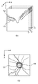
次に、図3を用いて、図2に示す検出部14aにおける特定部位の検出の仕方の概要について説明する。図3には、OCTにより撮像された視神経乳頭部の断層像及び投影像の一例が示される。 Next, an outline of how to detect a specific part in the detection unit 14a shown in FIG. 2 will be described with reference to FIG. FIG. 3 shows an example of a tomographic image and a projected image of the optic nerve head imaged by OCT.
ここで、図3(a)には、OCTにより撮像された視神経乳頭部の断層像が示される。T1〜Tnは、視神経乳頭部の2次元断層像(B−scan像)であり、52は、内境界膜であり、51は、網膜色素上皮層の境界である。また、図3(b)には、深度方向(z方向)に断層像の輝度値を積算して作成した投影像が示される。53は、視神経乳頭外縁(Disc)であり、54は、陥凹の外縁(Cup)である。 Here, FIG. 3A shows a tomographic image of the optic papilla imaged by OCT. T1 to Tn are two-dimensional tomographic images (B-scan images) of the optic nerve head, 52 is an inner boundary film, and 51 is a boundary of the retinal pigment epithelium layer. FIG. 3B shows a projection image created by integrating the luminance values of tomographic images in the depth direction (z direction). 53 is an outer edge (Disc) of an optic disc, and 54 is an outer edge (Cup) of a depression.
特定部位の検出に際して、検出部14aは、まず、図3(a)に示す断層像群(断層像T1〜Tn)を位置合わせする。この位置合わせは、例えば、隣接した断層像の類似度を求める評価関数を用いて行なう。この評価関数を用いて算出された値が所定条件を満たすようにして、画像相互間の位置を変化させる。 When detecting the specific part, the detection unit 14a first aligns the tomographic image group (tomographic images T1 to Tn) illustrated in FIG. This alignment is performed using, for example, an evaluation function for obtaining the similarity between adjacent tomographic images. The position between the images is changed so that the value calculated using the evaluation function satisfies a predetermined condition.
次に、検出部14aは、位置合わせした3次元断層像から網膜色素上皮層の境界51を検出する。網膜色素上皮層の境界51は、高輝度な領域となるため、例えば、へシアンフィルタやエッジ検出フィルタを用いて検出すれば良い。
Next, the detection unit 14a detects the
このようにして網膜色素上皮層の境界51を検出し、当該網膜色素上皮層の境界51から視神経乳頭付近の網膜色素上皮層端を検出する。そして、検出した網膜色素上皮層端を3次元領域において連結する。これにより、視神経乳頭外縁(Disc)53が得られる。その後、検出部14aは、その検出結果を記憶部13に格納する。これにより、検出部14aにおける検出処理は終了する。
In this way, the
次に、図4を用いて、図1に示す診断支援装置10における処理の流れの一例について説明する。
Next, an example of the flow of processing in the
診断支援装置10は、第1の取得部11aにおいて、診断対象となる被検眼の3次元の断層像(第1の断層像)を断層像取得装置20又はデータサーバ30から取得する(S101)。また、診断支援装置10は、第2の取得部11bにおいて、比較対象となる被検眼の3次元の断層像(第2の断層像)をデータサーバ30から取得する(S102)。なお、この被検眼の断層像の取得は、被検眼を同定する識別情報(例えば、被験者識別番号)に基づいて行なわれる。
In the first acquisition unit 11a, the
続いて、診断支援装置10は、検出部14aにおいて、第1の断層像及び第2の断層像から特定部位を検出する(S103)。すなわち、網膜色素上皮層の境界を検出し、その検出結果に基づいて乳頭外縁を検出する。そして、診断支援装置10は、対応付け部14bにおいて、当該検出した乳頭外縁を用いて、第1の断層像と第2の断層像とを対応付ける(S104)。
Subsequently, the
ここで、図5を用いて、このS104における対応付け処理について説明する。 Here, the association processing in S104 will be described with reference to FIG.
対応付け処理が開始すると、対応付け部14bは、網膜色素上皮層の境界が存在しない領域として、乳頭境界の内側、及び外側数ピクセル〜数十ピクセルの領域をマスクする。そして、それ以外の領域を用いて、網膜色素上皮層の境界を放物面近似する(S201)。ここで、乳頭境界の外側部分でマスクする領域の大きさは、乳頭の大きさに依存し、例えば、乳頭の長径の10分の1とする。 When the associating process starts, the associating unit 14b masks an area of several pixels to several tens of pixels inside and outside the nipple boundary as an area where the boundary of the retinal pigment epithelium layer does not exist. Then, the boundary of the retinal pigment epithelium layer is parabolically approximated using other regions (S201). Here, the size of the area masked by the outer portion of the nipple boundary depends on the size of the nipple and is, for example, 1/10 of the major axis of the nipple.
3次元空間内で放物面近似を行なう場合、そのパラメータとしては、原点の座標(x0、y0、z0)と、回転(Θ、φ、ψ)と、放物面の曲率を示す(k1、k2)とが挙げられる。上述した通り、第1の断層像及び第2の断層像は、異なる時期に撮像されているため、撮像パラメタの違いや目の動きなどの影響により、原点の座標や回転が異なっている可能性が高い。それに対して、曲率は、緑内障の進行に伴って眼球の構造が大きく変化することはないため、第1の断層像と第2の断層像とでほぼ同一の値となる。 When parabolic approximation is performed in a three-dimensional space, the parameters include the coordinates of the origin (x 0 , y 0 , z 0 ), rotation (Θ, φ, ψ), and the curvature of the paraboloid. (K 1 , k 2 ). As described above, since the first tomographic image and the second tomographic image are taken at different times, the coordinates and rotation of the origin may be different due to the influence of the difference in the imaging parameters and the movement of the eyes. Is expensive. On the other hand, the curvature has almost the same value in the first tomographic image and the second tomographic image because the structure of the eyeball does not change greatly with the progress of glaucoma.
そこで、対応付け部14bは、まず、第1の断層像(診断対象となる被検眼の断層像)で放物面近似を行なった後、第2の断層像(比較対象となる被検眼の断層像)に対しては原点の座標と回転とを近似により求める。曲率は、第1の断層像から求めた値と同一とする。なお、処理の順番は特に問わず、例えば、第2の断層像(比較眼)から曲率を求め、第1の断層像(対象眼)からは原点の座用や回転のみを求めるようにしても良い。また、近似曲面の算出の仕方も、このような手法に限定されず、例えば、thin−plate splineなどを用いて、より複雑な形状を近似するようにしても良い。 Therefore, the associating unit 14b first performs parabolic surface approximation on the first tomographic image (the tomographic image of the eye to be examined as a diagnosis target), and then the second tomographic image (the tomographic image of the eye to be examined as a comparison target). For the image, the coordinates and rotation of the origin are obtained by approximation. The curvature is the same as the value obtained from the first tomographic image. The order of processing is not particularly limited. For example, the curvature is obtained from the second tomographic image (comparison eye), and only the origin or rotation is obtained from the first tomographic image (target eye). good. Further, the method of calculating the approximate curved surface is not limited to such a method. For example, a more complicated shape may be approximated using thin-plate spline or the like.
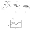
次に、対応付け部14bは、S201で求めた放物面に基づいて、網膜色素上皮層の境界が水平となるように3次元断層像を変形させる(S202)。この変形は、アフィン変換によって放物面(S201で求めた近似的網膜色素上皮の境界)の頂点を原点に変換し、回転軸をz軸に一致させることにより行なえば良い。なお、本実施形態においては、説明の便宜上、第1の断層像及び第2の断層像の撮像時における拡大率や解像度は同一であるものとして説明するが、両断層像における撮像時の設定が異なっていても良い。この場合、両断層像における拡大率や解像度の相違を考慮して座標変換等を行なえば良い。また、回転軸の周りの回転ψに関しては、断層像の撮像方向をx軸としている(図6(a)〜(c)参照)。 Next, the associating unit 14b deforms the three-dimensional tomographic image based on the paraboloid obtained in S201 so that the boundary of the retinal pigment epithelium layer is horizontal (S202). This deformation may be performed by converting the apex of the paraboloid (the boundary of the approximate retinal pigment epithelium obtained in S201) to the origin by affine transformation and making the rotation axis coincide with the z axis. In this embodiment, for convenience of explanation, it is assumed that the magnification and resolution at the time of capturing the first tomographic image and the second tomographic image are the same, but the settings at the time of capturing both tomographic images are the same. It may be different. In this case, coordinate conversion or the like may be performed in consideration of the difference in magnification and resolution between the two tomographic images. Regarding the rotation ψ around the rotation axis, the imaging direction of the tomographic image is the x-axis (see FIGS. 6A to 6C).
次に、対応付け部14bは、放物面の位置がx−y平面上にくるように、方物面をz方向に移動させる。これにより、網膜色素上皮の境界51の近似放物面を水平にすべく変形させる(図6(d)参照)。
Next, the associating unit 14b moves the paraboloid in the z direction so that the position of the paraboloid is on the xy plane. As a result, the approximate paraboloid of the
具体的には、図6(c)の状態となった近似放物面は、「式1」のように表せる。
z=f(x,y)=ax2+bxy+cy2 (式1)
Specifically, the approximate paraboloid in the state of FIG. 6C can be expressed as “Expression 1”.
z = f (x, y) = ax 2 + bxy + cy 2 (Formula 1)
そして、各ピクセルの値を「式2」のように変更する。
I(x,y,z)=IORG(x,y,z+f(x,y)) (式2)
これにより、近似放物面上のピクセルはx−y平面上に移動し、その結果、全てのピクセル値がz方向に移動する。このようにして図6(d)に示す断層像が得られる。
Then, the value of each pixel is changed as shown in “Expression 2”.
I (x, y, z) = I ORG (x, y, z + f (x, y)) (Formula 2)
This causes pixels on the approximate paraboloid to move on the xy plane, and as a result, all pixel values move in the z direction. In this way, a tomographic image shown in FIG. 6D is obtained.
続いて、対応付け部14bは、S202で求めた変形画像に基づいて、第1の断層像(対象眼)と第2の断層像(比較眼)とを重ね合わせる(S203)。より具体的には、乳頭外縁をx−y平面上に投影し、3次元空間内で検出された乳頭外縁を2次元平面上の形状に変換する。そして、図7に示すように、原点(x0、y0、z0)を中心として、第2の断層像(比較眼)をx−y平面内で回転させる。これにより、x−y平面上に投影された投影像各々における乳頭外縁の形状が所定条件を満たすよう(略一致するよう)に重ね合わせる。 Subsequently, the associating unit 14b superimposes the first tomographic image (target eye) and the second tomographic image (comparison eye) based on the deformed image obtained in S202 (S203). More specifically, the nipple outer edge is projected on the xy plane, and the nipple outer edge detected in the three-dimensional space is converted into a shape on the two-dimensional plane. Then, as shown in FIG. 7, the second tomographic image (comparative eye) is rotated in the xy plane around the origin (x 0 , y 0 , z 0 ). Thereby, the shape of the outer edge of the nipple in each projected image projected on the xy plane is overlaid so as to satisfy a predetermined condition (substantially match).
ここで、この重ね合わせ処理では、x−y平面上に投影された第1の断層像及び第2の断層像における乳頭外縁上に所定間隔でコントロールポイント(制御点)を設定する。そして、第1の断層像及び第2の断層像の対応する制御点間の距離の総和(2乗和)を求める。このとき、第2の断層像(比較眼)を第1の断層像(対象眼)に対してx−y平面上で回転させつつ、対応する制御点間における距離の2乗和が最小となる回転角度を求める。このようにして第1の断層像(対象眼)の乳頭外縁に対して第2の断層像(比較眼)の乳頭外縁を対応付ける。 Here, in this superimposition process, control points (control points) are set at predetermined intervals on the outer edge of the nipple in the first tomographic image and the second tomographic image projected on the xy plane. Then, the sum (square sum) of the distances between the corresponding control points of the first tomographic image and the second tomographic image is obtained. At this time, while the second tomographic image (comparison eye) is rotated on the xy plane with respect to the first tomographic image (target eye), the sum of squares of the distances between the corresponding control points is minimized. Find the rotation angle. In this manner, the nipple outer edge of the second tomogram (comparative eye) is associated with the nipple outer edge of the first tomogram (target eye).
なお、制御点の設定は、検出された乳頭外縁部の形状に基づいて行なう。具体的には、乳頭外縁部となる閉曲面上で、最も距離が長くなる2点を選択し、その2点のうち、より上部(顔の上部)にある点を開始点(C1)として、所定間隔にN点設定する(C1〜CN)。この場合、第1の断層像と第2の断層像とで乳頭外縁部の形状に大きな変化がないと考えられる場合には、それぞれ番号が一致する制御点が対応する制御点となる。この他にも、乳頭外縁部の形状で特徴的な形状が見られる場合には、その点を検出してその点を制御点の開始点(C1)とする方法もある。この場合にも、対応する制御点は、番号が一致する制御点同士となる。 The control point is set based on the detected shape of the outer edge of the nipple. Specifically, on the closed curved surface that becomes the outer edge of the nipple, two points that have the longest distance are selected, and the point that is higher above (upper part of the face) of the two points is used as the start point (C1). N points are set at predetermined intervals (C1 to CN). In this case, when it is considered that there is no significant change in the shape of the outer edge of the nipple between the first tomographic image and the second tomographic image, the control points having the same numbers are the corresponding control points. In addition to this, when a characteristic shape is seen in the shape of the outer edge of the nipple, there is a method of detecting the point and setting that point as the start point (C1) of the control point. Also in this case, the corresponding control points are control points having the same number.
重ね合わせ処理が済むと、対応付け部14bは、その対応付け結果を評価する(S204)。具体的には、S203の処理で乳頭外縁上に設定した制御点間における距離の2乗和(の最小値)が所定値(閾値)を越えていれば、対応付けが失敗したと判定し、当該制御点間における距離の2乗和が閾値の範囲内に収まっていれば、対応付けが成功したと判定する。ここで、閾値は、画像の解像度等に依存して変化するが、制御点間における距離の2乗和を制御点の数で割った値が10程度以下の数になることが望ましいため、それに基づいた値を閾値とすれば良い。つまり、1ピクセルが10μm程度の解像度の画像に対して、対応する制御点間の距離が、平均して10数ピクセル以上となれば、対応付けが失敗した旨の判定を行なう。 When the superimposition process is completed, the associating unit 14b evaluates the associating result (S204). Specifically, if the sum of squares (the minimum value) of the distances between the control points set on the outer edge of the nipple in S203 exceeds a predetermined value (threshold value), it is determined that the association has failed, If the sum of squares of the distances between the control points is within the threshold range, it is determined that the association is successful. Here, the threshold value varies depending on the resolution of the image and the like, but it is desirable that the value obtained by dividing the sum of squares of the distances between the control points by the number of control points is about 10 or less. A value based on the threshold may be used as a threshold value. That is, for an image having a resolution of about 10 μm per pixel, if the distance between corresponding control points is an average of 10 or more pixels, it is determined that the association has failed.
このようにして第1の断層像(対象眼)及び第2の断層像(比較眼)それぞれから検出した乳頭外縁を互いに対応付け、その対応付け結果を評価した後、この対応付け処理(図5に示す処理)は終了する。なお、記憶部13には、対応付けの結果として、網膜神経線維層境界の近似放物面を表すパラメータ群、対応付けされた乳頭外縁、断層像それぞれの乳頭外縁上に設定された制御点の対応関係等の情報が格納される。
The nipple outer edges detected from the first tomographic image (target eye) and the second tomographic image (comparing eye) are associated with each other in this way, and the association result is evaluated, and then this association process (FIG. 5) is performed. The processing shown in FIG. In addition, as a result of the association, the
図4の説明に戻り、対応付け処理が終わると、診断支援装置10は、対応付け部14bにおいて、上述した対応付け処理が成功したか否かの判定を行なう。すなわち、対応付け結果を示す値(対応する制御点間における距離の2乗和)が所定値(閾値)の範囲内に収まっているか否かを判定する。
Returning to the description of FIG. 4, when the association process is completed, the
判定の結果、対応付けが失敗したと判定した場合(S105でNO)、診断支援装置10は、表示制御部14dにおいて、その旨を表示部15に表示する(S108)。対応付けが失敗した場合、第1の断層像と第2の断層像とにおける乳頭外縁の形状が大きく変化している可能性が高いため、網膜の疾患の進行状態に関するアラートを表示しても良い。例えば、緑内障以外の疾患を併発している可能性がある旨をアラートとして表示する。
As a result of the determination, if it is determined that the association has failed (NO in S105), the
一方、対応付けが成功したと判定した場合(S105でYES)、診断支援装置10は、再構成部14cにおいて、断層像を再構成する方向を決定し、その方向に従って2次元の断層像を作成する。より具体的には、3次元断層像内における乳頭外縁から図5のS201で求めた近似放物面の回転軸の方向に向けて2次元の断層像を作成(再構成)する。これにより、第1の断層像に基づく2次元の断層像と、第2の断層像に基づく2次元の断層像とがそれぞれ作成される。なお、断層像を作成する際、撮像時に取得されていない座標に位置する画像に関しては、例えば、バイキュービック法による画像補間を行なえば良い。
On the other hand, when it is determined that the association is successful (YES in S105), the
2次元断層像の再構成が済むと、診断支援装置10は、表示制御部14dにおいて、再構成された2次元の断層像に基づいて表示用の画像を作成する(S106)。ここでは、オペレータ(医師)が、緑内障の進行に伴って大きく変化する特徴を容易に把握できるべく、表示用の画像を作成する必要がある。
When the reconstruction of the two-dimensional tomographic image is completed, the
その後、診断支援装置10は、表示制御部14dにおいて、当該作成した表示用の画像に基づいて2次元の断層像を並べた表示画面を表示部15に向けて表示する(S107)。なお、この再構成結果等は、適宜、記憶部13に格納されたり、また、出力部16によりデータサーバ30に格納されたりする。
After that, the
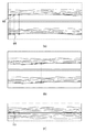
次に、図8を用いて、図4のS107において表示される画面の一例について説明する。 Next, an example of the screen displayed in S107 of FIG. 4 will be described using FIG.
表示画面の一例としては、図8(a)に示すように、第1の断層像に基づいて再構成された2次元断層像と、第2の断層像に基づいて再構成された2次元断層像とを並べて表示する。このとき、2次元断層像各々は、対応付け処理(図4のS104)で各3次元断層像の乳頭外縁上に設定された制御点65によりそれぞれ対応付けられている。すなわち、2次元断層像各々における乳頭外縁の各部が互いに対応付けられている。このように対応する制御点同士の図中横方向(乳頭外縁)の位置を一致させることで、断層像間で変化している特徴を際立たせることができる。
As an example of the display screen, as shown in FIG. 8A, a two-dimensional tomographic image reconstructed based on the first tomographic image and a two-dimensional tomographic image reconstructed based on the second tomographic image. Display images side by side. At this time, each two-dimensional tomographic image is associated with each other by the
また、乳頭の大きさは、個人によりかなりのばらつきがあることが知られている。そして、その大きさの違いに起因して診断に際して注意すべき所見も異なってくる。そのため例えば、乳頭外縁の円周の長さに応じて2次元断層像の表示領域の幅を変化させても良い。これにより、診断を行なうオペレータ(医師)に乳頭外縁の大きさの違いを直感的に示すことができる。 It is also known that the size of the nipple varies considerably from individual to individual. And the findings that should be noted in diagnosis differ due to the difference in size. Therefore, for example, the width of the display area of the two-dimensional tomographic image may be changed according to the circumferential length of the outer edge of the nipple. Thereby, it is possible to intuitively show the difference in the size of the outer edge of the teat to the operator (doctor) who performs the diagnosis.
また、乳頭外縁は、乳頭を囲む円に近い連続的な閉曲線で構成される。図8(a)では、当該閉曲線の円周に沿った断面図が示されている。そのため、オペレータの指示(マウス操作)により、当該閉曲線の内、どの位置を開始点(図中の左端)とするかを指定できるようにしても良い。オペレータが、例えば、マウスをクリックした状態で右にスクロールした場合、図8(b)に示すように、2次元断層像の表示を右にスライドさせても良い。 The outer edge of the nipple is composed of a continuous closed curve close to a circle surrounding the nipple. FIG. 8A shows a cross-sectional view along the circumference of the closed curve. Therefore, it may be possible to designate which position of the closed curve is the start point (the left end in the figure) according to the operator's instruction (mouse operation). For example, when the operator scrolls to the right while clicking the mouse, the display of the two-dimensional tomographic image may be slid to the right as shown in FIG.
また、緑内障の疾患の進行状況を把握するには、網膜の層構造の変化が重要となる。その変化をオペレータに対して明示的に提示するには、網膜色素上皮の下方(脈絡膜側)の画像は排除し、網膜の情報のみを示すことも考えられる。 In order to grasp the progress of glaucoma disease, changes in the layer structure of the retina are important. In order to explicitly present the change to the operator, it is also possible to exclude the image below the retinal pigment epithelium (choroid side) and show only information on the retina.
そのため、図8(c)に示すように、網膜色素上皮境界の上部のみを向かい合わせて表示するようにしても良い。この場合、図8(a)に示す網膜色素上皮の境界を直線化した後、いずれか一方の画像を上下反転させている。これにより、オペレータ(医師)に対して、網膜層の変化をより明確に提示することができる。 Therefore, as shown in FIG. 8C, only the upper part of the retinal pigment epithelium boundary may be displayed facing each other. In this case, after linearizing the boundary of the retinal pigment epithelium shown in FIG. 8A, one of the images is turned upside down. Thereby, the change of the retinal layer can be presented more clearly to the operator (doctor).
以上説明したように実施形態1によれば、第1の断層像及び第2の断層像内における特定部位(疾患の進行に伴う変化の少ない解剖学的な構造)を用いて、両断層像の対応付けを行なう。そして、当該対応付けた両断層像における同一の位置(対応する位置)で所定方向に沿って2次元断層像を再構成し、それをオペレータに向けて表示する。これにより、医師(オペレータ)は、乳頭周辺における網膜神経線維層の減退の程度を的確に把握できることになる。 As described above, according to the first embodiment, the tomographic images of the two tomographic images are obtained by using a specific portion (anatomical structure with little change as the disease progresses) in the first tomographic image and the second tomographic image. Make the association. Then, a two-dimensional tomographic image is reconstructed along a predetermined direction at the same position (corresponding position) in both of the correlated tomographic images, and displayed to the operator. Thereby, the doctor (operator) can grasp | ascertain exactly the grade of the fall of the retinal nerve fiber layer around a nipple.
なお、上述した図5のS203に示す重ね合わせ処理では、第1の断層像及び第2の断層像における乳頭外縁を2次元平面上に投影し、その投影像における乳頭外縁上に設定した制御点に基づいて断層像同士を対応付けていたが、これ以外の手法を用いても良い。 In the superimposing process shown in S203 of FIG. 5 described above, the control point set on the nipple outer edge in the projection image is projected on the two-dimensional plane by projecting the nipple outer edge in the first tomographic image and the second tomographic image. However, other methods may be used.
例えば、変形画像から各ピクセルの積算値をz軸方向に求めることにより、x−y平面上に投影像を作成することもできる。この場合、第1の断層像及び第2の断層像の投影像同士が(最も)高い類似度で重なる相対位置を求め、両断層像における乳頭外縁を対応付ける。なお、この手法では、積算するピクセル数を統一する必要がある。そのため、変形画像の作成時に撮像領域外にピクセルがはみ出した場合には、有効であるピクセルのみで構成されるx−y平面を含む直方体の中でピクセルの積算値を求めれば良い。また、類似度の算出は、一般的に用いられている手法を用いれば良い。例えば、画像を2値化し、その値が一致するピクセル数が最大となるように重ね合わせを行なう等の方法が挙げられる。この場合、網膜色素上皮層よりも上側(内境界膜側)にある血管などの特徴を一致させることになる。但し、投影像を積算する方向が3次元画像のz軸と大きく異なっていれば、撮像の際にできる血管の影の影響が他の部分へ影響を与える可能性がある。これは、重ね合わせ時の誤差の原因となるが、血管領域を予め抽出し、血管の影の影響を受ける投影像内の領域をマスクして類似度を評価することにより影響を小さくできる。 For example, a projection image can be created on the xy plane by obtaining the integrated value of each pixel in the z-axis direction from the deformed image. In this case, a relative position where the projection images of the first tomographic image and the second tomographic image overlap with each other with the (highest) similarity is obtained, and the nipple outer edge in both tomographic images is associated. In this method, it is necessary to unify the number of pixels to be integrated. For this reason, if a pixel protrudes outside the imaging region when creating a deformed image, the integrated value of the pixel may be obtained in a rectangular parallelepiped including an xy plane composed only of valid pixels. The similarity may be calculated using a generally used method. For example, there is a method of binarizing an image and performing superposition so that the number of pixels with the same value is maximized. In this case, features such as blood vessels on the upper side (inner boundary membrane side) of the retinal pigment epithelium layer are matched. However, if the direction in which the projected images are integrated is significantly different from the z-axis of the three-dimensional image, there is a possibility that the influence of the shadow of the blood vessel formed at the time of imaging affects other parts. This causes an error at the time of superimposition, but the influence can be reduced by extracting the blood vessel region in advance and masking the region in the projection image affected by the shadow of the blood vessel to evaluate the similarity.
また、緑内障の進行に伴う網膜層の減退により、網膜色素上皮層より上方の特徴量が、過去に撮像された画像と比べて大きな変化が生じていることも予測される。特に、視神経乳頭付近ではその傾向が良く見られる。このような変化により対応付け処理が影響を受けることを抑制するため、網膜色素上皮層付近及びその下方のみに存在する特徴量を用いて、第1の断層像及び第2の断層像が最も高い類似度で重なる相対位置を求めるようにしても良い。この場合、類似度の評価は、上記同様に投影像を作成して2次元平面上で行っても良いし、3次元のボリュームのままで行なっても良い。また、変化の大きな領域を除くために乳頭周囲外側の数ピクセル〜数十ピクセルより内側をマスクするとともに、血管の影の影響を受ける投影像内の領域をマスクするようにしても良い。これにより、精度の高い重ね合わせが行なえる。 It is also predicted that the feature amount above the retinal pigment epithelium layer is greatly changed compared to previously captured images due to the decrease in the retinal layer accompanying the progression of glaucoma. This tendency is particularly seen near the optic disc. In order to suppress the influence of the association processing due to such a change, the first tomographic image and the second tomographic image are the highest using the feature quantity existing only near and below the retinal pigment epithelium layer. You may make it obtain | require the relative position which overlaps with a similarity degree. In this case, the similarity evaluation may be performed on a two-dimensional plane by creating a projection image in the same manner as described above, or may be performed with a three-dimensional volume. Further, in order to exclude a region having a large change, the inner side of the outer periphery of the nipple from several pixels to several tens of pixels may be masked, and the region in the projection image affected by the shadow of the blood vessel may be masked. Thereby, it is possible to perform superposition with high accuracy.
また更に、上記以外の手法を用いた対応付け処理としては、例えば、視神経乳頭の境界に重きをおいて対応付けを行なう方法や、射影面を乳頭境界の検出点から近似的に求める方法なども挙げられる。なお、上述した本実施形態に係わる手法では、これらの手法に比べて、第1の断層像及び第2の断層像において視神経乳頭の位置や向きが大きく異なっていたとしても、有効な手段であるといえる。 Further, as the association processing using a method other than the above, for example, there is a method of performing an association with emphasis on the boundary of the optic nerve head or a method of approximately obtaining the projection plane from the detection point of the nipple boundary. Can be mentioned. Note that the method according to the present embodiment described above is an effective means even if the position and orientation of the optic disc are greatly different in the first tomographic image and the second tomographic image as compared with these methods. It can be said.
(実施形態2)
次に、実施形態2について説明する。実施形態1においては、経過観察において異なる時期に撮像された同一の被検眼同士を比較する場合を例に挙げて説明した。これに対して、実施形態2においては、同一被験者の左右両眼を比較する場合について説明する。これは、同一被験者の左右両眼では、視神経乳頭の大きさのばらつきが小さいためである。視神経乳頭の大きさは、人によるばらつきが大きいことが知られているが、同一人物の左右の目においてはそのばらつきが小さい(99%の人で左右の乳頭の大きさは、1mm〜2mmの差との報告もある)。
(Embodiment 2)
Next, Embodiment 2 will be described. In Embodiment 1, the case where the same eye to be examined imaged at different times in follow-up observation is compared is described as an example. On the other hand, in Embodiment 2, the case where the left and right eyes of the same subject are compared will be described. This is because there is little variation in the size of the optic disc between the left and right eyes of the same subject. It is known that the size of the optic nerve head varies greatly among people, but the variation is small in the left and right eyes of the same person (99% of people have a size of 1 to 2 mm on the left and right nipples). There are also reports of differences).
ここで、実施形態2においては、乳頭境界の形状に着目して断層像の対応付けを行なう。実施形態1との相違点としては、図4のS104に示す対応付け処理にある。なお、装置構成や対応付け以外の処理については、実施形態1と同様であるため、ここでは、その説明については省略する。 Here, in the second embodiment, the tomographic image is associated by paying attention to the shape of the nipple boundary. The difference from the first embodiment is the association process shown in S104 of FIG. Since processing other than the device configuration and association is the same as that in the first embodiment, the description thereof is omitted here.
乳頭外縁の形状は、上下に長い楕円で近似される形状をしている。ここで、実施形態1における図4のS103のように、3次元断層像(第1の断層像及び第2の断層像)から検出した場合には、乳頭外縁の形状は、3次元空間内の閉曲線となる。乳頭の大きさが左右で大きくばらつかないことを考慮すれば、両眼から検出される乳頭外縁は、それぞれ同様の形状を有した閉曲線として検出される。この場合、検出される乳頭外縁は、3次元空間内で位置及び向きが異なっている場合が多い。ここで、位置及び向きが異なる場合が多いとしたが、これは、目の動きや撮像パラメータの差を考慮したためである。 The shape of the outer edge of the nipple is a shape approximated by a long ellipse vertically. Here, when detected from a three-dimensional tomogram (first tomogram and second tomogram) as in S103 of FIG. 4 in the first embodiment, the shape of the outer edge of the nipple is within the three-dimensional space. It becomes a closed curve. Considering that the size of the nipple does not vary greatly from side to side, the nipple outer edge detected from both eyes is detected as a closed curve having the same shape. In this case, the detected nipple outer edge is often different in position and orientation in the three-dimensional space. Here, it is assumed that the position and orientation are often different, but this is because the difference in eye movement and imaging parameters is taken into consideration.
ここで、検出された乳頭外縁を2次元の閉曲線として近似できるのであれば、その平面上に投影像をつくることが望ましい。左眼、右眼それぞれに対して、各乳頭外縁の検出点の近似平面からの距離の総和が最も小さくなるように、乳頭外縁の近似平面を求める。こうして求められた近似平面上に3次元断層像の投影像を作成し、当該投影された乳頭外縁同士の位置合わせを行なう。これにより、対応付けを行なうことができる。 Here, if the detected outer edge of the nipple can be approximated as a two-dimensional closed curve, it is desirable to create a projection image on the plane. For each of the left eye and the right eye, the approximate plane of the nipple outer edge is determined so that the sum of the distances from the approximate plane of the detection points of each nipple outer edge becomes the smallest. A projected image of a three-dimensional tomographic image is created on the approximate plane thus determined, and the projected nipple outer edges are aligned. Thereby, the association can be performed.
より単純化した方法としては、検出された乳頭外縁の検出点の中からいくつかの検出点を選択し、それらを結ぶ線分群に直行する直線を法線ベクトルとして対応付けを行なう方法も考えられる。具体的には、検出点間の距離が最も大きくなる2つの検出点(A,B)と、その2つの検出点を結ぶ線分に略直行する位置にある別の2つの検出点(C,D)を求める。そして、ベクトルABとベクトルCDとの両方に直行するベクトルを法線ベクトルとして求める。投影像は、このベクトルに沿って射影することで求めることができる。 As a simpler method, a method may be considered in which several detection points are selected from the detected points on the outer edge of the nipple and a straight line perpendicular to a line segment connecting them is used as a normal vector. . Specifically, the two detection points (A, B) having the largest distance between the detection points and the other two detection points (C, C) that are substantially perpendicular to the line segment connecting the two detection points. D). Then, a vector orthogonal to both the vector AB and the vector CD is obtained as a normal vector. The projected image can be obtained by projecting along this vector.
この場合、2次元断層像を再構成する方向は、任意の方向を選択しても良い。例えば、2次元平面上で位置合わせを行なった場合には、3次元から2次元の投影像を作成する際の射影方向を再構成の方向にすれば良い。また、例えば、3次元空間で位置合わせを行なった場合には、乳頭外縁に対する近似閉曲面に直行する方向を再構成の方向にすれば良い。 In this case, an arbitrary direction may be selected as the direction for reconstructing the two-dimensional tomographic image. For example, when alignment is performed on a two-dimensional plane, the projection direction when generating a three-dimensional to two-dimensional projection image may be set as a reconstruction direction. For example, when alignment is performed in a three-dimensional space, the direction orthogonal to the approximate closed curved surface with respect to the outer edge of the nipple may be set as the direction of reconstruction.
以上説明したように実施形態2によれば、同一人物の左右両眼からそれぞれ撮像された3次元の断層像を対応付け、両断層像における対応する位置の2次元断層像を再構成する。これにより、片眼のみ緑内障が発生していたり、また、左右両眼で緑内障の進行が異なったりしている場合にも、オペレータ(医師)に対してその差異を明確に提示できる。 As described above, according to the second embodiment, the three-dimensional tomographic images captured from the left and right eyes of the same person are associated with each other, and the two-dimensional tomographic images at the corresponding positions in both tomographic images are reconstructed. Thereby, even when glaucoma occurs only in one eye or the progression of glaucoma differs between the left and right eyes, the difference can be clearly presented to the operator (doctor).
(実施形態3)
次に、実施形態3について説明する。実施形態3においては、比較を行なう断層像同士を加工し、それにより、断層像間における差異を明確にしてオペレータに提示する場合について説明する。より具体的には、比較を行なう断層像の表示に際して、差分処理を実施し、それにより、両断層像の差異をオペレータに向けて表示する。ここで、実施形態1及び2との相違点としては、図4のS107に示す表示制御処理にある。なお、装置構成や表示制御以外の処理については、実施形態1及び2と同様であるため、ここでは、その説明については省略する。
(Embodiment 3)
Next, Embodiment 3 will be described. In the third embodiment, a case will be described in which tomographic images to be compared are processed so that differences between the tomographic images are clarified and presented to the operator. More specifically, when displaying the tomographic images to be compared, a difference process is performed, whereby the difference between the two tomographic images is displayed to the operator. Here, the difference from Embodiments 1 and 2 is the display control process shown in S107 of FIG. Since processing other than the device configuration and display control is the same as in the first and second embodiments, the description thereof is omitted here.
ここで、差分画像は、例えば、第1の断層像における各ピクセルの輝度値から、第2の断層像における対応するピクセルの輝度値を差し引いて作成すれば良い。また、これとは逆に、第2の断層像における各ピクセルの輝度値から第1の断層像における対応するピクセルの輝度値を差し引いて作成しても良い。 Here, for example, the difference image may be created by subtracting the luminance value of the corresponding pixel in the second tomographic image from the luminance value of each pixel in the first tomographic image. Conversely, the brightness value of each pixel in the second tomogram may be subtracted from the brightness value of the corresponding pixel in the first tomogram.
ここで、差分画像の表示態様の一例について説明する。例えば、図8(a)に示す態様で表示すれば良い。例えば、上側の領域には、診断対象となる断層像(第1の断層像に基づく2次元の断層像)を表示し、下側の領域には、差分画像を表示する。なお、表示態様については、これに限られない。診断対象の断層像と差分画像とが同一画面上に表示され、両画像の比較を容易にできるのであれば、特にその方法は問わない。 Here, an example of the display mode of the difference image will be described. For example, what is necessary is just to display in the aspect shown to Fig.8 (a). For example, a tomographic image to be diagnosed (a two-dimensional tomographic image based on the first tomographic image) is displayed in the upper region, and a difference image is displayed in the lower region. The display mode is not limited to this. The method is not particularly limited as long as the tomographic image to be diagnosed and the difference image are displayed on the same screen and the two images can be easily compared.
以上説明したように実施形態3によれば、第1の断層像と第2の断層像との差分を求め、両断層像の差異をオペレータに向けて表示する。この場合にも上記同様の効果が得られる。 As described above, according to the third embodiment, the difference between the first tomographic image and the second tomographic image is obtained, and the difference between the two tomographic images is displayed to the operator. In this case, the same effect as described above can be obtained.
以上が本発明の代表的な実施形態の一例であるが、本発明は、上記及び図面に示す実施形態に限定することなく、その要旨を変更しない範囲内で適宜変形して実施できるものである。 The above is an example of a typical embodiment of the present invention, but the present invention is not limited to the embodiment described above and shown in the drawings, and can be appropriately modified and implemented without departing from the scope of the present invention. .
(その他の実施形態)
本発明は、以下の処理を実行することによっても実現される。即ち、上述した実施形態の機能を実現するソフトウェア(プログラム)を、ネットワーク又は各種記憶媒体を介してシステム或いは装置に供給し、そのシステム或いは装置のコンピュータ(又はCPUやMPU等)がプログラムを読み出して実行する処理である。
(Other embodiments)
The present invention is also realized by executing the following processing. That is, software (program) that realizes the functions of the above-described embodiments is supplied to a system or apparatus via a network or various storage media, and a computer (or CPU, MPU, etc.) of the system or apparatus reads the program. It is a process to be executed.
Claims (11)
前記第1の3次元断層像と前記第2の3次元断層像とのそれぞれに含まれる前記被検眼の視神経乳頭に基づいて前記第1の3次元断層像と前記第2の3次元断層像とを位置合わせする位置合わせ手段と、
前記位置合わせの正否を判定する判定手段と、
前記判定手段により前記位置合わせが失敗したと判定された場合、前記被検眼の疾患の状態に関するアラートを表示手段に表示させる表示制御手段と、
を備えることを特徴とする眼科装置。 Obtaining means for obtaining a first three-dimensional tomographic image and a second three-dimensional tomographic image of the fundus of the eye to be examined;
The first three-dimensional tomogram and the second three-dimensional tomogram based on the optic nerve head of the eye to be examined included in each of the first three-dimensional tomogram and the second three-dimensional tomogram Alignment means for aligning,
Determining means for determining whether the alignment is correct;
A display control means for displaying on the display means an alert related to the disease state of the eye to be examined, when the determination means determines that the alignment has failed;
An ophthalmologic apparatus comprising:
前記第1の3次元断層像に基づく投影像と前記第2の3次元断層像に基づく投影像とにおける対応する前記制御点間の距離の2乗和を算出する算出手段と、を更に備え、
前記判定手段は、前記算出手段により算出された前記2乗和の最小値が所定の閾値に収まった場合、前記位置合わせが成功したと判定し、前記2乗和の最小値が前記所定の閾値を超過した場合、前記位置合わせに失敗したと判定する
ことを特徴とする請求項1または2に記載の眼科装置。 Setting means for setting control points at predetermined intervals with respect to the optic disc on a projection image obtained by projecting the first three-dimensional tomogram and the second three-dimensional tomogram on a two-dimensional plane, respectively. When,
Further comprising a calculating means for calculating a sum of squares of distances between the control points corresponding in the projected image based on the first said a projection image based on the three-dimensional tomographic image of the second three-dimensional tomographic image,
The determination unit determines that the alignment is successful when the minimum value of the square sum calculated by the calculation unit falls within a predetermined threshold value, and the minimum value of the square sum is determined by the predetermined threshold value. exceeded, it determined to have failed the alignment
Ophthalmologic apparatus according to claim 1 or 2, characterized and this.
前記疾患の状態に関するアラートとして緑内障以外の疾患を発症している可能性を示すアラートを前記表示手段に表示させることを特徴とする請求項1乃至3のいずれか1項に記載の眼科装置。 The display control means includes
The ophthalmic apparatus according to any one of claims 1 to 3, wherein an alert indicating a possibility of developing a disease other than glaucoma is displayed on the display unit as an alert related to the disease state .
前記取得手段が、被検眼の眼底の第1の3次元断層像及び第2の3次元断層像を取得する取得工程と、
前記位置合わせ手段が、前記第1の3次元断層像と前記第2の3次元断層像とのそれぞれに含まれる前記被検眼の視神経乳頭に基づいて前記第1の3次元断層像と前記第2の3次元断層像とを位置合わせする位置合わせ工程と、
前記判定手段が、前記位置合わせの正否を判定する判定工程と、
前記表示制御手段が、前記判定工程により前記位置合わせが失敗したと判定された場合、前記被検眼の疾患の状態に関するアラートを表示手段に表示させる表示制御工程と、
を有することを特徴とする眼科装置の表示制御方法。 A display control method for an ophthalmologic apparatus comprising an acquisition means, an alignment means, a determination means, and a display control means,
An acquisition step in which the acquisition means acquires a first three-dimensional tomographic image and a second three-dimensional tomographic image of the fundus of the eye;
The positioning means includes the first 3D tomographic image and the second 3D tomographic image based on the optic nerve head of the eye to be examined included in each of the first 3D tomographic image and the second 3D tomographic image. An alignment step of aligning the three-dimensional tomographic image of
A determination step in which the determination unit determines whether the alignment is correct;
When the display control means determines that the alignment has failed in the determination step, a display control step for displaying an alert on the disease state of the eye to be examined on the display means;
A display control method for an ophthalmologic apparatus, comprising:
前記第1の画像と前記第2の画像とのそれぞれに含まれる前記被検眼の視神経乳頭に基づいて前記第1の画像と前記第2の画像とを位置合わせする位置合わせ手段と、Alignment means for aligning the first image and the second image based on the optic disc of the eye to be examined included in each of the first image and the second image;
前記位置合わせの正否を判定する判定手段と、Determining means for determining whether the alignment is correct;
前記判定手段による判定結果に基づいて前記被検眼の疾患の状態に関するアラートを表示手段に表示させる表示制御手段と、Display control means for displaying on the display means an alert relating to the disease state of the eye to be examined based on the determination result by the determination means;
を備えることを特徴とする眼科装置。An ophthalmologic apparatus comprising:
前記疾患の状態に関するアラートとして緑内障以外の疾患を発症している可能性を示すアラートを前記表示手段に表示させる請求項8または9に記載の眼科装置。The ophthalmologic apparatus according to claim 8 or 9, wherein an alert indicating a possibility of developing a disease other than glaucoma is displayed on the display unit as an alert related to the disease state.
Priority Applications (6)
| Application Number | Priority Date | Filing Date | Title |
|---|---|---|---|
| JP2010099066A JP5698465B2 (en) | 2010-04-22 | 2010-04-22 | Ophthalmic apparatus, display control method, and program |
| US13/578,922 US20120330140A1 (en) | 2010-04-22 | 2011-03-09 | Tomogram observation apparatus, processing method, and non-transitory computer-readable storage medium |
| EP11771818A EP2560544A1 (en) | 2010-04-22 | 2011-03-09 | Tomogram observation apparatus, processing method, and non-transitory computer-readable storage medium |
| CN2011800203829A CN102858230A (en) | 2010-04-22 | 2011-03-09 | Tomogram observation apparatus, processing method, and non-transitory computer-readable storage medium |
| PCT/JP2011/056136 WO2011132478A1 (en) | 2010-04-22 | 2011-03-09 | Tomogram observation apparatus, processing method, and non-transitory computer-readable storage medium |
| KR1020127029664A KR20130027506A (en) | 2010-04-22 | 2011-03-09 | Tomogram observation apparatus, processing method, and non-transitory computer-readable storage medium |
Applications Claiming Priority (1)
| Application Number | Priority Date | Filing Date | Title |
|---|---|---|---|
| JP2010099066A JP5698465B2 (en) | 2010-04-22 | 2010-04-22 | Ophthalmic apparatus, display control method, and program |
Publications (3)
| Publication Number | Publication Date |
|---|---|
| JP2011224264A JP2011224264A (en) | 2011-11-10 |
| JP2011224264A5 JP2011224264A5 (en) | 2013-06-06 |
| JP5698465B2 true JP5698465B2 (en) | 2015-04-08 |
Family
ID=44834017
Family Applications (1)
| Application Number | Title | Priority Date | Filing Date |
|---|---|---|---|
| JP2010099066A Expired - Fee Related JP5698465B2 (en) | 2010-04-22 | 2010-04-22 | Ophthalmic apparatus, display control method, and program |
Country Status (6)
| Country | Link |
|---|---|
| US (1) | US20120330140A1 (en) |
| EP (1) | EP2560544A1 (en) |
| JP (1) | JP5698465B2 (en) |
| KR (1) | KR20130027506A (en) |
| CN (1) | CN102858230A (en) |
| WO (1) | WO2011132478A1 (en) |
Families Citing this family (20)
| Publication number | Priority date | Publication date | Assignee | Title |
|---|---|---|---|---|
| JP5955163B2 (en) | 2011-09-06 | 2016-07-20 | キヤノン株式会社 | Image processing apparatus and image processing method |
| AU2011384700B2 (en) * | 2011-12-28 | 2015-09-03 | Alcon Inc. | Process for optical coherence tomography and apparatus for optical coherence tomography |
| JP6188297B2 (en) * | 2012-01-25 | 2017-08-30 | キヤノン株式会社 | Image processing apparatus, image processing method, and program |
| JP6226510B2 (en) | 2012-01-27 | 2017-11-08 | キヤノン株式会社 | Image processing system, processing method, and program |
| JP5996959B2 (en) * | 2012-07-30 | 2016-09-21 | 株式会社トプコン | Fundus analyzer |
| JP6269911B2 (en) | 2012-12-28 | 2018-01-31 | キヤノン株式会社 | Image generating apparatus, image generating method, and ophthalmic apparatus |
| US10497124B2 (en) | 2013-03-15 | 2019-12-03 | Kabushiki Kaisha Topcon | Optic disc image segmentation method and apparatus |
| US9600895B2 (en) * | 2013-05-02 | 2017-03-21 | Saso Koceski | System and method for three-dimensional nerve segmentation using magnetic resonance imaging |
| JP6184232B2 (en) | 2013-07-31 | 2017-08-23 | キヤノン株式会社 | Image processing apparatus and image processing method |
| JP6320051B2 (en) * | 2014-01-17 | 2018-05-09 | キヤノン株式会社 | 3D shape measuring device, 3D shape measuring method |
| JP6812089B2 (en) * | 2015-01-08 | 2021-01-13 | キヤノン株式会社 | Ophthalmic equipment, control methods and programs |
| TWI568408B (en) * | 2015-12-23 | 2017-02-01 | 財團法人工業技術研究院 | Intraocular pressure detecting device and detecting method thereof |
| JP6437055B2 (en) * | 2017-07-14 | 2018-12-12 | キヤノン株式会社 | Image processing apparatus and image processing method |
| US10963737B2 (en) * | 2017-08-01 | 2021-03-30 | Retina-Al Health, Inc. | Systems and methods using weighted-ensemble supervised-learning for automatic detection of ophthalmic disease from images |
| US20190043193A1 (en) * | 2017-08-01 | 2019-02-07 | Retina-Ai Llc | Systems and Methods Using Weighted-Ensemble Supervised-Learning for Automatic Detection of Retinal Disease from Tomograms |
| JP2019042304A (en) * | 2017-09-05 | 2019-03-22 | 株式会社ニデック | Ophthalmological image processing program |
| JP6526145B2 (en) * | 2017-10-06 | 2019-06-05 | キヤノン株式会社 | Image processing system, processing method and program |
| JP6947226B2 (en) * | 2017-12-28 | 2021-10-13 | 株式会社ニコン | Image processing method, image processing program, image processing device, image display device, and image display method |
| JP2019154996A (en) | 2018-03-16 | 2019-09-19 | 株式会社トプコン | Ophthalmologic apparatus and ophthalmologic information processing apparatus |
| WO2023022183A1 (en) * | 2021-08-18 | 2023-02-23 | 株式会社ニコン | Ophthalmic device, control method, and program |
Family Cites Families (11)
| Publication number | Priority date | Publication date | Assignee | Title |
|---|---|---|---|---|
| JPH10234674A (en) * | 1997-02-28 | 1998-09-08 | Nippon Telegr & Teleph Corp <Ntt> | Method for judging presence or absence of change of fundus oculi image with time |
| JP4501007B2 (en) * | 2004-08-26 | 2010-07-14 | 国立大学法人名古屋大学 | Optical coherence tomography device |
| US7869663B2 (en) * | 2005-08-01 | 2011-01-11 | Bioptigen, Inc. | Methods, systems and computer program products for analyzing three dimensional data sets obtained from a sample |
| JP4823204B2 (en) * | 2005-08-31 | 2011-11-24 | 国立大学法人岐阜大学 | Medical image processing device |
| CA2637500A1 (en) * | 2006-01-19 | 2007-07-26 | Optovue, Inc. | A method of eye examination by optical coherence tomography |
| JP4855150B2 (en) * | 2006-06-09 | 2012-01-18 | 株式会社トプコン | Fundus observation apparatus, ophthalmic image processing apparatus, and ophthalmic image processing program |
| JP4854390B2 (en) * | 2006-06-15 | 2012-01-18 | 株式会社トプコン | Spectral fundus measuring apparatus and measuring method thereof |
| JP5085086B2 (en) * | 2006-10-04 | 2012-11-28 | 株式会社トプコン | Fundus observation apparatus, fundus image display apparatus, and program |
| JP5279291B2 (en) * | 2008-02-19 | 2013-09-04 | 株式会社東芝 | Medical image display apparatus and image display method |
| JP2010068865A (en) * | 2008-09-16 | 2010-04-02 | Fujifilm Corp | Diagnostic imaging apparatus |
| WO2011063220A2 (en) * | 2009-11-20 | 2011-05-26 | University Of Pittsburgh - Of The Commonwealth System Of Higher Education | Formalization of retinal nerve fiber layer thickness measurements made by time domain-optical coherence tomography |
-
2010
- 2010-04-22 JP JP2010099066A patent/JP5698465B2/en not_active Expired - Fee Related
-
2011
- 2011-03-09 KR KR1020127029664A patent/KR20130027506A/en active Search and Examination
- 2011-03-09 EP EP11771818A patent/EP2560544A1/en not_active Withdrawn
- 2011-03-09 US US13/578,922 patent/US20120330140A1/en not_active Abandoned
- 2011-03-09 CN CN2011800203829A patent/CN102858230A/en active Pending
- 2011-03-09 WO PCT/JP2011/056136 patent/WO2011132478A1/en active Application Filing
Also Published As
| Publication number | Publication date |
|---|---|
| KR20130027506A (en) | 2013-03-15 |
| JP2011224264A (en) | 2011-11-10 |
| WO2011132478A1 (en) | 2011-10-27 |
| CN102858230A (en) | 2013-01-02 |
| EP2560544A1 (en) | 2013-02-27 |
| US20120330140A1 (en) | 2012-12-27 |
Similar Documents
| Publication | Publication Date | Title |
|---|---|---|
| JP5698465B2 (en) | Ophthalmic apparatus, display control method, and program | |
| US9943224B2 (en) | Image processing apparatus and image processing method | |
| JP5739323B2 (en) | Optical coherence tomography eye registration method | |
| US10383511B2 (en) | Image processing apparatus, image processing method, and program | |
| US8770753B2 (en) | Scanning and processing using optical coherence tomography | |
| US9098742B2 (en) | Image processing apparatus and image processing method | |
| JP5451492B2 (en) | Image processing apparatus, control method thereof, and program | |
| US20110137157A1 (en) | Image processing apparatus and image processing method | |
| JP5952564B2 (en) | Image processing apparatus and image processing method | |
| US9161686B2 (en) | Image processing apparatus and image processing method | |
| JP2018038689A (en) | Ophthalmic photographing apparatus and ophthalmic image processing apparatus | |
| JP5784105B2 (en) | Image processing apparatus and image processing method | |
| JP6033478B2 (en) | Ophthalmic apparatus, layer thickness comparison method and program | |
| JP5017491B2 (en) | Ophthalmic equipment | |
| JP6223527B2 (en) | Ophthalmic apparatus, layer thickness comparison method and program | |
| JP2022038751A (en) | Image processing apparatus, image processing method and program | |
| JP6506518B2 (en) | Ophthalmic apparatus and control method thereof | |
| JP2018020179A (en) | Ophthalmologic apparatus, layer thickness comparison method, and program |
Legal Events
| Date | Code | Title | Description |
|---|---|---|---|
| A521 | Request for written amendment filed |
Free format text: JAPANESE INTERMEDIATE CODE: A523 Effective date: 20130422 |
|
| A621 | Written request for application examination |
Free format text: JAPANESE INTERMEDIATE CODE: A621 Effective date: 20130422 |
|
| A131 | Notification of reasons for refusal |
Free format text: JAPANESE INTERMEDIATE CODE: A131 Effective date: 20140620 |
|
| A521 | Request for written amendment filed |
Free format text: JAPANESE INTERMEDIATE CODE: A523 Effective date: 20140801 |
|
| TRDD | Decision of grant or rejection written | ||
| A01 | Written decision to grant a patent or to grant a registration (utility model) |
Free format text: JAPANESE INTERMEDIATE CODE: A01 Effective date: 20150116 |
|
| A61 | First payment of annual fees (during grant procedure) |
Free format text: JAPANESE INTERMEDIATE CODE: A61 Effective date: 20150213 |
|
| R151 | Written notification of patent or utility model registration |
Ref document number: 5698465 Country of ref document: JP Free format text: JAPANESE INTERMEDIATE CODE: R151 |
|
| LAPS | Cancellation because of no payment of annual fees |