JP5697552B2 - Electromagnetic actuator and electromagnetic relay using the same - Google Patents
Electromagnetic actuator and electromagnetic relay using the same Download PDFInfo
- Publication number
- JP5697552B2 JP5697552B2 JP2011129108A JP2011129108A JP5697552B2 JP 5697552 B2 JP5697552 B2 JP 5697552B2 JP 2011129108 A JP2011129108 A JP 2011129108A JP 2011129108 A JP2011129108 A JP 2011129108A JP 5697552 B2 JP5697552 B2 JP 5697552B2
- Authority
- JP
- Japan
- Prior art keywords
- magnetic
- mover
- magnetic flux
- electromagnetic actuator
- yoke
- Prior art date
- Legal status (The legal status is an assumption and is not a legal conclusion. Google has not performed a legal analysis and makes no representation as to the accuracy of the status listed.)
- Active
Links
- 230000004907 flux Effects 0.000 claims description 76
- 230000005284 excitation Effects 0.000 claims description 35
- 239000000696 magnetic material Substances 0.000 claims description 18
- 238000005457 optimization Methods 0.000 description 6
- 238000003780 insertion Methods 0.000 description 5
- 230000037431 insertion Effects 0.000 description 5
- XEEYBQQBJWHFJM-UHFFFAOYSA-N Iron Chemical compound [Fe] XEEYBQQBJWHFJM-UHFFFAOYSA-N 0.000 description 4
- 238000010586 diagram Methods 0.000 description 4
- 238000005452 bending Methods 0.000 description 2
- 230000000694 effects Effects 0.000 description 2
- 229910052742 iron Inorganic materials 0.000 description 2
- 230000005347 demagnetization Effects 0.000 description 1
- 230000006866 deterioration Effects 0.000 description 1
- 238000000034 method Methods 0.000 description 1
- 230000035699 permeability Effects 0.000 description 1
- 238000004804 winding Methods 0.000 description 1
Images


Landscapes
- Reciprocating, Oscillating Or Vibrating Motors (AREA)
Description
この発明は励磁コイルへの通電の断続により可動子の往復動を行う電磁アクチュエータおよびその電磁アクチュエータを用いた電磁リレーに関するものである。 The present invention relates to an electromagnetic actuator that reciprocates a movable element by energizing an exciting coil, and an electromagnetic relay using the electromagnetic actuator.
従来の例えば電磁リレーなどに使用される電磁アクチュエータは、磁性材からなり相対向する一対の接極片を有するヨークと、磁性材からなり励磁コイルの通電による発生する磁界により駆動されて相対向する接極片に当接する可動子と、可動子に磁界を与える永久磁石とを備え、励磁コイルに流す電流極性により可動子を所要の接極片方向に動作させて可動子を永久磁石により吸引して保持させるように構成されている。(例えば特許文献1第1図参照) Conventional electromagnetic actuators used in, for example, electromagnetic relays are opposed to each other by being driven by a magnetic field made of magnetic material and generated by energization of an excitation coil, and a yoke having a pair of opposing armature pieces made of magnetic material. A mover that abuts the armature piece and a permanent magnet that applies a magnetic field to the mover, and the mover is moved in the direction of the required armature piece by the polarity of the current flowing through the exciting coil, and the mover is attracted by the permanent magnet. Configured to be held. (For example, see FIG. 1 of Patent Document 1)
また同じような電磁アクチュエータとして、図11に示すように、磁性材からなり相対向する一対の接極片を有する第1のヨーク51と、第1のヨーク51の一対の接極片51a、51b間に配置されるボビン(図示省略)に巻装され励磁電流通電時には所望の電磁力を発生する励磁コイル53a、53bと、ボビン内に貫挿された磁性材からなり励磁コイルの磁界により駆動されて往復動され接極片に接触して吸着される可動子55と、第1のヨーク51とボビンとの間に配置され第1のヨーク51に磁束を発生させるとともに可動子55を吸引して保持する永久磁石56と、永久磁石56とともに磁気回路を構成する第2のヨーク57とを備え、接極片51a、51bの可動子55が接触される位置に形成され、永久磁石56により吸引される方向と直交する方向に長い孔からなる当接孔51a1を設けたものもある。(例えば特許文献2 第3図参照)
As a similar electromagnetic actuator, as shown in FIG. 11, a
上下左右対称系の電磁アクチュエータであれば、電磁力の偏りは小さく駆動性能を脅かすことはない。しかし、非対称系で構成される電磁アクチュエータは、磁気回路を片側にしか配置しておらず、励磁コイルによる電磁力や永久磁石による保持力に対して可動子が側面方向(90°方向)に吸着されながら駆動することになる。 If it is an electromagnetic actuator that is symmetrical in the vertical and horizontal directions, the bias of the electromagnetic force is small and the driving performance is not threatened. However, electromagnetic actuators composed of asymmetrical systems have a magnetic circuit arranged only on one side, and the mover attracts in the side direction (90 ° direction) against the electromagnetic force from the exciting coil and the holding force from the permanent magnet. It will drive while being.
例えば、図11(b)に示すように、可動子55が第1の接極片51aに当接している場合について説明すると、保持状態は永久磁石56が発生する磁束が可動子55、第1の接極片51aを通過するような図中磁束経路Aとなる。可動子55を保持するための磁力はZ方向に発生しているが、磁束経路Aによって可動子55には永久磁石56との間にY方向の吸着力が発生することになる。この場合、永久磁石56と可動子55間の磁束経路は1つしかなく、Y方向の吸着力が強くなって引き外し時の駆動性能悪化の主原因となる。さらにこの現象により可動子55にはZ方向の保持力とY方向の吸着力との合力により、角度θ方向の力Fで状態が保持されていることになり保持状態が不安定である。
For example, as shown in FIG. 11B, the case where the
また、例えば接点間を開く動作(OFF動作)時に、励磁コイル53(OFF動作時は励磁コイル53b)に電圧を印加し、可動子55が駆動する際の動作過程においても前記Y方向の吸着力によって動作性能が悪化する。図11(b)は動作プロセスに併せて磁束の変化を示した図である。保持状態において永久磁石56が発生する磁束Aがあり、OFF動作時に励磁コイル53bへ電圧を印加することで励磁コイル53bから磁束Bが発生し、磁束Aを消磁することで保持状態がキャンセルされる。保持状態がキャンセルされると可動子55がOFF動作方向へ動き始め、可動子55が動き出すことで励磁コイル53bが発生する磁束は磁束Cの経路へと切り替わり、磁束Cによって可動子55は電磁駆動力を供給され、もう一方の接極片へ到達する。
Further, for example, during the operation of opening the contacts (OFF operation), a voltage is applied to the excitation coil 53 (
磁束Cに切り替わることで可動子55にはOFF動作のための駆動力を供給されるが、従来構造だと磁束Cによって−Z方向への駆動力と同時にY方向に大きな吸着力が発生する。これによって可動子55は−Z方向の駆動力とY方向の吸着力との合力の影響を受けながら−Z方向へと動作する。この合力により可動子55はボビンに衝突しながら駆動することになり、想定以上の摩擦が可動子55へ発生することから駆動性能低下が生じることになる。
By switching to the magnetic flux C, a driving force for the OFF operation is supplied to the
この発明は、上記のような課題を解決するために、非対称系で構成される電磁アクチュエータでありながら、駆動性能を低下させる主要因となるY方向の側面吸着力を削減し、駆動性能を向上させた電磁アクチュエータおよびそれを用いた電磁リレーを提供することを目的としている。 In order to solve the above-described problems, the present invention reduces the side attracting force in the Y direction, which is a main factor for reducing the driving performance, while improving the driving performance while being an asymmetrical electromagnetic actuator. It is an object of the present invention to provide an electromagnetic actuator and an electromagnetic relay using the electromagnetic actuator.
この発明の電磁アクチュエータは、磁性材からなり相対向する一対の接極片を有するヨークと、ヨークの一対の接極片間に配置されたボビンと、ボビンに巻装され励磁電流通電時には所望の電磁力を発生する励磁コイルと、ボビン内に貫挿された磁性材からなり励磁コイルに通電される電流極性により一対の接極片のどちらか一方に吸着する可動子と、ヨークに磁界を与えると共に接極片に吸着した可動子を保持する永久磁石と、永久磁石と可動子間の磁束経路を確保するための磁性体プレートとを備え、磁性体プレートは、可動子へ流入する磁束経路が可動子の軸方向に対して対称で、かつ磁束の流れが互いに対向する複数の磁束経路となる形状としたものである。 The electromagnetic actuator according to the present invention includes a yoke made of a magnetic material and having a pair of opposed armature pieces, a bobbin disposed between the pair of armature pieces of the yoke, and a desired winding when energizing an excitation current. An excitation coil that generates electromagnetic force, a mover that is made of a magnetic material inserted into the bobbin and that is attracted to one of a pair of armature pieces according to the polarity of the current applied to the excitation coil, and a magnetic field is applied to the yoke with a permanent magnet to hold the adsorbed mover Sekkyoku piece, and a magnetic plate for securing a magnetic flux path between the permanent magnet and the movable element, the magnetic plate, magnetic flux path flowing into the movable element It is symmetrical with respect to the axial direction of the mover and has a shape that forms a plurality of magnetic flux paths in which magnetic flux flows face each other .
この発明の電磁アクチュエータは、ヨークに磁界を与えると共に接極片に吸着した可動子を保持する永久磁石と可動子間の磁束経路を確保するための磁性体プレートの形状を、可動子へ流入する磁束経路が2つ以上に分流する複数経路となるようにしているから、可動子を永久磁石側に引張る側面吸着力を削減することができ、駆動性能を向上させる効果がある。 In the electromagnetic actuator according to the present invention, the shape of the magnetic plate for applying a magnetic field to the yoke and securing the magnetic flux path between the permanent magnet holding the mover attracted to the armature piece and the mover flows into the mover. Since a plurality of magnetic flux paths are divided into two or more, the side surface attracting force that pulls the mover toward the permanent magnet can be reduced, and the driving performance is improved.
実施の形態1.
以下、この発明の実施の形態1における電磁アクチュエータを図1〜図8により説明する。
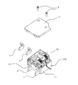
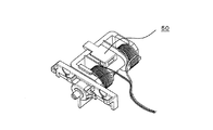
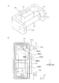
図1はこの発明の実施の形態1における電磁アクチュエータを内蔵した電磁リレーの内部構造を示す分解斜視図、図2は図1に示す電磁アクチュエータの外観斜視図、図3は図2に示す電磁アクチュエータの分解斜視図である。
Hereinafter, an electromagnetic actuator according to
1 is an exploded perspective view showing an internal structure of an electromagnetic relay incorporating an electromagnetic actuator according to
図1において、電磁リレー100は、電磁アクチュエータ50と、第1のケース11とこの第1のケース11に圧入される第2のケース12とカバー13で構成される筐体と、第1の固定接触子1とこの第1の固定接触子1と開閉回路を形成する第1の可動接触子2と、第2の固定接触子3とこの第2の固定接触子3と開閉回路を形成する第2の可動接触子4が電磁リレー100の外部端子として取り付けられて構成されている。なお、カバー13はカバーネジ5により取り付けられる。
In FIG. 1, an
図2および図3を用いて電磁アクチュエータ50の構成について説明する。
第1のヨーク51は磁性材からなり相対向する一対の第1の接極片51aと第2の接極片51bを有してコ字状に形成されている。ボビン52は第1のヨーク51の一対の第1の接極片51aと第2の接極片51b間に配置されており、後述する可動子55が貫挿される可動子挿入孔52aが形成されている。
The configuration of the
The
励磁コイル53はボビン52に巻装され、制御信号ケーブル54による励磁電流通電時には所望の電磁力を発生するものであり、励磁コイル53は第1の制御信号ケーブル54aを通じて制御信号である励磁電流が通電される第1の励磁コイル53aと、第2の制御信号ケーブル54bを通じて制御信号である励磁電流が通電される第2の励磁コイル53bとで構成されている。これら第1の励磁コイル53aと第2の励磁コイル53bによりいわゆる電磁石が形成される。
The
可動子55はボビン52に設けられた可動子挿入孔52a内に貫挿された磁性材からなり、励磁コイル53の磁界により駆動されてZ軸方向に摺動可能に形成され、第1の接極片51aまたは第2の接極片51bに接触して吸着される。また、可動子55の例えば第2の接極片51b側にはネジ穴55aが形成されている。
なお、可動子55は、励磁コイル53の励磁電流の方向に従って移動されるので、第1の励磁コイル53aによる励磁電流の方向の場合はZ軸正方向に移動し、第2の励磁コイル53bによる励磁電流の方向の場合はZ軸負方向に移動する。
The
Since the
永久磁石56は第1のヨーク51とボビン52との間に配置され、第1のヨーク51に磁束を発生させるとともに可動子55を吸引して保持する。第2のヨークである磁性体プレート57は永久磁石56とともに磁気回路を構成する。
第1のヨーク51の第1の接極片51aおよび第2の接極片51bの可動子55が接触される位置には、当接孔51a1、51b1が形成され、例えば第1の接極片51aに形成された当接孔51a1は永久磁石56により吸引される方向と直交する方向に長い孔からなり、図は一例として四角形の多角形状の長孔で構成されている。また、第2の接極片51bに形成された当接孔51b1は、図は一例として丸孔で構成されている。
なお、当接孔51a1は多角形状の長孔に代えて丸孔にしてもよい。要するにこれら当接孔51a1、51b1の形状は、この発明では本質な部分ではないので、これ以上の説明は省略する。
The
Contact holes 51a1 and 51b1 are formed at positions where the
The contact hole 51a1 may be a round hole instead of the polygonal long hole. In short, the shape of the contact holes 51a1 and 51b1 is not an essential part of the present invention, and further description thereof is omitted.
クロスバー58およびロッド59は第1のヨーク51の第2の接極片51b側に配置されており、ロッド59の一方はクロスバー58に係合され、かつEリング固定溝59aが形成されている。ロッド59の他方は第1のヨーク51の第2の接極片51bの当接孔51b1を貫通して可動子55のネジ穴55aに螺合されるロッドネジ部59bが形成されている。
The
接圧バネ60はロッド59とクロスバー58の間に配置され、可動子55が第1のヨーク51の第2の接極片51bに当接すると、第1の固定接触子1と第1の可動接触子2との接触圧力、第2の固定接触子3と第2の可動接触子4との接触圧力を発生させるものである。ロッド59に設けられたEリング固定溝59aに係合されるEリング61が設けられ、クロスバー58がロッド59から外れないようにする。
なお、第1の可動接触子2と第2の可動接触子4はクロスバー58に取り付けられ、可動子55の往復動に応じて可動し、第1の固定接触子1と第2の固定接触子3に接触または非接触し、電磁リレーを構成する。
The
The first
次に、図3に基づいて電磁アクチュエータ50の動作について説明する。第1の励磁コイル53aおよび第2の励磁コイル53bが巻装されたボビン52に設けられた可動子挿入孔52aにZ軸方向に往復動する可動子55が挿入される。可動子55が挿入されたボビン52は略コ字形に形成された第1のヨーク51の接極片51a、51b間に配置され、第1のヨーク51に磁束を発生させる永久磁石56と、永久磁石56と共に磁気回路を構成する磁性体プレート57を介して、ボビン52と第1のヨーク51を係合させる。
Next, the operation of the
励磁コイル53からは可動子55を往復動させるために制御信号が入力可能なように制御信号ケーブル54が引出されている。ここで、可動子55は励磁コイル53から発生する電磁力によりZ軸方向に往復動する構造となっているが、励磁コイル53の励磁が解消された後も永久磁石56の発生する磁力により、第1のヨーク51の第1の接極片51aまたは第2の接極片51bに吸着されて保持されるようになっている。
A
ボビン52に形成された可動子挿入孔52aは可動子55のスムーズな往復動を実現させるためにY軸方向に対してはクリアランスが設けられている。なお、可動子55は常に永久磁石56の発生する磁力によりX軸負方向に吸引されて引き付けられており、また、回転防止構造を備えているためZ軸を中心に回転することはない。
The
可動子55はネジ穴55aが形成されており、クロスバー58と接圧バネ60を固定するロッド59に設けられたロッドネジ部59bを可動子55のネジ穴55aに螺合させることにより、可動子55とロッド59とは一体的に固着される。ロッド59とクロスバー58の間には接圧バネ60が配設されており、可動子55が第1のヨーク51の第2の接極片51bに当接すると、第1の固定接触子1と第1の可動接触子2との接触圧力、第2の固定接触子3と第2の可動接触子4との接触圧力を発生させる。クロスバー58はロッド59に設けられたEリング固定溝59aにEリング61を係合してロッド59から外れないようにしている。
The
次に、この発明の実施の形態1における電磁アクチュエータの主要構成部分について図4〜図6に基づいて説明する。図4は電磁アクチュエータを構成するヨークと永久磁石と可動子を示す斜視図、図5は第1のヨークを省略した側面図とその磁気回路を示す図、図6は電磁アクチュエータの上面図とその磁気回路を示す図である。なお、図4〜図6にお
いては励磁コイル53を巻装するボビン52は省略して示している。
Next, main components of the electromagnetic actuator according to
図4〜図6において、第1のヨーク51は磁性材からなり相対向する一対の第1の接極片51aと第2の接極片51bを有してコ字状に形成されている。励磁コイル53(図6のみ図示)はボビン52(図示省略)に巻装され、励磁電流の通電時には所望の電磁力を発生するものであり、励磁コイル53はON動作方向に駆動するときに励磁電流が通電される第1の励磁コイル53aと、OFF動作方向に駆動するときに励磁電流が通電される第2の励磁コイル53bとで構成されている。これら第1の励磁コイル53aと第2の励磁コイル53bによりいわゆる電磁石が形成される。
4 to 6, the
可動子55はボビン52に設けられた可動子挿入孔52a内に貫挿された磁性材からなり、励磁コイル53の磁界により駆動されてZ軸方向に摺動可能に形成され、第1の接極片51aまたは第2の接極片51bに接触して吸着される。
なお、可動子55は、励磁コイル53の励磁電流の方向に従って移動されるので、第1の励磁コイル53aによる励磁電流の方向の場合はZ軸正方向に移動し、第2の励磁コイル53bによる励磁電流の方向の場合はZ軸負方向に移動する。
The
Since the
永久磁石56は第1のヨーク51と可動子55との間に配置され、第1のヨーク51に磁束を発生させるとともに可動子55を吸引して保持する。第2のヨークである磁性体プレート57は永久磁石56と可動子55間の磁束経路を確保するために、永久磁石56と可動子55との間に配置され、永久磁石56から可動子55へ流入する磁束経路が図5に示すように少なくとも2つに分流した複数経路φ1、φ2となるようコ字状またはU字状に形状された磁極片57aを有している。
The
また、永久磁石56から可動子55へ流入する磁束経路を複数経路にする場合、磁束経路は可動子55の軸に対して対称となるように偶数の経路にする必要がある。このように磁束経路を複数経路にすることにより、永久磁石56と可動子55間に発生する吸引力をキャンセルすることが可能となり、可動子55を永久磁石56側に引張るY方向の側面吸着力Fを低減することができる。
なお、複数の磁束経路を有する第2のヨークである磁性体プレート57は、磁気効率の高い磁性材(例えば、電磁軟鉄SUYなど)の平板をY方向に積層して構成され、可動子55側の1枚を曲げ加工などを行うことにより2つの磁極片57aを有した形状にすることで実現できる。
In addition, when a plurality of magnetic flux paths flowing from the
Note that the
次に、永久磁石56から可動子55へ流入する磁束経路を複数経路にしたことによる、メリットおよびデメリットの発生原因とその対策について説明する。
図7は可動子55を第1の接極片51a側に保持した状態における永久磁石56と可動子55間に発生するY方向の吸着力の変動を示したグラフで、従来構造と本願発明とを対比して示している。図7のそれぞれの左側の棒グラフは投入保持力、右側の棒グラフはY方向の吸着力を示し、従来構造と本願発明は同じ投入保持力に対して、Y方向の吸着力は本願発明の方が従来構造に比較して80%減少している。
このように磁束経路を複数経路に分流することで、状態保持力は同等のままでY方向に発生する吸着力は約80%低減可能であり、これにより駆動性能を向上させることができる。
Next, the cause of the merits and demerits and the countermeasures due to the plurality of magnetic flux paths flowing from the
FIG. 7 is a graph showing fluctuations in the attracting force in the Y direction generated between the
By dividing the magnetic flux path into a plurality of paths in this way, the attracting force generated in the Y direction can be reduced by about 80% while maintaining the same state holding force, thereby improving the driving performance.
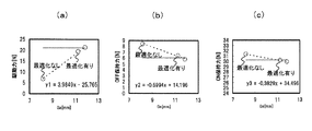
次に、図8は磁束経路を複数経路にした場合、保持状態を引き外す能力が低下することと、その対策としてギャップGaを最適化することにより引き外す能力が増加することを示している。ここで、ギャップGaとは、図6に示す第1のヨーク51の第1の接極片51aおよび第2の接極片51bと磁性体プレート57とのZ方向の隙間のことである。
図8(a)(b)(c)の横軸はギャップGaの距離を示し、図8(a)の縦軸は駆動力、図8(b)(c)の縦軸はOFFおよびON時の保持力を示している。図中の最適化なしの場合は駆動力が小さく、最適化有りの場合は駆動力が大きくなっている。
Next, FIG. 8 shows that when a plurality of magnetic flux paths are used, the ability to trip the holding state is lowered, and the ability to trip is increased by optimizing the gap Ga as a countermeasure. Here, the gap Ga, is that the Z-direction of the gap between the
8A, 8B and 8C, the horizontal axis indicates the distance of the gap Ga, the vertical axis in FIG. 8A is the driving force, and the vertical axis in FIGS. 8B and 8C is OFF and ON. Shows the holding power. In the figure, the driving force is small when there is no optimization, and the driving force is large when there is optimization.
最適化なしの場合に駆動力が小さくなる原因は、磁束経路を複数経路にすることで磁気経路上の磁気抵抗が減少されるためである。一般に磁気抵抗RはR=μ×L/Sで示されるように、磁束断面積に反比例している。
式中、Lは磁性体プレート57と可動子55間の距離、Sは磁性体プレート57と可動子55間の磁束断面積(磁束通過面積)、μは透磁率である。
磁束経路を複数経路にすることで磁束断面積Sは大きくなり、その結果、磁束経路の磁気抵抗Rは減少される。
The reason why the driving force is reduced without optimization is that the magnetic resistance on the magnetic path is reduced by using a plurality of magnetic flux paths. In general, the magnetic resistance R is inversely proportional to the magnetic flux cross-sectional area as indicated by R = μ × L / S.
Wherein, L is the distance between the
By making the magnetic flux path into a plurality of paths, the magnetic flux cross-sectional area S increases, and as a result, the magnetic resistance R of the magnetic flux path is reduced.
磁気抵抗Rが減少されると、図6に示す永久磁石56から磁性体プレート57、可動子55へ流入して第1のヨーク51を通過する磁束Aと磁束Cの磁界強度が増加する。これにより保持状態を引き外すために、第2の励磁コイル53bに通電される励磁電流によって発生する磁束Bによる磁束Aの消磁率が減少する。
かつ、磁束Cの磁界強度が増加することから、第2の励磁コイル53bが発生する磁束Bに対して磁束Cの割合が増加してしまい、ますます引き外し能力が低下する懸念がある。
When the magnetic resistance R is reduced, the
In addition, since the magnetic field strength of the magnetic flux C increases, the ratio of the magnetic flux C to the magnetic flux B generated by the second
この原因について図6に基づいて詳しく説明する。図6に示すように、第2の励磁コイル53bが発生する磁束B(磁気回路に関わらずアンペアターンのみに依存する)は、磁束Aと反対方向の磁気経路を通過する磁束B1と、磁束Cと同方向の磁気経路を通過する磁束B2の2つに分けられ、磁束BはB=B1+B2となる。ここで、磁束B1は可動子55の引き外しに必要な磁束で、磁束B2は引き外しに関係ない磁束ロス分となる。
磁束Cと同じ磁気経路を通過する磁束B2は、磁気抵抗Rの減少により磁界強度が増加することから、可動子55の引き外しに必要な磁束B1は減少し、引き外し能力が低下する。
The cause will be described in detail with reference to FIG. As shown in FIG. 6, the magnetic flux B generated by the second
Since the magnetic field strength of the magnetic flux B2 passing through the same magnetic path as that of the magnetic flux C increases due to a decrease in the magnetic resistance R, the magnetic flux B1 necessary for the trip of the
この課題について図6に示すギャップGaを最適化し、磁気回路を構成することで引き外し能力を確保しつつ、Y方向吸着力を低減できるような構成が可能となる。
即ち、引き外しに関係ない磁束ロス分B2を極力小さくすることで、可動子55の引き外しに必要な磁束B1を確保できる。そのためにはギャップGaの距離を大きく取ることで磁気抵抗Rが増加するため、引き外しに関係ない磁束ロス分B2を削減することができる。但し、ギャップGaの距離を大きく取りすぎると、可動子55の保持力に必要な磁束Aも減少してしまうことから、最適化が必要となってくる。
With respect to this problem, the gap Ga shown in FIG. 6 is optimized, and a magnetic circuit is configured to ensure a tripping capability and to reduce the Y-direction attracting force.
That is, by reducing the magnetic flux loss B2 that is not related to tripping as much as possible, the magnetic flux B1 necessary for tripping the
ギャップGaの最適化について、図8に基づき詳しく説明する。まず、従来構造に対して、実現可能な構成であることを条件として保持力、駆動力共に同等になるような構成を狙う。図8ではギャップGaと駆動力および各状態の保持力の関係について、近似直線で評価している。
最適なx(=Ga)は以下の条件で決定される。
y2(=−0.6994x+14.196)>=OFF保持力
y3(=−0.3829x+34.496)>=ON保持力
を満たすxで、かつy1(=3.9849x−25.765)>=現行駆動力を満たすxを抽出する必要がある。
そして上記3式(y1、y2、y3)と上記の決定条件で最適なギャップGaを決定する。
The optimization of the gap Ga will be described in detail with reference to FIG. First of all, a configuration in which the holding force and the driving force are equal to each other on the condition that the configuration is feasible with respect to the conventional structure is aimed at. In FIG. 8, the relationship between the gap Ga, the driving force, and the holding force in each state is evaluated by an approximate straight line.
The optimum x (= Ga) is determined under the following conditions.
y2 (= −0.6994x + 14.196)> = OFF holding force y3 (= −0.3829x + 34.496)> = x satisfying the ON holding force and y1 (= 3.94949x−25.765)> = current It is necessary to extract x that satisfies the driving force.
Then, an optimum gap Ga is determined by the above three formulas (y1, y2, y3) and the above determination conditions.
なお、磁性体プレート57と可動子55の接極片との当接部との距離(ギャップGa)を、可動子55の移動距離よりも大きくして磁束経路からみたリラクタンス(磁気抵抗)を大きく設定でき、状態開始に必要な駆動磁束の漏れを防ぐことが可能になる。
また、第2のヨークである磁性体プレート57と可動子55のY方向ギャップを広げ、X方向ギャップを狭くすることで、吸着力のさらなる低減が可能となるが、製品の許容寸法や組立誤差などを考慮することで最適化が可能となる。
即ち、磁性体プレート57と可動子55との間の磁気ギャップは、可動子55を永久磁石56側に吸引するY方向の磁気ギャップに対して、複数経路に分流した磁束経路上の磁気ギャップの方を小さくするようにする。
The distance (gap Ga) between the
Also, spread in the Y-direction gap of the
That is, the magnetic gap between the
実施の形態2.
次にこの発明の実施の形態2における電磁アクチュエータを図9、図10により説明する。
図9はこの発明の実施の形態1における電磁アクチュエータを構成するヨークと永久磁石と可動子を示す斜視図、図10は第1のヨークを省略し、図9の黒矢印方向から見た側面図とその磁気回路を示す図である。なお図中、実施の形態1を示す図4および図5と同じまたは相当する部分には同じ符号を付して、説明を省略する。
Next, an electromagnetic actuator according to
FIG. 9 is a perspective view showing a yoke, a permanent magnet, and a mover constituting the electromagnetic actuator according to
実施の形態1では第2のヨークである磁性体プレート57は、磁性材の平板をY方向に積層して構成し、可動子55側の1枚を曲げ加工などを行なうことにより実現していたが、実施の形態2の発明では図9、図10に示すように、第2のヨークである磁性体プレート57は、コ字状またはU字状に形成された磁気効率の高い磁性材(例えば、電磁軟鉄SUYなど)をZ方向に積層して構成したものである。
この構成によっても永久磁石56から可動子55へ流入する磁束経路は図10に示すように少なくとも2つに分流した複数経路φ1、φ2となり、実施の形態1と同じ効果が得られる。
The
Also with this configuration, the magnetic flux path flowing from the
以上のように実施の形態2の構成であれば、第2のヨークである磁性体プレート57の加工も簡易的になり、コスト面で有利になる。
またこの構成であれば、第2のヨークである磁性体プレート57に鎖交する磁束による渦電流損を低減することが可能となり、構造全体の磁気効率が向上する。
なお、実施の形態1および2では、第2のヨークである磁性体プレート57の形状は、コ字状またはU字状に形状された2つの磁極片57aを有して、可動子へ流入する磁束経路が2つの経路となるようにしたが、磁極片57aを4つに形成して4つの経路となるようにしてもよい。
As described above, with the configuration of the second embodiment, the processing of the
Also if this configuration, it is possible to reduce the eddy current loss due to magnetic flux interlinked with the
In first and second embodiments, the shape of the
1:第1の固定接触子、 2:第1の可動接触子、
3:第2の固定接触子、 4:第2の可動接触子、
50:電磁アクチュエータ、 51:第1のヨーク、
51a:第1の接極片、 51b:第2の接極片、
52:ボビン、 53:励磁コイル、
53a:第1の励磁コイル、 53b:第2の励磁コイル、
55:可動子、 56:永久磁石、
57:磁性体プレート(第2のヨーク) 57a:磁性体プレートの磁極片。
1: first fixed contact, 2: first movable contact,
3: Second fixed contact, 4: Second movable contact,
50: Electromagnetic actuator, 51: First yoke,
51a: 1st armature piece, 51b: 2nd armature piece,
52: Bobbin, 53: Excitation coil,
53a: first excitation coil, 53b: second excitation coil,
55: Movable element, 56: Permanent magnet,
57: magnetic plate (second yoke) 57a: magnetic plate pole pieces.
Claims (6)
Priority Applications (1)
| Application Number | Priority Date | Filing Date | Title |
|---|---|---|---|
| JP2011129108A JP5697552B2 (en) | 2011-06-09 | 2011-06-09 | Electromagnetic actuator and electromagnetic relay using the same |
Applications Claiming Priority (1)
| Application Number | Priority Date | Filing Date | Title |
|---|---|---|---|
| JP2011129108A JP5697552B2 (en) | 2011-06-09 | 2011-06-09 | Electromagnetic actuator and electromagnetic relay using the same |
Publications (3)
| Publication Number | Publication Date |
|---|---|
| JP2012257396A JP2012257396A (en) | 2012-12-27 |
| JP2012257396A5 JP2012257396A5 (en) | 2013-11-28 |
| JP5697552B2 true JP5697552B2 (en) | 2015-04-08 |
Family
ID=47528399
Family Applications (1)
| Application Number | Title | Priority Date | Filing Date |
|---|---|---|---|
| JP2011129108A Active JP5697552B2 (en) | 2011-06-09 | 2011-06-09 | Electromagnetic actuator and electromagnetic relay using the same |
Country Status (1)
| Country | Link |
|---|---|
| JP (1) | JP5697552B2 (en) |
Families Citing this family (2)
| Publication number | Priority date | Publication date | Assignee | Title |
|---|---|---|---|---|
| JP6422457B2 (en) * | 2016-03-04 | 2018-11-14 | 三菱電機株式会社 | Electromagnetic actuator and electromagnetic relay using the same |
| WO2021176669A1 (en) * | 2020-03-05 | 2021-09-10 | 三菱電機株式会社 | Electromagnetic relay |
Family Cites Families (2)
| Publication number | Priority date | Publication date | Assignee | Title |
|---|---|---|---|---|
| JP2004146336A (en) * | 2002-08-27 | 2004-05-20 | Mitsubishi Electric Corp | Operating device and switch using operating device |
| JP5280792B2 (en) * | 2008-10-08 | 2013-09-04 | 三菱電機株式会社 | Electromagnetic actuator |
-
2011
- 2011-06-09 JP JP2011129108A patent/JP5697552B2/en active Active
Also Published As
| Publication number | Publication date |
|---|---|
| JP2012257396A (en) | 2012-12-27 |
Similar Documents
| Publication | Publication Date | Title |
|---|---|---|
| EP3183406A1 (en) | Magnetically latching flux-shifting electromechanical actuator | |
| JP2007037273A (en) | Vibratory linear actuator | |
| JP4880313B2 (en) | Cylinder type linear actuator | |
| CN108352240B (en) | Linear actuator with improved magnetic stability and disengagement force | |
| JPH0461305A (en) | Bistable solenoid and knitting machine using the same | |
| JP2009240046A (en) | Electromagnetic actuator | |
| JP5697552B2 (en) | Electromagnetic actuator and electromagnetic relay using the same | |
| JPWO2019021531A1 (en) | Electromagnetic actuator and hydraulic adjustment mechanism | |
| JP5280792B2 (en) | Electromagnetic actuator | |
| JP4754975B2 (en) | Polarized electromagnet | |
| JP2012257396A5 (en) | ||
| JPH0992526A (en) | Electromagnetic device | |
| JP4515976B2 (en) | Operating device and switchgear provided with the operating device | |
| JP5743863B2 (en) | Electromagnetic actuator and electromagnetic relay using the same | |
| JP4722601B2 (en) | Electromagnetic operation mechanism, power switch using the same, and power switch | |
| JP2002112519A (en) | Electromagnetially reciprocating driver | |
| JP2018120840A (en) | Electromagnetic relay | |
| KR100302908B1 (en) | A permant magnet excited linear actuator | |
| JP2017157493A (en) | Electromagnetic actuator and electromagnetic relay using the same | |
| JP4742790B2 (en) | Electromagnet device and electromagnetic relay | |
| JP3367180B2 (en) | Electromagnetic actuator | |
| JP5644276B2 (en) | Linear actuator | |
| JP2006014464A (en) | Linear actuator | |
| JP2011004451A (en) | Linear actuator | |
| JP3731011B2 (en) | Single pole linear DC motor |
Legal Events
| Date | Code | Title | Description |
|---|---|---|---|
| A521 | Request for written amendment filed |
Free format text: JAPANESE INTERMEDIATE CODE: A523 Effective date: 20131008 |
|
| A621 | Written request for application examination |
Free format text: JAPANESE INTERMEDIATE CODE: A621 Effective date: 20131008 |
|
| A131 | Notification of reasons for refusal |
Free format text: JAPANESE INTERMEDIATE CODE: A131 Effective date: 20140723 |
|
| A977 | Report on retrieval |
Free format text: JAPANESE INTERMEDIATE CODE: A971007 Effective date: 20140723 |
|
| A521 | Request for written amendment filed |
Free format text: JAPANESE INTERMEDIATE CODE: A523 Effective date: 20140903 |
|
| TRDD | Decision of grant or rejection written | ||
| A01 | Written decision to grant a patent or to grant a registration (utility model) |
Free format text: JAPANESE INTERMEDIATE CODE: A01 Effective date: 20150113 |
|
| A61 | First payment of annual fees (during grant procedure) |
Free format text: JAPANESE INTERMEDIATE CODE: A61 Effective date: 20150210 |
|
| R151 | Written notification of patent or utility model registration |
Ref document number: 5697552 Country of ref document: JP Free format text: JAPANESE INTERMEDIATE CODE: R151 |
|
| R250 | Receipt of annual fees |
Free format text: JAPANESE INTERMEDIATE CODE: R250 |
|
| R250 | Receipt of annual fees |
Free format text: JAPANESE INTERMEDIATE CODE: R250 |
|
| R250 | Receipt of annual fees |
Free format text: JAPANESE INTERMEDIATE CODE: R250 |
|
| R250 | Receipt of annual fees |
Free format text: JAPANESE INTERMEDIATE CODE: R250 |
|
| R250 | Receipt of annual fees |
Free format text: JAPANESE INTERMEDIATE CODE: R250 |
|
| R250 | Receipt of annual fees |
Free format text: JAPANESE INTERMEDIATE CODE: R250 |
|
| R250 | Receipt of annual fees |
Free format text: JAPANESE INTERMEDIATE CODE: R250 |