JP5695564B2 - Tissue access site system and method - Google Patents
Tissue access site system and method Download PDFInfo
- Publication number
- JP5695564B2 JP5695564B2 JP2011517309A JP2011517309A JP5695564B2 JP 5695564 B2 JP5695564 B2 JP 5695564B2 JP 2011517309 A JP2011517309 A JP 2011517309A JP 2011517309 A JP2011517309 A JP 2011517309A JP 5695564 B2 JP5695564 B2 JP 5695564B2
- Authority
- JP
- Japan
- Prior art keywords
- tissue
- access site
- closure
- site system
- incision
- Prior art date
- Legal status (The legal status is an assumption and is not a legal conclusion. Google has not performed a legal analysis and makes no representation as to the accuracy of the status listed.)
- Expired - Fee Related
Links
- 238000000034 method Methods 0.000 title description 33
- 238000002224 dissection Methods 0.000 claims description 20
- 230000037361 pathway Effects 0.000 claims 1
- 210000001519 tissue Anatomy 0.000 description 226
- 210000001367 artery Anatomy 0.000 description 39
- 210000004204 blood vessel Anatomy 0.000 description 18
- 230000003447 ipsilateral effect Effects 0.000 description 14
- 238000004873 anchoring Methods 0.000 description 11
- 229920001296 polysiloxane Polymers 0.000 description 11
- 230000002792 vascular Effects 0.000 description 10
- 238000011282 treatment Methods 0.000 description 6
- 239000000853 adhesive Substances 0.000 description 5
- 230000001070 adhesive effect Effects 0.000 description 5
- 230000006835 compression Effects 0.000 description 5
- 238000007906 compression Methods 0.000 description 5
- 239000000463 material Substances 0.000 description 5
- 230000007246 mechanism Effects 0.000 description 5
- 230000008901 benefit Effects 0.000 description 4
- 230000006378 damage Effects 0.000 description 4
- 229920000642 polymer Polymers 0.000 description 4
- 230000009467 reduction Effects 0.000 description 4
- 208000002223 abdominal aortic aneurysm Diseases 0.000 description 3
- 208000007474 aortic aneurysm Diseases 0.000 description 3
- 238000013459 approach Methods 0.000 description 3
- 239000008280 blood Substances 0.000 description 3
- 210000004369 blood Anatomy 0.000 description 3
- 230000017531 blood circulation Effects 0.000 description 3
- 229910052751 metal Inorganic materials 0.000 description 3
- 239000002184 metal Substances 0.000 description 3
- HLXZNVUGXRDIFK-UHFFFAOYSA-N nickel titanium Chemical compound [Ti].[Ti].[Ti].[Ti].[Ti].[Ti].[Ti].[Ti].[Ti].[Ti].[Ti].[Ni].[Ni].[Ni].[Ni].[Ni].[Ni].[Ni].[Ni].[Ni].[Ni].[Ni].[Ni].[Ni].[Ni] HLXZNVUGXRDIFK-UHFFFAOYSA-N 0.000 description 3
- 229910001000 nickel titanium Inorganic materials 0.000 description 3
- 238000002360 preparation method Methods 0.000 description 3
- 229920000954 Polyglycolide Polymers 0.000 description 2
- 210000000709 aorta Anatomy 0.000 description 2
- 238000012790 confirmation Methods 0.000 description 2
- 230000010339 dilation Effects 0.000 description 2
- 210000001105 femoral artery Anatomy 0.000 description 2
- 238000003780 insertion Methods 0.000 description 2
- 230000037431 insertion Effects 0.000 description 2
- 238000012986 modification Methods 0.000 description 2
- 230000004048 modification Effects 0.000 description 2
- 230000008520 organization Effects 0.000 description 2
- RVTZCBVAJQQJTK-UHFFFAOYSA-N oxygen(2-);zirconium(4+) Chemical compound [O-2].[O-2].[Zr+4] RVTZCBVAJQQJTK-UHFFFAOYSA-N 0.000 description 2
- 229920000747 poly(lactic acid) Polymers 0.000 description 2
- 239000004626 polylactic acid Substances 0.000 description 2
- 239000000565 sealant Substances 0.000 description 2
- 230000006641 stabilisation Effects 0.000 description 2
- 238000011105 stabilization Methods 0.000 description 2
- 229910001220 stainless steel Inorganic materials 0.000 description 2
- 239000010935 stainless steel Substances 0.000 description 2
- 206010034203 Pectus Carinatum Diseases 0.000 description 1
- 239000004743 Polypropylene Substances 0.000 description 1
- 230000003187 abdominal effect Effects 0.000 description 1
- 238000002679 ablation Methods 0.000 description 1
- 229910052782 aluminium Inorganic materials 0.000 description 1
- XAGFODPZIPBFFR-UHFFFAOYSA-N aluminium Chemical compound [Al] XAGFODPZIPBFFR-UHFFFAOYSA-N 0.000 description 1
- 239000011324 bead Substances 0.000 description 1
- 230000015572 biosynthetic process Effects 0.000 description 1
- 230000000740 bleeding effect Effects 0.000 description 1
- 239000000919 ceramic Substances 0.000 description 1
- 239000000701 coagulant Substances 0.000 description 1
- 238000010276 construction Methods 0.000 description 1
- 238000011161 development Methods 0.000 description 1
- 230000023597 hemostasis Effects 0.000 description 1
- 230000002439 hemostatic effect Effects 0.000 description 1
- 210000001621 ilium bone Anatomy 0.000 description 1
- 238000012544 monitoring process Methods 0.000 description 1
- 210000000056 organ Anatomy 0.000 description 1
- 230000000149 penetrating effect Effects 0.000 description 1
- 230000035515 penetration Effects 0.000 description 1
- 230000002093 peripheral effect Effects 0.000 description 1
- 229920001606 poly(lactic acid-co-glycolic acid) Polymers 0.000 description 1
- 239000004633 polyglycolic acid Substances 0.000 description 1
- -1 polypropylene Polymers 0.000 description 1
- 229920001155 polypropylene Polymers 0.000 description 1
- 230000002028 premature Effects 0.000 description 1
- 230000008569 process Effects 0.000 description 1
- 230000000717 retained effect Effects 0.000 description 1
- 238000012552 review Methods 0.000 description 1
- 239000007787 solid Substances 0.000 description 1
- 238000012360 testing method Methods 0.000 description 1
- 230000001225 therapeutic effect Effects 0.000 description 1
- 239000003106 tissue adhesive Substances 0.000 description 1
- 230000000451 tissue damage Effects 0.000 description 1
- 231100000827 tissue damage Toxicity 0.000 description 1
- 230000001960 triggered effect Effects 0.000 description 1
- XLYOFNOQVPJJNP-UHFFFAOYSA-N water Substances O XLYOFNOQVPJJNP-UHFFFAOYSA-N 0.000 description 1
Images


Classifications
-
- A—HUMAN NECESSITIES
- A61—MEDICAL OR VETERINARY SCIENCE; HYGIENE
- A61B—DIAGNOSIS; SURGERY; IDENTIFICATION
- A61B17/00—Surgical instruments, devices or methods, e.g. tourniquets
- A61B17/32—Surgical cutting instruments
- A61B17/3209—Incision instruments
-
- A—HUMAN NECESSITIES
- A61—MEDICAL OR VETERINARY SCIENCE; HYGIENE
- A61B—DIAGNOSIS; SURGERY; IDENTIFICATION
- A61B17/00—Surgical instruments, devices or methods, e.g. tourniquets
- A61B17/0057—Implements for plugging an opening in the wall of a hollow or tubular organ, e.g. for sealing a vessel puncture or closing a cardiac septal defect
-
- A—HUMAN NECESSITIES
- A61—MEDICAL OR VETERINARY SCIENCE; HYGIENE
- A61B—DIAGNOSIS; SURGERY; IDENTIFICATION
- A61B17/00—Surgical instruments, devices or methods, e.g. tourniquets
- A61B17/04—Surgical instruments, devices or methods, e.g. tourniquets for suturing wounds; Holders or packages for needles or suture materials
- A61B17/0469—Suturing instruments for use in minimally invasive surgery, e.g. endoscopic surgery
-
- A—HUMAN NECESSITIES
- A61—MEDICAL OR VETERINARY SCIENCE; HYGIENE
- A61B—DIAGNOSIS; SURGERY; IDENTIFICATION
- A61B17/00—Surgical instruments, devices or methods, e.g. tourniquets
- A61B17/04—Surgical instruments, devices or methods, e.g. tourniquets for suturing wounds; Holders or packages for needles or suture materials
- A61B17/0482—Needle or suture guides
-
- A—HUMAN NECESSITIES
- A61—MEDICAL OR VETERINARY SCIENCE; HYGIENE
- A61B—DIAGNOSIS; SURGERY; IDENTIFICATION
- A61B17/00—Surgical instruments, devices or methods, e.g. tourniquets
- A61B17/08—Wound clamps or clips, i.e. not or only partly penetrating the tissue ; Devices for bringing together the edges of a wound
-
- A—HUMAN NECESSITIES
- A61—MEDICAL OR VETERINARY SCIENCE; HYGIENE
- A61B—DIAGNOSIS; SURGERY; IDENTIFICATION
- A61B17/00—Surgical instruments, devices or methods, e.g. tourniquets
- A61B17/34—Trocars; Puncturing needles
- A61B17/3415—Trocars; Puncturing needles for introducing tubes or catheters, e.g. gastrostomy tubes, drain catheters
-
- A—HUMAN NECESSITIES
- A61—MEDICAL OR VETERINARY SCIENCE; HYGIENE
- A61B—DIAGNOSIS; SURGERY; IDENTIFICATION
- A61B17/00—Surgical instruments, devices or methods, e.g. tourniquets
- A61B17/34—Trocars; Puncturing needles
- A61B17/3417—Details of tips or shafts, e.g. grooves, expandable, bendable; Multiple coaxial sliding cannulas, e.g. for dilating
-
- A—HUMAN NECESSITIES
- A61—MEDICAL OR VETERINARY SCIENCE; HYGIENE
- A61B—DIAGNOSIS; SURGERY; IDENTIFICATION
- A61B17/00—Surgical instruments, devices or methods, e.g. tourniquets
- A61B17/32—Surgical cutting instruments
- A61B17/3205—Excision instruments
- A61B17/32053—Punch like cutting instruments, e.g. using a cylindrical or oval knife
-
- A—HUMAN NECESSITIES
- A61—MEDICAL OR VETERINARY SCIENCE; HYGIENE
- A61B—DIAGNOSIS; SURGERY; IDENTIFICATION
- A61B17/00—Surgical instruments, devices or methods, e.g. tourniquets
- A61B17/0057—Implements for plugging an opening in the wall of a hollow or tubular organ, e.g. for sealing a vessel puncture or closing a cardiac septal defect
- A61B2017/00637—Implements for plugging an opening in the wall of a hollow or tubular organ, e.g. for sealing a vessel puncture or closing a cardiac septal defect for sealing trocar wounds through abdominal wall
-
- A—HUMAN NECESSITIES
- A61—MEDICAL OR VETERINARY SCIENCE; HYGIENE
- A61B—DIAGNOSIS; SURGERY; IDENTIFICATION
- A61B17/00—Surgical instruments, devices or methods, e.g. tourniquets
- A61B17/0057—Implements for plugging an opening in the wall of a hollow or tubular organ, e.g. for sealing a vessel puncture or closing a cardiac septal defect
- A61B2017/00646—Type of implements
- A61B2017/00663—Type of implements the implement being a suture
-
- A—HUMAN NECESSITIES
- A61—MEDICAL OR VETERINARY SCIENCE; HYGIENE
- A61B—DIAGNOSIS; SURGERY; IDENTIFICATION
- A61B17/00—Surgical instruments, devices or methods, e.g. tourniquets
- A61B17/0057—Implements for plugging an opening in the wall of a hollow or tubular organ, e.g. for sealing a vessel puncture or closing a cardiac septal defect
- A61B2017/00672—Locating means therefor, e.g. bleed back lumen
-
- A—HUMAN NECESSITIES
- A61—MEDICAL OR VETERINARY SCIENCE; HYGIENE
- A61B—DIAGNOSIS; SURGERY; IDENTIFICATION
- A61B17/00—Surgical instruments, devices or methods, e.g. tourniquets
- A61B2017/00743—Type of operation; Specification of treatment sites
- A61B2017/00778—Operations on blood vessels
-
- A—HUMAN NECESSITIES
- A61—MEDICAL OR VETERINARY SCIENCE; HYGIENE
- A61B—DIAGNOSIS; SURGERY; IDENTIFICATION
- A61B17/00—Surgical instruments, devices or methods, e.g. tourniquets
- A61B17/04—Surgical instruments, devices or methods, e.g. tourniquets for suturing wounds; Holders or packages for needles or suture materials
- A61B17/0469—Suturing instruments for use in minimally invasive surgery, e.g. endoscopic surgery
- A61B2017/0472—Multiple-needled, e.g. double-needled, instruments
-
- A—HUMAN NECESSITIES
- A61—MEDICAL OR VETERINARY SCIENCE; HYGIENE
- A61B—DIAGNOSIS; SURGERY; IDENTIFICATION
- A61B17/00—Surgical instruments, devices or methods, e.g. tourniquets
- A61B17/22—Implements for squeezing-off ulcers or the like on the inside of inner organs of the body; Implements for scraping-out cavities of body organs, e.g. bones; Calculus removers; Calculus smashing apparatus; Apparatus for removing obstructions in blood vessels, not otherwise provided for
- A61B2017/22038—Implements for squeezing-off ulcers or the like on the inside of inner organs of the body; Implements for scraping-out cavities of body organs, e.g. bones; Calculus removers; Calculus smashing apparatus; Apparatus for removing obstructions in blood vessels, not otherwise provided for with a guide wire
-
- A—HUMAN NECESSITIES
- A61—MEDICAL OR VETERINARY SCIENCE; HYGIENE
- A61B—DIAGNOSIS; SURGERY; IDENTIFICATION
- A61B17/00—Surgical instruments, devices or methods, e.g. tourniquets
- A61B17/34—Trocars; Puncturing needles
- A61B17/3417—Details of tips or shafts, e.g. grooves, expandable, bendable; Multiple coaxial sliding cannulas, e.g. for dilating
- A61B2017/3454—Details of tips
-
- A—HUMAN NECESSITIES
- A61—MEDICAL OR VETERINARY SCIENCE; HYGIENE
- A61M—DEVICES FOR INTRODUCING MEDIA INTO, OR ONTO, THE BODY; DEVICES FOR TRANSDUCING BODY MEDIA OR FOR TAKING MEDIA FROM THE BODY; DEVICES FOR PRODUCING OR ENDING SLEEP OR STUPOR
- A61M29/00—Dilators with or without means for introducing media, e.g. remedies
Landscapes
- Health & Medical Sciences (AREA)
- Life Sciences & Earth Sciences (AREA)
- Surgery (AREA)
- Molecular Biology (AREA)
- General Health & Medical Sciences (AREA)
- Biomedical Technology (AREA)
- Heart & Thoracic Surgery (AREA)
- Medical Informatics (AREA)
- Nuclear Medicine, Radiotherapy & Molecular Imaging (AREA)
- Animal Behavior & Ethology (AREA)
- Engineering & Computer Science (AREA)
- Public Health (AREA)
- Veterinary Medicine (AREA)
- Pathology (AREA)
- Gastroenterology & Hepatology (AREA)
- Cardiology (AREA)
- Surgical Instruments (AREA)
Description
本発明は、組織アクセス部位を開口/拡張および閉鎖するためのシステムおよび方法に関し、さらに詳しくは、大腿腿血管アクセスで利用されるような大血管アクセス部位を開口/拡張および閉鎖するために使用することのできるシステムに関する。 The present invention relates to a system and method for opening / expanding and closing a tissue access site, and more particularly for use in opening / expanding and closing a large vessel access site, such as utilized in femoral vascular access. It relates to a system that can.
米国では、年間500万件を超える診断または治療目的の大腿動脈カテーテル法を伴う経皮的インターベンションが実施されている。 In the United States, more than 5 million percutaneous interventions with femoral artery catheterization are performed annually for diagnostic or therapeutic purposes.
ほとんどの処置は小さいシースアクセス部位(5〜8F)を介して実施され、したがってそのようなアクセス部位の閉鎖は、典型的には3ないし6時間の延長ベッド安静と組み合わせて、15〜30分間の手動または機械的圧縮を用いて達成することができる。 Most procedures are performed through a small sheath access site (5-8F), so closure of such an access site is typically 15-30 minutes in combination with an extended bed rest of 3-6 hours. It can be achieved using manual or mechanical compression.
しかし、手動圧縮は患者の不快感を生じるおそれがあり、かつ時間および資源集約的であり、そういうものとして、より迅速で患者親和性の高い閉鎖の必要性が1990年代初期の閉鎖装置の導入を導いた。それ以来、血管閉鎖システムは、様々な血管処置に対しより広い患者アクセスをもたらすように簡素化されてきた。今では多くの供給源から入手可能であり、これらの装置は処置時間を短縮し、患者を早期に歩行できるようにし、出血を最小化し、かつおそらく入院治療に関連するコストを低減する。 However, manual compression can cause patient discomfort and is time and resource intensive, as such, the need for faster and more patient-friendly closure has led to the introduction of closure devices in the early 1990s. lead. Since then, vascular closure systems have been simplified to provide wider patient access for various vascular procedures. Now available from many sources, these devices reduce treatment time, allow patients to walk early, minimize bleeding, and possibly reduce costs associated with hospitalization.
現在、市場および様々な開発段階にある多数の装置が存在し、そのような装置は縫合糸、パッチ、接着剤、凝固薬、および/もしくはステープル、またはエネルギ源を使用して、処置後のアクセス部位を効果的に封止する There are currently a large number of devices on the market and in various stages of development, such devices using sutures, patches, adhesives, coagulants, and / or staples, or energy sources, and post-procedure access. Effectively seal the site
これらの装置は小さいアクセス部位(<10F)の閉鎖用に特別に設計されたが、90年代末期以来、大口径のアクセス部位(>18F)で縫合閉鎖装置(特に縫合および止血装置)を利用する試みがなされており、大きいアクセス部位の「自動」閉鎖に対する少なくとも限定的な必要性を示している。大口径アクセス部位の閉鎖は典型的には、露出した動脈の手動縫合を介して行われ、したがってスペシャリストの存在が要求される一方、多大な時間を要するのみならず、侵襲性が高い。 These devices were specially designed for the closure of small access sites (<10F), but have utilized suture closure devices (especially suture and hemostasis devices) at large caliber access sites (> 18F) since the late 90s Attempts have been made and show at least a limited need for “automatic” closure of large access sites. Closure of the large diameter access site is typically done through manual sutures of exposed arteries, thus requiring the presence of a specialist while requiring a significant amount of time as well as being highly invasive.
今日まで実施された研究は、大きさが18F未満のアクセス部位のそのような装置による閉鎖は効果的であり、大成功であるが、それより大きい口径のアクセス部位(例えば22F)はあまり効果的ではないことを示している。 Studies conducted to date have shown that closure of access sites less than 18F in size with such devices is effective and very successful, but access sites with larger apertures (eg 22F) are less effective It is not.
現在、大口径アクセス部位に実施される処置の件数は少ないが、現在の傾向からそのような処置の件数は将来増大することが予想され、それに伴ってシースサイズの低減も起きるが、そのような低減があってもシースの平均サイズは依然として18Fを超えるであろう。 Currently, the number of treatments performed on large-caliber access sites is small, but current trends are expected to increase the number of such treatments in the future, with concomitant reductions in sheath size. Even with the reduction, the average size of the sheath will still exceed 18F.
本発明を実行に移しながら、本発明の発明者らは、医師にアクセス部位の生成および閉鎖に対する制御を提供するアクセス部位システムを考案した。 While putting the present invention into practice, the inventors of the present invention have devised an access site system that provides physicians with control over access site creation and closure.
本発明の1態様では、(a)予め定められた形状の組織縁部によって包囲された組織アクセス部位を組織に生成するように設計された要素と、(b)組織縁部の少なくとも1つに対応する領域の組織に少なくとも1つの閉鎖要素を取り付けるための組織閉鎖装置とを備えた、組織アクセス部位システムを提供する。 In one aspect of the invention, (a) an element designed to create a tissue access site surrounded by a tissue edge of a predetermined shape in the tissue; and (b) at least one of the tissue edges. A tissue access site system is provided that includes a tissue closure device for attaching at least one closure element to tissue in a corresponding area.
本発明の別の態様では、(a)組織を切開して予め定められた形状の組織縁部によって包囲される組織アクセス部位を生成するステップと、(b)組織縁部の少なくとも1つに対応する領域の組織に少なくとも1つの閉鎖要素を取り付けるステップと、(c)組織アクセス部位を使用して組織を通してアクセスを得るステップとを含む、組織を通してアクセスを達成する方法を提供する。 In another aspect of the invention, (a) incising the tissue to create a tissue access site surrounded by a tissue edge of a predetermined shape; and (b) corresponding to at least one of the tissue edges. A method of achieving access through tissue comprising the steps of attaching at least one closure element to tissue in a region to be accessed and (c) obtaining access through tissue using a tissue access site.
本発明の好適な実施形態のさらなる特徴によると、ステップ(b)はステップ(a)より前に行われる。 According to further features in preferred embodiments of the present invention, step (b) is performed before step (a).
記載した好適な実施形態のさらに別の特徴によると、組織切開要素は、組織を十字パターンに切開するように設計される。 According to still further features in the described preferred embodiments the tissue cutting element is designed to cut tissue in a cross pattern.
記載した好適な実施形態のさらに別の特徴によると、組織切開要素は、三角形の形状を有する組織縁部を生成するように設計される。 According to still further features in the described preferred embodiments the tissue dissection element is designed to produce a tissue edge having a triangular shape.
記載した好適な実施形態のさらに別の特徴によると、組織切開要素は、組織アクセス部位を切開して組織内に進入するように設計される。 According to still further features in the described preferred embodiments the tissue dissection element is designed to incise through the tissue access site and enter the tissue.
記載した好適な実施形態のさらに別の特徴によると、組織切開要素は、組織アクセス部位を通して組織内に進入し、かつ組織アクセス部位を切開して組織から外に出るように設計される。 According to still further features in the described preferred embodiments the tissue dissection element is designed to enter the tissue through the tissue access site and to dissect the tissue access site and out of the tissue.
記載した好適な実施形態のさらに別の特徴によると、少なくとも1つの閉鎖要素は縫合糸であり、さらに組織閉鎖装置は少なくとも1つの組織穿刺要素を含む。 According to still further features in the described preferred embodiments the at least one closure element is a suture and the tissue closure device further includes at least one tissue piercing element.
記載した好適な実施形態のさらに別の特徴によると、システムは、組織アクセス部位の生成の前、途中、または後で少なくとも1つの閉鎖要素が組織縁部の少なくとも1つに対応する領域の組織に取り付けられるように、組織切開要素および組織閉鎖装置の動作を協調させるように構成される。 According to still further features in the described preferred embodiments the system applies to tissue in a region where at least one closure element corresponds to at least one of the tissue edges before, during or after generation of the tissue access site. Attached is configured to coordinate the operation of the tissue dissection element and the tissue closure device.
記載した好適な実施形態のさらに別の特徴によると、組織閉鎖装置は、組織に縫合糸を出し入れすることのできる縫合装置である。 According to still further features in the described preferred embodiments the tissue closure device is a suturing device capable of inserting and removing sutures from tissue.
記載した好適な実施形態のさらに別の特徴によると、少なくとも1つの閉鎖要素はクリップである。 According to still further features in the described preferred embodiments the at least one closure element is a clip.
記載した好適な実施形態のさらに別の特徴によると、組織切開要素および組織閉鎖装置は単一筐体内に組み込まれる。 According to still further features in the described preferred embodiments the tissue dissection element and the tissue closure device are incorporated into a single housing.
記載した好適な実施形態のさらに別の特徴によると、システムはさらに、組織にパッチを送達するためのパッチ送達装置を含む。 According to still further features in the described preferred embodiments the system further includes a patch delivery device for delivering the patch to the tissue.
記載した好適な実施形態のさらに別の特徴によると、システムはさらに、接着剤またはシーラント送達装置を含む。 According to still further features in the described preferred embodiments the system further comprises an adhesive or sealant delivery device.
本発明のさらに別の態様では、(a)組織を切開して予め定められた形状の組織縁部によって包囲される組織アクセス部位を生成するステップと、(b)組織縁部の少なくとも1つに対応する領域の組織に少なくとも1つの閉鎖要素を取り付けるステップと、(c)組織アクセス部位を介して処置を実施するステップと、(d)少なくとも1つの閉鎖要素を使用して組織アクセス部位を閉鎖するステップとを含む、組織を介するアクセスを必要とする処置を実行する方法を提供する。 In yet another aspect of the invention, (a) incising the tissue to generate a tissue access site surrounded by a tissue edge of a predetermined shape; and (b) at least one of the tissue edges. Attaching at least one closure element to tissue in a corresponding region; (c) performing a procedure via the tissue access site; and (d) closing the tissue access site using the at least one closure element. And a method for performing a procedure requiring access through an organization.
記載した好適な実施形態のさらに別の特徴によると、ステップ(b)はステップ(a)より前に行われる。 According to still further features in the described preferred embodiments step (b) is performed before step (a).
本発明のさらに別の態様では、(a)組織の穴を拡張するように設計された組織拡張要素と、(b)穴の周りの組織に少なくとも1つの閉鎖要素を取り付けるための組織閉鎖装置とを備えた、組織アクセス部位システムを提供する。 In yet another aspect of the invention, (a) a tissue expansion element designed to expand a hole in tissue, and (b) a tissue closure device for attaching at least one closure element to the tissue around the hole. A tissue access site system is provided.
記載した好適な実施形態のさらに別の特徴によると、組織拡張要素は、ガイドワイヤで配置されるように設計される。 According to still further features in the described preferred embodiments the tissue expansion element is designed to be placed with a guide wire.
記載した好適な実施形態のさらに別の特徴によると、組織拡張要素は、穴の周りの組織の損傷を最小化するように、穴を制御可能に拡張するように設計される。 According to still further features in the described preferred embodiments the tissue expansion element is designed to controllably expand the hole so as to minimize tissue damage around the hole.
記載した好適な実施形態のさらに別の特徴によると、少なくとも1つの閉鎖要素は縫合糸であり、さらに組織閉鎖装置は少なくとも1つの組織穿刺要素を含む。 According to still further features in the described preferred embodiments the at least one closure element is a suture and the tissue closure device further includes at least one tissue piercing element.
記載した好適な実施形態のさらに別の特徴によると、システムは、穴の拡張の前、途中、または後で少なくとも1つの閉鎖要素が穴の周りの組織に取り付けられるように、組織拡張要素および組織閉鎖装置の動作を協調させるように構成される。 According to still further features in the described preferred embodiments the system includes a tissue expansion element and tissue so that at least one closure element is attached to the tissue around the hole before, during or after expansion of the hole. It is configured to coordinate the operation of the closure device.
記載した好適な実施形態のさらに別の特徴によると、組織閉鎖装置は、縫合糸を組織に出し入れすることのできる縫合装置である。 According to still further features in the described preferred embodiments the tissue closure device is a suturing device capable of moving sutures into and out of tissue.
記載した好適な実施形態のさらに別の特徴によると、少なくとも1つの閉鎖要素はクリップである。 According to still further features in the described preferred embodiments the at least one closure element is a clip.
記載した好適な実施形態のさらに別の特徴によると、組織拡張要素および組織閉鎖装置は単一筐体内に組み込まれる。 According to still further features in the described preferred embodiments the tissue expansion element and the tissue closure device are incorporated into a single housing.
本発明のさらに別の態様では、組織の1つ以上の皮弁を有するアクセス部位を形成することのできる切開パターンを有する刃を備えた、組織にアクセス部位を生成するための装置を提供する。 In yet another aspect of the present invention, an apparatus for generating an access site in tissue is provided that includes a blade having an incision pattern capable of forming an access site having one or more flaps of tissue.
本発明のさらに別の態様では、対側入口部位から同側血管にアクセスするように構成されたバルーンカテーテルを提供する。 In yet another aspect of the invention, a balloon catheter configured to access an ipsilateral vessel from a contralateral entrance site is provided.
記載した好適な実施形態のさらに別の特徴によると、バルーンカテーテルは伸展性バルーンを含む。 According to still further features in the described preferred embodiments the balloon catheter comprises an extensible balloon.
本発明は、アクセス部位の生成および閉鎖を制御するために使用することのできるシステムを提供することによって、現在公知の構成の欠点に対処することに成功している。 The present invention succeeds in addressing the shortcomings of currently known configurations by providing a system that can be used to control access site creation and closure.
別途定義されない限り、本明細書で使用されるすべての技術的用語および/または科学的用語は、本発明が属する技術分野の当業者によって一般に理解されるのと同じ意味を有する。本明細書に記載される方法および材料と類似または同等である方法および材料を本発明の実施または試験において使用することができるが、好適な方法および/または材料が以下に記載される。矛盾する場合には、定義を含めて、本特許明細書が優先する。加えて、材料、方法および実施例は例示にすぎず、限定であることは意図されない。 Unless defined otherwise, all technical and / or scientific terms used herein have the same meaning as commonly understood by one of ordinary skill in the art to which this invention belongs. Although methods and materials similar or equivalent to those described herein can be used in the practice or testing of the present invention, suitable methods and / or materials are described below. In case of conflict, the patent specification, including definitions, will control. In addition, the materials, methods, and examples are illustrative only and not intended to be limiting.
本明細書では本発明のいくつかの実施形態を単に例示し図面を参照して説明する。特に詳細に図面を参照して、示されている詳細が例示として本発明の好ましい実施態様を例示考察することだけを目的としており、本発明の原理や概念の側面の最も有用でかつ容易に理解される説明であると考えられるものを提供するために提示していることを強調するものである。この点について、本発明を基本的に理解するのに必要である以上に詳細に本発明の構造の詳細は示さないが、図面について行う説明によって本発明のいくつもの形態を実施する方法は当業者には明らかになるであろう。 Several embodiments of the invention are merely illustrated herein and described with reference to the drawings. The details shown are only intended to illustrate the preferred embodiments of the present invention by way of example, with particular reference to the drawings in detail, and the most useful and easily understood aspects of the principles and concepts of the present invention. It is emphasized that it is presented to provide what is believed to be the explanation given. In this regard, details of the structure of the present invention are not shown in more detail than is necessary for a basic understanding of the present invention, but those skilled in the art will understand how to implement several forms of the present invention by way of the description given in the drawings. Will become clear.
本発明は、組織アクセス部位の完全なまたは部分的な閉鎖のためのシステム、ならびに任意選択的にアクセス部位の形成およびその後の閉鎖のための準備に関する。特に、本発明は、任意選択的にアクセス部位の制御された生成およびその閉鎖または縮小のための準備を可能にしながら、血管のような中空組織構造の内腔へのアクセス部位を閉鎖または縮小するために使用することができる。 The present invention relates to a system for complete or partial closure of a tissue access site, and optionally to preparation for access site formation and subsequent closure. In particular, the present invention closes or reduces the access site to the lumen of a hollow tissue structure, such as a blood vessel, while optionally allowing for the controlled generation of the access site and preparation for its closure or reduction. Can be used for.
本発明の原理および操作は、図面および付随する説明を参照してより良く理解されることができる。 The principles and operation of the present invention may be better understood with reference to the drawings and accompanying descriptions.
本発明の少なくとも1つの実施形態を詳しく説明する前に、本発明は、その適用において、下記の説明に示されるか、または図面において例示される構成要素の配置および構成の細部に必ずしも限定されないことを理解しなければならない。本発明は他の実施形態が可能であり、または様々な方法で実施または実行されることが可能である。また、本明細書中において用いられる表現法および用語法は説明のためであって、限定として見なされるべきでないことを理解しなければならない。 Before describing at least one embodiment of the present invention in detail, the present invention is not necessarily limited in its application to the details of component arrangement and construction set forth in the following description or illustrated in the drawings. Must understand. The invention is capable of other embodiments or of being practiced or carried out in various ways. It should also be understood that the terminology and terminology used herein is for the purpose of description and should not be regarded as limiting.
体腔ならびに器官および血管の内腔へのアクセスは、組織アクセス部位を介して達成することができる。例えば経皮的血管処置の場合、動脈の壁に形成される組織アクセス部位は、医師が動脈の内腔を介して種々の器具を案内しかつ展開することを可能にする。 Access to body cavities and lumens of organs and blood vessels can be achieved through tissue access sites. For example, in the case of percutaneous vascular procedures, the tissue access site formed in the wall of the artery allows the physician to guide and deploy various instruments through the lumen of the artery.
アクセス部位の大きさは、処置および使用する器具の種類によって異なる。大抵の種類の処置は比較的小さいアクセス部位(<8F)を利用し、それは後で手動圧縮を介して閉鎖することができるが、そのような圧縮は患者の不快感を生じるおそれがあり、かつ時間および資源集約的であり、そういうものとして、より迅速で患者親和性の高い閉鎖の必要性が、閉鎖装置の導入を導いた。 The size of the access site varies depending on the treatment and the type of instrument used. Most types of procedures utilize a relatively small access site (<8F), which can later be closed via manual compression, but such compression can cause patient discomfort, and Time and resource intensive, as such, the need for faster and more patient-friendly closure has led to the introduction of closure devices.
そのような装置は特に小さいアクセス部位の閉鎖用に設計されたものであるが、より大きいアクセス部位を必要とする処置、例えば経皮的弁置換術、経大動脈または大動脈内ポンプ置換術、およびAAA修復術の導入から、大口径アクセス部位(>12F)における閉鎖装置の利用が試みられるようになり、大きいアクセス部位の「自動」閉鎖の必要性を示している。 Such devices are specifically designed for closure of small access sites, but procedures that require larger access sites, such as percutaneous valve replacement, transaortic or intra-aortic pump replacement, and AAA With the introduction of restorative procedures, attempts have been made to use closure devices at large aperture access sites (> 12F), indicating the need for “automatic” closure of large access sites.
本発明を実行に移しながら、本発明の発明者らは、小口径アクセス部位と同様に大口径アクセス部位の効率的な閉鎖をも可能にする閉鎖システムの必要性を確認した。 While putting the present invention into practice, the inventors of the present invention have identified the need for a closure system that allows for efficient closure of large bore access sites as well as small bore access sites.
本発明の発明者らは、そのようなシステムが大口径アクセス部位の閉鎖に効率的であるためには、アクセス部位の形状および閉鎖要素の配置に対する制御が非常に重要であると仮定した。 The inventors of the present invention have assumed that control over the shape of the access site and the placement of the closure element is very important in order for such a system to be efficient in closing large diameter access sites.
血管アクセス部位は現在、血管の針穿刺穴に拡張シースを挿入することによって生成される。拡張シースは血管組織を所望のサイズまで拡張し、その時点で拡張シースは作業シースと置換されるか、あるいは作業シースとして使用される。アクセス部位の拡張およびその後の作業シースの操作は、アクセス部位の周りの管組織の断裂および損傷をもたらし、したがってその後の閉鎖を著しく損なうことがあり得る。 Vascular access sites are currently created by inserting an expansion sheath into a needle puncture hole in a blood vessel. The expansion sheath expands the vascular tissue to a desired size, at which point the expansion sheath is replaced with a working sheath or used as a working sheath. Expansion of the access site and subsequent manipulation of the working sheath can result in rupture and damage of the vascular tissue around the access site and thus can significantly impair subsequent closure.
本書で以下にさらに記載する通り、本発明のシステムは、所定の形状(例えば整形縁部の形状)および大きさの組織アクセス部位を生成するための組織切開/切れ目付け要素、ならびにアクセス部位の周りの特定の組織領域に組織閉鎖要素(例えば縫合糸)を取り付けることのできる組織閉鎖装置を組み込み、それによって閉鎖要素の組織取付けを最適化する。本発明の発明者らは、制御された組織切開および正確な閉鎖要素取付けの独自の組合せが、処置の間中アクセス部位の完全性を維持することのできる組織アクセス部位をもたらす一方、同時に、最大閉鎖効率を確実にしながらその後の閉鎖を容易にすると信じる。 As described further herein below, the system of the present invention provides a tissue incision / scoring element for creating a tissue access site of a predetermined shape (eg, shaped edge shape) and size, and around the access site. Incorporates a tissue closure device capable of attaching a tissue closure element (eg, suture) to a particular tissue region, thereby optimizing the tissue attachment of the closure element. The inventors of the present invention have the unique combination of controlled tissue incision and accurate closure element attachment resulting in a tissue access site that can maintain the integrity of the access site throughout the procedure, while at the same time maximizing We believe that it will facilitate subsequent closure while ensuring closure efficiency.
したがって、本発明の1態様では、組織アクセス部位を形成し、かつその後の閉鎖のためにアクセス部位を準備するためのシステム(本書では「組織アクセス部位システム」または「本システム」ともいう)を提供する。 Accordingly, in one aspect of the invention, a system (also referred to herein as a “tissue access site system” or “this system”) for forming a tissue access site and preparing the access site for subsequent closure is provided. To do.
本システムは、単一筐体に組み込むかまたは別個に収容することのできる、個別に作動可能な2つの構成部品を含む。 The system includes two separately actuatable components that can be incorporated into a single housing or housed separately.
第1構成部品は、組織を貫通する組織アクセス部位の生成を容易にするように設計された組織切開/切れ目付け要素を含む。組織は、身体内の空洞または血管の内腔の壁を画定する任意の組織とすることができる。組織の例として血管組織、腹部組織等がある。 The first component includes a tissue incision / scoring element designed to facilitate the generation of a tissue access site that penetrates the tissue. The tissue may be any tissue that defines a cavity in the body or a wall of a blood vessel lumen. Examples of tissue include vascular tissue and abdominal tissue.
組織切開/切れ目付け要素は、それによって形成されるアクセス部位が、予め定められた形状を有する組織縁部によって包囲される(画定される)ように構成される。 The tissue dissection / scoring element is configured such that the access site formed thereby is surrounded (defined) by a tissue edge having a predetermined shape.
切開パターンまたは切開の程度(例えば切れ目付けまたは完全な切開)に関係なく、組織切開は、切開によって形成されたアクセス部位を介してその後に医療用器具を導入することができるように行われる。例えば組織は、医療用器具の直接導入を可能にするアクセス部位を形成するように完全に切開することができ、あるいは部分的に切開し、次いで制御可能に拡張して(例えば拡張器を介して)アクセス部位を生成することができる。組織が部分的に切開される場合(例えば切れ目付けまたは刻み目付け)、切れ目または刻み目が付けられた組織の強制的な拡張により、制御可能な組織の切離および所望の大きさのアクセス部位の生成を導くことができる。 Regardless of the incision pattern or degree of incision (eg, scoring or complete incision), the tissue incision is made such that a medical instrument can be subsequently introduced through the access site formed by the incision. For example, the tissue can be completely dissected to form an access site that allows direct introduction of a medical device, or partially dissected and then controllably expanded (eg, via a dilator). ) An access site can be generated. When tissue is partially dissected (eg, nicked or scored), forced expansion of the scored or scored tissue creates controllable tissue dissection and the creation of an access site of the desired size Can guide you.
いずれにしても、血管アクセス部位を生成するために使用する場合、本発明は、最初にアクセス部位内に導入されて医療用器具(例えばカテーテル)のための導管を提供する、作業シースを介する医療用器具の導入を容易にする。医療用器具またはシース(24F以上もの大きさの口径を有することができる)に対応するために、組織切開は、医療用装置がアクセス部位を介して押し込まれるときに、組織の切開または切れ目付けによって生成された縁部が組織の内腔内に折曲することができ、基本的に押込み皮弁として働くように選択される。そのような折曲は、組織の断裂およびアクセス部位の形状および大きさの変化を招くおそれのある組織の応力を最小化しながら、最大可能なアクセス部位をもたらす。 In any event, when used to create a vascular access site, the present invention provides medical treatment through a working sheath that is first introduced into the access site to provide a conduit for a medical instrument (eg, a catheter). Facilitate the introduction of equipment. To accommodate medical instruments or sheaths (which can have a caliber as large as 24F or greater), tissue incisions are made by tissue incision or scoring as the medical device is pushed through the access site. The generated edge can be folded into the lumen of the tissue and is basically selected to act as a push-in flap. Such folding provides the maximum possible access site while minimizing tissue stresses that can lead to tissue rupture and changes in the shape and size of the access site.
図1a〜bは、所定の縁部形状ならびに所定のアクセス部位の形状および大きさをもたらす種々の組織切開パターンを示す。図1aは、各々が90度の角度を有する4つの三角形組織縁部をもたらす十字形切開パターンを示す一方、図1bはV字形皮弁をもたらすV字形切開パターンを示す。他の切開パターンとして、Y字形、U字形、または直線的半径方向または軸方向切開パターンを挙げることができる。いずれにしても、切開は、形成されるアクセス部位の寸法がそこから挿入される作業シースより小さく、したがって処置中の血液漏出を最小化するように行われる。例えばXまたはV字形の切開パターンは、もたらされるアクセス部位の大きさが約12〜18Fであって22Fのシースに適合するように拡張されるように、設けることができる。 1a-b illustrate various tissue incision patterns that result in a predetermined edge shape and a predetermined access site shape and size. FIG. 1a shows a cruciform incision pattern that results in four triangular tissue edges each having a 90 degree angle, while FIG. 1b shows a V-shaped incision pattern that results in a V-shaped flap. Other incision patterns can include Y-shaped, U-shaped, or linear radial or axial incision patterns. In any event, the incision is made so that the size of the access site to be formed is smaller than the working sheath inserted therefrom, thus minimizing blood leakage during the procedure. For example, an X or V-shaped incision pattern can be provided such that the resulting access site size is approximately 12-18F and is expanded to fit a 22F sheath.
組織切開要素は、組織にパターン切開を行うように構成された組織切開ヘッドを含む。切開ヘッドは、組織の外側から内腔内に向かって、または組織の内腔から退出する場合には逆方向に、組織を切開するように構成することができる。後者の場合、展開可能な切刃を有する切開ヘッドは、小さい穿刺孔(例えば3F)を介して組織の内腔に導入し、内腔内で刃を展開することができる。次いで切開ヘッドを組織から外に引き出して、切開パターンを生成することができる。組織に対する制止体として働き、こうして周辺組織の損傷を防止するために、切刃または切開ヘッドにストッパ要素を組み込むことができる。例えば大動脈の場合、刃が大動脈の壁を切開するときに、刃が予め定められた深さに達すると、ストッパ要素がそれ以上の切開を停止させるように、刃の上にそのようなストッパ要素を配置することができる。 The tissue cutting element includes a tissue cutting head configured to make a pattern cut in tissue. The dissecting head can be configured to incise tissue from the outside of the tissue into the lumen or in the opposite direction when exiting the tissue lumen. In the latter case, an incision head having a deployable cutting edge can be introduced into a tissue lumen through a small puncture hole (eg, 3F) and the blade can be deployed within the lumen. The incision head can then be pulled out of the tissue to generate an incision pattern. A stopper element can be incorporated into the cutting blade or incision head to act as a stop for the tissue and thus prevent damage to the surrounding tissue. In the case of the aorta, for example, when the blade cuts through the wall of the aorta, such a stopper element on the blade is such that when the blade reaches a predetermined depth, the stopper element stops further incisions. Can be arranged.
切開ヘッドは、刃(例えばステンレス鋼、ニチノール、セラミック等から製造)、ワイヤ(例えば焼灼ワイヤ)、ウォータジェット、音波メス、または組織を切開することのできる任意の装置を含むことができる。比較的単純な操作および精度のため、切刃が好ましい。以下で図3〜6は、十字形の切開パターンを有するアクセス部位を生成することのできる切開要素および切開ヘッドの詳細な説明を提供する。 The cutting head can include a blade (eg, made from stainless steel, nitinol, ceramic, etc.), a wire (eg, ablation wire), a water jet, a sonic knife, or any device capable of cutting tissue. A cutting blade is preferred because of its relatively simple operation and accuracy. 3-6 below provide a detailed description of a cutting element and cutting head that can create an access site having a cruciform cutting pattern.
所定の形状および大きさならびに所定の縁部形状を有するアクセス部位を切開する第2の利点は、閉鎖のための部位の準備に存する。 A second advantage of incising an access site having a predetermined shape and size and a predetermined edge shape resides in the preparation of the site for closure.
本書で上述した通り、アクセス部位を生成するための先行技術の方法は、もたらされるアクセス部位およびその周り組織皮弁の形状を制御せず、したがって、特に閉鎖が縫合を介して達成される場合に、その後の閉鎖の難しさを導く。 As described earlier in this document, prior art methods for generating an access site do not control the shape of the resulting access site and surrounding tissue flaps, and therefore, especially when closure is achieved via sutures. , Leading to the difficulty of subsequent closure.
切開ヘッドについて本システムの文脈で説明するが、そのような切開ヘッドは、既存の縫合装置用の改造オプションとしても役立つように設計することもできることは理解されるであろう。例えば切開ヘッドは、既存の縫合装置(例えば止血装置)に嵌合することのできるフレーム上に配置することができ、または代替的に、フレームは切開ヘッドを案内し、かつその後に別個に縫合装置を案内し、それによってアクセス部位切開の縁の周りに最適に配置された縫合によって包囲されたアクセス部位を生成するための基準として使用することができる。 Although a cutting head will be described in the context of the present system, it will be understood that such a cutting head can also be designed to serve as a retrofit option for existing suturing devices. For example, the dissecting head can be placed on a frame that can fit into an existing suturing device (eg, a hemostatic device), or alternatively, the frame guides the dissecting head and then separate suturing device Can be used as a reference for generating an access site surrounded by sutures optimally positioned around the edge of the access site incision.
本システムはさらに、1つ以上の閉鎖要素を組織縁部の少なくとも1つ、好ましくは全部に対応する領域で組織に取り付けるために役立つ、組織閉鎖装置を含む。 The system further includes a tissue closure device that serves to attach one or more closure elements to the tissue in a region corresponding to at least one, preferably all, of the tissue edges.
組織閉鎖要素は縫合糸、クリップ(例えばニチノール・ワイヤ・クリップ)、パッチ、またはそれらの組合せとすることができる。いずれにしても、閉鎖要素は、その後に縁部を一つに引き寄せ/付着させかつアクセス部位を閉鎖するために閉鎖要素の使用を可能にする仕方で、縁部組織に取り付けるように構成される。 The tissue closure element can be a suture, a clip (eg, a Nitinol wire clip), a patch, or a combination thereof. In any event, the closure element is configured to attach to the edge tissue in a manner that subsequently draws / attaches the edge together and allows the use of the closure element to close the access site. .
組織閉鎖要素は、内腔の内側からまたは外側から組織に取り付けることができる。縫合材またはニチノールワイヤの場合、閉鎖要素を組織に1回または数回挿通し、中心アクセス穴を介して、縁部を画定する側部スリットを介して、または組織自体を介して、組織から引き出すことができる。縫合糸またはワイヤの自由端は次いで、縁部を一つに引き寄せかつ緊密な閉鎖を確実にするように、縁部を操作/配向させるために利用することができる。 The tissue closure element can be attached to the tissue from the inside of the lumen or from the outside. In the case of a suture or nitinol wire, the closure element is inserted through the tissue once or several times and pulled out of the tissue through the central access hole, through the side slits defining the edges, or through the tissue itself. be able to. The free end of the suture or wire can then be utilized to manipulate / orient the edges to pull the edges together and ensure tight closure.
図2は、十字形アクセス部位切開の4つの三角形縁部に閉鎖要素を取り付けることのできる例示的な取付け部位(穿刺穴)を示す。閉鎖要素はこの場合、組織の外側から内腔内に挿通され、アクセス部位の中心穴から引き出される、縫合糸とすることができる。 FIG. 2 shows an exemplary attachment site (puncture hole) where a closure element can be attached to the four triangular edges of a cruciform access site incision. The closure element can in this case be a suture that is inserted from the outside of the tissue into the lumen and pulled out of the central hole of the access site.
閉鎖要素の取付けは、アクセス部位の切開の前、途中、または後で行うことができる。 The attachment of the closure element can take place before, during or after the access site incision.
例えば(図7a〜cに示すように)、閉鎖要素(例えば縫合糸)は、その後の切開パターンによって形成される縁部に対応する、組織(例えば血管の壁)の部位を通して導入することができる。次いで閉鎖要素の自由端は、組織の内腔(例えば血管の内腔)内に配置することができる。切開の後、閉鎖要素の自由端(例えば縫合糸の自由端)は、縫合糸引出し要素(例えば本システムの一部とすることのできる縫合糸捕捉フック)によって捕捉し、次いでアクセス部位穴を介して組織から引き出すことができる。未切開組織は閉鎖装置の動きに対して良好な抵抗をもたらし、したがって組織の穿刺およびそこを介する閉鎖要素の導入を容易にするので、組織切開前の閉鎖要素の取付けは有利である。 For example (as shown in FIGS. 7a-c), a closure element (eg, a suture) can be introduced through a site of tissue (eg, the wall of a blood vessel) that corresponds to the edge formed by the subsequent incision pattern. . The free end of the closure element can then be placed within a tissue lumen (eg, a vessel lumen). After the incision, the free end of the closure element (eg, the free end of the suture) is captured by a suture withdrawal element (eg, a suture capture hook that can be part of the system) and then through the access site hole. Can be withdrawn from the organization. Attachment of the closure element prior to tissue incision is advantageous because uncut tissue provides good resistance to movement of the closure device and thus facilitates tissue puncture and introduction of the closure element therethrough.
閉鎖要素は、アクセス部位の切開中に組織に導入することもできる。そのようなシナリオでは、切開要素は閉鎖装置と共に展開することができ、切開および閉鎖要素の取付けを同時に行って、閉鎖要素に取り付けられた自由端部を持つ切開パターンを生成することができる。閉鎖要素は組織の外側から閉鎖部位の内側に延びることができ、その場合、そのような要素は、上層組織を介して(例えば動脈の上にある皮膚および脂肪層を介して)導入することができる。縫合糸型閉鎖要素は皮膚および下層組織を介し、かつアクセス部位の周りの組織を介して導入することができるので、そのような手法は有利であり得る。 The closure element may also be introduced into the tissue during access site incision. In such a scenario, the cutting element can be deployed with the closure device and the cutting and attachment of the closure element can be performed simultaneously to create a cutting pattern with a free end attached to the closure element. The closure element can extend from the outside of the tissue to the inside of the closure site, in which case such element can be introduced through the upper layer tissue (eg, through the skin and fat layer over the artery). it can. Such an approach can be advantageous because the suture-type closure element can be introduced through the skin and underlying tissue and through the tissue around the access site.
閉鎖要素は、上層組織と係合する必要なく上層組織を介して送達することができることは理解されるであろう。例えば縫合糸型閉鎖要素は、皮膚および下層組織を介して、アクセス部位の周囲の組織に送達することができ、アクセス部位組織の外面に対するバックストップとして働くように、固定要素(例えばTバーまたはディスク)を縫合糸の後端に展開することができる。そのような場合、縫合糸は(例えば針を介して)組織に送達されるが、縫合糸は組織内には保持されず、むしろバックストップを介してアクセス部位の周りの組織に対して維持される。 It will be appreciated that the closure element can be delivered through the upper layer tissue without having to engage the upper layer tissue. For example, a suture-type closure element can be delivered through the skin and underlying tissue to the tissue surrounding the access site and acts as a backstop against the exterior surface of the access site tissue (eg, a T-bar or disk). ) Can be deployed at the trailing end of the suture. In such cases, the suture is delivered to the tissue (eg, via a needle), but the suture is not retained within the tissue, but rather is maintained against the tissue around the access site via the backstop. The
代替的実施形態では、閉鎖要素は、アクセス部位の周囲の組織内に直接導入することができる。そのような場合、層組織を通して閉鎖要素を送達する必要なく、アクセス部位の組織に直接アクセスするため、かつ閉鎖要素をそこに直接取り付けるために、上層組織の切開を使用することができる。 In an alternative embodiment, the closure element can be introduced directly into the tissue surrounding the access site. In such a case, an incision in the upper layer tissue can be used to directly access the tissue at the access site and to attach the closure element directly thereto without having to deliver the closure element through the layer tissue.
組織切開後の閉鎖要素の取付けは、組織を介する閉鎖要素の導入を容易にするために、自由組織縁部を安定化させる必要がある。そのような安定化は、専用要素によって、または閉鎖装置の力に抗して組織縁部を押し付けるように働くことのできる切刃によって、達成することができる。代替的に組織安定化は、ガイドワイヤで挿置され組織の内腔(例えば血管の内腔)内で膨張されるバルーンによってもたらすことができる。 The attachment of the closure element after tissue incision needs to stabilize the free tissue edge to facilitate the introduction of the closure element through the tissue. Such stabilization can be achieved by a dedicated element or by a cutting blade that can serve to press the tissue edge against the force of the closure device. Alternatively, tissue stabilization can be provided by a balloon that is inserted with a guide wire and inflated within a tissue lumen (eg, a lumen of a blood vessel).
図3〜7は、血管アクセス部位を生成しかつそのような部位の閉鎖を準備するように構成された、本システムの1つの特定の実施形態を示す。 3-7 illustrate one particular embodiment of the present system configured to generate vascular access sites and prepare for closure of such sites.
本システムのそのような構成では、閉鎖要素は、組織切開前にアクセス部位の周りの組織に取り付けられる縫合糸/ワイヤである。縫合糸/ワイヤは、切開の意図された位置付近に予め配置されかつ組織に穿刺しワイヤ/縫合糸を組織内に送達するのに機能する針を介して、組織(例えば血管)内に導入される。本システムは、縫合糸/ワイヤの展開前に、それらが組織内に送達されかつ縫合糸の自由端がその後の捕捉および組織からの引出しを可能にするように配置されるように、針が全部所定の位置にあることを確認することを可能にする機構を含むことができる。例えば血管の場合、針を内腔に展開し、内腔穿通を示す血流の有無を確認することができる。 In such a configuration of the system, the closure element is a suture / wire that is attached to the tissue around the access site prior to tissue dissection. The suture / wire is introduced into the tissue (eg, blood vessel) via a needle that is pre-positioned near the intended location of the incision and functions to puncture the tissue and deliver the wire / suture into the tissue. The The system ensures that prior to deployment of the suture / wire, the needles are all placed so that they are delivered into the tissue and the free end of the suture is allowed for subsequent capture and withdrawal from the tissue. A mechanism can be included that allows confirmation of being in place. For example, in the case of a blood vessel, a needle can be deployed in the lumen and the presence or absence of blood flow indicating lumen penetration can be confirmed.
代替的に、針は、組織の内腔内に送達した後で、内向きに(アクセス部位の方向に)湾曲するように予め成形することができる。そのような特徴は、送達ヘッド内では直線状に維持されそこから解放されると内向きに湾曲する予め湾曲した針または針ガイド(例えば予め湾曲したニチノール針)を使用することによって、またはヒンジ針組立体を使用することによって、可能にすることができる。 Alternatively, the needle can be pre-shaped to curve inward (in the direction of the access site) after delivery into the lumen of the tissue. Such features can be achieved by using a pre-curved needle or needle guide (eg, a pre-curved Nitinol needle) that remains straight in the delivery head and curves inward when released therefrom, or a hinge needle This can be made possible by using an assembly.
そのようなシステムの切開要素は、経皮的処置に使用することのできる動脈アクセス部位を形成するように構成される。切開パターンは、アクセス部位の非弾性変形を最小限にして、したがってアクセス部位組織がその切開前に位置に戻ることを可能にして、小口径アクセスのみならず大口径アクセスにも使用することのできるアクセス部位を生成するように選択される。アクセス部位の閉鎖は、処置前にアクセス部位の縁部に取り付けられる縫合糸を介して達成される。 The cutting element of such a system is configured to form an arterial access site that can be used for percutaneous procedures. The incision pattern minimizes inelastic deformation of the access site and thus allows the access site tissue to return to its position prior to its incision and can be used for large aperture access as well as small aperture access. Selected to generate an access site. Access site closure is achieved via sutures attached to the edge of the access site prior to treatment.
本システムは、メスによって上層組織(皮膚および脂肪)に行われた切開を介して関心部位(例えば動脈壁)で展開することができる。代替的に、本システムは、上層組織および動脈壁を介して切開ヘッドおよび閉鎖要素を送達して、動脈の上にある皮膚に対して展開することができる。 The system can be deployed at a site of interest (eg, arterial wall) via an incision made in the upper tissue (skin and fat) by a scalpel. Alternatively, the system can be delivered to the skin overlying the artery by delivering a dissecting head and closure element through the superior tissue and the arterial wall.
下述するシステムは、どちらも別々に動作可能である切開要素および閉鎖装置の両方を組み込んだ単一筐体を含む。 The system described below includes a single housing that incorporates both a cutting element and a closure device, both of which are operable separately.
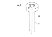
図3〜6は、本書で以下システム10と呼ぶ本システムを示す。
3-6 show this system, hereinafter referred to as
図3〜4bに示す通り、システム10は、筐体12に出入りする異形切開要素16(図4a〜5に示す)の動きを案内するための異形切開要素トラクト14を含む筐体12を含む。十字形の切刃およびトラクトを図4a〜5に示す。他の構成として、直刃、V字形刃だけでなく、3フランジブレード、または制御された切開を組織に形成するのに適した任意の構成をも挙げることができる。筐体12は、通常の当業熟練者に周知の技術を使用して、金属(例えばステンレス鋼)またはポリマー(例えばポリプロピレン)またはそれらの組合せから成形または機械加工することができる。
As shown in FIGS. 3-4b, the
切開要素16はトラクト14に沿って筐体12から外に出て、組織に十字形パターンを切開する。筐体12のヘッド部18は、組織に対して操作角を提供するために(30〜60度)傾斜する。切開要素16は、切開要素16の刃20が動脈の壁を切開することができるが血管の内壁を損傷しない位置までヘッド部18から外に移動する。
The
図5は、筐体12から取り出した切開要素16を示す。十字形の切開要素は、単体として移動する4つの刃を含むが、刃の各々が別々に移動する構成も考えられる。
FIG. 5 shows the cutting
好適な切開角度は45度である。切刃20は、筐体12内または刃20に配置されたストッパによって制限される行程を進む。行程は処理される組織に応じて決定されかつ調整される。動脈の場合、それは典型的には10から20mmの間である。単純直線状切開、またはV字形切開の場合、切開は単一刃構造(1つまたは2つの刃から構成することができる)によって行われる。このタイプの切開は、内腔軸線に対して垂直となる。直線状切開の長さは通常、4〜8mmとなり、刃の厚さは通常〜0.1mmである。より複雑な構成、例えば十字形刃では、45度の切開角度で使用したときに対称的な切開が形成されるように、非対称刃を使用することができる。
A preferred incision angle is 45 degrees. The
切開要素16の刃20は、筐体12の長さだけ延びることができかつガイドワイヤまたは針を受容するように設計された中心穴24をも含む、中心ロッド22の周りに配設される。針および/またはガイドワイヤは、図7a〜cに関連して本書でさらに下述するように、血管に対するシステム10の初期位置決めのために使用することができる。
The
筐体12はまた、閉鎖装置30の(図6に示す)一部を形成するチューブ28を案内するためのチャネル26をも含む。チューブ28は、筐体12のチャネル26から放出されかつ動脈壁を穿通するように設計される。そのような放出は、トリガされたばね要素または放出アームを介して達成することができる。
The
システム10はさらに、切開要素16および閉鎖装置30を別々に操作するための近位ハンドルおよび接続アーム(図示せず)を含む。ハンドルを押し込むことにより、切開要素16およびチューブ28を筐体12から押し出して動脈の壁に押し付けることができる。閉鎖装置30および/または切開要素16はさらに、早期動作を防止するために安全機構を含むことができる。システム10はさらに、切開要素16および/または閉鎖装置30が予め定められた位置を越えて前進するのを防止するための係止機構を含むことができる。この機構は、切開要素16および/または閉鎖装置30が内部動脈組織を偶発的に損傷しないことを確実にする。
The
金属、好ましくはニチノールのヘッド(ワイヤリーダ)および金属またはポリマの縫合糸/ワイヤ/糸(ワイヤテール)から構成されるワイヤとして形成された閉鎖要素が、チューブ28に予め装填される(各チューブ28に1本のワイヤ/縫合糸)。ワイヤリーダは組織を穿通するための組織穿刺ヘッドを含むことができ、あるいはそのような組織穿刺はチューブ28によって達成することができる。ワイヤリーダはさらに、切開要素16の中心ロッド22または刃20に配置することのできる受容器要素と係合するように設計された係合機能(例えば小さいフック)を含む。
A closure element formed as a wire composed of a metal, preferably a nitinol head (wire leader) and a metal / polymer suture / wire / thread (wire tail) is preloaded into each tube 28 (each tube 28). One wire / suture). The wire leader can include a tissue puncture head for penetrating tissue, or such tissue puncture can be accomplished by a
そのような受容器(図示せず)は、動脈の内腔内でワイヤリーダと係合するように構成されたメッシュ、またはワイヤテールを捕捉しかつ切開要素16によって形成されたアクセス部位を介して引き出されるように構成されたフックとすることができる。メッシュまたはフックは、ワイヤリーダと係合するために中心ロッド22から展開して拡張することができる。例えばメッシュ構造は中心ロッド22内に隔離(圧縮)され、(ステントとほぼ同じように)拡張されて網状醸造を形成することができ、それが、フックまたは玉状突起を設けることのできるワイヤリーダを捕獲することができる。ワイヤリーダの捕獲後に、メッシュおよび取り付けられたワイヤを後退させ、アクセス部位から引き出すことができる。
Such a receptor (not shown) may be via a mesh configured to engage the wire leader within the lumen of the artery, or through an access site that captures the wire tail and is formed by the cutting
4本のワイヤを利用する場合、ワイヤテールは、皮膚または動脈の外壁に対するバックストップとして機能するTバーまたはディスク状固定要素で終端させることができる。そのような固定要素は、ワイヤおよび縫合糸と共にチャネル16内に予め装填することができる。固定要素はチューブ28から、その中に設けられたプッシュロッドを介して、または単に(アクセス部位を介して引き出された)ワイヤの自由端を引っ張ることによって、追い出すことができる。ワイヤが上層組織を介して送達される場合、固定要素は、そのような上層組織(例えば皮膚)に対して固定するか、あるいは上層組織を介して送達し、アクセス部位の周りの組織(例えば動脈外壁)に対して展開することができる。
When four wires are utilized, the wire tail can be terminated with a T-bar or disc-like fixation element that acts as a backstop to the skin or the outer wall of the artery. Such anchoring elements can be preloaded into the
2本のワイヤを利用する場合、すなわち(ループ端を筐体12内に隔離して)チューブ28の各対が単一ループワイヤを担持するように2本のワイヤを4つのチューブ28に装填した場合、ワイヤの自由端は組織内に送達され、かつ上述の通り各ワイヤのループが「バックストップ」として機能して回収される。
When two wires are used, ie, two wires are loaded into four
図7a〜cは、動脈40に対するシステム10の動作を示す。
FIGS. 7 a-c show the operation of the
大腿動脈のような動脈は最小組織切開を用いて露出され、動脈の内腔42にガイドワイヤを挿入するための穴を形成するために、針が45度の角度で動脈壁に通される。針が正確に配置されたことは、針穴(図示せず)からの血流によって示される。ガイドワイヤ44は針穴を介して動脈内に挿入され、針は取り出される。
An artery, such as the femoral artery, is exposed using a minimal tissue incision, and a needle is passed through the artery wall at a 45 degree angle to form a hole for insertion of a guide wire into the
システム10の筐体12はガイドワイヤ44(図7bに示す)上に装着され、筐体12のヘッド部18が壁46と完全に接触し、かつ筐体が動脈40に対して約45度傾斜するように、システム10は組織を介して動脈40の壁46の外面上に配置される。
The
チューブ28(図示せず)は壁46に当接する位置まで移動し、ワイヤは壁46を貫通して動脈40の内腔42内に押し込まれる。ワイヤリーダは動脈内に配置されるが、バックストップが依然として筐体12のチャネル26内に維持される状態で、テール部分は動脈壁から突出する。
The tube 28 (not shown) moves to a position where it abuts the
ワイヤリーダが内腔42内に配置された状態で、切開要素16は壁46を介して展開され(筐体12内のトラクト14から押し出され)、組織に十字形切開を形成する。今や動脈40の内腔48内に配置された刃20または中心ロッド22は、動脈40の内腔42内のワイヤリーダと係合する。切開要素16を筐体12内に後退させると、ワイヤは組織切開を介して内腔42から引き出される。形成されたアクセス部位から切開要素をさらに後退させ、かつ/または組織から筐体12を後退させると、ワイヤは組織切開からさらに引き出され、ワイヤテール(および含まれるバックストップ)はチューブ28から解放される。
With the wire leader positioned in the
筐体12を体外に完全に引き出すと、ワイヤのヘッド部が体外に引き出され、バックストップは壁46の外面に対して固定される。
When the
システム10は今や、縁部で動脈内に入り込みかつ切開の中心から外に引き出されたワイヤ縫合糸が各々に取り付けられた三角形の縁部を有する十字形切開を残して、完全に取り出すことができる。ワイヤは、アクセス部位の周りのワイヤの位置に対する各々の識別を可能にするために、個別に色分けすることができる。
The
次いで、縁部および取り付けられたワイヤを内向きに内腔48内に押し込むことによって、切開組織を介して作業シースを挿入することができる。次いで、腹部大動脈瘤(AAA)または経皮的弁置換術(例えばAVR)のような処置を、シースを介して実施することができる。処置の間中、ワイヤの自由リーダ部分は体外に維持される(例えば皮膚切開の周りの皮膚にテープで貼付される)。 The working sheath can then be inserted through the incised tissue by pushing the edge and attached wire inwardly into the lumen 48. A procedure such as an abdominal aortic aneurysm (AAA) or percutaneous valve replacement (eg, AVR) can then be performed through the sheath. During the procedure, the free leader portion of the wire is maintained outside the body (eg, taped to the skin around the skin incision).
処置後に、シースは引き出され、縁部はアクセス部位を部分的に閉鎖するまで引き戻される。次いでワイヤを利用して、アクセス部位が閉鎖され、そこからの血液の漏出が防止される。 After the procedure, the sheath is withdrawn and the edge is withdrawn until the access site is partially closed. The wire is then utilized to close the access site and prevent leakage of blood therefrom.
幾つかの閉鎖スキームを利用することができる。ワイヤは切開の中心からアクセス部位の中心を介して内腔48から退出するので、1つ以上の固定要素(例えば結束リング、クリップ、またはパッチ)をワイヤに沿って体外から動脈壁46に押し付けることができる。固定要素は摩擦、接着剤等を介してワイヤを固定することができ、または代替的にワイヤを固定要素の上から結着することができる。いずれにしても、ワイヤは縁部が互いに切開を中心に押し付けられるように固定される。漏出がもはや検出されなくなるまで縫合糸(およびしたがって切開部位)に圧縮が加えられ、次いでワイヤは固定要素を介して固定され、端部が切断され、組織から取り出される。
Several closure schemes are available. Because the wire exits the lumen 48 from the center of the incision through the center of the access site, one or more anchoring elements (eg, a binding ring, clip, or patch) are pressed along the wire against the
そのような固定要素は、ワイヤを単一の束状に固定するため、またはワイヤ対を固定するために使用することができる。いずれにしても、固定要素は体外からワイヤ上で動脈壁に押し当てられる。押込みは、遠端が固定要素を保持し、ワイヤに沿ってそれを移動させ、動脈壁の部位で解放するように構成された専用工具により達成される。 Such securing elements can be used to secure the wires in a single bundle or to secure a wire pair. In any case, the fixation element is pressed against the artery wall over the wire from outside the body. Pushing is accomplished with a dedicated tool that is configured so that the distal end holds the fixation element, moves it along the wire, and releases it at the site of the arterial wall.
そのような固定要素の利点は、アクセス部位が閉鎖されるときに、ワイヤが組織に過度の引張り力を加えるのを防止することである。 The advantage of such a fixation element is that it prevents the wire from applying excessive tension to the tissue when the access site is closed.
固定要素は、ワイヤをひとまとめに狭持するためのクリップ、またはボタンとすることができる。クリップ/ボタンは、ポリグリコール酸および/またはポリ乳酸単位(例えばPGA、PLA、またはPLGA)から構成されたポリマーのような生体吸収性材料から製造することができる。 The securing element can be a clip or button for holding the wires together. The clip / button can be made from a bioabsorbable material such as a polymer composed of polyglycolic acid and / or polylactic acid units (eg, PGA, PLA, or PLGA).
固定要素の1つの実施例を図19に示す。この図に示すように、固定要素はアクセス部位内に配置される一方、ワイヤ/縫合糸の第1端は固定要素の中心穴に同時挿通され、第2端は(固定要素の位置決めの前または後で)固定要素の上にループされるかまたはそれに取り付けられる。 One example of a securing element is shown in FIG. As shown in this figure, the anchoring element is positioned within the access site while the first end of the wire / suture is simultaneously inserted through the central hole of the anchoring element and the second end (before or after positioning of the anchoring element). Later) looped over or attached to the fixing element.
固定要素のこの例示的構成はディスク形であり、閉鎖に利用されるワイヤ/縫合糸の端部を受け入れるための中心穴を含む。図19の固定要素は、アクセス部位の組織縁部が固定要素の外周に当接するように、アクセス部位内に配置されるように設計されている。ディスクは、その外周に当接する組織縁部が(例えばグロメット形の)外周スロット内に収まるように設計することができる。プラグとして(パッチとしてではなく)機能する固定要素は、閉鎖中に組織に掛かる縫合糸/ワイヤの力を低減しながら、より緊密な封止をもたらす。 This exemplary configuration of the fixation element is disk-shaped and includes a central hole for receiving the end of a wire / suture utilized for closure. The fixation element of FIG. 19 is designed to be placed in the access site such that the tissue edge of the access site abuts the outer periphery of the fixation element. The disc can be designed such that the tissue edge that abuts its outer periphery fits within an outer peripheral slot (eg, grommet shaped). An anchoring element that functions as a plug (not as a patch) provides a tighter seal while reducing the suture / wire force on the tissue during closure.
固定要素のこの構成は次のように使用することができる。アクセス部位から出てくる縫合糸(4〜6本の縫合糸)の端部は、固定要素の中心穴に挿通される。次いで、縫合糸をひとまとめに保持するように中心穴をクリンプ(塑性変形)することができる一方、(中心穴から出てくる)近端は切断されるかあるいはひとまとめに結束される。 This configuration of fixing elements can be used as follows. The ends of the sutures (4-6 sutures) coming out from the access site are inserted through the central hole of the fixing element. The central hole can then be crimped (plastically deformed) to hold the sutures together, while the proximal ends (out of the central holes) are cut or tied together.
縫合糸の両端を静かに(近位方向に)引っ張り、固定要素がアクセス部位の周りの組織と係合する位置まで、要素を(上から押し、縫合糸を引っ張って)アクセス部位内に前進させる。ひとたび要素が所定の位置に着くと、引っ張られた縫合糸端部が要素の上で互いに結束され、動脈組織および閉鎖要素の緊密な接触が達成される一方、縫合糸端部は近位で切断されて結着される。 Gently pull both ends of the suture (proximally) to advance the element into the access site (push from above and pull the suture) until the anchoring element engages the tissue around the access site . Once the element is in place, the pulled suture ends are tied together on the element to achieve intimate contact between the arterial tissue and the closure element, while the suture ends are cut proximally To be bound.
ワイヤを切開部位から引き出すことが好ましいが、システム10の他の構成でワイヤを組織に縫込むことも予想される。そのような場合、閉鎖装置は、ワイヤを動脈壁の内外に挿通させることを可能にする縫込みヘッドを含む。例えば、外側から動脈壁を穿通しかつ外側に引き返す湾曲針を有する縫込みヘッドを使用して、1本以上のワイヤをアクセス部位の周りに縫込むことができる。
While it is preferred to pull the wire out of the incision site, other configurations of the
本システムはまた、アクセス部位を完全に閉鎖するのではなく、むしろアクセス部位の大きさを(例えば6〜8Fに)縮小するために利用することもできることは理解されるであろう。そのような場合、必要な縫合が少なくなり(例えばV字形のアクセス部位切開の各「アーム」に2つの縫い目)、完全な閉鎖は、本システムまたは別個の装置(例えば組織接着剤ディスペンサ)を用いて投与することのできるシーラント、接着剤、またはパッチ/スポンジ/プラグ等を介して達成することができる。 It will be appreciated that the system can also be used to reduce the size of the access site (eg, to 6-8F) rather than completely closing the access site. In such cases, fewer sutures are required (eg, two seams on each “arm” of the V-shaped access site incision) and complete closure uses the system or a separate device (eg, a tissue adhesive dispenser). Can be achieved via sealants, adhesives, patches / sponges / plugs, etc.
したがって、本発明は、アクセス部位の生成および閉鎖のためのシステムを提供する。本システムは、先行技術の手法に比べて次のことを含む幾つかの利点をもたらす。
(i)公知の切開形状は、アクセス部位の拡張および処置中の歪み/断裂を最小化する。
(ii)縫合糸が切開に対して正確に配置されるので、かつ複数の縫合糸が互いに対して正確に配置されるので、正確な閉鎖が可能である。
(iii)閉鎖部位の内腔の残存狭隘を低減する。
(iv)縫合糸の誤配置のリスクを低減する(縫合糸が組織を捕捉しないか、あるいは最小限の組織部分を狭隘化する)。
(v)固定要素は組織に掛かる縫合糸の力を低減し、力の対称性を維持し、かつ縫合糸が組織を断裂させるリスクを最小化する。
Accordingly, the present invention provides a system for access site creation and closure. The system provides several advantages over the prior art approaches, including:
(I) Known incision shapes minimize access site dilation and distortion / rupture during the procedure.
(Ii) Since the suture is accurately positioned with respect to the incision and the plurality of sutures are accurately positioned with respect to each other, accurate closure is possible.
(Iii) Reducing residual narrowing of the lumen at the closed site.
(Iv) Reduce the risk of misplacement of sutures (the sutures do not capture tissue or narrow the minimum tissue portion).
(V) The anchoring element reduces the force of the suture on the tissue, maintains force symmetry, and minimizes the risk that the suture will tear the tissue.
本発明はまた、拡張器および閉鎖装置の機能を組み合わせたシステムをも包含する。 The present invention also encompasses a system that combines the functions of a dilator and a closure device.
したがって、本発明の別の態様では、上述した閉鎖装置は、アクセス部位を生成するために穴を拡張する前または途中に閉鎖要素が穴(例えば針の穿刺穴)の周りの組織に取り付けられるように、拡張器の機能と一体化される。 Thus, in another aspect of the invention, the closure device described above allows the closure element to be attached to tissue around the hole (eg, a needle puncture hole) before or during dilation of the hole to create an access site. And integrated with the function of the dilator.
そのようなシステムは、組織の穴を拡張するように設計された組織拡張要素(例えば円錐形のガイドワイヤ案内拡張器シース)を本書に記載する組織閉鎖装置と(好ましくは単一筐体内に)一体化する。 Such a system includes a tissue expansion element (eg, a conical guidewire guide dilator sheath) designed to expand a tissue hole with a tissue closure device described herein (preferably in a single housing). Integrate.
図16〜18は、本書でシステム100と呼ぶ、アクセス部位を拡張しかつ縫合するためのシステムを示す。
FIGS. 16-18 show a system for expanding and suturing an access site, referred to herein as
システム100は、(中央シャフト103に沿って平行移動することのできる)縫込み部分104を貫通して延びる中央シャフト103に(ヒンジ105を介して)蝶着された拡張器部分102を含む。中央シャフト103は、開放位置(半径方向に拡張した位置‐図18)と閉鎖位置(半径方向に収縮した位置‐図17)との間で作動するように構成された捕集器108を含む。縫込み部分104および拡張器部分102の一部はシース106によって被覆され、それは(近位方向に)引き戻されたときに、中央シャフト103および縫込み部分104に対する拡張器部分102の関着を可能にするヒンジ部分105を露出させる。この関着は、縫込み部分104のアクセス部位における位置決めを可能にする一方、拡張器部分は動脈内にそれに沿って配置される。縫込み部分104は、シース106が開放位置に引き戻されたときに露出され展開される、(針プッシュロッドを内包する)針ガイド110を含む。針ガイド110および内包されるプッシュロッドは、針および取り付けられた縫合糸を動脈壁を通して動脈内腔内に送達するように構成される。捕集器108は、開放位置にあるときに、針および取り付けられた縫合糸を捕捉するように構成される。ひとたび針および取り付けられた縫合糸が送達され、かつ捕捉されると、シース106は閉じて、捕集器108を閉鎖(収縮)位置まで作動させ、それによって縫合糸を保持する。
The
システム100は次のように利用される。動脈は露出され、針または切開要素16により穿刺される。ガイドワイヤが動脈内に挿入され、システム100の拡張器部分102がワイヤ上に配置され、アクセス部位を約12Fの大きさまで拡張するために利用される。縫込み部分104は次いで、中央シャフト103に沿ってアクセス部位に押し付けられ、シース106は引き戻されて、(中央シャフト103に装着され、かつ動脈の内腔内に配置された)捕集器108を開放させ、拡張器部分102と縫込み部分104との間の角度配置(70〜90度)を可能にする。システム100は、捕集器108がアクセス部位の周りで動脈内壁に押し付けられるように、捕集器108が動脈の内壁に並置されるまで引き戻される。次いで針ガイド110が展開され、プッシュロッドを利用して針(および取り付けられた縫合糸)が動脈壁を介して捕集器108内に押し込まれる。
針は所定の角度で動脈壁を穿刺し、所定の位置で捕集器108と係合する(図18参照)。次いで、針および取り付けられた縫合糸が捕集器108に取り付けられたままで、針ガイド110は引き戻される。次いでシース106は閉鎖位置まで押されて捕集器108を閉鎖し、それによって針および取り付けられた縫合糸を中央シャフト103に係止させる。
The needle punctures the artery wall at a predetermined angle and engages the
次いでシステム100は任意選択的に、さらに動脈内に(約100〜200mm)前進して縫合糸の長さを動脈内まで延長させ、縫合糸がアクセス部位に捕獲される野を防止する。縫込み部分104は適位置に維持される一方、中央シャフト103および取り付けられた拡張器部分102は、縫込み部分104の中心を介して体外に引き出される。中央シャフト103を取り出すと、捕集器108に取り付けられた縫合糸端部がアクセス部位を介して体外に引き出され、次いで縫合糸端部は捕集器108から解放することができる。次いで縫込み部分が取り出され、次いでカテーテルをワイヤ上に配置し、かつアクセス部位を介して前進させ、医療処置で使用することができる。ひとたび医療処置が完了すると、体外に配置された縫合糸端部は、上述の通りアクセス部位を閉鎖するために使用することができる。
The
上述したシステムは、アクセス部位をその後の閉鎖または縮小のために準備することを可能にするという点で有利であるが、アクセス部位は、本発明の制御された切開要素を用いて生成されたか否かにかかわらず、代替的手法を介して縮小または閉鎖することもできることは理解されるであろう。 While the system described above is advantageous in that it allows the access site to be prepared for subsequent closure or reduction, whether the access site was created using the controlled dissection element of the present invention. Nevertheless, it will be understood that it may be reduced or closed through alternative approaches.
したがって、本発明の別の態様では、対側閉鎖構成部品を用いて動脈アクセス部位を閉鎖するためのシステムおよび方法を提供する。下でさらに説明する通り、そのような対側閉鎖装置は、同側装置と協働して機能することが好ましい。しかし、ここでは対側構成部品だけの使用も予想されることは理解されるであろう。 Accordingly, another aspect of the present invention provides a system and method for closing an arterial access site using a contralateral closure component. As described further below, such contralateral closure devices preferably function in cooperation with the ipsilateral device. However, it will be understood that the use of only the contralateral component is also envisaged here.
対側装置および同側装置を含むシステムを使用する組織アクセス部位の閉鎖を図20〜25に示す。簡単に言うと、同側構成部品は18Gの針および350ミクロンのガイドワイヤのみならず、12ないし24frの拡張器セットならびに深さマーカ付きの24Fの導入器/シースおよび異形先端付きの14〜18Fのフレックスガイド/シースを含む拡張キットをも含む。先端は同側ガイドワイヤ上を対側ガイドワイヤが通過すること(および両方の同時位置決め)が可能になるように構成され、典型的には長さが約50〜75mmで遠位部直径が約1〜3mm、近位部直径が約6〜18mmの軟質(弾性的)円錐形獅子鼻先端として形作られる。先端はまた、対側ガイドワイヤの通過をさらに容易にするために、その長さに沿ってチャネル/溝をも含むことができる。 Tissue access site closure using a contralateral device and a system including the ipsilateral device is illustrated in FIGS. Briefly, the ipsilateral components are not only 18G needles and 350 micron guidewires, but also 12-24fr dilator sets and 24F introducer / sheath with depth markers and 14-18F with deformed tips. Also included is an expansion kit that includes a flexible guide / sheath. The tip is configured to allow the contralateral guidewire to pass over the ipsilateral guidewire (and simultaneous positioning of both), typically about 50-75 mm in length and about a distal diameter of about Shaped as a soft (elastic) cone-shaped nose tip with 1-3 mm proximal diameter about 6-18 mm. The tip can also include channels / grooves along its length to further facilitate the passage of the contralateral guidewire.
対側構成部品は、針およびガイドワイヤ(標準)、ならびに折畳み構成で4〜5F、開放(展開可能)構成で22〜28Fの展開可能な管状要素を含む。管状要素は典型的には長さが20〜30mmであり、ロール状シート、部分的もしくは完全なカバー付きワイヤメッシュ、または生物分解性材料から構成された固体壁を持つチューブとして構成される。対側構成部品はさらに、予め賦形された先端を持つ6Fのガイドカテーテル、および24〜28Fの外部伸展性バルーン(シリコーン)ならびに任意の小穴閉鎖装置(標準)を含む。 The contralateral component includes a needle and guide wire (standard) and a deployable tubular element of 4-5F in a folded configuration and 22-28F in an open (deployable) configuration. Tubular elements are typically 20-30 mm in length and are configured as rolled sheets, partially or fully covered wire mesh, or tubes with solid walls made of biodegradable material. The contralateral component further includes a 6F guide catheter with a pre-shaped tip, and a 24-28F external extensible balloon (silicone) and an optional eyelet closure device (standard).
本システムは、処置前制御切開の有無に関わらず、22〜28Fのシースと共に使用することができる(図20)。 The system can be used with a 22-28F sheath with or without a pre-procedure controlled incision (FIG. 20).
ひとたび処置が行なわれると、(公知の手法を用いて)同側からのアクセスが達成され、ガイドワイヤは同側腸骨に挿入され、6Fのガイドカテーテルはガイドワイヤ上に配置される一方、22〜28Fのシースおよびワイヤは中間腸骨まで引っ張られる。 Once the procedure has been performed, ipsilateral access is achieved (using known techniques), a guidewire is inserted into the ipsilateral iliac bone, and a 6F guide catheter is placed over the guidewire, while 22 The ~ 28F sheath and wire are pulled to the intermediate iliac.
ひとたびガイドカテーテルが同側腸骨遠端に配置されると、22〜28Fの要素/バルーンを膨張させることによって、安全閉塞が実施される(図21)。 Once the guide catheter is placed at the distal end of the ipsilateral iliac, a safe occlusion is performed by inflating the 22-28F element / balloon (FIG. 21).
次いで22〜28Fの同側シースは完全に後退し、14〜18Fのシース(上述した特殊先端を持つ)は、同側ガイドワイヤ上を案内されて中間腸骨まで戻り、同側アクセス部位穴を越えて対側ガイドワイヤを下方に前進させる(図22)。 The 22-28F ipsilateral sheath is then fully retracted, and the 14-18F sheath (having the special tip described above) is guided over the ipsilateral guidewire back to the intermediate iliac, leaving the ipsilateral access site hole. Beyond, the opposite guide wire is advanced downward (FIG. 22).
ひとたび対側ガイドワイヤが位置に着くと、折曲管状要素(例えばポリマまたは組織カバー付きワイヤ管状要素)は対側アクセス部位から、同側アクセス穴を越えて配置される対側ガイドワイヤ上に挿入される(図23〜24)。上記ステップは全て、バルーン閉塞を用いて血流を監視かつ調整しながら実施される。 Once the contralateral guidewire is in position, the folded tubular element (eg, a polymer or tissue covered wire tubular element) is inserted from the contralateral access site onto the contralateral guidewire that is positioned over the ipsilateral access hole (FIGS. 23 to 24). All of the above steps are performed while monitoring and adjusting blood flow using balloon occlusion.
14〜18Fのフレックスシースは取り外され、穴を跨ぐグラフト位置が確認される。次いでグラフトは(ステントまたはステントグラフトで利用されるものと同様の膨張または解放機構を介して)展開され、同側アクセス部位からの血液が漏出していないか検査することによって、閉鎖の完全性が確認される(図25)。 The 14-18F flex sheath is removed and the graft position across the hole is confirmed. The graft is then deployed (through an expansion or release mechanism similar to that utilized with stents or stent grafts) to verify closure integrity by checking for blood leaking from the ipsilateral access site. (FIG. 25).
次いで対側カテーテルおよびガイドカテーテルはワイヤと共に取り出され、対側アクセス部位は、幾つかの公知の手法のいずれか1つを用いて閉鎖される。次いで同側アクセス部位穴は、縫合糸、パッチ、接着剤等を使用して閉鎖することができる。 The contralateral catheter and guide catheter are then removed with the wire and the contralateral access site is closed using any one of several known techniques. The ipsilateral access site hole can then be closed using sutures, patches, adhesives, and the like.
本明細書中で使用される用語「約」は、±10%を示す。 As used herein, the term “about” refers to ± 10%.
本発明の追加の目的、利点、及び新規な特徴は限定されることを意図されない以下の実施例の精査により当業者に明らかになるだろう。さらに、特許請求の範囲で述べられかつ上述のように記載された本発明の様々な実施形態及び態様の各々は、以下の実施例において実質的な裏付けを見出せる。 Additional objects, advantages, and novel features of the present invention will become apparent to those skilled in the art upon review of the following examples, which are not intended to be limiting. Furthermore, each of the various embodiments and aspects of the invention described in the claims and described above can be found in substantial support in the following examples.
次に下記の実施例が参照されるが、下記の実施例は、上記の説明と一緒に、本発明を非限定様式で例示する。 Reference is now made to the following examples, which together with the above description, illustrate the invention in a non limiting fashion.
アクセス部位の生成および閉鎖をシミュレートするために、ファントムモデルを使用した。シリコーンチューブ50(外径9mm、内径7mm)をニワトリの生の胸部組織51で包み、針および切刃を案内するためのジグ52を用いて、本システムの操作ヘッドをシミュレートした。ジグ52は、45度の組織界面角度ならびに刃および針をそれぞれ案内するための十字形スロット56および4つの穴58を有する円板54としてアルミニウムから機械加工した(図8a〜bおよび9a〜cを参照)。
A phantom model was used to simulate access site generation and closure. A silicone tube 50 (outer diameter 9 mm, inner diameter 7 mm) was wrapped with raw
図8a〜bに示す第1ステップで、針60をジグ52で案内しながら、組織51およびシリコーンチューブ50に45度の角度で挿入した。次いでガイドワイヤを、針を介して、シリコーンチューブ50の内腔内に挿入することができる。次いでガイドワイヤを使用して、縫合糸挿入および切断中にシステムを案内することができる。ファントムモデルでは、本発明の操作ヘッドをシミュレートするためにジグを使用するので、ガイドワイヤの使用は必要ない。
In the first step shown in FIGS. 8a and 8b, the
次いで縫合針62を、組織51を経てシリコーンチューブ50の内腔内に挿入し(図10a〜10c)、切刃64を利用して直線状の半径方向切開パターンをシリコーンチューブの壁に切り込んで、アクセス部位を生成した(図9c)。
The
次いで縫合糸(4〜0)66を、4つの針62を介して、シリコーンチューブ50の内腔内に通した(図10a〜c)。
The suture (4-0) 66 was then passed through the lumen of the
縫合糸66の自由端68を内腔内で捕捉し、中央の針60を介してシリコーンチューブ50および組織51から引き出し、縫合糸66をチューブ50および組織内に維持しながらジグ52を取り外した(図11a〜b)。次いで拡張器70を縫合糸端部68の間に、シリコーンチューブ50の組織51およびアクセス部位72を通して挿入した(図12a〜e)。そのような拡張は切開部位または周囲のシリコーンを目に付くほどには変形しない。アクセス部位の拡張後に、22Fの作業シースをシミュレートするチューブ74(図12eに示す)を、アクセス部位72を介して挿入した。アクセス部位72を閉鎖するために、縫合糸の中央端68を引き出し、ビード76(クリップとして働く)を4つの縫合糸66に沿って組織51を経てシリコーンチューブの外壁78まで通した。(組織51から突出する)縫合糸66の自由端68をきつく引き出して結び、アクセス部位72を閉鎖した(図14a〜d)。図15a〜bは結果的に得られる外部(図15a)および内部閉鎖(図15b)を示す。
The
明確にするため別個の実施形態で説明されている本発明の特定の特徴は単一の実施形態に組み合わせて提供することもできることは分かるであろう。逆に、簡潔にするため単一の実施形態で説明されている本発明の各種の特徴は別個にまたは適切なサブコンビネーションで提供することもできる。 It will be appreciated that certain features of the invention described in separate embodiments for clarity may also be provided in combination in a single embodiment. Conversely, the various features of the invention described in a single embodiment for the sake of brevity may be provided separately or in appropriate subcombinations.
本発明はその特定の実施形態によって説明してきたが、多くの別法、変更および変形があることは当業者には明らかであることは明白である。従って、本発明は、本願の請求項の精神と広い範囲の中に入るこのような別法、変更および変形すべてを包含するものである。本明細書中で言及した刊行物、特許および特許願はすべて、個々の刊行物、特許または特許願が各々あたかも具体的にかつ個々に引用提示されているのと同程度に、全体を本明細書に援用するものである。さらに、本願で引用または確認したことは本発明の先行技術として利用できるという自白とみなすべきではない。 While the invention has been described in terms of specific embodiments thereof, it will be apparent to those skilled in the art that there are many alternatives, modifications, and variations. Accordingly, the present invention is intended to embrace all such alternatives, modifications and variations that fall within the spirit and broad scope of the appended claims. All publications, patents, and patent applications mentioned in this specification are herein incorporated in their entirety as if each individual publication, patent or patent application were specifically and individually cited. It is used in the book. Furthermore, citation or confirmation in this application should not be considered as a confession that it can be used as prior art to the present invention.
Claims (14)
複数の縫合糸を中に含む複数のチューブを含む組織閉鎖装置であって、前記チューブは、前記組織皮弁のそれぞれに対応する前記組織壁の位置に前記複数の縫合糸を取り付けるように構成されている組織閉鎖装置と
を備えた、組織アクセス部位システム。 A tissue dissection element including a plurality of blades configured to create a cross-shaped tissue access site in a tissue wall defined by a plurality of tissue flaps having a triangular shape;
A tissue closure device including a plurality of tubes having a plurality of sutures therein, wherein the tubes are configured to attach the plurality of sutures to positions of the tissue wall corresponding to each of the tissue flaps. A tissue access site system comprising a tissue closure device.
Applications Claiming Priority (5)
| Application Number | Priority Date | Filing Date | Title |
|---|---|---|---|
| US12958308P | 2008-07-07 | 2008-07-07 | |
| US12958908P | 2008-07-07 | 2008-07-07 | |
| US61/129,589 | 2008-07-07 | ||
| US61/129,583 | 2008-07-07 | ||
| PCT/IL2009/000673 WO2010004552A1 (en) | 2008-07-07 | 2009-07-06 | Tissue access site system and method |
Publications (3)
| Publication Number | Publication Date |
|---|---|
| JP2011527226A JP2011527226A (en) | 2011-10-27 |
| JP2011527226A5 JP2011527226A5 (en) | 2012-08-23 |
| JP5695564B2 true JP5695564B2 (en) | 2015-04-08 |
Family
ID=41506732
Family Applications (1)
| Application Number | Title | Priority Date | Filing Date |
|---|---|---|---|
| JP2011517309A Expired - Fee Related JP5695564B2 (en) | 2008-07-07 | 2009-07-06 | Tissue access site system and method |
Country Status (6)
| Country | Link |
|---|---|
| US (2) | US9265497B2 (en) |
| EP (1) | EP2303389A4 (en) |
| JP (1) | JP5695564B2 (en) |
| AU (1) | AU2009269566A1 (en) |
| CA (1) | CA2730173A1 (en) |
| WO (1) | WO2010004552A1 (en) |
Families Citing this family (14)
| Publication number | Priority date | Publication date | Assignee | Title |
|---|---|---|---|---|
| US9265497B2 (en) | 2008-07-07 | 2016-02-23 | Apica Cardiovascular Ireland Limited | Tissue access site system and method |
| US8574245B2 (en) | 2008-08-13 | 2013-11-05 | Silk Road Medical, Inc. | Suture delivery device |
| WO2012178073A1 (en) * | 2011-06-24 | 2012-12-27 | Accessclosure, Inc. | Method and devices for flow occlusion during device exchanges |
| US10434292B2 (en) | 2011-06-24 | 2019-10-08 | Access Closure | Method and devices for flow occlusion during device exchanges |
| US9480497B2 (en) | 2012-02-01 | 2016-11-01 | Angiodynamics, Inc. | Skin nicking device, method and assembly |
| US9532785B2 (en) | 2012-05-09 | 2017-01-03 | Access Closure, Inc. | Method and devices for flow occlusion during device exchanges |
| US20140100646A1 (en) * | 2012-10-09 | 2014-04-10 | Accessclosure, Inc. | Method and devices for flow occlusion during device exchanges |
| US10010317B2 (en) * | 2012-12-05 | 2018-07-03 | Young Jae Kim | Method of improving elasticity of tissue of living body |
| US9301746B2 (en) | 2013-10-11 | 2016-04-05 | Abbott Cardiovascular Systems, Inc. | Suture-based closure with hemostatic tract plug |
| JP7020920B2 (en) * | 2015-02-24 | 2022-02-16 | シルク・ロード・メディカル・インコーポレイテッド | Suture delivery device |
| WO2019136378A1 (en) | 2018-01-05 | 2019-07-11 | Mitrx, Inc. | Pursestring suture retractor and method of use |
| FR3094886A1 (en) * | 2019-04-15 | 2020-10-16 | Paul Pittaluga | Device and method of treating telangiectasia |
| US10813665B1 (en) | 2019-05-03 | 2020-10-27 | Gwbn, Llc | Cutting device and related systems and methods |
| US10603071B1 (en) | 2019-05-03 | 2020-03-31 | Gwbn, Llc | Cutting device and related systems and methods |
Family Cites Families (25)
| Publication number | Priority date | Publication date | Assignee | Title |
|---|---|---|---|---|
| US5372588A (en) * | 1992-11-24 | 1994-12-13 | Farley; Kevin | Trocar having blunt tip |
| US5417699A (en) * | 1992-12-10 | 1995-05-23 | Perclose Incorporated | Device and method for the percutaneous suturing of a vascular puncture site |
| US5830125A (en) | 1993-08-12 | 1998-11-03 | Scribner-Browne Medical Design Incorporated | Catheter introducer with suture capability |
| US5527322A (en) * | 1993-11-08 | 1996-06-18 | Perclose, Inc. | Device and method for suturing of internal puncture sites |
| US5846253A (en) * | 1995-07-14 | 1998-12-08 | C. R. Bard, Inc. | Wound closure apparatus and method |
| US5944730A (en) * | 1997-05-19 | 1999-08-31 | Cardio Medical Solutions, Inc. | Device and method for assisting end-to-side anastomosis |
| US6520988B1 (en) * | 1997-09-24 | 2003-02-18 | Medtronic Ave, Inc. | Endolumenal prosthesis and method of use in bifurcation regions of body lumens |
| US6280460B1 (en) * | 1998-02-13 | 2001-08-28 | Heartport, Inc. | Devices and methods for performing vascular anastomosis |
| US20010041902A1 (en) * | 1998-02-13 | 2001-11-15 | Michael J. Lynch | Anastomotic methods and devices for placing a target vessel in fluid communication with a source of blood |
| US6231518B1 (en) * | 1998-05-26 | 2001-05-15 | Comedicus Incorporated | Intrapericardial electrophysiological procedures |
| US6391048B1 (en) * | 2000-01-05 | 2002-05-21 | Integrated Vascular Systems, Inc. | Integrated vascular device with puncture site closure component and sealant and methods of use |
| WO2001095809A1 (en) * | 2000-06-14 | 2001-12-20 | Sterilis, Inc. | Suturing method and apparatus |
| US7029480B2 (en) * | 2001-01-24 | 2006-04-18 | Abott Laboratories | Device and method for suturing of internal puncture sites |
| US20070073389A1 (en) | 2001-11-28 | 2007-03-29 | Aptus Endosystems, Inc. | Endovascular aneurysm devices, systems, and methods |
| US20040092985A1 (en) * | 2002-09-30 | 2004-05-13 | Ethicon, Inc. | Device for providing thoracoscopic intracardiac access |
| US8394114B2 (en) * | 2003-09-26 | 2013-03-12 | Medtronic, Inc. | Surgical connection apparatus and methods |
| US20050267520A1 (en) | 2004-05-12 | 2005-12-01 | Modesitt D B | Access and closure device and method |
| CA2562862C (en) * | 2004-05-21 | 2013-02-26 | Dvir Keren | Suture device |
| US20060095056A1 (en) * | 2004-10-29 | 2006-05-04 | Peter Douglas | Device for incising a blood vessel |
| US7753935B2 (en) | 2005-04-29 | 2010-07-13 | Vivasure Medical Limited | Interventional medical closure device |
| JP2007185495A (en) * | 2006-01-13 | 2007-07-26 | Olympus Medical Systems Corp | Overtube |
| US7731727B2 (en) | 2006-04-26 | 2010-06-08 | Lsi Solutions, Inc. | Medical instrument to place a pursestring suture, open a hole and pass a guidewire |
| WO2008045703A2 (en) * | 2006-10-09 | 2008-04-17 | Isik Frank F | Vascular access devices and methods of use |
| US8834493B2 (en) | 2006-10-20 | 2014-09-16 | St. Jude Medical, Cardiology Division, Inc. | Device and method for vascular closure |
| US9265497B2 (en) | 2008-07-07 | 2016-02-23 | Apica Cardiovascular Ireland Limited | Tissue access site system and method |
-
2009
- 2009-07-06 US US13/002,767 patent/US9265497B2/en active Active
- 2009-07-06 JP JP2011517309A patent/JP5695564B2/en not_active Expired - Fee Related
- 2009-07-06 WO PCT/IL2009/000673 patent/WO2010004552A1/en active Application Filing
- 2009-07-06 EP EP09794096.9A patent/EP2303389A4/en not_active Withdrawn
- 2009-07-06 AU AU2009269566A patent/AU2009269566A1/en not_active Abandoned
- 2009-07-06 CA CA2730173A patent/CA2730173A1/en not_active Abandoned
-
2016
- 2016-01-20 US US15/002,203 patent/US20160135833A1/en not_active Abandoned
Also Published As
| Publication number | Publication date |
|---|---|
| EP2303389A4 (en) | 2013-12-18 |
| US9265497B2 (en) | 2016-02-23 |
| CA2730173A1 (en) | 2010-01-14 |
| JP2011527226A (en) | 2011-10-27 |
| US20160135833A1 (en) | 2016-05-19 |
| US20110118759A1 (en) | 2011-05-19 |
| WO2010004552A1 (en) | 2010-01-14 |
| AU2009269566A1 (en) | 2010-01-14 |
| EP2303389A1 (en) | 2011-04-06 |
Similar Documents
| Publication | Publication Date | Title |
|---|---|---|
| JP5695564B2 (en) | Tissue access site system and method | |
| JP7020920B2 (en) | Suture delivery device | |
| US6709442B2 (en) | Vascular bypass grafting instrument and method | |
| JP6356665B2 (en) | Vascular closure device and method | |
| DK2793708T3 (en) | DEVICES FOR INCLUDING OR PROMOTING FLUID FLOW | |
| US20080086075A1 (en) | Vascular access devices and methods of use | |
| US11723639B2 (en) | Vascular closure device | |
| JP2008500125A (en) | Suture device | |
| EP1011473A1 (en) | Device and method for suturing tissue | |
| WO2014178046A1 (en) | A shaft-pushed fastenable suture | |
| EP2519161A2 (en) | Closure system and uses thereof | |
| WO2012090069A2 (en) | Surgical closure systems and methods | |
| WO2008027366A2 (en) | Devices and methods for creating and closing controlled openings in tissue | |
| EP2732771A1 (en) | Degradable balloon device for closure of openings in a tissue wall | |
| CN115776873A (en) | Devices and methods for allowing large calibre, septal access and subsequent reentry into the atrium |
Legal Events
| Date | Code | Title | Description |
|---|---|---|---|
| A521 | Request for written amendment filed |
Free format text: JAPANESE INTERMEDIATE CODE: A821 Effective date: 20120220 |
|
| A711 | Notification of change in applicant |
Free format text: JAPANESE INTERMEDIATE CODE: A711 Effective date: 20120220 |
|
| A521 | Request for written amendment filed |
Free format text: JAPANESE INTERMEDIATE CODE: A821 Effective date: 20120220 |
|
| A521 | Request for written amendment filed |
Free format text: JAPANESE INTERMEDIATE CODE: A523 Effective date: 20120705 |
|
| A621 | Written request for application examination |
Free format text: JAPANESE INTERMEDIATE CODE: A621 Effective date: 20120705 |
|
| A131 | Notification of reasons for refusal |
Free format text: JAPANESE INTERMEDIATE CODE: A131 Effective date: 20130913 |
|
| A601 | Written request for extension of time |
Free format text: JAPANESE INTERMEDIATE CODE: A601 Effective date: 20131205 |
|
| A602 | Written permission of extension of time |
Free format text: JAPANESE INTERMEDIATE CODE: A602 Effective date: 20131212 |
|
| A521 | Request for written amendment filed |
Free format text: JAPANESE INTERMEDIATE CODE: A523 Effective date: 20140228 |
|
| A131 | Notification of reasons for refusal |
Free format text: JAPANESE INTERMEDIATE CODE: A131 Effective date: 20140613 |
|
| A521 | Request for written amendment filed |
Free format text: JAPANESE INTERMEDIATE CODE: A523 Effective date: 20140828 |
|
| TRDD | Decision of grant or rejection written | ||
| A01 | Written decision to grant a patent or to grant a registration (utility model) |
Free format text: JAPANESE INTERMEDIATE CODE: A01 Effective date: 20150120 |
|
| A61 | First payment of annual fees (during grant procedure) |
Free format text: JAPANESE INTERMEDIATE CODE: A61 Effective date: 20150206 |
|
| R150 | Certificate of patent or registration of utility model |
Ref document number: 5695564 Country of ref document: JP Free format text: JAPANESE INTERMEDIATE CODE: R150 |
|
| R250 | Receipt of annual fees |
Free format text: JAPANESE INTERMEDIATE CODE: R250 |
|
| R250 | Receipt of annual fees |
Free format text: JAPANESE INTERMEDIATE CODE: R250 |
|
| R250 | Receipt of annual fees |
Free format text: JAPANESE INTERMEDIATE CODE: R250 |
|
| R250 | Receipt of annual fees |
Free format text: JAPANESE INTERMEDIATE CODE: R250 |
|
| R250 | Receipt of annual fees |
Free format text: JAPANESE INTERMEDIATE CODE: R250 |
|
| LAPS | Cancellation because of no payment of annual fees |