JP5693975B2 - Imaging catheter with integrated contrast injector - Google Patents
Imaging catheter with integrated contrast injector Download PDFInfo
- Publication number
- JP5693975B2 JP5693975B2 JP2010550740A JP2010550740A JP5693975B2 JP 5693975 B2 JP5693975 B2 JP 5693975B2 JP 2010550740 A JP2010550740 A JP 2010550740A JP 2010550740 A JP2010550740 A JP 2010550740A JP 5693975 B2 JP5693975 B2 JP 5693975B2
- Authority
- JP
- Japan
- Prior art keywords
- contrast agent
- contrast
- lumen
- imager
- ultrasound
- Prior art date
- Legal status (The legal status is an assumption and is not a legal conclusion. Google has not performed a legal analysis and makes no representation as to the accuracy of the status listed.)
- Expired - Fee Related
Links
Images


Classifications
-
- A—HUMAN NECESSITIES
- A61—MEDICAL OR VETERINARY SCIENCE; HYGIENE
- A61B—DIAGNOSIS; SURGERY; IDENTIFICATION
- A61B8/00—Diagnosis using ultrasonic, sonic or infrasonic waves
- A61B8/06—Measuring blood flow
-
- A—HUMAN NECESSITIES
- A61—MEDICAL OR VETERINARY SCIENCE; HYGIENE
- A61B—DIAGNOSIS; SURGERY; IDENTIFICATION
- A61B8/00—Diagnosis using ultrasonic, sonic or infrasonic waves
- A61B8/12—Diagnosis using ultrasonic, sonic or infrasonic waves in body cavities or body tracts, e.g. by using catheters
-
- A—HUMAN NECESSITIES
- A61—MEDICAL OR VETERINARY SCIENCE; HYGIENE
- A61B—DIAGNOSIS; SURGERY; IDENTIFICATION
- A61B8/00—Diagnosis using ultrasonic, sonic or infrasonic waves
- A61B8/48—Diagnostic techniques
- A61B8/481—Diagnostic techniques involving the use of contrast agent, e.g. microbubbles introduced into the bloodstream
-
- A—HUMAN NECESSITIES
- A61—MEDICAL OR VETERINARY SCIENCE; HYGIENE
- A61M—DEVICES FOR INTRODUCING MEDIA INTO, OR ONTO, THE BODY; DEVICES FOR TRANSDUCING BODY MEDIA OR FOR TAKING MEDIA FROM THE BODY; DEVICES FOR PRODUCING OR ENDING SLEEP OR STUPOR
- A61M37/00—Other apparatus for introducing media into the body; Percutany, i.e. introducing medicines into the body by diffusion through the skin
- A61M37/0092—Other apparatus for introducing media into the body; Percutany, i.e. introducing medicines into the body by diffusion through the skin using ultrasonic, sonic or infrasonic vibrations, e.g. phonophoresis
-
- A—HUMAN NECESSITIES
- A61—MEDICAL OR VETERINARY SCIENCE; HYGIENE
- A61M—DEVICES FOR INTRODUCING MEDIA INTO, OR ONTO, THE BODY; DEVICES FOR TRANSDUCING BODY MEDIA OR FOR TAKING MEDIA FROM THE BODY; DEVICES FOR PRODUCING OR ENDING SLEEP OR STUPOR
- A61M5/00—Devices for bringing media into the body in a subcutaneous, intra-vascular or intramuscular way; Accessories therefor, e.g. filling or cleaning devices, arm-rests
- A61M5/007—Devices for bringing media into the body in a subcutaneous, intra-vascular or intramuscular way; Accessories therefor, e.g. filling or cleaning devices, arm-rests for contrast media
-
- A—HUMAN NECESSITIES
- A61—MEDICAL OR VETERINARY SCIENCE; HYGIENE
- A61M—DEVICES FOR INTRODUCING MEDIA INTO, OR ONTO, THE BODY; DEVICES FOR TRANSDUCING BODY MEDIA OR FOR TAKING MEDIA FROM THE BODY; DEVICES FOR PRODUCING OR ENDING SLEEP OR STUPOR
- A61M5/00—Devices for bringing media into the body in a subcutaneous, intra-vascular or intramuscular way; Accessories therefor, e.g. filling or cleaning devices, arm-rests
- A61M5/14—Infusion devices, e.g. infusing by gravity; Blood infusion; Accessories therefor
- A61M5/168—Means for controlling media flow to the body or for metering media to the body, e.g. drip meters, counters ; Monitoring media flow to the body
- A61M5/172—Means for controlling media flow to the body or for metering media to the body, e.g. drip meters, counters ; Monitoring media flow to the body electrical or electronic
-
- A—HUMAN NECESSITIES
- A61—MEDICAL OR VETERINARY SCIENCE; HYGIENE
- A61B—DIAGNOSIS; SURGERY; IDENTIFICATION
- A61B8/00—Diagnosis using ultrasonic, sonic or infrasonic waves
- A61B8/54—Control of the diagnostic device
- A61B8/543—Control of the diagnostic device involving acquisition triggered by a physiological signal
-
- A—HUMAN NECESSITIES
- A61—MEDICAL OR VETERINARY SCIENCE; HYGIENE
- A61M—DEVICES FOR INTRODUCING MEDIA INTO, OR ONTO, THE BODY; DEVICES FOR TRANSDUCING BODY MEDIA OR FOR TAKING MEDIA FROM THE BODY; DEVICES FOR PRODUCING OR ENDING SLEEP OR STUPOR
- A61M25/00—Catheters; Hollow probes
- A61M25/0021—Catheters; Hollow probes characterised by the form of the tubing
- A61M25/0023—Catheters; Hollow probes characterised by the form of the tubing by the form of the lumen, e.g. cross-section, variable diameter
- A61M25/0026—Multi-lumen catheters with stationary elements
- A61M2025/0037—Multi-lumen catheters with stationary elements characterized by lumina being arranged side-by-side
-
- A—HUMAN NECESSITIES
- A61—MEDICAL OR VETERINARY SCIENCE; HYGIENE
- A61M—DEVICES FOR INTRODUCING MEDIA INTO, OR ONTO, THE BODY; DEVICES FOR TRANSDUCING BODY MEDIA OR FOR TAKING MEDIA FROM THE BODY; DEVICES FOR PRODUCING OR ENDING SLEEP OR STUPOR
- A61M25/00—Catheters; Hollow probes
- A61M25/0021—Catheters; Hollow probes characterised by the form of the tubing
- A61M25/0023—Catheters; Hollow probes characterised by the form of the tubing by the form of the lumen, e.g. cross-section, variable diameter
- A61M25/0026—Multi-lumen catheters with stationary elements
- A61M2025/0039—Multi-lumen catheters with stationary elements characterized by lumina being arranged coaxially
Description
本発明は、画像化カテーテル、特に一体形造影剤インゼクタを備えた画像化カテーテルに関する。 The present invention relates to an imaging catheter, and more particularly to an imaging catheter with an integral contrast agent injector.
〔関連出願の説明〕
本願は、2008年3月13日に出願された米国特許出願第12/048,134号の優先権主張出願であり、この米国特許出願を参照により引用し、その記載内容全体を本明細書の一部とする。
[Description of related applications]
This application is a priority claim application of US patent application Ser. No. 12 / 048,134 filed on Mar. 13, 2008, and this US patent application is incorporated by reference. Part.
血管内超音波法(IVUS)は、血管系内の超音波画像を得るための確立されたツールである。IVUSは、カテーテル利用型変換器を用いて太い血管の管腔及び血管壁の画像を得る方法である。IVUSは、冠動脈内に存在するアテローム硬化プラークのサイズ、構造及び組成に対する見通しを得るための確立されたインターベンション心臓病学的ツールである。 Intravascular ultrasound (IVUS) is an established tool for obtaining ultrasound images within the vasculature. IVUS is a method of obtaining images of the lumen and blood vessel wall of a thick blood vessel using a catheter-based transducer. IVUS is an established interventional cardiological tool to gain insight into the size, structure and composition of atherosclerotic plaques present in the coronary arteries.
超音波造影画像化は、体内の器官、血管又は組織の検出及び画像化を促進するために造影剤を用いている。造影剤は、エコー源性マイクロバブル(微小泡)又は周りの媒体(組織及び血液)の超音波散乱特性とは異なる超音波散乱特性を有する他の物質で構成されるのが良く、それにより、造影剤の入っている器官、血管又は組織の視認性が高められる。超音波造影剤として用いられるのに適した音波反射特性を持つ物体としては、固体粒子及び空気又はガス入りマイクロバブルが挙げられる。造影剤は、典型的には、微小循環系の血管を自由に流れることができるがこれらの中に位置したままになることができるサイズの粒子で構成される。調査中の器官、血管又は組織の視認性を高めることにより、造影剤は、臨床医が疾患又は外傷の存在及び広がりを確認するのを助けることができる。造影画像化により、通常は周りの組織とは識別できない微小構造体の視認及び区別が可能になる。 Ultrasound contrast imaging uses contrast agents to facilitate detection and imaging of internal organs, blood vessels or tissues. The contrast agent may be composed of echogenic microbubbles or other materials having ultrasonic scattering properties that differ from the ultrasonic scattering properties of the surrounding medium (tissue and blood), thereby Visibility of organs, blood vessels or tissues containing the contrast medium is enhanced. Objects having sound reflection properties suitable for use as an ultrasound contrast agent include solid particles and microbubbles containing air or gas. Contrast agents are typically composed of particles of a size that can flow freely through the microcirculatory vessels, but remain in them. By increasing the visibility of the organ, blood vessel or tissue under investigation, the contrast agent can help the clinician confirm the presence and spread of the disease or trauma. Contrast imaging enables visual recognition and differentiation of microstructures that are normally indistinguishable from surrounding tissue.
造影剤マイクロバブルは、薬剤又は他の治療薬を患者の体内に投与するためにも使用できる。薬剤投与用途では、マイクロバブルは、不活性ガスに代えて、薬剤又は治療薬を封入している。マイクロバブルは、静脈内に投与されるのが良く、これらマイクロバブルは、血管系を通って移動する。薬剤は、超音波エネルギー源がマイクロバブルを破裂させて薬剤を放出させるまで、封入されると共に不活性状態のままであり、従って、生物学的には役立たない。 Contrast agent microbubbles can also be used to administer drugs or other therapeutic agents into a patient's body. In drug administration applications, microbubbles enclose drugs or therapeutic agents instead of inert gases. Microbubbles may be administered intravenously, and these microbubbles travel through the vasculature. The drug remains encapsulated and inactive until the ultrasonic energy source ruptures the microbubbles and releases the drug, and therefore is not biologically useful.
造影剤は、主として、非侵襲的又は心臓内超音波画像化法で用いられる。これら方法では、例えば点滴静注(静脈内滴注法)又は注射器により造影剤を血流中に注入する。注入された造影剤は、体内の関心のある領域だけでなく、血管系全体を通って流れる。その結果、関心のある領域を画像化するのに必要な量よりも多量の造影剤を患者の体内に注入しなければならない。これら方法と関連した別の問題は、造影剤の注入を画像化に同期させることが困難なことにある。これは、ひとつには、注入された造影剤が関心のある領域に達するのに要する時間を推定することが困難なことにあり、かかる時間は、2分という長い時間になる場合がある。加うるに、これら方法は、造影剤の注入及び画像化のために2つの別々の器械を用いている。 Contrast agents are primarily used in non-invasive or intracardiac ultrasound imaging methods. In these methods, a contrast medium is injected into the bloodstream by, for example, intravenous drip (intravenous drip method) or a syringe. The injected contrast agent flows through the entire vascular system, not just the region of interest in the body. As a result, a greater amount of contrast agent must be injected into the patient than is necessary to image the area of interest. Another problem associated with these methods is that it is difficult to synchronize contrast agent injection with imaging. This is partly because it is difficult to estimate the time required for the injected contrast agent to reach the region of interest, which can be as long as two minutes. In addition, these methods use two separate instruments for contrast agent injection and imaging.
現在、造影剤は、点滴静注又は注射器若しくは案内カテーテルにより手作業での注入によって投与されている。かかる方法は、一様な濃度を保証するに足るほど正確に血管内の造影剤の量を制御することができない。その結果、造影剤のフレーム間輝度は、血管について互いに異なる超音波画像が取られるとばらつきを生じる場合があり、それにより、超音波画像の解釈が困難になる。 Currently, contrast agents are administered by intravenous infusion or by manual injection with a syringe or guide catheter. Such a method cannot accurately control the amount of contrast agent in the blood vessel enough to guarantee a uniform concentration. As a result, the interframe brightness of the contrast agent may vary when different ultrasound images are taken for blood vessels, which makes it difficult to interpret the ultrasound image.
本明細書において、造影剤の注入を画像化カテーテルに一体化するシステム及び方法が開示される。 Disclosed herein are systems and methods for integrating contrast agent injection into an imaging catheter.
一実施形態では、画像化カテーテルは、カテーテルシース及びイメージャ、例えば超音波変換器を有し、イメージャは、シースに取り付けられても良く、シース内に摺動可能に納められても良い。画像化カテーテルは、造影剤を患者の体内に注入する1つ又は2つ以上の出口ポートを備えた造影剤ルーメンを更に有する。造影剤ルーメンは、カテーテルシースに沿って延び、この造影剤ルーメンは、カテーテルシースの外部に位置しても良く、これに組み込まれても良い。好ましくは、造影剤ルーメンの出口ポートは、カテーテルシースに沿ってイメージャから比較的短い既知の距離、例えば20cm以下のところに位置決めされる。カテーテルは、互いに異なる種類の造影剤を注入するための多数の造影剤ルーメンを有するのが良い。 In one embodiment, the imaging catheter includes a catheter sheath and an imager, such as an ultrasound transducer, and the imager may be attached to the sheath or slidably received within the sheath. The imaging catheter further comprises a contrast lumen with one or more outlet ports for injecting contrast medium into the patient's body. The contrast agent lumen extends along the catheter sheath, which may be located outside or incorporated into the catheter sheath. Preferably, the exit port of the contrast agent lumen is positioned at a relatively short known distance, such as 20 cm or less, from the imager along the catheter sheath. The catheter may have multiple contrast media lumens for injecting different types of contrast media.
一体形造影剤インゼクタを備えた画像化カテーテルは、有利には、造影剤を画像化されるべき領域の近くに局所的に注入することにより患者の体内に注入されることが必要な造影剤の量を減少させる。画像化カテーテルは又、造影剤の注入と画像化の容易な同期を可能にする。これは、造影剤ルーメンの出口ポートがイメージャから短い既知の距離のところに配置されているからであり、それにより、注入された造影剤がイメージャにより画像化されている領域に到達するのに要する時間を推定することが容易になる。加うるに、画像化カテーテルは、造影剤を血管内に直接注入することにより特定の血管内の造影剤の量に対して正確な制御を可能にする。 An imaging catheter with an integral contrast agent injector advantageously has a contrast agent that needs to be injected into the patient's body by locally injecting the contrast agent close to the area to be imaged. Reduce the amount. The imaging catheter also allows easy synchronization of contrast agent injection and imaging. This is because the exit port of the contrast agent lumen is located at a short known distance from the imager, thereby requiring the injected contrast agent to reach the area imaged by the imager. It becomes easy to estimate the time. In addition, imaging catheters allow precise control over the amount of contrast agent in a particular blood vessel by injecting the contrast agent directly into the blood vessel.
一実施形態では、造影剤の注入を画像化に自動的に同期させるために同期コントローラが設けられる。同期コントローラは、造影剤を造影剤ルーメン内に圧送するポンプ、例えば電気ポンプを制御することにより注入流量を制御する。一実施形態では、同期コントローラは、一貫した画像輝度を得るために画像化中、造影剤を一定の流量で注入する。 In one embodiment, a synchronization controller is provided to automatically synchronize contrast agent injection with imaging. The synchronous controller controls the injection flow rate by controlling a pump, such as an electric pump, that pumps the contrast agent into the contrast agent lumen. In one embodiment, the synchronous controller injects contrast agent at a constant flow rate during imaging to obtain consistent image brightness.
別の実施形態では、管理された薬剤投与量を特定の治療部位に投与するために薬剤入りマイクロバブルが超音波画像化と組み合わせた状態で用いられる。この実施形態では、薬剤入りマイクロバブルは、治療部位に送達され、これら薬剤入りマイクロバブルは、高レベル超音波エネルギーを受けてマイクロバブルが破裂し、薬剤が治療部位中に放出される。破裂したマイクロバブルの量及びかくして治療部位中に放出された薬剤の量は、マイクロバブルの破裂の前後に取られた画像を吟味することによって求められる。マイクロバブルを破裂させ、放出される薬剤の量を求めるこのサイクルは、所望の薬剤流量が治療部位に送達されるまで繰り返されるのが良い。 In another embodiment, drug-containing microbubbles are used in combination with ultrasound imaging to administer a controlled drug dose to a specific treatment site. In this embodiment, drug-containing microbubbles are delivered to the treatment site, and these drug-containing microbubbles receive high levels of ultrasonic energy to rupture the microbubbles and release the drug into the treatment site. The amount of ruptured microbubbles and thus the amount of drug released into the treatment site is determined by examining images taken before and after the rupture of the microbubbles. This cycle of rupturing the microbubbles and determining the amount of drug to be released may be repeated until the desired drug flow is delivered to the treatment site.
本発明の他のシステム、方法、特徴及び利点は、以下の図の説明及び詳細な説明を吟味すると当業者には明らかになろう。かかる追加のシステム、方法、特徴及び利点は全て、本明細書の開示内容に含まれ、本発明の範囲内に含まれ、そして添付の特許請求の範囲によって保護されるものである。 Other systems, methods, features and advantages of the present invention will become apparent to those of ordinary skill in the art upon examination of the following drawings and detailed description. All such additional systems, methods, features and advantages are included in the disclosure herein, are included within the scope of the present invention, and are protected by the accompanying claims.
本発明の上述の利点及び目的並びに他の利点及び目的をどのように達成するかをより良好に理解するため、添付の図面に示されている本発明の特定の実施形態を参照して上記において概要説明した本発明の具体的な説明を行う。注目されるべきこととして、図に記載された構成要素は、必ずしも縮尺通りではなく、これとは異なり、本発明の原理を説明するうえで強調がなされている。しかしながら、図面において、互いに異なる図全体に関し同一の参照符号は、対応の部分を示している。しかしながら、同一の部分が常に同一の参照符号で示されているとは限らない。さらに、全ての説明は、相対サイズ、相対形状及び他の詳細な属性が文字通り又は正確ではなく、概略的に示されている場合のある技術的思想を提供するものである。 For a better understanding of how the above and other advantages and objectives of the present invention are achieved, reference is made above to the specific embodiments of the present invention shown in the accompanying drawings. A specific description of the present invention will be given. It should be noted that the components described in the figures are not necessarily to scale, as opposed to being emphasized in describing the principles of the present invention. However, in the drawings, like reference numerals designate corresponding parts throughout the different views. However, the same parts are not always indicated by the same reference numerals. Moreover, all descriptions provide technical ideas that may be shown schematically, rather than literal size, relative shape, and other detailed attributes literally or inaccurate.
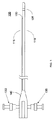
図1は、本発明の実施形態としての一体形造影剤インゼクタを備えた画像化カテーテル105を示している。カテーテル105は、細長いカテーテルシース110及びカテーテルシース110に沿って延びる造影剤ルーメン115を有している。好ましい実施形態では、カテーテルシース110及び造影剤ルーメン115は、血管内における造影剤により促進される画像化のために患者の血管、例えば冠動脈内に挿入されるようになっている。カテーテルは、画像化のために体内の他の通路、例えば食道又は尿道内に挿入されるようになっていてもよい。カテーテルシース110及び造影剤ルーメン115は、種々のポリマー材料、例えばポリテトラフルオロエチレン(PTFE)、ポリエチレン、PEEK、PEBAX等で構成できる。造影剤ルーメン115は、その遠位端部のところに位置していて、造影剤を血管内に注入する出口ポート120を有している。
FIG. 1 shows an
カテーテル105は、超音波イメージャ125を更に有している。超音波イメージャ125は、1つ又は2つ以上の超音波変換器、例えば圧電変換器又は容量型微細加工変換器(CMUT)で構成されるのが良い。超音波イメージャ125は、カテーテルシース110に取り付けられるのが良い。変形例として、超音波イメージャ125は、カテーテルシース110の内部ルーメン内に摺動可能に納められる画像化コアの一部であっても良い。イメージャ125は、側方監視及び/又は前方監視型のものであるのが良い。側方監視及び/又は前方監視型イメージャを有する血管内カテーテルの例は、例えば、2005年4月12日に出願された米国特許出願第11/104,865号明細書(発明の名称:Intravascular Imaging System With Forward Looking Element)に見受けられ、この米国特許出願を参照により引用し、その明細書の記載内容全体を本明細書の一部とする。
The
図3は、カテーテルシース110の内部ルーメン182内に摺動可能に納められた例示の画像化コア175の断面図である。画像化コア175は、駆動ケーブル180及び駆動ケーブル180の遠位端部に取り付けられた超音波イメージャ125を有している。この実施形態では、カテーテルシース110は、超音波画像がシース110を通ることを可能にする音響的に透明な材料で構成されるのが良い。駆動ケーブル180を用いると、超音波イメージャ125をカテーテルシース110内で回転させて血管の断面画像を機械的に走査することができる。駆動ケーブル180は又、超音波イメージャ125をカテーテルシース内で摺動させるのに使用できる。例えば、超音波イメージャ125をカテーテルシース110内で引き戻すと、血管の長さに沿って画像化を行うことができる。矢印190は、引き戻し方向を示している。
FIG. 3 is a cross-sectional view of an
図1に戻ってこれを参照すると、カテーテル105は、ハブ140によりカテーテルシース110の内部ルーメン182に流体結合されたフラッシュポート135を更に有している。フラッシュポート135は、例えば超音波イメージャ125とカテーテルシース110との間の音響結合を促進するために生理的食塩水をカテーテルシース110の内部ルーメン182内に注入するよう使用できる。カテーテル105は、造影剤ルーメン115に流体結合されていて、造影剤ルーメン115を経て造影剤を血管内に注入する造影剤注入ポート130を更に有している。造影剤ポート130は、生理的食塩水をカテーテル内にフラッシュするために一般的に用いられるのと同一形式のポートを用いることができる。造影剤を注射器により手動で、電気ポンプにより電気的に、加圧ブラダにより又は他の手段によって造影剤ポート130内に注入することができる。出口ポート120から血管内への造影剤の注入流量は、造影剤ポート130内への造影剤の注入流量を制御することにより正確に制御できる。造影剤ルーメン115の出口ポート120は、イメージャ125から近位側に位置した状態で示されているが、出口ポート120は、イメージャ125から遠位側に配置されていても良い。
Referring back to FIG. 1, the
好ましい実施形態としての画像化カテーテル105は、点滴静注又は注射器により造影剤を関心のある領域から遠ざかって配置されている注入箇所のところで患者の体内に注入する先行技術の方法と比べて幾つかの利点をもたらす。これら先行技術の方法では、患者の循環系は、注入された造影剤を関心のある領域に運ぶだけでなく、血管系全体にわたって注入造影剤を分布させる。その結果、関心のある領域を局所的に画像化するのに必要な量よりも多量の造影剤を患者の体内に注入しなければならない。画像化カテーテル105は、造影剤をカテーテル105の出口ポート120から関心のある領域の近くに局所的に注入することにより患者の体内に注入される必要のある造影剤の量を減少させる。例えば、カテーテル105により、造影剤を関心のある領域と同一の血管構造、例えば動脈内に注入することができる。
The
画像化カテーテル105は又、造影剤の注入と画像化の同期を容易にすることができる。これは、カテーテルルーメン115の出口ポート120がイメージャ125から短い既知の距離、例えば20cm以下のところで造影剤を注入するからであり、それにより、造影剤がイメージャ125により画像化されている関心のある領域に達するのに要する時間を推定することが非常に容易になる。関心のある領域の存在場所を突き止めるために非造影画像化法を用いることによりイメージャ125を関心のある領域に位置合わせすることができる。次に、例えば関心のある領域内の微細構造体を画像化するために造影画像化法を実施するのが良い。摺動可能な画像化コア175に関し、シース110に沿う出口ポート120の既知の位置を用い、そしてカテーテルシース110内における画像化コア175の相対位置をモニタして出口ポート120との距離を求めることができる。
The
画像化カテーテル105は又、造影剤を血管内に直接注入することにより血管内における造影剤の量に対する正確な制御を可能にする。点滴静注又は注射器により造影剤を注入する先行技術の方法では、特定の血管内における造影剤の量を制御することは困難である。というのは、注入された造影剤は又、血管系全体にわたり他の血管に流れるからである。造影剤の量を制御して得られる利点は、或る特定の量の血液が引き続き下流側の組織に流れ(X線造影剤の注入又は生理的食塩水のフラッシュとは異なり)、それにより、虚血に起因した下流側の組織の損傷を最小限に抑えるようにするよう血流中の造影剤の量を制御することができるということにある。
The
画像化カテーテル105は、血管内における易損性プラーク、血管の直径、血管と関連した脈管の脈管等の造影剤による画像化の促進のために使用できる。画像化カテーテル105は又、血液を周りの組織に供給する微小血管内への血管からの造影剤の灌流を画像化することにより周りの組織の造影剤による画像化の促進のためにも使用できる。画像化カテーテル105は又、例えば組織キャラクタリゼーションのために標的造影剤を血管内に注入して或る特定の種類の組織を画像化するためにも使用できる。これを行うため、標的造影剤は、関心のある組織のレセプタに引き付けられるリガンドを含む場合がある。画像化カテーテル105は又、薬剤又は他の治療薬を含む造影剤を注入するためにも使用できる。例えば、造影剤は、十分に高い超音波エネルギーを受けた場合に破裂して薬剤を放出する薬剤含有マイクロバブル(微小泡)を含むのが良い。以下において、薬剤入りマイクロバブルを用いて薬剤を患者の体内に投与する方法について更に説明する。画像化カテーテル105は又、心臓の心筋層及び体内の他の構造体を画像化するためにも使用できる。
The
画像化カテーテル105は又、血管内における血液の流量を測定するために使用できる。これは、出口ポート120からイメージャ125への造影剤の通過時間を測定し、この通過時間を出口ポート120と造影剤ルーメン115との間の既知の距離で除算することにより実施できる。次に、図3を参照して、例示の実施形態としての血液流量の測定方法について説明する。この実施形態では、造影剤のボーラス(図示せず)をイメージャ125の上流側で出口ポート120から血管内に放出する。矢印185は、血液の流れ方向を示しており、この血液の流れは、出口ポート120からの造影剤のボーラスをイメージャ125まで運ぶ。次に、イメージャ125を作動させて、ボーラスがイメージャ125の超音波場を通ることにより生じる信号強度の増大を検出し、従って、出口ポート120からイメージャ125までのボーラスの通過時間を求める。血管を通る血液の流量を求めることにより、血管の健常性を評価する手段が得られる。流量の測定箇所に応じて、これは、心拍出量、部分フローリザーブ(flow reserve)、冠動脈フローリザーブ又は他の流れに関連した生理的目的を評価するために使用できる。造影剤を用いて血液流量を測定するやり方の細部は、2005年1月14日に出願された国際出願の国際公開第2005/070299号パンフレット(発明の名称:Methods and Apparatus for Medical Imaging)に見受けられ、この国際公開を参照により引用し、その明細書の記載内容全体を本明細書の一部とする。
The
他の特性を計算し又は観察するために造影画像化を利用することができる。例えば、血液流量を計算するには、造影剤のパルスを血流中に注入し、超音波画像化を用いて所与の期間内においてマイクロバブルの体積を測定して血液流量を計算するのが良い。造影画像化を用いると、血管壁中の微小血管密度を計算することができ、血液速度を計算することができ、そして狭窄部の近くの血液速度、狭窄部の内部の血液速度及び狭窄部の遠位側の血液速度を測定することにより狭窄具合(血管の細くなり具合)を計算することができる。また、造影画像化を用いると、造影剤密度の検出により管腔境界部を確かめることができる。 Contrast imaging can be used to calculate or observe other characteristics. For example, to calculate blood flow rate, a pulse of contrast agent is injected into the bloodstream and the volume of microbubbles is measured within a given period using ultrasound imaging to calculate blood flow rate. good. With contrast imaging, the microvessel density in the vessel wall can be calculated, the blood velocity can be calculated, and the blood velocity near the stenosis, the blood velocity inside the stenosis and the stenosis By measuring the blood velocity on the distal side, the degree of stenosis (the degree of blood vessel narrowing) can be calculated. Also, using contrast imaging, the lumen boundary can be ascertained by detecting contrast agent density.
図4は、例示の実施形態としてのインフレート可能/デフレート可能バルーン195を有する画像化カテーテル105を示している。この実施形態では、バルーン195は、出口ポート120とイメージャ125との間に配置され、このバルーンは、カテーテルシース110内のインフレーションルーメン(図示せず)を経てインフレーション流体をバルーン195内に注入することによりインフレートされる。一実施形態では、バルーン195は、関心のある領域中の造影剤の高い濃度を生じさせるために使用される。これは、バルーン195を図4に示されているように血管170内でインフレートさせ、そして造影剤を出口ポート120から血管内に注入することにより行われる。インフレート状態のバルーン195は、血液の流れを一時的に遮断し、それにより造影剤の高い濃度がバルーン195の背後に生じるようにする。次に、バルーン195をデフレートさせて造影剤の高い濃度を解除し、造影剤は、血液の流れによって、イメージャ125の画像化場内の関心のある領域まで運ばれる。また、バルーン195は、ステントを血管内に配備し、血管内のプラークを溶解させ又は他の目的を果たすために使用できる。
FIG. 4 illustrates an
図1は、1つの造影剤ルーメン115を備えた画像化カテーテル105を示しているが、画像化カテーテル105は、多数の造影剤ルーメンを有しても良い。例えば、画像化カテーテル105は、互いに異なる種類の造影剤を血管内に注入するために多数の造影剤ルーメンを有するのが良い。例えば、1つの造影剤ルーメンは、薬剤の入っていないマイクロバブルを血管内に注入して血管を画像化すると共に治療のための領域、例えばアテローム硬化病変部を識別するために使用できる。この場合、別の造影剤ルーメンは、薬剤入りマイクロバブルを血管内に注入して薬剤を治療領域に投与するために使用できる。これら実施形態では、カテーテル装置は、各造影剤ルーメンについてそれぞれ1つずつの複数の造影剤注入ポート130を有するのが良い。
Although FIG. 1 shows an
さらに、造影剤ルーメン115は、カテーテルシースの外部に位置しても良く又はカテーテルシース内に組み込まれていても良い。図5a〜図5cは、画像化カテーテル205の例示の実施形態を示しており、この場合、造影剤ルーメン222は、カテーテルシース215内に組み込まれている。この例示の実施形態では、造影剤ルーメン222は、図5b及び図5cに示されているように画像化コア175を受け入れる作業ルーメン227を包囲している。この例示の実施形態では、カテーテル205は、カテーテルシース215の周囲に沿って配置された造影剤ルーメン222のための複数の出口ポート220を有している。出口ポート220の環状配置により、カテーテルシース215の周囲に沿う造影剤の一様な注入が可能になる。好ましくは、造影剤ルーメン222は、カテーテルシース215の出口ポート220を越えて延びることはない。出口ポートの種々の数及び/又は配置状態は、所望の注入パターンに応じて採用可能である。例えば、出口ポートは、カテーテル周囲回りに螺旋に沿って配置されても良い。
Further, the
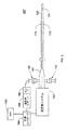
図2は、例示の実施形態としての造影剤の注入を画像化に同期させる画像化カテーテル装置107を示している。カテーテル装置107は、カテーテル105の超音波イメージャ125を伝達パルスにより駆動し、イメージャ125からのエコー信号を処理して超音波画像にするための超音波システム150を有している。イメージャ125は、カテーテル105の端部に固定されても良く、或いは、カテーテルシース110内に納められた画像化コア175の端部に取り付けられても良い。イメージャ125は、1つの変換器又は変換器アレイを有するのが良い。画像化コア実施形態に関し、超音波システムは、画像化コア175をカテーテルシース110内で回転させたり長手方向に並進させたりするモータ駆動ユニット(MDU)を有するのが良い。カテーテル装置107は、造影剤リザーバ155及び造影剤ポート130に流体結合されたポンプ156を更に有する。ポンプ156は、造影剤を電気信号に基づいてリザーバ155から送り出す電気ポンプから成るのが良い。カテーテル装置107は、造影剤の注入を画像化に同期させるよう超音波システム150及びポンプ156を電気的に制御する同期コントローラ160を更に有している。同期コントローラ160は、同期を行うための命令を実行するプロセッサを有するのが良く、かかる同期コントローラを超音波システム150に組み込むのが良い。例示の実施形態では、同期コントローラ160は、ポンプ156がリザーバ155から造影剤を送り出す流量及びかくして造影剤の注入流量を制御する。同期コントローラ160は又、イメージャ125からの画像の収集を制御することができる。画像化コア実施形態に関し、コントローラ160は又、画像化コア175の回転速度及び/又はカテーテルシース110内における画像化コア175の引き戻し速度を制御することができる。
FIG. 2 illustrates an
次に、引き戻し手順中に造影剤の注入を画像化に同期させる方法について説明する。この実施形態では、同期コントローラ160は、イメージャ125を作動させ、イメージャ125を超音波システム150のMDUにより例えば一定の速度で引き戻す。イメージャ125が引き戻されていると、イメージャ125は、血管の断面画像を例えば等間隔で収集することができる。引き戻し手順は、引き戻しの速度及び画像化されている血管の長さに応じて数分間続く場合がある。引き戻し手順中、同期コントローラ160は、造影剤を血管内に一様な流量で注入するようポンプ156を制御するのが良い。引き戻し中における造影剤の一様な注入により、血液中における造影剤の濃度が一層一様になる。この結果、引き戻しの長さ全体に沿って一様な造影画像化が行われる。この実施形態では、出口ポート120は、カテーテルの近位端部よりに十分遠くに配置されても良く、その結果、出口ポート120は、引き戻し全体を通じてイメージャ125の近くに位置したままである。
Next, a method for synchronizing contrast injection with imaging during the pullback procedure will be described. In this embodiment, the
一実施形態では、同期コントローラ160は、造影剤を所与の期間にわたり血管内に注入し、その後、引き戻しを開始して周りの組織が造影剤を吸収することができるようにすると共に周りの組織中の造影剤の濃度が安定状態に達することができるようにする。かかる期間は、周りの組織に関する吸収時間の所定の推定値又は測定値に基づくのが良い。代表的には、微小血管内における血液の流量は、血管内の場合よりも典型的には10〜20倍遅い。かかる期間は又、初期造影剤注入中にイメージャ125により収集された画像を分析することによりリアルタイムで決定できる。この例では、周りの組織中への造影剤の吸収は、造影剤の存在により超音波画像中に明るく見える周りの組織の領域に基づいて決定できる。この分析は、超音波システム150に組み込まれている画像プロセッサからの超音波画像を受け取ることができる同期コントローラ160によって実施されるのが良い。
In one embodiment, the
カテーテル装置205は、造影剤が点滴静注又は注射器若しくは案内カテーテルによる手動注入によって患者の体内に注入される先行技術の方法と比べて有利である。これら先行技術の方法では、一様な濃度を保証するに足るほど正確に血管内の造影剤の量を制御することが困難である。その結果、造影剤のフレーム間輝度は、血管について互いに異なる超音波画像が取られるとばらつきを生じる場合があり、それにより、超音波画像の解釈が困難になる。カテーテル装置205は、引き戻し手順全体にわたり血液中の造影剤の一様な濃度を提供することによってこの問題を解決する。
The
例示の実施形態では、同期コントローラ160は、イメージャ125からの画像の収集を患者の心拍周期(心臓周期)に同期させるよう電気心電図(EKG)モニタ163に結合されている。各心拍周期中、血管は、心臓のポンプ作用により拡張したり収縮したりする。結果的に生じる血管の画像の心拍運動を減少させるには、画像を心拍周期中の同一位相で収集するのが良い。これを行うため、EKGモニタ163は、所望の位相が各心拍周期中で生じる時期を指示する信号を同期コントローラ160に送るのが良く、そして同期コントローラ160は、信号により所望の位相が生じたことが分かると、画像収集及び/又は造影剤注入をトリガするのが良い。
In the exemplary embodiment,
同期コントローラ160は又、超音波画像中の造影剤の輝度に基づいて注入流量を制御することができる。例えば、同期コントローラ160は、超音波画像プロセッサからの画像輝度をモニタすることができる。画像輝度が低くなると、コントローラ160は、造影剤の注入流量を増大させるのが良く、画像輝度が高くなると、コントローラ160は、注入流量を減少させるのが良い。かくして、造影剤の注入流量を画像フィードバックに基づいて調節して超音波画像中に一様な輝度を維持することができる。
The
また、造影剤注入を特定の血圧に同期させることができる。この実施形態では、例えば圧力ワイヤを用いて圧力を測定することができる。また、造影剤注入を特定の血液流量に同期させることができる。 Also, contrast agent injection can be synchronized to a specific blood pressure. In this embodiment, the pressure can be measured using, for example, a pressure wire. Also, contrast agent injection can be synchronized to a specific blood flow rate.
造影剤を注入パルスの状態で、例えば方形波(即ち、所与の期間にわたり一様な注入)、傾斜したパルス又は他の形状のパルスの状態で注入することができる。注入パルスに関し、画像収集を注入の始めに(又は一定の遅延後に)又は注入の終わりに(一定の遅延後に)トリガするのが良い。また、例えば、非一様な注入パルスに関し、画像の収集を注入パルスのピークで(又は一定の遅延後に)トリガすることもできる。複雑なパルス形状に関し、画像化を任意の注入時点で又は一定の遅延後に後でトリガしても良い。 The contrast agent can be injected in the form of an injection pulse, for example in the form of a square wave (ie, a uniform injection over a given period of time), a tilted pulse or other shaped pulse. For injection pulses, image acquisition may be triggered at the beginning of the injection (or after a certain delay) or at the end of the injection (after a certain delay). Also, for example, for non-uniform injection pulses, image acquisition can be triggered at the peak of the injection pulse (or after a certain delay). For complex pulse shapes, imaging may be triggered later at any injection time or after a certain delay.
次に図6を参照して薬剤入りマイクロバブルを用いて制御された投与量の薬剤又は他の治療薬を治療部位に局所的に送達する方法について説明する。図6は、治療部位305のところに位置決めされた血管内のカテーテルの一例を示している。治療部位305は、例えば、破裂して治療されないままで放置された場合には凝血塊を生じさせる場合のあるアテローム硬化病変部であるのが良い。この実施形態では、薬剤入りマイクロバブルは、これらが十分に高い超音波エネルギー及び/又は或る特定の周波数範囲内の超音波エネルギーを受けると、破裂して薬剤を放出するようになっている。マイクロバブルを破裂するには十分ではない低レベル超音波エネルギーを用いて治療部位内の薬剤入りマイクロバブルを画像化することができる。かかる薬剤入りマイクロバブルは、或る特定の種類の組織を標的とする標的マイクロバブルであるのが良い。
Next, a method for locally delivering a controlled dose of drug or other therapeutic agent to the treatment site using drug-containing microbubbles will be described with reference to FIG. FIG. 6 shows an example of an intravascular catheter positioned at the
先ず最初に血管を画像化し、結果的に得られた画像を分析して治療されるべき領域を突き止めることによって薬剤の投与前に治療部位305を識別するのが良い。例えば薬剤の入っていないマイクロバブル又は非造影剤を用いて血管を画像化することができる。治療部位を識別した後、図7に示されている流れ図に記載された方法を用いて制御された投与量の薬剤又は治療薬を治療部位305に投与するのが良い。
The
次に図7の流れ図を参照すると、ステップ705において、カテーテルを用いて治療部位305を含む血管を画像化する。これは、イメージャ125を引き戻し、血管に沿う互いに異なる位置で断面画像を収集することにより実施できる。次に、超音波コンソールは、画像を集めて血管の立体(3次元)画像を作ることができる。
Referring now to the flowchart of FIG. 7, in
ステップ710において、薬剤又は治療薬の入ったマイクロバブルを治療部位305の近くで血管内に注入する。好ましくは、薬剤入りマイクロバブルを治療部位305の上流側に放出する。薬剤入りマイクロバブルは、治療部位305中に灌流し、それにより治療部位305のエコー中心性(echocentricity)が増大する。
In
ステップ715において、マイクロバブルが治療部位305中に灌流しているときにカテーテルを用いて治療部位305を画像化する。治療部位305中へのマイクロバブルの灌流により、治療部位305の画像輝度が高くなる。かかる画像輝度を用いると、治療部位305中の未放出薬剤の濃度を推定することができる。これは、画像輝度が治療部位305中のマイクロバブルの濃度の関数だからである。画像輝度が高ければ高いほど、マイクロバブルの濃度がそれだけ一層高く、それ故に、マイクロバブルに入っている薬剤の量がそれだけ一層多い。好ましくは、マイクロバブルを破裂させるには不十分な低レベル超音波エネルギーを用いて治療部位305を画像化する。治療部位305の画像輝度をモニタして薬剤の入っているマイクロバブルの所望の濃度に達した時期を求める。
In
ステップ720において、所望の濃度に達すると、イメージャ125を、治療部位305内のマイクロバブルを破裂させるのに十分なエネルギーレベルまで付勢し、それによりマイクロバブルに入っている薬剤を治療部位305中に放出する。イメージャ125を付勢してマイクロバブルを治療部位305の長さ全体に沿って破裂させながらイメージャ125を引き戻すのが良い。
In
ステップ725において、イメージャ125を付勢した後に治療部位305を画像化して付勢後におけるマイクロバブルの濃度を求める。追加のマイクロバブルがマイクロバブルの破裂時点と付勢後画像の収集時点との間で治療部位305内に灌流することができるので、例えば治療部位305中へのマイクロバブルの灌流流量に基づいて付勢後マイクロバブル濃度を調節してこれを考慮に入れるのが良い。
In
ステップ730において、マイクロバブルの破裂により治療部位305中に放出された薬剤投与量を推定する。これは、付勢後マイクロバブル濃度を付勢前マイクロバブル濃度から差し引いて治療部位305中に放出された薬剤濃度を求め、そして治療部位305の容積を用いて薬剤投与量を求めることによって実施できる。治療部位305の立体超音波画像に基づいて治療部位305の容積を推定することができる。
In
ステップ735において、放出された薬剤の投与量を記録し、そして治療部位305に投与されるべき所望の全投与量と比較する。所望の全投与量に達していない場合、ステップ705〜735を繰り返し実施し、ついには所望量の薬剤が治療部位305に投与されるようにするのが良い。
In
したがって、薬剤投与法により、外科医は、制御された薬剤投与量を体内の特定の治療部位305により正確に投与することができる。さらに、薬剤投与方法により、治療部位305の外部に位置する体の他の領域に送り出される薬剤の量が減少する。これは、薬剤入りマイクロバブルが治療部位305の近くで局所的に注入され、治療部位305内で制御可能に破壊されて薬剤が治療部位305中に放出されるからである。治療部位305への薬剤の標的投与は、例えば、薬剤が周りの健常な組織に対して有害である場合に重要である。
Thus, drug administration methods allow the surgeon to accurately administer a controlled drug dose at a
薬剤投与法は、造影剤マイクロバブルの濃度を造影剤の投与前後における反射超音波エネルギーの比較により分析的に求めることができるという原理に基づいている。マイクロバブルの濃度を知ることにより、マイクロバブルの個数及びかくしてマイクロバブル内に入っている薬剤又は治療薬の量の推定値を算出することができる。薬剤又は治療薬は、マイクロバブルが破壊されるまで不活性なので、制御された超音波を短いパルスで利用すると、マイクロバブルを小刻みに破裂させることができ、そしてマイクロバブルの破裂の前後における画像化を用いて治療部位中に放出された薬剤の量を求めることができる。このサイクルは、適正な投与量の薬剤又は治療薬が投与されるまで続けられるのが良い。 The drug administration method is based on the principle that the concentration of contrast agent microbubbles can be analytically determined by comparing reflected ultrasonic energy before and after administration of the contrast agent. By knowing the concentration of microbubbles, an estimate of the number of microbubbles and thus the amount of drug or therapeutic agent contained in the microbubble can be calculated. Drugs or therapeutics are inactive until the microbubbles are destroyed, so using controlled ultrasound in short pulses can burst microbubbles in small increments and imaging before and after microbubble rupture Can be used to determine the amount of drug released into the treatment site. This cycle may be continued until the proper dose of drug or therapeutic agent is administered.
一体形インゼクタを備えた画像化カテーテル又は別個の注入装置を用いて薬剤入りマイクロバブルを患者の体内に注入することができる。例えば、別個の案内カテーテルを用いて又は外部手段、例えば点滴静注又は注射器によってマイクロバブルを注入することができる。また、同一の変換器又は種々の変換器を用いてマイクロバブルを画像化したり破壊したりすることができる。さらに、薬剤入りマイクロバブルは、周波数発生非線形応答を示すマイクロバブルから成っていても良い。これにより、例えば基本周波数(即ち、伝送信号の周波数)の超音波を濾波するフィルタを用いてマイクロバブルから反射された超音波を周りの組織から反射された超音波から隔離することができる。例えば、マイクロバブルは、ハーモニックマイクロバブル、サブハーモニックマイクロバブル等から成っていても良い。 Medicinal microbubbles can be injected into the patient's body using an imaging catheter with an integral injector or a separate injection device. For example, the microbubbles can be injected using a separate guide catheter or by external means such as intravenous infusion or a syringe. Also, microbubbles can be imaged or destroyed using the same transducer or various transducers. Furthermore, the drug-containing microbubbles may consist of microbubbles that exhibit a frequency-generated nonlinear response. Thereby, for example, the ultrasonic wave reflected from the microbubbles can be isolated from the ultrasonic wave reflected from the surrounding tissue by using a filter that filters the ultrasonic wave having the fundamental frequency (that is, the frequency of the transmission signal). For example, the microbubble may be composed of a harmonic microbubble, a subharmonic microbubble, or the like.
上記説明において、本発明の特定の実施形態を参照して本発明を説明した。しかしながら、本発明の広い精神及び範囲から逸脱することなく、かかる実施形態の種々の改造例及び変更例を想到できることは明らかであろう。例えば、好ましい実施形態では超音波画像化を用いたが、本発明は、造影剤を用いる他形式の画像化に利用できる。別の例として、読者は、本明細書において説明したプロセス作用の特定の順序及び組み合わせは、例示に過ぎず、別の又は追加のプロセス作用或いはプロセス作用の別の組み合わせ又は順序を用いて本発明を実施できることを理解すべきである。別の例として、一実施形態の各特徴を別の実施形態に示されている他の特徴と組み合わせたりこれにマッチさせたりすることができる。加うるに且つ自明なこととして、特徴を所望に応じて追加し又は除くことができる。したがって、本発明は、添付の特許請求の範囲及びこれらの均等範囲に基づく場合を除き、制限されるものではない。 In the foregoing description, the invention has been described with reference to specific embodiments of the invention. However, it will be apparent that various modifications and changes may be made to such embodiments without departing from the broad spirit and scope of the invention. For example, while preferred embodiments used ultrasound imaging, the present invention can be used for other types of imaging using contrast agents. As another example, the reader is aware that the specific order and combinations of process actions described herein are exemplary only, and that the invention may be used with other or additional process actions or other combinations or orders of process actions. It should be understood that can be implemented. As another example, each feature of one embodiment can be combined with or matched with other features shown in another embodiment. In addition, and obviously, features can be added or removed as desired. Accordingly, the invention is not limited except as by the appended claims and their equivalents.
Claims (14)
前記カテーテルシースの中に納められ、超音波を放出し且つ反射超音波を受け取ることにより超音波画像を取得する超音波イメージャと、
近位端部及び遠位端部を備え、前記カテーテルシースに沿ってその外部に延びるとともに、遠位端部に出口ポートを有する造影剤ルーメンと、
前記造影剤ルーメンの前記近位端部に流体結合されたポンプと、
前記造影剤ルーメンの前記出口ポートと前記超音波イメージャとの間に位置するインフレート可能バルーンであって、血液の流れを遮断するように血管内でインフレート可能であり、前記インフレート可能バルーンのデフレートと前記高い濃度の造影剤の解放の後に、前記造影剤ルーメンから解放された高い濃度の造影剤がつくり出されるのを許すように構成された、インフレート可能バルーンと、
前記超音波イメージャに結合されていて、前記超音波イメージャを駆動し、前記イメージャからの信号を受け取る超音波システムと、
前記ポンプ及び前記超音波システムに結合されていて、前記出口ポートからの造影剤の注入を前記イメージャによる画像の取得に同期させるコントローラであって、画像輝度データ、血圧、または血液流量に基づいて、前記ポンプを用いて前記造影剤の注入流量を調整するよう構成されたコントローラと、を有する、造影画像化システム。 An elongate catheter sheath having a closed distal end and an acoustically transparent material that allows ultrasound images to pass through the catheter sheath;
An ultrasound imager that is contained within the catheter sheath and that acquires ultrasound images by emitting ultrasound and receiving reflected ultrasound;
A contrast lumen having a proximal end and a distal end, extending outwardly along the catheter sheath and having an outlet port at the distal end;
A pump fluidly coupled to the proximal end of the contrast lumen;
A inflatable balloon positioned between the outlet port and the ultrasound imager of the contrast medium lumen, intravascular to block the flow of blood is possible blown, the inflatable balloon An inflatable balloon configured to allow a high concentration of contrast agent released from the contrast agent lumen to be created after deflation and release of the high concentration contrast agent;
An ultrasound system coupled to the ultrasound imager, driving the ultrasound imager and receiving signals from the imager;
A controller coupled to the pump and the ultrasound system for synchronizing injection of contrast agent from the outlet port with acquisition of an image by the imager, based on image luminance data, blood pressure, or blood flow rate; A contrast imaging system comprising: a controller configured to adjust an infusion flow rate of the contrast agent using the pump.
前記カテーテルシースの中に納められたイメージャと、
近位端部及び遠位端部を備え、前記カテーテルシースに沿ってその外部に延びるとともに、遠位端部に出口ポートを有する造影剤ルーメンと、
前記造影剤ルーメンの前記近位端部に流体結合されていて、造影剤を前記造影剤ルーメン内に注入する注入ポートと、
前記造影剤ルーメンの前記出口ポートと前記イメージャとの間に位置するインフレート可能バルーンであって、血液の流れを遮断するように血管内でインフレート可能であり、前記インフレート可能バルーンのデフレートと前記高い濃度の造影剤の解放の後に、前記造影剤ルーメンから解放された高い濃度の造影剤がつくり出されるのを許すように構成された、インフレート可能バルーンと、
を有する、造影画像化システム。 An elongate catheter sheath having a closed distal end and an acoustically transparent material that allows ultrasound images to pass through the catheter sheath;
An imager housed in the catheter sheath;
A contrast lumen having a proximal end and a distal end, extending outwardly along the catheter sheath and having an outlet port at the distal end;
An injection port fluidly coupled to the proximal end of the contrast agent lumen for injecting contrast agent into the contrast agent lumen;
An inflatable balloon positioned between the exit port of the contrast agent lumen and the imager, the inflatable balloon being inflatable in a blood vessel to block blood flow, and the deflate of the inflatable balloon; An inflatable balloon configured to allow a high concentration of contrast agent released from the contrast agent lumen to be created after release of the high concentration of contrast agent;
A contrast imaging system.
Applications Claiming Priority (3)
| Application Number | Priority Date | Filing Date | Title |
|---|---|---|---|
| US12/048,134 | 2008-03-13 | ||
| US12/048,134 US20090234231A1 (en) | 2008-03-13 | 2008-03-13 | Imaging Catheter With Integrated Contrast Agent Injector |
| PCT/US2009/035254 WO2009114278A1 (en) | 2008-03-13 | 2009-02-26 | Imaging catheter with integrated contrast agent injector |
Publications (3)
| Publication Number | Publication Date |
|---|---|
| JP2011513030A JP2011513030A (en) | 2011-04-28 |
| JP2011513030A5 JP2011513030A5 (en) | 2014-09-18 |
| JP5693975B2 true JP5693975B2 (en) | 2015-04-01 |
Family
ID=40718642
Family Applications (1)
| Application Number | Title | Priority Date | Filing Date |
|---|---|---|---|
| JP2010550740A Expired - Fee Related JP5693975B2 (en) | 2008-03-13 | 2009-02-26 | Imaging catheter with integrated contrast injector |
Country Status (5)
| Country | Link |
|---|---|
| US (1) | US20090234231A1 (en) |
| EP (1) | EP2268206B1 (en) |
| JP (1) | JP5693975B2 (en) |
| CA (1) | CA2717302A1 (en) |
| WO (1) | WO2009114278A1 (en) |
Families Citing this family (43)
| Publication number | Priority date | Publication date | Assignee | Title |
|---|---|---|---|---|
| JPH0657581A (en) * | 1992-07-28 | 1994-03-01 | Asahi Kasei Textiles Ltd | Stretchable woven fabric |
| EP1861015A1 (en) * | 2005-03-11 | 2007-12-05 | Koninklijke Philips Electronics N.V. | Microbubble generating technique for phase aberration correction |
| WO2011011539A1 (en) | 2009-07-21 | 2011-01-27 | University Of Virginia Patent Foundation | Systems and methods for ultrasound imaging and insonation of microbubbles |
| WO2009055720A1 (en) * | 2007-10-26 | 2009-04-30 | University Of Virginia Patent Foundation | System for treatment and imaging using ultrasonic energy and microbubbles and related method thereof |
| US20120022360A1 (en) * | 2008-03-28 | 2012-01-26 | Volcano Corporation | Methods for intravascular imaging and flushing |
| DE102008040266A1 (en) * | 2008-07-09 | 2010-01-14 | Biotronik Crm Patent Ag | Implantable measuring arrangement |
| US20100241001A1 (en) * | 2009-03-20 | 2010-09-23 | Palmeri Mark L | Ultrasound Methods, Systems and Computer Program Products for Imaging Fluids |
| JP2013517039A (en) * | 2010-01-19 | 2013-05-16 | コーニンクレッカ フィリップス エレクトロニクス エヌ ヴィ | Imaging device |
| CA3085777C (en) * | 2010-11-08 | 2022-03-15 | Conavi Medical Inc. | Systems and methods for improved visualization during minimally invasive procedures |
| US20120143042A1 (en) * | 2010-12-06 | 2012-06-07 | Palmeri Mark L | Ultrasound Methods, Systems and Computer Program Products for Imaging Fluids Using Acoustic Radiation Force |
| GB201100137D0 (en) | 2011-01-06 | 2011-02-23 | Davies Helen C S | Apparatus and method of assessing a narrowing in a fluid tube |
| US9314584B1 (en) | 2011-06-27 | 2016-04-19 | Bayer Healthcare Llc | Method and apparatus for fractional flow reserve measurements |
| US9339348B2 (en) | 2011-08-20 | 2016-05-17 | Imperial Colege of Science, Technology and Medicine | Devices, systems, and methods for assessing a vessel |
| WO2013028612A2 (en) | 2011-08-20 | 2013-02-28 | Volcano Corporation | Devices, systems, and methods for visually depicting a vessel and evaluating treatment options |
| US11109766B2 (en) | 2012-05-25 | 2021-09-07 | Acist Medical Systems, Inc. | Fluid flow measurement systems and methods |
| US9320846B2 (en) | 2012-08-28 | 2016-04-26 | Osprey Medical, Inc. | Devices and methods for modulating medium delivery |
| US9999718B2 (en) | 2012-08-28 | 2018-06-19 | Osprey Medical, Inc. | Volume monitoring device utilizing light-based systems |
| US11116892B2 (en) | 2012-08-28 | 2021-09-14 | Osprey Medical, Inc. | Medium injection diversion and measurement |
| US11219719B2 (en) | 2012-08-28 | 2022-01-11 | Osprey Medical, Inc. | Volume monitoring systems |
| US10010673B2 (en) | 2012-08-28 | 2018-07-03 | Osprey Medical, Inc. | Adjustable medium diverter |
| US10413677B2 (en) | 2012-08-28 | 2019-09-17 | Osprey Medical, Inc. | Volume monitoring device |
| US10022497B2 (en) | 2012-08-28 | 2018-07-17 | Osprey Medical, Inc. | Reservoir for collection and reuse of diverted medium |
| GB201221092D0 (en) * | 2012-11-23 | 2013-01-09 | Smiths Medical Int Ltd | Assemblies and methods |
| US9757591B2 (en) | 2013-02-11 | 2017-09-12 | Bayer Healthcare Llc | Methods and systems for monitoring an automated infusion system |
| US9186212B2 (en) | 2013-03-15 | 2015-11-17 | St. Jude Medical, Cardiology Division, Inc. | Feedback systems and methods utilizing two or more sites along denervation catheter |
| KR20150044512A (en) * | 2013-10-16 | 2015-04-27 | 삼성전자주식회사 | Ultrasonic imaging apparatus and control method for thereof |
| WO2015074045A2 (en) * | 2013-11-18 | 2015-05-21 | Jeremy Stigall | Therapeutic delivery catheter with imaging and tissue characterization |
| US10675003B2 (en) | 2014-07-11 | 2020-06-09 | Acist Medical Systems, Inc. | Intravascular imaging |
| JP2016067728A (en) * | 2014-09-30 | 2016-05-09 | 日本ライフライン株式会社 | Esophageal catheter |
| JP7011469B2 (en) * | 2015-07-29 | 2022-01-26 | コンティネール メディカル ピーティーイー リミテッド | Device for the treatment of urinary incontinence |
| WO2017040208A1 (en) * | 2015-08-28 | 2017-03-09 | Crisi Medical Systems, Inc. | Flow sensor system with absorber |
| EP3419694A4 (en) * | 2016-02-26 | 2019-11-13 | Shifamed Holdings, LLC | Ultrasonic control for intravascular tissue disruption |
| EP3518769B1 (en) * | 2016-09-28 | 2019-12-11 | Koninklijke Philips N.V. | Blood flow determination apparatus |
| EP3551085A1 (en) * | 2016-12-07 | 2019-10-16 | Boston Scientific Scimed, Inc. | Systems for real-time biopsy needle and target tissue visualization |
| US11369810B2 (en) * | 2016-12-19 | 2022-06-28 | Michalakis Averkiou | Method and apparatus for ultrasonic mediation of drug delivery using microbubbles |
| JP7359765B2 (en) * | 2017-12-11 | 2023-10-11 | インサイテック リミテッド | Controlling delivery of therapeutic agents in microbubble-enhanced ultrasound procedures |
| JP7348916B2 (en) | 2018-05-23 | 2023-09-21 | アシスト・メディカル・システムズ,インコーポレイテッド | Flow measurement using image data |
| US11499841B2 (en) | 2019-04-12 | 2022-11-15 | Osprey Medical, Inc. | Energy-efficient position determining with multiple sensors |
| WO2021024179A1 (en) * | 2019-08-04 | 2021-02-11 | Navix International Limited | Systems and methods for estimating blood velocity |
| CN110522473B (en) * | 2019-09-26 | 2021-01-15 | 彭丽丽 | Full-automatic examination imaging system of gynaecology and obstetrics |
| US11972561B2 (en) | 2020-08-06 | 2024-04-30 | Canon U.S.A., Inc. | Auto-pullback triggering method for intracoronary imaging apparatuses or systems using blood clearing |
| US11633534B2 (en) | 2020-08-18 | 2023-04-25 | Acist Medical Systems, Inc. | Angiogram injections using electrocardiographic synchronization |
| CN116173372B (en) * | 2023-04-26 | 2023-08-01 | 深圳英美达医疗技术有限公司 | Catheter assembly and imaging catheter |
Family Cites Families (29)
| Publication number | Priority date | Publication date | Assignee | Title |
|---|---|---|---|---|
| EP0239997B1 (en) | 1986-04-01 | 1991-08-28 | Mitsubishi Jidosha Kogyo Kabushiki Kaisha | Engine cooling device |
| US6397098B1 (en) * | 1994-09-21 | 2002-05-28 | Medrad, Inc. | Data communication and control for medical imaging systems |
| US5840026A (en) * | 1994-09-21 | 1998-11-24 | Medrad, Inc. | Patient specific dosing contrast delivery systems and methods |
| US6186951B1 (en) * | 1998-05-26 | 2001-02-13 | Riverside Research Institute | Ultrasonic systems and methods for fluid perfusion and flow rate measurement |
| US6645147B1 (en) * | 1998-11-25 | 2003-11-11 | Acuson Corporation | Diagnostic medical ultrasound image and system for contrast agent imaging |
| US6575930B1 (en) * | 1999-03-12 | 2003-06-10 | Medrad, Inc. | Agitation devices and dispensing systems incorporating such agitation devices |
| US6174287B1 (en) * | 1999-06-11 | 2001-01-16 | Acuson Corporation | Medical diagnostic ultrasound system and method for continuous M-mode imaging and periodic imaging of contrast agents |
| AU6636000A (en) * | 1999-08-13 | 2001-03-13 | Point Biomedical Corporation | Hollow microspheres with controlled fragility for medical use |
| US6258033B1 (en) * | 1999-11-30 | 2001-07-10 | Agilent Technologies, Inc. | Ultrasound method employing echoes from a region of interest to enable quantization of backscatter signals |
| DE10064768B4 (en) * | 2000-12-22 | 2006-12-07 | Siemens Ag | Method for examining a living being by means of an imaging method |
| US6858011B2 (en) * | 2001-09-21 | 2005-02-22 | Trustees Of The University Of Pennsylvania | Method and apparatus to control microbubble destruction during contrast-enhanced ultrasound imaging, and uses therefor |
| EP1463454A1 (en) * | 2001-12-14 | 2004-10-06 | Ekos Corporation | Blood flow reestablishment determination |
| US6872180B2 (en) * | 2002-03-28 | 2005-03-29 | Schering Ag | Device and process for quantifying bodies by means of ultrasound |
| US6746401B2 (en) * | 2002-05-06 | 2004-06-08 | Scimed Life Systems, Inc. | Tissue ablation visualization |
| US20040039371A1 (en) * | 2002-08-23 | 2004-02-26 | Bruce Tockman | Coronary vein navigator |
| JP3683886B2 (en) * | 2002-12-27 | 2005-08-17 | 株式会社ワイディ | Blood volume analysis and display method using Myo Cardial Blood volume map |
| JP4455865B2 (en) * | 2003-03-14 | 2010-04-21 | 株式会社根本杏林堂 | Fluoroscopic imaging system |
| EP1665168A1 (en) * | 2003-09-04 | 2006-06-07 | Philips Intellectual Property & Standards GmbH | Device and method for displaying ultrasound images of a vessel |
| US7951081B2 (en) * | 2003-10-20 | 2011-05-31 | Boston Scientific Scimed, Inc. | Transducer/sensor assembly |
| EP1684638B1 (en) * | 2003-11-07 | 2018-05-16 | Koninklijke Philips N.V. | Method for ultrasound perfusion imaging |
| WO2005063306A1 (en) * | 2003-12-22 | 2005-07-14 | Bracco Research Sa | Assembly of gas-filled microvesicle with active component for contrast imaging |
| WO2005063305A1 (en) * | 2003-12-22 | 2005-07-14 | Bracco Research Sa | Gas-filled microvesicle assembly for contrast imaging |
| DE102004001498B4 (en) * | 2004-01-09 | 2008-01-10 | Siemens Ag | Catheter for insertion into a vessel |
| WO2005070299A1 (en) * | 2004-01-16 | 2005-08-04 | The University Of Houston System | Methods and apparatus for medical imaging |
| JP4612325B2 (en) * | 2004-04-09 | 2011-01-12 | 株式会社東芝 | Ultrasonic diagnostic equipment |
| GB2445322B (en) * | 2004-08-13 | 2008-08-06 | Stichting Tech Wetenschapp | Intravasular ultrasound techniques |
| US8391959B2 (en) * | 2004-09-29 | 2013-03-05 | Tel Hashomer Medical Research Infrastructure And Services Ltd. | Composition for improving efficiency of drug delivery |
| DE102005045071A1 (en) * | 2005-09-21 | 2007-04-12 | Siemens Ag | Catheter device with a position sensor system for the treatment of a partial and / or complete vascular occlusion under image monitoring |
| US20080125657A1 (en) * | 2006-09-27 | 2008-05-29 | Chomas James E | Automated contrast agent augmented ultrasound therapy for thrombus treatment |
-
2008
- 2008-03-13 US US12/048,134 patent/US20090234231A1/en not_active Abandoned
-
2009
- 2009-02-26 CA CA2717302A patent/CA2717302A1/en not_active Abandoned
- 2009-02-26 EP EP09719628.1A patent/EP2268206B1/en not_active Not-in-force
- 2009-02-26 WO PCT/US2009/035254 patent/WO2009114278A1/en active Application Filing
- 2009-02-26 JP JP2010550740A patent/JP5693975B2/en not_active Expired - Fee Related
Also Published As
| Publication number | Publication date |
|---|---|
| JP2011513030A (en) | 2011-04-28 |
| WO2009114278A1 (en) | 2009-09-17 |
| EP2268206A1 (en) | 2011-01-05 |
| US20090234231A1 (en) | 2009-09-17 |
| EP2268206B1 (en) | 2014-12-24 |
| CA2717302A1 (en) | 2009-09-17 |
Similar Documents
| Publication | Publication Date | Title |
|---|---|---|
| JP5693975B2 (en) | Imaging catheter with integrated contrast injector | |
| JP7404310B2 (en) | Imaging system including imaging probe and delivery device | |
| US7300429B2 (en) | Methods and devices for retrieval of a medical agent from a physiological efferent fluid collection site | |
| US8676300B2 (en) | Method and system for navigating through an occluded tubular organ | |
| US20080312543A1 (en) | Measurement of pulmonary hypertension from within the airways | |
| US11589835B2 (en) | Frequency-tunable intraluminal ultrasound device | |
| JP2017506933A (en) | Apparatus and method for creating vascular access | |
| US20090287087A1 (en) | Devices for creating passages and sensing for blood vessels | |
| KR19990064208A (en) | Methods and apparatus for bypassing arterial occlusion and / or performing other transvascular processes | |
| JP2000507118A (en) | Catheter-based surgery | |
| US20240115807A1 (en) | Systems and Methods for Pressure-Facilitated Therapeutic Agent Delivery | |
| EP2217150A1 (en) | Ultrasonic visualization of percutaneous needles, intravascular catheters and other invasive devices | |
| US20200197720A1 (en) | Treatment method | |
| WO2004082491A1 (en) | Method and device for delivering a substance to tissue layers | |
| JP2023523789A (en) | imaging system | |
| US20180317879A1 (en) | Guarded imaging devices and methods | |
| US6488628B1 (en) | Method for ultrasonically profiling the distribution of an administered medicament | |
| US20090259174A1 (en) | Methods and devices for treating vulnerable atherosclerotic plaque | |
| WO2023046651A2 (en) | Intravascular reperfusion therapy with an expandable structure and associated devices, systems, and methods | |
| CN117980016A (en) | Intravascular balloon reperfusion therapy devices, systems, and methods | |
| WO2020175602A1 (en) | Treatment method and treatment system | |
| JP2016101274A (en) | Medical system |
Legal Events
| Date | Code | Title | Description |
|---|---|---|---|
| A521 | Written amendment |
Free format text: JAPANESE INTERMEDIATE CODE: A523 Effective date: 20120217 |
|
| A621 | Written request for application examination |
Free format text: JAPANESE INTERMEDIATE CODE: A621 Effective date: 20120217 |
|
| A131 | Notification of reasons for refusal |
Free format text: JAPANESE INTERMEDIATE CODE: A131 Effective date: 20130612 |
|
| A977 | Report on retrieval |
Free format text: JAPANESE INTERMEDIATE CODE: A971007 Effective date: 20130613 |
|
| A601 | Written request for extension of time |
Free format text: JAPANESE INTERMEDIATE CODE: A601 Effective date: 20130912 |
|
| A602 | Written permission of extension of time |
Free format text: JAPANESE INTERMEDIATE CODE: A602 Effective date: 20130920 |
|
| A521 | Written amendment |
Free format text: JAPANESE INTERMEDIATE CODE: A523 Effective date: 20131210 |
|
| A131 | Notification of reasons for refusal |
Free format text: JAPANESE INTERMEDIATE CODE: A131 Effective date: 20140402 |
|
| A601 | Written request for extension of time |
Free format text: JAPANESE INTERMEDIATE CODE: A601 Effective date: 20140702 |
|
| A602 | Written permission of extension of time |
Free format text: JAPANESE INTERMEDIATE CODE: A602 Effective date: 20140709 |
|
| A524 | Written submission of copy of amendment under section 19 (pct) |
Free format text: JAPANESE INTERMEDIATE CODE: A524 Effective date: 20140804 |
|
| TRDD | Decision of grant or rejection written | ||
| A01 | Written decision to grant a patent or to grant a registration (utility model) |
Free format text: JAPANESE INTERMEDIATE CODE: A01 Effective date: 20150105 |
|
| A61 | First payment of annual fees (during grant procedure) |
Free format text: JAPANESE INTERMEDIATE CODE: A61 Effective date: 20150204 |
|
| R150 | Certificate of patent or registration of utility model |
Ref document number: 5693975 Country of ref document: JP Free format text: JAPANESE INTERMEDIATE CODE: R150 |
|
| RD03 | Notification of appointment of power of attorney |
Free format text: JAPANESE INTERMEDIATE CODE: R3D03 |
|
| LAPS | Cancellation because of no payment of annual fees |