JP5690359B2 - Imaging apparatus and imaging method - Google Patents
Imaging apparatus and imaging method Download PDFInfo
- Publication number
- JP5690359B2 JP5690359B2 JP2013011736A JP2013011736A JP5690359B2 JP 5690359 B2 JP5690359 B2 JP 5690359B2 JP 2013011736 A JP2013011736 A JP 2013011736A JP 2013011736 A JP2013011736 A JP 2013011736A JP 5690359 B2 JP5690359 B2 JP 5690359B2
- Authority
- JP
- Japan
- Prior art keywords
- light
- sample
- imaging
- image
- distribution
- Prior art date
- Legal status (The legal status is an assumption and is not a legal conclusion. Google has not performed a legal analysis and makes no representation as to the accuracy of the status listed.)
- Active
Links
- 238000003384 imaging method Methods 0.000 title claims description 147
- 238000009826 distribution Methods 0.000 claims description 152
- 238000000034 method Methods 0.000 claims description 34
- 239000012530 fluid Substances 0.000 claims description 23
- 238000001514 detection method Methods 0.000 claims description 19
- 239000004973 liquid crystal related substance Substances 0.000 claims description 18
- 239000007788 liquid Substances 0.000 claims description 14
- 230000001678 irradiating effect Effects 0.000 claims description 13
- 230000005540 biological transmission Effects 0.000 claims description 9
- 230000001360 synchronised effect Effects 0.000 claims 1
- 238000005286 illumination Methods 0.000 description 69
- 210000004027 cell Anatomy 0.000 description 24
- 230000008569 process Effects 0.000 description 19
- 238000012545 processing Methods 0.000 description 18
- 230000003287 optical effect Effects 0.000 description 15
- 238000010586 diagram Methods 0.000 description 13
- 238000004364 calculation method Methods 0.000 description 9
- 230000002093 peripheral effect Effects 0.000 description 8
- 238000004458 analytical method Methods 0.000 description 6
- 230000008859 change Effects 0.000 description 5
- 230000005499 meniscus Effects 0.000 description 5
- 230000000694 effects Effects 0.000 description 3
- 238000009499 grossing Methods 0.000 description 3
- 238000010191 image analysis Methods 0.000 description 3
- 239000000243 solution Substances 0.000 description 3
- 238000007796 conventional method Methods 0.000 description 2
- 238000002347 injection Methods 0.000 description 2
- 239000007924 injection Substances 0.000 description 2
- 239000011159 matrix material Substances 0.000 description 2
- 230000007246 mechanism Effects 0.000 description 2
- 229920000139 polyethylene terephthalate Polymers 0.000 description 2
- 239000005020 polyethylene terephthalate Substances 0.000 description 2
- 239000011347 resin Substances 0.000 description 2
- 229920005989 resin Polymers 0.000 description 2
- 238000003860 storage Methods 0.000 description 2
- 229920001817 Agar Polymers 0.000 description 1
- 239000008272 agar Substances 0.000 description 1
- 238000013459 approach Methods 0.000 description 1
- 238000000149 argon plasma sintering Methods 0.000 description 1
- 238000007664 blowing Methods 0.000 description 1
- 239000003153 chemical reaction reagent Substances 0.000 description 1
- 238000012937 correction Methods 0.000 description 1
- 210000004748 cultured cell Anatomy 0.000 description 1
- 230000007423 decrease Effects 0.000 description 1
- 230000003247 decreasing effect Effects 0.000 description 1
- 238000009792 diffusion process Methods 0.000 description 1
- 238000005401 electroluminescence Methods 0.000 description 1
- 230000008030 elimination Effects 0.000 description 1
- 238000003379 elimination reaction Methods 0.000 description 1
- 238000002474 experimental method Methods 0.000 description 1
- 238000007641 inkjet printing Methods 0.000 description 1
- 239000011344 liquid material Substances 0.000 description 1
- 238000004519 manufacturing process Methods 0.000 description 1
- 238000012986 modification Methods 0.000 description 1
- 230000004048 modification Effects 0.000 description 1
- 239000013307 optical fiber Substances 0.000 description 1
- 239000011295 pitch Substances 0.000 description 1
- -1 polyethylene terephthalate Polymers 0.000 description 1
- 238000002360 preparation method Methods 0.000 description 1
- 230000000717 retained effect Effects 0.000 description 1
- 230000035945 sensitivity Effects 0.000 description 1
- 239000007787 solid Substances 0.000 description 1
- 230000003595 spectral effect Effects 0.000 description 1
- 230000000638 stimulation Effects 0.000 description 1
- 230000002123 temporal effect Effects 0.000 description 1
- 238000002834 transmittance Methods 0.000 description 1
Images


Classifications
-
- H—ELECTRICITY
- H04—ELECTRIC COMMUNICATION TECHNIQUE
- H04N—PICTORIAL COMMUNICATION, e.g. TELEVISION
- H04N7/00—Television systems
- H04N7/18—Closed-circuit television [CCTV] systems, i.e. systems in which the video signal is not broadcast
-
- G—PHYSICS
- G01—MEASURING; TESTING
- G01N—INVESTIGATING OR ANALYSING MATERIALS BY DETERMINING THEIR CHEMICAL OR PHYSICAL PROPERTIES
- G01N21/00—Investigating or analysing materials by the use of optical means, i.e. using sub-millimetre waves, infrared, visible or ultraviolet light
- G01N21/17—Systems in which incident light is modified in accordance with the properties of the material investigated
- G01N21/25—Colour; Spectral properties, i.e. comparison of effect of material on the light at two or more different wavelengths or wavelength bands
- G01N21/251—Colorimeters; Construction thereof
- G01N21/253—Colorimeters; Construction thereof for batch operation, i.e. multisample apparatus
-
- G—PHYSICS
- G01—MEASURING; TESTING
- G01N—INVESTIGATING OR ANALYSING MATERIALS BY DETERMINING THEIR CHEMICAL OR PHYSICAL PROPERTIES
- G01N21/00—Investigating or analysing materials by the use of optical means, i.e. using sub-millimetre waves, infrared, visible or ultraviolet light
- G01N21/17—Systems in which incident light is modified in accordance with the properties of the material investigated
- G01N21/25—Colour; Spectral properties, i.e. comparison of effect of material on the light at two or more different wavelengths or wavelength bands
- G01N21/255—Details, e.g. use of specially adapted sources, lighting or optical systems
-
- G—PHYSICS
- G01—MEASURING; TESTING
- G01N—INVESTIGATING OR ANALYSING MATERIALS BY DETERMINING THEIR CHEMICAL OR PHYSICAL PROPERTIES
- G01N2201/00—Features of devices classified in G01N21/00
- G01N2201/06—Illumination; Optics
- G01N2201/063—Illuminating optical parts
- G01N2201/0631—Homogeneising elements
-
- G—PHYSICS
- G01—MEASURING; TESTING
- G01N—INVESTIGATING OR ANALYSING MATERIALS BY DETERMINING THEIR CHEMICAL OR PHYSICAL PROPERTIES
- G01N2201/00—Features of devices classified in G01N21/00
- G01N2201/06—Illumination; Optics
- G01N2201/063—Illuminating optical parts
- G01N2201/0634—Diffuse illumination
-
- G—PHYSICS
- G01—MEASURING; TESTING
- G01N—INVESTIGATING OR ANALYSING MATERIALS BY DETERMINING THEIR CHEMICAL OR PHYSICAL PROPERTIES
- G01N2201/00—Features of devices classified in G01N21/00
- G01N2201/06—Illumination; Optics
- G01N2201/067—Electro-optic, magneto-optic, acousto-optic elements
Landscapes
- Physics & Mathematics (AREA)
- Spectroscopy & Molecular Physics (AREA)
- Health & Medical Sciences (AREA)
- Life Sciences & Earth Sciences (AREA)
- Chemical & Material Sciences (AREA)
- Analytical Chemistry (AREA)
- Biochemistry (AREA)
- General Health & Medical Sciences (AREA)
- General Physics & Mathematics (AREA)
- Immunology (AREA)
- Pathology (AREA)
- Engineering & Computer Science (AREA)
- Multimedia (AREA)
- Signal Processing (AREA)
- Investigating Or Analysing Materials By Optical Means (AREA)
Description
この発明は、窪部に流動体を注入してなる試料を撮像する撮像装置および撮像方法に関し、特にその照明のための照射光を調整する技術に関する。 The present invention relates to an image pickup apparatus and an image pickup method for picking up an image of a sample formed by injecting a fluid into a recess, and more particularly to a technique for adjusting irradiation light for the illumination.
医療や生物科学の実験においては、例えばウェルとも称される窪部を多数配列して設けたプレート状の器具の各ウェルに液体やゲル状の流動体(例えば培養液、培地等)を注入し、ここで細胞等を培養したものを試料として観察、計測することが行われる。このような器具は、例えばマイクロプレート、マイクロタイタープレート等と呼ばれるものである。近年では、試料をCCDカメラ等で撮像してデータ化し、該画像データに種々の画像処理を施して観察や分析に供することが行われるようになってきている。 In medical and biological science experiments, for example, a liquid or gel-like fluid (for example, a culture solution or a medium) is injected into each well of a plate-like instrument provided with a large number of depressions, also called wells. Here, observing and measuring a cultured cell or the like as a sample is performed. Such an instrument is called, for example, a microplate or a microtiter plate. In recent years, a sample is imaged with a CCD camera or the like and converted into data, and the image data is subjected to various image processing and used for observation and analysis.
この場合、たとえ試料に照射する照明光の光量分布を均一なものとしても、試料の表面(液面)のメニスカスによる光の屈折に起因して試料の内容物(細胞等)に入射する光量が位置により不均一となり、これに起因する明るさのムラが画像に生じることがある。このような問題に着目した従来技術として、例えば特許文献1に記載の技術においては、光の入射方向を異ならせて複数回撮像した部分画像から1つのウェルの画像を再構成することで、照明光のムラに起因する画像の濃度ムラの解消が図られている。
In this case, even if the distribution of the amount of illumination light applied to the sample is uniform, the amount of light incident on the sample contents (cells, etc.) due to the refraction of light by the meniscus on the surface (liquid surface) of the sample is small. Depending on the position, the image may become non-uniform, and uneven brightness due to this may occur in the image. As a conventional technique that focuses on such a problem, for example, in the technique described in
上記従来技術は、単に光の入射方向を切り換えているのみであり、もともと入射光が届きにくい部分、例えば窪部の周縁部における光量不足を解消するものとはなっていない。したがって試料の内容物に入射させる光量自体を均一にするには至っていない。このような入射光量のムラは試料の内容物(細胞等)の像において輝度のムラを生じさせる。例えば画像解析によって自動的に細胞の検出や種類の判別等の分析を行う際には、画像内に含まれる細胞等の分析対象物の輝度が重要な情報として用いられるが、入射光量のムラはこのような分析の精度を低下させるものであり、上記従来技術ではこの問題に対応することができなかった。 The above prior art merely switches the incident direction of light, and does not solve the shortage of light quantity at a portion where incident light is difficult to reach, for example, a peripheral portion of a recess. Accordingly, the amount of light incident on the sample contents has not been made uniform. Such unevenness in the amount of incident light causes unevenness in brightness in the image of the sample contents (cells, etc.). For example, when performing analysis such as cell detection and type discrimination automatically by image analysis, the brightness of the analysis object such as cells contained in the image is used as important information. The accuracy of such analysis is lowered, and the above-described conventional technique cannot cope with this problem.
この発明は上記課題に鑑みなされたものであり、流動体を窪部に注入してなる試料の画像を撮像する技術において、照射光に起因する画像の濃度ムラを軽減することのできる技術を提供することを目的とする。 The present invention has been made in view of the above problems, and provides a technique capable of reducing density unevenness in an image caused by irradiation light in a technique for capturing an image of a sample formed by injecting a fluid into a recess. The purpose is to do.
この発明にかかる撮像装置の一の態様は、上記目的を達成するため、液体を保持可能な窪部が形成された試料保持プレートを略水平状態に保持する保持手段と、前記保持手段に保持された前記試料保持プレートの上方から、前記窪部に流動体が注入されてなる試料の表面に光を入射させる光照射手段と、前記試料を撮像して前記試料の画像を取得する撮像手段と、前記光照射手段から前記試料の表面に入射させる光の光量分布を制御する制御手段とを備え、前記制御手段は、予め前記光量分布を所定の標準状態に設定して前記撮像手段が前記試料を撮像した事前撮像画像から所定の空間周波数以上の高周波成分を除去したバックグラウンド画像における輝度分布に基づいて、前記試料の表面に入射させる光の光量分布を設定し、前記撮像手段は、前記制御手段により設定された光量分布での光照射下で、前記試料の画像を取得することを特徴としている。 In order to achieve the above object, an aspect of the imaging apparatus according to the present invention is configured to hold a sample holding plate formed with a recess capable of holding a liquid in a substantially horizontal state, and to be held by the holding unit. A light irradiating means for causing light to enter the surface of the sample formed by injecting a fluid into the recess from above the sample holding plate; and an imaging means for imaging the sample and obtaining an image of the sample; Control means for controlling the light quantity distribution of light incident on the surface of the sample from the light irradiating means, wherein the control means sets the light quantity distribution in a predetermined standard state in advance and the imaging means controls the sample. based on the luminance distribution in the background image obtained by removing a predetermined spatial frequency than high frequency components from the pre-captured image captured, it sets the light amount distribution of light to be incident on the surface of the sample, the image pickup means , Under light irradiation at the set light amount distribution by the control means is characterized by acquiring an image of the sample.
また、この発明の他の態様は、試料保持プレートに設けられた窪部に流動体を注入してなる試料を撮像する撮像方法であって、上記目的を達成するため、略水平に保持した前記試料保持プレートの上方から前記試料の表面に向けて、光量分布が所定の標準状態である光を照射し、前記試料を撮像して事前撮像画像を取得する事前撮像工程と、前記事前撮像画像から所定の空間周波数以上の高周波成分を除去したバックグラウンド画像の輝度分布を検出する輝度分布検出工程と、前記検出工程での検出結果に基づき前記試料に入射させる光の光量分布を設定する光量分布設定工程と、前記光量分布設定工程で設定された光量分布での光照射下で、前記試料の画像を取得する画像取得工程とを備えることを特徴としている。 According to another aspect of the present invention, there is provided an imaging method for imaging a sample formed by injecting a fluid into a recess provided in a sample holding plate, wherein the sample is held substantially horizontally in order to achieve the above object. A pre-imaging step of irradiating light with a light amount distribution in a predetermined standard state from above the sample holding plate toward the surface of the sample, imaging the sample and obtaining a pre-captured image, and the pre-captured image A luminance distribution detection step for detecting a luminance distribution of a background image from which a high frequency component equal to or higher than a predetermined spatial frequency is removed, and a light amount distribution for setting a light amount distribution of light incident on the sample based on a detection result in the detection step The method includes a setting step and an image acquisition step of acquiring an image of the sample under light irradiation with the light amount distribution set in the light amount distribution setting step.
このように構成された発明では、照射光の光量分布をいったん所定の標準状態に設定した上で撮像対象である試料を実際に撮像して得た事前撮像画像から高周波成分を除去したバックグラウンド画像での輝度分布に基づき、当該試料の画像を取得する際の光照射条件が設定される。このように、既定の光量分布で事前に撮像した画像から輝度分布を把握しておくことで、試料の内部を均一な光量分布の光で照射しながら試料の撮像を行うことができる。したがって、本発明によれば、照射光の光量ムラに起因する画像の輝度ムラを軽減して、例えば画像解析等に好適に利用可能な高品質の画像を得ることが可能である。撮像対象となる試料には流動体中に分布する細胞等が含まれるが、照射光の光量ムラを検出するに際してはこのような細胞等の像は誤差要因となり得る。そこで、その影響を高い空間周波数成分を除去することで排除し、残ったバックグラウンド画像における輝度分布を検出することで、より高精度に光量設定を行うことが可能となる。 In the invention configured as described above, the background image obtained by removing the high-frequency component from the pre-captured image obtained by actually capturing the sample to be imaged after the light amount distribution of the irradiation light is once set to a predetermined standard state. Based on the luminance distribution at, light irradiation conditions for acquiring an image of the sample are set. In this way, by grasping the luminance distribution from an image captured in advance with a predetermined light amount distribution, the sample can be imaged while irradiating the inside of the sample with light having a uniform light amount distribution. Therefore, according to the present invention, it is possible to reduce the luminance unevenness of the image due to the light amount unevenness of the irradiation light, and obtain a high-quality image that can be suitably used for image analysis or the like. The sample to be imaged includes cells and the like distributed in the fluid, but such an image of cells and the like can be an error factor when detecting unevenness in the amount of irradiation light. Therefore, it is possible to eliminate the influence by removing a high spatial frequency component, and to detect the luminance distribution in the remaining background image, thereby setting the light amount with higher accuracy.
なお、この種の試料においては、例えば流動体の注入の仕方のばらつきやウェル壁面に対する濡れ性等に起因して、その表面の凹凸の形状は試料ごとに一定しないことがあり得るが、本発明によれば、実際の撮像対象である試料の事前撮像結果に基づき光量分布を設定するため、このような試料のばらつきにも対応することが可能である。 In this type of sample, the shape of the unevenness on the surface may not be constant for each sample due to, for example, variations in the way of injecting the fluid and wettability to the well wall surface. Since the light quantity distribution is set based on the pre-imaging result of the sample that is the actual imaging target, it is possible to cope with such sample variations.
これらの発明においては、例えば、バックグラウンド画像における輝度が低い位置ほど入射光量が大きくなるように、照射光の光量分布を設定することができる。バックグラウンド画像において輝度の低い位置に対してより多くの光を入射させるようにすることで、輝度ムラの少ない画像を取得することができる。 In these inventions, for example, as the amount of incident light as the position low brightness in bar click background image is increased, it is possible to set the light intensity distribution of the illumination light. Ba background concentrations by so as to be incident more light for low position luminance in the image, it is possible to obtain the image with less luminance unevenness.
また、撮像装置の他の態様は、液体を保持可能な窪部が形成された試料保持プレートを略水平状態に保持する保持手段と、前記保持手段に保持された前記試料保持プレートの上方から、前記窪部に流動体が注入されてなる試料の表面に向けて光を出射する光照射手段と、前記光照射手段から出射されて前記試料の表面に入射する光の光量分布を制御して、前記試料の表面を透過して前記試料の内部に入射する光の光量分布を均一化させる制御手段と、前記制御手段により制御された光量分布での光照射下で、前記試料を撮像して前記試料の画像を取得する撮像手段とを備える。 Another aspect of the imaging device includes a holding means for holding a sample holding plate recess capable of holding is formed a liquid material in a substantially horizontal state, above the sample holding plate held by said holding means A light irradiating means for emitting light toward the surface of the sample in which a fluid is injected into the recess, and a light quantity distribution of the light emitted from the light irradiating means and incident on the surface of the sample. A control means for equalizing a light quantity distribution of light that passes through the surface of the sample and is incident on the inside of the sample, and images the sample under light irradiation with the light quantity distribution controlled by the control means. Ru and an imaging means for obtaining an image of the sample Te.
このような構成では、試料の表面における入射光の光量分布を均一化させるのではなく、試料の内部に到達する光の光量分布が均一となるように、入射光の光量分布を制御する。言い換えれば、試料表面での屈折により光量分布が変化することを見越して、これを補償するような光量分布を試料表面への入射光に予め与えておく。こうすることによっても、試料の内容物に対する入射光量を均一にして、輝度ムラの少ない画像を取得することが可能である。 In such a configuration , the light quantity distribution of incident light on the surface of the sample is not made uniform, but the light quantity distribution of incident light is controlled so as to be uniform. In other words, in anticipation that the light amount distribution changes due to refraction at the sample surface, a light amount distribution that compensates for this is given to the incident light on the sample surface in advance. This also makes it possible to obtain an image with less luminance unevenness by making the amount of incident light uniform with respect to the contents of the sample.
本発明にかかる撮像装置における光照射手段は、例えば、光源と、該光源と試料との間に配置されて光の透過量を位置ごとに設定可能な透過光量調整部とを有し、制御手段が該透過光量調整部を制御するものとすることができる。このような構成によれば、光源と試料との間に設けられた透過光量調整部によって最終的に試料に入射する光の光量分布が調整されるため、光源自体には細かく光量分布を調整する機能が要求されず、種々の発光デバイスを光源として用いることができる。また、光源自体が有する固有の光量分布が画像の品質に影響を及ぼすこともない。 The light irradiation means in the image pickup apparatus according to the present invention includes, for example, a light source and a transmitted light amount adjustment unit that is disposed between the light source and the sample and can set the amount of light transmission for each position, and is a control means. Can control the transmitted light amount adjustment unit. According to such a configuration, since the light amount distribution of the light finally incident on the sample is adjusted by the transmitted light amount adjusting unit provided between the light source and the sample, the light amount distribution is finely adjusted in the light source itself. No function is required, and various light emitting devices can be used as the light source. Also, the inherent light quantity distribution of the light source itself does not affect the image quality.
この場合、透過光量調整部は、光源からの光に含まれる複数の波長成分に対して異なる透過量を設定可能であるようにしてもよい。このようにすると、試料に入射させる光のスペクトル分布を制御して、より多様な画像を取得することができる。例えば、撮像の目的に応じて照射光の波長を切り換えることができる。 In this case, the transmitted light amount adjustment unit may be able to set different transmission amounts for a plurality of wavelength components included in the light from the light source. In this way, it is possible to acquire a wider variety of images by controlling the spectral distribution of light incident on the sample. For example, the wavelength of irradiation light can be switched according to the purpose of imaging.
これらの機能を実現する透過光量調整部としては、例えば液晶シャッターを用いることが可能である。液晶シャッターとしては微小な画素単位での透過光量の調節が可能な低価格の製品が既に広く普及しており、このような製品を応用して本発明の光量分布の設定を行うことが可能である。 For example, a liquid crystal shutter can be used as the transmitted light amount adjustment unit that realizes these functions. Low-priced products that can adjust the amount of transmitted light in small pixel units are already widely used as liquid crystal shutters, and it is possible to set the light amount distribution of the present invention by applying such products. is there.
また例えば、光照射手段は、複数の発光モジュールを配列してなる光源を有し、制御手段が複数の発光モジュールの発光量を個別に制御するものであってもよい。このような構成によれば、光源から出射される光の光量分布自体を変化させることができる。このような用途には、例えばLED(Light Emitting Diode)アレイのように発光素子を多数並べたものを光源として用いることができる。 Further, for example, the light irradiation unit may include a light source in which a plurality of light emitting modules are arranged, and the control unit may individually control the light emission amounts of the plurality of light emitting modules. According to such a configuration, the light quantity distribution itself of the light emitted from the light source can be changed. For such an application, for example, an array of many light emitting elements such as an LED (Light Emitting Diode) array can be used as a light source.
また例えば、光照射手段は、光源と、該光源からの光を反射して試料の表面に入射させるとともにその反射方向を互いに独立して変更可能な複数の反射ミラーとを備え、制御手段は複数の反射ミラーそれぞれの反射方向を制御するものであってもよい。光源からの光の反射方向を変えることによっても、試料に入射させる光の光量分布を調節することが可能である。このような用途には、例えばDMD(Digital Mirror Device)のように微小な反射ミラーを多数並べたデバイスを用いることができる。 Further, for example, the light irradiation means includes a light source, and a plurality of reflection mirrors that reflect light from the light source to be incident on the surface of the sample and can change the reflection direction independently of each other, and the control means includes a plurality of control mirrors. The reflection direction of each of the reflection mirrors may be controlled. It is also possible to adjust the light quantity distribution of light incident on the sample by changing the reflection direction of light from the light source. For such an application, for example, a device such as DMD (Digital Mirror Device) in which a large number of minute reflecting mirrors are arranged can be used.
これらの発明においては、例えば、試料保持プレートに対し相対的に走査移動するラインセンサを用いて試料の画像を取得するようにしてもよい。撮像を目的としたラインセンサとしては、本発明の用途にも好適に適用可能な高解像度のものが製品化されており、これを試料保持プレートに保持された試料に対し走査移動させることで、解像度の高い高品質の二次元画像を取得することができる。 In these inventions, for example, a sample image may be acquired using a line sensor that scans and moves relative to the sample holding plate. As a line sensor for imaging purposes, a high-resolution sensor that can be suitably applied to the application of the present invention has been commercialized, and by scanning this with respect to the sample held on the sample holding plate, A high-quality two-dimensional image with high resolution can be acquired.
この場合、光照射手段については、試料保持プレートに対し固定的に設けてもよく、またラインセンサの走査移動に伴ってラインセンサと一体的に試料保持プレートに対し相対移動させるようにしてもよい。いずれの構成によっても、ラインセンサによる撮像対象領域に光を照射して、十分な光量で撮像を行うことができる。光照射手段を移動させない構成としては、例えば窪部の上面全体に光を照射することのできる面光源(光拡散手段によるものも含む)を用いることができる。 In this case, the light irradiation means may be fixed to the sample holding plate, or may be moved relative to the sample holding plate integrally with the line sensor as the line sensor scans. . In any configuration, it is possible to perform imaging with a sufficient amount of light by irradiating the imaging target region by the line sensor with light. As a configuration in which the light irradiating means is not moved, for example, a surface light source (including a light diffusing means) that can irradiate the entire upper surface of the recess can be used.
また、ラインセンサとともに移動させる場合、試料保持プレートに対する光照射手段の相対移動に同期させて試料の表面に入射させる光の光量分布を変化させることで、設定された光量分布を実現することができる。このような機能を実現するための構成としては、例えばラインセンサにおける撮像素子の配列方向に沿って多数の発光素子を配列した線光源(例えばLEDアレイ)を用い、各発光素子の発光量を個別に制御するようにすればよい。 In addition, when moving together with the line sensor, the set light amount distribution can be realized by changing the light amount distribution of the light incident on the surface of the sample in synchronization with the relative movement of the light irradiation means with respect to the sample holding plate. . As a configuration for realizing such a function, for example, a line light source (for example, an LED array) in which a large number of light emitting elements are arranged along the arrangement direction of the image pickup elements in the line sensor is used. It is sufficient to control them.
さらに、この発明にかかる撮像方法においては、試料保持プレートに設けられた複数の窪部のそれぞれに保持された試料のそれぞれについて撮像を行う場合、事前撮像工程、輝度分布検出工程、光量分布設定工程および画像取得工程を各試料ごとに実行することが望ましい。試料の表面状態や光照射手段との位置関係は試料ごとに異なるから、試料ごとに個別に照射光量分布の設定を行って撮像することにより、試料のばらつきによらない高品質の画像を安定して撮像することができる。 Furthermore, in the imaging method according to the present invention, when imaging is performed for each of the samples held in each of the plurality of recesses provided in the sample holding plate, a preliminary imaging step, a luminance distribution detection step, and a light amount distribution setting step It is desirable to perform the image acquisition process for each sample. Since the surface condition of the sample and the positional relationship with the light irradiation means differ from sample to sample, high-quality images that do not depend on sample variation can be stabilized by setting the irradiation light intensity distribution for each sample and capturing images. Can be taken.
この発明によれば、窪部に流動体が注入されてなる試料の内容物に均一な光が入射するように、試料表面での屈折を加味して予め光量分布が調節された光が照射された状態で、当該試料の画像が取得される。このため、照射光の光量ムラに起因する画像の濃度ムラを軽減して、画像解析等にも好適に利用可能な高品質の画像を得ることが可能である。 According to the present invention, the light whose distribution of light intensity is adjusted in advance is applied in consideration of refraction at the sample surface so that uniform light is incident on the contents of the sample in which the fluid is injected into the recess. In this state, an image of the sample is acquired. For this reason, it is possible to reduce the density unevenness of the image due to the light quantity unevenness of the irradiation light, and to obtain a high quality image that can be suitably used for image analysis or the like.
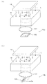
図1はこの発明にかかる撮像装置の第1実施形態の概略構成を示す図である。この撮像装置1は、複数の、例えば96個(12×8のマトリクス配列)のウェルWを形成されたサンプル(マイクロプレート)Mの下面周縁部に当接して該マイクロプレートMを略水平状態に保持するホルダ11と、該ホルダ11の上部に設けられた照明部12と、ホルダ11の下部に設けられた撮像ユニット13と、これらを司って所定の動作を実行させる制御部10とを備えている。以下の説明のために図1に示す通りに座標軸を設定する。X−Y平面は水平面であり、Z軸は鉛直軸である。
FIG. 1 is a diagram showing a schematic configuration of a first embodiment of an imaging apparatus according to the present invention. The
マイクロプレートMにおける各ウェルWの直径および深さは代表的には数mm程度であり、ウェルWそれぞれには、例えば培養液、培地、試薬などの液体等(一部のみ図示)が注入されている。なお、この撮像装置1が対象とするマイクロプレートのウェル数およびそのサイズはこれらに限定されるものではなく任意である。
The diameter and depth of each well W in the microplate M is typically about several millimeters, and each well W is injected with a liquid such as a culture solution, a medium, a reagent, or the like (only a part is shown). Yes. The number of wells and the size of the microplate targeted by the
照明部12は、制御部10に設けられた光源制御部112aによって制御され、光源制御部112aからの制御指令に応じてホルダ11に保持されたマイクロプレートMに向けて上方から光を照射する光源12aを備えている。光源12aは、ホルダ11に保持されるマイクロプレートMの平面サイズと同等もしくはそれより大きな平面サイズを有し、その下面から略一様な光量分布の光を出射する面光源である。光源12aから出射される光は可視光であり、特に白色光が好ましい。このような光源としては、蛍光によるもの、EL(Electroluminescence)によるもの、多数のLED素子をマトリクス配列したものなどを用いることができる。
The
光源12aの下面には、例えば液晶シャッターからなる透過光量調整部12bが配置されており、光源12aからマイクロプレートMに向けて照射される光の光量分布を制御する。より具体的には、透過光量調整部12bは、一方主面側から入射されて他方主面側へ透過する光の光路を微小なセル単位で開閉することにより、一方主面側から他方主面側への光の透過量を加減する。シャッターの開閉は制御部10に設けられたシャッター制御部112bによりセルごとに制御される。これにより、例えば、単位面積中シャッターが開かれた面積が大きいほど、当該領域では光の透過量が多くなる。このように、位置ごとに光の透過量を制御することで、マイクロプレートMに入射する光の光量分布を細かく制御することができる。
On the lower surface of the
なお、上記のように面光源と液晶シャッターとからなる照明部12としては、例えば既に製品化されている液晶表示パネルを用いることが可能である。すなわち、液晶表示パネルに設けられたバックライトを光源12aとして、また駆動回路を含む液晶部を透過光量調整部12bとして機能させることができる。そして、表示パネルに図形パターンを表示させるのと同様にして、種々のパターンの透過光量分布を実現することができる。さらに、カラー表示可能な表示パネルを用いれば、RGBそれぞれの波長成分に対する透過パターンを独立して設定することが可能である。撮像素子の解像度が高く、各色画素間の色分布が目立つ場合には、上記表示パネルに適宜拡散板を組み合わせて光の散乱度を上げるようにしてもよい。また面光源としては、液晶のようなシャッタータイプだけではなく、有機ELパネルのような面発光タイプのものであってもよい。
In addition, as the
上記のように構成された照明部12により、マイクロプレートMに形成された複数のウェルWに対し一括して、光量分布が制御された光Lが照明光として照射される。なお、ホルダ11へのマイクロプレートMの載置およびホルダ11からのマイクロプレートMの取り出しを容易とするために、ホルダ11の上部から照明部12を退避させることが可能な構成とすることが望ましい。このためには、照明部12を可動アームやヒンジ(図示せず)等の可動部材によって支持することが望ましい。
The
撮像ユニット13は、照明部12から出射されてホルダ11に保持されたマイクロプレートMの下方に透過してくる透過光Ltを受光することでマイクロプレートMの画像を撮像するカメラとして機能するものである。撮像の解像度としては、例えば2400dpi(dots per inch)程度とする。撮像ユニット13は制御部10に設けられたカメラ駆動機構113に連結されており、カメラ駆動機構113は、ホルダ11に保持されたマイクロプレートMの下面に沿って撮像ユニット13を水平面内で走査移動させる。すなわち、この実施形態では、撮像ユニット13がマイクロプレートMの下面に沿って走査移動可能となっている。
The
撮像ユニット13により撮像された画像データは画像処理部114に与えられる。画像処理部114は、撮像ユニット13からの画像データに対して適宜画像処理を施したり、画像データに基づく所定の演算処理を実行する。処理前後のデータは必要に応じて記憶部115に記憶保存される。また、検出処理部116は、画像処理部114から与えられる画像データに基づき所定の検出処理を行って、画像に含まれる特徴的な部位を検出する。この検出処理は、例えば画像の輝度データを解析することによって当該画像の中で光学的特性がその周囲領域とは異なる領域を検出する処理であり、また当該領域について特徴量を算出することにより、当該領域がどのような起源・種類のものであるかの分類が可能である。このように画像からある特徴を有する部位を識別し検出する処理や、そのような処理に好適な特徴量については種々の技術が公知であるので、ここでは詳しい説明を省略する。
Image data picked up by the
検出処理部116による検出結果も記憶部115に保存される。また、画像処理部114は必要に応じて検出処理部116による検出結果に基づいた画像処理を行う。そして、適宜の画像処理が施された画像データは例えば液晶ディスプレイ等の表示手段を有する表示部118に与えられ、表示部118は与えられた画像データに対応する画像を表示してユーザに提示する。さらに、この撮像装置1は、画像処理の内容や表示の態様等についてユーザからの操作指示入力を受け付けるための入力受付部117を有している。入力受付部117は、例えばキーボード、マウス、タッチパッド等の入力受付手段またはそれらを適宜組み合わせたものであり、ユーザからの指示入力を受け付けて制御部10がこれを装置の動作に反映させることで、ユーザが所望する機能を実現する。
The detection result by the
この撮像装置1は、各ウェルWに保持された流動体(本明細書では、液体、ゲル状のまたは半流動性を有する固体、および、例えば軟寒天のように流動性を有する状態でウェルに注入されその後固化するものの総称である)およびその中に含まれる細胞等の撮像対象物の光学像を撮像したり、その光学像から所定の光学的特徴を有する、より具体的にはウェルWに保持された液体等とは異なる光学的特性を有する特異な部分をその光学的特性の差異を利用して検出するという用途に適用することができる。例えば、培養液や培地中の細胞や細胞集塊(スフェロイド)を撮像対象物として撮像したり、さらに画像処理によりそのような細胞等を自動的に検出する目的に好適に使用することができる。
The
図2はマイクロプレートの構造をより詳細に示す図である。図2(a)に示すように、マイクロプレートMは、略円筒状(より厳密には、底面に向けて断面積が漸減するテーパー付き)の側面形状を有する貫通孔M1が一定のピッチで規則的に二次元マトリクス配置された上部プレートM2と、上部プレートM2の下面に各貫通孔M1を塞ぐように貼付された下面シートM3とを有している。 FIG. 2 is a diagram showing the structure of the microplate in more detail. As shown in FIG. 2 (a), the microplate M has through-holes M1 having a substantially cylindrical side surface (more precisely, tapered with a cross-sectional area gradually decreasing toward the bottom surface) with regular pitches. The upper plate M2 is arranged in a two-dimensional matrix, and the lower sheet M3 is attached to the lower surface of the upper plate M2 so as to close each through hole M1.
下面シートM3は上部プレートM2の下面にぴったりと密着されており、上部プレートM2の貫通孔M1の側面と、下面シートM3とによって囲まれた空間に液体を保持することが可能となっている。すなわち、この空間が流動体を保持するウェルWとして機能し、貫通孔M1の側面がウェルWの側壁面を、また下面シートM3がウェルWの底面をそれぞれなしている。下面シートM3は透明な樹脂、例えばPET(ポリエチレンテレフタレート)樹脂により形成されたシート体である。 The lower surface sheet M3 is closely attached to the lower surface of the upper plate M2, and the liquid can be held in a space surrounded by the side surface of the through hole M1 of the upper plate M2 and the lower surface sheet M3. That is, this space functions as a well W for holding a fluid, and the side surface of the through hole M1 forms the side wall surface of the well W, and the lower surface sheet M3 forms the bottom surface of the well W. The lower surface sheet M3 is a sheet formed of a transparent resin, for example, a PET (polyethylene terephthalate) resin.
上記のように構成されたマイクロプレートMのウェルWに流動体(例えば液体)が注入された状態で、上方から光が入射された場合を考える。このとき、図2(b)に示すように、注入された流動体の表面(液面)Sがメニスカスを形成している。この状態で上方からウェルWに均一な面内分布を有する光Lが入射されると、液面Sがほぼ水平なウェルWの中心付近では入射光Lがほぼ直進して流動体内に入射する。これに対して、ウェルWの側壁面に近い液面に入射した光は、液面での屈折により進行方向が曲げられる。これに起因して、ウェル底面のうち側壁面に近い周縁部Pでは照明光が届きにくく、図2(b)の下部に示すように、中央付近に比べて入射する光量が小さくなる傾向にある。 Consider a case where light is incident from above in a state where a fluid (for example, a liquid) is injected into the well W of the microplate M configured as described above. At this time, as shown in FIG. 2B, the surface (liquid level) S of the injected fluid forms a meniscus. When light L having a uniform in-plane distribution is incident on the well W from above in this state, the incident light L travels substantially straight and enters the fluid near the center of the well W where the liquid level S is substantially horizontal. On the other hand, the traveling direction of the light incident on the liquid surface near the side wall surface of the well W is bent due to refraction at the liquid surface. Due to this, the illumination light is difficult to reach at the peripheral edge P near the side wall surface of the well bottom surface, and as shown in the lower part of FIG. .
このような入射光量の分布は、例えばウェル底面で培養された細胞等のオブジェクトに入射する照明光の光量が位置ごとに異なることを意味する。このため、同じオブジェクトの像であってもウェルW内での位置によってその輝度が異なることになる。このことは、撮像されたオブジェクトの輝度を有意な情報として該オブジェクトを分析する処理において誤差の原因となり得る。 Such a distribution of the amount of incident light means that, for example, the amount of illumination light incident on an object such as a cell cultured on the bottom of the well varies from position to position. For this reason, even if the images of the same object, the luminance varies depending on the position in the well W. This can cause an error in the process of analyzing the object with the brightness of the imaged object as significant information.
そこで、この実施形態では、前記したように照射光量分布を制御可能な照明部12を設けている。そして、後述する撮像動作においては、撮像対象である試料を予め撮像した事前撮像画像における輝度分布に基づいて、ウェル底面に均一な光が入射するように撮像時の照明光の光量分布を設定し、該照明条件下で撮像を行う。
Therefore, in this embodiment, as described above, the
なお、ウェルWに注入された流動体の表面状態は、流動体の粘度、ウェル壁面に対する濡れ性、注入時の作業ばらつき等により試料ごとに異なる。これに起因して、ウェル底面における入射光量の分布も試料ごとに異なったものとなり得る。本実施形態の技術思想はこのように試料ごとに異なる液面の状態に対応することが可能なものであるが、ここでは理解を容易にするために、図2(b)に示すように液面が下に凸のメニスカスを形成しているものとする。 The surface state of the fluid injected into the well W varies from sample to sample due to the viscosity of the fluid, the wettability with respect to the well wall surface, the work variation during injection, and the like. Due to this, the distribution of the incident light quantity on the bottom surface of the well can be different for each sample. The technical idea of the present embodiment can cope with the different liquid level states for each sample as described above, but here, in order to facilitate understanding, as shown in FIG. It is assumed that a meniscus whose surface is convex downward is formed.
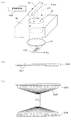
図3は本実施形態の装置が採り得る2つの撮像態様を示す図である。ここでは1つのウェルWについて撮像を行う場合の例を挙げるが、複数のウェルについて一括して撮像を行う場合でも考え方は同じである。図3(a)に示す第1の態様では、撮像対象であるウェルWの上方から、照明部12からの略均一な照明光Lが入射する。ウェルWの下方には結像光学系131と、多数の微細な受光素子を二次元配列した二次元撮像素子132が順に配置されている。これらは撮像ユニット13を構成するものであるが、図3(a)では、当該構成の撮像ユニットを他と区別するため符号13aを付している。二次元撮像素子132としては、CCDセンサおよびCMOSセンサなどを用いることができる。なお、ここでは結像光学系131を単一のレンズにより示しているが、複数のレンズからなるものであってもよい。
FIG. 3 is a diagram showing two imaging modes that the apparatus of the present embodiment can take. Here, an example in which imaging is performed for one well W will be described, but the concept is the same even when imaging is performed for a plurality of wells at once. In the first mode shown in FIG. 3A, the substantially uniform illumination light L from the
ウェルWの底面からの透過光は結像光学系131により、その下方に配置された二次元撮像素子132の受光面に収束される。これにより、二次元撮像素子132の受光面にはウェル底面およびその近傍に分布するオブジェクト(細胞等)の像が結像し、二次元撮像素子132により、ウェルの画像が取得される。この態様は、二次元パターンの照明部と二次元パターンの撮像素子との組み合わせであると言える。
The transmitted light from the bottom surface of the well W is converged by the imaging
一方、図3(b)に示す第2の態様の撮像ユニット13bでは、結像光学系131の下方に、多数の微細な受光素子を一次元配列した一次元撮像素子(ラインセンサ)133が配置される。そして、一次元撮像素子133がその長手方向(受光素子配列方向)に直交する方向Dsに走査移動しながら撮像を行うことで、上記第1の態様と同様に、ウェルWの二次元画像が取得される。この態様は、二次元パターンの照明部と一次元パターンの撮像素子との組み合わせである。撮像ユニット13が上記したいずれの態様の構成を有するものであっても、以下に説明する撮像動作を適用することが可能であり、それにより得られる作用効果は基本的に同じである。
On the other hand, in the
図4は第1実施形態における撮像動作を示すフローチャートである。ウェルWに試料を保持するマイクロプレートMがオペレータによってホルダ11にセットされた後、制御部10が装置各部を制御して図4の動作を実行することにより、試料を含むウェルWの画像が取得される。まず、透過光量調整部12bの液晶シャッターを全開状態、すなわち面内全ての位置で光源12aからの光を通過させる状態に設定する(ステップS101)。これにより、ウェルWに保持された試料の表面には、光源12aから出射される略一様な光がそのまま入射する。このときの光量分布を、後の動作の基準となる標準状態とする。
FIG. 4 is a flowchart showing the imaging operation in the first embodiment. After the microplate M holding the sample in the well W is set in the
この状態で、撮像ユニット13による撮像動作(プリスキャン動作)を実行する(ステップS102)。以下では、このときに得られた画像を「事前撮像画像」と称する。事前撮像画像では、試料表面での照明光の屈折に起因する輝度のムラが生じており、このままで各種の分析に供するには必ずしも適さないものである。この実施形態では、後の本スキャン動作における照明条件を最適化するためのサンプルとして事前撮像画像を利用する。
In this state, an imaging operation (pre-scan operation) by the
続いて、事前撮像画像に対し画像の平滑化を行う(ステップS103)。すなわち、画像に含まれる比較的高い空間周波数成分を適宜のフィルタ処理等によって除去する。事前撮像画像には試料内の細胞等の像が含まれるが、この時点で必要なのは照明光に起因する輝度の分布に関する情報であり、細胞等に関する情報は不要である。想定される細胞等のサイズに対応した平滑化を行うことにより、画像から細胞等の像を除去したバックグラウンド画像が得られる。 Subsequently, the pre-captured image is smoothed (step S103). That is, a relatively high spatial frequency component included in the image is removed by appropriate filter processing or the like. The pre-captured image includes an image of a cell or the like in the sample, but what is needed at this point is information on the luminance distribution caused by the illumination light, and information on the cell and the like is unnecessary. By performing smoothing corresponding to the assumed size of cells and the like, a background image obtained by removing the image of cells and the like from the image can be obtained.
こうして得られたバックグラウンド画像における輝度を画素ごとに求めて、該画像における輝度分布を検出する(ステップS104)。ここで検出された輝度分布は、ウェル底面への入射光量の分布を示すものである。次に、実際の撮像において均一な入射光量分布が得られるように、こうして検出された輝度分布をキャンセルするような照射光量の分布を算出する(ステップS105)。 The luminance in the background image thus obtained is obtained for each pixel, and the luminance distribution in the image is detected (step S104). The luminance distribution detected here indicates the distribution of the amount of light incident on the bottom of the well. Next, in order to obtain a uniform incident light amount distribution in actual imaging, a distribution of the irradiation light amount that cancels the luminance distribution thus detected is calculated (step S105).
図5は照射光量分布の算出モデルを示す図である。試料表面が図2(b)に示すように下に凸のメニスカスを有するとき、ウェルの中央部で輝度が高く、周縁部で低くなる輝度分布が得られると想定される。これはウェル底面への入射光量を反映したものである。このとき、光源12aから出射される光自体は面内において略一様である。したがって、図5(a)に一点鎖線で示すように、輝度の高い部分に対応する試料表面への入射光量を予め低く抑えるようにすれば、ウェル底面における光量分布をより均一な状態に近付けることが可能である。このような光量分布の調整は、透過光量調整部12bにおける透過パターンを制御することにより実現可能である。
FIG. 5 is a diagram showing a calculation model of the irradiation light amount distribution. When the sample surface has a downwardly convex meniscus as shown in FIG. 2B, it is assumed that a luminance distribution is obtained in which the luminance is high at the central portion of the well and low at the peripheral portion. This reflects the amount of light incident on the bottom of the well. At this time, the light itself emitted from the
上記のような照射光量分布の調整を行うことで、光源12aからの出射光自体に多少の光量分布(シェーディング)があったとしても、これをキャンセルすることができる。同様に、試料表面の凹凸に起因する輝度のムラについても併せてキャンセルすることが可能である。
By adjusting the irradiation light amount distribution as described above, even if there is a slight light amount distribution (shading) in the emitted light itself from the
なお、上記原理によれば光量分布は均一に近づくが、全体としての光量は低下して画像が暗くなる。均一な明るさが確保できていれば、画像全体が暗くなること自体はあまり問題とはならないと考えられる。また細胞種によっては強い光の刺激によって細胞自体の状態が変化してしまう場合がある。したがって、このように明るい部分の入射光量を低下させるという調整方法で、実用的には十分であると考えられる。一方、より明るさを必要とする用途に対しては、図5(a)に二点鎖線で示すように、光源12aからの発光量を増大させるための措置を必要に応じて実行するようにしてもよい。
According to the above principle, the light quantity distribution approaches uniform, but the overall light quantity decreases and the image becomes dark. If uniform brightness can be ensured, the darkness of the entire image itself is not considered to be a problem. Depending on the cell type, the state of the cell itself may change due to strong light stimulation. Therefore, it can be considered that the adjustment method of reducing the amount of incident light in such a bright portion is practically sufficient. On the other hand, for applications that require more brightness, measures to increase the amount of light emitted from the
図5(b)は照明光の光路上の各位置における光量分布を模式的に示している。光源12aから出射される光L1の光量は、右上の吹き出しボックス内に示したように一様(実線)または何らかの分布(破線)を有するものである。一方、事前撮像画像から設定された透過光量調整部12bにおける光の透過率は、左上の吹き出しボックス内に示したように、事前撮像画像における輝度分布を反転させたような分布となる。
FIG. 5B schematically shows the light amount distribution at each position on the optical path of the illumination light. The amount of light L1 emitted from the
その結果、透過光量調整部12bを通過した光L2の光量分布は、右中段の吹き出しボックス内に示したように、事前撮像画像において低輝度であった領域ほど光量が大きくなる。このような光L2がウェルW内の試料に入射すると、ウェル底面に入射する光L3の光量は、右下の吹き出しボックス内に示すように、位置によらずほぼ一様なものとなる。
As a result, the light amount distribution of the light L2 that has passed through the transmitted light
このように、事前撮像画像における輝度分布に基づいて透過光量調整部12bを制御し、ウェルWに入射する照明光の光量分布を調節することによって、ウェル底面に入射する光の光量分布を適切に設定することが可能である。すなわち、ウェル底面において光量分布が一様となるための試料表面における光量分布を算出し、それを実現するための透過光量調整部12bの透過パターンを求めればよい。
In this way, by controlling the transmitted light
図4に戻って撮像動作の説明を続ける。上記原理に基づき透過光量調整部12bの液晶シャッターの各セルを制御することにより、ウェル底面に入射する光の光量分布を均一化する(ステップS106)。そして、この状態で撮像ユニット13による撮像(本スキャン動作)を実行することで、細胞等のオブジェクトを含むウェルWの画像を取得することができる(ステップS107)。
Returning to FIG. 4, the description of the imaging operation will be continued. By controlling each cell of the liquid crystal shutter of the transmitted light
このように構成された撮像動作では、ウェル底面に分布するオブジェクトに略均一な光が照射された状態で撮像を行うことにより、試料表面での照明光の屈折に起因して生じる輝度ムラのない画像を取得することができる。こうして取得された画像を各種の分析に供するための出力画像とすることにより、この実施形態では、照明光に起因する輝度ムラの少ない品質の良好な画像をユーザに提供することが可能である。 In the imaging operation configured as described above, imaging is performed in a state in which substantially uniform light is irradiated on the object distributed on the bottom surface of the well, so that there is no luminance unevenness caused by refraction of illumination light on the sample surface. Images can be acquired. By using the image thus obtained as an output image for use in various types of analysis, in this embodiment, it is possible to provide a user with a good quality image with little luminance unevenness caused by illumination light.
なお、複数のウェルWについて撮像を行うに際しては、各ウェルごとに照射光量分布の設定を行うことが望ましい。この場合、1つのウェルを選択して図4に示す一連の処理を実行し、それが完了してから対象とするウェルを新たに選択して上記処理を繰り返すようにしてもよい。あるいは、複数のウェルを撮像視野に収めて一括してプリスキャン動作を行い、それぞれのウェルについてバックグラウンド画像の輝度分布を求めて照射光量分布を設定した上で本スキャン動作を行うようにしてもよい。 When imaging a plurality of wells W, it is desirable to set the irradiation light amount distribution for each well. In this case, one well may be selected and a series of processes shown in FIG. 4 may be performed, and after completion of the process, a target well may be newly selected and the above process may be repeated. Alternatively, a plurality of wells may be stored in the imaging field of view, and a pre-scan operation may be performed at once, a luminance distribution of a background image may be obtained for each well, and an irradiation light amount distribution may be set before performing the main scan operation. Good.
次に、この発明にかかる撮像装置の第2実施形態について説明する。上記した第1実施形態の撮像装置1は、マイクロプレートMの上方に配置した照明部12は略一様な光量分布を有する面光源12aを備えたものである。これに対して、次に説明する第2実施形態の撮像装置では、発光素子を1列に並べてなる線光源を有し、これをウェルWに対して走査移動させることで、ウェルW全体に照明光を入射させるものである。この点を除く装置構成および各部の基本的な動作は第1実施形態と同一であるため、以下では同一構成には同一符号を付して説明を省略する。
Next, a second embodiment of the imaging apparatus according to the present invention will be described. In the
図6はこの発明にかかる撮像装置の第2実施形態の主要部を示す図である。図6(a)に示すように、この実施形態では、ホルダ11に保持されるマイクロプレートMの上方に、マイクロプレートMの上面に向けて光L21を出射する棒状の照明部22が設けられている。また、撮像ユニット13は、図3(b)に示した一次元撮像素子133を有するものであり、照明部22の長手方向は、一次元撮像素子133における受光素子の配列方向と平行となっている。つまり、この態様は、一次元パターンの照明部と一次元パターンの撮像素子との組み合わせである。
FIG. 6 is a diagram showing a main part of a second embodiment of the imaging apparatus according to the present invention. As shown in FIG. 6A, in this embodiment, a rod-
照明部22は、マイクロプレートMに対する一次元撮像素子133の走査移動と同期して、一次元撮像素子133と一体的にマイクロプレートMに対して方向Dsに走査移動する。すなわち、この実施形態では、ウェルWのうち一次元撮像素子133と対向する部分の撮像を行いつつ、ウェルWに対する一次元撮像素子133の相対位置が刻々と変化することにより二次元画像が取得され、照明部22からの照明光は、各時刻において一次元撮像素子133が撮像する部分に集中的に照射される。
The
照明部22としては、図6(b)に示すように、微小な発光素子(例えばLED)221を棒状のベース部材222の長手方向に多数並べた、例えばLEDアレイ、バーLED等と称されるものを用いることができる。各発光素子221は、光源制御部122により個別に点灯制御される。言い換えれば、光源制御部122は、各発光素子221の点灯タイミングや発光量を個別に制御することができる。
As shown in FIG. 6B, the
なお、照明部22に設けられた多数の発光素子221については、その1つ1つが完全に独立して点灯制御されることを必要とするものではない。すなわち、隣接するいくつかの発光素子を1つのグループとして、グループ単位で点灯制御を行うようにしてもよい。また、点灯制御の態様としては点灯のオン・オフまたは発光量を調節することができ、制御対象としては点灯および消灯のタイミング、印加電圧、間欠点灯における点灯デューティなどを用いることができる。
In addition, about the many
このように構成された照明部22では、列状に配置された発光素子221のそれぞれを個別に点灯制御することにより、発光素子221の配列方向における光量分布を任意に設定することができる。また、各発光素子221の点灯の態様を、照明部22の走査移動に同期させて変化させることで、発光素子221の配列方向と直交する走査移動方向Dsにおける光量分布を任意に変化させることができる。このように、1つの発光素子221における発光量の時間的変化と、複数の発光素子221間で発光量を相違させることとの組み合わせにより、この実施形態においても、ウェルWに入射する光量(より厳密にはその積分値)の二次元的分布を任意に設定することが可能である。
In the
また、照明部22としては、図6(c)に示すように、個別に点灯制御される多数の発光素子223と、マイクロプレートMの上方に配置され、一次元撮像素子133における受光素子の配列方向と同方向に列状に配列されてマイクロプレートMの上面に向けて光を出射する多数の投光部材224と、これらの間を光学的に1対1に接続する例えば光ファイバーからなる導光部材225とを備えるものであってもよい。このような構成によっても、上記と同様の作用効果を得られる。
In addition, as shown in FIG. 6C, the
図7は第2実施形態における撮像動作を示すフローチャートである。この実施形態の撮像動作では、まず照明部22および一次元撮像素子133を所定の初期位置(撮像する領域の一方端)に位置決めする(ステップS201)。そして、標準状態として、各発光素子221の発光量を同一値に設定する(ステップS202)。具体的には、各発光素子221に印加する駆動電圧を同一値とする。同一電圧を印加しても発光素子221ごとに発光量がばらつくことが考えられるが、第1実施形態における光源12aの光量分布と同様、これをキャンセルすることが可能であるので、ここではその差は無視するものとする。
FIG. 7 is a flowchart showing an imaging operation in the second embodiment. In the imaging operation of this embodiment, first, the
続いて、第1実施形態と同様に、プリスキャン動作による事前撮像画像の取得(ステップS203)、事前撮像画像の平滑化(ステップS204)、平滑後のバックグラウンド画像の輝度分布の検出(ステップS205)およびこれをキャンセルするための照射光量分布の算出(ステップS206)を順番に行う。こうして得られた照射光量分布に基づき、発光素子221の点灯の態様を規定する発光プロファイルを、各発光素子221ごとに(または発光素子のグループごとに)設定する(ステップS207)。
Subsequently, as in the first embodiment, acquisition of a pre-captured image by a pre-scan operation (step S203), smoothing of the pre-captured image (step S204), and detection of the luminance distribution of the smoothed background image (step S205) ) And the calculation of the irradiation light amount distribution for canceling this (step S206). Based on the irradiation light amount distribution thus obtained, a light emission profile that defines the lighting mode of the
図8は発光プロファイルの考え方を説明する図である。図8上段に示すように、照明部22を走査移動方向Dsに走査移動させることによりウェルWの上方を通過させて、事前撮像画像が撮像される。同図中段は事前撮像画像から得られた輝度分布の例を示し、実線はウェルWの中央付近の上方を通過する発光素子221aの軌跡の直下位置における輝度分布を、また破線はウェルWの周縁付近の上方を通過する発光素子221bの軌跡の直下位置における輝度分布を、それぞれ示している。
FIG. 8 is a diagram for explaining the concept of the light emission profile. As shown in the upper part of FIG. 8, the pre-captured image is captured by causing the
図8下段はこのような輝度分布をキャンセルするために必要な本スキャン動作における各発光素子の発光量と、走査移動方向Dsにおける発光素子の位置(スキャン位置)との関係(発光プロファイル)を示している。実線はウェルWの中央付近の上方を通過する発光素子221aについての発光プロファイルを、また破線はウェルWの周縁付近の上方を通過する発光素子221bについての発光プロファイルをそれぞれ示している。
The lower part of FIG. 8 shows the relationship (light emission profile) between the light emission amount of each light emitting element in the main scanning operation necessary for canceling such a luminance distribution and the position (scanning position) of the light emitting element in the scanning movement direction Ds. ing. A solid line indicates a light emission profile for the
各発光素子221を一定の発光量で発光させることを基本としつつ、事前撮像画像において輝度の上昇が見られた位置では該当する発光素子の発光量を低下させることにより、結果としてウェル底面に入射する照明光の光量分布が略一様となるようにすることができる。このように、照明部22に設けられた各発光素子221ごとに(または発光素子のグループごとに)、事前撮像画像の輝度分布に基づき発光プロファイルを作成することができる。
While making each light-emitting
図7に戻ってこの実施形態の撮像動作の説明を続ける。こうして発光素子ごとの発光プロファイルが作成されると、この発光プロファイルに基づいて各発光素子221を点灯制御して発光量を調節しながら、一次元撮像素子133による本スキャン動作を実行してウェルWの画像を取得する(ステップS208)。このとき、各発光素子221の発光量が一次元撮像素子133の走査移動に同期してリアルタイムに調節されることにより、ウェル底面に入射する光量が一定した状態で撮像を行うことができる。そのため、第1実施形態と同様に、試料表面での照明光の屈折に起因して生じる輝度ムラのない画像を取得することが可能である。
Returning to FIG. 7, the description of the imaging operation of this embodiment will be continued. When the light emission profile for each light emitting element is created in this way, the main scanning operation by the one-
図9はこの発明にかかる撮像装置の第3実施形態の主要部を示す図である。この実施形態は照明部32の構成に特徴を有しており、その他の部分については上記した第1実施形態または第2実施形態の構成を適用することができる。したがって、ここでは本実施形態の特徴部分について主に説明する。
FIG. 9 is a diagram showing a main part of a third embodiment of the imaging apparatus according to the present invention. This embodiment has a feature in the configuration of the
この実施形態の照明部32は、光を出射する光源321と、ウェルWの上方に配置されて、光源321から出射された光L31を反射させてウェルWに入射させる反射ミラー部322とを備えている。反射ミラー部322は、互いに独立して角度を調整可能な微小な反射ミラー323を多数配列したものである。複数の反射ミラー323のそれぞれは、制御部10に設けられたミラー制御部332により角度制御される。このような反射ミラー部322としては、例えば表示装置に用いられるDMD(Digital Mirror Device)を使用することができる。また、光源321および反射ミラー部322としては、第1実施形態のような二次元(面光源)タイプのもの、第2実施形態のような一次元(線光源)タイプのもののいずれも使用可能である。一次元タイプでは、第2実施形態と同様に、少なくとも反射ミラー部322の撮像素子の走査移動に同期した走査移動が必要となる。
The
このような構成では、光源321から入射される光の反射方向を反射ミラー部322によって位置ごとに変化させることで、ウェルWに入射する光L32の光量分布を制御し、ウェル底面における入射光量の均一化を図ることが可能である。
In such a configuration, the reflection direction of the light incident from the
図10はこの発明にかかる撮像装置の第4実施形態の主要部を示す図である。上記各実施形態では、本スキャン動作に先立ってプリスキャン動作を行うことで事前撮像画像を取得し、その輝度分布から照射光量分布を設定している。これに対して、第4実施形態の装置では、照明光の光量分布を、予め試料表面での屈折に起因する照射光量ムラを想定したものとして設定しておくことで、個々の撮像におけるプリスキャン動作を省略している。このような態様は、例えばウェルWに注入される流動体の粘度が低く、またその注入が自動化されているなど、試料の表面状態のばらつきが小さい場合に適している。 FIG. 10 is a diagram showing the main part of a fourth embodiment of the imaging apparatus according to the present invention. In each of the above embodiments, a pre-captured image is acquired by performing a pre-scan operation prior to the main scan operation, and an irradiation light amount distribution is set from the luminance distribution. On the other hand, in the apparatus of the fourth embodiment, the pre-scan in each imaging is performed by setting the light amount distribution of the illumination light in advance by assuming the irradiation light amount unevenness caused by refraction on the sample surface. The operation is omitted. Such an embodiment is suitable when the variation of the surface state of the sample is small, for example, the viscosity of the fluid injected into the well W is low and the injection is automated.
図10(a)に示すように、この実施形態の照明部42では、ウェルWの上方に、二次元的に略一様な光量分布を有する面光源42aが配置される。そして、面光源42aとウェルWとの間に、図10(b)に示すような濃淡パターンが形成された透過光量調整部材42bが配置される。透過光量調整部材42bは、光透過性を有するシート状または平板状の部材であり、図10(b)に示すように、ウェルWの中心に対応する部分で色が濃く、これから離れるほど色が薄くなっている。
As shown in FIG. 10A, in the
そのため、透過光量調整部材42bがウェルW上方に配置されたとき、面光源42aから出射される光L41は略一様な光量分布を有する一方、透過光量調整部材42bを通過してウェルWに入射する光L42では、ウェルWの中央部で光量が少なく、周縁部ほど光量が多くなるような光量分布が与えられる。これにより、中央部に比べて入射光が届きにくい周縁部における入射光量を増大させ、ウェル底面における光量を均一なものに近付けることができる。このとき、透過光量調整部材42bの濃淡パターンの中心をウェルWの中心と一致させやすい構成となっていることが望ましい。例えば、透過光量調整部材42bとマイクロプレートMとに位置合わせ用のマークを予め設けてもよい。また例えば、マイクロプレートMに係合してウェルW上部を覆う蓋として透過光量調整部材42bを形成することで、係合により自動的に位置合わせが行われるような構造としてもよい。
Therefore, when the transmitted light
図11は第4実施形態における透過光量調整部材の作成方法の一例を示すフローチャートである。最初に、ウェル内における照明光の光量分布を取得するための較正用試料を準備する(ステップS301)。この較正用試料は、撮像動作の対象物たる試料そのものであってもよく、また該試料と同種類、同量の流動体を別のウェルに注入することにより別途作成されたものであってもよい。こうして用意された較正用試料を用いて第1実施形態と同様に撮像を行い、事前撮像画像を取得する(ステップS302)。 FIG. 11 is a flowchart showing an example of a method for creating a transmitted light amount adjusting member in the fourth embodiment. First, a calibration sample for obtaining the light amount distribution of illumination light in the well is prepared (step S301). The calibration sample may be the sample itself that is the object of the imaging operation, or may be prepared separately by injecting the same type and amount of fluid into another well. Good. Using the calibration sample thus prepared, imaging is performed in the same manner as in the first embodiment, and a pre-captured image is acquired (step S302).
続いて、こうして得られた事前撮像画像に対して、ウェルWを横切るような複数本の線分を設定し(ステップS303)、事前撮像画像中のウェルWに対応するウェル領域のうち、設定された各線分上に位置する各画素の輝度値を画像データから算出する(ステップS304)。 Subsequently, with respect to the pre-captured image obtained in this way, a plurality of line segments that cross the well W are set (step S303), and set in the well region corresponding to the well W in the pre-captured image. The luminance value of each pixel located on each line segment is calculated from the image data (step S304).
図12は線分の設定例を示す図である。図12(a)に示すように、ここでは1つのウェルWの画像に対して4本の線分A−A’、B−B’、C−C’、D−D’を設定する。各線分は、ウェルWの中心近傍で互いに交わるように等角度間隔で設定される。したがってこの例では、隣接する線分がなす角度は45度となる。 FIG. 12 is a diagram illustrating an example of setting a line segment. As shown in FIG. 12A, four line segments A-A ′, B-B ′, C-C ′, and D-D ′ are set for the image of one well W here. Each line segment is set at equiangular intervals so as to cross each other in the vicinity of the center of the well W. Therefore, in this example, the angle formed by the adjacent line segment is 45 degrees.
1つの線分(例えば線分A−A’)上における各画素の輝度値のデータ列から求まる輝度プロファイルの一例を示すのが図12(b)である。ウェルWの底面に達する照明光の光量がその中央部分で高く周縁部で低いことに対応して、同図に示すように、ウェルWに対応するウェル領域WRの中央部分では各画素の輝度が比較的高い一方、ウェル領域WRの周縁部分では各画素の輝度が比較的低い。 FIG. 12B shows an example of a luminance profile obtained from a data string of luminance values of each pixel on one line segment (for example, line segment A-A ′). Corresponding to the fact that the amount of illumination light reaching the bottom surface of the well W is high in the central portion and low in the peripheral portion, the luminance of each pixel in the central portion of the well region WR corresponding to the well W is shown in FIG. On the other hand, the brightness of each pixel is relatively low at the peripheral portion of the well region WR.
図12(b)に示される輝度プロファイルには細かい変動やスパイク状のノイズが含まれるが、前述した通り、照明光に起因する輝度の変化はより緩やかなものであると考えられる。そこで、得られた輝度プロファイルを平滑化処理する(ステップS305)。平滑化処理としては、例えば隣接データ間での移動平均処理や、波形の上側包絡線を抽出する処理などを用いることができる。 The luminance profile shown in FIG. 12B includes fine fluctuations and spike-like noise, but as described above, it is considered that the luminance change caused by the illumination light is more gradual. Therefore, the obtained luminance profile is smoothed (step S305). As the smoothing process, for example, a moving average process between adjacent data, a process of extracting an upper envelope of a waveform, or the like can be used.
次に、こうして各線分上で求められた輝度プロファイルから、ウェルW全体の輝度分布を算出する(ステップS306)。ここでは各線分上での輝度プロファイルからの内挿計算によってウェル内各画素の輝度値を算出する方法を説明するが、第1実施形態と同様の方法によって輝度分布を求めることももちろん可能である。また、本実施形態の輝度分布算出方法を第1実施形態等に適用することも可能である。 Next, the luminance distribution of the entire well W is calculated from the luminance profile thus obtained on each line segment (step S306). Here, a method of calculating the luminance value of each pixel in the well by interpolation calculation from the luminance profile on each line segment will be described, but it is of course possible to obtain the luminance distribution by the same method as in the first embodiment. . Also, the luminance distribution calculation method of the present embodiment can be applied to the first embodiment and the like.
図13はウェル内画素の輝度値の算出原理を説明するための図である。この方法では、ウェルW内の任意の1点Qにおける輝度値を、既知の輝度プロファイルから内挿により算出する。まず、ウェルWの中心Oを原点とするXY平面を設定する。図13の例では、互いに直交する線分A−A’および線分B−B’がそれぞれX軸およびY軸と一致するように座標軸が設定されている(より正確には、座標軸と一致するようにこれらの線分が予め設定される)。 FIG. 13 is a diagram for explaining the calculation principle of the luminance value of the pixel in the well. In this method, the luminance value at an arbitrary point Q in the well W is calculated by interpolation from a known luminance profile. First, an XY plane with the center O of the well W as the origin is set. In the example of FIG. 13, the coordinate axes are set so that the line segment AA ′ and the line segment BB ′ orthogonal to each other match the X axis and the Y axis (more precisely, match the coordinate axes). These line segments are set in advance as described above).
そして、先に設定した線分のうち、輝度値を算出する点Qを挟む2つを特定する。この特定に際しては、原点Oと点Qとを結ぶ線分OQの回転角と、先に設定された各線分A−A’等の回転角とを用いることができる。具体的には、1つの軸、例えばX軸からの、原点Oを中心とした線分OQの回転角をθとしたとき、線分A−A’、B−B’、C−C’、D−D’のうち、原点Oを中心としたX軸からの回転角の値が角度θに最も近い線分およびそれに次いで近い線分が、点Qを挟む線分として特定される。図13の例では線分B−B’と線分D−D’とがこれに該当する。線分B−B’、D−D’それぞれの原点Oを中心とするX軸からの回転角をそれぞれ符号α、βにより表す。なお、点Qがいずれかの線分上の点であるケースは除外してよい。当該点Qの輝度値は上記した輝度プロファイル導出時に既に求められているからである。 Then, of the previously set line segments, two that sandwich the point Q for calculating the luminance value are specified. In this specification, the rotation angle of the line segment OQ connecting the origin O and the point Q and the rotation angle of each line segment A-A ′ set in advance can be used. Specifically, when the rotation angle of the line segment OQ about the origin O from one axis, for example, the X axis, is θ, the line segments AA ′, BB ′, CC ′, Among DD ′, the line segment whose rotation angle value from the X axis with the origin O as the center is the closest to the angle θ and the line segment closest to the line segment are specified as the line segments sandwiching the point Q. In the example of FIG. 13, the line segment B-B 'and the line segment D-D' correspond to this. The rotation angles from the X axis around the origin O of each of the line segments B-B ′ and D-D ′ are represented by symbols α and β, respectively. The case where the point Q is a point on any line segment may be excluded. This is because the luminance value of the point Q has already been obtained when the above luminance profile is derived.
次に、点Qを挟む線分B−B’、D−D’上の点でいずれも原点Oからの距離が点Qと同じである点R、Sをそれぞれ特定する。これらの点R、Sにおける輝度値は既に求められており、その値をそれぞれLr、Lsとする。照明光源およびメニスカスの影響によるウェルW内での光量変化は緩やかなものであるから、原点Oを中心とし点Q、R、Sを通る円弧上において輝度値が連続的かつ緩やかに変化するものと考えることができる。例えば、当該円弧上における輝度値が原点Oを中心とする動径の回転角に比例するものと考えれば、線分B−B’上の点Rにおける輝度値Lr、線分D−D’上の点Sにおける輝度値Lsと、線分OQも含めた各線分の回転角α、β、θの値とから、点Qにおける輝度値Lqを次のようにして求めることができる。 Next, the points R and S having the same distance from the origin O as the points Q on the line segments B-B ′ and D-D ′ sandwiching the point Q are specified. The luminance values at these points R and S have already been obtained, and the values are Lr and Ls, respectively. Since the change in the amount of light in the well W due to the influence of the illumination light source and the meniscus is gradual, the luminance value changes continuously and gently on an arc passing through the points Q, R, and S with the origin O as the center. Can think. For example, if it is considered that the luminance value on the arc is proportional to the rotation angle of the radial radius around the origin O, the luminance value Lr at the point R on the line segment BB ′ and the line DD ′. The luminance value Lq at the point Q can be obtained from the luminance value Ls at the point S and the rotation angles α, β, θ including the line segment OQ as follows.
すなわち、変数m、nについて以下の連立方程式:
θ=mα+nβ
m+n=1
を解き、求められたm、nの値を次式:
Lq=mLr+nLs
に代入する。これにより、ウェルW内の任意の点Qにおける輝度値Lqを求めることができる。ウェルW内の各位置において上記計算を行うことで、ウェルW全体における輝度分布を求めることができる。
That is, the following simultaneous equations for variables m and n:
θ = mα + nβ
m + n = 1
And the calculated values of m and n are:
Lq = mLr + nLs
Assign to. Thereby, the luminance value Lq at an arbitrary point Q in the well W can be obtained. By performing the above calculation at each position in the well W, the luminance distribution in the entire well W can be obtained.
図11に戻って、透過光量調整部材の作成方法の説明を続ける。上記のようにしてウェルW全体での輝度分布が算出されると、続いて該輝度分布をキャンセルして均一な照明条件を得るための透過光量調整部材の濃度分布を算出する。すなわち、ウェルW内の各位置について、事前撮像画像において高輝度が検出された領域には比較的高濃度のマスクパターンを配することでウェルWへの入射光量を制限する一方、低輝度のウェル領域には低濃度のマスクパターンを配してより多くの光が入射するようにすることで、ウェル内における照明光の光量分布の均一化を図ることができるようにする。 Returning to FIG. 11, the description of the method of creating the transmitted light amount adjustment member will be continued. When the luminance distribution in the entire well W is calculated as described above, the density distribution of the transmitted light amount adjusting member for subsequently canceling the luminance distribution and obtaining uniform illumination conditions is calculated. That is, for each position in the well W, a relatively high density mask pattern is arranged in a region where high luminance is detected in the pre-captured image to limit the amount of light incident on the well W, while the low luminance well By arranging a low-density mask pattern in the region so that more light is incident, the light quantity distribution of the illumination light in the well can be made uniform.
具体的には、ウェルWの各位置において求められた輝度値を適宜にスケーリングし、また必要に応じて適宜のオフセット値を加算することで、各位置に対応する画素のマスクパターンの濃度値が求められる(ステップS307)。ウェルW内の照明光の光量分布を均一化するという観点からは、濃度値の絶対値よりも位置ごとの相対的な濃度差が重要である。すなわち、画像全体の明るさを制御する目的のために、事前撮像画像から求められた各画素の濃度値に適宜のオフセット値を加えてもよい。 Specifically, by appropriately scaling the luminance value obtained at each position of the well W and adding an appropriate offset value as necessary, the density value of the mask pattern of the pixel corresponding to each position can be obtained. It is obtained (step S307). From the viewpoint of uniformizing the light quantity distribution of the illumination light in the well W, the relative density difference for each position is more important than the absolute value of the density value. That is, for the purpose of controlling the brightness of the entire image, an appropriate offset value may be added to the density value of each pixel obtained from the pre-captured image.
そして、こうして求められた各画素ごとの濃度値に応じた濃度を有する濃淡パターンを透明シート上に作成することで(ステップS308)、例えば図10(b)に示すような透過光量調整部材42bが作成される。濃淡パターンの作成は、例えばインクジェット印刷によって行うことが可能である。なお、ウェルWと試料の流動性との組み合わせに起因してウェルWごとに特性が異なり、個々に補正用の濃淡パターンを用意することが煩雑となる場合がある。このような場合には、輝度分布が類似する複数のケースをグルーピングし、該グループ内で統計的に算出した輝度分布に基づく濃淡パターンを求めてこれをグループ内で共通使用するようにしてもよい。
Then, by creating a shading pattern having a density corresponding to the density value for each pixel thus obtained on the transparent sheet (step S308), for example, a transmitted light
図14はこの発明にかかる撮像装置の第5および第6実施形態の主要部を示す図である。図14(a)に示す第5実施形態においては、光源52aおよび透過光量調整部52bを有する照明部52からの照射光L51が全反射ミラー520によって反射され、その反射光L52がウェルWに入射する。このような構成は、光路を除けば実質的に第1実施形態のものと同じであり、第1実施形態と同様の効果を得ることが可能である。
FIG. 14 is a diagram showing a main part of fifth and sixth embodiments of the imaging apparatus according to the present invention. In the fifth embodiment shown in FIG. 14A, the irradiation light L51 from the
また、図14(b)に示す第6実施形態は、上記各実施形態のようにウェルWの下方に撮像ユニット13を配置するのに代えて、ウェルWの上方に撮像ユニット613を配置したものである。より具体的には、ウェルWの上方にハーフミラー620を設け、その上方に撮像ユニット613を設けている。そして、光源62aおよび透過光量調整部62bを有する照明部62からの照射光L61をハーフミラー620に入射させ、その反射光L62をウェルWに入射させる。一方、ウェルWから上方に出射される光L63についてはハーフミラー620を透過させて撮像ユニット613に入射させる。このようにした場合でも、上記各実施形態と同様に、ウェルW内のオブジェクトに略均一な光を照射して、輝度ムラの少ない画像を得ることが可能である。なお、照明部62、ハーフミラー620および撮像ユニット613をマイクロプレートMの下方に配置しても撮像は可能である。
In addition, in the sixth embodiment shown in FIG. 14B, instead of arranging the
以上説明したように、これらの実施形態においては、マイクロプレートMが本発明の「試料保持プレート」に相当しており、ウェルWが本発明の「窪部」に相当している。そして、ホルダ11が本発明の「保持手段」として機能する一方、撮像ユニット13が本発明の「撮像手段」として機能している。また、第1および第2実施形態における一次元撮像素子133が、本発明の「ラインセンサ」に相当している。また、各実施形態における照明部12、22、32、42、52および62が本発明の「光照射手段」として機能している。また、第2実施形態における発光素子221、またこれをグループ化した場合はその各グループが本発明の「発光モジュール」に相当している。
As described above, in these embodiments, the microplate M corresponds to the “sample holding plate” of the present invention, and the well W corresponds to the “concave portion” of the present invention. The
また、上記第1ないし第3実施形態においては制御部10、より詳しくは第1実施形態におけるシャッター制御部112b、第2実施形態における光源制御部122および第3実施形態におけるミラー制御部332が本発明の「制御手段」として機能しており、第4実施形態においては透過光量調整部材42bが本発明の「制御手段」として機能している。
In the first to third embodiments, the
また、図4のフローチャートにおけるステップS101およびS102が本発明の「事前撮像工程」に相当する一方、ステップS103およびS104が本発明の「輝度分布検出工程」に相当している。また、ステップS105およびS106が本発明の「光量分布設定工程」に相当し、ステップS107が本発明の「画像取得工程」に相当している。 Further, steps S101 and S102 in the flowchart of FIG. 4 correspond to the “preliminary imaging process” of the present invention, while steps S103 and S104 correspond to the “luminance distribution detection process” of the present invention. Steps S105 and S106 correspond to the “light quantity distribution setting step” of the present invention, and step S107 corresponds to the “image acquisition step” of the present invention.
なお、本発明は上記した実施形態に限定されるものではなく、その趣旨を逸脱しない限りにおいて上述したもの以外に種々の変更を行うことが可能である。例えば、上記第1実施形態では面光源と液晶シャッターとの組み合わせにより任意の二次元光量分布を得られるようにしているが、第2実施形態にその思想を示したように、多数の発光素子を二次元的に配列した光源を用いて各発光素子を個別に点灯制御することによっても、同様に光量分布を任意に設定することが可能である。 The present invention is not limited to the above-described embodiment, and various modifications other than those described above can be made without departing from the spirit of the present invention. For example, in the first embodiment, an arbitrary two-dimensional light amount distribution can be obtained by a combination of a surface light source and a liquid crystal shutter. However, as shown in the second embodiment, a large number of light emitting elements are used. Similarly, the light quantity distribution can be arbitrarily set by controlling lighting of each light emitting element individually using light sources arranged two-dimensionally.
逆に、第2実施形態においても、光量分布の固定された光源と液晶シャッター等の透過光量調整部との組み合わせによって任意の光量分布を創出するようにすることが可能である。 Conversely, also in the second embodiment, it is possible to create an arbitrary light amount distribution by a combination of a light source having a fixed light amount distribution and a transmitted light amount adjusting unit such as a liquid crystal shutter.
また、上記第1実施形態では、面光源と液晶シャッターとが一体化された液晶表示パネルを照明部として用いているが、光源と透過光量調整部とは別体に構成されたものであってもよい。また、光源と透過光量調整部との間に、光量分布を均一化させるための拡散板等をさらに備えてもよい。 Moreover, in the said 1st Embodiment, although the liquid crystal display panel with which the surface light source and the liquid-crystal shutter were integrated is used as an illumination part, a light source and a transmitted light amount adjustment part are comprised separately, and it is comprised. Also good. Further, a diffusing plate or the like for making the light amount distribution uniform may be further provided between the light source and the transmitted light amount adjusting unit.
また上記実施形態の説明においては特に言及していないが、事前撮像画像を取得するためのプリスキャン動作では、照明光の光量分布が反映されたバックグラウンド画像が得られれば足りる。この意味において必要な解像度は本スキャン動作におけるものよりもかなり低くてもよい。したがって、プリスキャン動作では撮像素子の走査速度を高くして処理時間の短縮を図る一方、本スキャン動作ではより低速で撮像素子を走査することで解像度の高い画像を取得する、というように、走査速度を切り換えて実行してもよい。また、プリスキャン動作とその結果に基づく光量分布の調整を複数回繰り返すことで、より均一な照明条件を求めるようにしてもよい。 Further, although not particularly mentioned in the description of the above-described embodiment, it is only necessary to obtain a background image in which the light amount distribution of illumination light is reflected in the pre-scan operation for acquiring a pre-captured image. In this sense, the required resolution may be considerably lower than that in the main scanning operation. Therefore, in the pre-scan operation, the scanning speed of the image sensor is increased to shorten the processing time, while in the main scan operation, a high-resolution image is acquired by scanning the image sensor at a lower speed. It may be executed by switching the speed. Further, more uniform illumination conditions may be obtained by repeating the pre-scan operation and the adjustment of the light amount distribution based on the result a plurality of times.
同じ考え方から、プリスキャン動作では複数のウェルを一括して撮像する一方、本スキャン動作では1つ1つのウェルを個別に撮像する、というように、撮像対象領域を切り換えて実行するようにしてもよい。 Based on the same idea, the pre-scan operation may be performed by switching the imaging target area, such as imaging a plurality of wells at once while the main scan operation imaging each well individually. Good.
また、本発明の透過光量調整部としてカラー液晶表示パネルを用いた場合、色ごとに透過パターンを変えることで、次のような使い方が可能である。例えば、分析の対象とする細胞の色彩に合わせて照明光の色を変えることにより、特定種の細胞のコントラストを強調した画像を取得することができる。 Further, when a color liquid crystal display panel is used as the transmitted light amount adjustment unit of the present invention, the following usage is possible by changing the transmission pattern for each color. For example, by changing the color of the illumination light in accordance with the color of the cell to be analyzed, an image in which the contrast of a specific type of cell is enhanced can be acquired.
また、上記第4実施形態における透過光量調整部材として、第1実施形態として示したような液晶シャッターを用いてもよい。また第2実施形態に示したように、光源からの出射光量自体に変化を付けることで所定の光量分布を創出するようにしてもよい。 In addition, as the transmitted light amount adjusting member in the fourth embodiment, a liquid crystal shutter as shown in the first embodiment may be used. Further, as shown in the second embodiment, a predetermined light amount distribution may be created by changing the amount of light emitted from the light source.
また、上記各実施形態の撮像装置は、撮像された画像に対して種々の画像処理による解析を実行可能な装置であるが、単に撮像のみを行う装置に対しても、本発明を適用することが可能である。 In addition, the imaging device of each of the above embodiments is a device that can perform analysis by various image processing on the captured image, but the present invention is also applied to a device that simply performs imaging. Is possible.
また、上記各実施形態では、ウェルWに入射する光の光量分布を管理することで、ウェルW内に分布するオブジェクトに均一な照明光が当たるようにしている。一方、撮像された画像において輝度ムラを生じさせない、という観点からは、次に説明するように、ウェルWから出射された光が撮像ユニットに入射するまでの光路上において光量分布の調整を行うことも可能である。 Further, in each of the above-described embodiments, by managing the light amount distribution of light incident on the well W, uniform illumination light strikes the objects distributed in the well W. On the other hand, from the viewpoint of not causing luminance unevenness in the captured image, the light amount distribution is adjusted on the optical path until the light emitted from the well W enters the imaging unit, as described below. Is also possible.
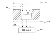
図15はウェルと撮像ユニットとの間で光量分布を調整する例を示す図である。この例では、ウェルWを有するマイクロプレートMの上方に適宜の面内光量分布を有する照明部72を設け、ウェルWの上方から照明光L71を入射させる。ウェルWの底面の直下には、上記各実施形態で用いたのと同様の透過光量調整部720が配置され、その下方に撮像ユニット713が設けられる。このような構成では、たとえウェルWから出射される光が照明光の不均一さに起因する光量分布を有していたとしても、透過光量調整部720を通過して撮像ユニット713に入射する光L72ではその不均一さが解消される。これにより、撮像された画像における輝度ムラが抑制される。
FIG. 15 is a diagram illustrating an example of adjusting the light amount distribution between the well and the imaging unit. In this example, an
このように、最終的に撮像ユニット713に入射する光の光量分布を調整することにより、画像の輝度ムラを抑えることができる。光に対する感度が非線形性を有する受光素子を用いた撮像ユニットであっても、オブジェクトの背景部分の輝度をほぼ均一なレベルとしておくことにより、このような非線形性の影響の少ない画像を取得することが可能である。
As described above, by adjusting the light amount distribution of the light finally incident on the
なお、透過光量調整部材720についてはマイクロプレートMの下面に密着させてもよく、特に、第4実施形態として示した濃淡パターンが予め形成されたシート状の部材を透過光量調整部720として用いる場合には、このようなシートをマイクロプレートMの下面に貼り付けておくようにしてもよい。例えば、濃淡パターンが形成されたシートを予めマイクロプレートMと一体化させたものを用いることもできる。
Note that the transmitted light
この発明は、例えば医療・生物科学分野で用いられるマイクロプレート上のウェルのような、窪部に流動体が注入されてなる試料の観察を必要とする分野に特に好適に適用することができるが、その応用分野は医療・生物科学分野に限定されない。 The present invention can be particularly suitably applied to a field that requires observation of a sample in which a fluid is injected into a recess, such as a well on a microplate used in the medical / biological science field. The application field is not limited to the medical / biological science field.
1 撮像装置
10 制御部(制御手段)
11 ホルダ(保持手段)
13 撮像ユニット(撮像手段)
42b 透過光量調整部材(制御手段)
112b シャッター制御部(制御手段)
122 光源制御部(制御手段)
133 一次元撮像素子(ラインセンサ)
221 発光素子(発光モジュール)
332 ミラー制御部(制御手段)
M マイクロプレート(試料保持プレート)
S101,S102 事前撮像工程
S103,S104 輝度分布検出工程
S105,S106 光量分布設定工程
S107 画像取得工程
W ウェル(窪部)
DESCRIPTION OF
11 Holder (holding means)
13 Imaging unit (imaging means)
42b Transmitted light amount adjusting member (control means)
112b Shutter control unit (control means)
122 Light source control unit (control means)
133 One-dimensional image sensor (line sensor)
221 Light emitting element (light emitting module)
332 Mirror control unit (control means)
M microplate (sample holding plate)
S101, S102 Pre-imaging process S103, S104 Luminance distribution detection process S105, S106 Light intensity distribution setting process S107 Image acquisition process W well (recessed part)
Claims (16)
前記保持手段に保持された前記試料保持プレートの上方から、前記窪部に流動体が注入されてなる試料の表面に光を入射させる光照射手段と、
前記試料を撮像して前記試料の画像を取得する撮像手段と、
前記光照射手段から前記試料の表面に入射させる光の光量分布を制御する制御手段と
を備え、
前記制御手段は、予め前記光量分布を所定の標準状態に設定して前記撮像手段が前記試料を撮像した事前撮像画像から所定の空間周波数以上の高周波成分を除去したバックグラウンド画像における輝度分布に基づいて、前記試料の表面に入射させる光の光量分布を設定し、
前記撮像手段は、前記制御手段により設定された光量分布での光照射下で、前記試料の画像を取得する
ことを特徴とする撮像装置。 Holding means for holding the sample holding plate formed with a recess capable of holding liquid in a substantially horizontal state;
A light irradiating means for causing light to enter the surface of the sample formed by injecting a fluid into the recess from above the sample holding plate held by the holding means;
Imaging means for imaging the sample and obtaining an image of the sample;
Control means for controlling the light quantity distribution of light incident on the surface of the sample from the light irradiation means,
The control means sets the light quantity distribution in a predetermined standard state in advance, and based on the luminance distribution in the background image in which the imaging means removes high frequency components of a predetermined spatial frequency or higher from the pre-captured image obtained by imaging the sample. And setting the light quantity distribution of the light incident on the surface of the sample,
The imaging apparatus is characterized in that the imaging unit acquires an image of the sample under light irradiation with a light amount distribution set by the control unit.
略水平に保持した前記試料保持プレートの上方から前記試料の表面に向けて、光量分布が所定の標準状態である光を照射し、前記試料を撮像して事前撮像画像を取得する事前撮像工程と、
前記事前撮像画像から所定の空間周波数以上の高周波成分を除去したバックグラウンド画像の輝度分布を検出する輝度分布検出工程と、
前記検出工程での検出結果に基づき前記試料に入射させる光の光量分布を設定する光量分布設定工程と、
前記光量分布設定工程で設定された光量分布での光照射下で、前記試料の画像を取得する画像取得工程と
を備えることを特徴とする撮像方法。 In an imaging method for imaging a sample formed by injecting a fluid into a recess provided in a sample holding plate,
A pre-imaging step of irradiating light with a light intensity distribution in a predetermined standard state from above the sample holding plate held substantially horizontally toward the surface of the sample and capturing the sample to obtain a pre-captured image; ,
A luminance distribution detection step of detecting a luminance distribution of a background image obtained by removing high frequency components of a predetermined spatial frequency or higher from the pre-captured image;
A light amount distribution setting step for setting a light amount distribution of light incident on the sample based on the detection result in the detection step;
An image acquisition method comprising: an image acquisition step of acquiring an image of the sample under light irradiation with the light amount distribution set in the light amount distribution setting step.
Priority Applications (2)
| Application Number | Priority Date | Filing Date | Title |
|---|---|---|---|
| JP2013011736A JP5690359B2 (en) | 2012-03-30 | 2013-01-25 | Imaging apparatus and imaging method |
| US13/793,079 US9204105B2 (en) | 2012-03-30 | 2013-03-11 | Imaging apparatus and imaging method |
Applications Claiming Priority (3)
| Application Number | Priority Date | Filing Date | Title |
|---|---|---|---|
| JP2012078846 | 2012-03-30 | ||
| JP2012078846 | 2012-03-30 | ||
| JP2013011736A JP5690359B2 (en) | 2012-03-30 | 2013-01-25 | Imaging apparatus and imaging method |
Publications (3)
| Publication Number | Publication Date |
|---|---|
| JP2013228361A JP2013228361A (en) | 2013-11-07 |
| JP2013228361A5 JP2013228361A5 (en) | 2014-10-30 |
| JP5690359B2 true JP5690359B2 (en) | 2015-03-25 |
Family
ID=49234450
Family Applications (1)
| Application Number | Title | Priority Date | Filing Date |
|---|---|---|---|
| JP2013011736A Active JP5690359B2 (en) | 2012-03-30 | 2013-01-25 | Imaging apparatus and imaging method |
Country Status (2)
| Country | Link |
|---|---|
| US (1) | US9204105B2 (en) |
| JP (1) | JP5690359B2 (en) |
Families Citing this family (16)
| Publication number | Priority date | Publication date | Assignee | Title |
|---|---|---|---|---|
| EP3077796A4 (en) * | 2013-12-06 | 2017-08-23 | Bacterioscan Ltd. | Optical measurements of liquids having free surface |
| JP6301194B2 (en) * | 2014-05-26 | 2018-03-28 | 浜松ホトニクス株式会社 | Optical plate, light irradiation device, light measurement device, light irradiation method, and light measurement method |
| CN104092941A (en) * | 2014-07-10 | 2014-10-08 | 深圳市得意自动化科技有限公司 | Camera shooting method achieved through camera shooting elements |
| JP6389721B2 (en) * | 2014-09-30 | 2018-09-12 | 株式会社Screenホールディングス | Imaging apparatus and imaging method |
| JP6535494B2 (en) * | 2015-03-31 | 2019-06-26 | 株式会社Screenホールディングス | Imaging device, imaging method and culture vessel |
| JP6534294B2 (en) * | 2015-04-30 | 2019-06-26 | 富士フイルム株式会社 | Imaging apparatus and method, and imaging control program |
| CN105136684A (en) * | 2015-08-14 | 2015-12-09 | 上海蓝怡科技股份有限公司 | Multi-sample detection device and method |
| JP6577793B2 (en) * | 2015-08-28 | 2019-09-18 | 株式会社Screenホールディングス | Light regulating device and imaging method |
| JP6239562B2 (en) | 2015-09-14 | 2017-11-29 | 株式会社東芝 | LIGHTING DEVICE AND BIO INFORMATION MEASURING DEVICE INCLUDING THE SAME |
| WO2018061131A1 (en) * | 2016-09-28 | 2018-04-05 | オリンパス株式会社 | Cell status assessment device |
| KR20180046098A (en) * | 2016-10-27 | 2018-05-08 | 삼성전자주식회사 | Test Apparatus, Test System and Control Method of Test Apparatus |
| US10983325B2 (en) * | 2016-12-12 | 2021-04-20 | Molecular Devices, Llc | Trans-illumination imaging with an array of light sources |
| JPWO2019069823A1 (en) | 2017-10-03 | 2020-11-19 | 富士フイルム株式会社 | Imaging device, operation method of imaging device, and imaging control program |
| WO2020066959A1 (en) * | 2018-09-25 | 2020-04-02 | パイオニア株式会社 | Optical sample, optical member, and optical device |
| GB2581363A (en) * | 2019-02-14 | 2020-08-19 | Univ Exeter | Test apparatus |
| US11828654B2 (en) * | 2019-09-18 | 2023-11-28 | Roumiana Tsenkova | Spectroscopic analyzer and spectroscopic analysis method |
Family Cites Families (25)
| Publication number | Priority date | Publication date | Assignee | Title |
|---|---|---|---|---|
| JPH06148066A (en) | 1992-11-06 | 1994-05-27 | Suzuki Motor Corp | Optical system correcting device for particle agglomeration inspecting device |
| JPH06174635A (en) | 1992-12-08 | 1994-06-24 | Suzuki Motor Corp | Face emission source for agglomeration tester |
| US6718053B1 (en) | 1996-11-27 | 2004-04-06 | Chromavision Medical Systems, Inc. | Method and apparatus for automated image analysis of biological specimens |
| JPH1137924A (en) * | 1997-07-18 | 1999-02-12 | Hitachi Koki Co Ltd | Brightness correction method for aggregation image discriminating system |
| EP3093649B1 (en) | 1998-05-16 | 2019-05-08 | Life Technologies Corporation | A combination of a reaction apparatus and an optical instrument monitoring dna polymerase chain reactions |
| JP2002541494A (en) | 1999-04-13 | 2002-12-03 | クロマビジョン メディカル システムズ インコーポレイテッド | Histological reconstruction and automatic image analysis |
| JP2001083090A (en) * | 1999-09-10 | 2001-03-30 | Fuji Photo Film Co Ltd | Excitation light source for micro titer plate |
| AU2883702A (en) | 2000-11-03 | 2002-05-15 | Cytyc Corp | Cytological imaging systems and methods |
| US7050620B2 (en) | 2001-03-30 | 2006-05-23 | Heckman Carol A | Method of assaying shape and structural features in cells |
| US7120282B2 (en) | 2003-01-29 | 2006-10-10 | General Electric Company | Method and apparatus for correcting digital X-ray images |
| US7129473B2 (en) | 2003-05-16 | 2006-10-31 | Olympus Corporation | Optical image pickup apparatus for imaging living body tissue |
| JP4377171B2 (en) * | 2003-07-15 | 2009-12-02 | Tdk株式会社 | Spatial light modulator |
| US7283654B2 (en) | 2004-08-26 | 2007-10-16 | Lumeniq, Inc. | Dynamic contrast visualization (DCV) |
| US7718131B2 (en) | 2005-07-06 | 2010-05-18 | Genetix Limited | Methods and apparatus for imaging and processing of samples in biological sample containers |
| WO2007015438A1 (en) * | 2005-08-03 | 2007-02-08 | Olympus Corporation | Mixing device and analysis device having the mixing device |
| WO2007074929A1 (en) * | 2005-12-27 | 2007-07-05 | Olympus Corporation | Device and method for capturing image of a sample originating from organism |
| US7516934B2 (en) | 2006-02-24 | 2009-04-14 | Bio-Rad Laboratories, Inc. | Sample plate support of adjustable angular orientation |
| JP4869843B2 (en) | 2006-09-06 | 2012-02-08 | オリンパス株式会社 | Cell image processing apparatus and cell image processing method |
| JP2010503847A (en) | 2006-09-14 | 2010-02-04 | オックスフォード・ジーン・テクノロジー・アイピー・リミテッド | Device for imaging single molecules |
| US7692162B2 (en) * | 2006-12-21 | 2010-04-06 | Bio-Rad Laboratories, Inc. | Imaging of two-dimensional arrays |
| US8351683B2 (en) * | 2007-12-25 | 2013-01-08 | Hitachi High-Technologies Corporation | Inspection apparatus and inspection method |
| JP2010044004A (en) * | 2008-08-18 | 2010-02-25 | Nec Corp | Apparatus, method and program for detecting transmitted light, and method of manufacturing sheet material |
| JP5745752B2 (en) | 2009-05-21 | 2015-07-08 | オリンパス株式会社 | Cell screening method, control software used in the method, cell screening device, image analysis device, and cell screening system |
| JPWO2011048886A1 (en) * | 2009-10-20 | 2013-03-07 | オリンパスメディカルシステムズ株式会社 | Fluorescence observation equipment |
| JP5543280B2 (en) * | 2010-06-01 | 2014-07-09 | キヤノン株式会社 | Image processing apparatus and image processing method |
-
2013
- 2013-01-25 JP JP2013011736A patent/JP5690359B2/en active Active
- 2013-03-11 US US13/793,079 patent/US9204105B2/en active Active
Also Published As
| Publication number | Publication date |
|---|---|
| US20130258076A1 (en) | 2013-10-03 |
| JP2013228361A (en) | 2013-11-07 |
| US9204105B2 (en) | 2015-12-01 |
Similar Documents
| Publication | Publication Date | Title |
|---|---|---|
| JP5690359B2 (en) | Imaging apparatus and imaging method | |
| US9581797B2 (en) | High-throughput hyperspectral imaging with superior resolution and optical sectioning | |
| JP6340793B2 (en) | Optical device | |
| JP6062059B2 (en) | Bioimaging method | |
| US10522095B2 (en) | Display device | |
| CN107645625B (en) | Image generation device and image generation method | |
| CN106405914B (en) | Display device and lighting device | |
| JP5424659B2 (en) | Inspection device for inspection object | |
| US10417790B2 (en) | Shading correction apparatus and method for operating shading correction apparatus | |
| US20070064287A1 (en) | Back-light module for image scanning device and method for calibrating illumination with the back-light module | |
| EP3551054B1 (en) | Trans-illumination imaging with an array of light sources | |
| JP7021348B2 (en) | Safety light curtain that disables the rotation of the carousel | |
| JP2015535593A (en) | Container and system for optical analysis of sample without using optical lens | |
| JP7004808B2 (en) | Opposed edge system for scanning and processing glass slides | |
| JP7004813B2 (en) | Fixed reference edge system for slide loading and unloading | |
| JP2020535478A (en) | Double-pass macro image | |
| JP2013170861A (en) | Imaging apparatus, sample holding plate and imaging method | |
| JP5424660B2 (en) | Inspection device for inspection object | |
| JP2006284212A (en) | Unevenness inspection device and unevenness inspection method | |
| KR200482197Y1 (en) | Apparatus for viewing through optical thin film color filters and their overlaps | |
| US11536667B2 (en) | Image inspection apparatus and image inspection method | |
| JP2010020151A (en) | Observation apparatus | |
| JP2009156872A6 (en) | Inspection device for inspection object | |
| JP2021501349A (en) | Carousel for 2x3 and 1x3 slides | |
| JP5775550B2 (en) | Imaging apparatus and imaging method |
Legal Events
| Date | Code | Title | Description |
|---|---|---|---|
| A521 | Request for written amendment filed |
Free format text: JAPANESE INTERMEDIATE CODE: A523 Effective date: 20140916 |
|
| A621 | Written request for application examination |
Free format text: JAPANESE INTERMEDIATE CODE: A621 Effective date: 20140916 |
|
| A871 | Explanation of circumstances concerning accelerated examination |
Free format text: JAPANESE INTERMEDIATE CODE: A871 Effective date: 20140916 |
|
| A975 | Report on accelerated examination |
Free format text: JAPANESE INTERMEDIATE CODE: A971005 Effective date: 20141007 |
|
| A131 | Notification of reasons for refusal |
Free format text: JAPANESE INTERMEDIATE CODE: A131 Effective date: 20141014 |
|
| A521 | Request for written amendment filed |
Free format text: JAPANESE INTERMEDIATE CODE: A523 Effective date: 20141204 |
|
| TRDD | Decision of grant or rejection written | ||
| A01 | Written decision to grant a patent or to grant a registration (utility model) |
Free format text: JAPANESE INTERMEDIATE CODE: A01 Effective date: 20150106 |
|
| A61 | First payment of annual fees (during grant procedure) |
Free format text: JAPANESE INTERMEDIATE CODE: A61 Effective date: 20150130 |
|
| R150 | Certificate of patent or registration of utility model |
Ref document number: 5690359 Country of ref document: JP Free format text: JAPANESE INTERMEDIATE CODE: R150 |
|
| R250 | Receipt of annual fees |
Free format text: JAPANESE INTERMEDIATE CODE: R250 |
|
| R250 | Receipt of annual fees |
Free format text: JAPANESE INTERMEDIATE CODE: R250 |
|
| R250 | Receipt of annual fees |
Free format text: JAPANESE INTERMEDIATE CODE: R250 |
|
| R250 | Receipt of annual fees |
Free format text: JAPANESE INTERMEDIATE CODE: R250 |
|
| R250 | Receipt of annual fees |
Free format text: JAPANESE INTERMEDIATE CODE: R250 |
|
| R250 | Receipt of annual fees |
Free format text: JAPANESE INTERMEDIATE CODE: R250 |
|
| R250 | Receipt of annual fees |
Free format text: JAPANESE INTERMEDIATE CODE: R250 |