JP5680657B2 - Scheduled access point for peer-to-peer communication - Google Patents
Scheduled access point for peer-to-peer communication Download PDFInfo
- Publication number
- JP5680657B2 JP5680657B2 JP2012537123A JP2012537123A JP5680657B2 JP 5680657 B2 JP5680657 B2 JP 5680657B2 JP 2012537123 A JP2012537123 A JP 2012537123A JP 2012537123 A JP2012537123 A JP 2012537123A JP 5680657 B2 JP5680657 B2 JP 5680657B2
- Authority
- JP
- Japan
- Prior art keywords
- station information
- communication
- control message
- information field
- field
- Prior art date
- Legal status (The legal status is an assumption and is not a legal conclusion. Google has not performed a legal analysis and makes no representation as to the accuracy of the status listed.)
- Expired - Fee Related
Links
- 238000004891 communication Methods 0.000 title claims description 193
- 238000000034 method Methods 0.000 claims description 56
- 230000005540 biological transmission Effects 0.000 claims description 35
- 230000004044 response Effects 0.000 claims description 19
- 238000004590 computer program Methods 0.000 claims description 16
- 230000005405 multipole Effects 0.000 claims description 12
- 101100161473 Arabidopsis thaliana ABCB25 gene Proteins 0.000 description 11
- 101100096893 Mus musculus Sult2a1 gene Proteins 0.000 description 11
- 101150081243 STA1 gene Proteins 0.000 description 11
- 230000006870 function Effects 0.000 description 9
- OVGWMUWIRHGGJP-WVDJAODQSA-N (z)-7-[(1s,3r,4r,5s)-3-[(e,3r)-3-hydroxyoct-1-enyl]-6-thiabicyclo[3.1.1]heptan-4-yl]hept-5-enoic acid Chemical compound OC(=O)CCC\C=C/C[C@@H]1[C@@H](/C=C/[C@H](O)CCCCC)C[C@@H]2S[C@H]1C2 OVGWMUWIRHGGJP-WVDJAODQSA-N 0.000 description 8
- 101000988961 Escherichia coli Heat-stable enterotoxin A2 Proteins 0.000 description 8
- 238000005516 engineering process Methods 0.000 description 6
- 239000000969 carrier Substances 0.000 description 5
- 230000003287 optical effect Effects 0.000 description 4
- 238000012546 transfer Methods 0.000 description 4
- 238000013459 approach Methods 0.000 description 3
- 239000003795 chemical substances by application Substances 0.000 description 3
- 101000752249 Homo sapiens Rho guanine nucleotide exchange factor 3 Proteins 0.000 description 2
- 102100021689 Rho guanine nucleotide exchange factor 3 Human genes 0.000 description 2
- 230000001413 cellular effect Effects 0.000 description 2
- 239000000835 fiber Substances 0.000 description 2
- 230000000977 initiatory effect Effects 0.000 description 2
- 238000012545 processing Methods 0.000 description 2
- 230000003068 static effect Effects 0.000 description 2
- 238000005538 encapsulation Methods 0.000 description 1
- 239000000463 material Substances 0.000 description 1
- 230000007246 mechanism Effects 0.000 description 1
- 238000012986 modification Methods 0.000 description 1
- 230000004048 modification Effects 0.000 description 1
- 239000005022 packaging material Substances 0.000 description 1
- 230000008054 signal transmission Effects 0.000 description 1
- 238000012876 topography Methods 0.000 description 1
Images


Classifications
-
- H—ELECTRICITY
- H04—ELECTRIC COMMUNICATION TECHNIQUE
- H04W—WIRELESS COMMUNICATION NETWORKS
- H04W74/00—Wireless channel access
- H04W74/04—Scheduled access
- H04W74/06—Scheduled access using polling
-
- H—ELECTRICITY
- H04—ELECTRIC COMMUNICATION TECHNIQUE
- H04W—WIRELESS COMMUNICATION NETWORKS
- H04W52/00—Power management, e.g. TPC [Transmission Power Control], power saving or power classes
- H04W52/02—Power saving arrangements
- H04W52/0209—Power saving arrangements in terminal devices
- H04W52/0212—Power saving arrangements in terminal devices managed by the network, e.g. network or access point is master and terminal is slave
- H04W52/0222—Power saving arrangements in terminal devices managed by the network, e.g. network or access point is master and terminal is slave in packet switched networks
-
- H—ELECTRICITY
- H04—ELECTRIC COMMUNICATION TECHNIQUE
- H04W—WIRELESS COMMUNICATION NETWORKS
- H04W74/00—Wireless channel access
- H04W74/08—Non-scheduled access, e.g. ALOHA
-
- H—ELECTRICITY
- H04—ELECTRIC COMMUNICATION TECHNIQUE
- H04W—WIRELESS COMMUNICATION NETWORKS
- H04W72/00—Local resource management
- H04W72/12—Wireless traffic scheduling
-
- H—ELECTRICITY
- H04—ELECTRIC COMMUNICATION TECHNIQUE
- H04W—WIRELESS COMMUNICATION NETWORKS
- H04W72/00—Local resource management
- H04W72/20—Control channels or signalling for resource management
- H04W72/23—Control channels or signalling for resource management in the downlink direction of a wireless link, i.e. towards a terminal
-
- H—ELECTRICITY
- H04—ELECTRIC COMMUNICATION TECHNIQUE
- H04W—WIRELESS COMMUNICATION NETWORKS
- H04W74/00—Wireless channel access
- H04W74/02—Hybrid access
-
- H—ELECTRICITY
- H04—ELECTRIC COMMUNICATION TECHNIQUE
- H04W—WIRELESS COMMUNICATION NETWORKS
- H04W74/00—Wireless channel access
- H04W74/08—Non-scheduled access, e.g. ALOHA
- H04W74/0808—Non-scheduled access, e.g. ALOHA using carrier sensing, e.g. carrier sense multiple access [CSMA]
- H04W74/0816—Non-scheduled access, e.g. ALOHA using carrier sensing, e.g. carrier sense multiple access [CSMA] with collision avoidance
-
- H—ELECTRICITY
- H04—ELECTRIC COMMUNICATION TECHNIQUE
- H04W—WIRELESS COMMUNICATION NETWORKS
- H04W76/00—Connection management
- H04W76/10—Connection setup
- H04W76/14—Direct-mode setup
-
- Y—GENERAL TAGGING OF NEW TECHNOLOGICAL DEVELOPMENTS; GENERAL TAGGING OF CROSS-SECTIONAL TECHNOLOGIES SPANNING OVER SEVERAL SECTIONS OF THE IPC; TECHNICAL SUBJECTS COVERED BY FORMER USPC CROSS-REFERENCE ART COLLECTIONS [XRACs] AND DIGESTS
- Y02—TECHNOLOGIES OR APPLICATIONS FOR MITIGATION OR ADAPTATION AGAINST CLIMATE CHANGE
- Y02D—CLIMATE CHANGE MITIGATION TECHNOLOGIES IN INFORMATION AND COMMUNICATION TECHNOLOGIES [ICT], I.E. INFORMATION AND COMMUNICATION TECHNOLOGIES AIMING AT THE REDUCTION OF THEIR OWN ENERGY USE
- Y02D30/00—Reducing energy consumption in communication networks
- Y02D30/70—Reducing energy consumption in communication networks in wireless communication networks
Landscapes
- Engineering & Computer Science (AREA)
- Computer Networks & Wireless Communication (AREA)
- Signal Processing (AREA)
- Mobile Radio Communication Systems (AREA)
Description
(35U.S.C第119条の下での優先権の主張)
この特許出願は、2009年10月29日に出願され、これについて譲渡人に譲渡され、この中に参照によって明確に組み入れられた仮特許出願第61/255,993号の優先権を主張する。
(Claim of priority under 35 USC 119)
This patent application claims priority from provisional patent application 61 / 255,993, filed Oct. 29, 2009, which was assigned to the assignee and expressly incorporated herein by reference.
現在の開示のある態様は、一般的に、無線通信に、より詳細には、ピア・ツー・ピア通信のスケジューリングに関連する。 Certain aspects of the current disclosure relate generally to wireless communications, and more particularly to scheduling of peer-to-peer communications.
1つのアクセス・ポイント(access point:AP)に関連した、2つのユーザ・ステーション(STA)(たとえば、STA1とSTA2の)の間でデータを伝送させるために、一般的に2つのアプローチが利用可能である。1つのアプローチでは、STA1はAPにデータを送信することができ、そしてAPがSTA2にデータを転送することができる。もう1つのアプローチでは、STA1は、STA2と、ダイレクト・リンク・セットアップ(Direct Link Setup:DLS)接続をセット・アップする。DLSに関するメッセージは、APを通して転送される。いったんDLS接続がセット・アップされると、STA1は直接的にSTA2にデータ・パケットを送信することができる。 Two approaches are generally available for transmitting data between two user stations (STAs) (eg, STA1 and STA2) associated with one access point (AP) It is. In one approach, STA1 can send data to the AP, and the AP can transfer data to STA2. In another approach, STA1 sets up a direct link setup (DLS) connection with STA2. Messages regarding DLS are forwarded through the AP. Once the DLS connection is set up, STA1 can send data packets directly to STA2.
現在、DLSを用いて運ばれるフレームは、コンテンション・プロトコルに基づいたキャリア感知多重アクセス(Carrier Sense Multiple Access:CSMA)を用いて送信されている。しかしながら、いくつかのDLS接続があるシナリオでは、多重のDLSストリームに関するスループットを減らすことのできるかなりの衝突が起こり得る。 Currently, frames carried using DLS are transmitted using Carrier Sense Multiple Access (CSMA) based on a contention protocol. However, in scenarios where there are several DLS connections, significant collisions can occur that can reduce the throughput for multiple DLS streams.
ある態様は、無線通信に関する方法を提供する。前記の方法は、前記のスケジュールが送信する第1の装置のための時間を示し、受信する第2の装置のための同じ時間を示す、装置間の多重通信に関するスケジュールを決めることと、第1の装置と第2の装置にスケジュールを送信することを含んでいる。 Certain aspects provide a method for wireless communications. The method includes determining a schedule for multiple communications between devices, wherein the schedule indicates a time for a first device to transmit and indicates the same time for a second device to receive; Sending the schedule to the second device and the second device.
ある態様は、無線通信に関する装置を提供する。前記装置は一般的に、スケジュールが送信する第1の装置のための時間を示し、受信する第2の装置のための同じ時間を示すような、装置間の多重通信に関するスケジュールを決めるように構成される回路と、第1の装置と第2の装置にスケジュールを送信するように構成される送信機と、を含む。 Certain aspects provide an apparatus for wireless communications. The device is generally configured to determine a schedule for multiplex communication between devices such that the schedule indicates the time for the first device to transmit and the same time for the second device to receive And a transmitter configured to transmit the schedule to the first device and the second device.
ある態様は、無線通信に関する装置を提供する。前記装置は一般的に、スケジュールは、送信する第1の装置のための時間と受信する第2の装置のための同じ時間を示す、装置間の多重通信に関するスケジュールを決めるための手段と、第1の装置と第2の装置に対してスケジュールを送信するための手段と、を含んでいる。 Certain aspects provide an apparatus for wireless communications. The device generally has means for determining a schedule for multiplex communication between devices, wherein the schedule indicates a time for a first device to transmit and a same time for a second device to receive; Means for transmitting a schedule to one device and a second device.
ある態様は、無線通信に関するコンピュータ・プログラム製品を提供する。前記のコンピュータ・プログラム製品は、スケジュールが送信する第1の装置のための時間と受信する第2の装置のための同じ時間を示す、装置間の多重通信に関するスケジュールを決定することと、スケジュールを第1の装置と第2の装置に送信することを実行できる命令からなるコンピュータ可読媒体を含んでいる。 Certain aspects provide a computer program product for wireless communications. The computer program product determines a schedule for multiplex communication between devices, indicating a time for the first device that the schedule transmits and the same time for the second device that receives the schedule; A computer readable medium comprising instructions capable of being transmitted to a first device and a second device is included.
ある態様は、アクセス・ポイントを提供する。前記のアクセス・ポイントは一般的に、少なくとも1つのアンテナと、スケジュールが送信する第1の無線ノードのための時間を示し、受信する第2の無線ノードのための同じ時間を示す、無線ノード間の多重通信に関するスケジュールを決めるために構成された回路と、第1と第2の無線ノードに対して少なくとも1つのアンテナを経由してスケジュールを送信するように構成される送信機と、を含んでいる。 Certain aspects provide an access point. Said access point typically indicates at least one antenna and the time for the first radio node on which the schedule transmits and indicates the same time for the second radio node to receive between radio nodes A circuit configured to determine a schedule for multiple communications of the first and second transmitters configured to transmit the schedule to the first and second wireless nodes via at least one antenna. Yes.
ある態様は、無線通信に関する方法を提供する。前記の方法は一般的に、第1の装置で通信に関する時間を示す制御メッセージを受信することと、通信に関する同じ時間を割り当てられた第2の装置を識別することと、前記時間中に第2の装置と通信すること、を含んでいる。 Certain aspects provide a method for wireless communications. The method generally includes receiving a control message indicating a time related to communication at a first device, identifying a second device assigned the same time related to communication, and a second during the time. Communicating with other devices.
ある態様は、無線通信に関する装置を提供する。前記装置は一般的に、通信に関する時間を示す制御メッセージを受信するように構成される受信機と、通信に関する同じ時間を割り当てられたもう1方の装置を定義するために構成される回路と、前記時間中にもう1方の装置と通信するために構成されるトランシーバを含んでいる。 Certain aspects provide an apparatus for wireless communications. The device is generally configured to receive a control message indicating a time related to communication, a circuit configured to define another device assigned the same time related to communication; A transceiver configured to communicate with the other device during the time period.
ある態様は、無線通信に関する装置を提供する。前記装置は一般的に、通信に関する時間を示す制御メッセージを受信するための手段と、通信に関する同じ時間を割り当てられた他の装置と識別するための手段と、前記期間中にもう1方の装置と通信するための手段を含んでいる。 Certain aspects provide an apparatus for wireless communications. The device generally includes means for receiving a control message indicating a time for communication, means for distinguishing from other devices assigned the same time for communication, and another device during the period Means for communicating with.
ある態様は、無線通信に関するコンピュータ・プログラム製品を提供する。前記のコンピュータ・プログラム製品は、通信に関する時間を示す制御メッセージを第1の装置において受信することと、通信に関する同じ時間を割り当てられた第2の装置を識別することと、前記時間中に第2の装置と通信すること、を含んでいる。 Certain aspects provide a computer program product for wireless communications. The computer program product receives a control message indicating a time related to communication at a first device, identifies a second device assigned the same time related to communication, and a second during the time. Communicating with other devices.
ある態様は、無線ノードを提供する。無線ノードは一般的に、少なくとも1つのアンテナと、少なくとも1つのアンテナを経由して通信に関する時間を示す制御メッセージを受信するように構成される受信機と、通信に関する同じ時間を割り当てられる他の無線ノードを識別するように構成される回路と、同じ時間中に、少なくとも1つのアンテナを経由して、もう1方の無線ノードと通信するように構成されるトランシーバを含んでいる。 Certain aspects provide a wireless node. A wireless node generally has at least one antenna, a receiver configured to receive a control message indicating the time for communication via the at least one antenna, and other radios assigned the same time for communication. A circuit configured to identify the node and a transceiver configured to communicate with the other wireless node via the at least one antenna during the same time.
故に、現在の開示の上に列挙した特性が詳細に理解できるという方法、上に簡単に要約されたより特定の記述、は態様に対し参照され、それらのうちのいくつかは、添付された図面に説明されている。しかしながら、添付された図面がこの開示のただある典型的な態様だけを説明し、それゆえにその範囲を限定すると考えられるべきではなく、それゆえ記述は他の同等な効果的な態様を許しても良い、ということに、注意されるべきである。
開示の様々な態様が、付随する図面を参照して、ここから後で、より完全に記述される。しかしながら、この開示は、多くの異なる形態で具体化され得るし、この開示を通して表される任意の特定の構造または機能に限定されるように解釈されるべきではない。むしろ、これらの態様は、この開示が、完全で完璧で、当業者に対して開示の範囲を十分に伝えるように提供される。ここでの教示に基づいて、1人の当業者が、開示の任意の他の態様と独立してインプリメントされようが、それらとともに結合されようが、開示の範囲がここで開示された開示のどの態様をカバーするように意図されていることを十分理解するべきである。たとえば、ここで公にした任意の多くの態様を用いて、装置がインプリメントされ得るし、方法は実行され得る。加えて、開示の範囲は、ここで公にした開示の様々な態様に加えて、またはそれより他に、他の構造、機能性、または構造と機能性を用いて実行される方法またはそのような装置をカバーするように意図されている。ここで開示された開示のどの態様も、1つかそれより多い請求項の構成要素で具体化されるということは、理解されておくべきである。 Various aspects of the disclosure will now be described more fully hereinafter with reference to the accompanying drawings. However, this disclosure may be embodied in many different forms and should not be construed as limited to any particular structure or function represented throughout this disclosure. Rather, these aspects are provided so that this disclosure will be thorough and complete, and will fully convey the scope of the disclosure to those skilled in the art. Based on the teachings herein, a person of ordinary skill in the art, whether implemented in conjunction with any other aspect of the disclosure, or combined therewith, the scope of the disclosure is any of the disclosures disclosed herein. It should be appreciated that it is intended to cover the embodiments. For example, the apparatus can be implemented and the method can be performed using any of the many aspects disclosed herein. In addition, the scope of the disclosure is in addition to, or in addition to, various aspects of the disclosure disclosed herein, and / or other methods performed using other structures, functionality, or structures and functionality. Intended to cover various devices. It should be understood that any aspect of the disclosure disclosed herein may be embodied by one or more claim elements.
典型的(exemplary)という言葉は、「例、実例、または事例として役立つ」という意味を表すためにここで用いている。「典型的(exemplary)」のように、ここで記述された態様は、必ずしも他の態様にとって好ましいまたは有利なように解釈されない。 The word exemplary is used herein to mean "serving as an example, instance, or example." As "exemplary", aspects described herein are not necessarily to be construed as preferred or advantageous over other aspects.
ここでは特別な態様が記述されているが、これらの態様の多くの種類と置換が、開示の範囲内に含まれる。好ましい態様のいくつかのメリットや利点が述べられているが、開示の範囲は、特定のメリット、使用、または目的に限るように意図されているわけではない。むしろ、開示の態様は、異なる無線技術、システム構成、ネットワーク、そして伝送プロトコルに対して概して適切になるように意図されており、それらのうちのいくつかは、望ましい態様の以下の記述と図に例として記述されている。詳細説明と図面は、限定というよりはむしろ、開示の単なる実例に過ぎなくて、開示の範囲は、添付された請求項と等価なものによって定義されている。 Although specific aspects are described herein, many types and permutations of these aspects are included within the scope of the disclosure. Although some merits and advantages of the preferred aspects are mentioned, the scope of the disclosure is not intended to be limited to particular merits, uses, or objectives. Rather, the disclosed aspects are intended to be generally suitable for different radio technologies, system configurations, networks, and transmission protocols, some of which are described in the following description and figures of the preferred aspects. It is described as an example. The detailed description and drawings are merely illustrative of the disclosure rather than limiting, the scope of the disclosure being defined by the equivalents of the appended claims.
例の無線通信システム
ここで記述した技術は、様々なブロードバンド無線通信システムに関して使われ得、直交多重化スキームに基づいている通信システムを含んでいる。そのような通信システムの例は、直交周波数分割多重アクセス(Orthogonal Freuency Division Multiple Access:OFDMA)システム、シングル・キャリア周波数分割多重アクセス(Single−Carrier Freuency Division Multiple Access:SC−FDMA)システム、などを含んでいる。OFDMAシステムは直交周波数分割多重化(orthogonal freuency division multipleing:OFDM)を利用しており、これは、全システム・バンド幅を多重直交サブ・キャリアに分割する。これらのサブ・キャリアは、トーン、ビンなどとも呼ばれ得る。OFDMとともに、各サブ・キャリアは、独立してデータとともに変調され得る。SC−FDMAシステムは、システム・バンド幅を横切って分布しているサブ・キャリアに対して送信するためにインターリーブされたFDMA(interleaved FDMAIFDMA)や、隣接するサブ・キャリアのブロックに対して送信するために局所化されたFDMA(localized FDMA:LFDMA)、または、隣接するサブ・キャリアの多重ブロックに対して送信するために協調されたFDMA(enhanced FDMA:EFDMA)を利用し得る。一般的に、変調シンボルは、OFDMとともに周波数領域に、SC−FDMAとともに時間領域に送られる。
Example Wireless Communication System The techniques described herein can be used for various broadband wireless communication systems, including communication systems that are based on orthogonal multiplexing schemes. Examples of such communication systems include Orthogonal Frequency Division Multiple Access (OFDMA) systems, Single-Carrier Frequency Multiple Access (SC-FDMA) systems, including Single-Carrier Frequency Multiple Access (SC-FDMA) systems, and the like. It is out. The OFDMA system utilizes orthogonal frequency division multiplexing (OFDM), which divides the entire system bandwidth into multiple orthogonal sub-carriers. These sub-carriers may also be called tones, bins, etc. With OFDM, each sub-carrier can be independently modulated with data. SC-FDMA systems are used to transmit interleaved FDMA IFDMA (interleaved FDMA IFDMA) to transmit to sub-carriers distributed across the system bandwidth, or to blocks of adjacent sub-carriers. Localized FDMA (LFDMA) or coordinated FDMA (enhanced FDMA: EFDMA) to transmit for multiple blocks of adjacent sub-carriers may be utilized. In general, modulation symbols are sent in the frequency domain with OFDM and in the time domain with SC-FDMA.
直交多重化スキームに基づいた通信システムの1つの特別な例は、WiMAXシステムである。マイクロ波アクセスに関するワールドワイド・インターオペラビリティを表すWiMAXは、長距離に渡って高スループットのブロードバンド接続を提供するスタンダード・ベースのブロードバンドの無線技術である。現在、2つの主なWiMAXのアプリケーションがあり、それは固定WiMAXと移動WiMAXである。固定WiMAXアプリケーションはポイント・トゥー・マルチポイントであり、たとえば、ホームとビジネスのブロードバンドなアクセスを可能にする。移動WiMAXはブロードバンド速度で、セルラー・ネットワークの十分な機動性を提供する。 One special example of a communication system based on an orthogonal multiplexing scheme is the WiMAX system. WiMAX, which represents worldwide interoperability for microwave access, is a standard-based broadband wireless technology that provides high-throughput broadband connections over long distances. Currently, there are two main WiMAX applications: fixed WiMAX and mobile WiMAX. Fixed WiMAX applications are point-to-multipoint, allowing, for example, home and business broadband access. Mobile WiMAX provides sufficient mobility for cellular networks at broadband speeds.
IEEE802.16は、固定/移動のブロードバンド無線アクセス(broadband wireless access:BWA)システムに関するエア・インターフェースを定義するような、新興の標準機構である。IEEE802.16xは、固定BWAシステムに関して2004年5月に「IEEE P802.16d/D5−2004」を承認し、移動BWAシステムに関して2005年10月に「IEEE P802.16e/D12 Oct. 2005」を公開した。草案の標準である、IEEE 802.16の最新版「IEEE P802.16Rev2/D9 March 2009」は、現在、IEEE 802.16eからの資料と誤植を結合する。標準は、4つの異なる物理層(PHY)と1つの媒体アクセス制御(medium access control:MAC)層とを定義する。4つの物理層のOFDMとOFDMAの物理層は、それぞれ固定BWAと移動BWAでもっとも一般的である。 IEEE 802.16 is an emerging standard mechanism that defines an air interface for fixed / mobile broadband wireless access (BWA) systems. IEEE 802.16x approved “IEEE P802.16d / D5-2004” in May 2004 for fixed BWA systems, and “IEEE P802.16e / D12 Oct. 2005” in October 2005 for mobile BWA systems. did. The latest version of IEEE 802.16, “IEEE P802.16 Rev2 / D9 March 2009”, which is a draft standard, now combines typographical information with material from IEEE 802.16e. The standard defines four different physical layers (PHYs) and one medium access control (MAC) layer. The four physical layer OFDM and OFDMA physical layers are most common in fixed BWA and mobile BWA, respectively.
ここでの教示は、多種の有線または無線の装置(たとえば、ノード)に組み込まれ得る(たとえば、その内部でインプリメントされるまたはそれによりインプリメントされる)。いくつかの態様では、ここでの教示に従ってインプリメントされるノードは、アクセス・ポイントまたはアクセス端末を構成する。 The teachings herein can be incorporated into (eg, implemented within or implemented by) various types of wired or wireless devices (eg, nodes). In some aspects, a node implemented in accordance with the teachings herein constitutes an access point or access terminal.
アクセス・ポイント(「AP」)は、ノードB(NodeB)、ラジオ・ネットワーク・コントローラ(「RNC(Radio Network Controller)」)、eNodeB、基地局コントローラ(「BSC(Base Station Controller)」)、ベース・トランシーバ・ステーション(「BTS(Base Tranceiver Station」)、基地局(「BS(Base Station)」)、トランシーバ機能(「TF(Tranceiver Function)」)、ラジオ・ルータ、ラジオ・トランシーバ、ベーシック・サービス・セット(「BSS(Base Service Set)」)、拡張されたサービス・セット(「ESS(Extented Service Set」)、ラジオ基地局(「RBS(Radio Base Station」)、または他の専門用語を含んでいる、またはそれらとしてインプリメントされている、またはそれらとして知られている。 The access point (“AP”) is a Node B (NodeB), a radio network controller (“RNC (Radio Network Controller)”), an eNodeB, a base station controller (“BSC (Base Station Controller)”), base Transceiver station (“BTS (Base Transceiver Station)”), base station (“BS (Base Station)”), transceiver function (“TF (Transceiver Function)”), radio router, radio transceiver, basic service set ("BSS (Base Service Set)"), extended service set ("ESS (Extended Service Set)") , Radio base stations ( "RBS (Radio Base Station"), or are, or are known as they are implemented other contains terminology, or as they.
アクセス端末(「AT」)は、アクセス端末、加入者ステーション、加入者ユニット、移動局、リモート・ステーション、ユーザ端末、ユーザ・エージェント、ユーザ・デバイス、ユーザ・イクイプメント、または他の専門用語を含んでいる、またはそれらとしてインプリメントされている、またはそれらとして知られている。いくつかのインプリメンテーションでは、アクセス端末は、携帯電話、コードレス電話、セッション・イニシエーション・プロトコル(「SIP」)、無線ローカル・ループ(「WLL(wireless local loop)」)局、パーソナル・デジタル・アシスタント(「PDA(personal digital assistant)」)、無線接続キャパビリティを持つ手持ちのデバイス、または、いくつかの他の無線モデムに接続された処理デバイス、からなる。従って、ここで教えられた1つかそれ以上の態様は、電話(たとえば、携帯電話やスマート・フォン)、コンピュータ(たとえば、ラップトップ)、ポータブル通信デバイス、ポータブル・コンピューティング・デバイス(たとえば、パーソナル・デジタル・アシスタント)、エンターテインメント・デバイス(たとえば、音楽または映像デバイス、または衛星ラジオ)、グローバル・ポジショニング・システム・デバイス、ヘッドセット、センサまたは他の適した、無線または有線媒体を経由して通信するように構成されるデバイス、に組み込まれ得る。いくつかの態様では、ノードは無線ノードである。そのような無線ノードは、たとえば、有線または無線通信リンクを経由して、ネットワーク(たとえば、インターネットまたは携帯ネットワークのような広域ネットワーク)のための又はそれへの接続性を提供し得る。 An access terminal (“AT”) includes an access terminal, subscriber station, subscriber unit, mobile station, remote station, user terminal, user agent, user device, user equipment, or other terminology Or are implemented as or known as them. In some implementations, the access terminal is a mobile phone, cordless phone, session initiation protocol (“SIP”), wireless local loop (“WLL”) station, personal digital assistant ("PDA (Personal Digital Assistant)"), a handheld device with wireless connection capability, or a processing device connected to some other wireless modem. Accordingly, one or more aspects taught herein include telephones (eg, mobile phones and smart phones), computers (eg, laptops), portable communication devices, portable computing devices (eg, personal computers) To communicate via digital assistants), entertainment devices (eg music or video devices, or satellite radio), global positioning system devices, headsets, sensors or other suitable wireless or wired media Can be incorporated into a device. In some aspects, the node is a wireless node. Such a wireless node may provide connectivity for or to a network (eg, a wide area network such as the Internet or a cellular network), for example, via a wired or wireless communication link.
ここで、図1を参照すると、現在の開示の様々な態様に従って、無線通信システム100が示されている。システム100は、多重アンテナ・グループを含めることのできる、基地局(つまり、アクセス・ポイント)102からなる。たとえば、1つのアンテナ・グループはアンテナ104と106を含むことができて、もう1つのグループはアンテナ108と110を構成することができて、別のグループはアンテナ112と114を含むことができる。2つのアンテナが各アンテナ・グループに関して説明されている。しかしながら、より多くのまたはより少ないアンテナが各グループに関して利用されることができる。基地局102は、さらに、送信チェーンと受信チェーンを含むことができて、当業者に十分理解されるように、それらの各々は、順々に、信号伝送と受信に関連する複数のコンポーネントを構成することができる(たとえば、プロセッサ、モジュレータ、マルチプレックサ、デモジュレータ、デマルチプレックサ、アンテナ、など)。さらに、基地局102は、ホーム基地局、フェムト基地局、および/または同等のものになることができる。
Now referring to FIG. 1, a
基地局102は、デバイス116のように、1つかそれより多いデバイスと接続することができる。しかしながら、基地局102が、かなり多数のデバイス116と同等のデバイスとも接続できるということは、十分理解されるべきである。描かれたとおり、デバイス116はアンテナ104と106と接続状態にあり、ここで、アンテナ104と106は、フォワード・リンク118をこえてデバイス116に情報を送信し、リバース・リンク120をこえてデバイス116から情報を受信する。周波数分割2重(frequency division duplex:FDD)システムでは、たとえば、フォワード・リンク118は、リバース・リンク120で用いられるものよりも異なる周波数バンドを利用できる。さらに、時間分割2重(time division duplex:TDD)システムでは、フォワード・リンク118とリバース・リンク120は共通の周波数バンドを利用できる。
加えて、デバイス122と124は、ピア・ツー・ピア構成でのように、お互いに通信できる。さらに、デバイス122は、リンク126と128を用いて、デバイス124と通信されている。ピア・ツー・ピア・アドホック・ネットワークでは、デバイス122と124のような、お互いに領域内のデバイスは、基地局102および/またはそれらの通信に頼る有線インフラストラクチャ無しで、お互いに直接通信する。さらに、ピア・デバイスまたはノードは、トラフィックを中継できる。ピア・ツー・ピア方式で通信しているネットワーク内のデバイスは、トラフィックがその最終目的地に到達するまでに、基地局に似て機能し、トラフィックまたは通信を他のデバイスに中継する。デバイスは制御チャンネルを送信することもできて、これは、ピア・ノード間のデータ送信を管理するために利用されることができる情報を運ぶ。
In addition,
通信ネットワークは、無線(または有線)通信のいくつものデバイスまたはノードを含むことができる。各ノードは、1つかそれ以上の他のノードの範囲内にあることができて、マルチホップ・トポグラフィーでのように(たとえば、通信が最終目的地に到達するまでにノードからノードへホップできる)、他のノードとともにまたは他のノードの利用を通して、通信することができる。たとえば、送信ノードは、受信ノードと通信することを望み得る。送信ノードと受信ノードの間のパケット転送を可能にするために、1つかそれより多くの中間ノードが利用されることができる。どのノードも、送信ノードおよび/または受信ノードになれる、実質同じ時間(例えば、情報を受信するのと前記同じ時間に情報をブロードキャストまたは通信することができる)または異なる時間で、情報を送信するかおよび/または受信するかのどちらかの機能を実行できるということは、理解されておくべきである。 A communication network may include a number of devices or nodes for wireless (or wired) communication. Each node can be in the range of one or more other nodes and can hop from node to node as communication reaches its final destination, as in multi-hop topography (eg, ), Can communicate with other nodes or through the use of other nodes. For example, a sending node may wish to communicate with a receiving node. One or more intermediate nodes can be utilized to allow packet transfer between the sending node and the receiving node. Whether any node sends information at substantially the same time (e.g. it can broadcast or communicate information at the same time it receives information) or at a different time that it can become a sending node and / or a receiving node It should be understood that either function of and / or receiving can be performed.
システム100は、ネットワークをこえて通信セッションを開始したノードが直接接続へセッションを動かすことを可能にするように構成されることができる。直接接続されるノードは、どのカプセル化もなしに、自然にパケットを交換することができる。いくつかの態様にしたがって、「ホームレス」ノードは、その現行のセッションを失うことなく、無線ネットワークにスイッチできる。「ホームレス」によって、ノードが、異質のネットワークへスイッチする間に、続いているセッションを生きたままに保つためのアシスタンスを提供するために任意のホーム・エージェント・エンティティは持つことをせず、新しいセッションをノードの現在の位置へ確立するために任意の新しく入ってくる要求を転送することもしない、ということを意味している。いくつかの態様にしたがって、ノードは、可動の(たとえば、無線)、静的な(たとえば、有線)、またはその組み合わせ(たとえば、1つの静的なノード、第2の可動性のノード、両方の可動性のノード、など)にもなり得る。
図2は、システム200が、様々な態様にしたがって、2つのノードが広域ネットワーク・インターフェースおよび/またはデバイス・ツー・デバイス・インターフェースをこえて通信することを可能にする、ことを説明している。システム200に含まれているのは、第1のノード(Node1)202と、第2のノード(Node2)204である。各ノード202、204は、少なくとも2つのインターフェースを含んでいる。第1のインターフェースは、インターネット・プロトコル(Internet Protocol:IP)アドレスを提供するネットワーク206に接続されることができる。たとえば、ネットワークは、広域ネットワーク(Wide Area Network:WAN)、ローカル・エリア・ネットワーク(Local Area Network:LAN)、ホーム・ネットワーク、デジタル加入者線(Digital Subscriber Line:DSL)、ケーブル、3GPPベースの、3GPP2ベースの、あるいは、インターコネクティビティを提供し、関心のあるネットワークへルートする他の技術(たとえば、インターネット)になり得る。
FIG. 2 illustrates that
ノード202と204のインターフェースは、有線(たとえば、デバイス・ツー・デバイスへ)、無線(たとえば、WAN)、またはその組み合わせにもなり得る。たとえば、Node1インターフェースが無線でNode2インターフェースが有線にもなり得るし、または、Node2インターフェースが無線でNode1インターフェースが有線にもなり得るし、両方のインターフェースが無線にも、または、両方のインターフェースが有線にもなり得る。
The interfaces of
説明のために、ノード202と204の各々の第1のインターフェースは、WANインターフェース、208と210である。WANインターフェース208、210は、リンク212と214に説明された、ネットワーク206をこえて接続を提供する。さらに、ノード202、204の各々は、ピアまたはマルチホップ・メッシュ・ネットワークに直接接続されたローカル・ネットワークに接続されている少なくとも第2のインターフェースを含んでいる。たとえば、ローカル・ネットワークは、無線ローカル・エリア・ネットワーク(WLAN)または、他のデバイス・トゥー・デバイス(たとえば、ピア・ツー・ピア)技術になり得る。説明のために、ノード202、204の各々の第2のインターフェースは、デバイス・トゥー・デバイス(D2D)インターフェース216、218のように説明されている。D2Dインターフェース216、218は、ノード202、204が、直接リンク220に説明された、直接通信の実行を可能にする。
For illustration purposes, the first interface of each of
ネットワーク206をこえてセッションの開始と、直接セッション(たとえば、直接リンク220をこえて)へ動かすことに関する様々な態様に従う手段は、ここで記述されるだろう。例として、Node1202が、モバイル・インターネット・プロトコルを利用すると想定される。通信は、Node1202によって、そのモバイルIPホーム・アドレスをソース・アドレスとして利用することで実行される。ホーム・アドレスは、ノードに割り当てられるユニキャストのルータブル・アドレスであり、ノードのパーマネント・アドレスとして使われる。Node1202は、それぞれの第1のインターフェース(たとえば、WANインターフェース208、210)をこえてパケットを送信し受信することで、ネットワーク206(たとえば、WAN)をこえてNode2204と通信する。パケットは、様々な態様に従うネットワーク206に含まれることができる、ホーム・エージェントへのMIPv6トンネル、または、直接Node2204へルート最適化トンネルにカプセル化され得る。
Means in accordance with various aspects relating to starting a session over
図3は、典型的な態様に従う、典型的な第1の通信デバイス300を説明している。典型的な第1の通信デバイス300は、たとえば、図1の無線通信デバイス(102、116、122、124)のうちの1つ、または、図2の無線通信デバイス(202、204)のうちの1つである。
FIG. 3 illustrates an exemplary
第1の通信デバイス300は、プロセッサ302と、データと情報を交換し得る様々な要素をこえて、バス309を経由して、いっしょに結合するメモリ304を含んでいる。通信デバイス300は、示したようなプロセッサ302に結合し得る入力モジュール306と出力モジュール308を、さらに含んでいる。しかしながら、いくつかの態様では、入力モジュール306と出力モジュール308は、プロセッサ302の内部に位置している。入力モジュール306は入力信号を受信できる。入力モジュール306は、いくつかの態様でできることは、無線受信機および/または有線または入力の受信に関する光学的入力インターフェースを含むことができる。出力モジュール308は、いくつかの態様では、無線送信機および/または有線または出力の送信に関する光学的出力インターフェースを含むこともある。
The
プロセッサ302は、第2の通信デバイスから第1の信号を受信するように、もしも前記の第1の信号がアプリケーション警報基準を満たすなら、第1のアプリケーション警報を発生させるように、そして、第2の通信デバイスからの前の信号に基づいた、第2の通信デバイス情報を運ぶ前記の第2の信号がアクセス・ポイントから第2の信号を受信するように、構成される。アクセス・ポイントは、おそらく、そしてときどき、基地局であり得る。いくつかの態様では、第2の通信デバイス情報は、位置情報である。様々な態様では、プロセッサ302は、第1の信号を受信するように構成されるパートとして、無線ピア・ツー・ピア・インターフェースを経由して、前記の第1の信号を受信するように構成される。いくつかの態様では、プロセッサ302は、第2の信号を受信するように構成されるパートとして、無線広域ネットワーク・インターフェースを経由して、第2の信号を受信するように構成される。
The
プロセッサ302は、第2の通信デバイスに基づいて、第2の信号に含まれる情報と前記の第1の信号に含まれる情報とを受け取るように動作を決定するようにさらに構成される。ある典型的な態様では、第2の信号に含まれる前記の第2の通信デバイス情報は、前記の第2の通信デバイスの前の位置に関する情報であり、第1の信号に含まれる前記の情報は、現在の位置の情報であり、前記動作は、位置ベースのトラフィック更新動作と位置ベースの広告更新動作のうちの1つである。いくつかの態様では、プロセッサ302は、発生した第1のアプリケーション警報に応じて、第2の通信デバイスに対応する情報を要求するアクセス・ポイントへ情報要求信号を送るように、さらに構成される。
The
現在の開示のある態様は、図2に説明されているような無線ノード202と204の間の通信のような、ピア・ツー・ピア通信のAPベース・スケジューリングに関する、パワー・マネージメント・フレームワーク(例えば、パワー・セーブ・マルチ(Power Save Multi Poll:PSMP)フレーム)の利用をサポートする。PSMPフレームは、アクセス・ポイントとユーザ・ステーションの間の通信に関してのみ、技術的に利用される。
Certain aspects of the current disclosure include a power management framework for AP-based scheduling for peer-to-peer communications, such as communications between
ピア・ツー・ピア・トランザクションのスケジューリング
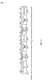
図4は、現在の開示のある態様に従う、PSMPフレーム内の例の情報フィールド400を示す。PSMPフレームはグループ・アドレスに対してアドレスしてもよく、データを送信および/または受信し得る各ユーザ局(STA)に対して、さまざまな局情報(STA−info)フィールドを運び得る。
Scheduling of Peer-to-Peer Transactions FIG. 4 shows an
STA−infoフィールド400の異なるフィールド場は、異なる機能を持ち得る。局識別(STA−ID)フィールド408は、STA−infoフィールド400に関連したSTAを識別し得る。PSMPダウンリンク送信時間(Downlink Transmission Time:DTT)スタート・オフセット・フィールド404は、STAにおいて、受信のための開始時間を識別し得るし、PSMP−DTT時間フィールド406はSTAの受信時間を識別し得る。一方で、PSMPアップリンク・送信時間(Uplink Transmission Time:UTT)スタート・オフセット・フィールド410は、STAからの送信の時間を識別してもよく、PSMP−UTT時間フィールド412は、STAからの送信に関して許容された時間の期間を識別し得る。
Different field fields of the STA-
各STAは、ピア・ノードの識別を知ることと同様に、送信するときと受信するときに、完全に知る必要があり得る。現在の開示では、ピア・ツー・ピア送信を適応させるようにPSMPメッセージの能力を広げることが提案されている。現在の開示の1つの態様では、STA−infoタイプ・フィールド402の値は、STA−infoフィールド400が直接リンク・セットアップ(Direct Link Setup:DLS)接続に基づいたSTA・ツー・STA送信に関して捧げられているということを示している定義された値(たとえば、3つの値)に向かう。指定されたビット414は、STA・ツー・STAのDLS送信に関するチャンネルを定義するように利用され得る。送信チャンネルは、指定されたビット414の値を変化させることでスイッチされ得る。
STAはAPからPSMPメッセージを受信するときに、STAは、それ自身に関するSTA−infoフィールドを見つけるためにメッセージに目を通し得る。STA−infoタイプ・フィールドから、STAは、割り当ての型、つまり、AP−STA通信またはDLS通信を識別し得る。もしも、STA(たとえば、STA1)に関連したSTA−infoフィールドが、DLS通信に関して識別されるなら、それでは、STA1が、このDLS通信に関する1つかそれ以上の可能性のある行先に関するPSMPメッセージをくまなく探し得る。
可能性のある行き先(たとえば、STA2とSTA3)がいったん識別されていると、もしも、PSMP−DTT開始オフセットとPSMP−DTT期間が、STA1のPSMP−UTTスタート・オフセットとPSMP−UTT期間とマッチするSTA2および/またはSTA3に関するSTA−infoフィールドがあるのなら、STA1は決まり得る。もしもSTA1が、たとえばSTA2と関連しているSTA−infoフィールドのマッチングを見つけるのなら、それから、STA1は、割り当てられたオフセットで、割り当てられた時間の期間に関して、STA2へデータを送信し始め得る。
Each STA may need to know completely when sending and receiving, as well as knowing the identity of the peer node. In the current disclosure, it is proposed to expand the capability of PSMP messages to accommodate peer-to-peer transmission. In one aspect of the current disclosure, the value of the STA-
When a STA receives a PSMP message from an AP, the STA may look through the message to find a STA-info field for itself. From the STA-info type field, the STA may identify the type of assignment, ie AP-STA communication or DLS communication. If the STA-info field associated with the STA (eg, STA1) is identified for DLS communication, then STA1 includes all of the PSMP messages for one or more possible destinations for this DLS communication. You can look for it.
Once possible destinations (eg, STA2 and STA3) have been identified, the PSMP-DTT start offset and PSMP-DTT period will match STA1's PSMP-UTT start offset and PSMP-UTT period. If there is a STA-info field for STA2 and / or STA3, STA1 can be determined. If STA1 finds a match for the STA-info field associated with STA2, for example, then STA1 may begin transmitting data to STA2 for the allocated time period at the allocated offset.
PSMPフレームは、たとえば、STA−infoフィールド400の指定されたフィールド414のように、6ビットのうち3ビット、を用いることで、チャンネル・スイッチを示すように利用することもでき得る。もしも、たとえば、APに対して、4つの隣接した20MHzのチャンネルが利用できるのなら、異なる3ビットのパターンが、1つかそれ以上の20MHzチャンネルの異なる組み合わせを示し得ることになる。もしも、チャンネル・スイッチ・オプションが利用できるなら、STA1は、オフセットと期間フィールドに加えて1つかそれ以上のピアと送信チャンネルをマッチさせる必要もあり得る、ということにも注意が必要だろう。
The PSMP frame may be used to indicate a channel switch by using 3 bits out of 6 bits, for example, a designated
STAが、PSMPフレームで定義されるどの時間の間にもスリープ・モードで動作することができ得る、ということにも、注意が必要だろう。さらに、STAは、PSMPフレームで確立された送信と干渉しない任意の送信に関する無線チャンネルにアクセスすることが可能であり、ここで、その無線チャンネルはPSMPフレームに示されることはないだろう。たとえば、STAは、PSMPメッセージにカバーされることなく、無線チャンネルに含まれ得る。 It should also be noted that the STA may be able to operate in sleep mode for any time defined in the PSMP frame. In addition, the STA can access a radio channel for any transmission that does not interfere with the transmission established in the PSMP frame, where the radio channel will not be indicated in the PSMP frame. For example, a STA can be included in a wireless channel without being covered by a PSMP message.
図5は、現在の開示のある態様に従う、多重通信のスケジューリングに関するAPで実行される例の動作500を説明している。502で、APは、装置間の多重通信に関するスケジュールを決定することもあり、ここで、スケジュールは、送信するための第1の装置(つまり、ピア・ノード)に関する時間と、受信するための第2の装置(つまり、もう1方のピア・ノード)に関する同じ時間とを示している。504で、APは、スケジュールを第1の装置と第2の装置に送信し得る。多重通信は、装置のペアの間(つまり、ピア・ノードの間)に確立された多重DLS通信を含み得る。
FIG. 5 illustrates
図6は、現在の開示のある態様に従う第2の装置との通信を確立することに関する、第1の装置で実行される例の動作600を説明している。602で、第1の装置は、通信に関する時間を示す制御メッセージを受信し得る。604で、通信に関する割り当てられた同じ時間を持つ第2の装置は識別されている。606で、第1の装置は時間中に、第2の装置と通信し得る。
FIG. 6 illustrates
APスケジュールド・ピア・ツー・ピア・トランザクションを開始すること
1つかそれ以上のピア・ツー・ピア・トランザクションをスケジュールするためのアクセス・ポイントに関する順序では、アクセス・ポイントは、STAでのバックログされたピア・ツー・ピア・トラフィックに気づく必要があり得る。APをバックログ情報とともに提供することに関して、現在の開示ではさまざまな方法が提案されている。
現在の開示の1つの態様では、APはバックログ情報を決定するためにDLSデータ・トラフィックを聞くかもしれず、ここで、決定されたバックログ情報は将来のDLSデータ・トラフィック転送をスケジュールするために用いられる可能性がある。もう1方の態様では、APが、決定論的なバックオフ手順を用いてDLS送信に関する要求の送信時間をスケジュールし得る。APは、DLS能力のあるSTAのサブセットに関するバックオフ・カウントとともにメッセージを発送する可能性があり、それから、ピア・ツー・ピア・バッファ・レベルに関連する応答に関して待ち得る。まだもう1方の態様では、APは、どれくらい多く特定のDLSフローがスケジュールされる必要があり得るのかを決定するために、DLSフローのトラフィック仕様(Traffic Specification:TSPEC)を利用し得る。
Initiating an AP scheduled peer-to-peer transaction In an order with respect to access points for scheduling one or more peer-to-peer transactions, the access points are backlogged at the STA. You may need to be aware of peer-to-peer traffic. Various methods have been proposed in the current disclosure for providing APs with backlog information.
In one aspect of the current disclosure, the AP may hear DLS data traffic to determine backlog information, where the determined backlog information is used to schedule future DLS data traffic transfers. May be used. In another aspect, the AP may schedule a transmission time for a request for DLS transmission using a deterministic backoff procedure. The AP may route a message with a backoff count for a subset of DLS capable STAs, and then wait for a response related to the peer to peer buffer level. In yet another aspect, the AP may utilize DLS flow traffic specification (TSPEC) to determine how many specific DLS flows may need to be scheduled.
上で説明した方法のさまざまなオペレーションは、対応する機能を実行できる任意の適した手段によって実行され得る。手段は、さまざまなハードウェアおよび/またはソフトフェアのコンポーネントおよび/またはモジュールを含む可能性があり、回路に限るわけではないが、特定用途向け集積回路(application specific integrate circuit:ASIC)、またはプロセッサを含んでいる。一般的に、図に説明されているオペレーションがあるところでは、それらのオペレーションは、似たナンバリングを持つ、対応する手段プラス機能のコンポーネントを持ち得る。たとえば、ブロック502−504は図5と図6に説明されており、図5Aと図6Aに説明されている回路ブロック502A−504Aと602A−606Aに対応する。
The various operations of the methods described above may be performed by any suitable means that can perform the corresponding function. Means may include various hardware and / or software components and / or modules, and are not limited to circuits, but may include application specific integrated circuits (ASICs), or processors. Contains. In general, where there are operations illustrated in the figure, those operations may have corresponding means plus functional components with similar numbering. For example, blocks 502-504 are described in FIGS. 5 and 6 and correspond to
ここで用いられたように、「決定する(determining)」という言葉は、広範囲の行動を含んでいる。たとえば、「決定する(determining)」は、計算する、演算するする、処理する、導き出す、調査する、検討する(たとえば、テーブル、データベース、または他のデータ構造を検討する)、確認する、などを含み得る。また、「決定する(determining)」は、受信する(たとえば、情報を受信する)、アクセスする(たとえば、メモリのデータにアクセスする)、などを含み得る。また「決定する(determining)は、解決する、選択する(select)、選ぶ(choose)、確立する、などを含み得る。 As used herein, the term “determining” includes a wide range of actions. For example, “determining” means calculating, computing, processing, deriving, examining, examining (eg, examining a table, database, or other data structure), confirming, etc. May be included. Also, “determining” can include receiving (eg, receiving information), accessing (eg, accessing data in a memory) and the like. Also, “determining” may include resolving, selecting, choosing, establishing, and the like.
ここで用いられたように、項目のリスト「のうち少なくとも1つ」に言及するフレーズは、単一のものも含み、それらの項目のどの組み合わせにも言及する。1つの例として、「a、b、またはcのうち少なくとも1つ」ということは、a,b,c、a−b,a−c,b−c、そしてa−b−c、をカバーするよう意図される。 As used herein, a phrase referring to “at least one of a list of items” includes a single one and also refers to any combination of those items. As one example, “at least one of a, b, or c” covers a, b, c, ab, ac, bc, and abc. Intended to be.
上で説明した方法の様々なオペレーションは、様々なハードウェアおよび/またはソフトウェア・コンポーネント、回路および/またはモジュールのような、オペレーションを実行できる任意の適した手段によって実行され得る。一般的に、図に説明されたどのオペレーションも、オペレーションを実行できるような、対応する機能的手段によって実行され得る。 The various operations of the methods described above may be performed by any suitable means capable of performing the operations, such as various hardware and / or software components, circuits and / or modules. In general, any of the operations described in the figures can be performed by corresponding functional means that can perform the operations.
現在の開示と関連して説明された様々な実例となるロジカル・ブロック、モジュール、回路は、汎用目的プロセッサ、デジタル信号プロセッサ(digital signal proceeor:DSP)、特定用途向け集積回路(application integrated circuit:ASIC)、フィールド・プログマブル・ゲート・アレイ信号(field programmble gate array signal:FPGA)または他のプログマブル・ロジック・デバイス(programmable logic device:PLD)、ディスクリート・ゲートまたはトランジスタ・ロジック、ディスクリート・ハードウェア・コンポーネントまたはここで説明された機能を実行するように設計されたどの組み合わせでもインプリメントまたはパフォームされ得る。汎用目的プロセッサはマイクロプロセッサであり得るが、代案では、プロセッサは、商業的に利用できる、プロセッサ、コントローラ、マイクロコントローラ、またはステート・マシーンであり得る。プロセッサはたとえば、DSPとマイクロプロセッサの組み合わせ、複数のマイクロプロセッサ、DSPコアとコンジャンクションの1つかそれ以上のマイクロプロセッサ、または他のそのような構成のような、コンピューティング・デバイスのコンビネーションとしてインプリメントされ得ることもある。現在の開示と関連して説明された様々な実例となる回路は、ハードウェア・コンポーネント、ソフトウェア・コンポーネント、ファームウェア・コンポーネント、またはそれらの組み合わせを含むようにインプリメントされ得ることもある。 The various illustrative logical blocks, modules, and circuits described in connection with the current disclosure are general purpose processors, digital signal processors (DSPs), application integrated circuits (ASICs). ), Field programmable gate array signal (FPGA) or other programmable logic device (PLD), discrete gate or transistor logic, discrete hardware component Any set designed to perform the functions described here It may be implemented or path form in together. A general purpose processor may be a microprocessor, but in the alternative, the processor may be any commercially available processor, controller, microcontroller or state machine. A processor is implemented as a combination of computing devices such as, for example, a combination of a DSP and a microprocessor, multiple microprocessors, one or more microprocessors in a DSP core and junction, or other such configuration. Sometimes you get. Various illustrative circuits described in connection with the current disclosure may be implemented to include hardware components, software components, firmware components, or combinations thereof.
現在の開示と関連して説明された方法またはアルゴリズムのステップは、プロセッサにより実行される、ハードウェア、ソフトウェア・モジュールにおいて、または、2つの組み合わせにおいて、具体化され得る。ソフトウェア・モジュールは、技術的に知られたどの形式の記憶媒体にも存在し得る。用いられる可能性のある記憶媒体のいくつかの例は、ランダム・アクセス・メモリ(random access memory:RAM)、読み出し専用メモリ(read only memory:ROM)、フラッシュ・メモリ、EPROMメモリ、EEPROMメモリ、レジスタ、ハード・ディスク、リムーバブル・ディスク、CD−ROMなどを含んでいる。ソフトウェア・モジュールはシングルの命令、または多くの命令を含んでもよく、異なるプログラムの間で、そして多重記憶媒体にわたって、様々な異なるコード・セグメントに分布し得る。記憶媒体は、記憶媒体から情報を読み取ることができ、記憶媒体へ情報を書き込むことができるプロセッサのような、プロセッサへカップルされ得る。代案では、記憶媒体はプロセッサへ必須になり得る。 The method or algorithm steps described in connection with the current disclosure may be embodied in hardware, software modules or a combination of the two executed by a processor. A software module may reside in any form of storage medium that is known in the art. Some examples of storage media that may be used are: random access memory (RAM), read only memory (ROM), flash memory, EPROM memory, EEPROM memory, registers , Hard disks, removable disks, CD-ROMs and the like. A software module may contain a single instruction, or many instructions, and may be distributed in a variety of different code segments between different programs and across multiple storage media. A storage medium may be coupled to a processor, such as a processor that can read information from, and write information to, the storage medium. In the alternative, the storage medium may be integral to the processor.
ここで開示された方法は、説明された方法をアチーブするための1つかそれ以上のステップまたはアクションを含む。方法のステップおよび/またはアクションは、請求項の範囲から離れることなく、お互いに交換され得る。言い換えると、ステップまたはアクションの特定の順序が特定されないで、特定のステップおよび/またはアクションの順序および/または使用は、請求項の範囲から離れることなく修正され得る。 The methods disclosed herein include one or more steps or actions for achieving the described methods. The method steps and / or actions may be interchanged with one another without departing from the scope of the claims. In other words, without a specific order of steps or actions being specified, the order and / or use of specific steps and / or actions may be modified without departing from the scope of the claims.
説明された機能は、ハードウェア、ソフトウェア、ファームウェア、またはそれらの組み合わせにおいて、インプリメントされ得る。もしもソフトウェアでインプリメントされるなら、機能は、コンピュータ可読媒体に対する1つかそれ以上の命令として記憶され得る。記憶媒体は、コンピュータによってアクセスされることのできる任意の利用可能な媒体であり得る。一例として、そして限るわけではないが、そのようなコンピュータ可読媒体は、RAM、ROM、EEPROM、CD−ROMまたは、他の光学ディスク記憶、磁気ディスク記憶または他の磁気記憶装置、または、命令またはデータ構造の形式の望ましいプログラム・コードを運ぶまたは記憶するのに使用されることができ、コンピュータにアクセスされることのできる任意の他の媒体を含むことができる。ここで用いられた、ディスク(disk)とディスク(disc)は、コンパクト・ディスク(compact disc:CD)、レーザ・ディスク、光学ディスク、デジタル多用途ディスク(digital versatile disc:DVD)、フロッピー(登録商標)・ディスク、そしてブルーレイ・ディスクを含んでおり、ここでディスク(disk)は通常磁気的にデータを再生し、一方でディスク(disc)はレーザにより光学的にデータを再生する。 The described functionality may be implemented in hardware, software, firmware, or a combination thereof. If implemented in software, the functions may be stored as one or more instructions on a computer-readable medium. A storage media may be any available media that can be accessed by a computer. By way of example and not limitation, such computer readable media may be RAM, ROM, EEPROM, CD-ROM, or other optical disk storage, magnetic disk storage or other magnetic storage device, or instructions or data Any other medium that can be used to carry or store the desired program code in the form of a structure and that can be accessed by a computer can be included. As used herein, the disc and the disc are a compact disc (CD), a laser disc, an optical disc, a digital versatile disc (DVD), a floppy (registered trademark). Discs, and Blu-ray discs, where the disc normally reproduces data magnetically, while the disc reproduces data optically with a laser.
このように、ある態様は、ここで表したオペレーションを実行することに関する、コンピュータ・プログラム製品を含み得る。たとえば、そのようなコンピュータ・プログラム製品は、その上に記憶された(および/または符号化された)命令を持つコンピュータ可読媒体を含むこともあり、命令は、ここで説明した操作を実行するように1つかそれ以上のプロセッサによって実行できる。ある態様に関しては、コンピュータ・プログラム製品は包装材料を含み得る。 Thus, certain aspects may include a computer program product relating to performing the operations described herein. For example, such a computer program product may include a computer-readable medium having instructions stored (and / or encoded) thereon, such that the instructions perform the operations described herein. Can be executed by one or more processors. For certain aspects, the computer program product may include packaging material.
ソフトウェアまたは命令は、伝送媒体を超えて送信されることもあり得る。たとえば、もしもソフトウェアが、ウェブサイト、サーバ、または他の、同軸ケーブル、光ファイバ・ケーブル、ツイステッド・ペア、デジタル加入者線(digital subcriber line:DSL)、または、赤外線、ラジオ波、マイクロウェーブ波のような無線技術を用いるリモート・ソースから送信されるなら、そのとき、同軸ケーブル、光ファイバ・ケーブル、ツイステッド・ペア、DSL、または、赤外線、ラジオ波、マイクロウェーブ波のような無線技術が伝送媒体の定義の中に含まれる。 Software or instructions may be transmitted over a transmission medium. For example, if the software is a website, server, or other, coaxial cable, fiber optic cable, twisted pair, digital subscriber line (DSL), or infrared, radio, microwave If transmitted from a remote source using wireless technology such as coaxial cable, fiber optic cable, twisted pair, DSL, or wireless technology such as infrared, radio, microwave Included in the definition of
さらに、ここで説明された方法と技術を実行することに関する、モジュールと他の適切な手段は、適切なように、ユーザ端末および/または基地局によってダウンロードおよび/または別に得ることができるというのは、十分理解されるべきである。たとえば、そのようなデバイスは、ここで説明された方法を実行することに関する手段の転送を容易にするようにサーバにカップルされることができる。代わりに、ここで説明された様々な方法は記憶手段(たとえば、RAM、ROM、コンパクト・ディスク(CD)またはフロッピー(登録商標)・ディスクのような物理的な記憶媒体)を経由して提供されることができて、そのようなユーザ端末および/または基地局はデバイスに対する記憶手段を接続する、または提供することに対する様々な方法を得ることができる。さらに、デバイスに対するここで説明された方法と技術を提供することに関する他の適した技術は、利用されることができる。 Further, modules and other suitable means for performing the methods and techniques described herein may be downloaded and / or obtained separately by user terminals and / or base stations as appropriate. Should be well understood. For example, such a device can be coupled to a server to facilitate the transfer of means related to performing the methods described herein. Instead, the various methods described herein are provided via storage means (eg, physical storage media such as RAM, ROM, compact disk (CD) or floppy disk). Such user terminals and / or base stations can obtain various ways to connect or provide storage means for the device. In addition, other suitable techniques relating to providing the methods and techniques described herein for devices can be utilized.
請求項は、上で説明された正確な構成とコンポーネントに制限されないということは理解されるべきである。様々な修正、変化、変動は、配置、動作、上で説明された方法と装置の詳細において、請求項の範囲から離れることなくなされ得る。 It is to be understood that the claims are not limited to the precise configuration and components illustrated above. Various modifications, changes and variations may be made in the arrangement, operation and details of the methods and apparatus described above without departing from the scope of the claims.
前述のものが現在の開示の態様に指向される一方で、開示の他とさらなる態様は、その基本的な視点から離れることなく工夫されることもあり、その視点は以下の請求項で決定される。
以下に本件出願当初の特許請求の範囲に記載された発明を付記する。
[1]無線通信のための方法であって、装置間の多重通信のためのスケジュールを決定することであって、前記スケジュールが送信する第1の装置のための時間と受信する第2の装置のための同じ前記時間を示す、決定することと、前記第1の装置と前記第2の装置に対する前記スケジュールを送信することとを備える、方法。
[2]前記スケジュールが、制御メッセージにおいて前記第1の装置と前記第2の装置に送信される、[1]の方法。
[3]前記制御メッセージは、前記第1の装置と前記第2の装置がダイレクト・リンク・セットアップ(DLS)接続を用いて通信するべきであることを示す前記第1の装置と前記第2の装置のためのタイプ・フィールドを備える、[2]の方法。
[4]前記制御メッセージは前記通信のうちの1つに関して使用される無線チャンネルを示すビットのシーケンスを備える、[2]の方法。
[5]前記装置のサブセットに対してバックオフ・カウントとともにメッセージを送信することと、装置の前記サブセットから、前記メッセージに対する1つ又はそれ以上の応答を受信することであって、各応答は前記サブセットから前記装置のうちの1つに関連する通信バッファのレベルに関する情報を備える、受信することと、前記1つ又はそれ以上の応答に基づいて前記通信のための前記装置から要求をスケジューリングすることとをさらに備える、[1]の方法。
[6]通信のトラフィックの仕様(TSPEC)に基づいて各通信に関するスケジュールを決定することをさらに備える、[1]の方法。
[7]バックログ情報を決定するために前記通信を聞くことと、前記バックログ情報に基づいて前記装置間の別の通信をスケジューリングすることとをさらに備える、[1]の方法。
[8]前記多重通信は、前記装置間のペアの間で確立された多重データ・リンク・セットアップ(DLS)通信を備える、[1]の方法。
[9]無線通信のための装置であって、装置間の多重通信のためのスケジュールを決定するように構成される回路であって、前記スケジュールが送信する第1の装置のための時間と受信する第2の装置のための同じ前記時間を示す、回路と、前記スケジュールを前記第1の装置と前記第2の装置に前記スケジュールを送信するように構成される送信機とを備える、装置。
[10]前記スケジュールが、制御メッセージにおいて前記第1の装置と前記第2の装置に対して送信される、[9]の装置。
[11]前記制御メッセージは、前記第1の装置と前記第2の装置はダイレクト・リンク・セットアップ(DLS)接続を用いて通信するべきであること示す、前記第1の装置と前記第2の装置のためのタイプ・フィールドを備える、[10]の装置。
[12]前記制御メッセージは、前記通信のうちの1つに関して用いられる無線チャンネルを示すビットのシーケンスを備える、[10]の装置。
[13]前記送信機は、また、前記装置のサブセットにバックオフ・カウントとともにメッセージを送信するように構成され、前記装置は、装置の前記サブセットから前記メッセージに対する1つ又はそれ以上の応答を受信するように構成される受信機であって、各応答は、前記サブセットからの前記装置のうちの1つに関連した通信バッファのレベルに関する情報を備える、受信機と、前記1つ又はそれ以上の応答に基づく前記通信のための前記装置から要求をスケジューリングするように構成されるスケジューラとをさらに備える、[9]の装置。
[14]前記通信のトラフィックの仕様(TSPEC)に基づく各々の前記通信に関するスケジュールを決定するために構成されるスケジューラをさらに備える、[9]の装置。
[15]バックログ情報を決定するために前記通信を聞くように構成される受信機と、前記バックログ情報に基づいた前記装置間の他の通信をスケジュールするように構成されるスケジューラとをさらに備える、[9]の装置。
[16]前記多重通信は、前記装置のペアの間で確立された多重データ・リンク・セットアップ(DLS)通信を備える、[9]の装置。
[17]無線通信のための装置であって、装置間の多重通信のためのスケジュールを決定するための手段であって、前記スケジュールが送信する第1の装置のための時間と受信する第2の装置のための同じ時間を示す、決定するための手段と、前記スケジュールを第1の装置と第2の装置に前記スケジュールを送信するための手段とを備える、装置。
[18]前記スケジュールは、制御メッセージにおいて、前記第1の装置と前記第2の装置に対して送信される、[17]の装置。
[19]前記制御メッセージは、前記第1の装置と前記第2の装置がダイレクト・リンク・セットアップ(DLS)接続を用いて通信するべきだということを示す、前記第1の装置と前記第2の装置のためのタイプ・フィールドを備える、[18]の装置。
[20]前記制御メッセージは、前記通信のうちの1つに関して用いられる無線チャンネルを示すビットのシーケンスを備える、[18]の装置。
[21]送信するための前記手段は、さらに、バックオフ・カウントとともにメッセージを前記装置のサブセットへ送信するように構成され、前記装置は、装置の前記サブセットから前記メッセージへの1つ又はそれ以上の応答を受信するための手段であって、それぞれの応答が前記サブセットから前記装置のうちの1つに関連した通信バッファのレベルに関する情報を備える、受信するための手段と、前記装置から、1つ又はそれ以上の応答に基づいた前記通信に関して要求をスケジュールするための手段とをさらに備える、[17]の装置。
[22]前記通信のトラフィックの仕様(TSPEC)に基づいた前記通信の各々に関するスケジュールを決定するための手段をさらに備える、[17]の装置。
[23]バックログ情報を決定するための前記通信を聞くための手段と、前記バックログ情報に基づいた前記装置間の他の通信をスケジュールするための手段とをさらに備える、[17]の装置。
[24]前記多重通信は、前記装置のペアの間で確立された多重データ・リンク・セットアップ(DLS)通信を備える、[17]の装置。
[25]無線通信のためのコンピュータ・プログラム製品であって、装置間の多重通信のためのスケジュールを決定することであって、前記スケジュールが送信する第1の装置のための時間と受信する第2の装置のための同じ時間とを示す、決定することと、前記第1の装置と前記第2の装置に対して前記スケジュールを送信することとを実行できる命令を備えるコンピュータ可読媒体を備える、コンピュータ・プログラム製品。
[26]少なくとも1つのアンテナと、無線ノード間の多重通信のためのスケジュールを決定するように構成される回路であって、前記スケジュールが送信する第1無線ノードのための時間と受信する第2無線ノードのための同じ時間とを示す、回路と、前記の少なくとも1つのアンテナを経由して前記スケジュールを前記第1無線ノードと前記第2無線ノードに対して送信するように構成された送信機とを備える、アクセス・ポイント。
[27]無線通信のための方法であって、第1の装置において、通信のための時間を示す制御メッセージを受信することと、通信に関して前記同じ時間を割り当てられた第2の装置を識別することと、前記時間中に前記第2の装置と通信することとを備える、方法。
[28]前記制御メッセージは、前記第1の装置と前記第2の装置がダイレクト・リンク・セットアップ(DLS)接続を用いて通信するべきであることを示す、前記第1の装置と前記第2の装置のためのタイプ・フィールドを備える、[27]の方法。
[29]前記制御メッセージは、前記通信に関して用いられる無線チャンネルを示すビットのシーケンスを備える、[27]の方法。
[30]前記制御メッセージはパワー・マネージメント・メッセージを備える、[27]の方法。
[31]前記パワー・マネージメント・メッセージは、前記IEEE 802.11nのパワー・セーブ・マルチ・ポール(PSMP)メッセージを備える、[30]の方法。
[32]前記第2の装置を識別することは、前記第1の装置に関連するフィールドを見つけるために前記パワー・マネージメント・メッセージをスキャンすることと、前記第1の装置からデータ送信の時間を示す前記フィールドにおける第1の値と前記第2の装置でデータ受信に関する開始時間を示す別のフィールドとをマッチさせることと、前記第1の装置からデータ送信に関する時間の期間を示す前記フィールドにおける第2の値と前記第2の装置でデータ受信に関する時間の期間を示す前記第2の装置と関連したもう一方のフィールドにおける第2の値とをマッチさせるように前記パワー・マネージメント・メッセージをスキャンすることとを備える、[30]の方法。
[33]前記第1の装置によって用いられる無線チャンネルを示す前記フィールドにおけるビットのシーケンスと、前記第2の装置によって用いられる無線チャンネルを示すもう一方のフィールドにおけるビットの別のシーケンスとをマッチさせるように前記パワー・マネージメント・メッセージをスキャンすることをさらに備える、[32]の方法。
[34]前記制御メッセージに定義された任意の時間中にスリープ・モードにおいて動作することをさらに備える、[27]の方法。
[35]前記制御メッセージに基づいて確立されたダイレクト・リンク・セットアップ(DLS)接続を用いて通信することに干渉しない送信に関して、前記制御メッセージに示されていない無線チャンネルにアクセスすることをさらに備える、[27]の方法。
[36]前記アクセスすることは、前記無線チャンネルにおいて競合することを備える、[35]の方法。
[37]無線通信のための装置であって、通信のための時間を示す制御メッセージを受信するように構成される受信機と、通信に関する前記同じ時間を割り当てられた別の装置を識別するように構成される回路と、前記時間中にもう一方の装置と通信するように構成されるトランシーバとを備える、装置。
[38]前記制御メッセージは、前記装置と前記別の装置がダイレクト・リンク・セットアップ(DLS)接続を用いて通信すべきであることを示す前記装置と前記別の装置のためのタイプ・フィールドを備える、[37]の装置。
[39]前記制御メッセージは、前記通信に関して用いられる無線チャンネルを示すビットのシーケンスを備える、[37]の装置。
[40]前記制御メッセージは、パワー・マネージメント・メッセージを備える、[37]の装置。
[41]前記パワー・マネージメント・メッセージは前記IEEE 802.11nのパワー・セーブ・マルチ・ポール(PSMP)メッセージを備える、[40]の装置。
[42]もう一方の装置を識別するように構成される前記回路は、前記装置と関連したフィールドを見つけるように前記パワー・マネージメント・メッセージをスキャンするように構成される走査回路を備え、前記走査回路は、前記装置からデータ送信の時間を示す前記フィールドにおける第1の値ともう一方の装置でのデータ受信に関する開始時間を示す別のフィールドにおける第1の値とをマッチさせるように、そして前記装置からデータ送信に関する時間の期間を示す前記フィールドにおける第2の値ともう一方の装置でのデータ受信に関する時間の期間を示すもう一方の装置に関連したもう一方のフィールドにおける第2の値とをマッチさせるように、前記パワー・マネージメント・メッセージをスキャンするようにも構成される、[40]の装置。
[43]前記走査回路は、さらに、前記装置によって用いられる無線チャンネルを示す前記フィールドにおけるビットのシーケンスともう一方の装置によって用いられる無線チャンネルを示すもう一方のフィールドにおけるビットの別のシーケンスとをマッチさせるように前記パワー・マネージメント・メッセージをスキャンするように構成される、[42]の装置。
[44]前記制御メッセージにおいて定義された任意の時間中にスリープ・モードで動作するように構成された低電力回路をさらに備える、[37]の装置。
[45]前記送信機は、また、前記制御メッセージに基づいて確立されたダイレクト・リンク・セットアップ(DLS)接続を用いて通信することに干渉しない送信に関する無線チャンネルにアクセスするように構成され、前記無線チャンネルは前記パワー・セーブ、マルチ・ポール制御メッセージにおいて示されない、[37]の装置。
[46]前記送信機は、また、前記無線チャンネルにおいて競合するように構成される、[45]の装置。
[47]通信に関する時間を示す制御メッセージを受信するための手段と、通信に関する前記同じ時間を割り当てられた別の装置を識別するための手段と、前記時間中にもう一方の装置と通信するための手段とを備える、無線通信のための装置。
[48]前記制御メッセージは、前記装置と前記別の装置がダイレクト・リンク・セットアップ(DLS)接続を用いて通信するべきであることを示す、前記装置と前記別の装置のためのタイプ・フィールドを備える、[47]の装置。
[49]前記制御メッセージは、前記通信に関して用いられる無線チャンネルを示すビットのシーケンスを備える、[47]の装置。
[50]前記制御メッセージはパワー・マネージメント・メッセージを備える、[47]の装置。
[51]前記パワー・マネージメント・メッセージは、前記IEEE 802.11nのパワー・セーブ・マルチ・ポール(PSMP)メッセージを備える、[50]の装置。
[52]前記別の装置を識別するための前記の手段は、前記装置と関連したフィールドを見つけるように前記パワー・マネージメント・メッセージをスキャンするための手段と、
前記装置からデータ送信の時間を示す前記フィールドにおける第1の値と前記別の装置でデータ受信に関する開始時間を示す別のフィールドにおける第1の値とをマッチさせ、前記装置からデータ送信に関する時間の期間を示す前記フィールドにおける第2の値ともう一方の装置でデータ受信に関する時間の期間を示す、前記別の装置と関連した前記別のフィールドにおける第2の値とをマッチさせるように、前記パワー・マネージメント・メッセージをスキャンするための手段とを備える、[50]の装置。
[53]前記装置によって用いられた無線チャンネルを示す前記フィールドにおけるビットのシーケンスと、もう一方の装置によって用いられた無線チャンネルを示すもう一方のフィールドにおけるビットの別のシーケンスとをマッチさせるように前記パワー・マネージメント・メッセージをスキャンするための手段をさらに備える、[52]の装置。
[54]前記制御メッセージで定義された任意の時間中にスリープ・モードで動作するための手段をさらに備える、[47]の装置。
[55]前記制御メッセージに基づいて確立されたダイレクト・リンク・セットアップ(DLS)接続を用いて通信することに干渉しない送信に関する、前記制御メッセージに示されていない無線チャンネルにアクセスするための手段をさらに備える、[47]の装置。
[56]アクセスするための前記手段は前記無線チャンネルにおいて競合するための手段を備える、[55]の装置。
[57]無線通信のためのコンピュータ・プログラム製品であって、第1の装置で、通信に関する時間を示す制御メッセージを受信し、通信に関する前記同じ時間を割り当てられた第2の装置を識別し、前記時間中に前記第2の装置と通信する、ように実行できる命令を備えるコンピュータ可読媒体を備える、コンピュータ・プログラム製品。
[58]少なくとも1つのアンテナと、通信に関する時間を示す制御メッセージを、前記少なくとも1つのアンテナを経由して受信するように構成された受信機と、通信に関する前記同じ時間を割り当てられた別の無線ノードを識別するように構成された回路と、前記時間中にもう一方の無線ノードと、前記少なくとも1つのアンテナを経由して通信するように構成された送信機とを備える、無線ノード。
While the foregoing is directed to aspects of the present disclosure, other and further aspects of the disclosure may be devised without departing from its basic viewpoint, which is determined by the following claims. The
The invention described in the scope of the claims at the beginning of the present application is added below.
[1] A method for wireless communication, determining a schedule for multiplex communication between devices, wherein the schedule is a time for a first device to transmit and a second device to receive Determining the same time for, and transmitting the schedule for the first device and the second device.
[2] The method of [1], wherein the schedule is transmitted to the first device and the second device in a control message.
[3] The control message indicates that the first device and the second device indicate that the first device and the second device should communicate using a direct link setup (DLS) connection. The method of [2], comprising a type field for the device.
[4] The method of [2], wherein the control message comprises a sequence of bits indicating a radio channel used for one of the communications.
[5] sending a message with a backoff count to the subset of devices and receiving one or more responses to the message from the subset of devices, each response comprising the Receiving from a subset information relating to a level of a communication buffer associated with one of the devices and scheduling a request from the device for the communication based on the one or more responses The method of [1], further comprising:
[6] The method of [1], further comprising determining a schedule for each communication based on a communication traffic specification (TSPEC).
[7] The method of [1], further comprising listening to the communication to determine backlog information and scheduling another communication between the devices based on the backlog information.
[8] The method of [1], wherein the multiplex communication comprises multiple data link setup (DLS) communication established between the pair between the devices.
[9] An apparatus for wireless communication, a circuit configured to determine a schedule for multiplex communication between apparatuses, the time and reception for the first apparatus transmitted by the schedule An apparatus comprising: a circuit that indicates the same time for a second device to perform; and a transmitter configured to transmit the schedule to the first device and to the second device.
[10] The apparatus according to [9], wherein the schedule is transmitted to the first device and the second device in a control message.
[11] The control message indicates that the first device and the second device should communicate using a direct link setup (DLS) connection. [10] The device of [10], comprising a type field for the device.
[12] The apparatus of [10], wherein the control message comprises a sequence of bits indicating a radio channel used for one of the communications.
[13] The transmitter is also configured to send a message with a backoff count to the subset of devices, the device receiving one or more responses to the message from the subset of devices. A receiver configured to, each response comprising information regarding a level of a communication buffer associated with one of the devices from the subset; and the one or more of the receivers [9] The apparatus of [9], further comprising a scheduler configured to schedule requests from the apparatus for the communication based on responses.
[14] The apparatus of [9], further comprising a scheduler configured to determine a schedule for each of the communications based on traffic specifications (TSPEC) of the communications.
[15] A receiver configured to listen to the communication to determine backlog information; and a scheduler configured to schedule other communication between the devices based on the backlog information. The apparatus according to [9].
[16] The apparatus of [9], wherein the multiplex communication comprises multiple data link setup (DLS) communication established between the pair of devices.
[17] A device for wireless communication, means for determining a schedule for multiplex communication between devices, the time for the first device transmitted by the schedule and the second received An apparatus comprising: means for determining the same time for a plurality of devices; and means for transmitting the schedule to the first device and the second device.
[18] The device according to [17], wherein the schedule is transmitted to the first device and the second device in a control message.
[19] The control message indicates that the first device and the second device should communicate using a direct link setup (DLS) connection. [18] The device of [18], comprising a type field for the device.
[20] The apparatus of [18], wherein the control message comprises a sequence of bits indicating a radio channel used for one of the communications.
[21] The means for transmitting is further configured to transmit a message with a backoff count to the subset of devices, the device comprising one or more of the devices from the subset to the message. Means for receiving, wherein each response comprises information about a level of a communication buffer associated with one of the devices from the subset, and from the device, 1 [17] The apparatus of [17], further comprising means for scheduling a request for said communication based on one or more responses.
[22] The apparatus of [17], further comprising means for determining a schedule for each of the communications based on a traffic specification (TSPEC) of the communications.
[23] The apparatus according to [17], further comprising: means for listening to the communication for determining backlog information; and means for scheduling another communication between the apparatuses based on the backlog information. .
[24] The apparatus of [17], wherein the multiplex communication comprises multiple data link setup (DLS) communication established between the pair of apparatuses.
[25] A computer program product for wireless communication, wherein a schedule for multiplex communication between devices is determined, the time for the first device that the schedule transmits and the first time received. Comprising a computer readable medium comprising instructions capable of performing a determination indicating the same time for two devices and transmitting the schedule to the first device and the second device; Computer program product.
[26] A circuit configured to determine a schedule for multiplex communication between at least one antenna and radio nodes, wherein the schedule transmits a time for a first radio node to receive and a second to receive A transmitter configured to transmit the schedule to the first wireless node and the second wireless node via the circuit and the at least one antenna indicating the same time for the wireless node And an access point.
[27] A method for wireless communication, wherein a first device receives a control message indicating a time for communication, and identifies a second device assigned the same time for communication And communicating with the second device during the time period.
[28] The control message indicates that the first device and the second device should communicate using a direct link setup (DLS) connection. The method of [27], comprising a type field for a device of:
[29] The method of [27], wherein the control message comprises a sequence of bits indicating a radio channel used for the communication.
[30] The method of [27], wherein the control message comprises a power management message.
[31] The method of [30], wherein the power management message comprises the IEEE 802.11n power save multi-pole (PSMP) message.
[32] Identifying the second device includes scanning the power management message to find a field associated with the first device, and a time for data transmission from the first device. Matching a first value in the indicated field with another field indicating a start time for data reception at the second device; and a second value in the field indicating a period of time for data transmission from the first device. The power management message is scanned to match a value of 2 with a second value in the other field associated with the second device indicating a period of time for data reception at the second device The method according to [30], comprising:
[33] Matching the sequence of bits in the field indicating the radio channel used by the first device with another sequence of bits in the other field indicating the radio channel used by the second device The method of [32], further comprising: scanning the power management message.
[34] The method of [27], further comprising operating in a sleep mode for any time defined in the control message.
[35] Further comprising accessing a radio channel not indicated in the control message for transmissions that do not interfere with communicating using a direct link setup (DLS) connection established based on the control message. [27] The method.
[36] The method of [35], wherein the accessing comprises competing in the wireless channel.
[37] An apparatus for wireless communication, the receiver configured to receive a control message indicating a time for communication, and another apparatus assigned the same time for communication And a transceiver configured to communicate with the other device during the time period.
[38] The control message includes a type field for the device and the other device indicating that the device and the other device should communicate using a direct link setup (DLS) connection. The apparatus according to [37].
[39] The apparatus of [37], wherein the control message comprises a sequence of bits indicating a radio channel used for the communication.
[40] The apparatus according to [37], wherein the control message includes a power management message.
[41] The apparatus of [40], wherein the power management message comprises the IEEE 802.11n power save multi-pole (PSMP) message.
[42] The circuit configured to identify another device comprises a scanning circuit configured to scan the power management message to find a field associated with the device; A circuit to match a first value in the field indicating a time of data transmission from the device with a first value in another field indicating a start time for data reception at the other device; and A second value in the field indicating a period of time for data transmission from a device and a second value in the other field associated with the other device indicating a period of time for data reception at the other device. Also configured to scan the power management message to match, 40] of the device.
[43] The scanning circuit further matches a sequence of bits in the field indicating a radio channel used by the device with another sequence of bits in the other field indicating a radio channel used by the other device. [42] The apparatus of [42], configured to scan the power management message.
[44] The apparatus of [37], further comprising a low power circuit configured to operate in a sleep mode during any time defined in the control message.
[45] The transmitter is also configured to access a radio channel for transmission that does not interfere with communicating using a direct link setup (DLS) connection established based on the control message; [37] The apparatus of [37], wherein a radio channel is not indicated in the power save, multi-pole control message.
[46] The apparatus of [45], wherein the transmitter is also configured to compete in the wireless channel.
[47] means for receiving a control message indicating a time related to communication; means for identifying another device assigned the same time related to communication; and for communicating with the other device during said time An apparatus for wireless communication, comprising:
[48] The control message indicates a type field for the device and the other device indicating that the device and the another device should communicate using a direct link setup (DLS) connection. The apparatus of [47].
[49] The apparatus of [47], wherein the control message comprises a sequence of bits indicating a radio channel used for the communication.
[50] The apparatus of [47], wherein the control message comprises a power management message.
[51] The apparatus of [50], wherein the power management message comprises the IEEE 802.11n power save multi-pole (PSMP) message.
[52] The means for identifying the another device comprises means for scanning the power management message to find a field associated with the device;
The first value in the field indicating the time for data transmission from the device is matched with the first value in another field indicating the start time for data reception in the other device, and the time for data transmission from the device is matched. The power to match a second value in the field indicating a period with a second value in the other field associated with the other device indicating a period of time for data reception at the other device. [50] The apparatus of [50], comprising: means for scanning management messages.
[53] The sequence of bits in the field indicating a radio channel used by the device is matched with another sequence of bits in the other field indicating a radio channel used by the other device. [52] The apparatus of [52], further comprising means for scanning a power management message.
[54] The apparatus of [47], further comprising means for operating in a sleep mode during any time defined in the control message.
[55] Means for accessing a radio channel not indicated in the control message for transmissions that do not interfere with communication using a direct link setup (DLS) connection established based on the control message. The apparatus according to [47], further comprising:
[56] The apparatus of [55], wherein the means for accessing comprises means for competing in the wireless channel.
[57] A computer program product for wireless communication, wherein a first device receives a control message indicating a time related to communication, and identifies a second device assigned the same time related to communication; A computer program product comprising a computer readable medium comprising instructions executable to communicate with the second device during the time period.
[58] At least one antenna and a receiver configured to receive a control message indicating a time related to communication via the at least one antenna, and another radio assigned the same time related to communication. A wireless node comprising a circuit configured to identify a node, another wireless node during the time, and a transmitter configured to communicate via the at least one antenna.
Claims (46)
装置間の多重通信のためのスケジュールをデバイスにおいて決定することと、ここで、前記スケジュールは、送信する第1の装置のための時間と受信する第2の装置のための同じ前記時間を示す、
制御メッセージの第1の局情報フィールドで前記第1の装置に、制御メッセージの第2の局情報フィールドで前記第2の装置に前記スケジュールを送信することと
を備え、
ここで、前記第1の局情報フィールドと前記第2の局情報フィールドは、前記第1の装置と前記第2の装置がダイレクト・リンク・セットアップ通信を用いて通信するべきであることを示すタイプ・フィールドを備える、方法。 A method for scheduling wireless communication between devices comprising:
Determining at a device a schedule for multiplex communication between devices, wherein the schedule indicates a time for a first device to transmit and a same time for a second device to receive;
Transmitting the schedule to the first device in a first station information field of a control message and to the second device in a second station information field of a control message;
Here, the first station information field and the second station information field indicate that the first device and the second device should communicate using direct link setup communication. A method comprising a field.
装置の前記サブセットから、前記メッセージに対する1つ又はそれ以上の応答を受信することであって、各応答は前記サブセットから前記装置のうちの1つに関連する通信バッファのレベルに関する情報を備える、受信することと、
前記1つ又はそれ以上の応答に基づいて前記通信に関して前記装置から要求をスケジューリングすることと
をさらに備える、請求項1の方法。 Sending a message with a backoff count to a subset of the devices;
Receiving one or more responses to the message from the subset of devices, each response comprising information regarding a level of a communication buffer associated with one of the devices from the subset. To do
The method of claim 1, further comprising scheduling a request from the device for the communication based on the one or more responses.
前記バックログ情報に基づいて前記装置間の他の通信をスケジューリングすることと をさらに備える、請求項1の方法。 Listening to the direct link communication to determine backlog information;
The method of claim 1, further comprising scheduling other communications between the devices based on the backlog information.
装置間の多重通信のためのスケジュールを決定するように構成される回路と、ここで、前記スケジュールは、送信する第1の装置のための時間と受信する第2の装置のための同じ前記時間とを示す、
制御メッセージの第1の局情報フィールドで前記第1の装置に、制御メッセージの第2の局情報フィールドで前記第2の装置に前記スケジュールを送信するように構成される送信機と
を備え、
ここで、前記第1の局情報フィールドと前記第2の局情報フィールドは、前記第1の装置と前記第2の装置がダイレクト・リンク・セットアップ通信を用いて通信するべきであることを示すタイプ・フィールドを備える、デバイス。 A device for scheduling wireless communication between devices,
A circuit configured to determine a schedule for multiplex communication between devices, wherein the schedule is a time for a first device to transmit and a same time for a second device to receive Indicating,
A transmitter configured to transmit the schedule to the first device in a first station information field of a control message and to the second device in a second station information field of a control message;
Here, the first station information field and the second station information field indicate that the first device and the second device should communicate using direct link setup communication. A device with a field.
装置の前記サブセットから前記メッセージに対する1つ又はそれ以上の応答を受信するように構成される受信機であって、各応答は、前記サブセットからの前記装置のうちの1つに関連した通信バッファのレベルに関する情報を備える、受信機と、
前記1つ又はそれ以上の応答に基づく前記通信のための前記装置から要求をスケジューリングするように構成されるスケジューラと、
をさらに備える、請求項7のデバイス。 The transmitter is also configured to send a message with a backoff count to the subset of devices, the device comprising:
A receiver configured to receive one or more responses to the message from the subset of devices, each response comprising a communication buffer associated with one of the devices from the subset. A receiver with information about the level;
A scheduler configured to schedule requests from the device for the communication based on the one or more responses;
The device of claim 7, further comprising:
前記バックログ情報に基づいた前記装置間の他の通信をスケジューリングするように構成されるスケジューラと
をさらに備える、請求項7のデバイス。 A receiver configured to listen to the direct link communication to determine backlog information;
8. The device of claim 7, further comprising a scheduler configured to schedule other communications between the devices based on the backlog information.
装置間の多重通信のためのスケジュールを決定するための手段と、ここで、前記スケジュールは、送信する第1の装置のための時間と受信する第2の装置のための同じ前記時間とを示す、
制御メッセージの第1の局情報フィールドで前記第1の装置に、制御メッセージの第2の局情報フィールドで前記第2の装置に前記スケジュールを送信するための手段と
を備え、
ここで、前記第1の局情報フィールドと前記第2の局情報フィールドは、前記第1の装置と前記第2の装置がダイレクト・リンク・セットアップ通信を用いて通信するべきであることを示すタイプ・フィールドを備える、デバイス。 A device for scheduling wireless communication between devices,
Means for determining a schedule for multiplex communication between devices, wherein the schedule indicates a time for a first device to transmit and a same time for a second device to receive ,
Means for transmitting the schedule to the first device in a first station information field of a control message and to the second device in a second station information field of a control message;
Here, the first station information field and the second station information field indicate that the first device and the second device should communicate using direct link setup communication. A device with a field.
装置の前記サブセットから前記メッセージへの1つ又はそれ以上の応答を受信するための手段であって、それぞれの応答が前記サブセットから前記装置のうちの1つに関連した通信バッファのレベルに関する情報を備える、受信するための手段と、
前記装置から、前記1つ又はそれ以上の応答に基づいた前記通信に関して要求をスケジュールするための手段と
をさらに備える、請求項13のデバイス。 The means for transmitting is further configured to transmit a message with a backoff count to the subset of devices, the device comprising:
Means for receiving one or more responses to the message from the subset of devices, each response comprising information about a level of a communication buffer associated with one of the devices from the subset. Means for receiving, and
14. The device of claim 13, further comprising: means for scheduling a request for the communication based on the one or more responses from the apparatus.
前記バックログ情報に基づいた前記装置間の他の通信をスケジュールするための手段と をさらに備える、請求項13の装置。 Means for listening to the direct link communication to determine backlog information;
14. The device of claim 13, further comprising: means for scheduling other communications between the devices based on the backlog information.
装置間の多重通信のためのスケジュールを決定することと、ここで、前記スケジュールは、送信する第1の装置のための時間と受信する第2の装置のための同じ前記時間とを示す、
制御メッセージの第1の局情報フィールドで前記第1の装置に対して、制御メッセージの第2の局情報フィールドで前記第2の装置に対して前記スケジュールを送信することと をデバイスにおいて実行できる命令を備えるコンピュータ・プログラムを備え、
ここで、前記第1の局情報フィールドと前記第2の局情報フィールドは、前記第1の装置と前記第2の装置がダイレクト・リンク・セットアップ通信を用いて通信するべきであることを示すタイプ・フィールドを備える、コンピュータ・プログラム。 A computer program for wireless communication,
Determining a schedule for multiplex communication between devices, wherein the schedule indicates a time for a first device to transmit and a same time for a second device to receive;
An instruction capable of executing at the device to transmit to the first device in the first station information field of the control message and to transmit the schedule to the second device in the second station information field of the control message Comprising a computer program comprising
Here, the first station information field and the second station information field indicate that the first device and the second device should communicate using direct link setup communication. A computer program comprising a field.
無線ノード間の多重通信のためのスケジュールを決定するように構成される回路と、ここで、前記スケジュールは、送信する第1無線ノードのための時間と受信する第2無線ノードのための同じ前記時間とを示す、
前記の少なくとも1つのアンテナを経由して前記スケジュールを制御メッセージの第1の局情報フィールドで前記第1の装置に対して、制御メッセージの第2の局情報フィールドで前記第2の装置に対して送信するように構成された送信機と
を備え、
ここで、前記第1の局情報フィールドと前記第2の局情報フィールドは、前記第1の装置と前記第2の装置がダイレクト・リンク・セットアップ通信を用いて通信するべきであることを示すタイプ・フィールドを備える、アクセス・ポイント。 At least one antenna;
A circuit configured to determine a schedule for multiplex communication between radio nodes, wherein the schedule is the same as the time for a first radio node to transmit and the second radio node to receive Indicating time,
The schedule via the at least one antenna for the first device in a first station information field of a control message, and for the second device in a second station information field of a control message A transmitter configured to transmit,
Here, the first station information field and the second station information field indicate that the first device and the second device should communicate using direct link setup communication. An access point with a field.
第1の装置において、制御メッセージを受信することと、
前記第1の装置がダイレクト・リンク・セットアップ通信を用いて第2の装置と通信するべきであるという前記制御メッセージの第1の局情報フィールドのタイプ・フィールドから識別することと、
前記制御メッセージの前記第1の局情報フィールドから前記ダイレクト・リンク・セットアップ通信に関する時間を識別することと、
前記制御メッセージの第2の局情報フィールドから通信のための同じ前記時間を割り当てられた前記第2の装置を識別することと、
前記時間中に前記第2の装置と通信することと
を備える方法。 A method for wireless communication comprising:
Receiving a control message in a first device;
Identifying from the type field of the first station information field of the control message that the first device should communicate with a second device using direct link setup communication;
Identifying a time for the direct link setup communication from the first station information field of the control message;
Identifying the second device assigned the same time for communication from a second station information field of the control message;
Communicating with the second device during the time period.
前記第1の装置からデータ送信の時間を示す前記フィールドにおける前記第1の局情報フィールドの第1の値と前記第2の装置でデータ受信に関する開始時間を示す前記第2の局情報フィールドの前記フィールドとをマッチさせることと、
前記第1の装置からデータ送信に関する時間の期間を示す前記第1の局情報フィールドの前記フィールドにおける第2の値と前記第2の装置でデータ受信に関する時間の期間を示す前記第2の局情報フィールドの前記フィールドにおける第2の値とをマッチさせるように前記制御メッセージをスキャンすることと
を備える、請求項21の方法。 Identifying the second device comprises:
The first value of the first station information field in the field indicating the time of data transmission from the first device and the second station information field indicating the start time related to data reception in the second device Matching the field,
The second value in the field of the first station information field indicating the period of time related to data transmission from the first apparatus and the second station information indicating the period of time related to data reception in the second apparatus The method of claim 21, comprising: scanning the control message to match a second value in the field.
をさらに備える、請求項24の方法。 A sequence of bits in the field of the first station information field indicating a radio channel used by the first device and the field of the second station information field indicating a radio channel used by the second device; 25. The method of claim 24, further comprising: scanning the control message to match another sequence of bits in.
制御メッセージを受信するように構成される受信機と、
前記装置がダイレクト・リンク・セットアップ通信を用いて別の装置と通信するべきであるという前記制御メッセージの第1の局情報フィールドのタイプ・フィールドから識別し、
前記制御メッセージの前記第1の局情報フィールドから前記ダイレクト・リンク・セットアップ通信に関する時間を識別し、
前記制御メッセージの第2の局情報フィールドから通信に関する前記同じ時間を割り当てられた前記別の装置を識別するように構成される回路と、
前記時間中に前記別の装置と通信するように構成されるトランシーバと
を備える、無線通信のための装置。 A device for wireless communication,
A receiver configured to receive a control message;
Identifying from the type field of the first station information field of the control message that the device should communicate with another device using direct link setup communication;
Identifying a time for the direct link setup communication from the first station information field of the control message;
A circuit configured to identify the another device assigned the same time for communication from a second station information field of the control message;
A device for wireless communication comprising: a transceiver configured to communicate with said another device during said time.
前記装置からデータ送信の時間を示す前記第1の局情報フィールドの前記フィールドにおける第1の値と別の装置でのデータ受信に関する開始時間を示す前記第2の局情報フィールドの前記フィールドにおける第1の値とをマッチさせるように、そして前記装置からデータ送信に関する時間の期間を示す前記第1の局情報フィールドの前記フィールドにおける第2の値と前記第2の装置でのデータ受信に関する時間の期間を示す前記第2の局情報フィールドの前記フィールドにおける第2の値とをマッチさせるように、前記制御メッセージをスキャンするようにも構成される走査回路、
を備える、請求項29の装置。 The circuit configured to identify the another device comprises:
The first value in the field of the second station information field indicating the start time related to data reception at a different device from the first value in the field of the first station information field indicating the time of data transmission from the device. The second value in the field of the first station information field indicating the period of time for data transmission from the device and the period of time for data reception at the second device A scanning circuit configured to scan the control message to match a second value in the field of the second station information field indicating
30. The apparatus of claim 29, comprising:
前記装置によって用いられる無線チャンネルを示す前記第1の局情報フィールドの前記フィールドにおけるビットのシーケンスと前記別の装置によって用いられる無線チャンネルを示す前記第2の局情報フィールドの前記フィールドにおけるビットの別のシーケンスとをマッチさせるように前記制御メッセージをスキャンするように構成される、請求項32の装置。 The scanning circuit further includes:
A sequence of bits in the field of the first station information field indicating a radio channel used by the apparatus and another bit of the field in the field of the second station information field indicating a radio channel used by the other apparatus. 35. The apparatus of claim 32, configured to scan the control message to match a sequence.
制御メッセージを受信するための手段と、
前記装置がダイレクト・リンク・セットアップ通信を用いて別の装置と通信するべきであるという前記制御メッセージの第1の局情報フィールドのタイプ・フィールドから識別し、
前記制御メッセージの第1の局情報フィールドから前記のダイレクト・リンク・セットアップ通信に関する時間を識別し、
前記制御メッセージの第2局情報フィールドから通信に関する同じ前記時間を割り当てられた前記別の装置を識別するための手段と、
前記時間中に前記別の装置と通信するための手段と、
を備える、装置。 A device for wireless communication,
Means for receiving a control message;
Identifying from the type field of the first station information field of the control message that the device should communicate with another device using direct link setup communication;
Identifying the time for the direct link setup communication from the first station information field of the control message;
Means for identifying the another device assigned the same time for communication from a second station information field of the control message;
Means for communicating with said another device during said time period;
An apparatus comprising:
前記装置からデータ送信の時間を示す前記第1の局情報フィールドの前記フィールドにおける第1の値と前記別の装置でデータ受信に関する開始時間を示す前記第2の局情報フィールドの前記フィールドにおける第1の値とをマッチさせ、前記装置からデータ送信に関する時間の期間を示す前記フィールドにおける第2の値と前記別の装置でデータ受信に関する時間の期間を示す、前記第2の局情報フィールドの前記フィールドにおける第2の値とをマッチさせるように、前記制御メッセージをスキャンするための手段と
を備える、請求項37の装置。 The means for identifying the another device comprises:
The first value in the field of the first station information field indicating the time of data transmission from the device and the first value in the field of the second station information field indicating the start time for data reception at the other device. And the second value in the field indicating the period of time for data transmission from the device and the field of the second station information field indicating the period of time for data reception at the other device 38. The apparatus of claim 37, comprising: means for scanning the control message to match a second value at.
第1の装置で、制御メッセージを受信し、
前記装置がダイレクト・リンク・セットアップ通信を用いて第2の装置と通信するべきであるという前記制御メッセージの第1の局情報フィールドのタイプ・フィールドから識別し、
前記制御メッセージの前記第1の局情報フィールドから前記ダイレクト・リンク・セットアップ通信に関する時間を識別し、
前記制御メッセージの第2の局情報フィールドから通信に関する前記同じ前記時間を割り当てられた前記第2の装置を識別し、
前記時間中に前記第2の装置と通信する
ように実行できる命令を備えるコンピュータ・プログラム。 A computer program for wireless communication,
The first device receives the control message,
Identifying from the type field of the first station information field of the control message that the device should communicate with a second device using direct link setup communication;
Identifying a time for the direct link setup communication from the first station information field of the control message;
Identifying the second device assigned the same time for communication from a second station information field of the control message;
A computer program comprising instructions executable to communicate with the second device during the time period.
制御メッセージを、前記少なくとも1つのアンテナを経由して受信するように構成された受信機と、
前記無線ノードはダイレクト・リンク・セットアップ通信を用いて別の無線ノードと通信するべきであるという前記制御メッセージの第1の局情報フィールドのタイプ・フィールドから識別し、
前記制御メッセージの前記第1の局情報フィールドから前記ダイレクト・リンク・セットアップ通信に関する時間を識別し、
前記制御メッセージの第2の局情報フィールドから通信に関する前記同じ時間を割り当てられた前記別の無線ノードを識別するように構成された回路と、
前記時間中に前記別の無線ノードと、前記少なくとも1つのアンテナを経由して通信するように構成された送信機と
を備える、無線ノード。 At least one antenna;
A receiver configured to receive a control message via the at least one antenna;
Identifying from the type field of the first station information field of the control message that the wireless node should communicate with another wireless node using direct link setup communication;
Identifying a time for the direct link setup communication from the first station information field of the control message;
A circuit configured to identify the another radio node assigned the same time for communication from a second station information field of the control message;
A wireless node comprising: the another wireless node during the time period; and a transmitter configured to communicate via the at least one antenna.
Applications Claiming Priority (5)
| Application Number | Priority Date | Filing Date | Title |
|---|---|---|---|
| US25599309P | 2009-10-29 | 2009-10-29 | |
| US61/255,993 | 2009-10-29 | ||
| US12/649,426 US20110103319A1 (en) | 2009-10-29 | 2009-12-30 | Access point scheduled peer-to-peer communication |
| US12/649,426 | 2009-12-30 | ||
| PCT/US2010/054746 WO2011059820A1 (en) | 2009-10-29 | 2010-10-29 | Access point scheduled peer-to-peer communication |
Publications (2)
| Publication Number | Publication Date |
|---|---|
| JP2013509827A JP2013509827A (en) | 2013-03-14 |
| JP5680657B2 true JP5680657B2 (en) | 2015-03-04 |
Family
ID=43925364
Family Applications (1)
| Application Number | Title | Priority Date | Filing Date |
|---|---|---|---|
| JP2012537123A Expired - Fee Related JP5680657B2 (en) | 2009-10-29 | 2010-10-29 | Scheduled access point for peer-to-peer communication |
Country Status (7)
| Country | Link |
|---|---|
| US (2) | US20110103319A1 (en) |
| EP (1) | EP2494838B1 (en) |
| JP (1) | JP5680657B2 (en) |
| KR (1) | KR101394073B1 (en) |
| CN (1) | CN102598827B (en) |
| TW (1) | TW201141291A (en) |
| WO (1) | WO2011059820A1 (en) |
Families Citing this family (16)
| Publication number | Priority date | Publication date | Assignee | Title |
|---|---|---|---|---|
| US20110103319A1 (en) * | 2009-10-29 | 2011-05-05 | Qualcomm Incorporated | Access point scheduled peer-to-peer communication |
| CN103139921B (en) * | 2011-11-24 | 2015-07-08 | 华为技术有限公司 | Device-to-device (D2D) method, D2D device and base station |
| CA2812100C (en) | 2012-02-03 | 2017-04-18 | Lg Electronics Inc. | Method for transmitting and receiving frame performed by station operating in power save mode in wireless local area network system and apparatus for the same |
| US9185690B2 (en) * | 2012-02-29 | 2015-11-10 | Sharp Kabushiki Kaisha | Allocating and determining resources for a device-to-device link |
| KR101351573B1 (en) * | 2012-11-30 | 2014-02-06 | 한국전자통신연구원 | Method for direct link communication in wireless networks |
| EP3445133B1 (en) * | 2013-02-19 | 2020-04-01 | Kyocera Corporation | Mobile communication system, user terminal, and base station |
| CN104052704B (en) * | 2013-03-15 | 2017-03-22 | 电信科学技术研究院 | Data sending and receiving method and device |
| KR102100837B1 (en) * | 2013-08-08 | 2020-04-14 | 삼성전자주식회사 | Communication method and apparatus for device-to-device(d2d) |
| US9210690B2 (en) | 2013-08-08 | 2015-12-08 | Blackberry Limited | Method and system for initial synchronization and collision avoidance in device to device communications without network coverage |
| WO2015094446A1 (en) * | 2013-12-16 | 2015-06-25 | Intel Corporation | Remote wakeup for wi-fi devices |
| JP2015154243A (en) | 2014-02-14 | 2015-08-24 | ソニー株式会社 | Terminal apparatus, program and method |
| KR102118402B1 (en) | 2014-02-25 | 2020-06-03 | 삼성전자 주식회사 | Method and apparatus for saving power of user equipment in wireless communication system supporing device to device communication |
| WO2015161451A1 (en) * | 2014-04-22 | 2015-10-29 | 华为技术有限公司 | Internet protocol packet forwarding method, mobile gateway and radio network controller |
| US10823829B2 (en) * | 2015-05-22 | 2020-11-03 | Nokia Technologies Oy | Determining distances |
| GB2540147B (en) * | 2015-07-06 | 2018-08-15 | Canon Kk | Method and device for managing a deterministic back-off protocol within a wifi-direct community |
| US10887215B2 (en) | 2017-07-07 | 2021-01-05 | Mark A. Walton | Accessing and routing over a peer-to-peer network |
Family Cites Families (22)
| Publication number | Priority date | Publication date | Assignee | Title |
|---|---|---|---|---|
| US8472473B2 (en) * | 2003-10-15 | 2013-06-25 | Qualcomm Incorporated | Wireless LAN protocol stack |
| US8483105B2 (en) * | 2003-10-15 | 2013-07-09 | Qualcomm Incorporated | High speed media access control |
| US20050157674A1 (en) * | 2003-10-31 | 2005-07-21 | Globespanvirata Incorporated | Time-scheduled multichannel direct link |
| US7782803B2 (en) * | 2003-11-04 | 2010-08-24 | The Regents Of University Of California | Half-duplex wireless network scheduling |
| US9036613B2 (en) * | 2005-03-14 | 2015-05-19 | Atmel Corporation | Method and apparatus for operating a wireless PAN network using an overlay protocol that enhances co-existence with a wireless LAN network |
| JP2007027916A (en) * | 2005-07-13 | 2007-02-01 | Matsushita Electric Ind Co Ltd | Communication terminal, communication device and transmitting method |
| TW200719636A (en) * | 2005-11-04 | 2007-05-16 | Inst Information Industry | Method for a direct link in wireless communication system |
| US7751396B2 (en) * | 2006-02-28 | 2010-07-06 | Nokia Corporation | Multicast address signaling for power save delivery in a wireless network |
| US8493590B2 (en) * | 2006-03-24 | 2013-07-23 | Broadcom Corporation | System and method for transmitting high throughput data between multiple devices |
| JP2007295541A (en) * | 2006-03-28 | 2007-11-08 | Matsushita Electric Ind Co Ltd | Wireless communication system |
| US8432920B2 (en) * | 2006-09-19 | 2013-04-30 | Marvell World Trade Ltd. | Direct link setup mechanisms for wireless LANs |
| US8374192B2 (en) * | 2006-10-19 | 2013-02-12 | Qualcomm Incorporated | Power save enhancements for wireless communication |
| GB2449252B (en) * | 2007-05-14 | 2012-05-16 | Toshiba Res Europ Ltd | Multichannel MAC in wireless networks |
| CN101364912B (en) * | 2007-08-07 | 2012-01-11 | 华为技术有限公司 | Method for spacial multiplex establishment by direct link, work station and control access point apparatus |
| US8326372B2 (en) * | 2007-11-09 | 2012-12-04 | Qualcomm Incorporated | Direct link set-up power save delivery |
| JP4506829B2 (en) * | 2007-12-26 | 2010-07-21 | ソニー株式会社 | Wireless communication system, wireless communication apparatus, wireless communication method, and program |
| US20090225706A1 (en) * | 2008-03-05 | 2009-09-10 | Motorola, Inc. | Method for resource allocation of transmissions in a communication network employing repeaters |
| KR101536773B1 (en) * | 2008-07-31 | 2015-07-16 | 엘지전자 주식회사 | Procedure for power save multi-poll(PSMP) in a very high throughput(VHT) wireless local access network system, PSMP frame format for the procedure, and station supporting the procedure |
| US8194604B2 (en) * | 2008-09-08 | 2012-06-05 | Motorola Mobility, Inc. | Wireless local area network |
| WO2010082084A1 (en) * | 2009-01-16 | 2010-07-22 | Nokia Corporation | Apparatus and method ofscheduling resources for device-to-device communications |
| US8879479B2 (en) * | 2009-01-27 | 2014-11-04 | Motorola Solutions, Inc. | Reactive scheduling methods and apparatus to enable peer-to-peer communication links in a wireless OFDMA system |
| US20110103319A1 (en) | 2009-10-29 | 2011-05-05 | Qualcomm Incorporated | Access point scheduled peer-to-peer communication |
-
2009
- 2009-12-30 US US12/649,426 patent/US20110103319A1/en not_active Abandoned
-
2010
- 2010-10-29 KR KR1020127013934A patent/KR101394073B1/en not_active IP Right Cessation
- 2010-10-29 CN CN201080048776.0A patent/CN102598827B/en not_active Expired - Fee Related
- 2010-10-29 TW TW099137350A patent/TW201141291A/en unknown
- 2010-10-29 EP EP10779126.1A patent/EP2494838B1/en not_active Not-in-force
- 2010-10-29 WO PCT/US2010/054746 patent/WO2011059820A1/en active Application Filing
- 2010-10-29 JP JP2012537123A patent/JP5680657B2/en not_active Expired - Fee Related
-
2012
- 2012-12-13 US US13/713,097 patent/US9237585B2/en not_active Expired - Fee Related
Also Published As
| Publication number | Publication date |
|---|---|
| TW201141291A (en) | 2011-11-16 |
| EP2494838A1 (en) | 2012-09-05 |
| EP2494838B1 (en) | 2015-05-27 |
| US20130121227A1 (en) | 2013-05-16 |
| US20110103319A1 (en) | 2011-05-05 |
| JP2013509827A (en) | 2013-03-14 |
| US9237585B2 (en) | 2016-01-12 |
| KR20120087160A (en) | 2012-08-06 |
| CN102598827A (en) | 2012-07-18 |
| CN102598827B (en) | 2016-06-01 |
| WO2011059820A1 (en) | 2011-05-19 |
| KR101394073B1 (en) | 2014-05-13 |
Similar Documents
| Publication | Publication Date | Title |
|---|---|---|
| JP5680657B2 (en) | Scheduled access point for peer-to-peer communication | |
| EP2494845B1 (en) | Method for forwarding in peer-to-peer wireless communications | |
| US20130235789A1 (en) | Systems and methods for establishing a connection setup through relays | |
| JP6169720B2 (en) | System and method for improved communication over a wireless network | |
| KR101461100B1 (en) | Method and apparatus of confirming reception of clear-to-send frame for virtual carrier sensing | |
| US20170280377A1 (en) | Nan data link multi-hop topology | |
| JP2019506068A (en) | Method and apparatus for selecting extended distributed channel access parameters for different stations | |
| US9877272B2 (en) | Initial scan enhancements | |
| KR20160140695A (en) | Multichannel link aggregation with tdls | |
| JP2009267936A (en) | Wireless communication system, wireless communication apparatus, wireless communication method, and program | |
| JP2017515343A5 (en) | ||
| JP2019515577A (en) | Frequency band and channel selection for neighbor aware network (NAN) data link (NDL) | |
| JP6231201B2 (en) | System and method for improved communication efficiency in a high efficiency wireless network | |
| JP2016535525A (en) | System, method and apparatus for increasing reuse in wireless communications | |
| KR20190117401A (en) | Device and method for bloom filter aided wake up radio multicasting |
Legal Events
| Date | Code | Title | Description |
|---|---|---|---|
| A977 | Report on retrieval |
Free format text: JAPANESE INTERMEDIATE CODE: A971007 Effective date: 20130731 |
|
| A131 | Notification of reasons for refusal |
Free format text: JAPANESE INTERMEDIATE CODE: A131 Effective date: 20130806 |
|
| A601 | Written request for extension of time |
Free format text: JAPANESE INTERMEDIATE CODE: A601 Effective date: 20131106 |
|
| A602 | Written permission of extension of time |
Free format text: JAPANESE INTERMEDIATE CODE: A602 Effective date: 20131113 |
|
| A521 | Request for written amendment filed |
Free format text: JAPANESE INTERMEDIATE CODE: A523 Effective date: 20131129 |
|
| A131 | Notification of reasons for refusal |
Free format text: JAPANESE INTERMEDIATE CODE: A131 Effective date: 20140311 |
|
| A521 | Request for written amendment filed |
Free format text: JAPANESE INTERMEDIATE CODE: A523 Effective date: 20140515 |
|
| A131 | Notification of reasons for refusal |
Free format text: JAPANESE INTERMEDIATE CODE: A131 Effective date: 20141014 |
|
| A521 | Request for written amendment filed |
Free format text: JAPANESE INTERMEDIATE CODE: A523 Effective date: 20141111 |
|
| TRDD | Decision of grant or rejection written | ||
| A01 | Written decision to grant a patent or to grant a registration (utility model) |
Free format text: JAPANESE INTERMEDIATE CODE: A01 Effective date: 20141209 |
|
| A61 | First payment of annual fees (during grant procedure) |
Free format text: JAPANESE INTERMEDIATE CODE: A61 Effective date: 20150107 |
|
| R150 | Certificate of patent or registration of utility model |
Ref document number: 5680657 Country of ref document: JP Free format text: JAPANESE INTERMEDIATE CODE: R150 |
|
| R250 | Receipt of annual fees |
Free format text: JAPANESE INTERMEDIATE CODE: R250 |
|
| R250 | Receipt of annual fees |
Free format text: JAPANESE INTERMEDIATE CODE: R250 |
|
| LAPS | Cancellation because of no payment of annual fees |