JP5679347B2 - Failure detection device, failure detection method, and program - Google Patents
Failure detection device, failure detection method, and program Download PDFInfo
- Publication number
- JP5679347B2 JP5679347B2 JP2012059051A JP2012059051A JP5679347B2 JP 5679347 B2 JP5679347 B2 JP 5679347B2 JP 2012059051 A JP2012059051 A JP 2012059051A JP 2012059051 A JP2012059051 A JP 2012059051A JP 5679347 B2 JP5679347 B2 JP 5679347B2
- Authority
- JP
- Japan
- Prior art keywords
- failure
- application program
- information
- communication
- port number
- Prior art date
- Legal status (The legal status is an assumption and is not a legal conclusion. Google has not performed a legal analysis and makes no representation as to the accuracy of the status listed.)
- Active
Links
Images


Description
本発明は、ネットワークに接続されたサーバにおける障害を検知する、障害検知装置、障害検知方法、及びプログラムに関する。 The present invention relates to a failure detection device, a failure detection method, and a program for detecting a failure in a server connected to a network.
従来から、ユーザは、Webブラウザを介して、Web上にあるサーバにアクセスすることにより、サーバが提供するアプリケーションプログラム(以下「アプリケーション」と表記する。)を利用することができる。このようなアプリケーションとしては、例えば、Webメール、企業が業務で使用するスケジュール管理など、種々のものがある。 Conventionally, a user can use an application program (hereinafter referred to as “application”) provided by a server by accessing a server on the Web via a Web browser. As such an application, for example, there are various applications such as Web mail and schedule management used by businesses for business.
また、サーバは、コンピュータシステムからの要求に応じて、そのコンピュータシステムに対して、アプリケーションによるサービスを提供することもある。このように、近年においては、インターネットを含むネットワーク上において、多数のサーバに、アプリケーションを実行させる必要がある。 Further, the server may provide an application service to the computer system in response to a request from the computer system. As described above, in recent years, it is necessary to cause a large number of servers to execute applications on a network including the Internet.
そして、各サーバが安定してサービスを提供できるようにするためには、ネットワーク上で発生した障害を検知することが重要となる。このため、従来から、ネットワーク上で発生した障害を検知するため、種々の技術が提案されている(例えば、特許文献1参照)。 In order for each server to provide a stable service, it is important to detect a failure that has occurred on the network. For this reason, conventionally, various techniques have been proposed in order to detect a failure that has occurred on a network (see, for example, Patent Document 1).
具体的には、特許文献1に開示された方法では、まず、実ネットワークの構築に先立って、実ネットワークに対応する仮想ネットワークによるシミュレーションが行われ、これによって、シミュレーションデータベースが構築される。シミュレーションデータベースには、正常動作が確認された仮想ネットワークにおける構成情報と機器設定情報とが格納されている。
Specifically, in the method disclosed in
そして、シミュレーションデータベースに格納されている情報に基づいて、実ネットワークが構築される。その後、稼働中の実ネットワークがその構成変更に伴って異常状態に陥ったときは、実ネットワークに加えられた構成情報及び機器設定情報と、シミュレーションデータベースに格納されている情報との差分が検出され、検出された差分に基づいて、異常状態の原因となったネットワーク機器とその設定内容とが特定される。 Then, an actual network is constructed based on the information stored in the simulation database. After that, when the operating real network falls into an abnormal state due to its configuration change, the difference between the configuration information and device setting information added to the real network and the information stored in the simulation database is detected. Based on the detected difference, the network device that has caused the abnormal state and the setting content are identified.
ところで、特許文献1に開示された方法において、シミュレーションデータベースに格納されている情報は、1度作成されると変更されることのない恒久的な情報である。このため、サーバが実行するアプリケーションの動作を定義した設定情報に変更が生じた場合は、シミュレーションを再度行い、シミュレーションデータベースを再構築する必要がある。また、この場合に、シミュレーションデータベースの再構築を行わない場合は、常に差分が検出され、誤った異常検知が行われてしまう。
By the way, in the method disclosed in
また、特許文献1に開示された方法では、実ネットワークに加えられた変更が全て差分として検出される。このため、検出された差分が、想定済みの差分であるのか、それとも異常の原因となっているのかを判定することが難しいという問題もある。
Moreover, in the method disclosed in
本発明の目的の一例は、上記問題を解消し、サーバが実行するアプリケーションの設定情報が変更された場合であっても、簡単、且つ、確実に、障害を検知し得る、障害検知装置、障害検知方法、及びプログラムを提供することにある。 An example of an object of the present invention is to solve the above-described problem and to detect a failure easily and reliably even when the setting information of an application executed by a server is changed. It is to provide a detection method and a program.
上記目的を達成するため、本発明における障害検知装置は、ネットワークに接続されたサーバ装置における障害を検知するための装置であって、
前記サーバ装置から、前記サーバ装置が実行するアプリケーションプログラムの設定情報を収集する、設定情報収集部と、
前記サーバ装置から、前記アプリケーションプログラムによる通信の状況を特定するネットワーク構成情報を収集する、ネットワーク構成情報収集部と、
収集された前記設定情報に基づいて静的解析を行い、それによって静的解析情報を抽出する、静的解析部と、
収集された前記ネットワーク構成情報に基づいて動的解析を行い、それによって動的解析情報を抽出する、動的解析部と、
前記静的解析情報と前記動的解析情報とを照合して、前記設定情報に設定されている前記アプリケーションプログラムによる通信と、実行されている前記アプリケーションプログラムによる通信との差異を特定し、特定した差異にもとづいて、障害が発生しているかどうかを判定する、障害発生判定部と、
を備えていることを特徴とする。
In order to achieve the above object, a failure detection device in the present invention is a device for detecting a failure in a server device connected to a network,
A setting information collecting unit for collecting setting information of an application program executed by the server device from the server device;
A network configuration information collecting unit that collects network configuration information for specifying a communication status by the application program from the server device;
A static analysis unit that performs static analysis based on the collected setting information and thereby extracts static analysis information; and
A dynamic analysis unit that performs dynamic analysis based on the collected network configuration information and thereby extracts dynamic analysis information; and
The static analysis information and the dynamic analysis information are collated, and the difference between the communication by the application program set in the setting information and the communication by the application program being executed is specified and specified. A failure occurrence determination unit that determines whether a failure has occurred based on the difference; and
It is characterized by having.
また、上記目的を達成するため、本発明における障害検知方法は、ネットワークに接続されたサーバ装置における障害を検知するための方法であって、
(a)前記サーバ装置から、前記サーバ装置が実行するアプリケーションプログラムの設定情報を収集する、ステップと、
(b)前記サーバ装置から、前記アプリケーションプログラムによる通信の状況を特定するネットワーク構成情報を収集する、ステップと、
(c)収集された前記設定情報に基づいて静的解析を行い、それによって静的解析情報を抽出する、ステップと、
(d)収集された前記ネットワーク構成情報に基づいて動的解析を行い、それによって動的解析情報を抽出する、ステップと、
(e)前記静的解析情報と前記動的解析情報とを照合して、前記設定情報に設定されている前記アプリケーションプログラムによる通信と、実行されている前記アプリケーションプログラムによる通信との差異を特定し、特定した差異にもとづいて、障害が発生しているかどうかを判定する、ステップと、
を有することを特徴とする。
In order to achieve the above object, a failure detection method according to the present invention is a method for detecting a failure in a server device connected to a network,
(A) collecting setting information of an application program executed by the server device from the server device;
(B) collecting network configuration information for identifying the status of communication by the application program from the server device;
(C) performing a static analysis based on the collected setting information, thereby extracting the static analysis information;
(D) performing a dynamic analysis based on the collected network configuration information, thereby extracting the dynamic analysis information;
(E) The static analysis information and the dynamic analysis information are collated to identify a difference between communication by the application program set in the setting information and communication by the application program being executed. Determining whether a failure has occurred based on the identified differences;
It is characterized by having.
更に、上記目的を達成するため、本発明におけるプログラムは、コンピュータによって、ネットワークに接続されたサーバ装置における障害を検知するためのプログラムであって、
前記コンピュータに、
(a)前記サーバ装置から、前記サーバ装置が実行するアプリケーションプログラムの設定情報を収集する、ステップと、
(b)前記サーバ装置から、前記アプリケーションプログラムによる通信の状況を特定するネットワーク構成情報を収集する、ステップと、
(c)収集された前記設定情報に基づいて静的解析を行い、それによって静的解析情報を抽出する、ステップと、
(d)収集された前記ネットワーク構成情報に基づいて動的解析を行い、それによって動的解析情報を抽出する、ステップと、
(e)前記静的解析情報と前記動的解析情報とを照合して、前記設定情報に設定されている前記アプリケーションプログラムによる通信と、実行されている前記アプリケーションプログラムによる通信との差異を特定し、特定した差異にもとづいて、障害が発生しているかどうかを判定する、ステップと、
を実行させることを特徴とする。
Furthermore, in order to achieve the above object, a program in the present invention is a program for detecting a failure in a server device connected to a network by a computer,
In the computer,
(A) collecting setting information of an application program executed by the server device from the server device;
(B) collecting network configuration information for identifying the status of communication by the application program from the server device;
(C) performing a static analysis based on the collected setting information, thereby extracting the static analysis information;
(D) performing a dynamic analysis based on the collected network configuration information, thereby extracting the dynamic analysis information;
(E) The static analysis information and the dynamic analysis information are collated to identify a difference between communication by the application program set in the setting information and communication by the application program being executed. Determining whether a failure has occurred based on the identified differences;
Is executed.
以上のように、本発明によれば、サーバが実行するアプリケーションの設定情報が変更された場合であっても、簡単、且つ、確実に、障害を検知することができる。 As described above, according to the present invention, a failure can be detected easily and reliably even when the setting information of an application executed by the server is changed.
(実施の形態)
以下、本発明の実施の形態における、障害検知装置、障害検知方法、及びプログラムについて、図1〜図5を参照しながら説明する。
(Embodiment)
Hereinafter, a failure detection device, a failure detection method, and a program according to an embodiment of the present invention will be described with reference to FIGS.
[装置構成]
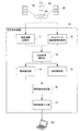
最初に、本実施の形態における障害検知装置の構成について説明する。図1は、本発明の実施の形態における障害検知装置の構成を示すブロック図である。
[Device configuration]
First, the configuration of the failure detection apparatus in the present embodiment will be described. FIG. 1 is a block diagram showing a configuration of a failure detection apparatus according to an embodiment of the present invention.
図1に示す本実施の形態1における障害検知装置10は、ネットワーク20に接続されたサーバ装置30における障害を検知するための装置である。また、各サーバ装置30は、外部からの指示に応じて、アプリケーションプログラム(以下「アプリケーション」と表記する。)を実行するアプリケーションサーバ装置である。なお、図1の例では、3つのサーバ装置30が例示されているが、本実施の形態においてサーバ装置30の数は特に限定されるものではない。
A
図1に示すように、障害検知装置10は、設定情報収集部11と、ネットワーク構成情報収集部12と、静的解析部14と、動的解析部15と、障害発生判定部16とを備えている。このうち、設定情報収集部11は、サーバ装置30から、サーバ装置が実行するアプリケーションの設定情報を収集する。ネットワーク構成情報収集部12は、サーバ装置30から、アプリケーションによる通信の状況を特定するネットワーク構成情報を収集する。
As illustrated in FIG. 1, the
また、静的解析部14は、設定情報収集部11によって収集された設定情報に基づいて静的解析を行い、それによって静的解析情報を抽出する。動的解析部15は、ネットワーク構成情報収集部12によって収集されたネットワーク構成情報に基づいて、動的解析を行い、それによって動的解析情報を抽出する。
In addition, the
障害発生判定部16は、静的解析情報と動的解析情報とを照合して、設定情報に設定されているアプリケーションによる通信と、実行されているアプリケーションによる通信との差異を特定する。そして、障害発生判定部16は、特定した差異にもとづいて、障害が発生しているかどうかを判定する。
The failure
このように、本実施の形態では、アプリケーションの通信に関するコンフィグレーションの解析で得られる静的解析情報と、アプリケーションが動作しているコンピュータの通信パスの接続状態の解析で得られる動的解析情報とが比較される。そして、両者の差異に基づいて、静的解析情報に対応する通信パスが確立されているかどうかが判定され、判定結果に基づいて、アプリケーションの通信パスの障害が検知される。 As described above, in this embodiment, static analysis information obtained by analyzing a configuration related to communication of an application, dynamic analysis information obtained by analyzing a connection state of a communication path of a computer on which the application is operating, and Are compared. Then, based on the difference between the two, it is determined whether or not a communication path corresponding to the static analysis information has been established, and a failure in the communication path of the application is detected based on the determination result.
また、アプリケーションの通信に関するコンフィグレーション(設定情報)は、恒久的な情報ではなく、都度収集される。このため、本実施の形態によれば、従来と異なり、サーバが実行するアプリケーションの設定情報が変更された場合であっても、簡単、且つ、確実に、障害を検知することができる。 Also, the configuration (setting information) related to application communication is not permanent information but is collected each time. For this reason, according to the present embodiment, unlike the conventional case, even when the setting information of the application executed by the server is changed, a failure can be detected easily and reliably.
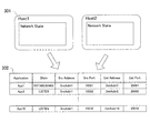
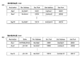
ここで、図1に加えて、図2及び図3を用いて、更に具体的に障害検知装置について説明する。図2は、本実施の形態において収集される設定情報と抽出される静的解析情報との一例を示す図である。図3は、本実施の形態において収集されるネットワーク構成情報と抽出される動的解析情報との一例を示す図である。 Here, in addition to FIG. 1, the failure detection apparatus will be described more specifically with reference to FIGS. FIG. 2 is a diagram illustrating an example of the setting information collected and the extracted static analysis information in the present embodiment. FIG. 3 is a diagram illustrating an example of network configuration information collected and dynamic analysis information extracted in the present embodiment.
まず、図1に示すように、本実施の形態では、障害検知装置10は、更に、設定情報収集部11、ネットワーク構成情報収集部12、静的解析部14、動的解析部15、及び障害発生判定部16に加えて、収集結果通知部13と解析結果出力部17とを備えている。
First, as shown in FIG. 1, in this embodiment, the
収集結果通知部13は、まず、設定情報収集部11から設定情報を取得し、ネットワーク構成情報収集部12からネットワーク構成情報を取得する。そして、収集結果通知部13は、取得した設定情報を静的解析部14に出力し、取得したネットワーク構成情報を動的解析部15に出力する。
The collection
また、本実施の形態では、図2に示すように、設定情報収集部11は、監視対象となるサーバ30毎に、設定情報201を収集する。設定情報201は、サーバ30の数と各サーバで動作するアプリケーションの数とだけ存在する。設定情報201には、例えば、送信元のアドレス(IPアドレス)、ホスト名(サーバ名)、送信元ポート番号といった送信元情報と、宛先のアドレス(IPアドレス)、宛先ポート番号といった接続先情報と、アプリケーション名等のアプリケーション定義情報とが含まれている。
In the present embodiment, as illustrated in FIG. 2, the setting
また、図2に示すように、静的解析部14は、設定情報(Configuration)201から、静的解析情報として、アプリケーション毎に、アプリケーションによる通信に対して予め設定された、送信元アドレス(SrcAddress)、送信元ポート番号(SrcPort)、宛先アドレス(DstAddress)、及び宛先ポート番号(DstPort)を抽出する。静的解析情報は、静的解析結果202として、障害発生判定部16に出力される。
Further, as shown in FIG. 2, the
また、本実施の形態では、図3に示すように、ネットワーク構成情報収集部12は、監視対象となるサーバ30毎に、ネットワーク構成情報301を収集する。ネットワーク構成情報301は、監視対象となるサーバ30の数だけ存在する。ネットワーク構成情報301には、実際に動作しているアプリケーションの接続先情報、例えば、宛先のアドレス(IPアドレス)、ホスト名(サーバ名)、宛先ポート番号が含まれている。
In the present embodiment, as shown in FIG. 3, the network configuration
また、図3に示すように、動的解析部15は、ネットワーク構成情報(Network State)301から、動的解析情報として、アプリケーション毎に、アプリケーションによって実行されている通信の状態(State)と、実際の通信で用いられている、送信元アドレス(SrcAddress)、送信元ポート番号(SrcPort)、宛先アドレス(DstAddress)、及び宛先ポート番号(DstPort)とを抽出する。動的解析情報は、動的解析結果302として、障害発生判定部16に出力される。
As shown in FIG. 3, the
また、障害判定部16は、本実施の形態では、静的解析部14が抽出した静的解析情報202と、動的解析部15が抽出した動的解析情報302とを照合する。そして、障害判定部16は、照合結果により、いずれかのアプリケーションにおいて、静的解析情報は存在するが、動的解析情報は存在しない場合(両者が一致しない場合)、このアプリケーションは正常に動作しておらず設定情報に誤りがあると判定する。
In this embodiment, the
一方、障害判定部16は、照合結果により、いずれかのアプリケーションにおいて、静的解析情報は存在しないが、動的解析情報は存在する場合、想定している設定情報以外でこのアプリケーションによる通信が定義されていると判定する。
On the other hand, according to the collation result, the
また、障害判定部16は、照合結果により、いずれかのアプリケーションにおいて、静的解析情報と動的解析情報との両方が存在し、両方が一致する場合は、このアプリケーションは設定された通りに動作していると判定する。
Further, the
解析結果出力部17は、障害発生判定部16から判定結果を受け取り、受け取った判定結果を、管理者の端末40に送信する。この結果、管理者の端末40の表示画面には、判定結果として、各アプリケーションの状態がグラフィック表示される。
The analysis
[装置動作]
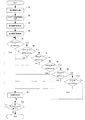
次に、本発明の実施の形態における障害検知装置10動作について図4及び図5を用いて説明する。図4は、本発明の実施の形態における障害検知装置の動作を示すフロー図である。図5は、図4に示す障害発生の判定処理に用いられる静的解析情報及び動的解析情報の一例を示す図である。
[Device operation]
Next, the operation of the
以下の説明においては、適宜図1〜図3を参酌する。また、本実施の形態1では、障害検知装置10を動作させることによって、障害検知方法が実施される。よって、本実施の形態における障害検知方法の説明は、以下の障害検知装置10の動作説明に代える。
In the following description, FIGS. In the first embodiment, the failure detection method is implemented by operating the
図4に示すように、最初に、設定情報収集部11は、各サーバ装置30から、サーバ装置が実行するアプリケーションの設定情報を収集する(ステップA1)。更に、ネットワーク構成情報収集部12は、各サーバ装置30から、アプリケーションによる通信の状況を特定するネットワーク構成情報を収集する(ステップA2)。
As illustrated in FIG. 4, first, the setting
ステップA1及びA2が実行されると、収集結果通知部13が、設定情報収集部11から設定情報を取得し、ネットワーク構成情報収集部12からネットワーク構成情報を取得する。また、収集結果通知部13は、取得した設定情報を静的解析部14に出力し、取得したネットワーク構成情報を動的解析部15に出力する。
When steps A1 and A2 are executed, the collection
次に、静的解析部14は、設定情報201から、静的解析情報を抽出し、これを静的解析結果として障害発生判定部16に出力する(ステップA3)。具体的には、図2に示したように、本実施の形態では、静的解析結果202は、アプリケーションによる通信に対して予め設定された、送信元アドレス(SrcAddress)、送信元ポート番号(SrcPort)、宛先アドレス(DstAddress)、及び宛先ポート番号(DstPort)を含んでいる。
Next, the
次に、動的解析部15は、ネットワーク構成情報301から、動的解析情報を抽出し、これを動的解析結果として障害発生判定部16に出力する(ステップA4)。具体的には、図3に示したように、本実施の形態では、動的解析結果302は、通信の状態(State)と、実際の通信で用いられている、送信元アドレス(SrcAddress)、送信元ポート番号(SrcPort)、宛先アドレス(DstAddress)、及び宛先ポート番号(DstPort)とを含んでいる。
Next, the
ステップA3及びA4が実行されると、障害発生判定部16は、図5に示す静的解析結果(SAR)401と動的解析結果(DAR)402とをインプットデータとして、照合を行い、以下の判定処理(ステップA5〜A10)を実行する。
When steps A3 and A4 are executed, the failure
なお、静的解析結果401は、図2に示した静的解析結果202と同一であり、アプリケーション名、送信元アドレス、送信元ポート番号、宛先アドレス、宛先ポート番号から構成されている。また、動的解析結果402は、図3に示した動的解析結果302と同一であり、アプリケーション名、通信状態、送信元アドレス、送信元ポート番号、宛先アドレス、宛先ポート番号から構成されている。
The
障害発生判定部16は、判定処理として、まず、静的解析結果401に含まれるアプリケーションが、動的解析結果402に含まれるアプリケーションに存在しているかどうかを判定する(ステップA5)。
As the determination process, the failure
ステップA5の判定の結果、存在しない場合は、障害発生判定部16は、設定情報で指定した設定通りにアプリケーションが動作しておらず、障害が発生していると判定する。そして、障害発生判定部16は、解析結果出力部17に、障害を検知したことを出力させる(ステップA11)。
If the result of determination in step A5 is that there is no failure, the failure
その後、障害発生判定部16は、静的解析結果401に含まれる全てのアプリケーションについて処理が終了しているかどうか判定する(ステップA12)。ステップA12の判定の結果、処理が終了していない場合は、再度ステップA5を実行する。ステップA12の判定の結果、全ての処理が終了している場合は、障害検知装置10における処理は一旦終了する。
Thereafter, the failure
一方、ステップA5の判定の結果、存在している場合は、障害発生判定部16は、対象となっているアプリケーションの静的解析結果の送信元アドレスと動的解析結果の送信元アドレスとが一致するかどうかを判定する(ステップA6)。
On the other hand, if it exists as a result of the determination in step A5, the failure
ステップA6の判定の結果、一致しない場合は、障害発生判定部16は、設定情報で指定した設定通りにアプリケーションが動作しておらず、障害が発生していると判定する。そして、障害発生判定部16は、解析結果出力部17によって、ステップA11を実行する。その後、障害発生判定部16は、ステップA12を実行し、処理が終了していない場合は、再度ステップA5を実行する。また、全ての処理が終了している場合は、障害検知装置10における処理は一旦終了する。
As a result of the determination in step A6, if they do not match, the failure
一方、ステップA6の判定の結果、一致している場合は、障害発生判定部16は、対象となっているアプリケーションの静的解析結果の送信元ポート番号と動的解析結果の送信元ポート番号とが一致するかどうかを判定する(ステップA7)。
On the other hand, if they match as a result of the determination in step A6, the failure
ステップA7の判定の結果、一致しない場合は、障害発生判定部16は、設定情報で指定した設定通りにアプリケーションが動作しておらず、障害が発生していると判定する。そして、障害発生判定部16は、解析結果出力部17によって、ステップA11を実行する。その後、障害発生判定部16は、ステップA12を実行し、処理が終了していない場合は、再度ステップA5を実行する。また、全ての処理が終了している場合は、障害検知装置10における処理は一旦終了する。
As a result of the determination in step A7, if they do not match, the failure
一方、ステップA7の判定の結果、一致している場合は、障害発生判定部16は、対象となっているアプリケーションの静的解析結果の宛先アドレスと動的解析結果の宛先アドレスとが一致するかどうかを判定する(ステップA8)。
On the other hand, if they match as a result of the determination in step A7, the failure
ステップA8の判定の結果、一致しない場合は、障害発生判定部16は、設定情報で指定した設定通りにアプリケーションが動作しておらず、障害が発生していると判定する。そして、障害発生判定部16は、解析結果出力部17によって、ステップA11を実行する。その後、障害発生判定部16は、ステップA12を実行し、処理が終了していない場合は、再度ステップA5を実行する。また、全ての処理が終了している場合は、障害検知装置10における処理は一旦終了する。
As a result of the determination in step A8, if they do not match, the failure
一方、ステップA8の判定の結果、一致している場合は、障害発生判定部16は、対象となっているアプリケーションの静的解析結果の宛先ポート番号と動的解析結果の宛先ポート番号とが一致するかどうかを判定する(ステップA9)。
On the other hand, if the result of determination in step A8 matches, the failure
ステップA9の判定の結果、一致しない場合は、障害発生判定部16は、設定情報で指定した設定通りにアプリケーションが動作しておらず、障害が発生していると判定する。そして、障害発生判定部16は、解析結果出力部17によって、ステップA11を実行する。その後、障害発生判定部16は、ステップA12を実行し、処理が終了していない場合は、再度ステップA5を実行する。また、全ての処理が終了している場合は、障害検知装置10における処理は一旦終了する。
As a result of the determination in step A9, if they do not match, the failure
一方、ステップA9の判定の結果、一致している場合は、障害発生判定部16は、対象となっているアプリケーションの通信状態が「ESTABLISHED」となっているかどうかを判定する(ステップA10)。
On the other hand, if they match as a result of the determination in step A9, the failure
ステップA10の判定の結果、「ESTABLISHED」でない場合は、障害発生判定部16は、設定情報で指定した設定通りにアプリケーションが動作しておらず、障害が発生していると判定する。そして、障害発生判定部16は、解析結果出力部17によって、ステップA11を実行する。その後、障害発生判定部16は、ステップA12を実行し、処理が終了していない場合は、再度ステップA5を実行する。また、全ての処理が終了している場合は、障害検知装置10における処理は一旦終了する。
If the result of determination in step A10 is not “ESTABLISHED”, the failure
一方、ステップA10の判定の結果、「ESTABLISHED」である場合は、障害発生判定部16は、対象となっているアプリケーションは、設定情報で指定した設定通りに動作していると判定する。その後、障害発生判定部16は、ステップA12を実行し、処理が終了していない場合は、再度ステップA5を実行する。また、全ての処理が終了している場合は、障害検知装置10における処理は一旦終了する。
On the other hand, if the result of determination in step A10 is “ESTABLISHED”, the failure
このように、ステップA1〜A12の実行により、障害の発生が検知されることになる。また、ステップA1〜A12は、設定された時間毎に、又は管理者からの指示がある度に、繰り返し実行される。 Thus, the occurrence of a failure is detected by executing steps A1 to A12. Steps A1 to A12 are repeatedly executed every set time or whenever there is an instruction from the administrator.
[実施の形態における効果]
以上のように本実施の形態では、設定情報の静的解析から抽出された静的解析情報が、実際の動作状況の解析から抽出された動的解析情報に存在しているかどうかを判定することによって、設定情報の誤りを検出することができる。また、設定情報は、都度収集されている。このため、サーバが実行するアプリケーションの設定情報が変更される環境下にあっても、確実な障害の検知を簡単に行なうことができる。
[Effects of the embodiment]
As described above, in this embodiment, it is determined whether or not the static analysis information extracted from the static analysis of the setting information exists in the dynamic analysis information extracted from the analysis of the actual operation status. Thus, it is possible to detect an error in the setting information. The setting information is collected every time. Therefore, reliable failure detection can be easily performed even in an environment where the setting information of the application executed by the server is changed.
[変形例]
ここで、図6を用いて、本実施の形態における変形例について説明する。変形例では、障害判定部16は、図4に示したステップA5〜A10とは逆に、アプリケーション毎に、動的解析情報に含まれる情報が、静的解析情報に含まれているかどうかを判定する。図6は、本発明の実施の形態における障害検知装置の動作の変形例を示すフロー図である。
[Modification]
Here, a modification example of the present embodiment will be described with reference to FIG. In the modification, the
先ず、ステップB1〜B4が実行される。ステップB1〜B4は、それぞれ、図4に示したステップA1〜A4と同様のステップである。また、ステップB3及びB4が実行されると、障害発生判定部16は、図5に示す静的解析結果(SAR)401と動的解析結果(DAR)402とをインプットデータとして、照合を行い、以下の判定処理(ステップB5〜B10)を実行する。
First, steps B1 to B4 are executed. Steps B1 to B4 are the same as steps A1 to A4 shown in FIG. When Steps B3 and B4 are executed, the failure
障害発生判定部16は、判定処理として、まず、動的解析結果402に含まれるアプリケーションが、静的解析結果401に含まれるアプリケーションに存在しているかどうかを判定する(ステップB5)。
As the determination process, the failure
ステップB5の判定の結果、存在しない場合は、障害発生判定部16は、設定情報で設定されていない想定外の接続がされており、障害が発生していると判定する。そして、障害発生判定部16は、解析結果出力部17に、障害を検知したことを出力させる(ステップB11)。ステップB11は、図4に示したステップA11と同様のステップである。
As a result of the determination in step B5, when there is no failure, the failure
その後、障害発生判定部16は、動的解析結果501に含まれる全てのアプリケーションについて処理が終了しているかどうか判定する(ステップB12)。ステップB12の判定の結果、処理が終了していない場合は、再度ステップB5を実行する。ステップB12の判定の結果、全ての処理が終了している場合は、障害検知装置10における処理は一旦終了する。
Thereafter, the failure
一方、ステップB5の判定の結果、存在している場合は、障害発生判定部16は、対象となっているアプリケーションの動的解析結果の送信元アドレスと静的解析結果の送信元アドレスとが一致するかどうかを判定する(ステップB6)。
On the other hand, if it exists as a result of the determination in step B5, the failure
ステップB6の判定の結果、一致しない場合は、障害発生判定部16は、設定情報で設定されていない想定外の接続がされており、障害が発生していると判定する。そして、障害発生判定部16は、解析結果出力部17によって、ステップB11を実行する。その後、障害発生判定部16は、ステップB12を実行し、処理が終了していない場合は、再度ステップB5を実行する。また、全ての処理が終了している場合は、障害検知装置10における処理は一旦終了する。
As a result of the determination in step B6, if they do not match, the failure
一方、ステップB6の判定の結果、一致している場合は、障害発生判定部16は、対象となっているアプリケーションの動的解析結果の送信元ポート番号と静的解析結果の送信元ポート番号とが一致するかどうかを判定する(ステップB7)。
On the other hand, if they match as a result of the determination in step B6, the failure
ステップB7の判定の結果、一致しない場合は、障害発生判定部16は、設定情報で設定されていない想定外の接続がされており、障害が発生していると判定する。そして、障害発生判定部16は、解析結果出力部17によって、ステップB11を実行する。その後、障害発生判定部16は、ステップB12を実行し、処理が終了していない場合は、再度ステップB5を実行する。また、全ての処理が終了している場合は、障害検知装置10における処理は一旦終了する。
As a result of the determination in step B7, if they do not match, the failure
一方、ステップB7の判定の結果、一致している場合は、障害発生判定部16は、対象となっているアプリケーションの動的解析結果の宛先アドレスと静的解析結果の宛先アドレスとが一致するかどうかを判定する(ステップB8)。
On the other hand, if they match as a result of the determination in step B7, the failure
ステップB8の判定の結果、一致しない場合は、障害発生判定部16は、設定情報で設定されていない想定外の接続がされており、障害が発生していると判定する。そして、障害発生判定部16は、解析結果出力部17によって、ステップB11を実行する。その後、障害発生判定部16は、ステップB12を実行し、処理が終了していない場合は、再度ステップB5を実行する。また、全ての処理が終了している場合は、障害検知装置10における処理は一旦終了する。
As a result of the determination in step B8, if they do not match, the failure
一方、ステップB8の判定の結果、一致している場合は、障害発生判定部16は、対象となっているアプリケーションの動的解析結果の宛先ポート番号と静的解析結果の宛先ポート番号とが一致するかどうかを判定する(ステップB9)。
On the other hand, if the result of determination in step B8 matches, the failure
ステップB9の判定の結果、一致しない場合は、障害発生判定部16は、設定情報で設定されていない想定外の接続がされており、障害が発生していると判定する。そして、障害発生判定部16は、解析結果出力部17によって、ステップB11を実行する。その後、障害発生判定部16は、ステップB12を実行し、処理が終了していない場合は、再度ステップB5を実行する。また、全ての処理が終了している場合は、障害検知装置10における処理は一旦終了する。
As a result of the determination in step B9, if they do not match, the failure
一方、ステップB9の判定の結果、一致している場合は、障害発生判定部16は、対象となっているアプリケーションの通信状態が「ESTABLISHED」となっているかどうかを判定する(ステップB10)。
On the other hand, if they match as a result of the determination in step B9, the failure
ステップB10の判定の結果、「ESTABLISHED」でない場合は、障害発生判定部16は、設定情報で指定した設定通りにアプリケーションが動作しておらず、障害が発生していると判定する。そして、障害発生判定部16は、解析結果出力部17によって、ステップB11を実行する。その後、障害発生判定部16は、ステップB12を実行し、処理が終了していない場合は、再度ステップB5を実行する。また、全ての処理が終了している場合は、障害検知装置10における処理は一旦終了する。
If the result of determination in step B10 is not “ESTABLISHED”, the failure
一方、ステップB10の判定の結果、「ESTABLISHED」である場合は、障害発生判定部16は、対象となっているアプリケーションは、設定情報で指定した設定通りに動作していると判定する。その後、障害発生判定部16は、ステップB12を実行し、処理が終了していない場合は、再度ステップB5を実行する。また、全ての処理が終了している場合は、障害検知装置10における処理は一旦終了する。
On the other hand, if the result of determination in step B10 is “ESTABLISHED”, the failure
このように、変形例では、ステップB1〜B12の実行により、障害の発生が検知されることになる。また、ステップB1〜B12も、設定された時間毎に、又は管理者からの指示がある度に、繰り返し実行される。 Thus, in the modification, the occurrence of a failure is detected by executing Steps B1 to B12. Steps B1 to B12 are also repeatedly executed every set time or whenever there is an instruction from the administrator.
また、変形例では、動的解析結果(DAR)402が、静的解析結果(SAR)401に存在しているかどうかをチェックしている。つまり、実際の動作状況を解析した動的解析情報が、設定情報に基づく静的解析情報に存在しないことを検知できるため、設定情報に設定されていない想定外のアプリケーション間の接続を検出する事ができる。 In the modified example, it is checked whether the dynamic analysis result (DAR) 402 exists in the static analysis result (SAR) 401. In other words, since it is possible to detect that the dynamic analysis information obtained by analyzing the actual operation status does not exist in the static analysis information based on the setting information, it is possible to detect connections between unexpected applications that are not set in the setting information. Can do.
[プログラム] [program]
本実施の形態におけるプログラムは、コンピュータに、図4に示すステップA1〜A12又は図6に示すステップB1〜B12を実行させるプログラムであれば良い。このプログラムをコンピュータにインストールし、実行することによって、本実施の形態における障害検知装置10と障害検知方法とを実現することができる。この場合、コンピュータのCPU(Central Processing Unit)は、設定情報収集部11、ネットワーク構成情報収集部12、収集結果通知部13、静的解析部14、動的解析部15、障害発生判定部16、及び解析結果出力部17として機能し、処理を行なう。
The program in the present embodiment may be a program that causes a computer to execute steps A1 to A12 shown in FIG. 4 or steps B1 to B12 shown in FIG. By installing and executing this program on a computer, the
ここで、本実施の形態におけるプログラムを実行することによって、障害検知装置を実現するコンピュータについて図7を用いて説明する。図7は、本発明の実施の形態における障害検知装置を実現するコンピュータの一例を示すブロック図である。 Here, a computer that realizes the failure detection apparatus by executing the program according to the present embodiment will be described with reference to FIG. FIG. 7 is a block diagram illustrating an example of a computer that implements the failure detection apparatus according to the embodiment of the present invention.
図7に示すように、コンピュータ110は、CPU111と、メインメモリ112と、記憶装置113と、入力インターフェイス114と、表示コントローラ115と、データリーダ/ライタ116と、通信インターフェイス117とを備える。これらの各部は、バス121を介して、互いにデータ通信可能に接続される。
As shown in FIG. 7, the
CPU111は、記憶装置113に格納された、本実施の形態におけるプログラム(コード)をメインメモリ112に展開し、これらを所定順序で実行することにより、各種の演算を実施する。メインメモリ112は、典型的には、DRAM(Dynamic Random Access Memory)等の揮発性の記憶装置である。また、本実施の形態におけるプログラムは、コンピュータ読み取り可能な記録媒体120に格納された状態で提供される。なお、本実施の形態におけるプログラムは、通信インターフェイス117を介して接続されたインターネット上で流通するものであっても良い。
The
また、記憶装置113の具体例としては、ハードディスクの他、フラッシュメモリ等の半導体記憶装置が挙げられる。入力インターフェイス114は、CPU111と、キーボード及びマウスといった入力機器118との間のデータ伝送を仲介する。表示コントローラ115は、ディスプレイ装置119と接続され、ディスプレイ装置119での表示を制御する。
Specific examples of the
データリーダ/ライタ116は、CPU111と記録媒体120との間のデータ伝送を仲介し、記録媒体120からのプログラムの読み出し、及びコンピュータ110における処理結果の記録媒体120への書き込みを実行する。通信インターフェイス117は、CPU111と、他のコンピュータとの間のデータ伝送を仲介する。
The data reader /
また、記録媒体120の具体例としては、CF(Compact Flash(登録商標))及びSD(Secure Digital)等の汎用的な半導体記憶デバイス、フレキシブルディスク(Flexible Disk)等の磁気記憶媒体、又はCD−ROM(Compact Disk Read Only Memory)などの光学記憶媒体が挙げられる。
Specific examples of the
以上のように、本発明によれば、サーバが実行するアプリケーションの設定情報が変更された場合であっても、簡単、且つ、確実に、障害を検知することができる。本発明は、資産管理システム、監視システム、セキュリティシステムといったコンピュータシステムに有用である。 As described above, according to the present invention, a failure can be detected easily and reliably even when the setting information of an application executed by the server is changed. The present invention is useful for computer systems such as asset management systems, monitoring systems, and security systems.
10 障害検知装置
11 設定情報収集部
12 ネットワーク構成情報収集部
13 収集結果通知部
14 静的解析部
15 動的解析部
16 障害発生判定部
17 解析結果出力部
20 ネットワーク
30 サーバ
40 端末
110 コンピュータ
111 CPU
112 メインメモリ
113 記憶装置
114 入力インターフェイス
115 表示コントローラ
116 データリーダ/ライタ
117 通信インターフェイス
118 入力機器
119 ディスプレイ装置
120 記録媒体
121 バス
DESCRIPTION OF
112
Claims (9)
設定された時間毎、又は外部からの指示がある度に、前記サーバ装置から、前記サーバ装置が実行するアプリケーションプログラムの設定情報を収集する、設定情報収集部と、
前記サーバ装置から、前記アプリケーションプログラムによる通信の状況を特定するネットワーク構成情報を収集する、ネットワーク構成情報収集部と、
収集された前記設定情報に基づいて静的解析を行い、それによって静的解析情報を抽出する、静的解析部と、
収集された前記ネットワーク構成情報に基づいて動的解析を行い、それによって動的解析情報を抽出する、動的解析部と、
前記静的解析情報と前記動的解析情報とを照合して、前記設定情報に設定されている前記アプリケーションプログラムによる通信と、実行されている前記アプリケーションプログラムによる通信との差異を特定し、特定した差異にもとづいて、障害が発生しているかどうかを判定する、障害発生判定部と、
を備えていることを特徴とする障害検知装置。 A device for detecting a failure in a server device connected to a network,
A setting information collection unit that collects setting information of an application program executed by the server device from the server device every set time or whenever there is an instruction from the outside ;
A network configuration information collecting unit that collects network configuration information for specifying a communication status by the application program from the server device;
A static analysis unit that performs static analysis based on the collected setting information and thereby extracts static analysis information; and
A dynamic analysis unit that performs dynamic analysis based on the collected network configuration information and thereby extracts dynamic analysis information; and
The static analysis information and the dynamic analysis information are collated, and the difference between the communication by the application program set in the setting information and the communication by the application program being executed is specified and specified. A failure occurrence determination unit that determines whether a failure has occurred based on the difference; and
A failure detection device comprising:
前記動的解析部が、前記動的解析情報として、前記アプリケーションプログラム毎に、当該アプリケーションプログラムによって実行されている通信の状態、更には、当該通信で用いられている、送信元アドレス、送信元ポート番号、宛先アドレス、及び宛先ポート番号を抽出する、請求項1に記載の障害検知装置。 The static analysis unit sets, as the static analysis information, for each application program, a transmission source address, a transmission source port number, a destination address, and a destination port number preset for communication by the application program. Extract and
The dynamic analysis unit, as the dynamic analysis information, for each application program, the state of communication being executed by the application program, and further, a source address, a source port used in the communication The failure detection apparatus according to claim 1, wherein a number, a destination address, and a destination port number are extracted.
請求項2に記載の障害検知装置。 In the failure occurrence determination unit, the static analysis information and the dynamic analysis information match in all of the application program, the transmission source address, the transmission source port number, the destination address, and the destination port number, and communication is performed. If established, it is determined that no failure has occurred; otherwise, it is determined that a failure has occurred.
The failure detection apparatus according to claim 2.
(a)設定された時間毎、又は外部からの指示がある度に、前記サーバ装置から、前記サーバ装置が実行するアプリケーションプログラムの設定情報を収集する、ステップと、
(b)前記サーバ装置から、前記アプリケーションプログラムによる通信の状況を特定するネットワーク構成情報を収集する、ステップと、
(c)収集された前記設定情報に基づいて静的解析を行い、それによって静的解析情報を抽出する、ステップと、
(d)収集された前記ネットワーク構成情報に基づいて動的解析を行い、それによって動的解析情報を抽出する、ステップと、
(e)前記静的解析情報と前記動的解析情報とを照合して、前記設定情報に設定されている前記アプリケーションプログラムによる通信と、実行されている前記アプリケーションプログラムによる通信との差異を特定し、特定した差異にもとづいて、障害が発生しているかどうかを判定する、ステップと、
を有することを特徴とする障害検知方法。 A method for detecting a failure in a server device connected to a network,
(A) collecting setting information of an application program executed by the server device from the server device every set time or whenever there is an external instruction ;
(B) collecting network configuration information for identifying the status of communication by the application program from the server device;
(C) performing a static analysis based on the collected setting information, thereby extracting the static analysis information;
(D) performing a dynamic analysis based on the collected network configuration information, thereby extracting the dynamic analysis information;
(E) The static analysis information and the dynamic analysis information are collated to identify a difference between communication by the application program set in the setting information and communication by the application program being executed. Determining whether a failure has occurred based on the identified differences;
A failure detection method characterized by comprising:
前記(d)のステップにおいて、前記動的解析情報として、前記アプリケーションプログラム毎に、当該アプリケーションプログラムによって実行されている通信の状態、更には、当該通信で用いられている、送信元アドレス、送信元ポート番号、宛先アドレス、及び宛先ポート番号を抽出する、請求項4に記載の障害検知方法。 In the step (c), as the static analysis information, a transmission source address, a transmission source port number, a destination address, and a destination port number preset for communication by the application program for each application program. Extract
In the step (d), as the dynamic analysis information, for each application program, the state of communication executed by the application program, and further, a transmission source address and a transmission source used in the communication The failure detection method according to claim 4, wherein a port number, a destination address, and a destination port number are extracted.
請求項5に記載の障害検知方法。 In the step (e), the static analysis information and the dynamic analysis information match in all of the application program, source address, source port number, destination address, and destination port number, and communication If it is established, it is determined that no failure has occurred. Otherwise, it is determined that a failure has occurred.
The failure detection method according to claim 5.
前記コンピュータに、
(a)設定された時間毎、又は外部からの指示がある度に、前記サーバ装置から、前記サーバ装置が実行するアプリケーションプログラムの設定情報を収集する、ステップと、
(b)前記サーバ装置から、前記アプリケーションプログラムによる通信の状況を特定するネットワーク構成情報を収集する、ステップと、
(c)収集された前記設定情報に基づいて静的解析を行い、それによって静的解析情報を抽出する、ステップと、
(d)収集された前記ネットワーク構成情報に基づいて動的解析を行い、それによって動的解析情報を抽出する、ステップと、
(e)前記静的解析情報と前記動的解析情報とを照合して、前記設定情報に設定されている前記アプリケーションプログラムによる通信と、実行されている前記アプリケーションプログラムによる通信との差異を特定し、特定した差異にもとづいて、障害が発生しているかどうかを判定する、ステップと、
を実行させるプログラム。 A program for detecting a failure in a server device connected to a network by a computer,
In the computer,
(A) collecting setting information of an application program executed by the server device from the server device every set time or whenever there is an external instruction ;
(B) collecting network configuration information for identifying the status of communication by the application program from the server device;
(C) performing a static analysis based on the collected setting information, thereby extracting the static analysis information;
(D) performing a dynamic analysis based on the collected network configuration information, thereby extracting the dynamic analysis information;
(E) The static analysis information and the dynamic analysis information are collated to identify a difference between communication by the application program set in the setting information and communication by the application program being executed. Determining whether a failure has occurred based on the identified differences;
A program that executes
前記(d)のステップにおいて、前記動的解析情報として、前記アプリケーションプログラム毎に、当該アプリケーションプログラムによって実行されている通信の状態、更には、当該通信で用いられている、送信元アドレス、送信元ポート番号、宛先アドレス、及び宛先ポート番号を抽出する、請求項7に記載のプログラム。 In the step (c), as the static analysis information, a transmission source address, a transmission source port number, a destination address, and a destination port number preset for communication by the application program for each application program. Extract
In the step (d), as the dynamic analysis information, for each application program, the state of communication executed by the application program, and further, a transmission source address and a transmission source used in the communication The program according to claim 7, wherein the program extracts a port number, a destination address, and a destination port number.
請求項8に記載のプログラム。 In the step (e), the static analysis information and the dynamic analysis information match in all of the application program, source address, source port number, destination address, and destination port number, and communication If it is established, it is determined that no failure has occurred. Otherwise, it is determined that a failure has occurred.
The program according to claim 8.
Priority Applications (1)
| Application Number | Priority Date | Filing Date | Title |
|---|---|---|---|
| JP2012059051A JP5679347B2 (en) | 2012-03-15 | 2012-03-15 | Failure detection device, failure detection method, and program |
Applications Claiming Priority (1)
| Application Number | Priority Date | Filing Date | Title |
|---|---|---|---|
| JP2012059051A JP5679347B2 (en) | 2012-03-15 | 2012-03-15 | Failure detection device, failure detection method, and program |
Publications (2)
| Publication Number | Publication Date |
|---|---|
| JP2013197601A JP2013197601A (en) | 2013-09-30 |
| JP5679347B2 true JP5679347B2 (en) | 2015-03-04 |
Family
ID=49396105
Family Applications (1)
| Application Number | Title | Priority Date | Filing Date |
|---|---|---|---|
| JP2012059051A Active JP5679347B2 (en) | 2012-03-15 | 2012-03-15 | Failure detection device, failure detection method, and program |
Country Status (1)
| Country | Link |
|---|---|
| JP (1) | JP5679347B2 (en) |
Families Citing this family (2)
| Publication number | Priority date | Publication date | Assignee | Title |
|---|---|---|---|---|
| JP6482284B2 (en) * | 2015-01-15 | 2019-03-13 | キヤノン株式会社 | Information processing apparatus, policy management apparatus, security policy management method, computer program |
| CN117077040B (en) * | 2023-09-04 | 2024-02-23 | 武汉蓝海科创技术有限公司 | Large-scale complex equipment fault diagnosis and prediction system based on machine learning |
Family Cites Families (2)
| Publication number | Priority date | Publication date | Assignee | Title |
|---|---|---|---|---|
| JP3621010B2 (en) * | 1999-12-14 | 2005-02-16 | 日本電信電話株式会社 | Network management method and system apparatus |
| JP4376270B2 (en) * | 2007-01-24 | 2009-12-02 | 富士通株式会社 | Network configuration verification program, network configuration verification method, and network configuration verification device |
-
2012
- 2012-03-15 JP JP2012059051A patent/JP5679347B2/en active Active
Also Published As
| Publication number | Publication date |
|---|---|
| JP2013197601A (en) | 2013-09-30 |
Similar Documents
| Publication | Publication Date | Title |
|---|---|---|
| JP5684946B2 (en) | Method and system for supporting analysis of root cause of event | |
| CN113489713B (en) | Network attack detection method, device, equipment and storage medium | |
| JP6111441B2 (en) | Tracking application usage in computing environments | |
| US9450980B2 (en) | Automatic malignant code collecting system | |
| US7398511B2 (en) | System and method for providing a health model for software | |
| US20130111018A1 (en) | Passive monitoring of virtual systems using agent-less, offline indexing | |
| JP6282217B2 (en) | Anti-malware system and anti-malware method | |
| WO2006117833A1 (en) | Monitoring simulating device, method, and program | |
| US11314610B2 (en) | Auto-recovery for software systems | |
| WO2019026310A1 (en) | Information processing device, information processing method, and information processing program | |
| JP5936798B2 (en) | Log analysis device, unauthorized access audit system, log analysis program, and log analysis method | |
| CN112818307A (en) | User operation processing method, system, device and computer readable storage medium | |
| CN108804914B (en) | Abnormal data detection method and device | |
| CN111183620A (en) | Intrusion investigation | |
| CN105760761A (en) | Software behavior analyzing method and device | |
| EP3011454A1 (en) | Generating a fingerprint representing a response of an application to a simulation of a fault of an external service | |
| JP2008158889A (en) | Trouble factor detection program, trouble factor detection method and trouble factor detector | |
| KR101619691B1 (en) | Method and system for analyzing program error | |
| JP4913353B2 (en) | Software operation modeling device and software operation monitoring device | |
| JP5679347B2 (en) | Failure detection device, failure detection method, and program | |
| JP2017211806A (en) | Communication monitoring method, security management system, and program | |
| JP6142878B2 (en) | Information system performance evaluation apparatus, method and program | |
| JP5386015B1 (en) | Bug detection apparatus and bug detection method | |
| US20150154498A1 (en) | Methods for identifying silent failures in an application and devices thereof | |
| JP7302223B2 (en) | Script detection device, method and program |
Legal Events
| Date | Code | Title | Description |
|---|---|---|---|
| A621 | Written request for application examination |
Free format text: JAPANESE INTERMEDIATE CODE: A621 Effective date: 20130711 |
|
| A977 | Report on retrieval |
Free format text: JAPANESE INTERMEDIATE CODE: A971007 Effective date: 20140228 |
|
| A131 | Notification of reasons for refusal |
Free format text: JAPANESE INTERMEDIATE CODE: A131 Effective date: 20140409 |
|
| A521 | Written amendment |
Free format text: JAPANESE INTERMEDIATE CODE: A523 Effective date: 20140604 |
|
| A711 | Notification of change in applicant |
Free format text: JAPANESE INTERMEDIATE CODE: A712 Effective date: 20140609 |
|
| TRDD | Decision of grant or rejection written | ||
| A01 | Written decision to grant a patent or to grant a registration (utility model) |
Free format text: JAPANESE INTERMEDIATE CODE: A01 Effective date: 20141209 |
|
| A61 | First payment of annual fees (during grant procedure) |
Free format text: JAPANESE INTERMEDIATE CODE: A61 Effective date: 20141225 |
|
| R150 | Certificate of patent or registration of utility model |
Ref document number: 5679347 Country of ref document: JP Free format text: JAPANESE INTERMEDIATE CODE: R150 |