JP5677423B2 - Detection of contact on a curved surface - Google Patents
Detection of contact on a curved surface Download PDFInfo
- Publication number
- JP5677423B2 JP5677423B2 JP2012516079A JP2012516079A JP5677423B2 JP 5677423 B2 JP5677423 B2 JP 5677423B2 JP 2012516079 A JP2012516079 A JP 2012516079A JP 2012516079 A JP2012516079 A JP 2012516079A JP 5677423 B2 JP5677423 B2 JP 5677423B2
- Authority
- JP
- Japan
- Prior art keywords
- sensor
- touch
- mouse
- sensor elements
- forming
- Prior art date
- Legal status (The legal status is an assumption and is not a legal conclusion. Google has not performed a legal analysis and makes no representation as to the accuracy of the status listed.)
- Active
Links
- 238000001514 detection method Methods 0.000 title description 13
- 238000000034 method Methods 0.000 claims description 81
- 239000000758 substrate Substances 0.000 claims description 49
- 238000004519 manufacturing process Methods 0.000 claims description 15
- 241000699666 Mus <mouse, genus> Species 0.000 description 179
- 230000006870 function Effects 0.000 description 43
- 238000005259 measurement Methods 0.000 description 34
- 239000000976 ink Substances 0.000 description 29
- 239000000463 material Substances 0.000 description 12
- 230000008569 process Effects 0.000 description 12
- 230000008859 change Effects 0.000 description 9
- 238000007639 printing Methods 0.000 description 9
- 239000010410 layer Substances 0.000 description 8
- 238000010586 diagram Methods 0.000 description 6
- 239000011888 foil Substances 0.000 description 6
- 238000002847 impedance measurement Methods 0.000 description 6
- 230000007246 mechanism Effects 0.000 description 6
- 241000699670 Mus sp. Species 0.000 description 5
- BQCADISMDOOEFD-UHFFFAOYSA-N Silver Chemical compound [Ag] BQCADISMDOOEFD-UHFFFAOYSA-N 0.000 description 5
- 230000009471 action Effects 0.000 description 5
- 230000008901 benefit Effects 0.000 description 5
- 238000013461 design Methods 0.000 description 5
- 230000003993 interaction Effects 0.000 description 5
- 238000000465 moulding Methods 0.000 description 5
- 229920000642 polymer Polymers 0.000 description 5
- 229910052709 silver Inorganic materials 0.000 description 5
- 239000004332 silver Substances 0.000 description 5
- 239000004020 conductor Substances 0.000 description 4
- 238000003825 pressing Methods 0.000 description 4
- 230000004044 response Effects 0.000 description 4
- 230000008713 feedback mechanism Effects 0.000 description 3
- 239000011810 insulating material Substances 0.000 description 3
- 230000035945 sensitivity Effects 0.000 description 3
- PPBRXRYQALVLMV-UHFFFAOYSA-N Styrene Chemical compound C=CC1=CC=CC=C1 PPBRXRYQALVLMV-UHFFFAOYSA-N 0.000 description 2
- 238000013459 approach Methods 0.000 description 2
- 238000005452 bending Methods 0.000 description 2
- 238000004891 communication Methods 0.000 description 2
- 238000005520 cutting process Methods 0.000 description 2
- 238000000151 deposition Methods 0.000 description 2
- 239000003989 dielectric material Substances 0.000 description 2
- 230000000694 effects Effects 0.000 description 2
- 239000011521 glass Substances 0.000 description 2
- AMGQUBHHOARCQH-UHFFFAOYSA-N indium;oxotin Chemical group [In].[Sn]=O AMGQUBHHOARCQH-UHFFFAOYSA-N 0.000 description 2
- 239000004973 liquid crystal related substance Substances 0.000 description 2
- 238000013507 mapping Methods 0.000 description 2
- 238000000691 measurement method Methods 0.000 description 2
- 238000007649 pad printing Methods 0.000 description 2
- 230000010363 phase shift Effects 0.000 description 2
- 229920000728 polyester Polymers 0.000 description 2
- 229920000139 polyethylene terephthalate Polymers 0.000 description 2
- 239000005020 polyethylene terephthalate Substances 0.000 description 2
- 239000011241 protective layer Substances 0.000 description 2
- 238000012546 transfer Methods 0.000 description 2
- 238000007666 vacuum forming Methods 0.000 description 2
- NLHHRLWOUZZQLW-UHFFFAOYSA-N Acrylonitrile Chemical compound C=CC#N NLHHRLWOUZZQLW-UHFFFAOYSA-N 0.000 description 1
- OKTJSMMVPCPJKN-UHFFFAOYSA-N Carbon Chemical compound [C] OKTJSMMVPCPJKN-UHFFFAOYSA-N 0.000 description 1
- 241000283070 Equus zebra Species 0.000 description 1
- 230000004913 activation Effects 0.000 description 1
- 239000000853 adhesive Substances 0.000 description 1
- 230000001070 adhesive effect Effects 0.000 description 1
- 239000013590 bulk material Substances 0.000 description 1
- 229910052799 carbon Inorganic materials 0.000 description 1
- 238000005266 casting Methods 0.000 description 1
- 238000006243 chemical reaction Methods 0.000 description 1
- 239000011248 coating agent Substances 0.000 description 1
- 238000000576 coating method Methods 0.000 description 1
- 230000006835 compression Effects 0.000 description 1
- 238000007906 compression Methods 0.000 description 1
- 229920001940 conductive polymer Polymers 0.000 description 1
- 230000008878 coupling Effects 0.000 description 1
- 238000010168 coupling process Methods 0.000 description 1
- 238000005859 coupling reaction Methods 0.000 description 1
- 238000005034 decoration Methods 0.000 description 1
- 230000007423 decrease Effects 0.000 description 1
- 230000008021 deposition Effects 0.000 description 1
- 229910003460 diamond Inorganic materials 0.000 description 1
- 239000010432 diamond Substances 0.000 description 1
- 230000005057 finger movement Effects 0.000 description 1
- 229920002457 flexible plastic Polymers 0.000 description 1
- 230000000977 initiatory effect Effects 0.000 description 1
- 238000007641 inkjet printing Methods 0.000 description 1
- 238000003780 insertion Methods 0.000 description 1
- 230000037431 insertion Effects 0.000 description 1
- 238000009434 installation Methods 0.000 description 1
- 230000002452 interceptive effect Effects 0.000 description 1
- 238000010030 laminating Methods 0.000 description 1
- 239000011159 matrix material Substances 0.000 description 1
- 229910052751 metal Inorganic materials 0.000 description 1
- 239000002184 metal Substances 0.000 description 1
- VNWKTOKETHGBQD-UHFFFAOYSA-N methane Chemical compound C VNWKTOKETHGBQD-UHFFFAOYSA-N 0.000 description 1
- 238000004091 panning Methods 0.000 description 1
- 239000004033 plastic Substances 0.000 description 1
- 229920003023 plastic Polymers 0.000 description 1
- 229920000515 polycarbonate Polymers 0.000 description 1
- 239000004417 polycarbonate Substances 0.000 description 1
- -1 polyethylene terephthalate Polymers 0.000 description 1
- 230000036544 posture Effects 0.000 description 1
- 238000002360 preparation method Methods 0.000 description 1
- 238000012545 processing Methods 0.000 description 1
- 238000005070 sampling Methods 0.000 description 1
- 238000007650 screen-printing Methods 0.000 description 1
- 239000002356 single layer Substances 0.000 description 1
- 230000000007 visual effect Effects 0.000 description 1
Images


Classifications
-
- G—PHYSICS
- G06—COMPUTING; CALCULATING OR COUNTING
- G06F—ELECTRIC DIGITAL DATA PROCESSING
- G06F3/00—Input arrangements for transferring data to be processed into a form capable of being handled by the computer; Output arrangements for transferring data from processing unit to output unit, e.g. interface arrangements
- G06F3/01—Input arrangements or combined input and output arrangements for interaction between user and computer
- G06F3/03—Arrangements for converting the position or the displacement of a member into a coded form
- G06F3/033—Pointing devices displaced or positioned by the user, e.g. mice, trackballs, pens or joysticks; Accessories therefor
- G06F3/0354—Pointing devices displaced or positioned by the user, e.g. mice, trackballs, pens or joysticks; Accessories therefor with detection of 2D relative movements between the device, or an operating part thereof, and a plane or surface, e.g. 2D mice, trackballs, pens or pucks
- G06F3/03543—Mice or pucks
-
- G—PHYSICS
- G06—COMPUTING; CALCULATING OR COUNTING
- G06F—ELECTRIC DIGITAL DATA PROCESSING
- G06F3/00—Input arrangements for transferring data to be processed into a form capable of being handled by the computer; Output arrangements for transferring data from processing unit to output unit, e.g. interface arrangements
- G06F3/01—Input arrangements or combined input and output arrangements for interaction between user and computer
- G06F3/02—Input arrangements using manually operated switches, e.g. using keyboards or dials
- G06F3/0202—Constructional details or processes of manufacture of the input device
-
- G—PHYSICS
- G06—COMPUTING; CALCULATING OR COUNTING
- G06F—ELECTRIC DIGITAL DATA PROCESSING
- G06F3/00—Input arrangements for transferring data to be processed into a form capable of being handled by the computer; Output arrangements for transferring data from processing unit to output unit, e.g. interface arrangements
- G06F3/01—Input arrangements or combined input and output arrangements for interaction between user and computer
- G06F3/03—Arrangements for converting the position or the displacement of a member into a coded form
- G06F3/033—Pointing devices displaced or positioned by the user, e.g. mice, trackballs, pens or joysticks; Accessories therefor
- G06F3/0354—Pointing devices displaced or positioned by the user, e.g. mice, trackballs, pens or joysticks; Accessories therefor with detection of 2D relative movements between the device, or an operating part thereof, and a plane or surface, e.g. 2D mice, trackballs, pens or pucks
- G06F3/03541—Mouse/trackball convertible devices, in which the same ball is used to track the 2D relative movement
-
- G—PHYSICS
- G06—COMPUTING; CALCULATING OR COUNTING
- G06F—ELECTRIC DIGITAL DATA PROCESSING
- G06F3/00—Input arrangements for transferring data to be processed into a form capable of being handled by the computer; Output arrangements for transferring data from processing unit to output unit, e.g. interface arrangements
- G06F3/01—Input arrangements or combined input and output arrangements for interaction between user and computer
- G06F3/03—Arrangements for converting the position or the displacement of a member into a coded form
- G06F3/033—Pointing devices displaced or positioned by the user, e.g. mice, trackballs, pens or joysticks; Accessories therefor
- G06F3/038—Control and interface arrangements therefor, e.g. drivers or device-embedded control circuitry
- G06F3/0383—Signal control means within the pointing device
-
- G—PHYSICS
- G06—COMPUTING; CALCULATING OR COUNTING
- G06F—ELECTRIC DIGITAL DATA PROCESSING
- G06F3/00—Input arrangements for transferring data to be processed into a form capable of being handled by the computer; Output arrangements for transferring data from processing unit to output unit, e.g. interface arrangements
- G06F3/01—Input arrangements or combined input and output arrangements for interaction between user and computer
- G06F3/03—Arrangements for converting the position or the displacement of a member into a coded form
- G06F3/041—Digitisers, e.g. for touch screens or touch pads, characterised by the transducing means
- G06F3/0412—Digitisers structurally integrated in a display
-
- G—PHYSICS
- G06—COMPUTING; CALCULATING OR COUNTING
- G06F—ELECTRIC DIGITAL DATA PROCESSING
- G06F3/00—Input arrangements for transferring data to be processed into a form capable of being handled by the computer; Output arrangements for transferring data from processing unit to output unit, e.g. interface arrangements
- G06F3/01—Input arrangements or combined input and output arrangements for interaction between user and computer
- G06F3/03—Arrangements for converting the position or the displacement of a member into a coded form
- G06F3/041—Digitisers, e.g. for touch screens or touch pads, characterised by the transducing means
- G06F3/0414—Digitisers, e.g. for touch screens or touch pads, characterised by the transducing means using force sensing means to determine a position
-
- G—PHYSICS
- G06—COMPUTING; CALCULATING OR COUNTING
- G06F—ELECTRIC DIGITAL DATA PROCESSING
- G06F3/00—Input arrangements for transferring data to be processed into a form capable of being handled by the computer; Output arrangements for transferring data from processing unit to output unit, e.g. interface arrangements
- G06F3/01—Input arrangements or combined input and output arrangements for interaction between user and computer
- G06F3/03—Arrangements for converting the position or the displacement of a member into a coded form
- G06F3/041—Digitisers, e.g. for touch screens or touch pads, characterised by the transducing means
- G06F3/044—Digitisers, e.g. for touch screens or touch pads, characterised by the transducing means by capacitive means
- G06F3/0443—Digitisers, e.g. for touch screens or touch pads, characterised by the transducing means by capacitive means using a single layer of sensing electrodes
-
- G—PHYSICS
- G06—COMPUTING; CALCULATING OR COUNTING
- G06F—ELECTRIC DIGITAL DATA PROCESSING
- G06F3/00—Input arrangements for transferring data to be processed into a form capable of being handled by the computer; Output arrangements for transferring data from processing unit to output unit, e.g. interface arrangements
- G06F3/01—Input arrangements or combined input and output arrangements for interaction between user and computer
- G06F3/03—Arrangements for converting the position or the displacement of a member into a coded form
- G06F3/041—Digitisers, e.g. for touch screens or touch pads, characterised by the transducing means
- G06F3/044—Digitisers, e.g. for touch screens or touch pads, characterised by the transducing means by capacitive means
- G06F3/0445—Digitisers, e.g. for touch screens or touch pads, characterised by the transducing means by capacitive means using two or more layers of sensing electrodes, e.g. using two layers of electrodes separated by a dielectric layer
-
- G—PHYSICS
- G06—COMPUTING; CALCULATING OR COUNTING
- G06F—ELECTRIC DIGITAL DATA PROCESSING
- G06F3/00—Input arrangements for transferring data to be processed into a form capable of being handled by the computer; Output arrangements for transferring data from processing unit to output unit, e.g. interface arrangements
- G06F3/01—Input arrangements or combined input and output arrangements for interaction between user and computer
- G06F3/03—Arrangements for converting the position or the displacement of a member into a coded form
- G06F3/041—Digitisers, e.g. for touch screens or touch pads, characterised by the transducing means
- G06F3/044—Digitisers, e.g. for touch screens or touch pads, characterised by the transducing means by capacitive means
- G06F3/0446—Digitisers, e.g. for touch screens or touch pads, characterised by the transducing means by capacitive means using a grid-like structure of electrodes in at least two directions, e.g. using row and column electrodes
-
- H—ELECTRICITY
- H01—ELECTRIC ELEMENTS
- H01H—ELECTRIC SWITCHES; RELAYS; SELECTORS; EMERGENCY PROTECTIVE DEVICES
- H01H3/00—Mechanisms for operating contacts
- H01H3/02—Operating parts, i.e. for operating driving mechanism by a mechanical force external to the switch
- H01H3/14—Operating parts, i.e. for operating driving mechanism by a mechanical force external to the switch adapted for operation by a part of the human body other than the hand, e.g. by foot
- H01H3/141—Cushion or mat switches
-
- H—ELECTRICITY
- H10—SEMICONDUCTOR DEVICES; ELECTRIC SOLID-STATE DEVICES NOT OTHERWISE PROVIDED FOR
- H10N—ELECTRIC SOLID-STATE DEVICES NOT OTHERWISE PROVIDED FOR
- H10N30/00—Piezoelectric or electrostrictive devices
- H10N30/101—Piezoelectric or electrostrictive devices with electrical and mechanical input and output, e.g. having combined actuator and sensor parts
-
- H—ELECTRICITY
- H10—SEMICONDUCTOR DEVICES; ELECTRIC SOLID-STATE DEVICES NOT OTHERWISE PROVIDED FOR
- H10N—ELECTRIC SOLID-STATE DEVICES NOT OTHERWISE PROVIDED FOR
- H10N30/00—Piezoelectric or electrostrictive devices
- H10N30/30—Piezoelectric or electrostrictive devices with mechanical input and electrical output, e.g. functioning as generators or sensors
- H10N30/302—Sensors
-
- G—PHYSICS
- G06—COMPUTING; CALCULATING OR COUNTING
- G06F—ELECTRIC DIGITAL DATA PROCESSING
- G06F2203/00—Indexing scheme relating to G06F3/00 - G06F3/048
- G06F2203/033—Indexing scheme relating to G06F3/033
- G06F2203/0337—Status LEDs integrated in the mouse to provide visual feedback to the user about the status of the input device, the PC, or the user
-
- G—PHYSICS
- G06—COMPUTING; CALCULATING OR COUNTING
- G06F—ELECTRIC DIGITAL DATA PROCESSING
- G06F2203/00—Indexing scheme relating to G06F3/00 - G06F3/048
- G06F2203/041—Indexing scheme relating to G06F3/041 - G06F3/045
- G06F2203/04103—Manufacturing, i.e. details related to manufacturing processes specially suited for touch sensitive devices
-
- G—PHYSICS
- G06—COMPUTING; CALCULATING OR COUNTING
- G06F—ELECTRIC DIGITAL DATA PROCESSING
- G06F2203/00—Indexing scheme relating to G06F3/00 - G06F3/048
- G06F2203/041—Indexing scheme relating to G06F3/041 - G06F3/045
- G06F2203/04104—Multi-touch detection in digitiser, i.e. details about the simultaneous detection of a plurality of touching locations, e.g. multiple fingers or pen and finger
-
- G—PHYSICS
- G06—COMPUTING; CALCULATING OR COUNTING
- G06F—ELECTRIC DIGITAL DATA PROCESSING
- G06F2203/00—Indexing scheme relating to G06F3/00 - G06F3/048
- G06F2203/041—Indexing scheme relating to G06F3/041 - G06F3/045
- G06F2203/04105—Pressure sensors for measuring the pressure or force exerted on the touch surface without providing the touch position
-
- G—PHYSICS
- G06—COMPUTING; CALCULATING OR COUNTING
- G06F—ELECTRIC DIGITAL DATA PROCESSING
- G06F2203/00—Indexing scheme relating to G06F3/00 - G06F3/048
- G06F2203/041—Indexing scheme relating to G06F3/041 - G06F3/045
- G06F2203/04111—Cross over in capacitive digitiser, i.e. details of structures for connecting electrodes of the sensing pattern where the connections cross each other, e.g. bridge structures comprising an insulating layer, or vias through substrate
-
- H—ELECTRICITY
- H03—ELECTRONIC CIRCUITRY
- H03K—PULSE TECHNIQUE
- H03K17/00—Electronic switching or gating, i.e. not by contact-making and –breaking
- H03K17/94—Electronic switching or gating, i.e. not by contact-making and –breaking characterised by the way in which the control signals are generated
- H03K17/96—Touch switches
- H03K17/962—Capacitive touch switches
-
- Y—GENERAL TAGGING OF NEW TECHNOLOGICAL DEVELOPMENTS; GENERAL TAGGING OF CROSS-SECTIONAL TECHNOLOGIES SPANNING OVER SEVERAL SECTIONS OF THE IPC; TECHNICAL SUBJECTS COVERED BY FORMER USPC CROSS-REFERENCE ART COLLECTIONS [XRACs] AND DIGESTS
- Y10—TECHNICAL SUBJECTS COVERED BY FORMER USPC
- Y10T—TECHNICAL SUBJECTS COVERED BY FORMER US CLASSIFICATION
- Y10T29/00—Metal working
- Y10T29/49—Method of mechanical manufacture
- Y10T29/49002—Electrical device making
- Y10T29/49117—Conductor or circuit manufacturing
- Y10T29/49124—On flat or curved insulated base, e.g., printed circuit, etc.
- Y10T29/49128—Assembling formed circuit to base
-
- Y—GENERAL TAGGING OF NEW TECHNOLOGICAL DEVELOPMENTS; GENERAL TAGGING OF CROSS-SECTIONAL TECHNOLOGIES SPANNING OVER SEVERAL SECTIONS OF THE IPC; TECHNICAL SUBJECTS COVERED BY FORMER USPC CROSS-REFERENCE ART COLLECTIONS [XRACs] AND DIGESTS
- Y10—TECHNICAL SUBJECTS COVERED BY FORMER USPC
- Y10T—TECHNICAL SUBJECTS COVERED BY FORMER US CLASSIFICATION
- Y10T29/00—Metal working
- Y10T29/49—Method of mechanical manufacture
- Y10T29/49002—Electrical device making
- Y10T29/49117—Conductor or circuit manufacturing
- Y10T29/49124—On flat or curved insulated base, e.g., printed circuit, etc.
- Y10T29/4913—Assembling to base an electrical component, e.g., capacitor, etc.
-
- Y—GENERAL TAGGING OF NEW TECHNOLOGICAL DEVELOPMENTS; GENERAL TAGGING OF CROSS-SECTIONAL TECHNOLOGIES SPANNING OVER SEVERAL SECTIONS OF THE IPC; TECHNICAL SUBJECTS COVERED BY FORMER USPC CROSS-REFERENCE ART COLLECTIONS [XRACs] AND DIGESTS
- Y10—TECHNICAL SUBJECTS COVERED BY FORMER USPC
- Y10T—TECHNICAL SUBJECTS COVERED BY FORMER US CLASSIFICATION
- Y10T29/00—Metal working
- Y10T29/49—Method of mechanical manufacture
- Y10T29/49002—Electrical device making
- Y10T29/49117—Conductor or circuit manufacturing
- Y10T29/49124—On flat or curved insulated base, e.g., printed circuit, etc.
- Y10T29/49155—Manufacturing circuit on or in base
- Y10T29/49158—Manufacturing circuit on or in base with molding of insulated base
Landscapes
- Engineering & Computer Science (AREA)
- General Engineering & Computer Science (AREA)
- Theoretical Computer Science (AREA)
- Human Computer Interaction (AREA)
- Physics & Mathematics (AREA)
- General Physics & Mathematics (AREA)
- Position Input By Displaying (AREA)
- Manufacture Of Switches (AREA)
Description
[0001] 種々の入力デバイスによって、ユーザーはコンピューティングデバイス上においてグラフィカル・ユーザー・インターフェースと対話処理することができる。例えば、マルチタッチ・ディスプレイは、コンピューター・ディスプレイ上に配されたマルチタッチ・センサーを利用し、ユーザーは、自然な直感的ジェスチャーによって、グラフィカル・ユーザー・インターフェース上に表示されるコンテンツと対話処理することができる。マルチタッチ・ディスプレイは、容量性メカニズムおよび視覚に基づくメカニズムを含む種々のメカニズムによって接触を検出する。 しかしながら、使用環境によっては、マルチタッチ・ディスプレイが種々の問題を生ずることもある。例えば、デスクトップ・コンピューターと共に用いることができるような、垂直に向けられたマルチタッチ・ディスプレイでは、ユーザーが維持する腕の位置のために、ユーザーの疲労を引き起こす可能性がある。 [0001] Various input devices allow a user to interact with a graphical user interface on a computing device. For example, a multi-touch display utilizes multi-touch sensors located on a computer display, and the user interacts with content displayed on a graphical user interface with natural intuitive gestures. Can do. Multi-touch displays detect touch by a variety of mechanisms, including capacitive and visual based mechanisms. However, depending on the usage environment, the multi-touch display may cause various problems. For example, a vertically oriented multi-touch display, such as can be used with a desktop computer, can cause user fatigue due to the position of the arm that the user maintains.
[0002] また、コンピューター・マウスも、ディスプレイ上に表示されるカーソルがマウスの動きを追跡することによって、ユーザーがグラフィカル・ユーザー・インターフェースと対話処理することを可能にする。コンピューター・マウスは、長い時間期間にわたって快適に用いることができる。しかしながら、マウスに基づくグラフィカル・ユーザー・インターフェースがカーソルに基づく入力の枠組みを利用するので、グラフィカル・ユーザー・インターフェースとの自然な動きに基づく対話処理の機会は、接触に基づく入力システムよりも制限される。 [0002] Computer mice also allow a user to interact with a graphical user interface by having a cursor displayed on the display track the movement of the mouse. A computer mouse can be used comfortably over a long period of time. However, because the mouse-based graphical user interface utilizes a cursor-based input framework, the opportunities for interaction with the graphical user interface based on natural movement are more limited than with contact-based input systems. .
[0003] したがって、本明細書では、湾曲したマルチタッチ表面との入力デバイスに関する種々の実施形態を開示する。例えば、開示する一実施形態では、湾曲した接触感応面を有するマルチタッチ入力デバイスの製造方法は、基板上に、マルチタッチ・センサーの複数の画素を定めるセンサー・エレメントのアレイを形成するステップと、入力デバイスの本体の湾曲幾何学的外形の表面に沿った形状に、基板を形成するステップと、入力デバイスの本体の湾曲幾何学的外形に基板を固定するステップとを備えている。 [0003] Accordingly, various embodiments relating to input devices with curved multi-touch surfaces are disclosed herein. For example, in one disclosed embodiment, a method of manufacturing a multi-touch input device having a curved touch-sensitive surface includes forming an array of sensor elements on a substrate that defines a plurality of pixels of the multi-touch sensor; Forming a substrate in a shape along the surface of the curved geometry of the body of the input device, and securing the substrate to the curved geometry of the body of the input device.
[0004] この摘要は、詳細な説明において以下で更に説明する概念から選択したものを、簡略化した形態で紹介するために設けられている。この摘要は、特許請求する主題の主要な特徴や必須の特徴を特定することを意図するのではなく、特許請求する主題の範囲を限定するために用いられることを意図するのでもない。更に、特許請求する主題は、本開示のいずれの部分に記されている実施形態の内いずれかの欠点を解決するものにも、また全ての欠点を解決するものにも限定されないものとする。 [0004] This summary is provided to introduce a selection of concepts in a simplified form that are further described below in the detailed description. This summary is not intended to identify key features or essential features of the claimed subject matter, nor is it intended to be used to limit the scope of the claimed subject matter. Furthermore, the claimed subject matter is not limited to solving any or all disadvantages in the embodiments described in any part of this disclosure.
[0031] 本明細書では、湾曲したマルチタッチ表面を有する入力デバイスに関する実施形態を開示する。例えば、一部の実施形態は、コンピューティングデバイスの入力として用いるためのコンピューター・マウスの表面上における、位置に基づく入力の検出に関する。「位置に基づく接触入力」という用語は、タッチ・センサー上における検出位置および/また接触入力のエリアの変化、ならびにタッチ・センサーの特定領域における接触の存在および/または不在を伴うあらゆる接触入力を指し、ジェスチャー、接触エリアにおける変化等を含むこともできる。実施形態の中には、接触検出メカニズムが、時間的に重複する多数の接触(即ち、「マルチタッチ」)を検出することにより、マウス表面上において行われた多数の指によるジェスチャーの検出を可能にするように構成することができるものもある。更に、本明細書では、非平面上で用いることができるタッチ・センサーの構造に関する実施形態も開示する。非平面とは、コンピューター・マウスの湾曲表面を含むが、これに限定されるのではない。これらの実施形態については、以下で更に詳しく説明する。 [0031] Embodiments disclosed herein relate to an input device having a curved multi-touch surface. For example, some embodiments relate to detecting position-based input on the surface of a computer mouse for use as input for a computing device. The term “position-based contact input” refers to any contact input that involves a change in the detected position and / or area of the touch input on the touch sensor and the presence and / or absence of contact in a particular area of the touch sensor. , Gestures, changes in contact area, and the like. In some embodiments, a touch detection mechanism can detect multiple finger gestures made on the mouse surface by detecting multiple temporally overlapping contacts (ie, “multi-touch”). Some can be configured to: Further disclosed herein are embodiments relating to touch sensor structures that can be used on non-planar surfaces. Non-planar includes, but is not limited to, the curved surface of a computer mouse. These embodiments are described in more detail below.
[0032] 図1は、タッチ・センサー102を備えているコンピューター・マウス100の一実施形態を示す。タッチ・センサー102は、コンピューター・マウス100の本体の前方部(即ち、通常の使用中ユーザーの指が接触するように構成されているマウスの部分)の形状で、湾曲した幾何学的外形上に広がっている。図示したタッチ・センサー102は、コンピューター・マウス100の上面の端から端までの曲面の実質的に全体にわたって広がっており、本体の内面、本体の外面に配置してもよく、および/または本体の中に組み込んでもよい。タッチ・センサー102は、タッチ・センサー102上における1つ又は複数の接触の位置を検出するように構成されている。このように、タッチ・センサー102は、当該センサー上における接触入力の動きを追跡することを可能にし、これによってジェスチャーに基づく接触入力の検出を可能にすることができる。尚、図1に示すタッチ・センサー102の具体的な構成および配置は、例示を目的として紹介するのであり、タッチ・センサーまたは複数のタッチ・センサーをコンピューター・マウス上の所望の場所であればどこにでも設けてもよいのであるから、限定であることは全く意図していないことは言うまでもない。例えば、実施形態の中には、タッチ・センサーがコンピューター・マウスの実質的に表面全体を覆ってもよい場合もある。他の実施形態では、実施形態によっては、タッチ・センサーがコンピューター・マウスの端から端までの湾曲の一部に沿って広がっていてもよい場合もある。更に別の実施形態では、コンピューター・マウスの表面上の異なる位置に、別々のタッチ・センサーを用いてもよい。更にまた他の実施形態では、コンピューター・マウス以外の入力デバイスが、接触感応能力を備え、湾曲幾何学的外形を有していてもよい。 FIG. 1 illustrates one embodiment of a computer mouse 100 that includes a touch sensor 102. The touch sensor 102 is in the shape of the front portion of the body of the computer mouse 100 (ie, the portion of the mouse that is configured to contact the user's finger during normal use) and has a curved geometric outline. It has spread. The illustrated touch sensor 102 extends over substantially the entire curved surface of the top surface of the computer mouse 100 and may be disposed on the inner surface of the body, the outer surface of the body, and / or It may be incorporated inside. Touch sensor 102 is configured to detect the position of one or more contacts on touch sensor 102. In this way, the touch sensor 102 can track the movement of touch input on the sensor, thereby enabling detection of touch input based on gestures. It should be noted that the specific configuration and arrangement of the touch sensor 102 shown in FIG. 1 are introduced for illustrative purposes, and where the touch sensor or a plurality of touch sensors are located at a desired location on the computer mouse. However, since it may be provided, it goes without saying that it is not intended to be limited at all. For example, in some embodiments, the touch sensor may cover substantially the entire surface of the computer mouse. In other embodiments, in some embodiments, the touch sensor may extend along a portion of the curvature of the computer mouse from end to end. In yet another embodiment, separate touch sensors may be used at different locations on the surface of the computer mouse. In still other embodiments, an input device other than a computer mouse may have a touch-sensitive capability and have a curved geometric profile.
[0033] 図2は、図1のコンピューター・マウス100を掴んでいるユーザーを描写し、図3はコンピューター・マウス100に接触しているユーザーの指がタッチ・センサー102によって検出された結果生じた信号300を示す。図3において見ることができるように、タッチ・センサー102上にあるユーザーの指の各々の位置および面積は、タッチ・センサーによって検出される。したがって、適したレートでタッチ・センサー102からの出力を周期的にサンプリングすることによって、タッチ・センサー102上にあるユーザーの指の各々の動きを追跡することができる。次いで、このような動きを、認識されているタッチ・ジェスチャー(touch gesture)を定義する期待運動と比較すると、ユーザーがタッチ・ジェスチャー入力を行ったか否か判定することができる。図3はマルチタッチ・センサーの出力を示すが、他の実施形態では1回毎の接触を検出するように構成されているタッチ・センサーを利用してもよいことは言うまでもない。更に、他の実施形態では、タッチ・センサーは、接触至近(near-touch)(即ち、指がタッチ・センサーに近接しているが、直接接触せずに保持されている場合)を検出するように構成することもできる。これによって、「接触至近」状態を、付随するソフトウェアにおいて認識し実施することが可能になる。更に、接触/ホバリングの位置における信号の測定強度の差によって、および/または接触信号が容量性タッチ・センサーから検出される場合圧力センサーからの圧力信号の有無から、「接触至近」状態と「接触」状態との間の差を判断することもできる。 [0033] FIG. 2 depicts a user holding the computer mouse 100 of FIG. 1, and FIG. 3 results from the touch sensor 102 detecting the user's finger in contact with the computer mouse 100. Signal 300 is shown. As can be seen in FIG. 3, the position and area of each of the user's fingers on the touch sensor 102 is detected by the touch sensor. Thus, by periodically sampling the output from the touch sensor 102 at a suitable rate, the movement of each of the user's fingers on the touch sensor 102 can be tracked. Then, when such a movement is compared with an expected movement that defines a recognized touch gesture, it can be determined whether or not the user has made a touch gesture input. Although FIG. 3 shows the output of a multi-touch sensor, it will be appreciated that other embodiments may utilize a touch sensor that is configured to detect every touch. Furthermore, in other embodiments, the touch sensor detects near-touch (ie, when the finger is in close proximity to the touch sensor but is held in direct contact). It can also be configured. This makes it possible to recognize and implement the “close contact” state in the accompanying software. In addition, due to the difference in the measured intensity of the signal at the position of contact / hover and / or if the contact signal is detected from a capacitive touch sensor, from the presence or absence of the pressure signal from the pressure sensor, the “close to contact” status It is also possible to determine the difference between the state.
[0034] 前述のように、図示したタッチ・センサー102は、単なる接触の有無ではなく、接触位置の検出(および面積も可能)を可能にすると言える。したがって、手および指の静止位置の検出を可能にすることに加えて、タッチ・センサー102は、タッチ・ジェスチャーの検出も可能にする。「ジェスチャー」という用語は、本明細書において用いられる場合、ある意図をシステムに伝える目的のための1本又は複数本の指の動きを意味することとする。種々のタイプのジェスチャーを利用することができる。例えば、実施形態によっては、一時的ジェスチャーおよび連続的ジェスチャーを認識できるものもある。一時的ジェスチャーは、そのジェスチャーの完了時に(例えば、動きを完了して指をタッチ・センサーから持ち上げたとき)ジェスチャーが認識されるように、最初から最後まで継続して(beginning-to-end fashion)実行されるジェスチャーを含むことができる。このような一時的ジェスチャーの一例に、リストのスクローリング、ブラウザ履歴全体のナビゲーション等を行わせるように構成されているフリック・ジェスチャー(flick gesture)(例えば、タッチ・センサーを横切る1本又は複数本の指の素早い直線的な動き)がある。また、一時的ジェスチャーは、多数の方向の動き、例えば、多数の線および/または曲線経路に沿った動きを含むことができる。例えば、ユーザーがエディターの挿入マーク(「∨」)を描いて、テキスト選択において現在のカーソル位置に、コピーしたテキストをペーストすることができる。尚、一時的ジェスチャーのこれらの例は、例示のために紹介したのであって、限定であることは全く意図していないことは言うまでもない。 As described above, it can be said that the illustrated touch sensor 102 enables detection of a contact position (and an area is also possible) rather than simple contact. Thus, in addition to enabling detection of hand and finger rest positions, touch sensor 102 also enables detection of touch gestures. The term “gesture” as used herein shall mean the movement of one or more fingers for the purpose of conveying a certain intent to the system. Various types of gestures can be used. For example, some embodiments can recognize temporary and continuous gestures. A temporary gesture continues from beginning to end (beginning-to-end fashion) so that the gesture is recognized when the gesture is completed (for example, when the movement is completed and the finger is lifted from the touch sensor). ) Can include gestures to be performed. An example of such a temporary gesture is a flick gesture (eg, one or more across the touch sensor) that is configured to scroll the list, navigate the entire browser history, etc. Quick finger movement). Temporary gestures can also include movement in multiple directions, for example, movement along multiple lines and / or curved paths. For example, the user can draw an insertion mark (“∨”) in the editor and paste the copied text at the current cursor position in the text selection. It will be appreciated that these examples of temporary gestures have been introduced for illustrative purposes and are not intended to be limiting in any way.
[0035] 一時的ジェスチャーに対して、連続的ジェスチャーは、ユーザーの意図を達成し終えるまで、1つ又は複数のパラメータを連続的に、そしてディスプレイ上にフィードバックしながら、ユーザーに指定させるジェスチャーを含む。連続的ジェスチャーの一例に「ピンチ」ジェスチャー(pinch gesture)があり、マルチタッチ・センサー上における2本の指の間における距離の変化を入力として用いて、操作されている写真または他のオブジェクトの対応するサイズ縮小を行う、コンピューティングデバイスが発する音のピッチを変化させる、(または他の適した音響フィードバック)等とすることができる。同様に、「ストレッチ」ジェスチャー(stretch gesture)は、マルチタッチ・センサー上における2本の指の間の距離を広げるのであるが、写真または他のオブジェクトのサイズを対応して拡大させるために用いることができる。連続的ジェスチャーの他の例には、スクローリングの方向にリスト上で指をドラッグすることによってリストをスクローリングする
こと、オブジェクト上で2本の指の互いに対する向きを変化させることによってそのオブジェクトを回転させること等が含まれるが、これらに限定されるのではない。
[0035] In contrast to temporary gestures, continuous gestures include gestures that allow the user to specify one or more parameters continuously and feedback on the display until the user's intention has been achieved. . An example of a continuous gesture is a “pinch gesture”, which uses the change in distance between two fingers on a multi-touch sensor as an input to handle a photo or other object being manipulated Reducing the size of the sound, changing the pitch of the sound produced by the computing device (or other suitable acoustic feedback), etc. Similarly, a “stretch gesture” increases the distance between two fingers on a multi-touch sensor, but should be used to correspondingly increase the size of a photo or other object. Can do. Other examples of continuous gestures include scrolling the list by dragging a finger on the list in the scrolling direction, and changing the orientation of two fingers relative to each other on the object. This includes, but is not limited to, rotating.
[0036] ジェスチャーが連続的、一時的、または他のジェスチャー・タイプのいずれであっても、図示したコンピューター・マウス100上にあるタッチ・センサー102は、手をコンピューター・マウス100から持ち上げてそれをキーボード、接触感応ディスプレイ、または他のこのような入力デバイスに動かす必要なく、ユーザーがジェスチャーに基づく入力を行うことができるという便益が得られる。 [0036] Whether the gesture is continuous, temporary, or other gesture type, the touch sensor 102 on the illustrated computer mouse 100 lifts the hand from the computer mouse 100 and lifts it. The benefit is that the user can make gesture-based input without having to move to a keyboard, touch-sensitive display, or other such input device.
[0037] コンピューター・マウス100は、接触入力を行うための接触感応ディスプレイの使用に比べて、種々の利点を提供することができる。これは、コンピューター・マウス100が、接触感応ディスプレイに伴う種々の問題を回避しつつ、接触感応入力デバイスの便益の多くを維持することができるからである。例えば、コンピューティングデバイス用のモニターとして用いられる接触感応ディスプレイは、多くの場合、ディスプレイの前に座っているユーザーに面するように構成された垂直配向表示画面を備えている。このような接触感応ディスプレイは、ユーザーの指と、接触感応ディスプレイ上で操作されているグラフィカル・オブジェクトとの間における直接的な対応付けが得られるという優位性が得られるが、このような接触感応ディスプレイとの対話処理には、マウスに基づく対話処理よりも遙かに大量の身体的作業(physical efforts)を伴うこともあり得る。例えば、垂直配向接触感応ディスプレイの使用を延長すると、接触入力を行うために用いられる腕に多大な疲労を生じさせる可能性がある。 [0037] The computer mouse 100 can provide various advantages over the use of a touch-sensitive display for performing touch input. This is because the computer mouse 100 can maintain many of the benefits of a touch sensitive input device while avoiding various problems associated with touch sensitive displays. For example, touch sensitive displays used as monitors for computing devices often include a vertically oriented display screen configured to face a user sitting in front of the display. Such touch-sensitive displays have the advantage of providing a direct association between the user's finger and the graphical object being manipulated on the touch-sensitive display. Interaction with the display can involve much more physical efforts than mouse-based interaction. For example, extending the use of a vertical alignment touch-sensitive display can cause significant fatigue on the arm used to perform the touch input.
[0038] 対照的に、コンピューター・マウス100は、僅かな作業で、大きなスクリーン上の距離に渡って対話処理の中心(例えば、カーソル、ポインタ等)をユーザーが動かすことを可能にし、更に、手のコンピューター・マウス100との接触を維持しつつ、その中心において接触入力ジェスチャーを行うことを可能にする。更に、タッチ・センサーをコンピューター・マウスに追加することによって増大するコストは、タッチ・センサーをディスプレイ・デバイスに追加することによって増大するコストよりも少なく済ますことができる。何故なら、ディスプレイ・デバイスよりもマウスの方が、単純な製造プロセス(例えば、導電性インク印刷に対して、酸化インジウム錫の堆積)、および安価な材料を用いることができるからである。加えて、コンピューター・マウス用のタッチ・センサーは、ディスプレイ・デバイス用のタッチ・センサーよりも遙かに小さくすることができ、ディスプレイ・デバイス用のタッチ・センサーと比較して、コンピューター・マウス用のタッチ・センサーの製造コストを更に低下させるのに資することができる。 [0038] In contrast, the computer mouse 100 allows the user to move the center of the interaction (eg, cursor, pointer, etc.) over a large screen distance with little work, and in addition, It is possible to perform a touch input gesture at the center while maintaining contact with the computer mouse 100. Furthermore, the cost of adding a touch sensor to a computer mouse can be less than the cost of adding a touch sensor to a display device. This is because a mouse can use a simple manufacturing process (eg, deposition of indium tin oxide for conductive ink printing) and less expensive materials than a display device. In addition, touch sensors for computer mice can be much smaller than touch sensors for display devices, compared to touch sensors for display devices. This can contribute to further reducing the manufacturing cost of the touch sensor.
[0039] 図4は、コンピューター・マウス100を含むがこれに限定されない、本明細書において記載する種々の実施形態の特徴を組み込んだコンピューター・マウス400の一実施形態のブロック図を示す。コンピューター・マウス400は、動き検出器402を備えている。動き検出器402は、マウス・パッド、テーブル等のような、追跡面上における動きをコンピューター・マウス400が追跡することを可能にする。図示した動き検出器402は、追跡面に向けて光を放出するように構成されている、レーザまたは発光ダイオードのような、光源404を含み、更に、追跡面から反射される光を受光して、動きの検出のために追跡面の画像を周期的に取り込むように構成されている画像センサー406を含む。 [0039] FIG. 4 illustrates a block diagram of an embodiment of a computer mouse 400 that incorporates features of various embodiments described herein, including but not limited to the computer mouse 100. The computer mouse 400 includes a motion detector 402. Motion detector 402 allows computer mouse 400 to track movement on a tracking surface, such as a mouse pad, table, or the like. The illustrated motion detector 402 includes a light source 404, such as a laser or light emitting diode, configured to emit light toward the tracking surface, and further receives light reflected from the tracking surface. An image sensor 406 configured to periodically capture an image of the tracking surface for motion detection.
[0040] 更に、コンピューター・マウス400は、コンピューター・マウス400の表面上に配置され、通常の使用中にユーザーの指と接触するタッチ・センサー410も備えている。実施形態の中には、コンピューター・マウス400が1つの容量性マルチタッチ・センサーを備えていればよい場合があり、一方他の実施形態では、コンピューター・マウス400が1つよりも多いタッチ・センサーを備えており、コンピューター・マウスの
表面上における種々の位置に配置されているとよい場合もある。実施形態の中には、タッチ・センサー410が容量性タッチ・センサーを備えているとよい場合があり、一方他の実施形態では、タッチ・センサーが抵抗性タッチ・センサーまたは他の適したタッチ・センサーを備えているとよい場合もある。更に、実施形態の中には、タッチ・センサーが多数の時間的に重複した接触を検出するように構成することができるものもあり、一方他の実施形態では、タッチ・センサーが1回ずつの接触を検出するように構成すればよい場合もある。
[0040] In addition, the computer mouse 400 also includes a touch sensor 410 that is disposed on the surface of the computer mouse 400 and contacts the user's finger during normal use. In some embodiments, the computer mouse 400 may have a single capacitive multi-touch sensor, while in other embodiments, the computer mouse 400 has more than one touch sensor. May be provided at various positions on the surface of the computer mouse. In some embodiments, the touch sensor 410 may include a capacitive touch sensor, while in other embodiments, the touch sensor may be a resistive touch sensor or other suitable touch sensor. It may be good to have a sensor. Further, in some embodiments, the touch sensor can be configured to detect a number of temporally overlapping contacts, while in other embodiments, the touch sensor can be In some cases, it may be configured to detect contact.
[0041] 次に、コンピューター・マウス400は、コンピューティングデバイスとの通信を可能にする入力/出力システム412を含む。適した入力/出力システムの例には、USBインターフェース414、および/またはBluetooth(登録商標)のような適したプロトコルによって情報のワイヤレス転送を可能にするワイヤレス通信システム416等が含まれるが、これらに限定されるのではない。 [0041] Next, the computer mouse 400 includes an input / output system 412 that enables communication with a computing device. Examples of suitable input / output systems include a USB interface 414 and / or a wireless communication system 416 that enables wireless transfer of information via a suitable protocol such as Bluetooth®. It is not limited.
[0042] 実施形態の中には、コンピューター・マウス400が、機械式アクチュエーター418のような、1つ又は複数の機械式ボタンを任意に備えているとよい場合もある。以下で更に詳しく説明するが、コンピューター・マウス400は、機械的作動と合わせて用いられる接触、ジェスチャー、手の姿勢等を、特定のマウス機能にマッピングするように構成することができる。マウス機能には、「右クリック」のような従来のマウス動作が含まれるが、これに限定されるのではない。図示した実施形態は1つの機械式アクチュエーターを含むが、他の実施形態では多数の機械式アクチュエーターを含んでもよいことは言うまでもない。例えば、一実施形態では、マウスが左および右の機械式ボタン(従来のマウスと同様)を含んでもよく、その場合、各ボタンが、そのボタンの表面において行われる接触入力を検出することができるタッチ・センサーを備えている。 [0042] In some embodiments, the computer mouse 400 may optionally include one or more mechanical buttons, such as a mechanical actuator 418. As will be described in more detail below, the computer mouse 400 can be configured to map contacts, gestures, hand postures, etc. used in conjunction with mechanical actuation to specific mouse functions. Mouse functions include, but are not limited to, conventional mouse actions such as “right click”. While the illustrated embodiment includes one mechanical actuator, it will be appreciated that other embodiments may include multiple mechanical actuators. For example, in one embodiment, the mouse may include left and right mechanical buttons (similar to a conventional mouse), in which case each button can detect touch input made on the surface of the button. It has a touch sensor.
[0043] 更に別の実施形態では、他の検出およびフィードバック・メカニズムを、機械式アクチュエーターに加えて、またはその代わりに設けることもできる。例えば、フィードバック・メカニズムに関しては、選択された入力(例えば、右クリック機能に対応する接触入力)を検出したことに応答して、振動するようにマウスを構成することができる。更に、マウスが、右クリックまたは他のそのような入力を検出したときに「クリック」音を生成することができるように、マウスがオーディオ出力を含むこともできる。更に、選択された接触入力に応答して、マウスに接続されているコンピューティングデバイスからオーディオ・フィードバックをトリガするように構成されている信号を出力するように、コントローラーを構成することもできる。尚、これらのフィードバック・メカニズムは、例示のために紹介したのであって、限定であることは全く意図していないことは言うまでもない。 [0043] In yet another embodiment, other detection and feedback mechanisms may be provided in addition to or instead of the mechanical actuator. For example, with respect to the feedback mechanism, the mouse can be configured to vibrate in response to detecting a selected input (eg, a touch input corresponding to a right click function). In addition, the mouse can include an audio output so that a “click” sound can be generated when the mouse detects a right click or other such input. In addition, the controller may be configured to output a signal configured to trigger audio feedback from a computing device connected to the mouse in response to the selected touch input. It will be appreciated that these feedback mechanisms have been introduced for illustrative purposes and are not intended to be limiting in any way.
[0044] 同様に、検出メカニズムに関して、機械式アクチュエーターの代わりに、またはそれに加えて、マウスが、抵抗性圧力センサーのような、1つ又は複数の圧力センサー419を含むこともできる。ユーザーがマウス本体を押すと(例えば、「右クリック」入力を行うために)、圧力センサーが、例えば、マウス表面の僅かな変形を通じて、この押圧を検出することができる。これは、タッチ・センサーからの入力と共に、「右クリック」等のような異なる行為を区別するために用いることができる。 [0044] Similarly, with respect to the detection mechanism, instead of or in addition to a mechanical actuator, the mouse can also include one or more pressure sensors 419, such as resistive pressure sensors. When the user presses the mouse body (eg, to make a “right click” input), the pressure sensor can detect this press, for example, through slight deformation of the mouse surface. This can be used in conjunction with input from the touch sensor to distinguish different actions such as "right click".
[0045] 引き続き図4を見ていくと、実施形態の中には、コンピューター・マウス400が任意に1つ又は複数の光源を備えているとよい場合もある。これらは「光源1」420および「光源n」422として示されており、nは0以上の値を有する整数である。以下で更に詳しく説明するが、光源420、422は、タッチ・センサー410の特定の領域が特定の機能にマッピングされるとき、これらの領域の輪郭を定めるために用いることができる。例えば、コンピューター・マウス400がリストをスクロールするために用い
られているとき、タッチ・センサー410の一部を、スクロール・ホイールの特定の機能を有することにマッピングすることができる。スクロール・ホイール機能にマッピングされたこのタッチ・センサー410の一部は、次に、対応する光源420、422を点灯させて、例えば、その領域の周囲を示すことによって、領域全体を照明することによって、または他のいずれかの適したやり方で、その領域を強調することによって、輪郭を定めることができる。
[0045] Continuing with FIG. 4, in some embodiments, the computer mouse 400 may optionally include one or more light sources. These are shown as “light source 1” 420 and “light source n” 422, where n is an integer having a value greater than or equal to zero. As will be described in more detail below, the light sources 420, 422 can be used to outline the areas of the touch sensor 410 when they are mapped to specific functions. For example, when the computer mouse 400 is used to scroll through a list, a portion of the touch sensor 410 can be mapped to having a scroll wheel specific function. The portion of this touch sensor 410 that is mapped to the scroll wheel function then turns on the corresponding light source 420, 422 and illuminates the entire area, for example by showing the perimeter of the area. Or by highlighting the area in any other suitable manner.
[0046] 引き続き図4を見ていくと、コンピューター・マウス400は、メモリー432と、プロセッサー434によって代表される種々の論理コンポーネントとを有するコントローラー430を備えている。メモリー432は、コンピューター読み取り可能命令をその上に格納することができ、コンピューター読み取り可能命令は、コンピューター・マウス400の動作を可能にするために、プロセッサー434によって実行可能である。例えば、これらの命令は、動き検出器402、タッチ・センサー410、および機械式アクチュエーター418からの入力を受け取り、これらの信号を処理し、グラフィカル・ユーザー・インターフェースとの対話処理のために、対応する制御信号を光源420、422およびコンピューティングデバイスに供給するために実行可能にすることができる。 Continuing with FIG. 4, the computer mouse 400 includes a controller 430 having a memory 432 and various logic components represented by a processor 434. The memory 432 can store computer readable instructions thereon, which can be executed by the processor 434 to allow the computer mouse 400 to operate. For example, these instructions receive inputs from motion detector 402, touch sensor 410, and mechanical actuator 418, process these signals, and respond for interaction with the graphical user interface. Control signals can be made executable to provide to the light sources 420, 422 and the computing device.
[0047] 実施形態の中には、コンピューター・デバイス上で実行する従来のマウス・ドライバーが認識可能な制御信号を供給するために、命令がプロセッサー434によって実行可能とする場合もある。このように、コンピューター・マウス400は、旧来のマウス・ドライバーを実行するコンピューティングデバイスと合わせて用いることもでき、これによってコンピューター・マウス400に下位互換性を持たせることができる。更に具体的な例として、タッチ・センサー410の一部がスクロール・ホイール機能にマッピングされている場合、タッチ・センサー410のマッピングされた部分において受け取られたタッチ信号を従来のスクロール・ホイール信号に変換することができ、このスクロール・ホイール信号をコンピューティングデバイスに供給することができる。同様に、機械式アクチュエーター418および/または圧力センサー419の作動は、タッチ・センサー410からの信号によって、「左クリック」または「右クリック」(例えば、従来の左または右のマウス・ボタンの押下)であると判定されるが、これらを、従来のマウスによって供給されるような、従来の「左クリック」または「右クリック」信号に変換することもできる。尚、タッチ・センサー410、機械式アクチュエーター418および/または圧力センサー419からの信号の従来のマウス信号への変換のこれらの例は、例示の目的のために紹介したのであって、限定であることは全く意図していないことは言うまでもない。 [0047] In some embodiments, instructions may be executable by the processor 434 to provide control signals recognizable by a conventional mouse driver executing on a computing device. In this manner, the computer mouse 400 can be used in combination with a computing device that executes a conventional mouse driver, thereby making the computer mouse 400 backward compatible. As a more specific example, if a portion of touch sensor 410 is mapped to a scroll wheel function, the touch signal received at the mapped portion of touch sensor 410 is converted to a conventional scroll wheel signal. This scroll wheel signal can be provided to the computing device. Similarly, the actuation of mechanical actuator 418 and / or pressure sensor 419 can be “left click” or “right click” (eg, conventional left or right mouse button presses) depending on signals from touch sensor 410. These can be converted to conventional “left click” or “right click” signals as supplied by a conventional mouse. It should be noted that these examples of conversion of signals from touch sensor 410, mechanical actuator 418 and / or pressure sensor 419 into conventional mouse signals are introduced for illustrative purposes and are limiting. It goes without saying that is not intended at all.
[0048] 容量性タッチ・センサー410は、容量によって接触を検出するのに適した構成であればいずれでも有することができる。図5は、容量性タッチ・センサー410に適した1つの構成500の一例を示す。容量性タッチ・センサー410は、一例を502で示す複数の行のセンサー・エレメントと、一例を504で示す複数の列のセンサー・エレメントとを備えており、これらが一緒になって複数の画素を形成する。各画素は、本体上の位置における接触を、その画素上で検出するように構成されている。センサー・エレメント502の行は、誘電体層によって、センサー・エレメント504の列から分離されている。第1複数のリード506が、センサー・エレメント502の行を電源および/または接地に(行の逆側の端部(図示せず)において)接続し、第2複数のリード508がセンサー・エレメント504の列を電源および/または設置(列の逆側の端部(図示せず)において)に接続する。図示した実施形態では、各センサー・エレメントは、その1つが510で示されており、矩形形状を有し、対向する角において同じ行または列の中にある隣接するセンサーと接続されている。しかしながら、センサー・エレメントは、図示した形状以外でも、適した形状であれば他のいずれでも有することができる。 [0048] The capacitive touch sensor 410 can have any configuration suitable for detecting contact by capacitance. FIG. 5 shows an example of one configuration 500 suitable for capacitive touch sensor 410. Capacitive touch sensor 410 includes a plurality of rows of sensor elements, one example being 502, and a plurality of columns of sensor elements, one example being 504, which together take a plurality of pixels. Form. Each pixel is configured to detect contact at a position on the main body on the pixel. The rows of sensor elements 502 are separated from the columns of sensor elements 504 by a dielectric layer. A first plurality of leads 506 connect the row of sensor elements 502 to power and / or ground (at the opposite end of the row (not shown)) and a second plurality of leads 508 connect to the sensor element 504. Is connected to a power source and / or installation (at the opposite end of the row (not shown)). In the illustrated embodiment, each sensor element, one of which is shown at 510, has a rectangular shape and is connected to adjacent sensors in the same row or column at opposite corners. However, the sensor element can have any other suitable shape other than those shown.
[0049] タッチ・センサー410によって接触を検出するためには、適した回路であれ
ばいずれでも用いることができる。人間の肉は、いくらか導電性があり、人間は通例彼らの周囲を通じて電気接地と相応に接触している。ユーザーの指から接地への容量は、通例約1000ピコファラッドである。ユーザーの指と接触したまたは近接するタッチ・センサー410の位置の測定容量に対するこの容量の効果は、種々の方法で測定することができる。例えば、実施形態の中には、図6に示すように、センサー・エレメント510から接地までの容量を測定できる場合がある。ユーザーがセンサー・エレメントに接近しこれと接触すると、そのセンサー・エレメントの接地への容量が増大する。行および列の容量の変化に関する情報によって、接触を、作用を受けた行と影響を受けた列との間の交点に対応するセンサーの領域にマッピングすることが可能になる。
[0049] Any suitable circuit may be used to detect contact with touch sensor 410. Human flesh is somewhat conductive, and humans are normally in proper contact with electrical ground through their surroundings. The capacity from the user's finger to ground is typically about 1000 picofarads. The effect of this capacitance on the measured capacitance of the position of the touch sensor 410 in contact with or close to the user's finger can be measured in various ways. For example, in some embodiments, the capacitance from sensor element 510 to ground can be measured as shown in FIG. As the user approaches and contacts the sensor element, the capacitance of the sensor element to ground increases. Information regarding changes in row and column capacities enables mapping of the contact to the area of the sensor corresponding to the intersection between the affected row and the affected column.
[0050] 他の実施形態では、図7に示すように、行センサー・エレメントと列センサー・エレメントとの間で測定することによって、容量を測定することもできる。ユーザーがセンサー・エレメント間の境界に接近すると、接地へのユーザーの容量がその位置において場を乱し、センサー・エレメント間で測定される容量が減少する。 [0050] In other embodiments, the capacitance may be measured by measuring between the row sensor element and the column sensor element, as shown in FIG. As the user approaches the boundary between the sensor elements, the user's capacitance to ground disturbs the field at that location and the capacitance measured between the sensor elements decreases.
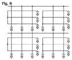
[0051] 更に別の実施形態では、図6について先に説明したように、容量の測定は、センサー・エレメントから接地まで測定することによって、しかし列の一部および/または行の一部を延長したセンサー・エレメントを用いて、行うことができる。これを図8に示す。このように、接触の位置は、行800の長さおよび/または列802の長さに沿って、一層正確に判定することができる。図示した実施形態では、各行800および各列802は接地に至る2つの接続を有するが、各行および/または各列が有する接地への接続は、適した数であればいずれでもよいことは言うまでもない。電源と接地との間において用いるセンサー・エレメントを少なくする程、所与のセンサー・サイズに対する、接触位置の判定を一層正確に行うことが可能になると考えられる。更に他の実施形態では、各センサー「画素」は、電源および接地へのそれ自体の接続によって、個々の容量回路を備えることができる。 [0051] In yet another embodiment, as described above with respect to FIG. 6, the capacitance measurement is performed by measuring from the sensor element to ground, but extending a portion of the column and / or a portion of the row. This can be done using the sensor element. This is shown in FIG. In this way, the location of contact can be determined more accurately along the length of row 800 and / or the length of column 802. In the illustrated embodiment, each row 800 and each column 802 has two connections leading to ground, but it will be appreciated that each row and / or each column may have any suitable number of connections to ground. . It is believed that the fewer sensor elements used between power and ground, the more accurately the contact location can be determined for a given sensor size. In still other embodiments, each sensor “pixel” may comprise an individual capacitive circuit, with its own connection to power and ground.
[0052] 手短に図5を再度参照すると、容量センサー・エレメント510は適した間隔であればいずれでも有することができる。例えば、実施形態の中には、センサー・エレメント510が、隣接するセンサー・エレメントの中心間で約1から5ミリメートルの間隔を有する場合がある。このサイズのセンサー・エレメントは十分に小さく、タッチ・センサーに接触する指は少なくとも2つのセンサー・エレメントの範囲内にある。これは、大人の人差し指が接触センサーに接触するとき非常に大まかに直径10mmの接触面積を有するからである。このようなセンサーを用いると、指が多数のセンサー・エレメントをカバーするときには一層正確な位置を内挿補間することができるので、実質的な分解能をセンサー・サイズよりも細かくすることができることが認められよう。他の実施形態では、センサー・エレメントの間隔は5mmよりも狭い場合もある。しかしながら、この場合、行および列の数が増大するので、タッチ・センサーのコストが上昇する可能性がある。同様に、実施形態の中には、センサー・エレメント間の間隔が5mmよりも広い場合もある。しかしながら、この場合、センサーは、指が1つのセンサー・エレメントに接触できる程に十分大きくすることができるが、指の位置を判定するのが困難となり、したがってセンサー分解能の低下を招く可能性がある。 [0052] Referring briefly to FIG. 5, capacitive sensor element 510 may have any suitable spacing. For example, in some embodiments, sensor element 510 may have a spacing of about 1 to 5 millimeters between the centers of adjacent sensor elements. A sensor element of this size is small enough that the finger touching the touch sensor is within the range of at least two sensor elements. This is because the adult index finger has a very roughly 10 mm diameter contact area when contacting the contact sensor. It is recognized that with such a sensor, the actual resolution can be made finer than the sensor size because a more accurate position can be interpolated when the finger covers a large number of sensor elements. I will be. In other embodiments, the sensor element spacing may be less than 5 mm. However, this increases the number of rows and columns, which can increase the cost of the touch sensor. Similarly, in some embodiments, the spacing between sensor elements is wider than 5 mm. However, in this case, the sensor can be large enough to allow the finger to touch one sensor element, but it is difficult to determine the position of the finger and thus can reduce sensor resolution. .
[0053] センサー・エレメント510には、適したセンサー・サイズおよび数であればいずれでも用いることができる。例えば、実施形態の中には、約100mm×50mmアレイのセンサー・エリアを用いてもよい場合がある。図6の実施形態では、m×n行を有するこのようなセンサーは、m+nに等しい数の列および行を有することができ、m+n回の容量測定によって、センサー全体の読み取り値を求めることができる。しかしながら、この実施形態では、ユーザーが多数の行および/または多数の列に一度に接触している場合、接触の位置に関して、多少の曖昧さが存在する可能性がある。例えば、ユーザーが
行AおよびBならびに列2および3に接触している場合、ユーザーが位置(A,2)および(B,3)に接触しているのか、または位置(A,3)および(B,2)に接触しているのか判断することが難しい場合がある。図8のコンテキストで説明するが、センサー・エレメントの各行および/または各列において接地に至る多数の接続を用いることによって、この曖昧さをある程度克服することができる。
[0053] Any suitable sensor size and number may be used for the sensor element 510. For example, in some embodiments, a sensor area of about 100 mm × 50 mm array may be used. In the embodiment of FIG. 6, such a sensor having m × n rows can have a number of columns and rows equal to m + n, and the total sensor reading can be determined by m + n capacitance measurements. . However, in this embodiment, if the user is touching many rows and / or many columns at once, there may be some ambiguity regarding the location of the contact. For example, if the user is in contact with rows A and B and columns 2 and 3, the user is in contact with positions (A, 2) and (B, 3), or positions (A, 3) and ( It may be difficult to determine whether or not B, 2) is touching. As described in the context of FIG. 8, this ambiguity can be overcome to some extent by using multiple connections leading to ground in each row and / or each column of sensor elements.
[0054] 対照的に、そして再度図7を参照すると、1つのセンサー・エレメントから他のセンサー・エレメントへの容量が接触された場合、m×n回の測定を行うことができる。これは、各行から各列への容量を測定することができるからである。この場合、多数の列および/または多数の行にわたって接触が生じたとき、各接触位置を独立して解明することができる。 [0054] In contrast, and referring again to FIG. 7, if the capacitance from one sensor element to another sensor element is contacted, m × n measurements can be made. This is because the capacity from each row to each column can be measured. In this case, when contact occurs over multiple columns and / or multiple rows, each contact location can be resolved independently.
[0055] m×n測定の実施形態を用いることは、状況によっては、m+n測定の実施形態を用いる場合よりも優位性を提供することができる。例えば、ユーザーが使用中にコンピューター・マウスを握っていると、多数の偶発的な接触が起こり得る。前述のm+n法で接触入力の正確な位置を判定する曖昧さのために、このような外部接触を無視する探索法は、m×n法と比較して、m+n法に合わせて練り上げる方が一層困難になる可能性がある。何故なら、m×nは各センサー・エレメントにおける容量を独立して解明することができるからである。 [0055] Using the m × n measurement embodiment may provide advantages over using the m + n measurement embodiment in some circumstances. For example, if a user is holding a computer mouse while in use, many accidental contacts can occur. Due to the ambiguity of determining the exact position of the contact input by the m + n method, the search method ignoring such external contact is more refined according to the m + n method than the m × n method. It can be difficult. This is because mxn can resolve the capacitance at each sensor element independently.
[0057] 更に別の実施形態では、センサーがm+nおよびm×n検出方法双方を利用することもできる。例えば、m×n測定の方がより多くの詳細を提供するが、測定する回数が多いために、より多くのデバイス電力を消費する可能性がある。したがって、接触状態の変化が検出されるまで、m+n検出方法を用いてセンサーを読み取るとよい。次いで、m×n測定を実行し、変化した接触状態について更に詳細な情報を収集した後に、m+n測定を再開するとよい。これについては、図24のコンテキストで以下で更に詳細に説明する。 [0057] In yet another embodiment, the sensor may utilize both m + n and mxn detection methods. For example, an mxn measurement provides more details, but may consume more device power due to more measurements. Therefore, the sensor may be read using the m + n detection method until a change in contact state is detected. The m + n measurement may then be performed and after collecting more detailed information about the changed contact state, the m + n measurement may be resumed. This is described in more detail below in the context of FIG.
[0058] タッチ・センサー410は、適した態様であればいずれでも、そして適した材料であればいずれでも製作することができる。例えば、接触感応ディスプレイ・デバイス用の従来の容量性タッチ・センサーは、酸化インジウム錫(ITO)のような透明な導体を、絶縁ガラスまたはプラスチック基板上に堆積して作ることができる。このようなセンサーは、例えば、基板の前面上に行を形成し、基板の背面上に列を形成することによって(またはその逆)、または列および行を構成するITOの単一層によって、金属またはITOジャンパーを用いて形成することができる。 [0058] The touch sensor 410 can be fabricated in any suitable manner and in any suitable material. For example, a conventional capacitive touch sensor for a touch-sensitive display device can be made by depositing a transparent conductor such as indium tin oxide (ITO) on an insulating glass or plastic substrate. Such sensors can be made of metal or by, for example, forming rows on the front side of the substrate and forming columns on the back side of the substrate (or vice versa), or by a single layer of ITO that constitutes the columns and rows. It can be formed using an ITO jumper.
[0059] しかしながら、接触感応コンピューター・マウスまたはタッチ・センサーに合わせたこのような他の使用環境の場合、センサーを不透明にすればよい。更に、コンピューター・マウス用のタッチ・センサーは、接触感応ディスプレイに用いられるタッチ・センサーとは異なり、湾曲面を有する。したがって、コンピューター・マウス用の容量性タッチ・センサーは、他のプロセスによって製造すればよい。例えば、一実施形態では、湾曲容量性タッチ・センサーは、導電性インクを用いて、可撓性絶縁基板上にタッチ・センサーの列および行を印刷する(例えば、スクリーン印刷、インク・ジェット印刷、または他の適した印刷技法)ことによって、作ることができる。更に具体的な例として、銀ポリマーの厚膜をポリエステル基板上に印刷することができる。尚、この例は、例示のために紹介したのであって、限定であることは全く意図していないことは言うまでもない。 [0059] However, for such other use environments tailored to touch sensitive computer mice or touch sensors, the sensor may be opaque. Furthermore, the touch sensor for a computer mouse has a curved surface unlike the touch sensor used for the touch-sensitive display. Therefore, a capacitive touch sensor for a computer mouse may be manufactured by other processes. For example, in one embodiment, a curved capacitive touch sensor uses conductive ink to print columns and rows of touch sensors on a flexible insulating substrate (eg, screen printing, ink jet printing, Or other suitable printing technique). As a more specific example, a thick film of silver polymer can be printed on a polyester substrate. It should be noted that this example has been introduced for illustrative purposes and is not intended to be limiting at all.
[0060] 図9は、容量性マルチタッチ・センサーを有する湾曲した幾何学的外形の物体を形成する方法900の一実施形態を示す。コンピューター・マウスのコンテキストで示されているが、この概念は適した湾曲物体であれば他のいずれにも応用できることは言う
までもない。最初に、方法90は、902において、可撓性絶縁基板の第1側に第1組のセンサー・エレメントを形成するステップを含む。904に示すように、更に具体的な一実施形態では、この第1組のセンサー・エレメントは、厚膜のような可撓性基板上に導電性インクを印刷することによって形成することができる。同様に、接触トレースを形成することができる。次に、方法900は、906において、基板の第2側に第2組のセンサー・エレメントを形成するステップを含む。908に示すように、更に具体的な一実施形態では、第2組のセンサー・エレメントは、基板の第2側に導電性インクを印刷することによって形成し、これによってセンサーを形成することができる。接触トレースも、同様に形成することができる。次に、910に示すように、湾曲したマウス表面上でセンサーを折り曲げ、次いで912において示すように、マウス表面に固定し(例えば、接着材または他の適したメカニズムによって)、接触感応コンピューター・マウスを形成する。尚、センサーの電源、コントローラー等への電気接続はいずれも、適したやり方であればいずれでも作ることができることは言うまでもない。例えば、基板は、可撓性「テール」を含むことができ、ここにトレースを印刷し、他の回路に接続するために、マウス内部に導入することができる。
[0060] FIG. 9 illustrates one embodiment of a method 900 for forming a curved geometric object having a capacitive multi-touch sensor. Although shown in the context of a computer mouse, it goes without saying that this concept can be applied to any other suitable curved object. Initially, method 90 includes, at 902, forming a first set of sensor elements on a first side of a flexible insulating substrate. In one more specific embodiment, as shown at 904, this first set of sensor elements can be formed by printing a conductive ink on a flexible substrate, such as a thick film. Similarly, contact traces can be formed. Next, the method 900 includes, at 906, forming a second set of sensor elements on the second side of the substrate. In one more specific embodiment, as shown at 908, the second set of sensor elements can be formed by printing a conductive ink on the second side of the substrate, thereby forming a sensor. . Contact traces can be similarly formed. Next, as shown at 910, the sensor is folded over a curved mouse surface and then secured to the mouse surface (eg, by adhesive or other suitable mechanism) as shown at 912, and a touch sensitive computer mouse. Form. It goes without saying that any electrical connection to the sensor power supply, controller, etc. can be made in any suitable way. For example, the substrate can include a flexible “tail” where traces can be printed and introduced inside the mouse for connection to other circuitry.
[0061] 図10は、容量性マルチタッチ・センサーを有するコンピューター・マウスを形成する方法の他の実施形態を示す。方法10は、1002において、例えば、印刷によって基板の第1側上に第1組のセンサー・エレメント(およびトレース)を形成し、次いで、1004において、第1組のセンサー・エレメント上に誘電体層を形成するステップを含む。次に、方法1000は、1006において、誘電体層上に第2組のセンサー・エレメント(およびトレース)を形成して、センサーを形成するステップを含む。次いで、1008において、方法1000は、マウスの表面上でセンサーを折り曲げ、次いでセンサーをマウス表面に固定して、接触感応コンピューター・マウスを形成するステップを含む。 [0061] FIG. 10 illustrates another embodiment of a method of forming a computer mouse having a capacitive multi-touch sensor. The method 10 forms a first set of sensor elements (and traces) on the first side of the substrate, for example by printing, at 1002, and then at 1004 a dielectric layer on the first set of sensor elements. Forming a step. Next, the method 1000 includes, at 1006, forming a second set of sensor elements (and traces) on the dielectric layer to form a sensor. Then, at 1008, the method 1000 includes folding the sensor on the surface of the mouse and then securing the sensor to the mouse surface to form a touch sensitive computer mouse.
[0062] 図11は、コンピューター・マウス用マルチタッチ・センサーを形成する方法1100の他の実施形態を示す。最初に、1102において、1つの層に第1および第2組のセンサー・エレメントを印刷し、第1組のセンサーにコネクターを形成する。次に、1104において、ジャンパーを形成する領域、即ち、第1組のセンサーのコネクターの上に、絶縁材料を堆積する。次に、1106において、導電性ジャンパーを絶縁材料上に堆積して、第2組のセンサーにコネクターを形成して、センサーを完成させる。このプロセスを図21に示す、以下で説明する。次いで、先に説明したように、センサーをコンピューター・マウスに固定することができる。尚、これらの実施形態は、例示のために紹介したのであって、限定であることは全く意図していないことは言うまでもない。 [0062] FIG. 11 illustrates another embodiment of a method 1100 for forming a multi-touch sensor for a computer mouse. Initially, at 1102, a first and second set of sensor elements are printed on one layer to form a connector on the first set of sensors. Next, at 1104, an insulating material is deposited over the areas where the jumpers are to be formed, i.e. over the connectors of the first set of sensors. Next, at 1106, a conductive jumper is deposited on the insulating material to form a connector on the second set of sensors to complete the sensor. This process is described below, shown in FIG. The sensor can then be secured to a computer mouse as previously described. It should be noted that these embodiments have been introduced for illustrative purposes and are not intended to be limiting at all.
[0063] 適した基板であればいずれでも、導電性インクを印刷する基板として用いることができる。適した基板の一例には、約0.003インチの厚さを有するポリエステル・シートを含む。他の実施形態では、他の適した可撓性絶縁材料であればいずれでも基板を作ることができ、適した厚さであれば他のいずれでも有することができる。同様に、導電性インクも、適した厚さであればいずれでも有することができる。具体的な一実施形態では、各センサー・エレメントを形成する導電性インクは、約0.001インチの厚さを有する。他の実施形態では、導電性インクは、適した厚さであれば他のいずれでも有することができる。 [0063] Any suitable substrate can be used as the substrate on which the conductive ink is printed. An example of a suitable substrate includes a polyester sheet having a thickness of about 0.003 inches. In other embodiments, the substrate can be made of any other suitable flexible insulating material and can have any other suitable thickness. Similarly, the conductive ink can have any suitable thickness. In one specific embodiment, the conductive ink forming each sensor element has a thickness of about 0.001 inch. In other embodiments, the conductive ink can have any other suitable thickness.
[0064] このようなセンサーにおける厚いポリマー導電性インク膜の電気的特性は、ガラス上のITOよりも低い面抵抗を有することができる。例えば、銀インクの厚膜は、更に低い面抵抗を有する(ITOが数十または数百オームであるのに対して、銀導電性インクでは〜40ミリオーム)。このため、センサーの列および行に沿ったRC遅延が減少することができ、したがってより長いトレース上でより速い測定が、少ない誤差で行うこと
が可能になる。更に、実施形態の中には、銀インクの代わりに、炭素導電性インクを用いることができる場合もある。炭素インクは、銀インクよりも安価であり、適した低抵抗を有することもできる。
[0064] The electrical properties of a thick polymer conductive ink film in such a sensor can have a lower sheet resistance than ITO on glass. For example, a thick film of silver ink has a lower sheet resistance (˜40 milliohms for silver conductive ink compared to tens or hundreds of ITO for ITO). This can reduce the RC delay along the sensor columns and rows, thus allowing faster measurements on longer traces with less error. Further, in some embodiments, carbon conductive ink can be used instead of silver ink. Carbon ink is less expensive than silver ink and can also have a suitable low resistance.
[0065] 図9から図11に示した方法は、マウスまたは他の物体の「可展面」に合わせてマルチタッチ・センサーを形成するのに適している。「可展面」という用語は、本明細書において用いる場合、歪み(例えば、圧縮および/または伸張)なく平面に平坦化することができる表面のことを言う。図12は、このような可展面を有するコンピューター・マウス1200の一実施形態例を示す。具体的には、可展面は、コンピューター・マウスの左縁端(図12におけるコンピューター・マウスの向きに言及する)から、マウスの軸に沿って、マウスが右ボタン縁端に向かって下方に湾曲し始める位置(破線1202で示す)まで広がっている。マウス1200のこの部分に取り付けられるタッチ・センサーは、通常の使用中にユーザーの指が接触する位置にあり、したがってユーザーの指が行うタッチ・ジェスチャーを検出することができる。 [0065] The method illustrated in FIGS. 9-11 is suitable for forming a multi-touch sensor to match the “expandable surface” of a mouse or other object. The term “developable surface” as used herein refers to a surface that can be flattened in a plane without distortion (eg, compression and / or stretching). FIG. 12 shows an example embodiment of a computer mouse 1200 having such a developable surface. Specifically, the developable surface extends from the left edge of the computer mouse (referring to the orientation of the computer mouse in FIG. 12) downward along the mouse axis toward the right button edge. It extends to a position where it begins to curve (indicated by a broken line 1202). A touch sensor attached to this portion of the mouse 1200 is in a position where the user's finger contacts during normal use, and thus can detect a touch gesture made by the user's finger.
[0066] 他の実施形態では、コンピューター・マウスが、複雑な湾曲がある非可展面上に配置されたタッチ・センサーを備えることもできる。図13は、非可展面上で用いるためのマルチタッチ・センサーを有するコンピューター・マウスを形成する方法1300の一実施形態を示す。この方法は、非可展面に取り付ける前に、センサーを折り曲げるステップを含む。方法1300は、1302において、折り曲げてはいけない基板の領域において、基板上に第1および第2組のセンサー・エレメントを形成するステップを含む。第1および第2組のセンサー・エレメントは、以上の方法900から1100のいずれにおいて説明したように、または適したやり方であれば他のいずれでも形成することができる。 [0066] In other embodiments, a computer mouse can include a touch sensor disposed on a non-expandable surface with complex curvature. FIG. 13 illustrates one embodiment of a method 1300 for forming a computer mouse having a multi-touch sensor for use on a non-developable surface. The method includes the step of bending the sensor prior to attachment to the non-expandable surface. The method 1300 includes, at 1302, forming first and second sets of sensor elements on the substrate in a region of the substrate that should not be folded. The first and second sets of sensor elements can be formed as described in any of the methods 900 to 1100 above or in any other suitable manner.
[0067] 次に、方法1300は、1304において、折り曲げるべき基板の領域において電気トレースを形成するステップを含む。このようなトレースは、例えば、折り曲げられる基板の領域によって空間的に分離されたセンサー・エレメントを接続するために形成することができる。次に、方法1300は、1306において、センサーを取り付けるべきマウス表面の複雑な湾曲と一致する形状に基板を折り曲げるステップと、次いで1308において、センサーをマウス表面に固定するステップとを含む。このように、製造中最初は平坦である基板を、非可展面に一致するように形作ることができる。次いで、可撓性プラスチック基板上の導電性ポリマー厚膜インクを用いて同様に印刷された可撓性「テール」によって、マウス内部に位置する印刷回路ボード上にある電子回路にセンサーを接続することができる。このようなテールは、ZIFまたは他の可撓性コネクターを用いて、印刷回路ボードに接続することができ、または単にそれをボード上のコンタクトに押圧することによって接続することができる。 [0067] Next, the method 1300 includes, at 1304, forming electrical traces in the region of the substrate to be folded. Such traces can be formed, for example, to connect sensor elements that are spatially separated by the area of the substrate to be folded. Next, the method 1300 includes, at 1306, folding the substrate into a shape that matches the complex curvature of the mouse surface to which the sensor is to be attached, and then at 1308, securing the sensor to the mouse surface. In this way, a substrate that is initially flat during manufacture can be shaped to conform to the non-developable surface. The sensor is then connected to an electronic circuit on a printed circuit board located inside the mouse by a flexible “tail” that is also printed using conductive polymer thick film ink on a flexible plastic substrate. Can do. Such a tail can be connected to a printed circuit board using a ZIF or other flexible connector, or simply by pressing it against a contact on the board.
[0068] 尚、基板を折り曲げることに加えて、非可展面に合わせてそれを折り曲げるためまたはそれ以外でその形状に合わせるために、切断してもよいことは言うまでもない。しかしながら、使用環境によっては、折り曲げが切断よりも実用的であることもある。何故なら、電気接続は、切断領域と比較して、折り曲げ領域に維持するとよいからである。同様に、ポリマーの厚膜インクは、鋭い折り目(crease)があっても、剥離を生じないことまたは折り目を跨いで接触を維持できなくならないことが評価できることも言うまでもない。 [0068] Needless to say, in addition to bending the substrate, the substrate may be cut in order to bend it in conformity with the non-expandable surface or otherwise conform to its shape. However, depending on the usage environment, folding may be more practical than cutting. This is because the electrical connection should be maintained in the folded region compared to the cut region. Similarly, it goes without saying that polymer thick film inks can be evaluated as having no detachment or inability to maintain contact across the crease, even with sharp creases.
[0069] 図14は、コンピューター・マウスの非可展面上に配置された容量性マルチタッチ・センサーを有するコンピューター・マウスを形成する方法1400の他の実施形態を示す。方法1400は、1402において、コンピューター・マウスの表面上に直接第1組のセンサー・エレメントを形成するステップを含む。この第1組のセンサー・エレメ
ントは、例えば、1404に示すように、コンピューター・マウスの表面上に導電性インクをパッド印刷(pad printing)することによって形成することができる。パッド印刷とは、可撓性パッド上に最初にパターンを印刷し、次いで可撓性パッドを他の表面に対して押圧し、パターンをその表面に転移させるプロセスである。実施形態の中には、1406に示すように、マウス本体の内面上に導電性インクを印刷するとよい場合もあり、一方他の実施形態では、1408に示すように、マウス本体の外面上に導電性インクを印刷するとよい場合もある。マウス本体の内面上に導電性インクを印刷する場合、マウス本体は、マウス本体に接触する指がセンサーによって検出可能となる効果を得るために、十分に薄くする(例えば、約0.5mm)とするとよい。
[0069] FIG. 14 illustrates another embodiment of a method 1400 of forming a computer mouse having a capacitive multi-touch sensor disposed on the non-expandable surface of the computer mouse. The method 1400 includes, at 1402, forming a first set of sensor elements directly on the surface of the computer mouse. This first set of sensor elements can be formed, for example, by pad printing conductive ink on the surface of a computer mouse, as shown at 1404. Pad printing is the process of first printing a pattern on a flexible pad and then pressing the flexible pad against another surface to transfer the pattern to that surface. In some embodiments, conductive ink may be printed on the inner surface of the mouse body, as shown at 1406, while in other embodiments, conductive ink is applied on the outer surface of the mouse body, as shown at 1408. In some cases, it may be desirable to print the ink. When printing conductive ink on the inner surface of the mouse body, the mouse body is sufficiently thin (for example, about 0.5 mm) to obtain an effect that the finger that contacts the mouse body can be detected by the sensor. Good.
[0070] 引き続き図14を見ていくと、方法1400は次に、1410において、第1組のセンサー・エレメント上に誘電体層を形成するステップと、次いで1412において、第1組のセンサー・エレメント上に第2組のセンサー・エレメントを形成するステップを備えている。他の実施形態では、第1および第2組のセンサー・エレメントは、それぞれ、マウス本体の内面および外面上に形成することもできる。 [0070] Continuing with FIG. 14, the method 1400 then forms a dielectric layer on the first set of sensor elements at 1410 and then at 1412 the first set of sensor elements. Forming a second set of sensor elements thereon. In other embodiments, the first and second sets of sensor elements may be formed on the inner and outer surfaces of the mouse body, respectively.
[0071] 圧電インクを用いることによって、付加的におよび/または代替的に力を測定することができる。例えば、圧電インクの層を、異なる基板上に組み立てられたセンサーの行および列の間に挿入することができる。このような構成では、電流がセンサーの平面に対して垂直に流れることができる。他の例として、センサーの行および列を同じ基板上に組み立てるとき(行および列をマトリクス状に接続するジャンパーを用いて)、圧電インクの層をセンサーの上に積層することもできる。このような構成では、電流はセンサーの平面内を流れることができる。行および列間のインピーダンスは、抵抗および容量の並列組み合わせと考えられる。2つの分離した周波数において測定することによって、容量および抵抗を独立して測定することができる。これについては、図21から図23のコンテキストにおいて以下で更に詳細に説明する。 [0071] Force can be measured additionally and / or alternatively by using piezoelectric inks. For example, a layer of piezoelectric ink can be inserted between the rows and columns of sensors assembled on different substrates. In such a configuration, current can flow perpendicular to the plane of the sensor. As another example, when the sensor rows and columns are assembled on the same substrate (using jumpers that connect the rows and columns in a matrix), a layer of piezoelectric ink can be laminated over the sensor. In such a configuration, current can flow in the plane of the sensor. The impedance between rows and columns can be considered as a parallel combination of resistance and capacitance. By measuring at two separate frequencies, the capacitance and resistance can be measured independently. This is described in more detail below in the context of FIGS.
[0072] 次に、方法1400は、1414において、第2組のセンサー・エレメント上に保護層を形成するステップを含む。このような保護層は、例えば、1416に示すように、第2組のセンサー・エレメント上に誘電体塗料を塗布することによって、または1418に示すように、第2組のセンサー・エレメント上に薄いプリモールド・シェルを取り付けることによって、または他の何らかの適したプロセスによって形成することができる。このように、容量性マルチタッチ・センサーは、マウス本体に後から固定される基板上ではなく、マウス本体上に直接形成することができる。このような実施形態に合わせた相互接続は、適したやり方であればいずれでも形成することができる。このセンサーに相互接続を形成するのに適した方法の一例には、一部の液晶ディスプレイにおいて用いられている「ゼブラ・ストライプ」と同様の、異方導電性を有する共形材料を用いて相互接続を形成するステップを含むことができる。 [0072] Next, the method 1400 includes, at 1414, forming a protective layer over the second set of sensor elements. Such a protective layer is thin, for example, by applying a dielectric coating on the second set of sensor elements, as shown at 1416, or on the second set of sensor elements, as shown at 1418. It can be formed by attaching a pre-molded shell or by some other suitable process. In this way, the capacitive multi-touch sensor can be formed directly on the mouse body, not on a substrate that is later fixed to the mouse body. Interconnects tailored to such embodiments can be formed in any suitable manner. An example of a suitable method for forming interconnects in this sensor is to use a conformal material with anisotropic conductivity, similar to the “zebra stripe” used in some liquid crystal displays. A step of forming a connection can be included.
[0073] 図15は、いわゆる「インモールド・デコレーション」プロセスによって、コンピューター・マウスの非可展面上に容量性マルチタッチ・センサーを形成する方法1500の他の実施形態を示す。方法1500は、1502において、「箔」を形成するステップと、1504において、この箔上に第1および第2組のセンサー・エレメントを印刷するステップとを含む。この箔は、箔上に印刷されているパターンが成形の間に被成形品目に転移されるように、マウス本体成形プロセスの間型の中に置かれるインサートである。つまり、方法1500は、次に1506において、この箔の上に第1および第2組のセンサー・エレメントを印刷したものを、型の中に挿入するステップと、1508において、型の中でマウス本体を成形することによって、パターンをマウス本体に転移させるステップとを含む。箔は、成形の間、被成形品目に組み込まれても、組み込まれなくてもよい。同様に、成形プロセスの間に、電気トレースをマウス本体上に形成することができる。 FIG. 15 illustrates another embodiment of a method 1500 for forming a capacitive multi-touch sensor on a non-expandable surface of a computer mouse by a so-called “in-mold decoration” process. The method 1500 includes forming a “foil” at 1502 and printing a first and second set of sensor elements on the foil at 1504. This foil is an insert that is placed in the mold during the mouse body molding process so that the pattern printed on the foil is transferred to the molded item during molding. That is, the method 1500 then inserts in 1506 a first and second set of sensor elements printed on the foil into the mold, and in 1508 the mouse body in the mold. Transferring the pattern to the mouse body by molding. The foil may or may not be incorporated into the molded item during molding. Similarly, electrical traces can be formed on the mouse body during the molding process.
[0074] 実施形態の中には、マウス表面上に印刷された導電性材料が、昇華する材料であるとよい場合がある。このような実施形態では、センサー・アレイをマウスの本体のバルク材料に昇華させることができ、これによってセンサー・アレイを直接マウス本体に組み込むことができる。 [0074] In some embodiments, the conductive material printed on the mouse surface may be a material that sublimes. In such an embodiment, the sensor array can be sublimated to the bulk material of the mouse body, which allows the sensor array to be incorporated directly into the mouse body.
[0075] 方法900、1000、1100、1300、1400、および1500のコンテキストにおいて以上で説明したセンサーは、容量を検知するように構成されている。これによって、センサーは、人の指がセンサー上の指定点に近接しているか否か検出することが可能になるが、指が押圧している力を直接検出しない。以下で更に詳細に説明するが、この力は、接触入力の接地面積(contact patch area)を測定することによって、間接的に測定することができる。この面積は、指の肉の平坦化のために、指で押下する力が大きい程広くなる。実施形態の中には、力の測定は、センサーを、力を電気容量に変換する変換器と積層することによって、得られるようにすることができるものもある。このような変換器の一例は、液晶材料のように、圧力に感応する誘電係数を有する材料である。尚、この圧力センサーの例は、例示のために紹介したのであって、限定であることは全く意図していないことは言うまでもない。 [0075] The sensors described above in the context of methods 900, 1000, 1100, 1300, 1400, and 1500 are configured to sense capacitance. This allows the sensor to detect whether a person's finger is close to a designated point on the sensor, but does not directly detect the force that the finger is pressing. As described in more detail below, this force can be measured indirectly by measuring the contact patch area of the contact input. This area becomes wider as the force of pressing with the finger is larger in order to flatten the flesh of the finger. In some embodiments, force measurements can be obtained by laminating a sensor with a transducer that converts force to capacitance. An example of such a transducer is a material having a dielectric coefficient that is sensitive to pressure, such as a liquid crystal material. Needless to say, this example of a pressure sensor has been introduced for illustrative purposes and is not intended to be limiting at all.
[0076] 前述のように、接触感応面を有するマウスは、1つ又は複数の光源を備えることができ、特定の機能にマッピングされている接触感応面の領域の輪郭を定めるために、光源を選択的に照明することができる。例えば、図16は、スクロール・ホイールのような機能にマッピングされている領域1602を備えているコンピューター・マウス1600の一実施形態を示す。ユーザーは、例えば、領域1602に沿ってコンピューター・マウス1600の長軸に対して前後に指をはじくまたはドラッグすることによって、リストをスクロールすることができる。 [0076] As mentioned above, a mouse having a touch-sensitive surface can be equipped with one or more light sources, and the light source can be used to delineate regions of the touch-sensitive surface that are mapped to a particular function. Can be selectively illuminated. For example, FIG. 16 shows one embodiment of a computer mouse 1600 that includes an area 1602 that is mapped to a function such as a scroll wheel. The user can scroll through the list, for example, by flicking or dragging a finger back and forth with respect to the long axis of the computer mouse 1600 along the area 1602.
[0077] しかしながら、コンピューター・マウス1600は平坦で造作(feature)のない表面を有すると、アクティブになったときにその機能を示さないことがあるので、コンピューター・マウス1600は1つ又は複数の光源を備えるとよく、これらの光源は、領域1602がスクロール・ホイール機能にマッピングされているときに、この領域の輪郭を定めるように照明することができる。図示した実施形態では、領域1602の境界1604が照明されているが、他の実施形態では、適した方法であれば他のいずれによってこの領域を示してもよいことは言うまでもない。例えば、他の実施形態では、領域全体1602(単に領域の周囲だけでなく)を照明してもよい。スクロール・ホイール機能にマッピングされた領域のコンテキストで示したが、いずれかの特定的な機能にマッピングされたコンピューター・マウス1600のいずれの適した領域でも、光源によって同様に示すことができることは言うまでもない。 [0077] However, if the computer mouse 1600 has a flat, feature-free surface, the computer mouse 1600 may not exhibit its function when activated, so the computer mouse 1600 may have one or more light sources. These light sources can be illuminated to delineate the area 1602 when it is mapped to the scroll wheel function. In the illustrated embodiment, the boundary 1604 of the region 1602 is illuminated, but it will be appreciated that in other embodiments this region may be indicated by any other suitable method. For example, in other embodiments, the entire area 1602 (not just around the area) may be illuminated. Although shown in the context of an area mapped to a scroll wheel function, it will be appreciated that any suitable area of the computer mouse 1600 mapped to any particular function can be similarly indicated by a light source. .
[0078] 適したタイプの光源であればいずれでも、領域1602を照明するために用いることができる。例えば、実施形態の中には、1つ又は複数の光管(即ち、全内反射光導管)を用いて、マウス内部にある発光ダイオードまたは他の発光体から、マウス表面のタッチ・センサー上の位置に光を伝えることもできる。他の実施形態の中には、光源が電気泳動インクを含むとよい場合もある。更に他の実施形態では、光源は、タッチ・センサーの直下から光を放出するように構成することもできる。このような実施形態では、タッチ・センサーは、ITOのような透明導体を採用するとよい。透明導体は、ポリマーの厚い導電性インク膜とは異なり、光をセンサーに通過させる。あるいは、タッチ・センサーは、光が通過する領域を、いずれのトレースまたはセンサー・エレメントが邪魔にならないように残しておいて、光がセンサーを通過することを可能にするように製作することもできる。 [0078] Any suitable type of light source can be used to illuminate region 1602. For example, in some embodiments, one or more light tubes (ie, total internal reflection light conduits) are used on a touch sensor on the mouse surface from a light emitting diode or other light emitter inside the mouse. You can also transmit light to the position. In other embodiments, the light source may include electrophoretic ink. In yet other embodiments, the light source may be configured to emit light from directly below the touch sensor. In such an embodiment, the touch sensor may employ a transparent conductor such as ITO. Transparent conductors allow light to pass through the sensor, unlike polymer thick conductive ink films. Alternatively, the touch sensor can be fabricated to allow light to pass through the sensor, leaving any trace or sensor element out of the way. .
[0079] 図16に示した以外でも、適したやり方であれば他のいずれによってでも、特定の機能を示すことができる。例えば、実施形態の中には、特定の機能にマッピングされている特定の位置に区画を備えた、薄いプラスチップ製のスナップ・オン・カバー(snap-on cover)を設けるとよい場合がある。図17は、このようなマウス・カバー1700の一例を示し、カバー1700の中心に配置された区画1702が、スクロール・ホイール機能にマッピングされたマウスの領域に対応する。マウス・カバー1700は、コードを含むことができ、マウスがカバーを識別し、そのカバーに対して予め設定されているタッチ・センサーを参照することをマウスに可能にするために、そのコードをマウスによって読み取ることができる。このようなカバーには、例えば、ゲームまたは他のソフトウェアを供給し、タッチ・センサをゲームまたは他のソフトウェアの機能に自動的にマッピングすることもできる。一実施形態では、コードは、マウスのタッチ・センサーによって読み取り可能な、1つ又は複数の導電性エレメント1704を備えている。他の実施形態では、このコードは、マウスにおける光検出器によって読み取ることができる光学読み取り可能コード(例えば、バー・コード)、または適したタイプのコードであれば他のいずれでも備えることができる。 [0079] In addition to those shown in FIG. 16, the particular function can be shown in any other suitable way. For example, in some embodiments, it may be desirable to provide a thin plus-chip snap-on cover with compartments at specific locations that are mapped to specific functions. FIG. 17 shows an example of such a mouse cover 1700, with the section 1702 located in the center of the cover 1700 corresponding to the area of the mouse mapped to the scroll wheel function. The mouse cover 1700 can include code that allows the mouse to identify the cover and allow the mouse to reference a preset touch sensor for the cover. Can be read by. Such a cover could be provided, for example, with a game or other software, and the touch sensor could be automatically mapped to a game or other software function. In one embodiment, the code includes one or more conductive elements 1704 that are readable by a mouse touch sensor. In other embodiments, the code can comprise an optically readable code (eg, a bar code) that can be read by a photodetector in the mouse, or any other suitable type of code.
[0080] 尚、適した機能または複数の機能であれば他のいずれでも、マウスのタッチ・センサー上の特定の領域にマッピングできることは認められよう。例えば、先に説明したように、コンピューター・マウスのタッチ・センサーの右側を「右クリック」機能にマッピングすることができ、左側を「左」クリック機能にマッピングすることができる。更に、二次元パンニング機能を、スプレッドシートをナビゲートする間に使用するために、タッチ・センサーの正方形領域にマッピングすることもできる。加えて、ビデオ編集アプリケーションにおいてタイムライン全域で素早く動かすために、「スクラブ」(scrub)機能をタッチ・センサーの環状領域にマッピングすることができる。尚、これらの具体的な機能は、例示のために紹介したのであって、限定であることは全く意図していないことは言うまでもない。 [0080] It will be appreciated that any other suitable function or functions can be mapped to a particular area on the mouse touch sensor. For example, as described above, the right side of a computer mouse touch sensor can be mapped to a “right click” function and the left side can be mapped to a “left” click function. In addition, a two-dimensional panning function can be mapped to the square area of the touch sensor for use while navigating the spreadsheet. In addition, a “scrub” function can be mapped to the annular area of the touch sensor for quick movement across the timeline in video editing applications. Needless to say, these specific functions have been introduced for illustrative purposes and are not intended to be limiting at all.
[0081] 領域と機能との関連付けは、ソフトウェアで任意に変更することができるので、特定のタッチ・センサー領域のマッピングをユーザーの好みまたは現在のタスクに適応させることもできる。例えば、コンピューティングデバイスの新米ユーザーが、従来のマウス上に多数のボタンがあると、混乱する可能性がある。したがって、このようなユーザーには、1つの機械式アクチュエーター(マウス本体全体が機械式ボタンとして動作するように)、およびタッチ・センサーも、最初は単純な一ボタン・マウスとして動作し、ユーザーの快適さおよび体験が増大するに連れて機能を増やしていくこともできる。 [0081] Since the association between regions and functions can be arbitrarily changed by software, the mapping of specific touch sensor regions can also be adapted to user preferences or current tasks. For example, a novice user of a computing device can be confused if there are a large number of buttons on a conventional mouse. Therefore, for such users, one mechanical actuator (so that the entire mouse body operates as a mechanical button) and touch sensor also operate as a simple one-button mouse at first, which is comfortable for the user. You can also increase functionality as your experience and experience grows.
[0082] このようなアクチュエーターを1つだけ有する機械式マウスでは、特定の機能を実行するための機械的作動に対する意図は、その機械的作動と関連のあるタッチ・センサーによって決定することができる。例えば、「左クリック」および「右クリック」機能を1つの機械式アクチュエーターによって呼び出す意図は、タッチ・センサーのそれぞれの右側および左側における接触入力の変化によって区別することができる。 [0082] In a mechanical mouse having only one such actuator, the intention for a mechanical actuation to perform a particular function can be determined by a touch sensor associated with that mechanical actuation. For example, the intention to invoke the “left click” and “right click” functions by one mechanical actuator can be distinguished by changes in the touch input on the respective right and left sides of the touch sensor.
[0083] 図18は、タッチ・センサー入力によって左および右クリックを区別する方法1800の一実施形態を示す。方法1800は、最初に1802において、機械式アクチュエーターの作動を検出するステップを含む。次に、1804において、方法1800は、マウス上における指の接触面積の増大を検出するステップを含む。このような増大は、例えば、指がマウス本体上において接触を開始することによって、または以前に置いた指がマウス本体上で圧力を増したために生ずる可能性がある。ユーザーが指でマウスを押圧する圧力量をユーザーが増大させると、その指のタッチ・センサー上における接触面積が増大すると考えられる。図19および図20は、この概念を示す。最初に図19を参照すると、マウス・タッチ・センサーの左側における接触が、タッチ・センサー出力において
1900で示されており、タッチ・センサーの右側における接触が、1902で示されている。次に図20を参照すると、ユーザーが「右クリック」入力を行おうとすると、ユーザーは右指でもっと多くの圧力をかけて、機械式アクチュエーターを作動させようとすることができる。この場合、右側の接触1902の接触面積が増大する。
[0083] FIG. 18 illustrates one embodiment of a method 1800 for distinguishing left and right clicks by touch sensor input. The method 1800 initially includes detecting a mechanical actuator actuation at 1802. Next, at 1804, the method 1800 includes detecting an increase in finger contact area on the mouse. Such an increase can occur, for example, by a finger initiating contact on the mouse body, or because a previously placed finger has increased pressure on the mouse body. When the user increases the amount of pressure with which the user presses the mouse, it is considered that the contact area of the finger on the touch sensor increases. 19 and 20 illustrate this concept. Referring initially to FIG. 19, contact on the left side of the mouse touch sensor is indicated at 1900 in the touch sensor output and contact on the right side of the touch sensor is indicated at 1902. Referring now to FIG. 20, when the user attempts to make a “right click” input, the user can apply more pressure with the right finger to attempt to actuate the mechanical actuator. In this case, the contact area of the right contact 1902 increases.
[0084] 引き続き図18を見ていくと、方法1800は次に、1806において、タッチ・センサー上の位置によって、マウス本体上における接触面積の増大に対応する指の位置を検出し、次いで1808において、その指が、特定の機能と関連付けられているマウス本体のエリア上に位置しているか否か判定するステップを含む。その接触が、特定の機能と関連付けられているマウス本体のエリアにおいて行われたのではない場合、方法1800は、1810において、機械式作動にデフォルト機能を割り当てるステップを含む。一方、特定的にマッピングされた機能と関連付けられたマウス本体のエリアにおいてその接触が行われたのであれば、方法1800は、1812において、そのエリアにマッピングされている特定の機能に、機械式作動を割り当てる。 [0084] Continuing with FIG. 18, the method 1800 then detects, at 1806, the position of the finger corresponding to the increase in contact area on the mouse body by position on the touch sensor, and then at 1808. Determining whether the finger is located on an area of the mouse body associated with a particular function. If the contact has not occurred in the area of the mouse body that is associated with a particular function, the method 1800 includes, at 1810, assigning a default function to the mechanical action. On the other hand, if the contact has been made in the area of the mouse body associated with the specifically mapped function, the method 1800, at 1812, performs a mechanical operation on the specific function mapped to that area. Assign.
[0085] 前述のように、実施形態の中は、マウスの表面に対する接触入力の圧力を検出するように構成されている圧力センサーを備えているとよいことがある。このような接触圧力検知によって、コンピューター・マウスのコントローラーは、「左クリック」、「右クリック」、およびマウス上にある機械式ボタンによって作動させられる他のこのような「仮想ボタン」動作の作動に対応する圧力信号を検出することが可能になる。更に、接触圧力検知は、マウス表面上における偶発的な接触が所定の圧力閾値を満たさない場合このような入力を無視することによって、マウス表面上における「スクロール・ホイール」起動動作のような種々の動作を、偶発的な接触入力から区別するために用いることができる。尚、接触感応マウスにおける圧力センサーの使用についてのこれらの例は、例示のために紹介したのであって、限定であることは全く意図していないことは言うまでもない。 [0085] As described above, some embodiments may include a pressure sensor configured to detect the pressure of the touch input to the surface of the mouse. Such contact pressure sensing allows the computer mouse controller to activate “left click”, “right click”, and other such “virtual button” movements activated by mechanical buttons on the mouse. A corresponding pressure signal can be detected. In addition, contact pressure sensing can be implemented in various ways, such as “scroll wheel” activation actions on the mouse surface, by ignoring such input if accidental contact on the mouse surface does not meet a predetermined pressure threshold. An action can be used to distinguish it from accidental touch input. Of course, these examples of the use of pressure sensors in touch-sensitive mice have been introduced for purposes of illustration and are not intended to be limiting in any way.
[0086] 適した圧力センサー、または適した圧力センサーの構成であればいずれでも、マウスにおいて容量性マルチタッチ・センサーと共に用いることができる。例えば、実施形態の中には、容量製タッチ・センサーを有するマウスが2つの圧力センサーを備えているものあり、「左クリック」入力(即ち、左マウス・ボタンが機械式マウス上で一般に見られる位置)を検出するように構成されている位置に1つが配置され、「右クリック」入力を検出するように構成されている位置にもう1つが配置されている。 [0086] Any suitable pressure sensor, or any suitable pressure sensor configuration, can be used with a capacitive multi-touch sensor in a mouse. For example, in some embodiments, a mouse with a capacitive touch sensor has two pressure sensors, and a “left click” input (ie, a left mouse button is commonly found on a mechanical mouse). One is placed at a position configured to detect (position), and another is placed at a position configured to detect a “right click” input.
[0087] 他の実施形態では、画素毎に圧力を検知できるように、圧力センサーが更に細かい分解能を有するように構成することもできる。画素毎(on a pixilated basis)に接触圧力を判定するためには、適した圧力センサーであればいずれでも用いることができる。例えば、実施形態の中には、圧電シート(即ち、圧電インクの層を備えているシート)をセンサー・アレイと共に用いて、接触圧力を検出することができる。このような圧電シートは、小さな導電性エレメントを散在させて備えている可撓性材料のシートである。このシートに対して圧力がかけられると、導電性エレメントの配列が変化する。これによって、シードの抵抗が、圧力を受けたエリアにおいて変化する。異なる電位を有する電極を備えているセンサー・アレイに対向して圧電シートを置くことによって、圧電シートの抵抗をセンサー・エレメント間で測定することができ、シートにかけられた圧力の大きさを検出することができる。尚、他の圧力感応可変抵抗材料も同様に用いることができることは言うまでもない。 [0087] In another embodiment, the pressure sensor can be configured to have a finer resolution so that the pressure can be detected pixel by pixel. Any suitable pressure sensor can be used to determine the contact pressure on an pixilated basis. For example, in some embodiments, a piezoelectric sheet (ie, a sheet comprising a layer of piezoelectric ink) can be used with a sensor array to detect contact pressure. Such a piezoelectric sheet is a sheet of flexible material with interspersed small conductive elements. When pressure is applied to the sheet, the arrangement of the conductive elements changes. This changes the seed resistance in the area under pressure. By placing a piezoelectric sheet opposite a sensor array with electrodes having different potentials, the resistance of the piezoelectric sheet can be measured between sensor elements and detects the amount of pressure applied to the sheet. be able to. Needless to say, other pressure-sensitive variable resistance materials can be used as well.
[0088] 実施形態の中には、容量性タッチ・センサーおよび抵抗性圧力センサー毎に、別々のセンサー・アレイを用いることもできる。例えば、圧電シートおよびセンサー・アレイを備えている抵抗性圧力センサーを、別のセンサー・アレイを有する容量性タッチ・センサーの上方または下方に配置することができる。他の実施形態では、容量性タッチ・
センサーおよび抵抗性圧力センサーが共通のセンサー・アレイを共有することもできる。図21および図22は、共通の電極アレイを共有する容量性マルチタッチ・センサーおよび抵抗性圧力センサーの構造を示す。最初に図21を参照すると、2100において、行センサー・エレメント2103および列センサー・エレメント2104のアレイにおいて基板2102上にポリマー導電性厚膜を印刷することによって、センサー・アレイを形成する。2100に示すように、コネクター2106を最初に一方向(列方向として示されている)に印刷する。次に、2108に示すように、列コネクター2106上に誘電体材料2110を堆積し、次いで2112において、誘電体材料上に行コネクター2114を印刷して、センサー・アレイを完成する。最後に、2116において、センサー上に圧電シート2118を被着する。圧電シート2118は、図21では、基礎構造を図示するために、一部分解図で示されている。
[0088] In some embodiments, a separate sensor array may be used for each capacitive touch sensor and resistive pressure sensor. For example, a resistive pressure sensor comprising a piezoelectric sheet and a sensor array can be placed above or below a capacitive touch sensor having another sensor array. In other embodiments, capacitive touch
Sensors and resistive pressure sensors can also share a common sensor array. 21 and 22 show the structure of a capacitive multi-touch sensor and a resistive pressure sensor that share a common electrode array. Referring first to FIG. 21, at 2100, a sensor array is formed by printing a polymer conductive thick film on a substrate 2102 in an array of row sensor elements 2103 and column sensor elements 2104. As shown at 2100, the connector 2106 is first printed in one direction (shown as a column direction). Next, as shown at 2108, a dielectric material 2110 is deposited on the column connector 2106 and then at 2112 a row connector 2114 is printed on the dielectric material to complete the sensor array. Finally, at 2116, a piezoelectric sheet 2118 is deposited on the sensor. The piezoelectric sheet 2118 is shown in a partially exploded view in FIG. 21 to illustrate the basic structure.
[0089] 図22に示すように、圧電シートは、隣接する行センサー・エレメント2103および列センサー・エレメント2104を、模式的に2200で示す、抵抗のある経路と接続する。隣接するセンサー・エレメント(m×n配列)の容量性結合が、2202において模式的に示されている。このように、各センサー・エレメントは、抵抗的および容量的双方で隣接するセンサー・エレメントに結合されている。したがって、異なる周波数において測定されたインピーダンス測定値から、抵抗値および容量値を計算することができる。このように、接触位置および接触圧力の測定を、同じ分解能で行うことができる。 [0089] As shown in FIG. 22, the piezoelectric sheet connects adjacent row sensor elements 2103 and column sensor elements 2104 with a resistive path, schematically shown at 2200. Capacitive coupling of adjacent sensor elements (m × n array) is shown schematically at 2202. Thus, each sensor element is coupled to adjacent sensor elements both resistively and capacitively. Therefore, the resistance value and the capacitance value can be calculated from the impedance measurement values measured at different frequencies. In this way, the measurement of the contact position and the contact pressure can be performed with the same resolution.
[0090] したがって、図23は、図21および図22の実施形態のような、1つのセンサー・アレイを利用する容量性マルチタッチ・センサーおよび抵抗性圧力センサーを備えているタッチ・センサーによって、接触位置および接触圧力を測定する方法2300の一実施形態を示す。方法2300は、2302において、第1インピーダンス測定値を得て、次いで2304において、異なる周波数において第2インピーダンス測定値を得るステップを含む。尚、このコンテキストにおける「インピーダンス測定値」という用語は、完全なセンサー読み取り値、即ち、センサー・アレイの画素毎のインピーダンス測定値を含むことは言うまでもない。 [0090] Accordingly, FIG. 23 is shown in FIG. 21 by a touch sensor comprising a capacitive multi-touch sensor and a resistive pressure sensor utilizing a single sensor array, such as the embodiment of FIGS. 1 illustrates one embodiment of a method 2300 for measuring position and contact pressure. The method 2300 includes obtaining a first impedance measurement at 2302 and then obtaining a second impedance measurement at a different frequency at 2304. It should be appreciated that the term “impedance measurement” in this context includes complete sensor readings, ie, impedance measurements for each pixel of the sensor array.
[0091] 次に、2306において、行った2回の測定に基づいて、抵抗値および容量値を決定する。実施形態の中には、2308で示すように、これら2つの値を総測定インピーダンスの大きさから決定するとよい場合がある。容量性リアクタンスおよび抵抗の総測定インピーダンスの大きさに対する寄与は、以下の式で示され、ここで|Z|は総測定インピーダンスの大きさであり、Xcは容量性リアクタスである。 Next, in 2306, the resistance value and the capacitance value are determined based on the two measurements performed. In some embodiments, as indicated by 2308, these two values may be determined from the magnitude of the total measured impedance. The contribution of capacitive reactance and resistance to the magnitude of the total measured impedance is given by: where | Z | is the magnitude of the total measured impedance and Xc is the capacitive reactance.
[0092] [0092]
![]()
![]()
ここで、
[0093]
here,
[0093]
![]()
![]()
[0094] 2回のインピーダンス測定は、総インピーダンスの抵抗成分が双方の場合にお
いて一定であり、容量Cも一定である(即ち、指の圧力および位置が測定中実質的に変化しなかった)という仮定が許容されるように、十分に次回時間間隔で行うとよい。これらの過程により、総インピーダンスの変化は、2回の測定を行った周波数の関数となる。このように、CおよびRは2つの測定値によって決定することができる。
[0094] Two impedance measurements indicate that the resistance component of the total impedance is constant in both cases, and the capacitance C is also constant (ie, finger pressure and position did not change substantially during the measurement). It should be done at the next time interval sufficiently to allow the assumption. Through these processes, the change in total impedance is a function of the frequency at which the two measurements were taken. Thus, C and R can be determined by two measurements.
[0095] 他の実施形態では、1210に示すように、無効容量および抵抗を、2つの測定インピーダンス間の位相角の差から決定することができる。これらの実施形態では、以下の関係を用いて、抵抗および容量性リアクタンスを決定することができる。 [0095] In other embodiments, as shown at 1210, reactive capacitance and resistance can be determined from the phase angle difference between the two measured impedances. In these embodiments, the following relationship can be used to determine resistance and capacitive reactance.
[0096] [0096]
![]()
![]()
[0097] 再度、R(即ち、接触圧力)およびC(即ち、接触位置)が一定であると仮定するために2回の測定が十分に短い時間間隔の間に行われたと仮定すると、測定された位相ずれは、無効容量の関数となり、したがって、測定が行われた周波数の関数となる。このように、RおよびCを位相ずれから決定することができる。 [0097] Again, assuming that two measurements were made during a sufficiently short time interval to assume that R (ie, contact pressure) and C (ie, contact position) are constant, The phase shift is a function of the reactive capacitance and therefore a function of the frequency at which the measurement was made. Thus, R and C can be determined from the phase shift.
[0098] 引き続き図23を見ていくと、方法2300は、次に2312において、決定された容量性リアクタンスから接触入力を検出し、それに応答して、接触入力にしたがってグラフィカル・ユーザー・インターフェースを操作するステップを含む。例えば、グラフィカル・ユーザー・インターフェース上に表示されている写真オブジェクト上にマウス制御カーソルがある間に検出された接触入力が「ピンチ」または「ストレッチ」ジェスチャーに対応する場合、写真オブジェクトのサイズを、検出された接触入力に応答して、変更することができる。 [0098] Continuing with FIG. 23, the method 2300 then detects a touch input from the determined capacitive reactance at 2312 and responsively manipulates the graphical user interface according to the touch input. Including the steps of: For example, if the touch input detected while the mouse control cursor is over a photo object displayed on a graphical user interface corresponds to a “pinch” or “stretch” gesture, the size of the photo object is detected. Can be changed in response to the touch input made.
[0099] 同様に、方法2300は、2314において、決定した抵抗から接触圧力を検出し、それに応答して、この圧力にしたがってグラフィカル・ユーザー・インターフェースを操作するステップを含む。例えば、検出された接触圧力がマウス本体の左前四分義の内部に位置し、所定の閾値圧力レベルを超過する場合、この特定の接触入力は、「左クリック」入力であると考えることができる。このため、応答してユーザー・インターフェース動作を行うことができる。更に具体的な一例として、マウス・カーソルがあるアイコン上に位置する場合、「左クリック」入力の検出が、アイコンによって表されるファイルを開かせ、そしてユーザー・インターフェース上に表示させることができる。 [0099] Similarly, the method 2300 includes, at 2314, detecting a contact pressure from the determined resistance and responsively manipulating the graphical user interface according to the pressure. For example, if the detected contact pressure is located within the left front quadrant of the mouse body and exceeds a predetermined threshold pressure level, this particular contact input can be considered a “left click” input. . Therefore, a user interface operation can be performed in response. As a more specific example, if the mouse cursor is positioned over an icon, detection of a “left click” input can cause the file represented by the icon to be opened and displayed on the user interface.
[00100] 使用環境の中には、マウス本体への接触だけでなく、マウス本体上接触至近(near-touch)イベントも検出することが望ましい場合もある。これは、「接触至近」状態の検出が追加の機能を可能にするからである。アレイがタイル状ネットワークのダイアモンド形状の列および行のセンサー・エレメントを備えている、本明細書において図示したセンサー・アレイの実施形態では、m+n容量測定が、m×n容量測定よりも高い感度を接触至近にもたらすことができる。その理由は、m+n容量測定は、m×n測定が行うような、隣接する行および列センサー・エレメントの縁端間の容量測定の代わりに、センサー・エレメントから接地までの容量を測定するからである。したがって、各センサー・エレメントの容量は、m+n構成の方がm×n構成におけるよりも大きくなり、接触至近を検出する感度の上昇が可能になる。 [00100] In some usage environments, it may be desirable to detect not only a touch on the mouse body but also a near-touch event on the mouse body. This is because the detection of the “close contact” state enables an additional function. In the sensor array embodiment illustrated herein, where the array comprises diamond shaped column and row sensor elements of a tiled network, the m + n capacitance measurement is more sensitive than the m × n capacitance measurement. Can be brought in close contact. The reason is that the m + n capacitance measurement measures the capacitance from the sensor element to ground instead of the capacitance measurement between the edges of adjacent row and column sensor elements as the m × n measurement does. is there. Therefore, the capacitance of each sensor element is larger in the m + n configuration than in the m × n configuration, and the sensitivity for detecting close proximity can be increased.
[00101] しかしながら、先に説明したように、m+n測定で得られる分解能は、m×
n測定よりも低く、したがって、接触入力の位置に関して多少の曖昧さが生ずる可能性がある。特に、接触が少なくとも部分的に行および列センサー・エレメント双方をカバーしていないときに、その可能性がある。したがって、図24は、m×n測定方法の高い分解能にも配慮しつつ、m+n測定方法によって得られる接触至近感度の向上に備えて、容量性マルチタッチ・センサーを読み取る方法2400の一実施形態を示す流れ図を示す。方法2400は、2402において、m+n容量を測定し、その測定値から接触入力信号を判定するステップを含み、次いで2404において、この接触入力信号を以前の接触入力信号と比較し、2406において、接触入力信号間に何らかの変化が発生したか否か判断するステップを含む。変化が検出されない場合、方法2400は2402に戻り、他のm+n容量測定を行う。
[00101] However, as explained above, the resolution obtained by the m + n measurement is mx.
It is lower than n measurements, and therefore some ambiguity may occur with respect to the position of the touch input. This is particularly possible when the contact does not at least partially cover both the row and column sensor elements. Accordingly, FIG. 24 illustrates one embodiment of a method 2400 for reading a capacitive multi-touch sensor in preparation for the improved contact proximity sensitivity obtained by the m + n measurement method, while also taking into account the high resolution of the m × n measurement method. A flow chart is shown. The method 2400 includes measuring m + n capacitance at 2402 and determining a touch input signal from the measurement, and then comparing the touch input signal to a previous touch input signal at 2404 and at 2406 a touch input. Determining whether any change has occurred between the signals. If no change is detected, the method 2400 returns to 2402 to make another m + n capacitance measurement.
[00102] 一方、2406において、容量測定値間で接触状態の変化が起こったと判断した場合(例えば、新たな接触が検出された、現在の接触が動いたまたはなくなった等)、方法2400は2408に進み、m×n測定を行い、m+n測定から接触入力信号を決定する。次いで、方法2400は、接触状態の変化が再度検出されるまで更に別のm+n測定値が得られるように、2402に戻る。このように、接触至近状態に対する感度を、m×x測定値のみを使用する場合に対して、高めることができる。更に、m+n測定は、m×n測定よりも消費する電力が少なくて済む。したがって、方法2400は、電力を保存するのにも役立つことができ、したがってバッテリ給電式デバイスにおいてバッテリ寿命を改善することができる。 [00102] On the other hand, if it is determined at 2406 that a contact state change has occurred between the capacitance measurements (eg, a new contact has been detected, the current contact has moved, or has disappeared), the method 2400 is 2408 Proceed to mxn measurement and determine the contact input signal from the m + n measurement. The method 2400 then returns to 2402 such that another m + n measurement is obtained until a change in contact state is detected again. In this way, the sensitivity to the close contact state can be increased as compared to the case where only the m × x measurement value is used. Furthermore, the m + n measurement requires less power than the m × n measurement. Thus, the method 2400 can also help conserve power and thus improve battery life in battery powered devices.
[00103] 図25は、容量性マルチタッチ面を備えている、湾曲した非可展幾何学的外形を有する、マウスのような物体の製造方法2500の他の実施形態を示す。方法2500は、2502において、基板上に、マルチタッチ・センサーの複数の画素を定めるセンサー・エレメントのアレイを形成するステップを含み、次いで2504において、基板を真空形成して、入力デバイスの本体の湾曲幾何学的外形の表面に沿う有形プリフォーム(shaped preform)とする。適した基板材料の選択によって、真空形成プロセスは、前述のように基板において折り曲げおよび/または切断を全く用いることなく、基板および印刷アレイを、複雑な非可展形状に形成することを可能にする。適した基板材料の例には、ポリカーボネート、PET(ポリエチレン・テレフタレート)、およびABS(アクリロニトリル・ブチルジエン・スチレン)が含まれるが、これらに限定されるのではない。同様に、圧力センサーを前述のようにして含ませることができる。ここで、圧電インクを支持するのに適した材料の選択によって、圧力センサー構造を、タッチ・センサーと共に真空成形することが可能になるとよい。実施形態の中には、圧力センサーの形成が、プリフォームを形成する前または後に、前述のようにセンサー・エレメントのアレイと接触するように圧電シート(例えば、適した基板上に支持された圧電インク)を配置することを含むことができる場合もある。 [00103] FIG. 25 illustrates another embodiment of a method 2500 for manufacturing an object, such as a mouse, having a curved, non-developable geometrical profile with a capacitive multi-touch surface. The method 2500 includes, at 2502, forming an array of sensor elements on the substrate that define a plurality of pixels of the multi-touch sensor, and then at 2504, vacuum forming the substrate to curve the body of the input device. Let it be a tangible preform along the surface of the geometric outline. By selecting a suitable substrate material, the vacuum forming process allows the substrate and printed array to be formed into complex, non-expandable shapes without using any folding and / or cutting in the substrate as described above. . Examples of suitable substrate materials include, but are not limited to, polycarbonate, PET (polyethylene terephthalate), and ABS (acrylonitrile butyldiene styrene). Similarly, a pressure sensor can be included as described above. Here, selection of a suitable material to support the piezoelectric ink may allow the pressure sensor structure to be vacuum formed with the touch sensor. In some embodiments, a piezoelectric sheet (eg, a piezoelectric supported on a suitable substrate) is brought into contact with the array of sensor elements as described above before or after forming the preform. In some cases, it may include placing the ink).
[00104] 次に、プリフォームを形成した後、方法2500は、2506において、プリフォームを湾曲幾何学的外形に固定するステップを含む。実施形態の中には、2508に示すように、このステップが、プリフォームを型の中に入れ、次いで成形可能な材料を型に入れてプリフォームを入力デバイスの本体内に鋳込むことを含むこともある。他の実施形態では、2510に示すように、入力デバイスの本体を作成した後に、プリフォームを入力デバイスの本体に固定することもできる。このように、センサー・アレイを複雑な、非可展面上に設けることができる。図26は、複雑な湾曲を有する非可展面上に形成されたセンサー・アレイ2602を備えたマウス2600の一例を示す。 [00104] Next, after forming the preform, the method 2500 includes, at 2506, securing the preform to a curved geometric profile. In some embodiments, as shown at 2508, this step includes placing the preform into a mold and then placing the moldable material into the mold and casting the preform into the body of the input device. Sometimes. In other embodiments, as shown at 2510, after the input device body is created, the preform can be secured to the input device body. In this way, the sensor array can be provided on a complex, non-expandable surface. FIG. 26 shows an example of a mouse 2600 with a sensor array 2602 formed on a non-expandable surface with a complex curvature.
[00105] 尚、本明細書において開示した実施形態は、コンピューター・マウス以外の他の物体とでも用いることができることは言うまでもない。例えば、湾曲タッチ・センサーは、インタラクティブ・グローブ(interactive globe)、湾曲ディスプレイ、および/
または他のこのような湾曲表面とでも用いることができる。更に、本明細書において開示した実施形態は、1つの設計によって種々の異なる機能のマウスを開発するプラットフォームを製造者に提供することができることも言うまでもない。例えば、異なるボタンや他の制御部品をマウス・ハードウェアによって実装する場合、新しいマウス設計毎に、新たな型および他の器具の設計ならびに製造が、新たなハードウェア設計のために必要となることもある。対照的に、マウス本体上にタッチ・センサーおよび/または圧力センサーを含ませることによって、新たな機能をマウス本体の特定の接触領域にマッピングすることが可能となり、これによって、1つのハードウェア設計を、新たな機能を実現するために用いることが可能になる。
[00105] Needless to say, the embodiments disclosed in the present specification can be used with objects other than the computer mouse. For example, a curved touch sensor may include an interactive globe, a curved display, and / or
Or it can be used with other such curved surfaces. Furthermore, it will be appreciated that the embodiments disclosed herein can provide a manufacturer with a platform to develop mice with a variety of different functions in one design. For example, if different buttons and other control components are implemented by mouse hardware, a new mold and other equipment design and manufacturing will be required for the new hardware design for each new mouse design. There is also. In contrast, the inclusion of touch and / or pressure sensors on the mouse body allows new functions to be mapped to specific contact areas on the mouse body, thereby reducing one hardware design. It can be used to realize a new function.
[00106] 例示のために、コンピューター・マウス、コンピューター・マウス機能、コンピューター・マウス製造方法、タッチ・センサー製造方法、および他の湾曲接触感応デバイスの種々の実施形態を開示したが、種々の変形が可能であることから、これらはあらゆる意味で限定であることを意図していない。本明細書において記載した特定のルーチンおよび方法は、イベント・ドリブン、割り込みドリブン、マルチ・タスキング、マルチ・スレッディングなどのような、あらゆる数の処理方策の内1つ又は複数の表すことができる。したがって、例示した種々の動作は、例示した順に、並列に実行することもでき、場合によっては省略することもできる。同様に、前述のプロセスのいずれであっても、その順序は、本明細書において記載した実施形態の特徴および/または結果を達成するために、必ずしも必要とされる訳ではなく、図示および説明を容易にするために提示したに過ぎない。 [00106] For purposes of illustration, various embodiments of a computer mouse, a computer mouse function, a computer mouse manufacturing method, a touch sensor manufacturing method, and other curved touch sensitive devices have been disclosed. These are not intended to be limiting in any sense as possible. The particular routines and methods described herein may represent one or more of any number of processing strategies, such as event-driven, interrupt-driven, multi-tasking, multi-threading, etc. Accordingly, the various operations illustrated can be executed in parallel in the order illustrated, and can be omitted in some cases. Similarly, the order of any of the foregoing processes is not necessarily required to achieve the features and / or results of the embodiments described herein, and is illustrated and described. They are presented only for ease.
[00107] 本開示の主題は、本明細書において開示した種々のプロセス、システムおよび構成、ならびに他の特徴、機能、動作、および/または特性のあらゆる新規で非自明なコンビネーションおよびサブコンビネーションを含み、更にはその均等物のいずれもおよび全てを含むものとする。 [00107] The subject matter of this disclosure includes all new and non-obvious combinations and sub-combinations of the various processes, systems and configurations disclosed herein, and other features, functions, operations and / or characteristics, Further, any and all equivalents thereof are included.
Claims (5)
可撓性絶縁基板上に、前記マルチタッチ・センサーの複数の画素を定めるセンサー・エレメントのアレイを形成するステップであって、各画素が前記湾曲表面上の位置において当該画素上の接触を検出するように構成されている、ステップと、
第1動作モードにおいて前記アレイの各行および列から接地までの容量に応答し、第2動作モードにおいて前記アレイの各行から前記アレイの各列までの容量に応答するコントローラーに対して、前記マルチタッチ・センサーを結合させるステップと、
前記基板を、前記湾曲した幾何学的外形の前記湾曲表面に沿った形状に形成するステップと、
前記基板を、前記湾曲した幾何学的外形の前記湾曲表面に固定するステップと、
を備えている、方法。 A method of manufacturing a multi-touch input device for a computing device, the multi-touch input device detects a body having a curved exterior geometry, the contact on the curved surface of the exterior geometry of the said curved A multi-touch sensor configured such that the method comprises:
The flexible insulating substrate, comprising: forming an array of sensor elements defining a plurality of pixels of the multi-touch sensor, a contact on the pixel each pixel at positions on the Gulf song table surface A step configured to detect; and
For a controller that responds to capacitance from each row and column of the array to ground in a first mode of operation and responds to capacitance from each row of the array to each column of the array in a second mode of operation. Combining the sensors;
And forming the substrate, a shape along the curved surface of the front Symbol Bay songs and geometrical outline,
A step of fixing the substrate, on the curved surface of the front Symbol Bay songs and geometrical outline,
A method.
前記可撓性絶縁基板の一方の側の上に、センサー・エレメントのアレイの複数の行を定める第1組のセンサー・エレメントを形成するステップと、
前記可撓性絶縁基板の前記一方の側の上に、センサー・エレメントの前記アレイの複数の列を定める第2組のセンサー・エレメントを形成するステップであって、前記行および列は、一緒になって前記マルチタッチ・センサーの複数の画素を定め、各画素が前記湾曲表面上の位置において当該画素上の接触を検出するように構成されている、ステップと、
前記可撓性絶縁基板の前記一方の側の上に、前記第1組のセンサー・エレメントのためのコネクターを形成するステップと、
前記可撓性絶縁基板の前記一方の側の上に、前記コネクターを覆う絶縁層を形成するステップと、
前記絶縁層の上に前記第2組のセンサー・エレメントのためのコネクターを形成するステップと、
を含む、方法。 The method of claim 1, wherein forming the array of sensor elements comprises:
Forming a first set of sensor elements on one side of the flexible insulating substrate defining a plurality of rows of sensor elements;
Forming a second set of sensor elements on the one side of the flexible insulating substrate defining a plurality of columns of the array of sensor elements, the rows and columns being together Defining a plurality of pixels of the multi-touch sensor, each pixel being configured to detect contact on the pixel at a position on the curved surface; and
Forming a connector for the first set of sensor elements on the one side of the flexible insulating substrate;
Forming an insulating layer covering the connector on the one side of the flexible insulating substrate;
Forming a connector for the second set of sensor elements on the insulating layer;
Including the method.
Applications Claiming Priority (3)
| Application Number | Priority Date | Filing Date | Title |
|---|---|---|---|
| US12/488,425 | 2009-06-19 | ||
| US12/488,425 US9317140B2 (en) | 2009-03-30 | 2009-06-19 | Method of making a multi-touch input device for detecting touch on a curved surface |
| PCT/US2010/028823 WO2010147692A1 (en) | 2009-06-19 | 2010-03-26 | Detecting touch on a curved surface |
Publications (3)
| Publication Number | Publication Date |
|---|---|
| JP2012530964A JP2012530964A (en) | 2012-12-06 |
| JP2012530964A5 JP2012530964A5 (en) | 2013-05-16 |
| JP5677423B2 true JP5677423B2 (en) | 2015-02-25 |
Family
ID=44838290
Family Applications (1)
| Application Number | Title | Priority Date | Filing Date |
|---|---|---|---|
| JP2012516079A Active JP5677423B2 (en) | 2009-06-19 | 2010-03-26 | Detection of contact on a curved surface |
Country Status (12)
| Country | Link |
|---|---|
| US (1) | US9317140B2 (en) |
| EP (1) | EP2443535B1 (en) |
| JP (1) | JP5677423B2 (en) |
| KR (1) | KR101702676B1 (en) |
| CN (1) | CN102378956B (en) |
| AU (1) | AU2010260482B2 (en) |
| BR (1) | BRPI1013580A2 (en) |
| CA (1) | CA2753697C (en) |
| MX (1) | MX342075B (en) |
| MY (1) | MY180615A (en) |
| RU (1) | RU2011139710A (en) |
| WO (1) | WO2010147692A1 (en) |
Cited By (1)
| Publication number | Priority date | Publication date | Assignee | Title |
|---|---|---|---|---|
| JP7051750B2 (en) | 2019-06-14 | 2022-04-11 | 本田技研工業株式会社 | Vehicle door |
Families Citing this family (55)
| Publication number | Priority date | Publication date | Assignee | Title |
|---|---|---|---|---|
| US8162236B2 (en) | 2006-04-20 | 2012-04-24 | Masco Corporation Of Indiana | Electronic user interface for electronic mixing of water for residential faucets |
| US9243756B2 (en) | 2006-04-20 | 2016-01-26 | Delta Faucet Company | Capacitive user interface for a faucet and method of forming |
| DE112010004038T5 (en) | 2009-10-16 | 2012-09-20 | Kesumo, Llc | Foot operated controller |
| US20110147973A1 (en) * | 2009-12-17 | 2011-06-23 | Kuo-Hua Sung | Injection Molding of Touch Surface |
| US20110195781A1 (en) * | 2010-02-05 | 2011-08-11 | Microsoft Corporation | Multi-touch mouse in gaming applications |
| US20120019449A1 (en) * | 2010-07-26 | 2012-01-26 | Atmel Corporation | Touch sensing on three dimensional objects |
| US9074357B2 (en) | 2011-04-25 | 2015-07-07 | Delta Faucet Company | Mounting bracket for electronic kitchen faucet |
| US8786561B2 (en) | 2011-05-18 | 2014-07-22 | Microsoft Corporation | Disambiguating intentional and incidental contact and motion in multi-touch pointing devices |
| US9176530B2 (en) * | 2011-08-17 | 2015-11-03 | Apple Inc. | Bi-stable spring with flexible display |
| WO2013048288A2 (en) * | 2011-09-30 | 2013-04-04 | Miroshnichenko Vladimir Vitalievich | Touch-sensitive panel |
| TWI581135B (en) * | 2011-09-30 | 2017-05-01 | 加拿都公司 | Touch sensitive film, touch sensing device, and electronic device |
| US20130093719A1 (en) | 2011-10-17 | 2013-04-18 | Sony Mobile Communications Japan, Inc. | Information processing apparatus |
| US9057184B2 (en) | 2011-10-19 | 2015-06-16 | Delta Faucet Company | Insulator base for electronic faucet |
| US9201559B2 (en) * | 2011-11-14 | 2015-12-01 | Logitech Europe S.A. | Method of operating a multi-zone input device |
| EP2618241A1 (en) * | 2012-01-18 | 2013-07-24 | Research In Motion Limited | Device and accessory with capacitive touch point pass-through |
| US9076419B2 (en) | 2012-03-14 | 2015-07-07 | Bebop Sensors, Inc. | Multi-touch pad controller |
| JP5850804B2 (en) * | 2012-06-19 | 2016-02-03 | 日本写真印刷株式会社 | Touch panel, touch panel manufacturing method |
| JP6004427B2 (en) * | 2012-06-21 | 2016-10-05 | 株式会社ワコム | Indicator operation detection device |
| US9693452B2 (en) * | 2012-06-28 | 2017-06-27 | Nokia Technologies Oy | Apparatus comprising a conductive path and a method of forming an apparatus with a conductive path |
| GB2506676B (en) | 2012-10-08 | 2015-03-25 | Touchnetix Ltd | Touch sensors and touch sensing methods |
| US9333698B2 (en) | 2013-03-15 | 2016-05-10 | Delta Faucet Company | Faucet base ring |
| US20150058809A1 (en) * | 2013-08-23 | 2015-02-26 | General Electric Company | Multi-touch gesture processing |
| US9405383B2 (en) | 2013-09-09 | 2016-08-02 | Synaptics Incorporated | Device and method for disambiguating region presses on a capacitive sensing device |
| CA2925693C (en) | 2013-09-27 | 2021-10-19 | Sensel, Inc. | Capacitive touch sensor system and method |
| US11221706B2 (en) | 2013-09-27 | 2022-01-11 | Sensel, Inc. | Tactile touch sensor system and method |
| US10013092B2 (en) | 2013-09-27 | 2018-07-03 | Sensel, Inc. | Tactile touch sensor system and method |
| US9442614B2 (en) | 2014-05-15 | 2016-09-13 | Bebop Sensors, Inc. | Two-dimensional sensor arrays |
| US9965076B2 (en) * | 2014-05-15 | 2018-05-08 | Bebop Sensors, Inc. | Piezoresistive sensors and applications |
| US9753568B2 (en) | 2014-05-15 | 2017-09-05 | Bebop Sensors, Inc. | Flexible sensors and applications |
| US10362989B2 (en) | 2014-06-09 | 2019-07-30 | Bebop Sensors, Inc. | Sensor system integrated with a glove |
| CN107077240B (en) * | 2014-06-25 | 2021-07-20 | 森赛尔股份有限公司 | Haptic touch sensor system and method |
| US9552069B2 (en) | 2014-07-11 | 2017-01-24 | Microsoft Technology Licensing, Llc | 3D gesture recognition |
| US10963117B2 (en) | 2014-09-30 | 2021-03-30 | Apple Inc. | Configurable force-sensitive input structure for electronic devices |
| US9863823B2 (en) | 2015-02-27 | 2018-01-09 | Bebop Sensors, Inc. | Sensor systems integrated with footwear |
| US10082381B2 (en) | 2015-04-30 | 2018-09-25 | Bebop Sensors, Inc. | Sensor systems integrated with vehicle tires |
| KR102295401B1 (en) * | 2015-04-30 | 2021-08-30 | 엘지디스플레이 주식회사 | Display device comprising a flexible touch panel |
| US9827996B2 (en) | 2015-06-25 | 2017-11-28 | Bebop Sensors, Inc. | Sensor systems integrated with steering wheels |
| CN106951114A (en) * | 2016-01-07 | 2017-07-14 | 北京小米移动软件有限公司 | Scan control method and device, electronic equipment |
| WO2017165894A1 (en) | 2016-03-25 | 2017-09-28 | Sensel Inc. | System and method for detecting and characterizing force inputs on a surface |
| US10152182B2 (en) * | 2016-08-11 | 2018-12-11 | Microsoft Technology Licensing, Llc | Touch sensor having jumpers |
| US10871860B1 (en) | 2016-09-19 | 2020-12-22 | Apple Inc. | Flexible sensor configured to detect user inputs |
| TW201816557A (en) * | 2016-10-26 | 2018-05-01 | 原相科技股份有限公司 | Computer readable recoding media can perform optical movement quality determining method and optical movement detecting apparatus applying the optical movement quality determining method |
| DE102017200595A1 (en) * | 2016-11-15 | 2018-05-17 | Volkswagen Aktiengesellschaft | Device with touch-sensitive freeform surface and method for its production |
| US10393363B2 (en) | 2017-04-25 | 2019-08-27 | Delta Faucet Company | Illumination device for a fluid delivery apparatus |
| JP2019032816A (en) * | 2017-05-18 | 2019-02-28 | サーク・コーポレーション | Capacitive sensor that enables alignment of row and column nodes when arranged on three-dimensional object |
| US10732676B2 (en) | 2017-09-06 | 2020-08-04 | Apple Inc. | Illuminated device enclosure with dynamic trackpad |
| CN107765916A (en) * | 2017-10-16 | 2018-03-06 | 业成科技(成都)有限公司 | Touch-control sensing module, three-dimension curved surface contact panel and touch control display apparatus |
| WO2019142748A1 (en) * | 2018-01-16 | 2019-07-25 | 積水ポリマテック株式会社 | Capacitance sensor |
| US10884496B2 (en) | 2018-07-05 | 2021-01-05 | Bebop Sensors, Inc. | One-size-fits-all data glove |
| CN109032397A (en) * | 2018-10-22 | 2018-12-18 | 隰佳杰 | A kind of input equipment |
| US11480481B2 (en) | 2019-03-13 | 2022-10-25 | Bebop Sensors, Inc. | Alignment mechanisms sensor systems employing piezoresistive materials |
| FR3096804B1 (en) * | 2019-05-27 | 2021-05-28 | Zodiac Aero Electric | Semi-spherical touch interface |
| US11983370B2 (en) | 2019-09-25 | 2024-05-14 | Apple Inc. | Spherical or highly curved touch-sensitive surfaces |
| WO2022184266A1 (en) * | 2021-03-05 | 2022-09-09 | Forciot Oy | A sensor |
| WO2023129827A1 (en) * | 2021-12-29 | 2023-07-06 | Voyetra Turtle Beach, Inc. | Mouse device having button with plurality of touch zones |
Family Cites Families (78)
| Publication number | Priority date | Publication date | Assignee | Title |
|---|---|---|---|---|
| US4550221A (en) * | 1983-10-07 | 1985-10-29 | Scott Mabusth | Touch sensitive control device |
| US4659873A (en) * | 1985-07-19 | 1987-04-21 | Elographics, Inc. | Fabric touch sensor and method of manufacture |
| US5008497A (en) * | 1990-03-22 | 1991-04-16 | Asher David J | Touch controller |
| JPH04326792A (en) * | 1991-04-26 | 1992-11-16 | Sharp Corp | Manufacture of flexible printed wiring board |
| US7911456B2 (en) * | 1992-06-08 | 2011-03-22 | Synaptics Incorporated | Object position detector with edge motion feature and gesture recognition |
| US5316605A (en) * | 1992-06-15 | 1994-05-31 | Martin Tucker | Method of manufacturing and inflatable figure from flexible plastic sheet material |
| RU2029353C1 (en) | 1992-07-15 | 1995-02-20 | Владимир Михайлович Киселев | Touch-sensitive control panel for data input |
| US5982302A (en) * | 1994-03-07 | 1999-11-09 | Ure; Michael J. | Touch-sensitive keyboard/mouse |
| GB9507817D0 (en) * | 1995-04-18 | 1995-05-31 | Philips Electronics Uk Ltd | Touch sensing devices and methods of making such |
| US5997996A (en) * | 1996-03-27 | 1999-12-07 | A-Plus Corporation | Sheet-like pressure-sensitive resistance member having electrodes, method of making the same, and sheet-like pressure-sensitive resistance member |
| JPH09292598A (en) | 1996-04-26 | 1997-11-11 | Sanyo Electric Co Ltd | Liquid crystal distal device provided with input function |
| US5831597A (en) * | 1996-05-24 | 1998-11-03 | Tanisys Technology, Inc. | Computer input device for use in conjunction with a mouse input device |
| DE69840914D1 (en) * | 1997-10-14 | 2009-07-30 | Patterning Technologies Ltd | Method for producing an electrical capacitor |
| US7663607B2 (en) * | 2004-05-06 | 2010-02-16 | Apple Inc. | Multipoint touchscreen |
| US7808479B1 (en) * | 2003-09-02 | 2010-10-05 | Apple Inc. | Ambidextrous mouse |
| US6304091B1 (en) * | 1998-02-10 | 2001-10-16 | Immersion Corporation | Absolute position sensing by phase shift detection using a variable capacitor |
| US6057903A (en) * | 1998-08-18 | 2000-05-02 | International Business Machines Corporation | Liquid crystal display device employing a guard plane between a layer for measuring touch position and common electrode layer |
| US6456275B1 (en) * | 1998-09-14 | 2002-09-24 | Microsoft Corporation | Proximity sensor in a computer input device |
| US7358956B2 (en) * | 1998-09-14 | 2008-04-15 | Microsoft Corporation | Method for providing feedback responsive to sensing a physical presence proximate to a control of an electronic device |
| JP2000148376A (en) | 1998-11-09 | 2000-05-26 | Toshiba Corp | Data input device |
| SE513866C2 (en) | 1999-03-12 | 2000-11-20 | Spectronic Ab | Hand- or pocket-worn electronic device and hand-controlled input device |
| US7151528B2 (en) * | 1999-06-22 | 2006-12-19 | Cirque Corporation | System for disposing a proximity sensitive touchpad behind a mobile phone keypad |
| DE29920733U1 (en) * | 1999-11-26 | 2001-04-05 | Platz Karl Otto | Capacitive sensors based on glass |
| US6833825B1 (en) * | 2000-03-10 | 2004-12-21 | Apple Computer, Inc. | Apparatus for remotely controlling a digital processing system |
| CN1912810A (en) | 2000-05-22 | 2007-02-14 | 数字无线有限责任公司 | Input devices and their use |
| JP3971907B2 (en) | 2001-09-17 | 2007-09-05 | アルプス電気株式会社 | Coordinate input device and electronic device |
| KR100769783B1 (en) * | 2002-03-29 | 2007-10-24 | 가부시끼가이샤 도시바 | Display input device and display input system |
| US6943705B1 (en) * | 2002-05-03 | 2005-09-13 | Synaptics, Inc. | Method and apparatus for providing an integrated membrane switch and capacitive sensor |
| US7477242B2 (en) * | 2002-05-20 | 2009-01-13 | 3M Innovative Properties Company | Capacitive touch screen with conductive polymer |
| US7168047B1 (en) * | 2002-05-28 | 2007-01-23 | Apple Computer, Inc. | Mouse having a button-less panning and scrolling switch |
| US7154481B2 (en) * | 2002-06-25 | 2006-12-26 | 3M Innovative Properties Company | Touch sensor |
| US7656393B2 (en) * | 2005-03-04 | 2010-02-02 | Apple Inc. | Electronic device having display and surrounding touch sensitive bezel for user interface and control |
| CN100416472C (en) * | 2002-07-16 | 2008-09-03 | 阿尔卑斯电气株式会社 | Electrostatic condenser coordinate input device |
| CN1311321C (en) * | 2002-10-30 | 2007-04-18 | 索尼株式会社 | Input device and process for manufacturing the same, portable electronic apparatus comprising input device |
| JP4118708B2 (en) | 2003-02-28 | 2008-07-16 | アルプス電気株式会社 | Flexible sensor, input device using the same, and method for manufacturing flexible sensor |
| GB0313808D0 (en) * | 2003-06-14 | 2003-07-23 | Binstead Ronald P | Improvements in touch technology |
| US20050030048A1 (en) * | 2003-08-05 | 2005-02-10 | Bolender Robert J. | Capacitive sensing device for use in a keypad assembly |
| US7209116B2 (en) * | 2003-10-08 | 2007-04-24 | Universal Electronics Inc. | Control device having integrated mouse and remote control capabilities |
| US20050162402A1 (en) * | 2004-01-27 | 2005-07-28 | Watanachote Susornpol J. | Methods of interacting with a computer using a finger(s) touch sensing input device with visual feedback |
| JP4333428B2 (en) | 2004-03-22 | 2009-09-16 | 株式会社日立製作所 | Proximity position input device |
| GB2411452C (en) * | 2004-08-06 | 2008-03-17 | Simon Richard Daniel | Flat and collapsible mouse |
| US7138620B2 (en) * | 2004-10-29 | 2006-11-21 | Silicon Light Machines Corporation | Two-dimensional motion sensor |
| US8009138B2 (en) | 2005-05-09 | 2011-08-30 | Sandio Technology Corporation | Multidimensional input device |
| US7673528B2 (en) * | 2005-05-12 | 2010-03-09 | Euisik Yoon | Flexible modular sensor systems |
| US7439962B2 (en) * | 2005-06-01 | 2008-10-21 | Synaptics Incorporated | Touch pad with flexible substrate |
| US7710397B2 (en) * | 2005-06-03 | 2010-05-04 | Apple Inc. | Mouse with improved input mechanisms using touch sensors |
| US20070200823A1 (en) * | 2006-02-09 | 2007-08-30 | Bytheway Jared G | Cursor velocity being made proportional to displacement in a capacitance-sensitive input device |
| CN101395564A (en) | 2006-03-01 | 2009-03-25 | 夏普株式会社 | Input device using touch panel |
| US20070229469A1 (en) * | 2006-03-31 | 2007-10-04 | Ryan Seguine | Non-planar touch sensor pad |
| FR2903207B1 (en) | 2006-06-28 | 2008-11-07 | Jazzmutant Soc Par Actions Sim | MULTIPOINT TOUCH SENSOR WITH ACTIVE MATRIX |
| JP4794392B2 (en) * | 2006-08-21 | 2011-10-19 | 富士通コンポーネント株式会社 | Touch panel with curved surface and method for manufacturing the same |
| US20080111792A1 (en) * | 2006-11-15 | 2008-05-15 | Acco Brands Usa Llc | Input device including wireless and wired modes |
| JP4332174B2 (en) | 2006-12-01 | 2009-09-16 | アルプス電気株式会社 | Input device and manufacturing method thereof |
| US8072429B2 (en) * | 2006-12-22 | 2011-12-06 | Cypress Semiconductor Corporation | Multi-axial touch-sensor device with multi-touch resolution |
| US8970501B2 (en) * | 2007-01-03 | 2015-03-03 | Apple Inc. | Proximity and multi-touch sensor detection and demodulation |
| US8125456B2 (en) * | 2007-01-03 | 2012-02-28 | Apple Inc. | Multi-touch auto scanning |
| US7924271B2 (en) * | 2007-01-05 | 2011-04-12 | Apple Inc. | Detecting gestures on multi-event sensitive devices |
| KR100853275B1 (en) * | 2007-01-10 | 2008-08-20 | 한국기계연구원 | Thin film entertainment system |
| US20080180399A1 (en) * | 2007-01-31 | 2008-07-31 | Tung Wan Cheng | Flexible Multi-touch Screen |
| JP5103944B2 (en) | 2007-03-02 | 2012-12-19 | セイコーエプソン株式会社 | Organic electroluminescence device with input function and electronic device |
| JP4802126B2 (en) | 2007-03-15 | 2011-10-26 | アルプス電気株式会社 | Input device |
| WO2008131544A1 (en) | 2007-04-26 | 2008-11-06 | University Of Manitoba | Pressure augmented mouse |
| TW200842681A (en) * | 2007-04-27 | 2008-11-01 | Tpk Touch Solutions Inc | Touch pattern structure of a capacitive touch panel |
| US20090009482A1 (en) * | 2007-05-01 | 2009-01-08 | Mcdermid William J | Touch sensor pad user input device |
| JP2008305174A (en) * | 2007-06-07 | 2008-12-18 | Sony Corp | Information processor, information processing method, and program |
| JP4506785B2 (en) | 2007-06-14 | 2010-07-21 | エプソンイメージングデバイス株式会社 | Capacitive input device |
| US7910843B2 (en) * | 2007-09-04 | 2011-03-22 | Apple Inc. | Compact input device |
| US8674950B2 (en) * | 2007-09-06 | 2014-03-18 | Cypress Semiconductor Corporation | Dual-sensing-mode touch-sensor device |
| US8633915B2 (en) * | 2007-10-04 | 2014-01-21 | Apple Inc. | Single-layer touch-sensitive display |
| KR101717033B1 (en) * | 2008-02-28 | 2017-03-15 | 쓰리엠 이노베이티브 프로퍼티즈 컴파니 | Touch screen sensor |
| US20090237374A1 (en) * | 2008-03-20 | 2009-09-24 | Motorola, Inc. | Transparent pressure sensor and method for using |
| US8629841B2 (en) * | 2008-04-30 | 2014-01-14 | Apple Inc. | Multi-touch sensor patterns and stack-ups |
| US8514203B2 (en) * | 2008-04-30 | 2013-08-20 | Apple Inc. | Flexible calibration device for touch sensor panel calibration |
| US8123894B2 (en) * | 2008-05-07 | 2012-02-28 | Apple Inc. | 3-dimensional curved substrate lamination |
| US8624845B2 (en) * | 2008-09-26 | 2014-01-07 | Cypress Semiconductor Corporation | Capacitance touch screen |
| US8704779B2 (en) | 2008-12-26 | 2014-04-22 | Atmel Corporation | Multiple electrode touch sensitive device |
| US20100245286A1 (en) | 2009-03-25 | 2010-09-30 | Parker Tabitha | Touch screen finger tracking algorithm |
| US8982051B2 (en) | 2009-03-30 | 2015-03-17 | Microsoft Technology Licensing, Llc | Detecting touch on a surface |
-
2009
- 2009-06-19 US US12/488,425 patent/US9317140B2/en active Active
-
2010
- 2010-03-26 CN CN201080015282.2A patent/CN102378956B/en active Active
- 2010-03-26 RU RU2011139710/08A patent/RU2011139710A/en not_active Application Discontinuation
- 2010-03-26 BR BRPI1013580A patent/BRPI1013580A2/en not_active IP Right Cessation
- 2010-03-26 EP EP10789889.2A patent/EP2443535B1/en active Active
- 2010-03-26 CA CA2753697A patent/CA2753697C/en active Active
- 2010-03-26 JP JP2012516079A patent/JP5677423B2/en active Active
- 2010-03-26 WO PCT/US2010/028823 patent/WO2010147692A1/en active Application Filing
- 2010-03-26 MY MYPI2011004371A patent/MY180615A/en unknown
- 2010-03-26 AU AU2010260482A patent/AU2010260482B2/en active Active
- 2010-03-26 KR KR1020117022968A patent/KR101702676B1/en active IP Right Grant
- 2010-03-26 MX MX2011010298A patent/MX342075B/en active IP Right Grant
Cited By (1)
| Publication number | Priority date | Publication date | Assignee | Title |
|---|---|---|---|---|
| JP7051750B2 (en) | 2019-06-14 | 2022-04-11 | 本田技研工業株式会社 | Vehicle door |
Also Published As
| Publication number | Publication date |
|---|---|
| KR20120037366A (en) | 2012-04-19 |
| CA2753697C (en) | 2017-04-25 |
| MX2011010298A (en) | 2011-10-11 |
| EP2443535A1 (en) | 2012-04-25 |
| MX342075B (en) | 2016-09-13 |
| US20100242274A1 (en) | 2010-09-30 |
| AU2010260482B2 (en) | 2014-07-31 |
| CA2753697A1 (en) | 2010-12-23 |
| MY180615A (en) | 2020-12-03 |
| JP2012530964A (en) | 2012-12-06 |
| US9317140B2 (en) | 2016-04-19 |
| EP2443535A4 (en) | 2013-01-23 |
| CN102378956A (en) | 2012-03-14 |
| AU2010260482A1 (en) | 2011-09-22 |
| BRPI1013580A2 (en) | 2019-09-24 |
| KR101702676B1 (en) | 2017-02-03 |
| RU2011139710A (en) | 2013-04-10 |
| EP2443535B1 (en) | 2019-02-27 |
| CN102378956B (en) | 2016-05-04 |
| WO2010147692A1 (en) | 2010-12-23 |
Similar Documents
| Publication | Publication Date | Title |
|---|---|---|
| JP5677423B2 (en) | Detection of contact on a curved surface | |
| JP5778130B2 (en) | Detection of contact on a curved surface | |
| JP6723226B2 (en) | Device and method for force and proximity sensing employing an intermediate shield electrode layer | |
| US9870109B2 (en) | Device and method for localized force and proximity sensing | |
| JP6276867B2 (en) | Force determination using sheet sensor and capacitive array | |
| US20140043265A1 (en) | System and method for detecting and interpreting on and off-screen gestures | |
| US10671222B2 (en) | Touch sensor pattern for edge input detection | |
| US20100315373A1 (en) | Single or multitouch-capable touchscreens or touchpads comprising an array of pressure sensors and the production of such sensors | |
| JP2008225980A (en) | Composite touch sensor | |
| US10503302B1 (en) | Touch sensing apparatus | |
| TW202316257A (en) | Capacitive pointing stick assembly with presence detection |
Legal Events
| Date | Code | Title | Description |
|---|---|---|---|
| A521 | Request for written amendment filed |
Free format text: JAPANESE INTERMEDIATE CODE: A523 Effective date: 20130325 |
|
| A621 | Written request for application examination |
Free format text: JAPANESE INTERMEDIATE CODE: A621 Effective date: 20130325 |
|
| A131 | Notification of reasons for refusal |
Free format text: JAPANESE INTERMEDIATE CODE: A131 Effective date: 20140210 |
|
| A521 | Request for written amendment filed |
Free format text: JAPANESE INTERMEDIATE CODE: A523 Effective date: 20140508 |
|
| TRDD | Decision of grant or rejection written | ||
| A01 | Written decision to grant a patent or to grant a registration (utility model) |
Free format text: JAPANESE INTERMEDIATE CODE: A01 Effective date: 20141204 |
|
| A61 | First payment of annual fees (during grant procedure) |
Free format text: JAPANESE INTERMEDIATE CODE: A61 Effective date: 20141226 |
|
| R150 | Certificate of patent or registration of utility model |
Ref document number: 5677423 Country of ref document: JP Free format text: JAPANESE INTERMEDIATE CODE: R150 |
|
| S111 | Request for change of ownership or part of ownership |
Free format text: JAPANESE INTERMEDIATE CODE: R313113 |
|
| R350 | Written notification of registration of transfer |
Free format text: JAPANESE INTERMEDIATE CODE: R350 |
|
| R250 | Receipt of annual fees |
Free format text: JAPANESE INTERMEDIATE CODE: R250 |
|
| R250 | Receipt of annual fees |
Free format text: JAPANESE INTERMEDIATE CODE: R250 |
|
| R250 | Receipt of annual fees |
Free format text: JAPANESE INTERMEDIATE CODE: R250 |
|
| R250 | Receipt of annual fees |
Free format text: JAPANESE INTERMEDIATE CODE: R250 |
|
| R250 | Receipt of annual fees |
Free format text: JAPANESE INTERMEDIATE CODE: R250 |
|
| R250 | Receipt of annual fees |
Free format text: JAPANESE INTERMEDIATE CODE: R250 |
|
| R250 | Receipt of annual fees |
Free format text: JAPANESE INTERMEDIATE CODE: R250 |