JP5676931B2 - Management system and method - Google Patents
Management system and method Download PDFInfo
- Publication number
- JP5676931B2 JP5676931B2 JP2010134309A JP2010134309A JP5676931B2 JP 5676931 B2 JP5676931 B2 JP 5676931B2 JP 2010134309 A JP2010134309 A JP 2010134309A JP 2010134309 A JP2010134309 A JP 2010134309A JP 5676931 B2 JP5676931 B2 JP 5676931B2
- Authority
- JP
- Japan
- Prior art keywords
- image forming
- failure
- forming apparatus
- information
- providing
- Prior art date
- Legal status (The legal status is an assumption and is not a legal conclusion. Google has not performed a legal analysis and makes no representation as to the accuracy of the status listed.)
- Active
Links
Images


Classifications
-
- G—PHYSICS
- G06—COMPUTING; CALCULATING OR COUNTING
- G06F—ELECTRIC DIGITAL DATA PROCESSING
- G06F3/00—Input arrangements for transferring data to be processed into a form capable of being handled by the computer; Output arrangements for transferring data from processing unit to output unit, e.g. interface arrangements
- G06F3/12—Digital output to print unit, e.g. line printer, chain printer
- G06F3/1201—Dedicated interfaces to print systems
- G06F3/1202—Dedicated interfaces to print systems specifically adapted to achieve a particular effect
- G06F3/121—Facilitating exception or error detection and recovery, e.g. fault, media or consumables depleted
-
- G—PHYSICS
- G03—PHOTOGRAPHY; CINEMATOGRAPHY; ANALOGOUS TECHNIQUES USING WAVES OTHER THAN OPTICAL WAVES; ELECTROGRAPHY; HOLOGRAPHY
- G03G—ELECTROGRAPHY; ELECTROPHOTOGRAPHY; MAGNETOGRAPHY
- G03G15/00—Apparatus for electrographic processes using a charge pattern
- G03G15/50—Machine control of apparatus for electrographic processes using a charge pattern, e.g. regulating differents parts of the machine, multimode copiers, microprocessor control
- G03G15/5075—Remote control machines, e.g. by a host
- G03G15/5079—Remote control machines, e.g. by a host for maintenance
-
- G—PHYSICS
- G06—COMPUTING; CALCULATING OR COUNTING
- G06F—ELECTRIC DIGITAL DATA PROCESSING
- G06F11/00—Error detection; Error correction; Monitoring
- G06F11/07—Responding to the occurrence of a fault, e.g. fault tolerance
- G06F11/0703—Error or fault processing not based on redundancy, i.e. by taking additional measures to deal with the error or fault not making use of redundancy in operation, in hardware, or in data representation
- G06F11/0706—Error or fault processing not based on redundancy, i.e. by taking additional measures to deal with the error or fault not making use of redundancy in operation, in hardware, or in data representation the processing taking place on a specific hardware platform or in a specific software environment
- G06F11/0733—Error or fault processing not based on redundancy, i.e. by taking additional measures to deal with the error or fault not making use of redundancy in operation, in hardware, or in data representation the processing taking place on a specific hardware platform or in a specific software environment in a data processing system embedded in an image processing device, e.g. printer, facsimile, scanner
-
- G—PHYSICS
- G06—COMPUTING; CALCULATING OR COUNTING
- G06F—ELECTRIC DIGITAL DATA PROCESSING
- G06F11/00—Error detection; Error correction; Monitoring
- G06F11/07—Responding to the occurrence of a fault, e.g. fault tolerance
- G06F11/0703—Error or fault processing not based on redundancy, i.e. by taking additional measures to deal with the error or fault not making use of redundancy in operation, in hardware, or in data representation
- G06F11/0706—Error or fault processing not based on redundancy, i.e. by taking additional measures to deal with the error or fault not making use of redundancy in operation, in hardware, or in data representation the processing taking place on a specific hardware platform or in a specific software environment
- G06F11/0748—Error or fault processing not based on redundancy, i.e. by taking additional measures to deal with the error or fault not making use of redundancy in operation, in hardware, or in data representation the processing taking place on a specific hardware platform or in a specific software environment in a remote unit communicating with a single-box computer node experiencing an error/fault
-
- G—PHYSICS
- G06—COMPUTING; CALCULATING OR COUNTING
- G06F—ELECTRIC DIGITAL DATA PROCESSING
- G06F11/00—Error detection; Error correction; Monitoring
- G06F11/07—Responding to the occurrence of a fault, e.g. fault tolerance
- G06F11/0703—Error or fault processing not based on redundancy, i.e. by taking additional measures to deal with the error or fault not making use of redundancy in operation, in hardware, or in data representation
- G06F11/0766—Error or fault reporting or storing
- G06F11/0775—Content or structure details of the error report, e.g. specific table structure, specific error fields
-
- G—PHYSICS
- G06—COMPUTING; CALCULATING OR COUNTING
- G06F—ELECTRIC DIGITAL DATA PROCESSING
- G06F3/00—Input arrangements for transferring data to be processed into a form capable of being handled by the computer; Output arrangements for transferring data from processing unit to output unit, e.g. interface arrangements
- G06F3/12—Digital output to print unit, e.g. line printer, chain printer
- G06F3/1201—Dedicated interfaces to print systems
- G06F3/1223—Dedicated interfaces to print systems specifically adapted to use a particular technique
- G06F3/1229—Printer resources management or printer maintenance, e.g. device status, power levels
- G06F3/1234—Errors handling and recovery, e.g. reprinting
-
- G—PHYSICS
- G06—COMPUTING; CALCULATING OR COUNTING
- G06F—ELECTRIC DIGITAL DATA PROCESSING
- G06F3/00—Input arrangements for transferring data to be processed into a form capable of being handled by the computer; Output arrangements for transferring data from processing unit to output unit, e.g. interface arrangements
- G06F3/12—Digital output to print unit, e.g. line printer, chain printer
- G06F3/1201—Dedicated interfaces to print systems
- G06F3/1278—Dedicated interfaces to print systems specifically adapted to adopt a particular infrastructure
- G06F3/1285—Remote printer device, e.g. being remote from client or server
- G06F3/1286—Remote printer device, e.g. being remote from client or server via local network
-
- G—PHYSICS
- G06—COMPUTING; CALCULATING OR COUNTING
- G06F—ELECTRIC DIGITAL DATA PROCESSING
- G06F3/00—Input arrangements for transferring data to be processed into a form capable of being handled by the computer; Output arrangements for transferring data from processing unit to output unit, e.g. interface arrangements
- G06F3/12—Digital output to print unit, e.g. line printer, chain printer
- G06F3/1201—Dedicated interfaces to print systems
- G06F3/1278—Dedicated interfaces to print systems specifically adapted to adopt a particular infrastructure
- G06F3/1285—Remote printer device, e.g. being remote from client or server
- G06F3/1287—Remote printer device, e.g. being remote from client or server via internet
-
- H—ELECTRICITY
- H04—ELECTRIC COMMUNICATION TECHNIQUE
- H04N—PICTORIAL COMMUNICATION, e.g. TELEVISION
- H04N1/00—Scanning, transmission or reproduction of documents or the like, e.g. facsimile transmission; Details thereof
- H04N1/00127—Connection or combination of a still picture apparatus with another apparatus, e.g. for storage, processing or transmission of still picture signals or of information associated with a still picture
- H04N1/00344—Connection or combination of a still picture apparatus with another apparatus, e.g. for storage, processing or transmission of still picture signals or of information associated with a still picture with a management, maintenance, service or repair apparatus
-
- H—ELECTRICITY
- H04—ELECTRIC COMMUNICATION TECHNIQUE
- H04N—PICTORIAL COMMUNICATION, e.g. TELEVISION
- H04N1/00—Scanning, transmission or reproduction of documents or the like, e.g. facsimile transmission; Details thereof
- H04N1/32—Circuits or arrangements for control or supervision between transmitter and receiver or between image input and image output device, e.g. between a still-image camera and its memory or between a still-image camera and a printer device
- H04N1/32609—Fault detection or counter-measures, e.g. original mis-positioned, shortage of paper
- H04N1/32625—Fault detection
-
- H—ELECTRICITY
- H04—ELECTRIC COMMUNICATION TECHNIQUE
- H04N—PICTORIAL COMMUNICATION, e.g. TELEVISION
- H04N1/00—Scanning, transmission or reproduction of documents or the like, e.g. facsimile transmission; Details thereof
- H04N1/32—Circuits or arrangements for control or supervision between transmitter and receiver or between image input and image output device, e.g. between a still-image camera and its memory or between a still-image camera and a printer device
- H04N1/32609—Fault detection or counter-measures, e.g. original mis-positioned, shortage of paper
- H04N1/32646—Counter-measures
- H04N1/32651—Indicating or reporting
- H04N1/32662—Indicating or reporting remotely, e.g. to the transmitter from the receiver
-
- G—PHYSICS
- G03—PHOTOGRAPHY; CINEMATOGRAPHY; ANALOGOUS TECHNIQUES USING WAVES OTHER THAN OPTICAL WAVES; ELECTROGRAPHY; HOLOGRAPHY
- G03G—ELECTROGRAPHY; ELECTROPHOTOGRAPHY; MAGNETOGRAPHY
- G03G15/00—Apparatus for electrographic processes using a charge pattern
- G03G15/55—Self-diagnostics; Malfunction or lifetime display
-
- G—PHYSICS
- G06—COMPUTING; CALCULATING OR COUNTING
- G06F—ELECTRIC DIGITAL DATA PROCESSING
- G06F3/00—Input arrangements for transferring data to be processed into a form capable of being handled by the computer; Output arrangements for transferring data from processing unit to output unit, e.g. interface arrangements
- G06F3/12—Digital output to print unit, e.g. line printer, chain printer
- G06F3/1201—Dedicated interfaces to print systems
- G06F3/1202—Dedicated interfaces to print systems specifically adapted to achieve a particular effect
- G06F3/1203—Improving or facilitating administration, e.g. print management
- G06F3/1204—Improving or facilitating administration, e.g. print management resulting in reduced user or operator actions, e.g. presetting, automatic actions, using hardware token storing data
-
- G—PHYSICS
- G06—COMPUTING; CALCULATING OR COUNTING
- G06F—ELECTRIC DIGITAL DATA PROCESSING
- G06F3/00—Input arrangements for transferring data to be processed into a form capable of being handled by the computer; Output arrangements for transferring data from processing unit to output unit, e.g. interface arrangements
- G06F3/12—Digital output to print unit, e.g. line printer, chain printer
- G06F3/1201—Dedicated interfaces to print systems
- G06F3/1223—Dedicated interfaces to print systems specifically adapted to use a particular technique
- G06F3/1237—Print job management
- G06F3/1273—Print job history, e.g. logging, accounting, tracking
-
- H—ELECTRICITY
- H04—ELECTRIC COMMUNICATION TECHNIQUE
- H04N—PICTORIAL COMMUNICATION, e.g. TELEVISION
- H04N1/00—Scanning, transmission or reproduction of documents or the like, e.g. facsimile transmission; Details thereof
- H04N1/00127—Connection or combination of a still picture apparatus with another apparatus, e.g. for storage, processing or transmission of still picture signals or of information associated with a still picture
- H04N1/00204—Connection or combination of a still picture apparatus with another apparatus, e.g. for storage, processing or transmission of still picture signals or of information associated with a still picture with a digital computer or a digital computer system, e.g. an internet server
- H04N1/00244—Connection or combination of a still picture apparatus with another apparatus, e.g. for storage, processing or transmission of still picture signals or of information associated with a still picture with a digital computer or a digital computer system, e.g. an internet server with a server, e.g. an internet server
-
- H—ELECTRICITY
- H04—ELECTRIC COMMUNICATION TECHNIQUE
- H04N—PICTORIAL COMMUNICATION, e.g. TELEVISION
- H04N2201/00—Indexing scheme relating to scanning, transmission or reproduction of documents or the like, and to details thereof
- H04N2201/0008—Connection or combination of a still picture apparatus with another apparatus
- H04N2201/001—Sharing resources, e.g. processing power or memory, with a connected apparatus or enhancing the capability of the still picture apparatus
-
- H—ELECTRICITY
- H04—ELECTRIC COMMUNICATION TECHNIQUE
- H04N—PICTORIAL COMMUNICATION, e.g. TELEVISION
- H04N2201/00—Indexing scheme relating to scanning, transmission or reproduction of documents or the like, and to details thereof
- H04N2201/0008—Connection or combination of a still picture apparatus with another apparatus
- H04N2201/0034—Details of the connection, e.g. connector, interface
- H04N2201/0037—Topological details of the connection
- H04N2201/0039—Connection via a network
-
- H—ELECTRICITY
- H04—ELECTRIC COMMUNICATION TECHNIQUE
- H04N—PICTORIAL COMMUNICATION, e.g. TELEVISION
- H04N2201/00—Indexing scheme relating to scanning, transmission or reproduction of documents or the like, and to details thereof
- H04N2201/0008—Connection or combination of a still picture apparatus with another apparatus
- H04N2201/0034—Details of the connection, e.g. connector, interface
- H04N2201/0048—Type of connection
- H04N2201/0049—By wire, cable or the like
-
- H—ELECTRICITY
- H04—ELECTRIC COMMUNICATION TECHNIQUE
- H04N—PICTORIAL COMMUNICATION, e.g. TELEVISION
- H04N2201/00—Indexing scheme relating to scanning, transmission or reproduction of documents or the like, and to details thereof
- H04N2201/0077—Types of the still picture apparatus
- H04N2201/0094—Multifunctional device, i.e. a device capable of all of reading, reproducing, copying, facsimile transception, file transception
Landscapes
- Engineering & Computer Science (AREA)
- Theoretical Computer Science (AREA)
- General Engineering & Computer Science (AREA)
- General Physics & Mathematics (AREA)
- Physics & Mathematics (AREA)
- Human Computer Interaction (AREA)
- Signal Processing (AREA)
- Multimedia (AREA)
- Quality & Reliability (AREA)
- Microelectronics & Electronic Packaging (AREA)
- Computer Vision & Pattern Recognition (AREA)
- Computer Hardware Design (AREA)
- Accessory Devices And Overall Control Thereof (AREA)
- Facsimiles In General (AREA)
Description
本発明は、画像形成装置でネットワークを介して提供される機能を利用できる環境において、その画像形成装置の遠隔管理する技術に関するものである。 The present invention relates to a technique for remotely managing an image forming apparatus in an environment where functions provided via a network can be used in the image forming apparatus.
オフィス等で利用されている複写機やプリンタなどの画像形成装置には様々な機能が搭載されている。例えば、画像形成装置に搭載される機能としては、スキャン機能、FAX機能、及びあて先を指定して送信する送信機能などが挙げられる。他にも、スキャンしたデータをPDF(Portable Document Format)形式に変換する機能や印刷などに際して所望のPDL(Page Description Language)形式に変換する機能などがある。 Image forming apparatuses such as copiers and printers used in offices have various functions. For example, examples of functions installed in the image forming apparatus include a scan function, a FAX function, and a transmission function for specifying and transmitting a destination. In addition, there is a function for converting scanned data into a PDF (Portable Document Format) format, a function for converting to a desired PDL (Page Description Language) format for printing, and the like.
従来から、このような画像形成装置に搭載されている機能を利用した際に発生した障害などを検知し、それをネットワーク上の管理サーバへ通知するシステムが知られている。管理サーバは通知された情報に対して蓄積処理、分析処理、ユーザへの通知処理などの処理を行う。また、管理サーバが、画像形成装置の管理情報及び稼動情報を含むデバイス情報から、画像形成装置に対して指示を行うシステムも考えられている(例えば、特許文献1参照)。ここで、管理情報とは画像形成装置のネットワーク情報や機種情報などを含み、稼動情報とは画像形成装置での障害情報やカウンタ情報などを含む。 2. Description of the Related Art Conventionally, a system that detects a failure or the like that occurs when using a function installed in such an image forming apparatus and notifies the management server on a network of the failure is known. The management server performs processing such as accumulation processing, analysis processing, and user notification processing on the notified information. A system in which a management server issues an instruction to an image forming apparatus from device information including management information and operation information of the image forming apparatus is also considered (see, for example, Patent Document 1). Here, the management information includes network information and model information of the image forming apparatus, and the operation information includes failure information and counter information in the image forming apparatus.
ここで、前述した画像形成装置に搭載されるような機能の少なくとも一部をインターネット上のサーバなどに配置するといったことを想定する。画像形成装置が通信回線を介してこのサーバにアクセスし、サーバ上に配置してある機能を利用することで、自装置に搭載されていない機能をも利用できる画像形成装置が提供されることになる。例えば、スキャンしたデータをPDF形式に変換する機能をネットワーク上に配置した場合、次の様な処理が想定される。オフィス内の画像形成装置にてスキャンを行い、通信回線を介してネットワーク上のサーバへデータを送信する。その後、ネットワーク上のサーバにてPDF形式のファイルに変換し、オフィス内の画像形成装置などにそれを返信する。これにより、PDF形式のスキャンデータが得られる。このようなシステムを導入することで、画像形成装置にネットワークとの通信機能があれば所望の機能を自由に利用できるようになり、利便性が高い。また、オフィス内で特定の機能を搭載する画像形成装置を設置した上で複数ユーザにより共有するといった運用の必要が無くなる。さらには、画像形成装置内のリソース(HDD,メモリなど)が不足するといった問題をも解消することが可能となる。 Here, it is assumed that at least a part of the functions mounted on the above-described image forming apparatus is arranged in a server on the Internet. By providing an image forming apparatus that can use functions not installed in the apparatus by accessing the server via a communication line and using functions arranged on the server. Become. For example, when a function for converting scanned data into the PDF format is arranged on the network, the following processing is assumed. Scanning is performed by an image forming apparatus in the office, and data is transmitted to a server on the network via a communication line. Thereafter, the file is converted into a PDF file by a server on the network, and is returned to an image forming apparatus in the office. Thereby, scan data in PDF format is obtained. By introducing such a system, if the image forming apparatus has a communication function with a network, a desired function can be freely used, which is highly convenient. Further, there is no need for an operation in which an image forming apparatus having a specific function is installed in the office and shared by a plurality of users. Furthermore, it is possible to solve the problem of insufficient resources (HDD, memory, etc.) in the image forming apparatus.
しかしながら、特許文献1などで示される従来の管理システムでは、画像形成装置で発生する障害などには対応可能であるが、画像形成装置に対して機能を提供するサーバなどの外部装置の不具合や障害を認識することができない。例えば、ユーザは画像形成装置からネットワーク上で提供される機能を利用している間に、何らかの不具合を感じた場合、当然画像形成装置で異常が発生したと感じるだろう。また、画像形成装置自身も、ネットワーク上で提供される機能を利用しようとして不具合が起こった場合は、異常を管理サーバに通知したとする。この通知に関して、管理サーバは、画像形成装置の異常か外部装置の異常かを判断できないばかりか、最悪の場合には画像形成装置で発生した異常として扱ってしまうことになる。 However, the conventional management system disclosed in Patent Literature 1 and the like can cope with a failure or the like that occurs in the image forming apparatus. However, a failure or a failure in an external device such as a server that provides a function to the image forming apparatus. Cannot be recognized. For example, if a user feels a problem while using a function provided on the network from the image forming apparatus, the user will naturally feel that an abnormality has occurred in the image forming apparatus. Further, it is assumed that the image forming apparatus itself notifies the management server of an abnormality when a problem occurs while trying to use a function provided on the network. Regarding this notification, the management server cannot determine whether the image forming apparatus is abnormal or an external apparatus is abnormal, and in the worst case, it is treated as an abnormality occurring in the image forming apparatus.
ここで、管理サーバは管理対象の画像形成装置の故障などに対しては、その復旧などのためにサービスマンを手配するための通知などの処理を行っている。前述した場合には、管理サーバは異常などが発生していない画像形成装置の設置場所へ、サービスマンを手配、派遣するための処理を行ってしまう。これにより、無駄な派遣コストが発生し得る。また、ネットワーク上の外部装置に何らかの問題がある場合、管理サーバで認識できた時点でその外部装置の保守担当者へ通知などを行えたほうが迅速な復旧に繋がる。 Here, the management server performs processing such as notification for arranging a service person for the recovery of a failure of the image forming apparatus to be managed. In the case described above, the management server performs processing for arranging and dispatching a service person to the installation location of the image forming apparatus in which no abnormality has occurred. Thereby, useless dispatch costs may occur. In addition, when there is a problem with an external device on the network, it is more promptly possible to notify the maintenance staff of the external device when it is recognized by the management server.
従って、こうした画像形成装置を取り巻く環境に応じて、障害発生箇所の特定と、それによる適切なサービスマンの派遣などを可能とする柔軟な仕組みが求められている。 Accordingly, there is a need for a flexible mechanism that can identify the location of the failure and dispatch an appropriate service person according to the environment surrounding the image forming apparatus.
上記課題を解決するために本発明の管理システムは、画像形成装置と、画像形成装置とネットワークを介して通信を行う管理サーバとを含み、
前記画像形成装置は、ネットワークを介して提供装置と通信を行い、提供装置が提供する機能を利用することが可能であって、前記提供装置が提供する機能を利用しているときに前記画像形成装置で障害が検知された場合に、当該検知された障害の原因が提供装置にあるかを判断する判断手段と、前記判断手段により障害の原因が提供装置にあると判断された場合には提供装置に原因があると特定できる障害情報を作成し、前記判断手段により障害の原因が提供装置にあると判断されなかった場合には画像形成装置で検知された障害に関する障害情報を作成する作成手段と、前記作成手段により作成された障害情報を前記管理サーバに送信する送信手段と、を有し、
前記管理サーバは、前記画像形成装置から障害情報を受信する受信手段と、前記受信した障害情報に基づき障害の原因が、前記画像形成装置にあるか、前記提供装置にあるかを特定する特定手段と、前記特定手段により、前記受信した障害情報から、障害の原因が前記画像形成装置にあるか、前記提供装置にあるかを特定できなかった場合に、前記画像形成装置のデバイス情報の分析を行う分析手段と、前記特定手段により前記画像形成装置から受信した障害情報に基づき前記画像形成装置に障害の原因があると特定できた場合には、前記画像形成装置の保守のための手配を行うための通知を行う通知手段と、を有し、
前記画像形成装置の前記作成手段は、前記提供装置が提供する機能を利用していないときに前記画像形成装置で障害が検知された場合には、当該検知された障害に基づき、前記画像形成装置に関する障害情報を作成し、
前記管理サーバは、前記特定手段により前記画像形成装置から受信した障害情報に基づき前記提供装置に障害の原因があると特定できる場合、及び、前記分析手段により前記提供装置の保守を要することを分析した場合には、前記画像形成装置の保守のための手配を行わないことを特徴とする。
In order to solve the above problems, a management system of the present invention includes an image forming apparatus, and a management server that communicates with the image forming apparatus via a network.
The image forming apparatus communicates with a providing apparatus via a network and can use a function provided by the providing apparatus, and the image forming apparatus can use the function provided by the providing apparatus. Provided when a failure is detected in the device, determining means for determining whether the cause of the detected failure is in the providing device, and provided if the determining device determines that the cause of the failure is in the providing device Creation means for creating failure information that can be identified as the cause of the apparatus, and creating failure information relating to the failure detected by the image forming apparatus when the determination means does not determine that the cause of the failure is in the providing apparatus If, anda transmitting means for transmitting to said management server fault information created by the creation means,
The management server receives a failure information from the image forming apparatus, and a specifying means for specifying whether the cause of the failure is in the image forming apparatus or the providing apparatus based on the received failure information When the identification unit cannot identify whether the cause of the failure is in the image forming apparatus or the providing apparatus from the received failure information, the device information of the image forming apparatus is analyzed. If it is possible to identify the cause of the failure in the image forming apparatus based on the failure information received from the image forming apparatus by the analyzing means to be performed and the identifying means , arrangement for maintenance of the image forming apparatus is performed. comprising a notification unit that performs a notification for a,
In the case where a failure is detected in the image forming apparatus when the function provided by the providing device is not used, the creating unit of the image forming apparatus is configured to use the image forming apparatus based on the detected failure. Create fault information about
The management server analyzes that the providing device can identify that there is a cause of the failure based on the failure information received from the image forming device by the specifying device, and that the analyzing device needs maintenance of the providing device. In such a case, no arrangement is made for maintenance of the image forming apparatus.
本発明によれば、上述したような画像形成装置を取り巻く環境において、発生した障害や異常などに対する適切な対応を行える。 According to the present invention, it is possible to appropriately cope with a failure or an abnormality that has occurred in the environment surrounding the image forming apparatus as described above.
以下、本発明を実施するための最良の形態について図面を用いて説明する。 The best mode for carrying out the present invention will be described below with reference to the drawings.
(実施例1)
図1は、本発明の実施の形態に係る管理システムの構成例であって、画像形成装置本体と管理サーバとのインターネットを介した接続関係などを示す図である。
Example 1
FIG. 1 is a configuration example of a management system according to an embodiment of the present invention, and is a diagram illustrating a connection relationship between an image forming apparatus main body and a management server via the Internet.
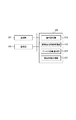
101はLAN(Local Area Network)、102は画像形成装置、103はProxy Server、104はセキュリティを高めるために設置されたFW(Firewall)を表している。画像形成装置102にはFAXやコピーなどの機能が含まれてもよい(図示しない)。105は一般のユーザが業務等で使用するパーソナルコンピュータ(PC)である。また、106は画像形成装置のデバイス情報の管理や保守のための処理を行うための管理サーバである。ここで、107はFWで保護されたローカル環境となり、例えば、管理サーバ106が管理する1つの顧客環境といえる。図示されるように顧客環境には、複数台の画像形成装置が設置されることが想定され、これら画像形成装置において障害などが発生した際には、管理サーバ106に通知され、サービスマンの手配などが行われることになる。画像形成装置102が、障害発生時や通信スケジュールに従って、自身の管理情報及び稼動情報などのデバイス情報をインターネット109経由で管理サーバ106へ送信する。なお、図示しないが、管理サーバ106は複数のこのような顧客環境と接続され、その環境内の画像形成装置を遠隔から管理する。
108は、画像形成装置に様々な機能を提供するための提供装置であり、画像形成装置102がインターネット109を介して利用可能な機能を備えている。例えば、画像形成装置102が連携することで利用可能な機能としては、大容量のストレージ機能、帳票作成アプリ、データの形式変換アプリ、及びワークフロー作成アプリなどを備える。画像形成装置102が提供装置108に備えられた機能を利用する場合は、インターネット109を介して提供装置108と通信を行い、提供装置108において所定の処理を行わせる。その後、画像形成装置102は、提供装置108から処理結果を受け取ることにより、ユーザに対し機能を提供する。
A providing
本実施例において、通信プロトコルは、HTTPやHTTPSなどのプロトコルを想定しているが、とくにそれに限定されるものではない。例えば、図1の例において、画像形成装置102はHTTPSを利用してProxy Server103とFW104を介して、管理サーバ106にデータを送信している。
In this embodiment, the communication protocol is assumed to be a protocol such as HTTP or HTTPS, but is not particularly limited thereto. For example, in the example of FIG. 1, the
図2は、管理サーバ106の内部の構成例を説明する図である。管理サーバ106は通信部201、HDDやROM、RAMなどを含む記憶部202、CPUなどの制御部203によって構成される。通信部201は画像形成装置102と通信を行う機能を持つ。画像形成装置102からのデバイス情報(カウンタ値、ログなどの稼働情報、およびハード障害やジャム多発等の障害情報)を受信したり、画像形成装置102へ必要な指示・設定情報などを送信したりする。カウンタ値とは画像形成装置で行われた印刷した枚数や部品の使用回数などを示す。記憶部202において、デバイス情報や販売会社情報、顧客情報などを保存する。制御部203は記憶部202に格納されるプログラムを実行することで、通知管理部204、販売会社情報管理部205、デバイス情報管理部206、顧客情報管理部207といった論理的な各モジュールによる処理を実現する。よって、制御部203により、後述されるような画像形成装置102の監視や、保守を行うために必要な情報の管理などが実現されることになる。
FIG. 2 is a diagram illustrating an internal configuration example of the
通知管理部204は、画像形成装置の監視などに必要な通知情報の生成や通知先の指定を行い、通信部204を介した通知制御を行う。通知には画像形成装置102を保守するサービスマンを手配するための保守依頼通知や、顧客環境への消耗品(カートリッジや消耗部品)の補充依頼通知などがある。販売会社情報管理部205は、顧客環境に設置された画像形成装置102のサポートを行う販売会社の情報を管理する。デバイス情報管理部206は、管理対象の画像形成装置102のデバイス情報を管理する。ここでは、画像形成装置の識別情報(IPアドレス、MACアドレス、及び機種情報など)、画像形成装置の状態情報、保守履歴、画像形成装置の管理者情報、画像形成装置の消耗品管理情報などを管理する。顧客情報管理部207は、画像形成装置102が設置された顧客環境の情報を管理する。その情報の中には、販売会社との保守契約に関する情報や、顧客環境に設置された画像形成装置に対して機能を提供する提供装置の情報も含まれる。
The
図3は、画像形成装置102の内部の構成例を説明する図である。画像形成装置102は通信部301、HDDやROM、RAMなどを含む記憶部302、画像形成エンジンなどを含む画像形成部303、CPUなどの制御部304、操作部305、表示部306により構成されている。通信部301は、画像形成装置102のデバイス情報を管理サーバ106へ送信するといった外部との通信を行うためのものである。また、管理サーバ106から送信される指示などを受信する。また提供装置108と、所望の機能を要求して利用するための通信を行う。送受信には、SMTPやHTTP/HTTPSなどを用いられる。記憶部302は、デバイス情報、管理サーバ106の情報、提供装置108の情報などの情報を保持する。また、画像形成装置102における動作履歴や、発生したさまざまな異常や故障による障害情報なども記憶する。管理サーバ106の情報には管理サーバ106のIPアドレスなどの通信に必要なネットワーク情報などが含まれる。提供装置108の情報には、ネットワーク情報に加え、提供される機能に関する情報も含まれる。画像形成部303は印刷データを解釈して、印刷物を出力する機能を持つ。操作部305は、ユーザによる印刷指示をはじめとする画像形成装置102に対する操作指示を可能とするインターフェースである。表示部306はユーザに対して適切な情報を表示する。表示情報には画像形成装置の状態情報、設定情報などが含まれる。制御部304は画像形成装置102の通信処理や印刷処理など処理全体を制御する。また、操作部102などからの入力を受けて、装置内の設定変更などの処理を制御する。さらに、制御部304が所定のプログラムを実行することで、論理的なモジュールである管理部307による状態監視や障害情報などの管理や、管理サーバ106への通知制御などの処理を実現する。
FIG. 3 is a diagram illustrating an internal configuration example of the
図4は、管理サーバ106が管理する管理対象の画像形成装置の機種情報と提供装置108が提供する機能との対応テーブルの一例である。この対応テーブルにより、管理サーバ106は、提供装置108が提供する各機能を利用可能な画像形成装置の機種などを特定することができる。
FIG. 4 is an example of a correspondence table between model information of image forming apparatuses to be managed managed by the
401は、画像形成装置102の識別情報を示している。ここでは、識別情報として機種情報を例示する。402は、提供装置108が提供する機能を示す。機能とは、画像形成装置102でスキャンした文書を取得し保存するファイル管理機能や、インターネット上の文書を画像形成装置へ直接所望なデータ形式に変換して送信し印刷させるためのネットワークプリント機能などがある。また、画像形成装置でスキャンして得られたデータに所望な加工を施し外部に送信するといった定型業務を提供するためのワークフロー機能も例示している。
なお、以降に説明するものも含め、管理サーバ106が管理するテーブルは、管理サーバ106の記憶部202に保持されていても、管理サーバ106が参照可能なストレージを備える外部装置が保持していてもよい。また、管理テーブルの構成も同様なデータ管理が行えるのであれば、とくにその形式は限定されない。例えば、本実施例の管理テーブルを複数のテーブルに分割して構成してもよい。
It should be noted that the tables managed by the
図5は、管理サーバ106が管理する、提供装置108が提供する機能と、その機能を利用可能な画像形成装置のファームウェアのバージョン情報との対応テーブルの一例である。
FIG. 5 is an example of a correspondence table of functions provided by the providing
501は、画像形成装置102のファームウェア情報である。502は、提供装置108が提供する機能を示す。このテーブルにより管理サーバ106は、提供装置108が提供する機能を利用するのに必要な画像形成装置のファームウェアバージョンを特定することができる。
図6は、管理サーバ106が管理する障害情報テーブルの一例である。601は、画像形成装置で発生する障害を特定するためのコードを示す。このコードを含む通知を用いて、画像形成装置は管理サーバ106に対して異常や故障の発生を通知することになる。602は、各障害の障害内容を示す。また、図示されていないが各障害コードには重要度などを付与してもよい。管理サーバ106は、この障害情報テーブルを参照して、障害の種類の特定し、その内容や重要度に応じてサービスマンの手配のための通知などを行うことになる。
FIG. 6 is an example of a failure information table managed by the
図7は、管理サーバ106が管理する通知先情報に関するテーブルの一例である。701は、画像形成装置の販売会社に所属する保守担当者の氏名を示す。保守担当者とは顧客先へ訪問し、保守サービスを行うサービスマンや、電話対応を行うオペレータなどを意味する。保守担当者の情報は、管理サーバ106が管理する販売会社情報や顧客情報などにIDをもとに対応付けて管理される。対応付く顧客などに対して保守担当者によるサービスが提供されることになる。702は、各保守担当者の通知先の情報(メールアドレス)を示す。本テーブルにより、管理サーバ106は、画像形成装置106で発生した故障などの復旧のために保守担当者に対して、障害情報の通知などが行える。703は、提供装置108の保守を担当する担当者の通知先の情報を示している。
FIG. 7 is an example of a table related to notification destination information managed by the
なお、本実施例において、管理サーバ106は画像形成装置102を主にネットワークを介して保守などのために遠隔から管理を行うことになる。また、画像形成装置に機能を提供する提供装置108に関しても、必要な情報を管理しておくことで、効率的な画像形成装置の管理を行うことが可能となる。
In this embodiment, the
図8は、画像形成装置102における、管理サーバ106への障害情報の通知に関する処理の一例を示したフローチャートである。
FIG. 8 is a flowchart illustrating an example of processing related to notification of failure information to the
S801で、管理部107が、画像形成装置102内の不図示のセンサなどで認識された異常などの障害の発生を検知する。S802で、管理部107が、障害が発生した際に、提供装置108が提供する機能を利用していたかどうかを判断する。S802で、提供装置108の機能を利用していたと判断された場合はS803に、利用していないと判断された場合はS806に進む。
In step S <b> 801, the
S803で、管理部107が、障害の内容から、障害の発生が提供装置108に原因があるかを判断する。例えば、画像形成装置102上で利用されていた機能がエラー終了した場合であって、提供装置108側から通信が遮断された際には、提供装置108側に障害の原因があると判断できる。また、ネットワークプリント機能を利用した場合に、提供装置108から送信された印刷データのフォーマットや記述内容に異常があったとする。具体的には、PDL(Page Description Language)の記述内容に異常があった場合などである。この場合には、画像形成装置102のレンダリング処理時に「PDLが解釈できない」ことなどが想定される。このような場合にも、提供装置108側に障害の原因があると判断できる。S803で、障害の発生が提供装置108に原因があると判断できた場合には、S804に進む。一方で、明らかに画像形成装置の内部で発生した障害(ジャムなど)が検出された際や、提供装置108側で発生したかを障害の内容からでは不明であった際には、障害の発生が提供装置108に原因があると判断できなかったとして、S806に進む。
In step S <b> 803, the
S806で、管理部107が、発生した障害に関する障害情報を作成する。ここで作成される障害情報には、画像形成装置102自身で発生した障害(ジャムなど)の内容を示す障害コードが含まれる。また、障害の発生が提供装置108に原因があると判断できなかった場合(S803NO)であっても、S801で発生が検出された障害(通信エラーや処理の異常終了など)を示す障害コード及び提供装置108を利用している際に発生した障害であることを示す情報を含む障害情報を作成することになる。
In step S806, the
一方、S804では、管理部107が、障害の発生が提供装置108に原因があることが識別可能な障害情報を作成する。例えば、前述したPDLエラーでは、予め用意されているレンダリングエラー(取得したPDLが異常)を示す障害コード「x20003」を含む障害情報が作成される。また、このステップにおいては、S801で検出した障害のために画像形成装置用に定義されている障害コードと、障害の発生が提供装置108に原因があることを識別できる識別子とを含ませて障害情報の作成してもよい。また、提供装置108より、提供装置108で発生した異常などを示す情報を受信した場合は、その情報を含めた障害情報を作成してもよい。
On the other hand, in step S <b> 804, the
S805で、管理部107が、S804、またはS806で作成した自装置の識別情報とともに障害情報を管理サーバ106へ送信する。その後、本処理は終了する。
In step S805, the
図9は、管理サーバ106が画像形成装置102から障害情報を受信した際の処理の一例を示したフローチャートである。
FIG. 9 is a flowchart illustrating an example of processing when the
S901で、通知管理部204は、画像形成装置102からの障害情報を受信し、記憶部202に記憶する制御を行う。障害情報は、画像形成装置の識別情報(IPアドレスや機種情報)とともに受信され、記憶部202に対応付けて記憶され、デバイス情報管理部206により管理される。
In step S <b> 901, the
S902で、通知管理部204は、図6の障害情報テーブルを参照する。そして、受信した障害情報に含まれる障害コードに基づき、画像形成装置102に原因のある障害であるかどうか判断する。S902で画像形成装置102に原因のある障害であると判断された場合にはS907に進み、画像形成装置102に原因のある障害であると判断されなかった場合にはS903に進む。S903で、通知管理部204は、図6の障害情報テーブルを参照し、受信した障害情報が提供装置108に原因がある障害であるかどうか判断する。提供装置108に原因がある障害、つまりS804で作成された障害情報で示すであると判断された場合にはS906に進み、そうでない場合にはS904に進む。
In step S902, the
S904で、通知管理部204は、デバイス情報と提供装置108の情報から原因を分析する。具体的には図4、図5の対応テーブルから障害情報を送信してきた画像形成装置102の機種は提供装置108の機能を利用可能であるか、また、画像形成装置102のファームウェアバージョンが機能を利用する上での基準に達しているかなどを確認する。例えば、S901で受信した障害情報に提供装置108を利用している際に発生した障害であることを示す情報を含まれ、上記確認の結果、画像形成装置102が提供装置108を利用可能だった場合、提供装置108側の保守担当員に連絡すべきと分析される。S904の分析を踏まえて、S905で管理サーバ106は提供装置108側の担当に通知が必要な障害であるかどうか判断する。S905で判断した結果、提供装置108側の担当に通知が必要な障害であると判断した場合、S906で管理サーバは提供装置108の保守担当者へ通知し、処理終了となる。S905で判断した結果、提供装置108の障害でないと判断した場合、S907に進む。
In step S <b> 904, the
S907で、通知管理部204は、画像形成装置102の保守担当者に対して障害の発生を通知する。通知先に関しては、障害情報を送信してきた画像形成装置の識別情報をもとに図7の通知先情報テーブルを参照することで決定される。保守担当者への通知は、障害コードを含ませるのなどして、障害の発生とその内容を確認できる通知とする。この通知により、画像形成装置に原因があるであろう障害の復旧のためにサービスマンの手配などが行われることになる。
In step S907, the
ここで、提供装置108の保守担当者に対して障害の発生を通知する(S906)際の通知先に関しては、障害情報を送信してきた画像形成装置の識別情報をもとに図7の通知先情報テーブルを参照することで決定される。保守担当者への通知は、障害コードを含ませるなどして、障害の発生とその内容を確認できる通知とする。この通知により、少なくとも提供装置108に原因があると特定できる障害に関しては、適切に提供装置108の保守担当者に連絡できる。また、画像形成装置から送信されてきた障害情報であっても、明らかに無駄となるであろう画像形成装置の保守を担当するサービスマンの手配などを抑制できる。
Here, regarding the notification destination when notifying the maintenance staff of the providing
本実施例では、提供装置108側に障害の原因がある場合には、とくに画像形成装置側の保守担当者には通知を行ってはいない。しかしながら、S906において、画像形成装置側の保守担当者に対しても提供装置108側に原因がある障害が発生している旨の通知を行ってもよい。これにより、画像形成装置側の保守担当者は、画像形成装置から受信した障害情報のすべてをその原因を含めて、きめ細かく管理できるようになる。
In the present embodiment, when there is a cause of failure on the providing
(実施例2)
実施例1では、画像形成装置が装置内で発生を検知した障害、提供装置108から通知された障害などを管理サーバに通知した際の処理について説明した。しかしながら、それ以外にも画像形成装置に対して、管理サーバの提供する機能に基づきサービスマンなどを手配する場合がある。具体的には、ユーザが感じた不具合や、画像形成などに直接関与しない外部部品の故障(移動用のキャスターの破損)などを、ユーザの手動入力に応じて管理サーバに通知するための入力手段が画像形成装置の操作部305に用意されている。この通知を管理サーバが受けた場合は、サービスマンを手配するための処理が行われることになる。なお、この通知を本実施例では、画像形成装置からの修理依頼と呼ぶ。また、修理依頼で対象となる障害はユーザの判断で障害と認識されたものであって、修理依頼であることを示す障害コードと、ユーザが修理依頼時に操作部305から入力した追加情報が画像形成装置から管理サーバに通知されるものとする。
(Example 2)
In the first embodiment, the processing when the image forming apparatus notifies the management server of a failure detected in the apparatus, a failure notified from the providing
本実施例においては、基本的には、図8、9と同様の処理が画像形成装置、管理サーバにおいて行われる。具体的には、図8のS801での障害発生の検知が、修理依頼のユーザによる入力を検知に置換され、以降、その修理依頼に関して同様の処理が行われる。なお、S803で提供装置側に原因であることを追加情報として入力されている場合は、S806に進むといった処理になる。図9では、修理依頼に関する通知先を、提供装置の機能を利用中か否かの判定、追加情報の内容などに応じて、切り換えることになる。 In the present embodiment, basically, the same processing as in FIGS. 8 and 9 is performed in the image forming apparatus and the management server. Specifically, the detection of the failure occurrence in S801 in FIG. 8 is replaced with the detection by the user of the repair request, and thereafter the same processing is performed regarding the repair request. In S803, if the cause is input as additional information to the providing apparatus side, the process proceeds to S806. In FIG. 9, the notification destination regarding the repair request is switched depending on whether or not the function of the providing device is being used, the content of the additional information, and the like.
Claims (12)
前記画像形成装置は、
ネットワークを介して提供装置と通信を行い、提供装置が提供する機能を利用することが可能であって、
前記提供装置が提供する機能を利用しているときに前記画像形成装置で障害が検知された場合に、当該検知された障害の原因が提供装置にあるかを判断する判断手段と、
前記判断手段により障害の原因が提供装置にあると判断された場合には提供装置に原因があると特定できる障害情報を作成し、前記判断手段により障害の原因が提供装置にあると判断されなかった場合には画像形成装置で検知された障害に関する障害情報を作成する作成手段と、
前記作成手段により作成された障害情報を前記管理サーバに送信する送信手段と、を有し、
前記管理サーバは、
前記画像形成装置から障害情報を受信する受信手段と、
前記受信した障害情報に基づき障害の原因が、前記画像形成装置にあるか、前記提供装置にあるかを特定する特定手段と、
前記特定手段により、前記受信した障害情報から、障害の原因が前記画像形成装置にあるか、前記提供装置にあるかを特定できなかった場合に、前記画像形成装置のデバイス情報の分析を行う分析手段と、
前記特定手段により前記画像形成装置から受信した障害情報に基づき前記画像形成装置に障害の原因があると特定できた場合には、前記画像形成装置の保守のための手配を行うための通知を行う通知手段と、を有し、
前記画像形成装置の前記作成手段は、前記提供装置が提供する機能を利用していないときに前記画像形成装置で障害が検知された場合には、当該検知された障害に基づき、前記画像形成装置に関する障害情報を作成し、
前記管理サーバは、前記特定手段により前記画像形成装置から受信した障害情報に基づき前記提供装置に障害の原因があると特定できる場合、及び、前記分析手段により前記提供装置の保守を要することを分析した場合には、前記画像形成装置の保守のための手配を行わないことを特徴とする管理システム。 A management system including an image forming apparatus and a management server that communicates with the image forming apparatus via a network,
The image forming apparatus includes:
It is possible to communicate with a providing device via a network and use a function provided by the providing device,
A determination unit configured to determine whether the cause of the detected failure is in the providing apparatus when a failure is detected in the image forming apparatus when using the function provided by the providing apparatus;
When it is determined by the determining means that the cause of the failure is in the providing device, failure information that can identify that the providing device has the cause is created, and the determining device does not determine that the cause of the failure is in the providing device Creating means for creating failure information related to a failure detected by the image forming apparatus,
Anda transmitting means for transmitting to said management server fault information created by the creation means,
The management server
Receiving means for receiving fault information from the image forming apparatus;
Identifying means for identifying whether the cause of the fault is in the image forming apparatus or the providing apparatus based on the received fault information;
Analysis for analyzing device information of the image forming apparatus when the specifying unit cannot determine whether the cause of the failure is in the image forming apparatus or the providing apparatus from the received failure information Means,
When it is possible to identify that the cause of the image forming apparatus has a failure based on the failure information received from the image forming apparatus by the specifying unit, a notification for making arrangements for maintenance of the image forming apparatus is performed. has a notification means, the,
In the case where a failure is detected in the image forming apparatus when the function provided by the providing device is not used, the creating unit of the image forming apparatus is configured to use the image forming apparatus based on the detected failure. Create fault information about
The management server analyzes that the providing device can identify that there is a cause of the failure based on the failure information received from the image forming device by the specifying device, and that the analyzing device needs maintenance of the providing device. In this case, the management system does not make arrangements for maintenance of the image forming apparatus.
前記画像形成装置はネットワークを介して提供装置と通信を行い、提供装置が提供する機能を利用することが可能であって、
前記提供装置が提供する機能を利用しているときに前記画像形成装置で障害が検知された場合に、当該画像形成装置で検知された障害の原因が提供装置にあるかを判断する判断工程と、
前記判断工程で障害の原因が提供装置にあると判断された場合には提供装置に原因があると特定できる障害情報を作成し、前記判断工程で障害の原因が提供装置にあると判断されなかった場合には画像形成装置で検知された障害に関する障害情報を作成する作成工程と、
前記作成された障害情報を前記管理サーバに送信する送信工程と、を有し、
前記管理サーバは、
前記画像形成装置から障害情報を受信する受信工程と、
前記受信した障害情報に基づき障害の原因が、前記画像形成装置にあるか、前記提供装置にあるかを特定する特定工程と、
前記特定工程で、前記受信した障害情報から、障害の原因が前記画像形成装置にあるか、前記提供装置にあるかを特定できなかった場合に、前記画像形成装置のデバイス情報の分析を行う分析工程と、
前記特定工程で前記画像形成装置から受信した障害情報に基づき前記画像形成装置に障害の原因があると特定できた場合には、前記画像形成装置の保守のための手配を行うための通知を行う通知工程と、を有し、
前記画像形成装置の前記作成工程では、前記提供装置が提供する機能を利用していないときに前記画像形成装置で障害が検知された場合には、当該検知された障害に基づき、前記画像形成装置に関する障害情報が作成され、
前記管理サーバは、前記特定工程で前記画像形成装置から受信した障害情報に基づき前記提供装置に障害の原因があると特定できた場合、及び、前記分析工程で前記提供装置の保守を要することを分析した場合には、前記画像形成装置の保守のための手配を行わないことを特徴とする方法。 A method in a management system including an image forming apparatus and a management server that communicates with the image forming apparatus via a network,
The image forming apparatus communicates with a providing apparatus via a network and can use a function provided by the providing apparatus,
A determination step of determining whether the cause of the failure detected by the image forming apparatus is in the providing apparatus when a failure is detected by the image forming apparatus when using the function provided by the providing apparatus; ,
When it is determined in the determination step that the cause of the failure is in the providing device, failure information that can be identified as the cause in the providing device is created, and in the determination step, it is not determined that the cause of the failure is in the providing device A creation process for creating failure information regarding failures detected by the image forming apparatus,
Anda transmission step of transmitting the created failure information to the management server,
The management server
A receiving step of receiving failure information from the image forming apparatus;
A specifying step for identifying whether the cause of the fault is in the image forming apparatus or the providing apparatus based on the received fault information;
Analysis for analyzing device information of the image forming apparatus when it is not possible to identify whether the cause of the failure is in the image forming apparatus or the providing apparatus from the received failure information in the specifying step Process,
If it is possible to identify that there is a cause of a failure in the image forming apparatus based on the failure information received from the image forming apparatus in the specifying step, a notification for making arrangements for maintenance of the image forming apparatus is performed. has a notification process, the,
In the creation step of the image forming apparatus, when a failure is detected in the image forming apparatus when the function provided by the providing apparatus is not used, the image forming apparatus is based on the detected failure. Failure information about
The management server needs to maintain the providing apparatus in the analysis step when it is possible to identify the cause of the failure in the providing apparatus based on the failure information received from the image forming apparatus in the specifying step. If analyzed, no arrangement is made for maintenance of the image forming apparatus.
前記画像形成装置から障害情報を受信する受信手段と、
前記受信した障害情報に基づき障害の原因が、前記画像形成装置にあるか、前記提供装置にあるかを特定する特定手段と、
前記特定手段により、前記受信した障害情報から、障害の原因が前記画像形成装置にあるか、前記提供装置にあるかを特定できなかった場合に、前記画像形成装置のデバイス情報の分析を行う分析手段と、
前記特定手段により前記画像形成装置から受信した障害情報に基づき前記画像形成装置に障害の原因があると特定できた場合には、前記画像形成装置の保守のための手配を行うための通知を行う通知手段と、を有し、
前記特定手段により前記画像形成装置から受信した障害情報に基づき前記提供装置に障害の原因があると特定できる場合、及び、前記分析手段により前記提供装置の保守を要することを分析した場合には、前記画像形成装置の保守のための手配を行わないことを特徴とする管理サーバ。 A management server for managing an image forming apparatus capable of communicating with a providing apparatus via a network and using a function provided by the providing apparatus;
Receiving means for receiving fault information from the image forming apparatus;
Identifying means for identifying whether the cause of the fault is in the image forming apparatus or the providing apparatus based on the received fault information;
Analysis for analyzing device information of the image forming apparatus when the specifying unit cannot determine whether the cause of the failure is in the image forming apparatus or the providing apparatus from the received failure information Means,
When it is possible to identify that the cause of the image forming apparatus has a failure based on the failure information received from the image forming apparatus by the specifying unit, a notification for making arrangements for maintenance of the image forming apparatus is performed. has a notification means, the,
When it is possible to identify the cause of the failure in the providing device based on the failure information received from the image forming device by the specifying unit, and when analyzing that the providing device requires maintenance, management server, characterized in that it is performed to arrange for maintenance of the image forming apparatus.
前記受信した障害情報に基づき提供装置に障害の原因があると特定できる場合には画像形成装置の保守のための手配を行うことなく、前記通知手段は前記管理手段に管理される前記提供装置の保守を行う担当への通知先に対して障害の発生を通知することを特徴とする請求項3または4に記載の管理サーバ。 Management means for managing a notification destination to a person in charge of maintenance of the providing device;
When it is possible to identify that the cause of the failure is in the providing device based on the received failure information, the notifying unit manages the maintenance of the image forming device without making arrangements for the maintenance of the image forming device. 5. The management server according to claim 3, wherein the occurrence of a failure is notified to a notification destination for a person in charge of maintenance.
前記通知手段は、当該画像形成装置で提供装置の提供する機能が利用できると分析された場合には、前記管理手段に管理される前記提供装置の保守を行う担当への通知先に対して障害の発生を通知することを特徴とする請求項5に記載の管理サーバ。 The analysis means analyzes whether the function provided by the providing apparatus can be used in the image forming apparatus based on device information including at least one of the model and firmware information of the image forming apparatus,
When it is analyzed that the function provided by the providing device can be used in the image forming apparatus , the notifying unit has a problem with a notification destination for a person who performs maintenance of the providing device managed by the managing unit. The management server according to claim 5, wherein the occurrence of the occurrence is notified.
前記画像形成装置から障害情報を受信する受信工程と、
前記受信した障害情報に基づき障害の原因が、前記画像形成装置にあるか、前記提供装置にあるかを特定する特定工程と、
前記特定工程で、前記受信した障害情報から、障害の原因が前記画像形成装置にあるか、前記提供装置にあるかを特定できなかった場合に、前記画像形成装置のデバイス情報の分析を行う分析工程と、
前記特定工程で前記画像形成装置から受信した障害情報に基づき前記画像形成装置に障害の原因があると特定できた場合には、前記画像形成装置の保守のための手配を行うための通知を行う通知工程と、を有し、
前記特定工程で前記画像形成装置から受信した障害情報に基づき前記提供装置に障害の原因があると特定できた場合、及び、前記分析工程で前記提供装置の保守を要することを分析した場合には、前記画像形成装置の保守のための手配を行わないことを特徴とする方法。 A method in a management server for managing an image forming apparatus capable of communicating with a providing apparatus via a network and using a function provided by the providing apparatus,
A receiving step of receiving failure information from the image forming apparatus;
A specifying step for identifying whether the cause of the fault is in the image forming apparatus or the providing apparatus based on the received fault information;
Analysis for analyzing device information of the image forming apparatus when it is not possible to identify whether the cause of the failure is in the image forming apparatus or the providing apparatus from the received failure information in the specifying step Process,
If it is possible to identify that there is a cause of a failure in the image forming apparatus based on the failure information received from the image forming apparatus in the specifying step, a notification for making arrangements for maintenance of the image forming apparatus is performed. has a notification process, the,
When it has been determined that there is a cause of a failure in the providing device based on the failure information received from the image forming device in the specifying step, and when it is analyzed that the providing device needs to be maintained in the analyzing step The method for arranging maintenance for the image forming apparatus is not performed.
ネットワークを介して提供装置と通信を行い、提供装置が提供する機能を利用することが可能であって、
前記提供装置が提供する機能を利用しているときに前記画像形成装置で障害が検知された場合に、当該検知された障害の原因が提供装置にあるかを判断する判断手段と、
前記判断手段により障害の原因が提供装置にあると判断された場合には提供装置に原因があると特定できる障害情報を作成し、前記判断手段により障害の原因が提供装置にあると判断されなかった場合には画像形成装置で検知された障害に関する障害情報を作成する作成手段と、
前記作成手段により作成された障害情報を前記管理サーバに送信する送信手段と、を有し、
前記作成手段は、前記提供装置が提供する機能を利用していないときに前記画像形成装置で障害が検知された場合には、当該検知された障害に基づき、前記画像形成装置に関する障害情報を作成することを特徴とする画像形成装置。 An image forming apparatus that communicates with a management server via a network,
It is possible to communicate with a providing device via a network and use a function provided by the providing device,
A determination unit configured to determine whether the cause of the detected failure is in the providing apparatus when a failure is detected in the image forming apparatus when using the function provided by the providing apparatus;
When it is determined by the determining means that the cause of the failure is in the providing device, failure information that can identify that the providing device has the cause is created, and the determining device does not determine that the cause of the failure is in the providing device Creating means for creating failure information related to a failure detected by the image forming apparatus,
Transmission means for transmitting the failure information created by the creation means to the management server ,
If the image forming apparatus detects a failure when the function provided by the providing device is not used, the creating unit creates failure information regarding the image forming device based on the detected failure. An image forming apparatus.
ネットワークを介して提供装置と通信を行い、提供装置が提供する機能を利用することが可能であって、
前記提供装置が提供する機能を利用しているときに前記画像形成装置で障害が検知された場合に、当該検知された障害の原因が提供装置にあるかを判断する判断工程と、
前記判断工程で障害の原因が提供装置にあると判断された場合には提供装置に原因があると特定できる障害情報を作成し、前記判断工程で障害の原因が提供装置にあると判断されなかった場合には画像形成装置で検知された障害に関する障害情報を作成する作成工程と、
前記作成された障害情報を前記管理サーバに送信する送信工程と、を有し、
前記作成工程では、前記提供装置が提供する機能を利用していないときに前記画像形成装置で障害が検知された場合には、当該検知された障害に基づき、前記画像形成装置に関する障害情報が作成されることを特徴とする方法。 A method in an image forming apparatus that communicates with a management server via a network,
It is possible to communicate with a providing device via a network and use a function provided by the providing device,
A determination step of determining whether a cause of the detected failure is in the providing device when a failure is detected in the image forming apparatus when using the function provided by the providing device;
When it is determined in the determination step that the cause of the failure is in the providing device, failure information that can be identified as the cause in the providing device is created, and in the determination step, it is not determined that the cause of the failure is in the providing device A creation process for creating failure information regarding failures detected by the image forming apparatus,
A transmission step of transmitting the created failure information to the management server ,
In the creation step, when a failure is detected in the image forming apparatus when the function provided by the providing apparatus is not used, failure information regarding the image forming apparatus is created based on the detected failure. It is wherein the Rukoto.
Priority Applications (3)
| Application Number | Priority Date | Filing Date | Title |
|---|---|---|---|
| JP2010134309A JP5676931B2 (en) | 2010-06-11 | 2010-06-11 | Management system and method |
| US13/157,226 US8994989B2 (en) | 2010-06-11 | 2011-06-09 | Management system and method therefor |
| US14/659,356 US9218143B2 (en) | 2010-06-11 | 2015-03-16 | Management system and method for an image forming apparatus configured to identify and report failures related to forming an image |
Applications Claiming Priority (1)
| Application Number | Priority Date | Filing Date | Title |
|---|---|---|---|
| JP2010134309A JP5676931B2 (en) | 2010-06-11 | 2010-06-11 | Management system and method |
Publications (3)
| Publication Number | Publication Date |
|---|---|
| JP2011258135A JP2011258135A (en) | 2011-12-22 |
| JP2011258135A5 JP2011258135A5 (en) | 2013-07-18 |
| JP5676931B2 true JP5676931B2 (en) | 2015-02-25 |
Family
ID=45096023
Family Applications (1)
| Application Number | Title | Priority Date | Filing Date |
|---|---|---|---|
| JP2010134309A Active JP5676931B2 (en) | 2010-06-11 | 2010-06-11 | Management system and method |
Country Status (2)
| Country | Link |
|---|---|
| US (2) | US8994989B2 (en) |
| JP (1) | JP5676931B2 (en) |
Families Citing this family (4)
| Publication number | Priority date | Publication date | Assignee | Title |
|---|---|---|---|---|
| JP5639484B2 (en) * | 2011-01-14 | 2014-12-10 | キヤノン株式会社 | Management system, management server, image forming apparatus, management method, and program |
| JP6187053B2 (en) | 2012-09-18 | 2017-08-30 | 株式会社リコー | Information processing system, information processing apparatus, and program |
| CN107846525B (en) * | 2016-09-19 | 2021-09-14 | 冲电气工业株式会社 | Management server, image processing apparatus, terminal apparatus, and management method of image processing system |
| JP7046648B2 (en) * | 2018-02-27 | 2022-04-04 | キヤノン株式会社 | Print processing system, method, and program |
Family Cites Families (8)
| Publication number | Priority date | Publication date | Assignee | Title |
|---|---|---|---|---|
| JPH07230372A (en) * | 1993-12-24 | 1995-08-29 | Hitachi Ltd | Print system |
| JP2002157171A (en) * | 2000-11-17 | 2002-05-31 | Canon Inc | Information processing device, equipment management program, storage medium storing it, and method of managing equipment |
| JP4265250B2 (en) * | 2003-03-24 | 2009-05-20 | 富士ゼロックス株式会社 | Data processing system and program |
| JP2008210103A (en) * | 2007-02-26 | 2008-09-11 | Ricoh Co Ltd | Document processing system, document processing method and program |
| JP4863386B2 (en) * | 2007-04-06 | 2012-01-25 | シャープ株式会社 | Image processing apparatus and information transmission method in the image processing apparatus |
| JP2009206788A (en) * | 2008-02-27 | 2009-09-10 | Canon Inc | Management server, image forming apparatus, management method, and program |
| JP5300332B2 (en) * | 2008-06-04 | 2013-09-25 | キヤノン株式会社 | Network device, workflow processing system, and workflow processing method |
| JP4600550B2 (en) * | 2008-08-29 | 2010-12-15 | コニカミノルタビジネステクノロジーズ株式会社 | Image processing apparatus, job execution method and job execution program in the same |
-
2010
- 2010-06-11 JP JP2010134309A patent/JP5676931B2/en active Active
-
2011
- 2011-06-09 US US13/157,226 patent/US8994989B2/en active Active
-
2015
- 2015-03-16 US US14/659,356 patent/US9218143B2/en not_active Expired - Fee Related
Also Published As
| Publication number | Publication date |
|---|---|
| US20110304884A1 (en) | 2011-12-15 |
| US20150193174A1 (en) | 2015-07-09 |
| US9218143B2 (en) | 2015-12-22 |
| US8994989B2 (en) | 2015-03-31 |
| JP2011258135A (en) | 2011-12-22 |
Similar Documents
| Publication | Publication Date | Title |
|---|---|---|
| US10509606B2 (en) | Image forming apparatus retrieving error screen from web server | |
| JP5482530B2 (en) | Device management system, device management apparatus, and device management method | |
| JP5639484B2 (en) | Management system, management server, image forming apparatus, management method, and program | |
| JP5721659B2 (en) | Management device, management system, and control method | |
| JP5843586B2 (en) | Management system, image forming apparatus, and method thereof | |
| JP5413203B2 (en) | Device management system, device management apparatus, and device management method | |
| US8606902B2 (en) | Device management apparatus, device management system, device management method and medium | |
| JP2009206788A (en) | Management server, image forming apparatus, management method, and program | |
| JP2010200298A (en) | Management server, management method, monitoring device, control method of monitoring device, and program | |
| JP2011164862A (en) | Management system, monitoring apparatus and information processing method | |
| US9218143B2 (en) | Management system and method for an image forming apparatus configured to identify and report failures related to forming an image | |
| JP2008147941A (en) | Monitoring apparatus, image forming apparatus, monitoring system, method of changing network setting, and program | |
| JP5955070B2 (en) | Management system, management server, and method | |
| JP5615144B2 (en) | PRINT SYSTEM, IMAGE FORMING DEVICE, SERVER, PRINTING METHOD, AND PROGRAM | |
| CN103067640B (en) | Image forming apparatus and method | |
| EP2608520B1 (en) | Performing error notification and error recovery in an image forming apparatus | |
| JP6368157B2 (en) | Communication system and control method thereof | |
| JP2013182130A (en) | Automatic ordering system of image processing device component | |
| JP2013062599A (en) | Image forming apparatus, information processing method, and program | |
| JP7214450B2 (en) | Image processing device, image processing device control method, and program | |
| JP2013161460A (en) | Management system, monitoring device, and information processing method | |
| JP2005271406A (en) | Information processor, remote maintenance system, and program | |
| JP6025515B2 (en) | Device management system, management server, and control method thereof. | |
| JP2008065788A (en) | Image forming apparatus, image forming method, program and recording medium | |
| KR20220086902A (en) | Integrated management system for office equipments |
Legal Events
| Date | Code | Title | Description |
|---|---|---|---|
| A521 | Written amendment |
Free format text: JAPANESE INTERMEDIATE CODE: A523 Effective date: 20130530 |
|
| A621 | Written request for application examination |
Free format text: JAPANESE INTERMEDIATE CODE: A621 Effective date: 20130530 |
|
| A977 | Report on retrieval |
Free format text: JAPANESE INTERMEDIATE CODE: A971007 Effective date: 20140228 |
|
| A131 | Notification of reasons for refusal |
Free format text: JAPANESE INTERMEDIATE CODE: A131 Effective date: 20140401 |
|
| A521 | Written amendment |
Free format text: JAPANESE INTERMEDIATE CODE: A523 Effective date: 20140602 |
|
| TRDD | Decision of grant or rejection written | ||
| A01 | Written decision to grant a patent or to grant a registration (utility model) |
Free format text: JAPANESE INTERMEDIATE CODE: A01 Effective date: 20141202 |
|
| A61 | First payment of annual fees (during grant procedure) |
Free format text: JAPANESE INTERMEDIATE CODE: A61 Effective date: 20141226 |
|
| R151 | Written notification of patent or utility model registration |
Ref document number: 5676931 Country of ref document: JP Free format text: JAPANESE INTERMEDIATE CODE: R151 |