JP5672917B2 - Vehicle control device - Google Patents
Vehicle control device Download PDFInfo
- Publication number
- JP5672917B2 JP5672917B2 JP2010222222A JP2010222222A JP5672917B2 JP 5672917 B2 JP5672917 B2 JP 5672917B2 JP 2010222222 A JP2010222222 A JP 2010222222A JP 2010222222 A JP2010222222 A JP 2010222222A JP 5672917 B2 JP5672917 B2 JP 5672917B2
- Authority
- JP
- Japan
- Prior art keywords
- engine
- vehicle
- stop
- time
- tes
- Prior art date
- Legal status (The legal status is an assumption and is not a legal conclusion. Google has not performed a legal analysis and makes no representation as to the accuracy of the status listed.)
- Expired - Fee Related
Links
- 230000001133 acceleration Effects 0.000 claims description 134
- 239000000446 fuel Substances 0.000 claims description 99
- 238000001514 detection method Methods 0.000 claims description 14
- 238000000034 method Methods 0.000 description 15
- 230000008569 process Effects 0.000 description 14
- 230000005540 biological transmission Effects 0.000 description 11
- 230000005484 gravity Effects 0.000 description 11
- 230000000694 effects Effects 0.000 description 10
- 230000007423 decrease Effects 0.000 description 9
- 230000006870 function Effects 0.000 description 8
- 230000006872 improvement Effects 0.000 description 7
- 239000012530 fluid Substances 0.000 description 6
- 238000002347 injection Methods 0.000 description 4
- 239000007924 injection Substances 0.000 description 4
- 230000002265 prevention Effects 0.000 description 4
- 230000037396 body weight Effects 0.000 description 3
- 230000008859 change Effects 0.000 description 2
- 238000006243 chemical reaction Methods 0.000 description 2
- 230000003247 decreasing effect Effects 0.000 description 2
- 230000000881 depressing effect Effects 0.000 description 2
- 238000010586 diagram Methods 0.000 description 2
- 230000007246 mechanism Effects 0.000 description 2
- 230000009471 action Effects 0.000 description 1
- 230000009194 climbing Effects 0.000 description 1
- 238000002485 combustion reaction Methods 0.000 description 1
- 238000004891 communication Methods 0.000 description 1
- 230000000052 comparative effect Effects 0.000 description 1
- 230000008878 coupling Effects 0.000 description 1
- 238000010168 coupling process Methods 0.000 description 1
- 238000005859 coupling reaction Methods 0.000 description 1
- 230000000994 depressogenic effect Effects 0.000 description 1
- 230000008034 disappearance Effects 0.000 description 1
- 230000007613 environmental effect Effects 0.000 description 1
- 230000001105 regulatory effect Effects 0.000 description 1
- 238000005096 rolling process Methods 0.000 description 1
- 230000007704 transition Effects 0.000 description 1
Images


Classifications
-
- F—MECHANICAL ENGINEERING; LIGHTING; HEATING; WEAPONS; BLASTING
- F02—COMBUSTION ENGINES; HOT-GAS OR COMBUSTION-PRODUCT ENGINE PLANTS
- F02D—CONTROLLING COMBUSTION ENGINES
- F02D29/00—Controlling engines, such controlling being peculiar to the devices driven thereby, the devices being other than parts or accessories essential to engine operation, e.g. controlling of engines by signals external thereto
- F02D29/02—Controlling engines, such controlling being peculiar to the devices driven thereby, the devices being other than parts or accessories essential to engine operation, e.g. controlling of engines by signals external thereto peculiar to engines driving vehicles; peculiar to engines driving variable pitch propellers
-
- B—PERFORMING OPERATIONS; TRANSPORTING
- B60—VEHICLES IN GENERAL
- B60W—CONJOINT CONTROL OF VEHICLE SUB-UNITS OF DIFFERENT TYPE OR DIFFERENT FUNCTION; CONTROL SYSTEMS SPECIALLY ADAPTED FOR HYBRID VEHICLES; ROAD VEHICLE DRIVE CONTROL SYSTEMS FOR PURPOSES NOT RELATED TO THE CONTROL OF A PARTICULAR SUB-UNIT
- B60W10/00—Conjoint control of vehicle sub-units of different type or different function
- B60W10/04—Conjoint control of vehicle sub-units of different type or different function including control of propulsion units
- B60W10/06—Conjoint control of vehicle sub-units of different type or different function including control of propulsion units including control of combustion engines
-
- B—PERFORMING OPERATIONS; TRANSPORTING
- B60—VEHICLES IN GENERAL
- B60W—CONJOINT CONTROL OF VEHICLE SUB-UNITS OF DIFFERENT TYPE OR DIFFERENT FUNCTION; CONTROL SYSTEMS SPECIALLY ADAPTED FOR HYBRID VEHICLES; ROAD VEHICLE DRIVE CONTROL SYSTEMS FOR PURPOSES NOT RELATED TO THE CONTROL OF A PARTICULAR SUB-UNIT
- B60W30/00—Purposes of road vehicle drive control systems not related to the control of a particular sub-unit, e.g. of systems using conjoint control of vehicle sub-units
- B60W30/18—Propelling the vehicle
- B60W30/18009—Propelling the vehicle related to particular drive situations
- B60W30/18109—Braking
- B60W30/18118—Hill holding
-
- F—MECHANICAL ENGINEERING; LIGHTING; HEATING; WEAPONS; BLASTING
- F02—COMBUSTION ENGINES; HOT-GAS OR COMBUSTION-PRODUCT ENGINE PLANTS
- F02N—STARTING OF COMBUSTION ENGINES; STARTING AIDS FOR SUCH ENGINES, NOT OTHERWISE PROVIDED FOR
- F02N11/00—Starting of engines by means of electric motors
- F02N11/08—Circuits or control means specially adapted for starting of engines
- F02N11/0814—Circuits or control means specially adapted for starting of engines comprising means for controlling automatic idle-start-stop
- F02N11/0818—Conditions for starting or stopping the engine or for deactivating the idle-start-stop mode
- F02N11/0833—Vehicle conditions
- F02N11/0837—Environmental conditions thereof, e.g. traffic, weather or road conditions
-
- B—PERFORMING OPERATIONS; TRANSPORTING
- B60—VEHICLES IN GENERAL
- B60W—CONJOINT CONTROL OF VEHICLE SUB-UNITS OF DIFFERENT TYPE OR DIFFERENT FUNCTION; CONTROL SYSTEMS SPECIALLY ADAPTED FOR HYBRID VEHICLES; ROAD VEHICLE DRIVE CONTROL SYSTEMS FOR PURPOSES NOT RELATED TO THE CONTROL OF A PARTICULAR SUB-UNIT
- B60W2540/00—Input parameters relating to occupants
- B60W2540/12—Brake pedal position
-
- B—PERFORMING OPERATIONS; TRANSPORTING
- B60—VEHICLES IN GENERAL
- B60W—CONJOINT CONTROL OF VEHICLE SUB-UNITS OF DIFFERENT TYPE OR DIFFERENT FUNCTION; CONTROL SYSTEMS SPECIALLY ADAPTED FOR HYBRID VEHICLES; ROAD VEHICLE DRIVE CONTROL SYSTEMS FOR PURPOSES NOT RELATED TO THE CONTROL OF A PARTICULAR SUB-UNIT
- B60W2552/00—Input parameters relating to infrastructure
- B60W2552/15—Road slope, i.e. the inclination of a road segment in the longitudinal direction
-
- F—MECHANICAL ENGINEERING; LIGHTING; HEATING; WEAPONS; BLASTING
- F02—COMBUSTION ENGINES; HOT-GAS OR COMBUSTION-PRODUCT ENGINE PLANTS
- F02D—CONTROLLING COMBUSTION ENGINES
- F02D2200/00—Input parameters for engine control
- F02D2200/02—Input parameters for engine control the parameters being related to the engine
- F02D2200/06—Fuel or fuel supply system parameters
- F02D2200/0625—Fuel consumption, e.g. measured in fuel liters per 100 kms or miles per gallon
-
- F—MECHANICAL ENGINEERING; LIGHTING; HEATING; WEAPONS; BLASTING
- F02—COMBUSTION ENGINES; HOT-GAS OR COMBUSTION-PRODUCT ENGINE PLANTS
- F02N—STARTING OF COMBUSTION ENGINES; STARTING AIDS FOR SUCH ENGINES, NOT OTHERWISE PROVIDED FOR
- F02N11/00—Starting of engines by means of electric motors
- F02N11/10—Safety devices
-
- F—MECHANICAL ENGINEERING; LIGHTING; HEATING; WEAPONS; BLASTING
- F02—COMBUSTION ENGINES; HOT-GAS OR COMBUSTION-PRODUCT ENGINE PLANTS
- F02N—STARTING OF COMBUSTION ENGINES; STARTING AIDS FOR SUCH ENGINES, NOT OTHERWISE PROVIDED FOR
- F02N2200/00—Parameters used for control of starting apparatus
- F02N2200/12—Parameters used for control of starting apparatus said parameters being related to the vehicle exterior
- F02N2200/124—Information about road conditions, e.g. road inclination or surface
-
- Y—GENERAL TAGGING OF NEW TECHNOLOGICAL DEVELOPMENTS; GENERAL TAGGING OF CROSS-SECTIONAL TECHNOLOGIES SPANNING OVER SEVERAL SECTIONS OF THE IPC; TECHNICAL SUBJECTS COVERED BY FORMER USPC CROSS-REFERENCE ART COLLECTIONS [XRACs] AND DIGESTS
- Y02—TECHNOLOGIES OR APPLICATIONS FOR MITIGATION OR ADAPTATION AGAINST CLIMATE CHANGE
- Y02T—CLIMATE CHANGE MITIGATION TECHNOLOGIES RELATED TO TRANSPORTATION
- Y02T10/00—Road transport of goods or passengers
- Y02T10/10—Internal combustion engine [ICE] based vehicles
- Y02T10/40—Engine management systems
Landscapes
- Engineering & Computer Science (AREA)
- Chemical & Material Sciences (AREA)
- Combustion & Propulsion (AREA)
- Mechanical Engineering (AREA)
- General Engineering & Computer Science (AREA)
- Transportation (AREA)
- Automation & Control Theory (AREA)
- Health & Medical Sciences (AREA)
- Life Sciences & Earth Sciences (AREA)
- Atmospheric Sciences (AREA)
- Environmental & Geological Engineering (AREA)
- Toxicology (AREA)
- Control Of Vehicle Engines Or Engines For Specific Uses (AREA)
- Combined Controls Of Internal Combustion Engines (AREA)
Description
本発明は、エンジンの自動停止、自動再始動を行う車両の制御装置に関する。 The present invention relates to the control equipment of the vehicle performing automatic stop of the engine, the automatic restart.
周知のように、信号待ちのような停車中にエンジンを自動停止するとともに、運転者の発進操作に応じてエンジンを自動再始動することで、燃料消費の節約や排気エミッションの向上を図るエンジン自動停止再始動装置が実用されている。そして近年には、停車以前の車両の減速中からエンジンを停止させる装置も提案されている。 As is well known, the engine is automatically stopped while the vehicle is stopped, such as waiting for a signal, and the engine is automatically restarted according to the driver's starting operation, thereby saving fuel consumption and improving exhaust emission. Stop / restart devices are in practical use. In recent years, a device for stopping the engine while the vehicle is decelerating before stopping has been proposed.
そして従来、特許文献1に記載のように、ブレーキ踏み量が第1閾値X以上であることを条件にエンジンを自動停止し、ブレーキ踏み量が第2閾値Y以下であることを条件にエンジンを自動再始動するとともに、それら第1及び第2閾値を車速に応じて可変とする車両の制御装置が提案されている。 Conventionally, as described in Patent Document 1, the engine is automatically stopped on the condition that the brake depression amount is equal to or greater than the first threshold value X, and the engine is operated on the condition that the brake depression amount is equal to or less than the second threshold value Y. A vehicle control device has been proposed that automatically restarts and makes the first and second threshold values variable according to the vehicle speed.
ところで、トルクコンバーター付き自動変速機を搭載するAT車(オートマチック車)では、エンジンのアイドル時にも、クリープ現象による車両前方向への推力が発生している。なお、クリープ現象とは、AT車において、シフトレバーが走行位置にあるときにアクセルペダルを踏み込まなくても車両がゆっくりと前進する現象であり、この現象は、エンジンのアイドル時にもトルクコンバーターが若干の動力を駆動輪側に伝達するために発生する。 By the way, in an AT vehicle (automatic vehicle) equipped with an automatic transmission with a torque converter, thrust in the vehicle front direction due to a creep phenomenon is generated even when the engine is idle. The creep phenomenon is a phenomenon in an AT vehicle in which the vehicle slowly moves forward even if the accelerator pedal is not depressed when the shift lever is in the traveling position. This phenomenon is caused by a slight torque converter even when the engine is idle. The power is transmitted to the drive wheel side.
登坂路での停車中も、エンジンが運転されていれば、クリープ現象によるトルク(クリープトルク)が作用しているため、比較的小さいブレーキ踏み量で車両のずり下がりを防止することができる。しかしながら、このときのエンジンが自動停止されていれば、クリープトルクが作用しないため、ブレーキ踏み量が小さいと、重力に抗し切れずに車両が坂路をずり下がることがある。また、エンジン再始動の際は相対的に多くの燃料が消費されるため、燃料節減(燃費向上)の観点からは、エンジンの不要な停止は極力回避されることが望ましい。 Even when the vehicle is stopped on an uphill road, if the engine is operated, torque (creep torque) due to a creep phenomenon is applied, so that the vehicle can be prevented from sliding down with a relatively small brake depression amount. However, if the engine at this time is automatically stopped, creep torque does not act. Therefore, if the amount of brake depression is small, the vehicle may slide down the slope without resisting gravity. In addition, since a relatively large amount of fuel is consumed when the engine is restarted, it is desirable to avoid unnecessary stopping of the engine as much as possible from the viewpoint of fuel saving (improvement of fuel consumption).
本発明は、こうした実情に鑑みてなされたものであり、その目的は、エンジンの自動停止、自動再始動を行う車両において、燃料節減に寄与しえないエンジンの不要な停止を極力回避しつつ、登坂路での停車時における車両のずり下がりを好適に防止することができる車両の制御装置を提供することにある。 The present invention has been made in view of such circumstances, and its purpose is to avoid unnecessary stopping of the engine that cannot contribute to fuel saving in a vehicle that automatically stops and restarts the engine as much as possible. to provide a control equipment for a vehicle capable of suitably preventing sliding down of the vehicle when the vehicle is stopped at the uphill road.
上記課題を解決するため、本発明では、車両のエンジン(12)を自動的に停止させるための停止制御及び前記エンジン(12)を自動的に再始動させるための再始動制御を行う車両の制御装置であって、前記停止制御の実行条件が成立したか否かを判定する第1の判定手段(55、S11)と、前記停止制御の実行条件が成立したと判定された場合、エンジン(12)の停止を許可する停止制御手段(55、S15)と、エンジン(12)が停止された状態での坂路走行時に、停車後の車両のずり下がりが発生するか否かを判定する第2の判定手段(55、S21)と、前記ずり下がりが発生すると判定されたときには、車両のずり下がり距離(L)が許容距離(La)を超えるまでにエンジン(12)の再始動が完了するように同エンジン(12)の自動的な再始動の開始を許可する再始動制御手段(55)と、車両の減速途中で前記停止制御の実行条件が成立したためにエンジン(12)を停止させた場合に、停車後に前記ずり下がりを抑制するためにエンジン(12)を自動的に再始動させるという仮定の下、前記停止制御の実行条件が成立した時点を第1の時点とし、該第1の時点における車体速度(VS)に基づいて算出される車両の停止時点を第2の時点とし、エンジン(12)の停止前に、前記第1の時点と前記第2の時点との間の期間であるエンジン停止期間で節減しうる燃料節減量(Tes)を予測し、前記燃料節減量(Tes)が、エンジン(12)の前記再始動に要する燃料消費量に応じて設定された設定値(T1)以上であるか否かを判定する第3の判定手段(55、S12、S13)と、を備え、前記停止制御手段(55)は、前記燃料節減量(Tes)が前記設定値(T1)未満であると判定された場合は、前記停止制御の実行条件が成立してもエンジン(12)の停止を許可しないことを要旨とする。 In order to solve the above-described problems, in the present invention, stop control for automatically stopping the engine (12) of the vehicle and control of the vehicle for performing restart control for automatically restarting the engine (12). A first determination means (55, S11) for determining whether or not the stop control execution condition is satisfied; and when it is determined that the stop control execution condition is satisfied, the engine (12 And a second stop control means (55, S15) for permitting the stop of the vehicle (2) to determine whether or not the vehicle will slide down after the vehicle stops when traveling on a slope with the engine (12) stopped. When the determination means (55, S21) and when it is determined that the sliding occurs, the restart of the engine (12) is completed before the vehicle sliding distance (L) exceeds the allowable distance (La). Same engine And restart control means for permitting the start of the automatic restart (12) (55), when the execution condition of the stop control in the middle deceleration of the vehicle is allowed to stop the engine (12) in order to satisfied, stop Under the assumption that the engine (12) is automatically restarted later to suppress the sliding, the time point when the execution condition of the stop control is satisfied is defined as a first time point, and the vehicle body speed at the first time point is determined. An engine stop period that is a period between the first time point and the second time point before the engine (12) is stopped is a vehicle stop time point calculated based on (VS). The amount of fuel saved (Tes) that can be saved in the vehicle is predicted, and the amount of fuel saved (Tes) is not less than the set value (T1) set according to the fuel consumption required for the restart of the engine (12). 3rd judgment to determine whether or not Means (55, S12, S13), and when it is determined that the fuel saving amount (Tes) is less than the set value (T1), the stop control means (55) performs the stop control. The gist is that stop of the engine (12) is not permitted even if the execution condition is satisfied.
上記構成によれば、エンジンの停止前に、エンジンの停止から再始動までの予想されるエンジン停止期間で節減される燃料節減量が予測され、予測の燃料節減量がエンジンの再始動に要する燃料消費量に応じて設定された設定値未満であると判定された場合は、停止制御の実行条件が成立しても、エンジンの停止が許可されない。このため、燃料節減に寄与しえないエンジンの不要な停止を極力回避しつつ、登坂路での停車時における車両のずり下がりを好適に防止することができる。
また、本発明では、車両のエンジン(12)を自動的に停止させるための停止制御及び前記エンジン(12)を自動的に再始動させるための再始動制御を行う車両の制御装置であって、前記停止制御の実行条件が成立したか否かを判定する第1の判定手段(55、S11)と、前記停止制御の実行条件が成立したと判定された場合、エンジン(12)の停止を許可する停止制御手段(55、S15)と、エンジン(12)が停止された状態での坂路走行時に、停車後の車両のずり下がりが発生するか否かを判定する第2の判定手段(55、S21)と、前記ずり下がりが発生すると判定されたときには、車両のずり下がり距離(L)が許容距離(La)を超えるまでにエンジン(12)の再始動が完了するように同エンジン(12)の自動的な再始動の開始を許可する再始動制御手段(55)と、車両の減速途中で前記停止制御の実行条件が成立したためにエンジン(12)を停止させた場合に、停車後に前記ずり下がりを抑制するためにエンジン(12)を自動的に再始動させるという仮定の下、前記停止制御の実行条件が成立した時点を第1の時点とし、該第1の時点における車体速度(VS)に基づいて算出される車両の停止時点よりもエンジン(12)の再始動必要時間(Teng)だけ前の時点を第2の時点とし、エンジン(12)の停止前に、前記第1の時点と前記第2の時点との間の期間であるエンジン停止期間で節減しうる燃料節減量(Tes)を予測し、前記燃料節減量(Tes)が、エンジン(12)の前記再始動に要する燃料消費量に応じて設定された設定値(T1)以上であるか否かを判定する第3の判定手段(55、S12、S13)と、を備え、前記停止制御手段(55)は、前記燃料節減量(Tes)が前記設定値(T1)未満であると判定された場合は、前記停止制御の実行条件が成立してもエンジン(12)の停止を許可しないことを要旨とする。
According to the above configuration, the fuel saving amount to be saved in the expected engine stop period from the engine stop to the restart is predicted before the engine is stopped, and the predicted fuel saving amount is the fuel required for the engine restart. If it is determined that the value is less than the set value set according to the consumption, the engine stop is not permitted even if the stop control execution condition is satisfied. Therefore, it is possible to suitably prevent the vehicle from sliding down when stopping on an uphill road while avoiding unnecessary stopping of the engine that cannot contribute to fuel saving as much as possible.
Further, in the present invention, there is provided a vehicle control device that performs stop control for automatically stopping the engine (12) of the vehicle and restart control for automatically restarting the engine (12), First determination means (55, S11) for determining whether or not the stop control execution condition is satisfied, and if it is determined that the stop control execution condition is satisfied, the engine (12) is allowed to stop. Stop control means (55, S15), and second determination means (55, S15) for determining whether or not the vehicle is lowered after stopping when traveling on a slope with the engine (12) stopped. S21), and when it is determined that the slipping occurs, the engine (12) is restarted so that the restarting of the engine (12) is completed before the vehicle slipping distance (L) exceeds the allowable distance (La). Automatically When the engine (12) is stopped because the restart control means (55) permitting the start of restart and the execution condition of the stop control are satisfied during the deceleration of the vehicle, the sliding is suppressed after the vehicle stops. Therefore, under the assumption that the engine (12) is automatically restarted, the time point when the execution condition of the stop control is satisfied is set as the first time point, and the calculation is made based on the vehicle body speed (VS) at the first time point. The second time point is a time point before the engine (12) needs to be restarted (Teng) before the vehicle stop point, and the first time point and the second time point before the engine (12) stop. A fuel saving amount (Tes) that can be saved in an engine stop period, which is a period between the time points, is predicted, and the fuel saving amount (Tes) depends on a fuel consumption amount required for the restart of the engine (12). Configured settings (T1) and a third determination means (55, S12, S13) for determining whether or not it is greater than or equal to, the stop control means (55), wherein the fuel saving (Tes) is the set value ( When it is determined that it is less than T1), the gist is that the engine (12) is not allowed to stop even if the stop control execution condition is satisfied.
また、本発明に係る車両の制御装置では、ブレーキ操作手段(15)の操作量に応じた制動力(Apmc)が停車後のずり下がりを抑えうる閾値(Ag)以上確保されているか否かを判定する第4の判定手段(55、S14)を更に備え、前記停止制御手段(55)は、前記制動力(Apmc)が前記閾値(Ag)以上確保されていると判定された場合は、前記燃料節減量(Tes)が前記設定値(T1)未満であると判定された場合でも、エンジン(12)の停止を許可することが好ましい。 Further, in the vehicle control apparatus according to the present invention, it is determined whether or not the braking force (Apmc) corresponding to the operation amount of the brake operation means (15) is secured to a threshold value (Ag) or more that can prevent the sliding after the vehicle stops. When it is determined that the braking force (Apmc) is more than the threshold (Ag), the stop control unit (55) further includes a fourth determination unit (55, S14) for determining. Even when it is determined that the fuel saving amount (Tes) is less than the set value (T1), it is preferable to permit the engine (12) to be stopped.
上記構成によれば、ブレーキ操作手段の操作量に応じた制動力が停車後のずり下がりを抑えうる閾値以上確保されていると判定された場合は、停車時にずり下がりを抑えうる制動力が確保されることを意味する。この場合、ずり下がりを抑えるためのエンジンの再始動が行われないので、燃料節減量が設定値未満と判定された場合でも、エンジンの停止が許可される。このため、エンジンの停止頻度を増やして、さらなる燃費向上効果を得ることができる。 According to the above configuration, when it is determined that the braking force according to the operation amount of the brake operation means is secured to a threshold value that can prevent the sliding after the vehicle stops, the braking force that can suppress the sliding when the vehicle is stopped is secured. Means that In this case, since the engine is not restarted to suppress the sliding down, the engine is allowed to stop even when the fuel saving amount is determined to be less than the set value. For this reason, the engine stop frequency can be increased and the further fuel-consumption improvement effect can be acquired.
本発明に係る車両の制御装置では、前記第3の判定手段(55、S12、S13)は、前記第1の時点から前記第2の時点までの時間をエンジン停止可能予想時間(Tes)とし、前記燃料節減量が前記設定値以上であるか否かの判定は、前記エンジン停止可能予想時間(Tes)が、前記設定値をエンジン(12)のアイドル時間に換算した設定時間(T1)以上であるか否かを判定することによって行うことが好ましい。 In the control apparatus for a vehicle according to the present invention, the third judging means (55, S12, S13), the time to the second time point and the engine stop predictable time (Tes) from the first time point, The determination as to whether or not the fuel saving amount is equal to or greater than the set value is based on whether or not the expected engine stoppage possible time (Tes) is equal to or greater than a set time (T1) obtained by converting the set value to an idle time of the engine (12). It is preferable to carry out by determining whether or not there is.
上記構成によれば、エンジンの停止から再始動までの予想されるエンジン停止可能予想時間が、アイドル時間換算の設定時間以上であるか否かが判定される。このため、例えばエンジンの燃料室内へ燃料を噴射する燃料噴射装置の燃料噴射量を取得するなどしなくても、車両に設けられた既存のセンサ(例えば車速センサ等)の検出値を用いて、判定に必要な判定値を比較的簡単に取得できる。このため、判定に必要な処理が複雑にならずに済む。 According to the above-described configuration, it is determined whether or not the expected expected engine stop time from the engine stop to the restart is equal to or longer than the set time calculated in terms of idle time. For this reason, for example, without obtaining the fuel injection amount of a fuel injection device that injects fuel into the fuel chamber of the engine, the detection value of an existing sensor (such as a vehicle speed sensor) provided in the vehicle is used. Determination values necessary for determination can be acquired relatively easily. For this reason, the processing necessary for the determination is not complicated.
さらに、本発明に係る車両の制御装置では、前記第3の判定手段(55)は、車速検出手段(SE3〜SE6)により検出された車体速度(VS)と、当該車体速度(VS)を時間で微分した車体速度微分値(DVS)とを取得し、前記エンジン停止可能予想時間(Tes)は、前記車体速度VSを、前記車体速度微分値(DVS)からエンジンの停止により消滅するエンジントルク分の加速度(Aet)を除いた値で除算することにより求められる演算値に応じた値であることが好ましい。 Furthermore, in the vehicle control apparatus according to the present invention, the third determination means (55) determines the vehicle speed (VS) detected by the vehicle speed detection means (SE3 to SE6) and the vehicle speed (VS) as time. The vehicle body speed differential value (DVS) differentiated by the above is acquired, and the expected engine stoppage possible time (Tes) is the engine torque component that disappears from the vehicle body speed differential value (DVS) when the engine is stopped. It is preferable that the value corresponds to the calculated value obtained by dividing by the value excluding the acceleration (Aet).
上記構成によれば、エンジン停止可能予想時間は、前記車体速度VSを、車体速度微分値からエンジンの停止により消滅するエンジントルク分の加速度を除いた値で除算することにより求められる演算値、又は同演算値に準じた値となる。つまり、エンジン停止可能予想時間は、エンジントルクの消滅分を考慮して求められる。よって、第3の判定手段は比較的精度の高い判定を行うことができる。 According to the above configuration, the estimated engine stoppage possible time is a calculated value obtained by dividing the vehicle body speed VS by a value obtained by dividing the vehicle body speed differential value by the value obtained by removing the acceleration corresponding to the engine torque that disappears due to the engine stop , or It becomes a value according to the calculated value . That is, the expected engine stoppage time is obtained in consideration of the disappearance of the engine torque. Therefore, the third determination unit can make a determination with relatively high accuracy.
本発明によれば、エンジンの自動停止、自動再始動を行う車両において、燃料節減に寄与しえないエンジンの不要な停止を極力回避しつつ、登坂路での停車時における車両のずり下がりを好適に防止することができる。 According to the present invention, in a vehicle that automatically stops and restarts an engine, it is preferable to prevent the vehicle from slipping when stopping on an uphill road while avoiding unnecessary stopping of the engine that cannot contribute to fuel saving as much as possible. Can be prevented.
以下、本発明を具体化した一実施形態を図1〜図8に従って説明する。なお、以下における本明細書中の説明においては、車両の前進方向を車両の前方として説明する。
本実施形態の車両は、燃費性能やエミッション性能を向上させるべく、車両走行中に所定の停止条件の成立に応じてエンジンを自動的に停止させ、その後、所定の始動条件の成立に応じてエンジンを自動的に再始動させる、いわゆるアイドルストップ機能を有している。そのため、この車両では、運転手によるブレーキ操作による減速中又は停車中に、エンジンが自動的に停止される。
Hereinafter, an embodiment embodying the present invention will be described with reference to FIGS. In the following description of the present specification, the forward direction of the vehicle will be described as the front of the vehicle.
The vehicle according to the present embodiment automatically stops the engine in accordance with the establishment of a predetermined stop condition while the vehicle is running, and then improves the fuel efficiency performance and the emission performance. Has a so-called idle stop function for automatically restarting. Therefore, in this vehicle, the engine is automatically stopped while the vehicle is decelerated or stopped by the brake operation by the driver.
次に、アイドルストップ機能を有する車両の一例について説明する。
図1に示すように、車両は、複数(本実施形態では4つ)ある車輪(右前輪FR、左前輪FL、右後輪RR及び左後輪RL)のうち、前輪FR,FLが駆動輪として機能する、いわゆる前輪駆動車である。こうした車両には、運転手によるアクセルペダル11の操作量に応じた駆動力を発生するエンジン12を有する駆動力発生装置13と、該駆動力発生装置13で発生した駆動力を前輪FR,FLに伝達する駆動力伝達装置14とを備えている。また、車両には、運転手によるブレーキペダル15の操作量に応じた制動力を各車輪FR,FL,RR,RLに付与するための制動装置16が設けられている。
Next, an example of a vehicle having an idle stop function will be described.
As shown in FIG. 1, the vehicle has a plurality of (four in this embodiment) wheels (the right front wheel FR, the left front wheel FL, the right rear wheel RR, and the left rear wheel RL). It is a so-called front wheel drive vehicle that functions as a vehicle. Such a vehicle includes a driving
駆動力発生装置13は、エンジン12の吸気ポート(図示略)近傍に配置され、且つエンジン12に燃料を噴射するインジェクタを有する燃料噴射装置(図示略)を備えている。こうした駆動力発生装置13は、図示しないCPU、ROM及びRAMなどを有するエンジン用ECU17(「エンジン用電子制御装置」ともいう。)の制御に基づき駆動する。このエンジン用ECU17には、アクセルペダル11の近傍に配置され、且つ運転手によるアクセルペダル11の操作量、すなわちアクセル開度APを検出するためのアクセル開度センサSE1が電気的に接続されている。そして、エンジン用ECU17は、アクセル開度センサSE1からの検出信号に基づきアクセル開度を演算し、該演算したアクセル開度などに基づき駆動力発生装置13を制御する。
The driving
駆動力伝達装置14は、自動変速機18と、該自動変速機18の出力軸から伝達された駆動力を適宜配分して前輪FR,FLに伝達するディファレンシャルギヤ19と、自動変速機18を制御する図示しないAT用ECUとを備えている。自動変速機18は、流体継手の一例としてトルクコンバータ20aを有する流体式駆動力伝達機構20と、変速機構21とを備えている。
The driving
制動装置16は、図1及び図2に示すように、マスタシリンダ25、ブースタ26及びリザーバ27を有する液圧発生装置28と、2つの液圧回路29,30を有するブレーキアクチュエータ31(図2では二点鎖線で示す。)とを備えている。各液圧回路29,30は、液圧発生装置28のマスタシリンダ25にそれぞれ接続されている。そして、第1液圧回路29には、右前輪FR用のホイールシリンダ32a及び左後輪RL用のホイールシリンダ32dが接続されると共に、第2液圧回路30には、左前輪FL用のホイールシリンダ32b及び右後輪RR用のホイールシリンダ32cが接続されている。
As shown in FIGS. 1 and 2, the
液圧発生装置28においてブースタ26は、エンジン12の駆動時に負圧が発生する図示しないインテークマニホールドに接続されている。そして、ブースタ26は、インテークマニホールド内に発生する負圧と大気圧との圧力差を利用し、運転手によるブレーキペダル15の操作力(踏力)を倍力する。
In the
マスタシリンダ25は、運転手によるブレーキペダル15の操作(以下、「ブレーキ操作」ともいう。)に応じたマスタシリンダ圧PMCを発生する。その結果、マスタシリンダ25から液圧回路29,30を介してホイールシリンダ32a〜32d内にブレーキ液が供給される。すると、車輪FR,FL,RR,RLには、ホイールシリンダ32a〜32d内のホイールシリンダ圧PWCに応じた制動力が付与される。
The
ブレーキアクチュエータ31において各液圧回路29,30は、管路33,34を通じてマスタシリンダ25にそれぞれ接続されており、各管路33,34の途中には、常開型のリニア電磁弁(調整弁)35a,35bがそれぞれ設けられている。リニア電磁弁35a,35bは、弁座、弁体、電磁コイル及び弁体を弁座から離間する方向に付勢する付勢部材(例えばコイルスプリング)を備えており、弁体は、後述するブレーキ用ECU55から電磁コイルに供給される電流値に応じて変位する。すなわち、ホイールシリンダ32a〜32d内のホイールシリンダ圧PWCは、リニア電磁弁35a,35bへの供給電流値に応じた液圧に維持される。
In the
また、管路33においてリニア電磁弁35aよりもマスタシリンダ25側の位置には、マスタシリンダ圧PMCを検出するための圧力センサSE2が設けられている。この圧力センサSE2からは、マスタシリンダ圧PMCに応じた値の検出信号がブレーキ用ECU55に出力される。
Further, a pressure sensor SE2 for detecting the master cylinder pressure PMC is provided at a position closer to the
マスタシリンダ25に繋がる管路33,34から分岐して各ホイールシリンダ32a〜32dに接続された管路36a〜36dの途中には、常開型の電磁弁よりなる増圧弁37a,37b,37c,37dと、常閉型の電磁弁よりなる減圧弁38a,38b,38c,38dとが設けられている。増圧弁37a,37b,37c,37dは各ホイールシリンダ圧PWCの増圧を規制するときに作動され、減圧弁38a,38b,38c,38dは各ホイールシリンダ圧PWCを減圧させるときに作動される。
In the middle of the
また、液圧回路29,30には、ホイールシリンダ32a〜32dから減圧弁38a〜38dを介して流出したブレーキ液を一時貯留するリザーバ39,40と、モータ41の回転に基づき作動するポンプ42,43とが接続されている。各リザーバ39,40は、管路44,45を通じてポンプ42,43に接続されると共に、リニア電磁弁35a,35bよりもマスタシリンダ25側の位置で管路33,34に接続された管路46,47等を通じてマスタシリンダ25にそれぞれ接続されている。また、ポンプ42,43の吐出口から延びる管路48,49は、増圧弁37a〜37dとリニア電磁弁35a,35bとの間を繋ぐ連通路上の接続部50,51に接続されている。そして、ポンプ42,43は、モータ41が回転した場合に、リザーバ39,40及びマスタシリンダ25側から管路44,45,46,47を通じてブレーキ液を吸入し、吸入したブレーキ液を管路48,49へ吐出する。
The
次に、ブレーキアクチュエータ31の駆動を制御するブレーキ用ECU55(「ブレーキ用電子制御装置」ともいう。)について説明する。
図2に示すように、ブレーキ用ECU55には入力系として、圧力センサSE2、各車輪FR,FL,RR,RLの車輪速度を検出するための車輪速度センサSE3,SE4,SE5,SE6、車両の前後方向における加速度を検出するための加速度センサ(「Gセンサ」ともいう。)SE7が電気的に接続されている。また、ブレーキ用ECU55には、ブレーキペダル15が操作されているか否かを検出するためのブレーキスイッチSW1が電気的に接続されている。また、ブレーキ用ECU55には出力系として、各弁35a,35b,37a〜37d,38a〜38d及びモータ41などが電気的に接続されている。なお、加速度センサSE7からは、車両が登坂路で停車する際に正の値となるような信号が出力される一方、車両が降坂路で停車する際に負の値となるような信号が出力される。
Next, the brake ECU 55 (also referred to as “brake electronic control device”) that controls the drive of the
As shown in FIG. 2, the
また、ブレーキ用ECU55は、図示しないCPU、ROM及びRAMなどから構成されるデジタルコンピュータ、各弁35a,35b,37a〜37d,38a〜38dを作動させるための図示しない弁用ドライバ回路、及びモータ41を作動させるための図示しないモータ用ドライバ回路を有している。デジタルコンピュータのROMには、各種制御処理(後述するアイドルストップ処理(エンジン停止制御、エンジン再始動制御等)のルーチンや各種閾値や設定値などが予め記憶されている。また、RAMには、車両の図示しないイグニッションスイッチがオンである間、適宜書き替えられる各種の情報などがそれぞれ記憶される。
The
本実施形態の車両において、エンジン用ECU17及びブレーキ用ECU55を含むECU同士は、図1に示すように、各種情報及び各種制御指令を送受信できるようにバス56を介してそれぞれ接続されている。例えば、エンジン用ECU17からは、アクセルペダル11のアクセル開度APに関する情報などがブレーキ用ECU55に適宜送信される一方、ブレーキ用ECU55からは、エンジン12を自動的に停止させることを許可する旨の制御指令(「停止指令」ともいう。)や、エンジン12を自動的に再始動させることを許可する旨の制御指令(「再始動指令」ともいう。)などが、エンジン用ECU17に送信される。
In the vehicle of this embodiment, ECUs including the
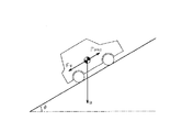
図5は、登坂路で停車中の車両に作用する力の関係を示している。ここで登坂路の勾配(傾斜角)を「θ」とし、車両に作用する重力を「g」とすると、車両は重力gの作用により、「g・sinθ」の力Fgで後方に引かれることになる。この力Fgは、車両に作用する重力gの車両後方向の成分(路面方向成分)であり、路面勾配θに応じて変化する。 FIG. 5 shows the relationship between the forces acting on the vehicle stopped on the uphill road. Here, when the slope (inclination angle) of the uphill road is “θ” and the gravity acting on the vehicle is “g”, the vehicle is pulled backward by the force Fg of “g · sin θ” by the action of the gravity g. become. This force Fg is a vehicle rear direction component (road surface direction component) of gravity g acting on the vehicle, and changes according to the road surface gradient θ.
また、図5に示すように、車両には、力Fgに抗する力としてマスタシリンダ圧PMCに応じた制動力Fpmcが働く。車両が坂路で停止した状態において、力Fgと制動力Fpmcとを比較し、Fpmc<Fgであると、ずり下がりが発生する可能性がある。 Further, as shown in FIG. 5, a braking force Fpmc corresponding to the master cylinder pressure PMC acts on the vehicle as a force against the force Fg. When the vehicle is stopped on a slope, the force Fg and the braking force Fpmc are compared, and if Fpmc <Fg, there is a possibility that the vehicle will slip down.
本例では、力Fgを車体重量Mで除算して得られる車両後方への加速度を勾配加速度Agと定義し、制動力Fpmcを車体重量Mで除算して得られる加速度を制動加速度Apmcと定義する。そして、Apmc<Agが成立すると、ずり下がりが発生する可能性があると判定するようにしている。 In this example, the vehicle rearward acceleration obtained by dividing the force Fg by the vehicle body weight M is defined as a gradient acceleration Ag, and the acceleration obtained by dividing the braking force Fpmc by the vehicle body weight M is defined as a braking acceleration Apmc. . Then, when Apmc <Ag is established, it is determined that there is a possibility that the sliding may occur.
ここで、ずり下がり防止制御を行う場合、ずり下がりの有無の判定に用いる勾配加速度Agを、停車前の走行中に取得しておく必要がある。本実施形態では、加速度センサSE7からの検出信号に基づき算出される車体加速度Gから、車輪速度センサSE3〜SE6の検出信号に基づき算出される車体速度VSを時間微分して得られる車体速度微分値DVSを差し引くことにより、勾配加速度Agを演算するようにしている。加速度センサSE7の検出信号に基づき算出した車体加速度Gには、車両に作用する重力加速度の車両前後方向成分である勾配加速度Agが含まれているのに対して、車両の車体速度VSを時間微分して得られる車体速度微分値DVSには勾配加速度Agが含まれていない。このため、車体加速度Gから車体速度微分値DVSを差し引くことにより、勾配加速度Agが取得される。 Here, when the slip prevention control is performed, it is necessary to acquire the gradient acceleration Ag used for the determination of the presence or absence of the slip during the traveling before the vehicle stops. In the present embodiment, the vehicle body speed differential value obtained by time-differentiating the vehicle body speed VS calculated based on the detection signals of the wheel speed sensors SE3 to SE6 from the vehicle body acceleration G calculated based on the detection signal from the acceleration sensor SE7. The gradient acceleration Ag is calculated by subtracting DVS. The vehicle body acceleration G calculated based on the detection signal of the acceleration sensor SE7 includes a gradient acceleration Ag that is a vehicle longitudinal component of gravity acceleration acting on the vehicle, whereas the vehicle body speed VS is time-differentiated. The vehicle body speed differential value DVS obtained in this way does not include the gradient acceleration Ag. Therefore, by subtracting the vehicle body speed differential value DVS from the vehicle body acceleration G, the gradient acceleration Ag is acquired.
また、ずり下がり防止制御では、ずり下がりの有無の判定に用いる制動加速度Apmcを、停車前の走行中に取得しておく必要がある。加速度センサSE7からの検出信号に基づき演算される車体加速度Gは、マスタシリンダ圧PMCの変動、すなわち車輪FR,FL,RR,RLに対する制動力の変動に伴い変動する。そこで、本実施形態では、マスタシリンダ圧(すなわち制動力)と車体加速度Gとに対応関係があることに着目し、車体加速度Gに基づきマスタシリンダ圧PMCに対応する値として制動加速度Apmcが取得される。この制動加速度Apmcは、マスタシリンダ圧PMCに応じた制動力Fpmcが車輪FR,FL,RR,RLに付与されるとき、その制動力Fpmcを車体重量Mで除算して得られる加速度に相当する。詳しくは、車体加速度Gから、クリープトルクに相当する加速度成分であるクリープ加速度Acと、ドラッグ分(走行抵抗等)に相当する加速度成分である加速度Adと勾配加速度Agとを除くことにより、制動加速度Apmcが算出される(Apmc=G−Ac+Ad+Ag)。そして、勾配加速度Agと制動加速度Apmcとを比較し、Apmc<Agである場合、ずり下がりが発生する可能性があると判定される。本実施形態では、Apmc<Agが成立して停車後に車両のずり下がりが発生する可能性があると予測された場合、車両のずり下がりを防止するため、停車までにエンジン12を事前に再始動させる。このエンジン12の再始動により、車両にクリープトルクを与えて車両のずり下がりを防止する。
In the slip prevention control, it is necessary to acquire the braking acceleration Apmc used for determining whether or not there is a slip while traveling before stopping. The vehicle body acceleration G calculated based on the detection signal from the acceleration sensor SE7 varies with the variation of the master cylinder pressure PMC, that is, the variation of the braking force with respect to the wheels FR, FL, RR, and RL. Therefore, in this embodiment, paying attention to the fact that there is a correspondence relationship between the master cylinder pressure (that is, braking force) and the vehicle body acceleration G, the braking acceleration Apmc is acquired as a value corresponding to the master cylinder pressure PMC based on the vehicle body acceleration G. The The braking acceleration Apmc corresponds to an acceleration obtained by dividing the braking force Fpmc by the vehicle body weight M when the braking force Fpmc corresponding to the master cylinder pressure PMC is applied to the wheels FR, FL, RR, and RL. Specifically, the braking acceleration is obtained by removing the creep acceleration Ac, which is an acceleration component corresponding to the creep torque, and the acceleration Ad and the gradient acceleration Ag, which are acceleration components corresponding to a drag component (travel resistance, etc.), from the vehicle body acceleration G. Apmc is calculated (Apmc = G-Ac + Ad + Ag). Then, the gradient acceleration Ag and the braking acceleration Apmc are compared, and if Apmc <Ag, it is determined that there is a possibility that the sliding may occur. In this embodiment, when it is predicted that Apmc <Ag is established and the vehicle may possibly fall after the vehicle stops, the
ところで、エンジン12の停止から再始動までのアイドルストップ時間が短くアイドルストップにより節減される燃料節減量Fdが、その後のエンジン12の再始動で消費される燃料消費量Fstより少ない場合、アイドルストップすると却って燃料消費量が増加して燃費を悪化させることになる。このため、本実施形態では、エンジン停止制御の実行条件が成立した場合、さらにエンジン12の自動停止によるアイドルストップにより節減できる燃料節減量Fdと、エンジン12の再始動時の燃料消費量Fstとを比較し、燃料節減量Fdが燃料消費量Fst以上である場合に、エンジン12を停止させてアイドルストップを実施するようにしている。
By the way, when the idle stop time from the stop to restart of the
具体的には、燃料節減量Fdと燃料消費量Fstとを比較するのではなく、エンジン12の停止から再始動までの予測されるアイドルストップ時間をエンジン停止可能予想時間Tesとして演算し、このエンジン停止可能予想時間Tesと、エンジン12の再始動時の燃料消費量Fcをアイドル時間に換算した設定時間T1とを比較する。エンジン12のアイドル時における単位時間当たりの燃料消費量Fidは、車種によっておおよそ一義的に決まっている。但し、車両に装備されたエアコンディショナーの駆動時と非駆動時でエンジン12のアイドル回転速度は変化する。そのため、アイドル回転速度のその変化範囲のうち上限値のアイドル回転速度(つまりエアコンディショナー駆動時のアイドル回転速度)のときの単位時間当たりの燃料消費量Fidを採用して、設定時間T1を設定している。もちろん、エアコンディショナーが駆動か非駆動かを判別し、その判別結果に応じて設定時間T1を切り換える構成を採用できる。
Specifically, instead of comparing the fuel saving amount Fd and the fuel consumption amount Fst, the estimated idle stop time from the stop of the
また、エンジン再始動時の燃料消費量Fstも、車種によっておおよそ一義的に決まっている。もちろん、エンジン運転モードに応じてエンジン再始動時の燃料消費量Fstが変化する場合は、その運転モードに応じた燃料消費量Fstを採用してもよい。本実施形態では、エンジン再始動時の燃料消費量Fstをアイドル時間に換算した値を、燃費向上効果のある時間T1(以下、「設定時間T1」ともいう。)として求める。この設定時間T1は、次式で与えられる。
T1=Fst/Fid … (1)
また、エンジン停止可能予想時間Tesは、エンジン12の停止時点からエンジン12の再始動時点までエンジン12を停止状態に保持できる予想時間(予測時間)であり、次式により与えられる。
Tes=VS/(DVS+Aet)…(2)
ここで、VSは車体速度、DVSは車体速度微分値、Aetはエンジントルク加速度である。但し、本例では、車体速度微分値DVSは、計算上、車両の減速過程(つまり車両後方向への加速度が増加する過程)で正の値をとる。また、エンジントルク加速度Aetは、エンジン運転状態で正の値をとる。なお、エンジントルク加速度Aetについては後述する。
Further, the fuel consumption amount Fst at the time of restarting the engine is roughly determined uniquely by the vehicle type. Of course, when the fuel consumption amount Fst at the time of engine restart changes according to the engine operation mode, the fuel consumption amount Fst according to the operation mode may be adopted. In the present embodiment, a value obtained by converting the fuel consumption amount Fst at the time of engine restart into an idle time is obtained as a time T1 (hereinafter, also referred to as “set time T1”) that has an effect of improving fuel efficiency. This set time T1 is given by the following equation.
T1 = Fst / Fid (1)
Further, the expected engine stop possible time Tes is an expected time (predicted time) during which the
Tes = VS / (DVS + Aet) (2)
Here, VS is a vehicle body speed, DVS is a vehicle body speed differential value, and Aet is an engine torque acceleration. However, in this example, the vehicle body speed differential value DVS takes a positive value in the deceleration process of the vehicle (that is, the process in which the acceleration in the vehicle rearward direction increases). Further, the engine torque acceleration Aet takes a positive value in the engine operating state. The engine torque acceleration Aet will be described later.
そして、エンジン停止可能予想時間Tesが、設定時間T1以上の場合(Tes≧T1が成立したとき)に、エンジン12を停止させるようにしている。そして、エンジン停止可能予想時間Tesが設定時間T1未満の場合は、エンジン12の自動停止(アイドルストップ)が却って燃費を悪化させるので、エンジン12の自動停止そのものを行わない。
The
但し、ずり下がり判定条件(Apmc<Ag)が不成立の場合、すなわち、制動加速度Apmcが勾配加速度Ag以上であって、車両のずり下がりを抑制しうるだけの制動力が確保される制動力条件(Apmc≧Ag)が成立した場合は、ずり下がり防止のためのエンジン12の再始動は行われない。このため、本実施形態では、停車時に車両のずり下がりを抑制しうるだけの制動力が確保されるか否かを、Apmc≧Agが成立するか否かにより判定する。そして、エンジン停止可能予想時間Tesの条件(Tes≧T1)が不成立でも、制動力条件(Apmc≧Ag)が成立した場合には、エンジン12の停止が許可されるようにしている。
However, when the slippage determination condition (Apmc <Ag) is not satisfied, that is, the braking force condition (where the braking acceleration Apmc is equal to or greater than the gradient acceleration Ag) and the braking force that can suppress the vehicle sliding down is secured ( When (Apmc ≧ Ag) is established, the
本実施形態では、エンジン停止制御の実行条件として、エンジン停止可能予想時間Tesの条件(Tes≧T1)と、制動力条件(Apmc≧Ag)を除く、その他のアイドルストップ条件(以下、「IS条件」ともいう。)が設定されている。その他のIS条件とは、具体的には、ブレーキスイッチSW1がオンしていること(ブレーキスイッチオン)、マスタシリンダ圧PMCが規定圧P1を超えていること(PMC>P1)、車体速度VSが規定速度V1(例えば20km/h)以下となっていること(VS≦V1)の各条件がアンド条件で成立することである。もちろん、その他のIS条件は、ブレーキスイッチオン条件とマスタシリンダ圧条件のうち一方を無くすなど、適宜な条件に変更してもよい。 In the present embodiment, as an execution condition for engine stop control, other idle stop conditions (hereinafter referred to as “IS conditions”) except for the condition of the expected engine stop time Tes (Tes ≧ T1) and the braking force condition (Apmc ≧ Ag). Is also set.). Specifically, the other IS conditions are that the brake switch SW1 is on (brake switch on), the master cylinder pressure PMC exceeds the specified pressure P1 (PMC> P1), and the vehicle body speed VS is Each condition that a specified speed V1 (for example, 20 km / h) or less (VS ≦ V1) is satisfied under the AND condition. Of course, other IS conditions may be changed to appropriate conditions such as eliminating one of the brake switch-on condition and the master cylinder pressure condition.
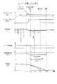
図6〜図8は、こうした本実施形態の制御態様のタイミングチャートを示している。各図には、登坂路での車両の停車前におけるブレーキスイッチSW1の信号、マスタシリンダ圧PMC、加速度センサSE7から出力される車体加速度G、エンジン回転速度、車体速度VS及び車体速度微分値DVSの推移を示している。なお、本実施形態では、車体速度VSには車輪速度を用いる。そして、車体速度VSは、車輪速度の時間微分値である車輪加速度を単位時間毎に積算した積算値を、前回の車輪速度に加算することにより求められる。また、図6〜図8では、車体加速度Gと車体速度微分値DVSについては、加速度センサSE7により検出される車体加速度G及び計算上の車体速度微分値DVSと正負が異なるが、それぞれ車両後方向が負の値をとるように示している。 6 to 8 show timing charts of the control mode of this embodiment. Each figure shows the signal of the brake switch SW1, the master cylinder pressure PMC, the vehicle body acceleration G output from the acceleration sensor SE7, the engine rotation speed, the vehicle body speed VS, and the vehicle body speed differential value DVS before the vehicle stops on the uphill road. It shows the transition. In the present embodiment, the wheel speed is used as the vehicle body speed VS. The vehicle body speed VS is obtained by adding an integrated value obtained by integrating the wheel acceleration, which is a time differential value of the wheel speed, per unit time to the previous wheel speed. 6-8, the vehicle body acceleration G and the vehicle body speed differential value DVS are different from the vehicle body acceleration G detected by the acceleration sensor SE7 and the calculated vehicle body speed differential value DVS in positive and negative directions, respectively. Is shown to take a negative value.
図6を用いて、アイドルストップ処理について説明する。なお、図6は、エンジン停止可能予想時間Tesが設定時間T1以上となる条件を満たしたためにエンジン12を停止させる場合のタイミングチャートである。図6において、時刻t0では、車両はエンジン12が運転された状態で走行している。
The idle stop process will be described with reference to FIG. FIG. 6 is a timing chart when the
ここで、図6に示すように、車両走行中における車体加速度Gには、勾配分の加速度Ag、エンジントルク分の加速度Aet(クリープトルク加速度に相当)、ドラッグ分の加速度Adの各加速度成分が含まれる。車両前方に作用する加速度を「正」、車両後方に作用する加速度を「負」とすると、勾配加速度Agが負、エンジントルク加速度Aetが正、ドラッグ分の加速度Adが負の値としてそれぞれ車両に加わった結果として、加速度センサSE7により車体加速度Gは検出される。但し、本実施形態の加速度センサSE7は、図6における実際の加速度の正負と異なり、計算の便宜上、車両後方向の加速度を正の値として出力する。なお、ドラッグ分の加速度Adとは、車輪と路面との間の走行抵抗などによる負の加速度を指す。 Here, as shown in FIG. 6, the vehicle body acceleration G during traveling of the vehicle includes acceleration components Ag for gradient, acceleration Aet for engine torque (corresponding to creep torque acceleration), and acceleration Ad for drag. included. Assuming that the acceleration acting on the front side of the vehicle is “positive” and the acceleration acting on the rear side of the vehicle is “negative”, the gradient acceleration Ag is negative, the engine torque acceleration Aet is positive, and the acceleration Ad for dragging is negative. As a result of the addition, the vehicle body acceleration G is detected by the acceleration sensor SE7. However, the acceleration sensor SE7 of the present embodiment outputs the acceleration in the rearward direction of the vehicle as a positive value for convenience of calculation, unlike the actual positive / negative acceleration in FIG. Note that the acceleration Ad for the drag indicates a negative acceleration due to a running resistance between the wheel and the road surface.
この車両走行中において、時刻t1で、運転手がブレーキペダル15を操作すると(踏み込むと)、ブレーキスイッチSW1がオンするとともに、このブレーキ操作によりマスタシリンダ圧PMCが上昇し、車輪に制動力が付与される。この結果、時刻t1から車体速度VSが低下し始める。このとき、マスタシリンダ圧PMC分の制動加速度Apmcが、車両に対して進行方向と反対方向(後方向)に負の加速度として加わるので、車体加速度Gは、その時々のマスタシリンダ圧PMC分の加速度Apmcだけ小さくなり、負の値をとる。また、ブレーキ操作によりマスタシリンダ圧PMCは規定圧P1に到達する。 While the vehicle is running, when the driver operates the brake pedal 15 (depresses) at time t1, the brake switch SW1 is turned on, and the master cylinder pressure PMC is increased by this brake operation, and braking force is applied to the wheels. Is done. As a result, the vehicle body speed VS starts to decrease from time t1. At this time, the braking acceleration Apmc corresponding to the master cylinder pressure PMC is applied as a negative acceleration in the direction opposite to the traveling direction (rearward direction) with respect to the vehicle, so that the vehicle body acceleration G is the acceleration corresponding to the master cylinder pressure PMC at that time. It becomes smaller by Apmc and takes a negative value. Further, the master cylinder pressure PMC reaches the specified pressure P1 by the brake operation.
車体速度VSは、制動加速度Apmcが加わって小さくなった車体加速度G(図6ではG<0)に等しい変化率で減速する。やがて車体速度VSは、規定速度V1以下になる。
そして、車両の走行減速中の時刻t2の時点で、その他のIS条件が成立すると、続いてエンジン停止可能予想時間Tesが演算される。エンジン停止可能予想時間Tesは、エンジン12を停止させた場合に、停車後に車両のずり下がりを防止するためにエンジン12の再始動を行うと仮定し、エンジン12の停止時点(現時点)から再始動が開始されるまでの間の時間、すなわちエンジン12を停止状態に保持可能な時間の予想時間として算出される。
The vehicle body speed VS is decelerated at a rate of change equal to the vehicle body acceleration G (G <0 in FIG. 6) which is reduced by the addition of the braking acceleration Apmc. Eventually, the vehicle body speed VS becomes equal to or less than the specified speed V1.
Then, when other IS conditions are satisfied at the time t2 when the vehicle is traveling and decelerating, an expected engine stop possible time Tes is subsequently calculated. The expected engine stop time Tes assumes that the
時刻t2において車輪速度センサSE3〜SE6の少なくとも一つの検出信号から得られる車体速度VSは、エンジン停止前なので、エンジントルク分の加速度Aetが加わった車体加速度Gで減速する場合の車体速度に相当する。図6における二点鎖線は、エンジントルク分の加速度Aetが加わった車体加速度Gで減速する場合の速度プロファイルを示す。本実施形態では、エンジン停止可能予想時間Tesは、エンジン停止状態における減速過程を想定して算出する。このため、図6の二点鎖線の速度プロファイルに対して、エンジン停止状態で消滅するエンジントルク分の加速度Aetを除いた車体加速度(=DVS+Aet)で減速する場合を想定して、エンジン停止可能予想時間Tesを演算する。 Since the vehicle speed VS obtained from at least one detection signal of the wheel speed sensors SE3 to SE6 at time t2 is before the engine is stopped, it corresponds to the vehicle speed when the vehicle is decelerated at the vehicle acceleration G with the acceleration Aet corresponding to the engine torque. . A two-dot chain line in FIG. 6 indicates a speed profile when the vehicle is decelerated at the vehicle body acceleration G to which the acceleration Aet for the engine torque is added. In the present embodiment, the expected engine stop possible time Tes is calculated assuming a deceleration process in the engine stop state. Therefore, with respect to the speed profile indicated by the two-dot chain line in FIG. 6, it is possible to stop the engine assuming that the vehicle is decelerated at the vehicle body acceleration (= DVS + Aet) excluding the acceleration Aet corresponding to the engine torque that disappears in the engine stop state Time Tes is calculated.
このため、車体速度VSの時間微分である車体速度微分値DVSから、消滅するエンジントルク分の加速度Aetを除き、エンジン停止可能予想時間Tesを、前記(2)式で示した計算式 Tes=VS/(DVS+Aet)により算出する。但し、この計算式上において、車両減速過程でDVS>0であり、またAet>0である。 For this reason, the acceleration Aet corresponding to the disappearing engine torque is excluded from the vehicle body speed differential value DVS, which is the time derivative of the vehicle body speed VS, and the expected engine stop possible time Tes is calculated by the equation shown in the equation (2) Tes = VS / (DVS + Aet). However, in this calculation formula, DVS> 0 and Aet> 0 in the vehicle deceleration process.
そして、このエンジン停止可能予想時間Tesと設定時間T1とを比較し、Tes>T1が成立すれば、燃費向上効果が得られるので、時刻t2からエンジン12が停止される。この結果、時刻t2からエンジン回転速度は低下し、やがてゼロになる。そして、エンジン回転速度がゼロになると、エンジントルク分が消滅するため、実際の車体速度VSは、予想の車体速度と同じように図6における実線に沿って低下する。なお、時刻t2〜t3の期間においては、徐々に低下するエンジントルク分に応じた可変の加速度Aetを用いて、エンジン停止可能予想時間Tesを演算してもよい。
Then, the expected engine stop possible time Tes and the set time T1 are compared, and if Tes> T1 is satisfied, the fuel efficiency improvement effect is obtained, so the
また、図7のタイミングチャートに示すように、ブレーキペダル15の操作量が大きいため、制動加速度Apmcが勾配加速度Agより大きく、停車後に車両のずり下がりを防止できるだけの制動力が確保される場合は、仮にエンジン停止可能予想時間Tesが設定時間T1より短くても(Tes<T1)、エンジン12を停止させる。これは、停車後にずり下がりの防止を目的とするエンジン12の再始動が不要だからである。このように停車時にエンジン再始動が不要な場合も、エンジン12が停止されるようになっている。
Further, as shown in the timing chart of FIG. 7, when the operation amount of the
本実施形態では、エンジン再始動開始時期は、ずり下がり距離Lが許容距離La以下に抑えられるように決められる。停車後のずり下がり距離Lが許容距離Laに至るまでに要する予測時間T2は、現時点から停車までに要する時間Taと、停車後に車両のずり下がり距離Lが許容距離Laに至るまでに要する時間Tbとの和として求められる(T2=Ta+Tb)。時間Taは、車体速度VSを車体速度微分値DVSで除算して求められる(Ta=VS/DVS)。また、時間Tbは、路面勾配θと時間Tbとの対応関係を示した図示しないマップを用いて求められる。なお、本実施形態では、一例として許容距離Laをゼロとしている(La=0)。このため、予測時間T2は、T2=VS/DVSにより演算される。 In this embodiment, the engine restart start timing is determined so that the sliding distance L can be suppressed to the allowable distance La or less. The estimated time T2 required for the sliding distance L after the stop to reach the allowable distance La is the time Ta required from the current time to the stop and the time Tb required for the vehicle falling distance L to reach the allowable distance La after the stop. (T2 = Ta + Tb). The time Ta is obtained by dividing the vehicle body speed VS by the vehicle body speed differential value DVS (Ta = VS / DVS). Further, the time Tb is obtained by using a map (not shown) showing the correspondence between the road surface gradient θ and the time Tb. In the present embodiment, the allowable distance La is set to zero (La = 0) as an example. For this reason, the prediction time T2 is calculated by T2 = VS / DVS.
そして、エンジン停止後における車両の減速過程において逐次計算される予測時間T2が、エンジン12の再始動の開始からその終了までに必要な時間Teng(以下「再始動必要時間Teng」という。)に達した時点で、エンジン12の再始動の開始が許可されるようになっている。詳細には、車両の停止までの予測時間T2は、車体速度VSが減少していくに従い、減少していく。そして、予め車両毎に定められた再始動必要時間Tengまで小さくなると、エンジン12の再始動が開始される。このため、本実施形態では、ずり下がり距離Lが許容距離Laに達するまでにエンジン12の再始動が完了する。このように本実施形態では、車体速度VSが許容範囲内でできるだけ小さくなるまでエンジン再始動開始タイミングを待つことにより、燃費向上効果を維持しつつ、車両のずり下がりを適切に防止することが可能である。
Then, the predicted time T2 calculated sequentially in the deceleration process of the vehicle after the engine stops reaches the time Teng required from the start to the end of the restart of the engine 12 (hereinafter referred to as “restart required time Teng”). At this point, the start of restart of the
なお、本実施形態では、エンジン停止可能予想時間Tesを、前記(2)式を用いて計算するが、再始動必要時間Tengを考慮した次式を採用することもできる。
Tes=VS/(DVS−Aet)−Teng …(3)
さて、ブレーキ用ECU55は、予め設定された所定周期(例えば0.01秒周期)毎にアイドルストップ制御ルーチンを実行する。このアイドルストップ制御ルーチンは、燃費向上および環境上の効果などを期待し、エンジン12を自動的に停止させるための図3に示すエンジン停止制御ルーチンと、エンジン12を再始動させるための図4に示すエンジン再始動制御ルーチンとを含む。アイドルストップ制御ルーチンにおけるエンジン再始動制御では、ブレーキペダル15の操作量を規定量以下に戻してマスタシリンダ圧PMCが規定圧Px以下になったとき、アクセル開度AP>0になったときなどの予め決められた再始動条件の成立時にエンジン12を再始動させる。本実施形態におけるエンジン再始動制御では、さらに停車後に車両のずり下がりを防止するずり下がり防止制御が含まれる。図4に示すエンジン再始動制御ルーチンは、エンジン停止制御のうち、ずり下がり防止制御のためにエンジン12を再始動させる制御部分を示す。
In the present embodiment, the expected engine stop possible time Tes is calculated using the above equation (2), but the following equation that takes the restart required time Teng into consideration can also be adopted.
Tes = VS / (DVS-Aet) -Teng (3)
Now, the
まず、図3を用いてエンジン停止制御について説明する。さて、エンジン運転状態での車両の走行中において、ブレーキ用ECU55は、図3に示すエンジン停止制御ルーチンを実行する。このエンジン停止制御ルーチンは、所定の停止条件が成立した場合に、エンジン12の自動的な停止を許可する停止制御のための処理である。
First, engine stop control will be described with reference to FIG. Now, during traveling of the vehicle in the engine operating state, the
ブレーキ用ECU55は、まずステップS11において、その他のアイドルストップ条件(IS条件)が成立するか否かを判断する。その他のIS条件が成立すると、ステップS12に進み、その他のIS条件が不成立であれば、当該ルーチンを終了する。なお、本実施形態では、その他のIS条件が、停止制御の実行条件に相当し、その他のIS条件が成立するか否かを判定するブレーキ用ECU55が、第1の判定手段としても機能する。また、ステップS11が、第1の判定ステップに相当する。
First, in step S11, the
ステップS12では、エンジン停止可能予想時間Tesを演算する。このエンジン停止可能予想時間Tesは、前記(2)式に示す計算式 Tes=車体速度VS/(DVS+Aet)により算出される。 In step S12, the expected engine stop possible time Tes is calculated. The expected engine stop possible time Tes is calculated by the calculation formula Tes = vehicle speed VS / (DVS + Aet) shown in the equation (2).
次のステップS13では、エンジン停止可能予想時間Tesが、燃費向上効果のある設定時間T1以上(つまりTes≧T1)であるか否かを判定する。Tes≧T1が成立すればステップS15に進み、Tes≧T1が不成立であればステップS14に進む。なお、本実施形態では、エンジン停止可能予想時間Tesを求めて、Tes≧T1が成立するか否かを判定するブレーキ用ECU55が、第3の判定手段としても機能する。また、ステップS12,S13が、第3の判定ステップに相当する。
In the next step S13, it is determined whether or not the expected engine stop possible time Tes is equal to or longer than a set time T1 having an effect of improving fuel efficiency (that is, Tes ≧ T1). If Tes ≧ T1 is established, the process proceeds to step S15. If Tes ≧ T1 is not established, the process proceeds to step S14. In the present embodiment, the
ステップS15では、エンジン12の停止を許可する。すなわち、ブレーキ用ECU55は、エンジン用ECU17に停止指令を送信する。この結果、エンジン用ECU17はエンジン12を停止させる。なお、本実施形態では、エンジン12の停止を許可するブレーキ用ECU55が、停止制御手段としても機能する。また、ステップS15が、停止制御ステップに相当する。
In step S15, the stop of the
一方、Tes≧T1が不成立の場合は、ステップS14において、制動加速度Apmcが勾配加速度Ag以上(Apmc≧Ag(閾値))であるか否かを判定する。Apmc≧Agが成立すれば、エンジン12を再始動しなくてもずり下がりが発生しないだけの制動力が確保されることを意味する。このため、Apmc≧Agが成立すれば、ステップS15に進んで、エンジン12の停止を許可する。すなわち、ブレーキ用ECU55は、エンジン用ECU17に停止指令を送信する。この結果、エンジン用ECU17はエンジン12を停止させる。なお、本実施形態では、Apmc≧Agが成立するか否かを判定するブレーキ用ECU55が、第4の判定手段としても機能する。また、ステップS14が、第4の判定ステップに相当する。
On the other hand, if Tes ≧ T1 is not established, it is determined in step S14 whether the braking acceleration Apmc is equal to or higher than the gradient acceleration Ag (Apmc ≧ Ag (threshold)). If Apmc ≧ Ag is established, it means that a braking force sufficient to prevent the sliding down without securing the
一方、ステップS14において、Apmc≧Agが不成立と判定された場合は、当該ルーチンを終了する。この場合、エンジン12の停止は許可されない。すなわち、アイドルストップによる燃費向上効果が得られないので、エンジン12の停止は許可されない。
On the other hand, if it is determined in step S14 that Apmc ≧ Ag is not established, the routine ends. In this case, the stop of the
次に、エンジン12を停止する場合(Tes≧T1)の処理を、図6に示すタイミングチャートに従って説明する。車両がエンジン運転状態で走行しているとき、時刻t1において、運転手がブレーキペダル15を操作すると、ブレーキスイッチSW1がオンするとともに、マスタシリンダ圧PMCが上昇して規定圧P1に達する。そして、車輪FR,FL,RR,RLにマスタシリンダ圧PMCに応じた制動力が付与されて、車両は減速し、車体速度VSが規定速度V1以下になる。この結果、時刻t2になると、その他のIS条件が成立する。すなわち、ブレーキスイッチオン、マスタシリンダ圧PMC>規定圧P1、車体速度VS≦規定速度V1の各条件がアンド条件で成立する。
Next, processing when the
その他のIS条件が成立すると、次にエンジン停止可能予想時間Tesを求め、Tes≧T1が成立するか否かを判定する。そして、Tes≧T1が成立すれば、時刻t2からエンジン12が停止される。この結果、時刻t3までにエンジントルク分が消滅し、車体速度VSは、図6における実線に沿って低下する。そして、時刻t4で、車両は停止する。
If the other IS conditions are satisfied, next, an expected engine stop possible time Tes is obtained, and it is determined whether or not Tes ≧ T1 is satisfied. And if Tes> = T1 is materialized, the
このエンジン停止後の車両の走行中において、ブレーキ用ECU55は、図4に示すエンジン再始動制御ルーチンを実行する。このエンジン再始動制御ルーチンは、所定の再始動条件が成立した場合に、停車後の車両のずり下がりを許容範囲内に抑制することを目的として、エンジン12の自動的な再始動を許可するための処理である。
During traveling of the vehicle after the engine is stopped, the
図4に示すエンジン再始動制御ルーチンは、エンジン12が停止した状態での登坂走行中に、ブレーキ用ECU55により、一定の制御周期(例えば0.01秒)毎に繰り返し実行される。
The engine restart control routine shown in FIG. 4 is repeatedly executed by the
さて、本ルーチンが開始されると、まずステップS21において、制動加速度Apmcと勾配加速度Agとの比較により、停車後に車両のずり下がりが発生する(Apmc<Agが成立する)か否かを判定する。ここで制動加速度Apmcが勾配加速度Ag以上(Apmc≧Ag)であり、停車後のずり下がりが発生しないと判定されたときには(S21で否定判定)、そのまま今回の本ルーチンの処理が終了される。なお、本実施形態では、Apmc<Agが成立するか否かを判定するブレーキ用ECU55が、第2の判定手段としても機能する。また、ステップS21が、第2の判定ステップに相当する。
When this routine is started, first, in step S21, it is determined whether or not the vehicle slips after stopping (Apmc <Ag is established) by comparing the braking acceleration Apmc and the gradient acceleration Ag. . Here, when the braking acceleration Apmc is equal to or greater than the gradient acceleration Ag (Apmc ≧ Ag) and it is determined that no slippage occurs after the vehicle stops (No determination in S21), the processing of this routine is terminated as it is. In the present embodiment, the
一方、制動加速度Apmcが勾配加速度Ag未満(Apmc<Ag)であり、停車後に車両のずり下がりが発生すると判定されたときには(S21で肯定判定)、続くステップS22において、車両停車までの予測時間T2(=VS/DVS)が演算される。そして続くステップS23で、演算された予測時間T2が再始動必要時間Teng以下であるか否かが判定される。 On the other hand, when the braking acceleration Apmc is less than the gradient acceleration Ag (Apmc <Ag), and it is determined that the vehicle will drop after the vehicle stops (affirmative determination in S21), in the following step S22, the predicted time T2 until the vehicle stops (= VS / DVS) is calculated. In the subsequent step S23, it is determined whether or not the calculated predicted time T2 is equal to or shorter than the restart required time Teng.
ここで、予測時間T2が再始動必要時間Tengを超えていれば(S23で否定判定)、未だエンジン12の再始動を開始する必要はないとして、そのまま今回の処理が終了される。一方、予測時間T2が再始動必要時間Teng以下であれば(S23で肯定判定)、ステップS24においてエンジン12の再始動を許可する。すなわち、ブレーキ用ECU55は、エンジン用ECU17に再始動指令を送信する。
Here, if the predicted time T2 exceeds the restart required time Teng (negative determination in S23), it is not necessary to start restarting the
そして、エンジン用ECU17は、再始動指令を受信した場合に、エンジン12を再始動させると共に、再始動処理が完了した旨の信号をブレーキ用ECU55に送信する。エンジン用ECU17から信号を受信したブレーキ用ECU55は、エンジン12の再始動が完了したと判断する。
When the restart command is received, the
図6では、マスタシリンダ圧PMCが規定圧P1程度と比較的小さく、Apmc<Agが成立し、停車後に車両のずり下がりが発生すると判定される。このため、停車の時刻t4よりも再始動必要時間Tengだけ前の時刻に、エンジン12の再始動が開始され、停車までに再始動が完了する。この結果、停車時に車両のずり下がりが発生しない。この再始動必要時間Tengは、車両のずり下がり距離Lが予め定められた許容距離Laを超えないように所定の方法で決定される。
In FIG. 6, it is determined that the master cylinder pressure PMC is relatively small as about the specified pressure P1, Apmc <Ag is established, and the vehicle is lowered after the vehicle stops. For this reason, the restart of the
また、図7は、エンジン停止可能予想時間Tesが設定時間T1より小さい(Tes<T1)ものの、勾配加速度Agより制動加速度Apmcの方が大きく、ずり下がりを抑制しうる制動力が確保される場合におけるタイミングチャートを示す。 Further, FIG. 7 shows the case where the expected engine stop possible time Tes is smaller than the set time T1 (Tes <T1), but the braking acceleration Apmc is larger than the gradient acceleration Ag, and a braking force capable of suppressing the sliding is secured. The timing chart in is shown.
エンジン運転状態での車両の走行中に、時刻t11でブレーキペダル15が比較的強く操作され、ブレーキスイッチSW1がオンするとともに、マスタシリンダ圧PMCが上昇して規定圧P1を超えて所定圧P2に達する。この結果、車両は減速し、時刻t12で、その他のIS条件が成立すると、次にエンジン停止可能予想時間Tes(=VS/(DVS+Aet)が演算され、Tes>T1が成立するか否かが判定される。図7の例では、エンジン停止可能予想時間Tesが設定時間T1より短く、Tes>T1が不成立となる。
While the vehicle is running in the engine operating state, the
しかし、制動加速度Apmcが勾配加速度Agよりも大きく、ずり下がりを防止できるだけの制動力が確保されるため、ずり下がり防止を目的とするエンジン12の再始動の必要がない。このため、Apmc>Agが成立した時刻t13で、エンジン12の停止が許可される。この結果、時刻t13からエンジン回転速度は低下しやがてゼロになる。そして、エンジン回転速度がゼロになると(時刻14)、エンジントルク分が消滅する。このため、実際の車体速度VSは、予想どおり図7の実線に沿って低下する。そして、時刻t15で停車したときには比較的強い制動力が確保されているので、エンジン12が再始動されなくても、車両のずれ下がりは発生しない。
However, since the braking acceleration Apmc is larger than the gradient acceleration Ag and a braking force sufficient to prevent the sliding is ensured, it is not necessary to restart the
さらに図8は、エンジンを停止しない場合のタイミングチャートを示す。エンジン運転状態での車両の走行中に、時刻t21でブレーキペダル15が操作されると、ブレーキスイッチSW1がオンするとともに、マスタシリンダ圧PMCが上昇して規定圧P1に達する。この結果、車両が減速し、車体速度VSが規定速度V1以下になった時刻t22で、その他のIS条件が成立すると、次にエンジン停止可能予想時間Tes(=VS/(DVS+Aet))を演算し、Tes>T1が成立するか否かを判定する。図8の例では、車体速度VSが、エンジントルク分の加速度Aetが消滅した二点鎖線で示す速度プロファイルに沿って低下して時刻t24で停車する場合を想定したエンジン停止可能予想時間Tesを用いて、Tes>T1が成立するか否かが判定される。図8の例では、Tes>T1が不成立なので、エンジン12を停止させても、燃費向上効果が得られない。
Further, FIG. 8 shows a timing chart when the engine is not stopped. When the
また、マスタシリンダ圧PMCが規定圧P1程度と比較的小さく、制動加速度Apmcが勾配加速度Agよりも小さいため、ずり下がりを抑制しうる制動力も確保されない。このため、停車後に車両のずり下がり防止するためにクリープトルクが必要である。よって、エンジン12が停止されることはない。エンジントルク分の加速度Aetが消滅しないため、実際の車体速度VSは、図8の実線に沿って低下する。そして、停車後に運転を継続しているエンジン12によりクリープトルクが与えられるので、車両のずれ下がりは発生しない。但し、登坂路の路面勾配θがかなり大きく、車両に作用する重力の勾配成分の力Fgが、クリープトルクとブレーキ操作による制動力との和を上回る場合は、停車後に車両がゆっくりずり下がることが起こりうる。この場合、ずり下がり速度がゆっくりなので、運転手は比較的余裕をもってブレーキペダル15を更に踏み込んで、車両のそれ以上のずり下がりを防止する。
Further, since the master cylinder pressure PMC is relatively small as about the specified pressure P1, and the braking acceleration Apmc is smaller than the gradient acceleration Ag, the braking force that can suppress the sliding is not ensured. For this reason, creep torque is required to prevent the vehicle from sliding down after stopping. Therefore, the
以上説明した本実施形態の車両の制御装置によれば、以下の効果を得ることができる。
(1)エンジン12の自動停止、自動再始動を行うブレーキ用ECU55は、その他のIS条件が成立すると、エンジン停止時点から停車後のずり下がりの防止を目的として行われるエンジン12を再始動するまでのエンジン停止期間(アイドルストップ時間)で節減できる燃料節減量Fdが、エンジン12の再始動に要する燃料消費量Fst以上であるか否かを判定する。そして、燃料節減量Fdが燃料消費量Fst以上であれば、ブレーキ用ECU55は、エンジン12の停止を許可する。このため、燃料節減量Fdより燃料消費量Fstの方が却って多くなるようなエンジン停止期間しか確保できない場合は、エンジン12の停止が許可されないので、従来に比べてさらなる燃費向上効果を得ることができる。
According to the vehicle control apparatus of the present embodiment described above, the following effects can be obtained.
(1) The
(2)ブレーキ用ECU55は、その他のIS条件が成立すると、エンジン停止時点から、停車後のずり下がりの防止を目的として行われるエンジン12の再始動までのエンジン停止期間の予想値であるエンジン停止可能予想時間Tesを算出し、このエンジン停止可能予想時間Tesが設定時間T1以上であるか否かを判定する。つまり、燃料節減量Fdと燃料消費量Fstとを直接比較するのではなく、これらの値Fd,Fstを、エンジン12のアイドル状態における単位時間当たりの燃料消費量Fidを用いてアイドル時間相当の時間にそれぞれ換算した、エンジン停止可能予想時間Tesと設定時間T1とを比較する。よって、燃料節減量Fd及び燃料消費量Fstを求めることなく、これらの時間換算値であるエンジン停止可能予想時間Tesと設定時間T1とを用いて、燃料節減量Fdが燃料消費量Fst以上であることを、間接的に判定することができる。よって、既存の車輪速度センサSE3〜SE6の検出結果から演算により取得できるエンジン停止可能予想時間Tesを用いて、比較的簡単な処理で判定を行うことができる。
(2) When the other IS conditions are satisfied, the
(3)燃料節減量が燃料消費量未満である場合、車両に作用する重力の勾配成分の力Fgに応じた勾配加速度Agと、ブレーキペダル15の操作量(踏み量)に応じたマスタシリンダ圧PMCから決まる制動加速度Apmcとを比較し、Apmc≧Agが成立すれば、停車後にずり下がりが発生しないと判定し、エンジン12の停止が許可される。つまり、停車時に車両に作用する重力の勾配成分の力Fgに抗することのできる制動力が得られる場合は、エンジン12の停止が許可される。よって、アイドルストップの実施頻度を増やして、さらなる燃費向上効果を得ることができる。
(3) When the fuel saving amount is less than the fuel consumption amount, the master cylinder pressure corresponding to the gradient acceleration Ag corresponding to the force Fg of the gradient component of gravity acting on the vehicle and the operation amount (stepping amount) of the
(4)エンジン停止可能予想時間Tesが設定時間T1未満であり、かつ停車後のずり下がりを防止できるだけの制動力が確保できない場合(Apmc≧Agが不成立)は、エンジン12の停止が許可されない。よって、エンジン12を停止させたばかりにそのアイドルストップ時間で節減できる燃料節減量Fdよりも、エンジン12を再始動させるための燃料消費量Fstの方が多くなって、アイドルストップの実施が却って燃費を悪化させ事態を極力回避できる。
(4) If the expected engine stop possible time Tes is less than the set time T1 and a braking force sufficient to prevent the vehicle from slipping down after stopping is not secured (Apmc ≧ Ag is not established), the
(5)ずり下がりが発生する可能性がある(Apmc<Ag)と判定されたときには、停車時までに完了するようにエンジン12の再始動を開始する。より具体的には、車両のずり下がりの発生が予測されるときには、停車までの予測時間T2が再始動必要時間Tengに達した時点でエンジン12の再始動を開始する。このため、停車後に車両のずり下がりが発生せず、登坂路での車両の停車後のずり下がりを好適に防止できる。
(5) When it is determined that there is a possibility of slippage (Apmc <Ag), the
(6)停車後にずり下がりが発生するか否かの判定を、ブレーキペダル15の操作量(踏み量)に応じたマスタシリンダ圧PMCから決まる制動加速度Apmcと、車体加速度Gと車体速度微分値DVSとの差分から決まる勾配加速度Agとを用いて行う。そして、勾配加速度Agが制動加速度Apmc上回るときに車両のずり下がりが発生すると判定する。そのため、車両のずり下がりの防止を目的とするエンジン12の再始動の要否を的確に判定することができる。
(6) The determination as to whether or not a slip occurs after the vehicle stops is made by determining whether the braking acceleration Apmc is determined from the master cylinder pressure PMC corresponding to the operation amount (stepping amount) of the
なお、上記実施形態は、以下のように変更して実施することもできる。
・前記実施形態では、燃料節減量Fdと燃料消費量Fcに応じた設定値F1とを、それぞれアイドル時間に換算したエンジン停止可能予想時間Tesと設定時間T1とを比較したが、燃料節減量Fdと設定値F1とを比較し、Fd≧F1が成立するか否かを判定する構成としてもよい。この場合、エンジン12の燃焼室内に燃料を噴射するインジェクタを有する燃料噴射装置がエンジンアイドル状態下で単位時間当たりに消費する燃料量に、エンジン12の停止から再始動までのエンジン停止時間を乗じることで、燃料節減量Fdは演算される。また、エンジン始動時に取得した実際の燃料消費量Fcに応じた設定値F1をブレーキ用ECU55のメモリに記憶しておく。そして、第3の判定手段として機能するブレーキ用ECU55は、上記演算により取得した燃料節減量Fdが設定値F1以上であるか否かを判定する構成とする。
In addition, the said embodiment can also be changed and implemented as follows.
In the above embodiment, the fuel saving amount Fd and the set value F1 corresponding to the fuel consumption amount Fc are respectively compared with the estimated engine stop possible time Tes converted into the idle time and the set time T1, but the fuel saving amount Fd And the set value F1 may be compared to determine whether or not Fd ≧ F1 is satisfied. In this case, the amount of fuel consumed per unit time by the fuel injection device having an injector for injecting fuel into the combustion chamber of the
・燃料節減量Fdが燃料消費量Fcと同じである場合(前記実施形態では、Tes=T1の場合)は、エンジン12の停止を許可する構成としたが、エンジンの停止を許可しない構成としてもよい。すなわち、少なくとも燃費を悪化させる場合にエンジン12の停止を許可しない構成であればよい。さらに、燃料消費量Fcに対して許容量α又は、エンジン停止可能予想時間Tesに対して許容量αに相当する許容時間Tαを設定し、第3の判定手段が、Fd≧Fc+Fα、又はTes≧T1+Tαの成立を判定する構成としてもよい。この構成によれば、計算上又は設定上の値と実際の値との間に誤差があっても、燃料節減効果があるときに限りエンジン12を停止させることができる。もちろん、第3の判定手段の判定条件を、Fd≧Fc−Fα、又はTes≧T1−Tαとしてもよい。要するに、設定値は、エンジン再始動時の燃料消費量に応じて設定される値であればよく、燃料消費量やその換算時間に所定の許容値を考慮した値でもよい。
When the fuel saving amount Fd is the same as the fuel consumption amount Fc (in the above embodiment, when Tes = T1), the
・前記実施形態では、ずり下がり判定の際に制動加速度Apmcと勾配加速度Ag(閾値)とを比較したが、制動力と車両に作用する重力の車両前後方向成分(路面方向成分)の力Fg(閾値)とを比較したり、マスタシリンダ圧PMCと力Fgのマスタシリンダ圧換算値(閾値)とを比較したりしてもよい。 In the above-described embodiment, the braking acceleration Apmc and the gradient acceleration Ag (threshold) are compared in the determination of the sliding down, but the force Fg (the vehicle front-rear direction component (road surface direction component)) of the braking force and the gravity acting on the vehicle. Threshold value) or a master cylinder pressure conversion value (threshold value) of the master cylinder pressure PMC and the force Fg may be compared.
・マスタシリンダ圧PMCを検出する圧力センサSE2を備える車両においては、圧力センサSE2により検出されるマスタシリンダ圧PMCを基に制動加速度Apmcを取得してもよい。ブレーキ用ECU55のメモリには、例えばマスタシリンダ圧PMCと制動加速度Apmc(又は制動力Fpmc)との対応関係を示す図示しないマップが記憶される。ブレーキ用ECU55は、マスタシリンダ圧PMCを基にマップを参照して制動加速度Apmc(又は制動力Fpmc)を取得し、制動加速度Apmcと勾配加速度Agとの比較(又は制動力Fpmcと力Fgとの比較)により、ずり下がりの有無を判定する構成としてもよい。
In a vehicle including a pressure sensor SE2 that detects the master cylinder pressure PMC, the braking acceleration Apmc may be acquired based on the master cylinder pressure PMC detected by the pressure sensor SE2. In the memory of the
・登坂路での停車時の車両のずり下がりは、多少であれば許容してもよい。すなわち、許容距離LaをLa≧0に設定し、ずり下がり距離Lが許容距離La内にあるうちにエンジン12を再始動させる構成とする。エンジン12の停止中の登坂走行時に、停車後の車両のずり下がりが発生するか否かを判定し、ずり下がりが発生すると予測されたときには、車両のずり下がり距離Lが許容距離La(≧0)を超えるまでに完了するようにエンジン12の再始動を開始する。より具体的には、エンジン停止中の登坂走行時に、停車までの時間Taと、停車時点から車両のずり下がり距離Lが許容距離Laとなるまでの時間Tbとを求める。そして、ブレーキ用ECU55は、時間Taと時間Tbとの和で表わされる予測時間T2が、再始動必要時間Tengに達した時点でエンジン12の再始動の開始を許可する。また、路面勾配θが大きいほど、上記許容距離Laに大きい値を設定してもよい。例えば路面勾配θが一定値に達するまでは、許容距離Laを「0」に設定するとともに、路面勾配θがその一定値を超えた後は、路面勾配θの増加に応じて許容距離Laを増大させる(前記実施形態における許容距離La)。なお、これらの構成を採用した場合、エンジン停止可能予想時間Tesは、次式により算出するのが好ましい。
Tes=VS/(DVS+Aet)+Tb−Teng …(4)
・前記本実施形態では、エンジン12を再始動させて、制動力にクリープトルクを加えることにより、車両のずり下がりを防止した。この場合、路面勾配θが大きくクリープトルクによるクリープ加速度Acと制動加速度Apmcとの和よりも勾配加速度Agの方が大きい場合(Ac+Apmc<Ag)は、ずり下がりが発生する。そこで、Ac+Apmc<Agが成立する場合は、ブレーキ加圧を行ってずり下がりを防止する構成も採用できる。具体的には、Ac+Apmc<Agが成立した場合、モータ41を駆動させてポンプ42,43を駆動させるとともに、リニア電磁弁35a,35bに、勾配加速度Agの大きさに応じた電流値で電流を供給してホイールシリンダ圧PWCを制御目標値に増圧することによりブレーキ加圧を行う。その後、そのブレーキ圧を制御目標圧に保持できる電流値をリニア電磁弁35a,35bに供給する。この構成によれば、路面勾配θが大きくクリープトルクを加えただけではずり下がりを防止できない場合でも、車両を登坂路にずり下がることなく停止させることができる。
-If the vehicle is stopped on an uphill road, the vehicle may be allowed to slip slightly. That is, the allowable distance La is set to La ≧ 0, and the
Tes = VS / (DVS + Aet) + Tb−Teng (4)
In the present embodiment, the
・前記実施形態では、重力により発生する車両後方向の加速度Agが車両の制動加速度Apmcを上回るときに、車両のずり下がりが発生するとしてその可否判定を行うようにしていた。こうした判定は、車両に作用する重力の車両後方向の成分である力Fgが、車両の制動力Fpmcを上回るときに車両のずり下がりが発生するとして行うことができる。 In the above-described embodiment, when the rearward acceleration Ag generated by gravity exceeds the braking acceleration Apmc of the vehicle, it is determined whether or not the vehicle slips down. Such a determination can be made on the assumption that the vehicle slips down when the force Fg, which is the component of gravity behind the vehicle acting on the vehicle, exceeds the braking force Fpmc of the vehicle.
・前記実施形態では、ブレーキペダル15の操作力(踏力)に応じたマスタシリンダ圧PMCから決まる制動加速度Apmcと、車体加速度Gの検出結果とに基づき停車後に車両のずり下がりが発生するか否かを判定するようにしていた。同様の判定を、他の検出値に基づいて行うことも可能である。例えばマスタシリンダ圧PMCの検出値に代えてブレーキペダル15の操作量(踏み量)の検出値を使うことでも、車両の制動力や制動加速度を確認することは可能である。この場合、ブレーキペダル15の踏み込み量を検出するためのセンサを車両に設けることになる。更に車体加速度Gによりエンジンが発生する加速度、ころがり抵抗による加速度、路面勾配加速度、空気抵抗等による加速度を除くことでも、ブレーキによる加速度を確認することができる。また車体のピッチを検出するセンサを設け、そのセンサから路面勾配θを把握して上記判定を行うことも可能である。
In the above-described embodiment, whether or not the vehicle slips after stopping based on the braking acceleration Apmc determined from the master cylinder pressure PMC corresponding to the operating force (depressing force) of the
・前記実施形態では、車体速度VS及び車体速度微分値DVSを用いたが、車輪速度及び車輪加速度を用いてもよい。車体速度は、車輪速度センサSE3〜SE6のうち少なくとも1つの値を用いて算出したものや、カーナビゲーションシステムで取得された値などを用いることが可能である。 In the above embodiment, the vehicle body speed VS and the vehicle body speed differential value DVS are used. However, the wheel speed and the wheel acceleration may be used. As the vehicle body speed, it is possible to use a value calculated by using at least one of the wheel speed sensors SE3 to SE6, a value acquired by a car navigation system, or the like.
・前記実施形態では、各輪にディスクブレーキ装置の設けられた車両に本発明の制御装置を適用した場合を説明したが、本発明は、車輪の一部若しくは全部にドラムブレーキ装置が設けられた車両にも同様に適用することができる。 In the above-described embodiment, the case where the control device of the present invention is applied to a vehicle in which a disc brake device is provided on each wheel has been described. However, in the present invention, a drum brake device is provided on some or all of the wheels. The same applies to vehicles.
・車両は、2輪駆動車に限定されず、4輪駆動車などの他の駆動方式の車両にも同様に本発明の制御装置を適用することができる。 The vehicle is not limited to a two-wheel drive vehicle, and the control device of the present invention can be similarly applied to a vehicle of another drive system such as a four-wheel drive vehicle.
12…エンジン、15…ブレーキ操作手段の一例であるブレーキペダル、17エンジン用ECU、18…自動変速機、20a…トルクコンバーター、25…マスタシリンダ、26…ブースタ、31…ブレーキアクチュエータ、32a〜32d…ホイールシリンダ、55…第1の判定手段、第2の判定手段、第3の判定手段、第4の判定手段、停止制御手段及び再始動制御手段の一例としてのブレーキ用ECU、60…快適装置の一例としてのオーディオ、61…快適装置の一例としての温度調整装置、FR,FL,RR,RL…車輪、SE1…アクセル開度センサ、SW1…ブレーキスイッチ、SE2…圧力センサ、SE3〜SE6…車速検出手段の一例である車輪速度センサ、SE7…加速度センサ、Tes…エンジン停止可能予想時間、T1…設定値の一例である設定時間、θ…路面勾配、L…ずり下がり距離、La…許容距離、VS…車体速度、DVS…車体速度微分値、Ag…勾配加速度、Fpmc…制動力、Apmc…制動加速度、Aet…エンジントルク加速度、Fd…燃料節減量、Fst…燃料消費量、F1…設定値、Teng…再始動必要時間。
DESCRIPTION OF
Claims (5)
前記停止制御の実行条件が成立したか否かを判定する第1の判定手段(55、S11)と、
前記停止制御の実行条件が成立したと判定された場合、エンジン(12)の停止を許可する停止制御手段(55、S15)と、
エンジン(12)が停止された状態での坂路走行時に、停車後の車両のずり下がりが発生するか否かを判定する第2の判定手段(55、S21)と、
前記ずり下がりが発生すると判定されたときには、車両のずり下がり距離(L)が許容距離(La)を超えるまでにエンジン(12)の再始動が完了するように同エンジン(12)の自動的な再始動の開始を許可する再始動制御手段(55)と、
車両の減速途中で前記停止制御の実行条件が成立したためにエンジン(12)を停止させた場合に、停車後に前記ずり下がりを抑制するためにエンジン(12)を自動的に再始動させるという仮定の下、前記停止制御の実行条件が成立した時点を第1の時点とし、該第1の時点における車体速度(VS)に基づいて算出される車両の停止時点を第2の時点とし、エンジン(12)の停止前に、前記第1の時点と前記第2の時点との間の期間であるエンジン停止期間で節減しうる燃料節減量(Tes)を予測し、前記燃料節減量(Tes)が、エンジン(12)の前記再始動に要する燃料消費量に応じて設定された設定値(T1)以上であるか否かを判定する第3の判定手段(55、S12、S13)と、を備え、
前記停止制御手段(55)は、前記燃料節減量(Tes)が前記設定値(T1)未満であると判定された場合は、前記停止制御の実行条件が成立してもエンジン(12)の停止を許可しないことを特徴とする車両の制御装置。 A vehicle control device that performs stop control for automatically stopping a vehicle engine (12) and restart control for automatically restarting the engine (12),
First determination means (55, S11) for determining whether or not an execution condition for the stop control is satisfied;
A stop control means (55, S15) that permits the engine (12) to stop when it is determined that the execution condition of the stop control is satisfied;
Second judging means (55, S21) for judging whether or not the vehicle slips after stopping when traveling on a slope with the engine (12) stopped;
When it is determined that the slip occurs, the engine (12) is automatically restarted so that the restart of the engine (12) is completed before the vehicle slip distance (L) exceeds the allowable distance (La). Restart control means (55) for allowing start of restart;
It is assumed that when the engine (12) is stopped because the execution condition of the stop control is satisfied during the deceleration of the vehicle, the engine (12) is automatically restarted in order to suppress the sliding after the vehicle stops. The time point when the execution condition of the stop control is satisfied is defined as a first time point, the vehicle stop time calculated based on the vehicle body speed (VS) at the first time point is defined as a second time point, and the engine (12 ) Is stopped , a fuel saving amount (Tes) that can be saved in an engine stop period that is a period between the first time point and the second time point is predicted, and the fuel saving amount (Tes) is Third determining means (55, S12, S13) for determining whether or not the fuel consumption amount required for restarting the engine (12) is equal to or greater than a set value (T1).
When it is determined that the fuel saving amount (Tes) is less than the set value (T1), the stop control means (55) stops the engine (12) even if the stop control execution condition is satisfied. The vehicle control device is characterized by not permitting.
前記停止制御の実行条件が成立したか否かを判定する第1の判定手段(55、S11)と、
前記停止制御の実行条件が成立したと判定された場合、エンジン(12)の停止を許可する停止制御手段(55、S15)と、
エンジン(12)が停止された状態での坂路走行時に、停車後の車両のずり下がりが発生するか否かを判定する第2の判定手段(55、S21)と、
前記ずり下がりが発生すると判定されたときには、車両のずり下がり距離(L)が許容距離(La)を超えるまでにエンジン(12)の再始動が完了するように同エンジン(12)の自動的な再始動の開始を許可する再始動制御手段(55)と、
車両の減速途中で前記停止制御の実行条件が成立したためにエンジン(12)を停止させた場合に、停車後に前記ずり下がりを抑制するためにエンジン(12)を自動的に再始動させるという仮定の下、前記停止制御の実行条件が成立した時点を第1の時点とし、該第1の時点における車体速度(VS)に基づいて算出される車両の停止時点よりもエンジン(12)の再始動必要時間(Teng)だけ前の時点を第2の時点とし、エンジン(12)の停止前に、前記第1の時点と前記第2の時点との間の期間であるエンジン停止期間で節減しうる燃料節減量(Tes)を予測し、前記燃料節減量(Tes)が、エンジン(12)の前記再始動に要する燃料消費量に応じて設定された設定値(T1)以上であるか否かを判定する第3の判定手段(55、S12、S13)と、を備え、
前記停止制御手段(55)は、前記燃料節減量(Tes)が前記設定値(T1)未満であると判定された場合は、前記停止制御の実行条件が成立してもエンジン(12)の停止を許可しないことを特徴とする車両の制御装置。 A vehicle control device that performs stop control for automatically stopping a vehicle engine (12) and restart control for automatically restarting the engine (12),
First determination means (55, S11) for determining whether or not an execution condition for the stop control is satisfied;
A stop control means (55, S15) that permits the engine (12) to stop when it is determined that the execution condition of the stop control is satisfied;
Second judging means (55, S21) for judging whether or not the vehicle slips after stopping when traveling on a slope with the engine (12) stopped;
When it is determined that the slip occurs, the engine (12) is automatically restarted so that the restart of the engine (12) is completed before the vehicle slip distance (L) exceeds the allowable distance (La). Restart control means (55) for allowing start of restart;
It is assumed that when the engine (12) is stopped because the execution condition of the stop control is satisfied during the deceleration of the vehicle, the engine (12) is automatically restarted in order to suppress the sliding after the vehicle stops. The time point when the execution condition of the stop control is satisfied is a first time point, and the engine (12) needs to be restarted more than the vehicle stop time calculated based on the vehicle body speed (VS) at the first time point. A fuel that can be saved in an engine stop period that is a period between the first time point and the second time point before the engine (12) is stopped , with a time point before time (Teng) as the second time point. A saving amount (Tes) is predicted, and it is determined whether or not the fuel saving amount (Tes) is equal to or greater than a set value (T1) set according to the fuel consumption required for the restart of the engine (12). Third determining means 55, S12, S13 and) comprises,
When it is determined that the fuel saving amount (Tes) is less than the set value (T1), the stop control means (55) stops the engine (12) even if the stop control execution condition is satisfied. The vehicle control device is characterized by not permitting.
前記停止制御手段(55)は、前記制動力(Apmc)が前記閾値(Ag)以上確保されていると判定された場合は、前記燃料節減量(Tes)が前記設定値(T1)未満と判定された場合でも、エンジン(12)の停止を許可することを特徴とする請求項1又は請求項2に記載の車両の制御装置。 Fourth determination means (55, S14) for determining whether or not the braking force (Apmc) corresponding to the operation amount of the brake operation means (15) is secured to a threshold (Ag) or more that can suppress the slippage after stopping. Further comprising
The stop control means (55) determines that the fuel saving amount (Tes) is less than the set value (T1) when it is determined that the braking force (Apmc) is secured to the threshold value (Ag) or more. 3. The vehicle control device according to claim 1, wherein the engine is allowed to stop even if the engine is stopped. 4.
前記第1の時点から前記第2の時点までの時間をエンジン停止可能予想時間(Tes)とし、
前記燃料節減量が前記設定値以上であるか否かの判定は、前記エンジン停止可能予想時間(Tes)が、前記設定値をエンジン(12)のアイドル時間に換算した設定時間(T1)以上であるか否かを判定することによって行うことを特徴とする請求項1〜3のうち何れか一項に記載の車両の制御装置。 The third determination means (55, S12, S13)
The time until the second time and the engine stop predictable time (Tes) from the first time point,
The determination as to whether or not the fuel saving amount is equal to or greater than the set value is based on whether or not the expected engine stoppage possible time (Tes) is equal to or greater than a set time (T1) obtained by converting the set value to an idle time of the engine (12). The vehicle control device according to any one of claims 1 to 3, wherein the vehicle control device is performed by determining whether or not there is.
前記エンジン停止可能予想時間(Tes)は、前記車体速度(VS)を、前記車体速度微分値(DVS)からエンジンの停止により消滅するエンジントルク分の加速度(Aet)を除いた値で除算することにより求められる演算値に応じた値であることを特徴とする請求項4に記載の車両の制御装置。 The third determination means (55) calculates the vehicle body speed (VS) detected by the vehicle speed detection means (SE3 to SE6) and the vehicle body speed differential value (DVS) obtained by differentiating the vehicle body speed (VS) with respect to time. Acquired,
The expected engine stoppage time (Tes) is obtained by dividing the vehicle body speed ( VS ) by a value obtained by subtracting the acceleration (Aet) corresponding to the engine torque that disappears due to the engine stop from the vehicle body speed differential value (DVS). The vehicle control device according to claim 4 , wherein the vehicle control device is a value corresponding to a calculated value obtained by the following.
Priority Applications (4)
| Application Number | Priority Date | Filing Date | Title |
|---|---|---|---|
| JP2010222222A JP5672917B2 (en) | 2010-09-30 | 2010-09-30 | Vehicle control device |
| PCT/JP2011/071995 WO2012043530A1 (en) | 2010-09-30 | 2011-09-27 | Vehicle control device and vehicle control method |
| DE112011103318.4T DE112011103318B4 (en) | 2010-09-30 | 2011-09-27 | Vehicle control device and vehicle control method |
| CN201180046184.XA CN103124838B (en) | 2010-09-30 | 2011-09-27 | Controller of vehicle and control method for vehicle |
Applications Claiming Priority (1)
| Application Number | Priority Date | Filing Date | Title |
|---|---|---|---|
| JP2010222222A JP5672917B2 (en) | 2010-09-30 | 2010-09-30 | Vehicle control device |
Publications (3)
| Publication Number | Publication Date |
|---|---|
| JP2012077650A JP2012077650A (en) | 2012-04-19 |
| JP2012077650A5 JP2012077650A5 (en) | 2013-09-19 |
| JP5672917B2 true JP5672917B2 (en) | 2015-02-18 |
Family
ID=45892971
Family Applications (1)
| Application Number | Title | Priority Date | Filing Date |
|---|---|---|---|
| JP2010222222A Expired - Fee Related JP5672917B2 (en) | 2010-09-30 | 2010-09-30 | Vehicle control device |
Country Status (4)
| Country | Link |
|---|---|
| JP (1) | JP5672917B2 (en) |
| CN (1) | CN103124838B (en) |
| DE (1) | DE112011103318B4 (en) |
| WO (1) | WO2012043530A1 (en) |
Families Citing this family (9)
| Publication number | Priority date | Publication date | Assignee | Title |
|---|---|---|---|---|
| JP5737203B2 (en) * | 2012-02-02 | 2015-06-17 | 株式会社デンソー | Engine control device |
| JP5935549B2 (en) * | 2012-07-04 | 2016-06-15 | 日産自動車株式会社 | Automatic engine stop control device for vehicle |
| CN105452630B (en) * | 2013-07-23 | 2018-08-31 | 加特可株式会社 | The control device and its control method of vehicle |
| DE102013114270A1 (en) * | 2013-09-16 | 2015-03-19 | Hyundai Motor Company | Leerlaufabschaltungsbedingungsmittingungsverfahren an internal combustion engine |
| JP2015117593A (en) * | 2013-12-17 | 2015-06-25 | 株式会社ケーヒン | Engine stop/start control device |
| CN104763544A (en) * | 2014-01-07 | 2015-07-08 | 博世(中国)投资有限公司 | Fuel saving data processing method and system based on engine start-stop function and car |
| JP2017007505A (en) | 2015-06-22 | 2017-01-12 | トヨタ自動車株式会社 | Vehicle control device |
| JP6833273B2 (en) * | 2016-12-22 | 2021-02-24 | ダイハツ工業株式会社 | Vehicle control device |
| JP7099028B2 (en) * | 2018-04-25 | 2022-07-12 | 株式会社アドヴィックス | Vehicle travel path determination device |
Family Cites Families (14)
| Publication number | Priority date | Publication date | Assignee | Title |
|---|---|---|---|---|
| JP3635927B2 (en) * | 1998-06-19 | 2005-04-06 | 株式会社デンソー | Automatic engine stop / start device for vehicle |
| JP2002193082A (en) * | 2000-12-28 | 2002-07-10 | Denso Corp | Automatic engine stopping starting device |
| JP4374805B2 (en) | 2001-07-24 | 2009-12-02 | 株式会社デンソー | Engine car stop / restart device |
| JP3770235B2 (en) * | 2003-01-28 | 2006-04-26 | トヨタ自動車株式会社 | Internal combustion engine stop position estimation device |
| DE10317501B4 (en) * | 2003-04-16 | 2015-06-03 | Daimler Ag | Method for operating a motor vehicle |
| US7024306B2 (en) * | 2003-07-24 | 2006-04-04 | Miyama, Inc. | Evaluation system for vehicle operating conditions and evaluation method thereof |
| JP2005282453A (en) * | 2004-03-30 | 2005-10-13 | Toyota Motor Corp | Control device for vehicle |
| JP4400338B2 (en) * | 2004-06-28 | 2010-01-20 | マツダ株式会社 | Control device for vehicle with idle stop |
| CN101091047A (en) * | 2004-12-17 | 2007-12-19 | 丰田自动车株式会社 | Engine start control apparatus, engine start control method, and motor vehicle equipped with engine start control apparatus |
| DE102007010488A1 (en) * | 2007-03-03 | 2008-09-04 | Daimler Ag | Process to stop and start the engine of an automobile engine with hybrid drive |
| JP2010031811A (en) * | 2008-07-30 | 2010-02-12 | Fujitsu Ten Ltd | Fuel saving drive diagnosis device, on-vehicle system, drive control device, and fuel saving drive diagnosis program |
| DE102008041691A1 (en) * | 2008-08-29 | 2010-03-04 | Robert Bosch Gmbh | Method for automatic connection and disconnection of drive unit of vehicle, particularly internal combustion engine, involves checking, whether vehicle comes to halt during drive operation, and determining current position of vehicle |
| JP5327012B2 (en) * | 2009-02-24 | 2013-10-30 | 日産自動車株式会社 | Idle stop control device and idle stop control method |
| DE102010013181A1 (en) * | 2010-03-27 | 2011-09-29 | Daimler Ag | Method for automatic stopping and/or starting of traction combustion engine of motor vehicle i.e. motor car, involves determining release operation mode or latch operation mode in response to state information of roll-back recognition |
-
2010
- 2010-09-30 JP JP2010222222A patent/JP5672917B2/en not_active Expired - Fee Related
-
2011
- 2011-09-27 WO PCT/JP2011/071995 patent/WO2012043530A1/en active Application Filing
- 2011-09-27 CN CN201180046184.XA patent/CN103124838B/en not_active Expired - Fee Related
- 2011-09-27 DE DE112011103318.4T patent/DE112011103318B4/en not_active Expired - Fee Related
Also Published As
| Publication number | Publication date |
|---|---|
| DE112011103318B4 (en) | 2018-01-25 |
| CN103124838A (en) | 2013-05-29 |
| JP2012077650A (en) | 2012-04-19 |
| CN103124838B (en) | 2015-11-25 |
| WO2012043530A1 (en) | 2012-04-05 |
| DE112011103318T5 (en) | 2013-08-08 |
Similar Documents
| Publication | Publication Date | Title |
|---|---|---|
| JP5672917B2 (en) | Vehicle control device | |
| US9682705B2 (en) | Vehicle having ACC stop and go with braking auto-hold to increase engine autostop availability | |
| JP5621479B2 (en) | Vehicle control apparatus and control method | |
| US8382642B2 (en) | Vehicle control apparatus | |
| JP5736705B2 (en) | Vehicle control apparatus and vehicle control method | |
| US8112212B2 (en) | Vehicle brake control based on learned vehicle mass | |
| US8808143B2 (en) | Output control device for vehicle | |
| JP5776153B2 (en) | Vehicle control apparatus and vehicle control method | |
| US20110270501A1 (en) | Vehicle controlling system | |
| JP5471429B2 (en) | VEHICLE STOP CONTROL DEVICE AND VEHICLE STOP CONTROL METHOD | |
| WO2011162374A1 (en) | Vehicle control device, and vehicle control method | |
| JP2009190648A (en) | Brake control device | |
| JP5787050B2 (en) | Vehicle control device | |
| JP5516132B2 (en) | Vehicle control device | |
| WO2012002469A1 (en) | Vehicle control device and vehicle control method | |
| JP5428898B2 (en) | Vehicle control method and vehicle control apparatus | |
| JP4499691B2 (en) | Braking control device | |
| KR20070060516A (en) | Anti-skid system for start in slant road | |
| JP5304032B2 (en) | Vehicle traction control device and vehicle traction control method | |
| US10444252B2 (en) | Method for operating a motor vehicle having a start/stop system | |
| JP4670655B2 (en) | Brake control device for vehicle | |
| JP2012101773A (en) | Control device for electric negative pressure pump | |
| JP6127364B2 (en) | Brake control device for vehicle | |
| CN114590258A (en) | Method and device for controlling flameout and sliding of vehicle | |
| KR20080062238A (en) | Method and apparatus for preventing collision of car |
Legal Events
| Date | Code | Title | Description |
|---|---|---|---|
| A521 | Written amendment |
Free format text: JAPANESE INTERMEDIATE CODE: A523 Effective date: 20130725 |
|
| A621 | Written request for application examination |
Free format text: JAPANESE INTERMEDIATE CODE: A621 Effective date: 20130725 |
|
| A131 | Notification of reasons for refusal |
Free format text: JAPANESE INTERMEDIATE CODE: A131 Effective date: 20140507 |
|
| A521 | Written amendment |
Free format text: JAPANESE INTERMEDIATE CODE: A523 Effective date: 20140707 |
|
| TRDD | Decision of grant or rejection written | ||
| A01 | Written decision to grant a patent or to grant a registration (utility model) |
Free format text: JAPANESE INTERMEDIATE CODE: A01 Effective date: 20141202 |
|
| A61 | First payment of annual fees (during grant procedure) |
Free format text: JAPANESE INTERMEDIATE CODE: A61 Effective date: 20141215 |
|
| R150 | Certificate of patent or registration of utility model |
Ref document number: 5672917 Country of ref document: JP Free format text: JAPANESE INTERMEDIATE CODE: R150 |
|
| LAPS | Cancellation because of no payment of annual fees |