JP5664458B2 - Wireless terminal - Google Patents
Wireless terminal Download PDFInfo
- Publication number
- JP5664458B2 JP5664458B2 JP2011121018A JP2011121018A JP5664458B2 JP 5664458 B2 JP5664458 B2 JP 5664458B2 JP 2011121018 A JP2011121018 A JP 2011121018A JP 2011121018 A JP2011121018 A JP 2011121018A JP 5664458 B2 JP5664458 B2 JP 5664458B2
- Authority
- JP
- Japan
- Prior art keywords
- call
- control unit
- mobile phone
- state
- Prior art date
- Legal status (The legal status is an assumption and is not a legal conclusion. Google has not performed a legal analysis and makes no representation as to the accuracy of the status listed.)
- Active
Links
- 230000004044 response Effects 0.000 claims description 13
- 238000004891 communication Methods 0.000 description 35
- 238000010586 diagram Methods 0.000 description 21
- 230000005540 biological transmission Effects 0.000 description 20
- 238000012545 processing Methods 0.000 description 11
- 238000000034 method Methods 0.000 description 10
- 230000006870 function Effects 0.000 description 9
- 238000011084 recovery Methods 0.000 description 5
- 238000005516 engineering process Methods 0.000 description 4
- 239000000284 extract Substances 0.000 description 4
- 230000007704 transition Effects 0.000 description 4
- 230000008569 process Effects 0.000 description 3
- 230000000694 effects Effects 0.000 description 2
- 125000002066 L-histidyl group Chemical group [H]N1C([H])=NC(C([H])([H])[C@](C(=O)[*])([H])N([H])[H])=C1[H] 0.000 description 1
- 230000001413 cellular effect Effects 0.000 description 1
- 238000012790 confirmation Methods 0.000 description 1
- 230000003111 delayed effect Effects 0.000 description 1
- 230000000977 initiatory effect Effects 0.000 description 1
- 230000007246 mechanism Effects 0.000 description 1
Images
Landscapes
- Telephone Function (AREA)
- Telephonic Communication Services (AREA)
- Mobile Radio Communication Systems (AREA)
Description
本発明は、緊急呼を発信可能な無線端末に関する。 The present invention relates to a wireless terminal capable of making an emergency call.
近年、携帯電話機等の無線端末の普及に伴い、携帯電話機から警察や消防への緊急呼が増大しており、このような緊急呼(110番,119番等)を受理台に接続するための新たな仕組みが検討されている。 In recent years, with the spread of wireless terminals such as mobile phones, emergency calls from mobile phones to the police and firefighting are increasing, and for connecting such emergency calls (110, 119, etc.) to the reception desk New mechanisms are being considered.
緊急呼を受理台に接続するための技術として、たとえば、中断された緊急呼を自動的に再接続する技術が下記特許文献1に開示されている。具体的には、何らかの無線回線障害により緊急呼通話を行っている携帯電話機と受理台との間の通話回線が途切れてしまった場合に、交換局装置が、通話中の両者にて通話回線の切断を認識する前にこの状態を認識し、通話回線を再接続する処理を実行する。この技術では、受理台側でオンフックを行っていない状況であれば、交換局装置から携帯電話機への再接続要求により、緊急呼の再接続が実現可能である。
As a technique for connecting an emergency call to a receiving stand, for example, a technique for automatically reconnecting an interrupted emergency call is disclosed in
また、緊急呼を受理台に接続するための技術として、緊急呼通話中に携帯電話機ユーザによる操作または圏外への移動等で通話が切断され、かつこれらの状態でエリアをまたいだ場合に、携帯電話機への呼び返しにより緊急呼の再接続を可能にする技術が下記特許文献2に開示されている。この特許文献には、携帯電話機ユーザおよび受理台オペレータによる再接続の操作を必要としないことが開示されている。 In addition, as a technology for connecting an emergency call to a reception desk, if the call is disconnected during an emergency call by an operation by a mobile phone user or moving out of service area, and if the area is crossed in these states, A technique that enables reconnection of an emergency call by calling back to a telephone is disclosed in Patent Document 2 below. This patent document discloses that no reconnection operation is required by the mobile phone user and the receiving stand operator.
たとえば、緊急呼の受理台のオペレータは、通報者である携帯電話機のユーザとの会話によって必要な情報を収集することにより、通報の内容を把握し、その通報に対する対応を判断している。 For example, an operator of an emergency call receiving table collects necessary information through conversation with a user of a mobile phone as a reporter, thereby grasping the content of the report and determining a response to the report.
しかしながら、上記従来の技術においては、緊急呼通話中に携帯電話機が圏外となることにより通話回線が切断し、かつ圏外からの復帰が当初受理台の管轄外であった場合(県境のトンネルを出た場合など)には、緊急呼を再接続することができない、という問題があった。具体的には、通話回線の切断に伴い受理台側でオンフックを行い、かつ通報者の携帯電話機が当初受理台の管轄外のエリアで圏外から復帰した場合に、通報者の携帯電話機と当初受理台との間で緊急呼を再接続することができない。たとえば、上記県境のトンネルをぬけて他の県で圏外から復帰した携帯電話機を用いて、ユーザが緊急呼(110番,119番等)の発信を行った場合には、その携帯電話機は、復帰後の他の県の受理台に接続され、当初受理台には接続されない。そのため、復帰後の他の県の受理台では、通報内容が引き継がれていないために状況が把握できず、通報者に再度説明してもらう必要が生じ、その通報に対する対応が遅れる可能性がある。 However, in the above conventional technology, when a mobile phone is out of service area during an emergency call, the communication line is disconnected, and the return from out of service area is outside the jurisdiction of the receiving stand (exiting the prefectural border tunnel). In other cases, the emergency call cannot be reconnected. Specifically, when a call line is disconnected, the reception desk side goes on-hook, and when the caller's mobile phone returns from outside the service area in an area outside the jurisdiction of the reception desk, the caller's mobile phone is initially accepted. The emergency call cannot be reconnected to the platform. For example, when a user makes an emergency call (110, 119, etc.) using a mobile phone that has returned from outside the area in another prefecture through the above-mentioned prefectural border tunnel, the mobile phone will return. It is connected to the receiving table of other prefectures later and is not connected to the receiving table at the beginning. Therefore, at the reception stand in other prefectures after the return, the content of the report has not been taken over, so the situation cannot be grasped, and it is necessary to have the reporter explain it again, and the response to the report may be delayed. .
開示の技術は、上記に鑑みてなされたものであって、緊急呼通話中に無線端末が圏外となることにより通話回線が切断し、かつ圏外からの復帰が当初受理台の管轄外の場合であっても、当初受理台との緊急呼の再接続を可能とする無線端末を提供することを目的とする。 The disclosed technology has been made in view of the above, and in the case where the telephone line is disconnected due to the wireless terminal being out of service area during an emergency call, and the return from out of service area is outside the jurisdiction of the receiving stand. Even if it exists, it aims at providing the radio | wireless terminal which enables reconnection of the emergency call with an initial receiving stand.
本願の開示する無線端末は、記憶部と、緊急呼の発信があった場合に、前記記憶部に記憶されている通話状態を緊急モード通話状態に変更し、前記通話状態が緊急モード通話状態である自端末が無線エリアの圏外に移動した後に再度無線エリアの圏内に移動した場合に、前記通話状態を緊急モード再接続状態に変更する端末制御部と、メールの受信に応じて、前記通話状態が緊急モード通話状態であるか否かを判定し、緊急モード通話状態であった場合に、前記メールに含まれる端末識別子を抽出して前記記憶部に記憶させるメール制御部と、を備え、前記端末制御部は、前記通話状態が緊急モード再接続状態に変更されたことに応じ、前記端末識別子を指定した発呼を行う。 The wireless terminal disclosed in the present application changes a call state stored in the storage unit to an emergency mode call state when an emergency call is made, and the call state is an emergency mode call state. A terminal control unit that changes the call state to an emergency mode reconnection state when a certain terminal moves out of the wireless area and then moves into the wireless area again, and the call state according to reception of the mail. A mail control unit that determines whether or not is in an emergency mode call state, and extracts a terminal identifier included in the mail and stores it in the storage unit when it is in an emergency mode call state, The terminal control unit makes a call specifying the terminal identifier in response to the call state being changed to the emergency mode reconnection state.
本願の開示する無線端末の一つの態様によれば、緊急呼通話中に無線端末が圏外となることにより通話回線が切断し、かつ圏外からの復帰が当初受理台の管轄外の場合であっても、当初受理台との緊急呼の再接続を可能とする、という効果を奏する。 According to one aspect of the wireless terminal disclosed in the present application, when the wireless terminal goes out of service area during an emergency call, the call line is disconnected, and the return from out of service area is outside the jurisdiction of the initial receiving stand. This also has the effect of making it possible to reconnect the emergency call to the initial receiving stand.
以下に、本願の開示する無線端末の実施例を図面に基づいて詳細に説明する。なお、この実施例によりこの発明が限定されるものではない。 Embodiments of a wireless terminal disclosed in the present application will be described below in detail with reference to the drawings. Note that the present invention is not limited to the embodiments.
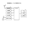
図1は、本実施例の無線端末である携帯電話機のハードウェア構成例を示す図である。図1において、本実施例の携帯電話機は、プロセッサ1,メモリ2,操作部3,表示部4,カメラ部5,マイク6,スピーカ7(イヤホンを含む),アンテナ8,無線通信部9,音声入出力部10を有する。
FIG. 1 is a diagram illustrating a hardware configuration example of a mobile phone which is a wireless terminal according to the present embodiment. In FIG. 1, the mobile phone of this embodiment includes a
メモリ2は、携帯電話機の各種機能を実行するためのデータを格納するROM(Read Only Memory)2−1と、各種機能を実行するための各種プログラムを格納するRAM(Random Access Memory)2−2とを有する。 The memory 2 includes a ROM (Read Only Memory) 2-1 for storing data for executing various functions of the mobile phone, and a RAM (Random Access Memory) 2-2 for storing various programs for executing various functions. And have.
プロセッサ1は、ROM2−1またはRAM2−2に格納された各種プログラムを実行するCPU(Central Processing Unit)等の演算処理部である。プロセッサ1は、ROM2−1またはRAM2−2に格納された各種プログラムを実行することにより、上述した操作部3,表示部4,カメラ部5,無線通信部9,音声入出力部10を制御する。なお、プロセッサ1で実行されるプログラムは、ROM2−1またはRAM2−2に格納されるだけではなく、CD(Compact Disc)−ROMやメモリ媒体等の頒布できる記憶媒体に記録しておき、記憶媒体から読み出して実行することができる。また、ネットワークを介して接続されたサーバにプログラムを格納し、サーバ上でプログラムが動作するようにしておき、ネットワークを介して接続される携帯電話機からの要求に応じて、サービスを要求元の携帯電話機に提供することもできる。
The
操作部3は、テンキーや操作ボタン等のユーザによる操作部である。表示部4は、LCD等のディスプレイである。また、表示部4には、文字や画像などの各種情報を表示する機能とともに、ユーザの各種操作の入力を受け付けるタッチパネル等の操作部3も併設されている。カメラ部5は、デジタルカメラ機能およびビデオ機能を有する。無線通信部9は、アンテナ8を介して音声や文字などの各種データの無線通信を行う。音声入出力部10は、マイク6を介して音声を入力するとともに、スピーカ7を介して音声を出力する入出力インターフェースである。
The
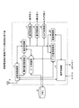
また、図2は、携帯電話機の機能ブロック構成例を示す図である。本実施例の携帯電話機は、警察や消防等へ緊急呼(110番や119番等)の発信を行うことにより、受理台との間に通話回線を確立する。なお、受理台とは、緊急呼を受け付けるコールセンタ内の電話機等である。また、コールセンタでは、受理台により通常の電話機能が使用できる他、インターネットに接続されたパーソナルコンピュータを使用してメール送受信等の処理を行うことができる。 FIG. 2 is a diagram illustrating a functional block configuration example of the mobile phone. The mobile phone according to the present embodiment establishes a telephone line with the receiving table by making an emergency call (110 or 119) to the police or fire department. The reception stand is a telephone in a call center that accepts an emergency call. In the call center, a normal telephone function can be used by the reception stand, and processing such as mail transmission / reception can be performed using a personal computer connected to the Internet.
また、本実施例の携帯電話機は、プロセッサ1がメモリ2から各種プログラムを読み出して実行することによって実現される機能ブロックとして、送受信制御部11と端末制御部12と音声制御部13とメール制御部14と圏内復旧制御部15とデータ通信制御部16と操作制御部17と表示制御部18とカメラ制御部19と録音制御部20を有する。
In addition, the mobile phone according to the present embodiment includes a transmission /
送受信制御部11は、アンテナ8を介して無線信号の送受信を行う。音声制御部13は、スピーカ7への音声出力処理およびマイク6からの音声入力処理を実行する。メール制御部14は、通常のメール送受信機能を有する。さらに、メール制御部14は、緊急呼通信時には、コールセンタからのメールを解析して受理台へ接続するための情報である接続先情報を抽出し、その接続先情報を端末制御部12に通知する。圏内復旧制御部15は、アンテナ8および送受信制御部11経由で受信した無線信号に基づいて携帯電話機の圏外/圏内を判断し、その旨を端末制御部12に通知する。端末制御部12は、携帯電話機における全体的な動作の制御、およびメモリ2に対する各種情報の読み出し/書き込みを行う。また、端末制御部12は、圏外により緊急呼が切断され、その後、圏内に復旧した場合に、メール制御部14より通知された接続先情報に基づいて元の受理台へ緊急呼を再接続する。データ通信制御部16は、IPプロトコル等のデータ通信機能を有し、送受信制御部11を介して受信したメールをメール制御部14へ転送する。
The transmission /
操作制御部17は、操作部3からのキー押下情報等を端末制御部12へイベントとして通知する。表示制御部18は、表示部4への表示を制御する。カメラ制御部19は、カメラ部5を制御し、撮影した画像および映像の情報をメモリ2へ保存する。録音制御部20は、音声制御部13を制御し、音声データをメモリ2へ保存する。
The
また、メモリ2には、上記受理台へ接続するための情報である接続先情報,画像および映像の情報,音声データの他、受信メールを認証するための送信元識別情報や、通話状態情報等が保存されている。メール制御部14は、コールセンタよりメールを受信した場合に、公開鍵等の送信元識別情報を用いてメール認証を行うことにより、メール送信元のなりすましを防止する。また、通話状態情報としては、緊急モードで受理台と通話中(緊急呼通信中)であることを示す情報である「緊急モード通話状態」,通常モードで動作中であることを示す情報である「通常モード通話状態」等が記録される。
Further, in the memory 2, in addition to connection destination information that is information for connecting to the receiving table, image and video information, audio data, transmission source identification information for authenticating received mail, call state information, and the like Is saved. When the
なお、上記携帯電話機の機能ブロック構成例は、説明の便宜上、本実施例の処理にかかわる構成を列挙したものであり、携帯電話機のすべての機能を表現したものではない。 Note that the functional block configuration example of the mobile phone described above enumerates the configuration related to the processing of this embodiment for convenience of explanation, and does not represent all the functions of the mobile phone.
また、図3は、コールセンタのハードウェア構成例を示すである。図3において、本実施例のコールセンタは、受理台21とメール送受信用のコンピュータ22−1,22−2,…,22−nとルータ23を有する。また、受理台21には、構内交換機25および電話機26−1,26−2,…,26−nが含まれている。なお、受理台21には、緊急呼の番号(110番,119番等)に加えて、電話機毎に、それぞれ固有の電話番号が割り振られているものとする。たとえば、受理台21の構内交換機25には、電話機と電話番号の対応表が記憶されており、固有の電話番号宛の着信があった場合には、この対応表に基づいて振り分けが行われる。
FIG. 3 shows a hardware configuration example of the call center. 3, the call center according to the present embodiment includes a receiving table 21, computers 22-1, 22-2,. The reception table 21 includes a
つづいて、本実施例の携帯電話機を含む無線通信システムの動作を図面に従って詳細に説明する。以下、本実施例では、緊急呼の一例として、携帯電話機のユーザが、警察へ110番通報を行う場合について説明する。なお、消防,救急への119番通報や、その他の緊急呼の発信についても同様に動作するものとする。 Next, the operation of the wireless communication system including the mobile phone of this embodiment will be described in detail with reference to the drawings. Hereinafter, in the present embodiment, a case where a user of a mobile phone makes a 110th report to the police will be described as an example of an emergency call. It should be noted that the 119 call to the fire and ambulance and other emergency calls are similarly operated.
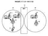
図4は、本実施例の無線通信システムの一例を示す図である。図4において、本実施例の無線通信システムは、F県警の110番の圏内である受信エリア34内に、上記図1および図2に示す携帯電話機である携帯電話機31と、携帯電話機31を収容する無線基地局32と、図3に示すコールセンタ内の受理台21であるF県警の受理台33−1〜33−nとを有する。また、本実施例の無線通信システムは、S県警の110番の圏内である受信エリア44内に、無線基地局42と、図3に示すコールセンタ内の受理台21であるS県警の受理台43とを有する。また、本実施例の無線通信システムは、受信エリア34,受信エリア44の他に、各エリアの間に110番の圏外であるトンネル等の圏外エリア51を有する。
FIG. 4 is a diagram illustrating an example of a wireless communication system according to the present embodiment. 4, the wireless communication system of the present embodiment accommodates the
上記のように構成された無線通信システムにおいて、F県警の受理台33−1〜33−nは、F県内の110番通報に対する処理を行い、S県警の受理台43は、S県内の110番通報に対する処理を行う。なお、受理台33−1〜33−n,受理台43内の電話機には、それぞれ固有の電話番号が割り振られているものとする。また、S県警の受理台は、複数であってもよい。
In the wireless communication system configured as described above, the F prefectural police reception bases 33-1 to 33-n perform processing for the 110th notification in the F prefecture, and the S prefectural
以下、本実施例では、受信エリア34に在圏する通報者が携帯電話機31を利用して110番通報を行い、携帯電話機31が、無線基地局32を介して、F県を管轄する受理台33−1と接続する場合を一例とする。
Hereinafter, in the present embodiment, a reporter who is in the
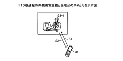
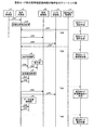
まず、本実施例の無線通信システムの動作として、携帯電話機31が、緊急呼を受理台33−1に接続する場合の動作について説明する。図5は、110番通報時の携帯電話機と受理台のやりとりを示す図である。本実施例では、一例として、接続先情報の受け渡しに電子メールを使用する。また、初期状態として、携帯電話機31のメモリ2には、通話状態情報として「通常モード通話状態」が記録されているものとする。
First, as an operation of the wireless communication system of the present embodiment, an operation when the
この状態で、通報者の携帯電話機31から110番の発信が行われ、コールセンタ内の受理台33−1が通報を受けた場合(S1)、コールセンタ内のオペレータが、発信元電話番号から発信元携帯電話機のメールアドレスを特定する。携帯電話機31は、110番の発信と同時に通常モードから緊急モードに遷移し、メモリ2内の通話状態情報を「緊急モード通話状態」に変更する。なお、メールアドレスの特定方法としては、たとえば、電話番号がそのままメールアドレスとなるSMS(Short Message Service)の利用が考えられる。また、その他の特定方法としては、以下の方法がある。まず、県警のサイトにおいて、緊急呼用のメールアドレスを予め公開しておく。そして、各ユーザが、自身の携帯電話機の電話番号とメールアドレスを含むメールを緊急呼用のメールアドレス宛に送信し、これらの情報を予め県警のサーバに登録しておく。この状態で、携帯電話機31が110番の発信を行い、受理台33−1が緊急呼を着信すると、コールセンタ内のオペレータが、県警のサーバから110番の発信元電話番号に対応するメールアドレスを検索し、特定する。これらの処理により、オペレータは、緊急呼発信元携帯電話機のメールアドレスを容易に特定することができる。
In this state, when the caller's
つぎに、オペレータは、コールセンタ内のコンピュータを使用して、上記で特定した携帯電話機31のメールアドレス宛に、受理台33−1へ接続するための接続先情報を含めたメールを送信する(S2)。そして、このメールを受信した携帯電話機31は、メールに含まれた接続先情報をメモリ2に保存する。これにより、携帯電話機31は、たとえば、圏外から圏内に復帰した場合に、メモリ2に保存しておいた接続先情報に基づいて、圏外へ移動する前に接続していた受理台33−1へ再接続することが可能となる。
Next, the operator uses a computer in the call center to send a mail including connection destination information for connecting to the receiving board 33-1 to the mail address of the
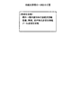
図6は、接続先情報の一例を示す図である。接続先情報には、圏外から圏内へ復帰後の接続先情報として、たとえば、受理台33−1内の電話機に割り当てられた固有の電話番号等の端末識別子を含める。なお、各受理台には、緊急呼の特番(110番等)とは別に、受理台内の電話機毎に固有の電話番号を割り当てることが可能であり、固有の電話番号による受理台への発呼が可能である。また、上記では、圏外から圏内へ復帰後の接続先情報として、受理台内の電話機の電話番号をメールに含めることとしたが、これに限らない。たとえば、回線の種類に応じて、DID(Direct Inward Dialing),SIP(Session Initiation Protocol)番号,IPアドレス等、を含めることとしてもよい。また、上記接続先情報を含めたメールには、オプションとして、さらに、画像,映像,音声等の送信先情報、およびメールの送信先情報(メールアドレス)を含めることとしてもよい。画像,映像,音声等の送信先情報としては、たとえば、IPアドレス,URL(Uniform Resource Locator)等が考えられる。 FIG. 6 is a diagram illustrating an example of connection destination information. The connection destination information includes, for example, a terminal identifier such as a unique telephone number assigned to the telephone set in the reception board 33-1 as the connection destination information after returning from outside the service area to the service area. In addition to the emergency call special number (110, etc.), each receiving table can be assigned a unique telephone number for each telephone in the receiving table. A call is possible. In the above description, the telephone number of the telephone in the reception table is included in the mail as the connection destination information after returning from outside the service area to the service area. However, the present invention is not limited to this. For example, DID (Direct Inward Dialing), SIP (Session Initiation Protocol) number, IP address, etc. may be included depending on the type of line. Further, the mail including the connection destination information may further include transmission destination information such as an image, video, and sound, and mail transmission destination information (mail address) as an option. For example, IP address, URL (Uniform Resource Locator), and the like can be considered as transmission destination information such as images, videos, and sounds.
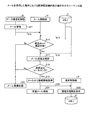
また、図7は、メールを受信した場合における携帯電話機31内部の動作を示すシーケンス図である。まず、アンテナ8,送受信制御部11を介してメールを受信したデータ通信制御部16では、そのメールをメール制御部14に転送する(S11,S12)。そして、メールを受け取ったメール制御部14は、メモリ2から現在の通話状態情報を読み出す(S13)。
FIG. 7 is a sequence diagram showing the internal operation of the
たとえば、現在の通話状態情報が「緊急モード通話状態」以外の場合(S14,No)、メール制御部14は、受け取ったメールが緊急呼に対する応答として送られてくるメール以外の通常メールであると判断し、通常のメール受信処理を実行する(S15)。一方、現在の通話状態情報が「緊急モード通話状態」の場合(S14,Yes)、メール制御部14は、メモリ2から送信元識別情報を読み出す(S16)。そして、メール制御部14は、送信元識別情報に基づいて、受け取ったメールが緊急呼に対する応答としてコールセンタ内のコンピュータから送られてきたメールであるかどうかを確認する(S17)。確認方法としては、たとえば、送信元識別子情報を鍵情報とし、公開鍵暗号方式や電子署名による復号が正常に行えるかによって、コールセンタ内のコンピュータから送られてきたメールであるかどうかを判断する。
For example, when the current call state information is other than “emergency mode call state” (S14, No), the
たとえば、緊急呼に対する応答としてコールセンタ内のコンピュータから送られてくるメール以外のメールの場合(S18,No)、メール制御部14は、通常のメール受信処理を実行する(S15)。一方、緊急呼に対する応答としてコールセンタ内のコンピュータから送られてきたメールの場合(S18,Yes)、メール制御部14は、そのメールから接続先情報を抽出する(S19)。そして、抽出した接続先情報を端末制御部12に通知し(S20)、その後、受信したメールを削除する(S21)。また、S20の処理で接続先情報を受信した端末制御部12は、その接続先情報をメモリ2に保存する(S22)。
For example, in the case of a mail other than mail sent from a computer in the call center as a response to an emergency call (S18, No), the
以上、上記図5および図7の動作を行うことにより、携帯電話機31は、F県を管轄する受理台33−1と接続するとともに、圏外から圏内に復帰した場合に受理台33−1へ再接続するための情報である接続先情報をメモリ2に保存する。なお、上記接続先情報をメモリ2に保存する処理は、110番通報後の「緊急モード通話状態」のときに実施されるものとするが、「緊急モード通話状態」移行後の、できるだけ早期に実施されることが望ましい。
As described above, by performing the operations shown in FIGS. 5 and 7, the
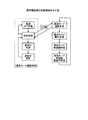
つづいて、携帯電話機31の状態遷移について説明する。図8は、携帯電話機31の状態遷移の示す図である。図8において、「通常モード通話状態」としては、「電源OFF状態」,「待受状態」,「発信中状態」,「通信中状態」の4つの状態がある。たとえば、「電源OFF状態」のときに操作部3の電源ボタンが押下された場合、携帯電話機31は「待受状態」に移行する。また、「待受状態」のときに操作部3の電源ボタンが押下された場合、携帯電話機31は「電源OFF状態」に移行する。また、「待受状態」のときに操作部3を用いてオフフックおよび電話番号入力が行われた場合、携帯電話機31は「発信中状態」に移行する。また、「発信中状態」のときにアンテナ8を介して相手装置から応答信号を受信した場合、携帯電話機31は「通話中状態」に移行する。また、「通話中状態」のときに操作部3を用いてオンフックが行われた場合、携帯電話機31は「待受状態」に移行する。なお、これら4つの状態の場合、メモリ2には、通話状態情報として「通常モード通話状態」が記録されている。
Next, the state transition of the
また、図8において、緊急モードとしては、「緊急モード通話状態」,「緊急モード圏外状態」,「緊急モード再接続状態」,「緊急モード再接続通話中状態」の4つの状態がある。たとえば、「待受状態」のときに操作部3を用いてオフフックおよび110番入力が行われた場合、携帯電話機31は「緊急モード通話状態」に移行する。この時点で、メモリ2には、通話状態情報として「緊急モード通話状態」が記録される。
In FIG. 8, the emergency mode includes four states of “emergency mode call state”, “emergency mode out-of-service state”, “emergency mode reconnection state”, and “emergency mode reconnection call state”. For example, when an off-hook and No. 110 input is performed using the
また、「緊急モード通話状態」のときに圏内復旧制御部15にて受信エリア34から圏外エリア51への移動が検知された場合、すなわち、緊急呼の通信が切断された場合、携帯電話機31は、「緊急モード圏外状態」に移行する。この時点で、メモリ2には、通話状態情報として「緊急モード圏外状態」が記録される。そして、携帯電話機31は、圏外中の音声,画像,映像の収集を開始する。
In addition, when the movement from the
また、「緊急モード圏外状態」のときに圏内復旧制御部15にて受信エリア34または受信エリア44への移動が検知された場合、携帯電話機31は、「緊急モード再接続状態」に移行する。この時点で、メモリ2には、通話状態情報として「緊急モード再接続状態」が記録される。そして、携帯電話機31は、自律的に、接続先情報として記録された電話番号による受理台33−1への発呼を行う。
Further, when movement to the
また、「緊急モード再接続状態」のときにアンテナ8を介して受理台33−1から応答信号を受信した場合、携帯電話機31は、「緊急モード再接続通話中状態」に移行する。この時点で、メモリ2には、通話状態情報として「緊急モード再接続通信中状態」が記録される。そして、携帯電話機31は、音声,画像,映像の収集を停止する。また、携帯電話機31は、アンテナ8を介して、収集した音声,画像,映像の情報をコールセンタ宛に送信する。この送信は、たとえば、メモリ2に記録された接続先情報に含まれた、画像,映像,音声等の送信先情報に基づいて行われる。
When a response signal is received from the receiving board 33-1 via the antenna 8 in the “emergency mode reconnection state”, the
また、「緊急モード再接続通話中状態」のときに上記音声,画像,映像の情報の送信が完了した場合、携帯電話機31は、「緊急モード通話状態」に戻る。この時点で、メモリ2には、通話状態情報として「緊急モード通話状態」が記録される。そして、この状態で、通報者は、受理台33−1のオペレータとの通話を再開する。
In addition, when the transmission of the voice, image, and video information is completed in the “emergency mode reconnection call state”, the
また、「緊急モード通話状態」のときに操作部3を用いてオンフックが行われた場合、携帯電話機31は、「待受状態」に移行する。この時点で、メモリ2には、通話状態情報として「通常モード通話状態」が記録される。
Further, when the on-hook is performed using the
図9は、上記緊急モード時の携帯電話機31内部の動作を示すシーケンス図である。なお、図9では、すでに携帯電話機31により110番通報が実施されており、端末制御部12が、メモリ2内の通話状態情報を「通常モード通話状態」から「緊急モード通話状態」に変更済みであることを前提とする。
FIG. 9 is a sequence diagram showing the internal operation of the
まず、メール制御部14は、図3に示すコールセンタ内のコンピュータからの受信メールから接続先情報を抽出し、抽出した接続先情報を端末制御部12に通知する(S31、図7のS20参照)。つぎに、接続先情報を受け取った端末制御部12は、その接続先情報をメモリ2に保存する(S32、図7のS22参照)。
First, the
この状態において、圏内復旧制御部15が受信エリア34から圏外エリア51への自機の移動を検知した場合、圏内復旧制御部15では、端末制御部12に対し、自機が圏外エリア51に移動したことを通知する(S33)。端末制御部12は、メモリ2内の通話状態情報を「緊急モード通話状態」から「緊急モード圏外状態」に変更する(S34)。
In this state, when the in-zone
つぎに、端末制御部12は、録音制御部20に対して音声の録音を指示し(S35)、さらに、カメラ制御部19に対して画像および映像(動画)の撮影を指示する(S36)。そして、録音制御部20は、音声制御部13を介して録音した音声データをメモリ2に保存する。また、カメラ制御部19は、カメラ部5で撮影された画像および映像の情報をメモリ2に保存する。なお、本実施例では、音声の録音および画像,映像の撮影を行うことにより圏外中の情報を収集しているが、これに限らず、音声,画像,映像の少なくともいずれか1つの情報を収集することとしてもよい。また、圏外中にこれらの情報を収集しないこととしてもよい。
Next, the
その後、圏内復旧制御部15が圏外エリア51から圏内、すなわち、受信エリア34または受信エリア44への自機の移動を検知した場合、圏内復旧制御部15では、端末制御部12に対し、自機が圏内に移動したことを通知する(S37)。端末制御部12は、メモリ2内の通話状態情報を「緊急モード圏外状態」から「緊急モード再接続状態」に変更する(S38)。
Thereafter, when the area
つぎに、端末制御部12は、表示制御部18に対して110番の発呼画面表示を指示する(S39)。そして、表示制御部18は、発呼画面表示の指示に従い、表示部4に対し、110番の発呼であることを表示するための制御を行う(S40)。同時に、端末制御部12は、送受信制御部11を介して、メモリ2内の接続先情報に含まれる電話番号による受理台33−1への発呼を行う(S41)。そして、端末制御部12は、送受信制御部11を介して、受理台33−1から応答信号を受信する(S42)。これにより、携帯電話機31と受理台33−1との間の回線が接続される。携帯電話機31と受理台33−1との間の回線が接続されると、端末制御部12は、メモリ2内の通話状態情報を「緊急モード再接続状態」から「緊急モード再接続通話中状態」に変更する(S43)。
Next, the
つぎに、端末制御部12は、録音制御部20に対して音声の録音停止を指示し(S44)、さらに、カメラ制御部19に対して画像および映像(動画)の撮影停止を指示する(S45)。また、端末制御部12は、データ通信制御部16を制御して、メモリ2に保存された音声,画像,映像の情報を、接続先情報に含まれた所定の送信先宛に送信する(S46)。これにより、受理台33−1のオペレータは、コールセンタ内のコンピュータを介して、圏外中の携帯電話機31の周辺の状況を知ることができる。そして、端末制御部12は、データ通信制御部16から音声,画像,映像の情報の送信完了を受け取った場合に(S47)、メモリ2内の通話状態情報を「緊急モード再接続通話中状態」から「緊急モード通話状態」に変更する(S48)。
Next, the
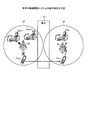
つづいて、図面を用いて従来の無線通信システムと本実施例の無線通信システムにおける動作の違いを説明する。図10は、従来の無線通信システムの動作例を示す図であり、詳細には、従来の携帯電話機31aが受信エリア34から圏外エリア51を経由して受信エリア44へ移動した場合を示している。なお、図10では、受信エリア34に在圏する通報者が従来の携帯電話機31aを利用して110番通報を行い、携帯電話機31aが、無線基地局32を介して、F県を管轄する受理台33a−1〜33a−nのうちの受理台33a−1と接続している場合を想定する。
Next, differences in operation between the conventional wireless communication system and the wireless communication system of the present embodiment will be described with reference to the drawings. FIG. 10 is a diagram illustrating an operation example of the conventional wireless communication system, and more specifically, shows a case where the conventional
この状態で、通報者が圏外エリア51に移動すると、携帯電話機31aと受理台33a−1との間の通話回線が切断される。すなわち、通報者と受理台のオペレータとの会話が切断される。また、通話回線の切断に伴い、受理台33a−1では、オペレータの操作によりオンフックが行われる。その後、通報者がさらに圏外エリア51から受信エリア44に移動し、携帯電話機31aが圏内に復帰した場合、通報者は、受理台33a−1のオペレータとの会話を再開するために、受信エリア44内で携帯電話機31aを用いて再度110番通報を行う。しかしながら、従来の無線通信システムにおいては、携帯電話機31aは、圏外へ移動する前の受信エリア34内の受理台33a−1には接続されず、図10に示すように、無線基地局42を介してS県を管轄する受理台43aに接続されてしまう。すなわち、従来の携帯電話機31aは、圏外へ移動する前に接続されていた受理台33a−1と再接続することはできない。
In this state, when the reporter moves to the out-of-
一方、本実施例では、受理台33−1と通話中の携帯電話機31が、受信エリア34から圏外エリア51を経由して受信エリア44へ移動した場合に、受信エリア44内において、元の受信エリア34内の受理台33−1と再接続することを可能とした。
On the other hand, in the present embodiment, when the
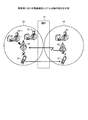
図11は、本実施例の無線通信システムの動作例を示す図であり、詳細には、携帯電話機31が受信エリア34から圏外エリア51を経由して受信エリア44へ移動した場合を示している。
FIG. 11 is a diagram illustrating an operation example of the wireless communication system according to the present embodiment. Specifically, the
具体的には、携帯電話機31が、上記図7に示すとおり、「緊急モード通話状態」において、図3に示すコールセンタ内のコンピュータから送られてくる接続先情報をメモリ2に保存する。そして、携帯電話機31は、圏外エリア51への移動により受理台33−1との通話回線が切断され、その後、受信エリア44に復帰した場合に、受理台33−1と再接続するために、上記図9に示すとおり、受理台33−1の電話番号による発呼を行う。これにより、携帯電話機31は、図11に示すように、無線基地局42,無線基地局32を介して、圏外に移動する前に接続していた受理台33−1と再接続することが可能となる。なお、本実施例では、たとえば、携帯電話機31が受信エリア34から圏外エリア51を経由して再度受信エリア34へ移動した場合についても、携帯電話機31が、受理台33−1の電話番号による発呼を行うことで、受理台33−1との再接続が可能となる。
Specifically, as shown in FIG. 7, the
上述してきたように、本実施例では、携帯電話機31が、自身が発信した緊急呼が接続された受理台33−1を含むコールセンタ内のコンピュータから、受理台33−1へ接続するための情報である接続先情報を受信して保存しておく。そして、携帯電話機31は、移動により圏外で通話が長時間切断した後に、圏内復帰で再接続を行う場合に、上記接続先情報に基づいて受理台33−1へ緊急呼の発信を行うこととした。これにより、携帯電話機31は、圏外へ移動する前に接続されていた受理台33−1との緊急呼の再接続を可能とする。
As described above, in the present embodiment, the
1 プロセッサ
2 メモリ
3 操作部
4 表示部
5 カメラ部
6 マイク
7 スピーカ
8 アンテナ
9 無線通信部
10 音声入出力部
11 送受信制御部
12 端末制御部
13 音声制御部
14 メール制御部
15 圏内復旧制御部
16 データ通信制御部
17 操作制御部
18 表示制御部
19 カメラ制御部
20 録音制御部
21 受理台
22−1,22−2,22−n コンピュータ
23 ルータ
25 構内交換機
26−1,26−2,26−n 電話機
DESCRIPTION OF
Claims (2)
記憶部と、
緊急呼の発信があった場合に、前記記憶部に記憶されている通話状態を緊急モード通話状態に変更し、前記通話状態が緊急モード通話状態である自端末が無線エリアの圏外に移動した後に再度無線エリアの圏内に移動した場合に、前記通話状態を緊急モード再接続状態に変更する端末制御部と、
メールの受信に応じて、前記通話状態が緊急モード通話状態であるか否かを判定し、緊急モード通話状態であった場合に、前記メールに含まれる端末識別子を抽出して前記記憶部に記憶させるメール制御部と、
を備え、
前記端末制御部は、
前記通話状態が緊急モード再接続状態に変更されたことに応じ、前記端末識別子を指定した発呼を行う、
ことを特徴とする無線端末。 A wireless terminal,
A storage unit;
When an emergency call is made, the call state stored in the storage unit is changed to the emergency mode call state, and the terminal whose call state is the emergency mode call state moves out of the wireless area. A terminal control unit that changes the call state to an emergency mode reconnection state when moving into a wireless area again;
In response to the reception of the mail, it is determined whether or not the call state is an emergency mode call state. If the call state is the emergency mode call state, a terminal identifier included in the mail is extracted and stored in the storage unit An email control unit
With
The terminal control unit
In response to the call state being changed to the emergency mode reconnection state, making a call specifying the terminal identifier;
A wireless terminal characterized by that.
前記通話状態が緊急モード通話状態である自端末が前記無線エリアの圏外に移動した場合に、音声、画像、映像の少なくともいずれか1つの情報を収集し、
その後、前記無線端末が前記無線エリアの圏内に移動して前記端末識別子を指定した発呼を行った場合に、収集した前記情報を前記メールの送信元に送信する、
ことを特徴とする請求項1に記載の無線端末。 The mail control unit
When the terminal whose call state is the emergency mode call state moves out of the wireless area, it collects at least one information of voice, image, video,
Then, when the wireless terminal moves within the wireless area and makes a call specifying the terminal identifier, the collected information is transmitted to the sender of the mail.
The wireless terminal according to claim 1.
Priority Applications (1)
| Application Number | Priority Date | Filing Date | Title |
|---|---|---|---|
| JP2011121018A JP5664458B2 (en) | 2011-05-30 | 2011-05-30 | Wireless terminal |
Applications Claiming Priority (1)
| Application Number | Priority Date | Filing Date | Title |
|---|---|---|---|
| JP2011121018A JP5664458B2 (en) | 2011-05-30 | 2011-05-30 | Wireless terminal |
Publications (2)
| Publication Number | Publication Date |
|---|---|
| JP2012249197A JP2012249197A (en) | 2012-12-13 |
| JP5664458B2 true JP5664458B2 (en) | 2015-02-04 |
Family
ID=47469190
Family Applications (1)
| Application Number | Title | Priority Date | Filing Date |
|---|---|---|---|
| JP2011121018A Active JP5664458B2 (en) | 2011-05-30 | 2011-05-30 | Wireless terminal |
Country Status (1)
| Country | Link |
|---|---|
| JP (1) | JP5664458B2 (en) |
Families Citing this family (2)
| Publication number | Priority date | Publication date | Assignee | Title |
|---|---|---|---|---|
| US9814081B2 (en) | 2013-08-02 | 2017-11-07 | Mediatek Inc. | Methods for processing emergency call and communications apparatuses utilizing the same |
| JP6731316B2 (en) * | 2016-08-31 | 2020-07-29 | 株式会社日立製作所 | Notification reception system and notification reception method |
Family Cites Families (4)
| Publication number | Priority date | Publication date | Assignee | Title |
|---|---|---|---|---|
| JP3012614B1 (en) * | 1998-10-16 | 2000-02-28 | 静岡日本電気株式会社 | Mobile communication system, mobile terminal used therefor, and reconnection method |
| JP2003169165A (en) * | 2001-11-30 | 2003-06-13 | Nec Corp | Mobile communication terminal, emergency call system, emergency call transmitting method for mobile communication terminal and program therefor |
| JP2003217060A (en) * | 2002-01-21 | 2003-07-31 | Nec Commun Syst Ltd | Crime preventive system using cellular phone |
| JP4451840B2 (en) * | 2005-12-27 | 2010-04-14 | 富士通株式会社 | Location information notification method and emergency call system when calling from a mobile terminal to an emergency call destination |
-
2011
- 2011-05-30 JP JP2011121018A patent/JP5664458B2/en active Active
Also Published As
| Publication number | Publication date |
|---|---|
| JP2012249197A (en) | 2012-12-13 |
Similar Documents
| Publication | Publication Date | Title |
|---|---|---|
| CN103139529B (en) | Video call switching method between sip server, video call device | |
| US9041763B2 (en) | Method for establishing video conference | |
| US8254532B2 (en) | Network videoconference equipment and its method of proceeding network videoconference | |
| US20070263613A1 (en) | System for connecting information processing devices associated with IP telephones | |
| CN105611055B (en) | Call method and device | |
| US20070123224A1 (en) | Information processing method and system for preventing leakage of information from mobile phone | |
| JP2012050137A (en) | User interface for communication device | |
| US8494123B2 (en) | On-hold visual menu from a user's communications device | |
| CN101848445B (en) | Instant messaging method and device | |
| CN111432386B (en) | Connection switching method, device, equipment and storage medium of Bluetooth headset | |
| JP2005124183A (en) | Device and method for sending identification information of a plurality of communication devices active on communication session to information receiving component | |
| CN105915521A (en) | Multi-party communication management method, device and terminal | |
| JP2006270166A (en) | Visual communication server, visual communication program, and visual communication method | |
| JP5664458B2 (en) | Wireless terminal | |
| US20140295801A1 (en) | Image response system and method of forming same | |
| JP4229774B2 (en) | Session control program and communication terminal device | |
| US20110201315A1 (en) | Providing web-activated callback by just dialling and pressing the call button | |
| JP5802116B2 (en) | Call system with data sharing function | |
| CN101115097B (en) | Call center system for video phone communication | |
| JP6645608B1 (en) | Telephone terminal, extension telephone system, computer readable program, and method of notifying incoming call from door phone with camera | |
| JP4628919B2 (en) | Communication apparatus and communication method | |
| CN106657533B (en) | Call handling method and device | |
| KR100850573B1 (en) | Mobile terminal for ptt and method for executing missed ptt call information thereof | |
| JP2015213270A (en) | Communication server | |
| JP6602919B2 (en) | Communication server |
Legal Events
| Date | Code | Title | Description |
|---|---|---|---|
| A621 | Written request for application examination |
Free format text: JAPANESE INTERMEDIATE CODE: A621 Effective date: 20140304 |
|
| A977 | Report on retrieval |
Free format text: JAPANESE INTERMEDIATE CODE: A971007 Effective date: 20141030 |
|
| TRDD | Decision of grant or rejection written | ||
| A01 | Written decision to grant a patent or to grant a registration (utility model) |
Free format text: JAPANESE INTERMEDIATE CODE: A01 Effective date: 20141111 |
|
| A61 | First payment of annual fees (during grant procedure) |
Free format text: JAPANESE INTERMEDIATE CODE: A61 Effective date: 20141124 |
|
| R150 | Certificate of patent or registration of utility model |
Ref document number: 5664458 Country of ref document: JP Free format text: JAPANESE INTERMEDIATE CODE: R150 |
|
| S111 | Request for change of ownership or part of ownership |
Free format text: JAPANESE INTERMEDIATE CODE: R313113 |
|
| R350 | Written notification of registration of transfer |
Free format text: JAPANESE INTERMEDIATE CODE: R350 |
|
| R250 | Receipt of annual fees |
Free format text: JAPANESE INTERMEDIATE CODE: R250 |
|
| S531 | Written request for registration of change of domicile |
Free format text: JAPANESE INTERMEDIATE CODE: R313531 |
|
| S533 | Written request for registration of change of name |
Free format text: JAPANESE INTERMEDIATE CODE: R313533 |
|
| R350 | Written notification of registration of transfer |
Free format text: JAPANESE INTERMEDIATE CODE: R350 |
|
| R250 | Receipt of annual fees |
Free format text: JAPANESE INTERMEDIATE CODE: R250 |
|
| R250 | Receipt of annual fees |
Free format text: JAPANESE INTERMEDIATE CODE: R250 |
|
| R250 | Receipt of annual fees |
Free format text: JAPANESE INTERMEDIATE CODE: R250 |
|
| S111 | Request for change of ownership or part of ownership |
Free format text: JAPANESE INTERMEDIATE CODE: R313113 |
|
| S533 | Written request for registration of change of name |
Free format text: JAPANESE INTERMEDIATE CODE: R313533 |