JP5662683B2 - Apparatus and method for deploying an implantable device in a body - Google Patents
Apparatus and method for deploying an implantable device in a body Download PDFInfo
- Publication number
- JP5662683B2 JP5662683B2 JP2009549294A JP2009549294A JP5662683B2 JP 5662683 B2 JP5662683 B2 JP 5662683B2 JP 2009549294 A JP2009549294 A JP 2009549294A JP 2009549294 A JP2009549294 A JP 2009549294A JP 5662683 B2 JP5662683 B2 JP 5662683B2
- Authority
- JP
- Japan
- Prior art keywords
- stent
- lumen
- catheter
- side branch
- string
- Prior art date
- Legal status (The legal status is an assumption and is not a legal conclusion. Google has not performed a legal analysis and makes no representation as to the accuracy of the status listed.)
- Active
Links
- 238000000034 method Methods 0.000 title description 69
- 239000000463 material Substances 0.000 claims description 53
- 230000007246 mechanism Effects 0.000 claims description 30
- 230000033001 locomotion Effects 0.000 claims description 20
- 239000012530 fluid Substances 0.000 claims description 19
- 238000011068 loading method Methods 0.000 claims description 15
- 229910000679 solder Inorganic materials 0.000 claims description 5
- 230000000717 retained effect Effects 0.000 claims description 2
- 238000009941 weaving Methods 0.000 claims description 2
- 230000003247 decreasing effect Effects 0.000 claims 1
- 238000002513 implantation Methods 0.000 description 60
- 210000004027 cell Anatomy 0.000 description 33
- 210000002376 aorta thoracic Anatomy 0.000 description 32
- 239000007943 implant Substances 0.000 description 30
- 210000005166 vasculature Anatomy 0.000 description 30
- 210000001519 tissue Anatomy 0.000 description 27
- 210000001367 artery Anatomy 0.000 description 26
- 230000017531 blood circulation Effects 0.000 description 22
- 210000004204 blood vessel Anatomy 0.000 description 19
- 210000002744 extracellular matrix Anatomy 0.000 description 19
- 102000010834 Extracellular Matrix Proteins Human genes 0.000 description 18
- 108010037362 Extracellular Matrix Proteins Proteins 0.000 description 18
- 230000002792 vascular Effects 0.000 description 15
- 239000010410 layer Substances 0.000 description 14
- 210000004876 tela submucosa Anatomy 0.000 description 14
- 210000000709 aorta Anatomy 0.000 description 13
- 239000008280 blood Substances 0.000 description 12
- 210000004369 blood Anatomy 0.000 description 12
- BASFCYQUMIYNBI-UHFFFAOYSA-N platinum Chemical compound [Pt] BASFCYQUMIYNBI-UHFFFAOYSA-N 0.000 description 10
- 230000002829 reductive effect Effects 0.000 description 10
- 238000013519 translation Methods 0.000 description 10
- 206010002329 Aneurysm Diseases 0.000 description 9
- 210000002469 basement membrane Anatomy 0.000 description 9
- 239000003814 drug Substances 0.000 description 9
- 239000000203 mixture Substances 0.000 description 9
- 238000011282 treatment Methods 0.000 description 9
- 210000001765 aortic valve Anatomy 0.000 description 8
- 238000000576 coating method Methods 0.000 description 8
- 230000023597 hemostasis Effects 0.000 description 8
- 238000003384 imaging method Methods 0.000 description 8
- 230000001936 parietal effect Effects 0.000 description 7
- 239000004480 active ingredient Substances 0.000 description 6
- 230000008901 benefit Effects 0.000 description 6
- 238000013461 design Methods 0.000 description 6
- 230000006870 function Effects 0.000 description 6
- 210000003128 head Anatomy 0.000 description 6
- 238000002608 intravascular ultrasound Methods 0.000 description 6
- 230000002262 irrigation Effects 0.000 description 6
- 238000003973 irrigation Methods 0.000 description 6
- 210000000056 organ Anatomy 0.000 description 6
- 238000004804 winding Methods 0.000 description 6
- FAPWRFPIFSIZLT-UHFFFAOYSA-M Sodium chloride Chemical compound [Na+].[Cl-] FAPWRFPIFSIZLT-UHFFFAOYSA-M 0.000 description 5
- 210000003484 anatomy Anatomy 0.000 description 5
- 210000001168 carotid artery common Anatomy 0.000 description 5
- 239000011248 coating agent Substances 0.000 description 5
- 229940079593 drug Drugs 0.000 description 5
- 210000001105 femoral artery Anatomy 0.000 description 5
- 230000036961 partial effect Effects 0.000 description 5
- 229910052697 platinum Inorganic materials 0.000 description 5
- 238000012545 processing Methods 0.000 description 5
- 210000000813 small intestine Anatomy 0.000 description 5
- 239000011780 sodium chloride Substances 0.000 description 5
- 238000010186 staining Methods 0.000 description 5
- 210000003270 subclavian artery Anatomy 0.000 description 5
- 230000001225 therapeutic effect Effects 0.000 description 5
- 208000019553 vascular disease Diseases 0.000 description 5
- 102000008186 Collagen Human genes 0.000 description 4
- 108010035532 Collagen Proteins 0.000 description 4
- QTBSBXVTEAMEQO-UHFFFAOYSA-N acetic acid Substances CC(O)=O QTBSBXVTEAMEQO-UHFFFAOYSA-N 0.000 description 4
- 230000008321 arterial blood flow Effects 0.000 description 4
- 230000008859 change Effects 0.000 description 4
- 229920001436 collagen Polymers 0.000 description 4
- 238000004891 communication Methods 0.000 description 4
- 210000002919 epithelial cell Anatomy 0.000 description 4
- PCHJSUWPFVWCPO-UHFFFAOYSA-N gold Chemical compound [Au] PCHJSUWPFVWCPO-UHFFFAOYSA-N 0.000 description 4
- 229910052737 gold Inorganic materials 0.000 description 4
- 239000010931 gold Substances 0.000 description 4
- 238000011065 in-situ storage Methods 0.000 description 4
- 210000002414 leg Anatomy 0.000 description 4
- 230000000670 limiting effect Effects 0.000 description 4
- 238000004519 manufacturing process Methods 0.000 description 4
- 229910001000 nickel titanium Inorganic materials 0.000 description 4
- -1 polytetrafluoroethylene Polymers 0.000 description 4
- 238000002360 preparation method Methods 0.000 description 4
- 239000000758 substrate Substances 0.000 description 4
- 229940124597 therapeutic agent Drugs 0.000 description 4
- 102000004190 Enzymes Human genes 0.000 description 3
- 108090000790 Enzymes Proteins 0.000 description 3
- WQZGKKKJIJFFOK-GASJEMHNSA-N Glucose Natural products OC[C@H]1OC(O)[C@H](O)[C@@H](O)[C@@H]1O WQZGKKKJIJFFOK-GASJEMHNSA-N 0.000 description 3
- QVGXLLKOCUKJST-UHFFFAOYSA-N atomic oxygen Chemical compound [O] QVGXLLKOCUKJST-UHFFFAOYSA-N 0.000 description 3
- 230000036772 blood pressure Effects 0.000 description 3
- 239000003795 chemical substances by application Substances 0.000 description 3
- 238000004140 cleaning Methods 0.000 description 3
- 210000002808 connective tissue Anatomy 0.000 description 3
- 230000007423 decrease Effects 0.000 description 3
- 210000004207 dermis Anatomy 0.000 description 3
- 229940088598 enzyme Drugs 0.000 description 3
- 210000000981 epithelium Anatomy 0.000 description 3
- 230000002496 gastric effect Effects 0.000 description 3
- 239000008103 glucose Substances 0.000 description 3
- 238000000227 grinding Methods 0.000 description 3
- 210000004185 liver Anatomy 0.000 description 3
- 230000014759 maintenance of location Effects 0.000 description 3
- 210000004379 membrane Anatomy 0.000 description 3
- 239000012528 membrane Substances 0.000 description 3
- 229910052751 metal Inorganic materials 0.000 description 3
- 239000002184 metal Substances 0.000 description 3
- 230000005012 migration Effects 0.000 description 3
- 238000013508 migration Methods 0.000 description 3
- 210000004877 mucosa Anatomy 0.000 description 3
- 210000004400 mucous membrane Anatomy 0.000 description 3
- 239000001301 oxygen Substances 0.000 description 3
- 229910052760 oxygen Inorganic materials 0.000 description 3
- 239000002245 particle Substances 0.000 description 3
- 239000000843 powder Substances 0.000 description 3
- 230000008569 process Effects 0.000 description 3
- 230000008439 repair process Effects 0.000 description 3
- 239000000243 solution Substances 0.000 description 3
- 239000000126 substance Substances 0.000 description 3
- 238000012800 visualization Methods 0.000 description 3
- XLYOFNOQVPJJNP-UHFFFAOYSA-N water Substances O XLYOFNOQVPJJNP-UHFFFAOYSA-N 0.000 description 3
- IJGRMHOSHXDMSA-UHFFFAOYSA-N Atomic nitrogen Chemical compound N#N IJGRMHOSHXDMSA-UHFFFAOYSA-N 0.000 description 2
- PXHVJJICTQNCMI-UHFFFAOYSA-N Nickel Chemical compound [Ni] PXHVJJICTQNCMI-UHFFFAOYSA-N 0.000 description 2
- HZEWFHLRYVTOIW-UHFFFAOYSA-N [Ti].[Ni] Chemical compound [Ti].[Ni] HZEWFHLRYVTOIW-UHFFFAOYSA-N 0.000 description 2
- 208000002223 abdominal aortic aneurysm Diseases 0.000 description 2
- 230000003187 abdominal effect Effects 0.000 description 2
- 230000009471 action Effects 0.000 description 2
- 238000002399 angioplasty Methods 0.000 description 2
- 210000000702 aorta abdominal Anatomy 0.000 description 2
- TZCXTZWJZNENPQ-UHFFFAOYSA-L barium sulfate Chemical compound [Ba+2].[O-]S([O-])(=O)=O TZCXTZWJZNENPQ-UHFFFAOYSA-L 0.000 description 2
- 238000005452 bending Methods 0.000 description 2
- 238000002591 computed tomography Methods 0.000 description 2
- 230000008602 contraction Effects 0.000 description 2
- 238000005520 cutting process Methods 0.000 description 2
- 201000010099 disease Diseases 0.000 description 2
- 208000037265 diseases, disorders, signs and symptoms Diseases 0.000 description 2
- 230000002526 effect on cardiovascular system Effects 0.000 description 2
- 230000003073 embolic effect Effects 0.000 description 2
- 230000003511 endothelial effect Effects 0.000 description 2
- 239000004744 fabric Substances 0.000 description 2
- 239000000835 fiber Substances 0.000 description 2
- 238000002594 fluoroscopy Methods 0.000 description 2
- 238000009472 formulation Methods 0.000 description 2
- 210000003709 heart valve Anatomy 0.000 description 2
- 210000000936 intestine Anatomy 0.000 description 2
- 239000004816 latex Substances 0.000 description 2
- 229920000126 latex Polymers 0.000 description 2
- 239000011159 matrix material Substances 0.000 description 2
- 238000005259 measurement Methods 0.000 description 2
- HLXZNVUGXRDIFK-UHFFFAOYSA-N nickel titanium Chemical compound [Ti].[Ti].[Ti].[Ti].[Ti].[Ti].[Ti].[Ti].[Ti].[Ti].[Ti].[Ni].[Ni].[Ni].[Ni].[Ni].[Ni].[Ni].[Ni].[Ni].[Ni].[Ni].[Ni].[Ni].[Ni] HLXZNVUGXRDIFK-UHFFFAOYSA-N 0.000 description 2
- RVTZCBVAJQQJTK-UHFFFAOYSA-N oxygen(2-);zirconium(4+) Chemical compound [O-2].[O-2].[Zr+4] RVTZCBVAJQQJTK-UHFFFAOYSA-N 0.000 description 2
- 229920001296 polysiloxane Polymers 0.000 description 2
- 229920002635 polyurethane Polymers 0.000 description 2
- 239000004814 polyurethane Substances 0.000 description 2
- 108090000765 processed proteins & peptides Proteins 0.000 description 2
- 238000003672 processing method Methods 0.000 description 2
- 230000005855 radiation Effects 0.000 description 2
- 230000009467 reduction Effects 0.000 description 2
- 230000003014 reinforcing effect Effects 0.000 description 2
- 210000002254 renal artery Anatomy 0.000 description 2
- 238000000926 separation method Methods 0.000 description 2
- 210000003491 skin Anatomy 0.000 description 2
- 210000002460 smooth muscle Anatomy 0.000 description 2
- 239000007787 solid Substances 0.000 description 2
- 229910001220 stainless steel Inorganic materials 0.000 description 2
- 239000010935 stainless steel Substances 0.000 description 2
- 210000000130 stem cell Anatomy 0.000 description 2
- 239000000725 suspension Substances 0.000 description 2
- 229910052715 tantalum Inorganic materials 0.000 description 2
- GUVRBAGPIYLISA-UHFFFAOYSA-N tantalum atom Chemical compound [Ta] GUVRBAGPIYLISA-UHFFFAOYSA-N 0.000 description 2
- 238000005406 washing Methods 0.000 description 2
- TUSDEZXZIZRFGC-UHFFFAOYSA-N 1-O-galloyl-3,6-(R)-HHDP-beta-D-glucose Natural products OC1C(O2)COC(=O)C3=CC(O)=C(O)C(O)=C3C3=C(O)C(O)=C(O)C=C3C(=O)OC1C(O)C2OC(=O)C1=CC(O)=C(O)C(O)=C1 TUSDEZXZIZRFGC-UHFFFAOYSA-N 0.000 description 1
- 108020000948 Antisense Oligonucleotides Proteins 0.000 description 1
- 208000031104 Arterial Occlusive disease Diseases 0.000 description 1
- 206010060965 Arterial stenosis Diseases 0.000 description 1
- BSYNRYMUTXBXSQ-UHFFFAOYSA-N Aspirin Chemical compound CC(=O)OC1=CC=CC=C1C(O)=O BSYNRYMUTXBXSQ-UHFFFAOYSA-N 0.000 description 1
- 108010006654 Bleomycin Proteins 0.000 description 1
- 102000016289 Cell Adhesion Molecules Human genes 0.000 description 1
- 108010067225 Cell Adhesion Molecules Proteins 0.000 description 1
- 229940123587 Cell cycle inhibitor Drugs 0.000 description 1
- 229910000684 Cobalt-chrome Inorganic materials 0.000 description 1
- 229920004934 Dacron® Polymers 0.000 description 1
- 208000005189 Embolism Diseases 0.000 description 1
- 239000001263 FEMA 3042 Substances 0.000 description 1
- 208000009087 False Aneurysm Diseases 0.000 description 1
- 102000009123 Fibrin Human genes 0.000 description 1
- 108010073385 Fibrin Proteins 0.000 description 1
- BWGVNKXGVNDBDI-UHFFFAOYSA-N Fibrin monomer Chemical compound CNC(=O)CNC(=O)CN BWGVNKXGVNDBDI-UHFFFAOYSA-N 0.000 description 1
- 102000008946 Fibrinogen Human genes 0.000 description 1
- 108010049003 Fibrinogen Proteins 0.000 description 1
- 102000016359 Fibronectins Human genes 0.000 description 1
- 108010067306 Fibronectins Proteins 0.000 description 1
- 102000003886 Glycoproteins Human genes 0.000 description 1
- 108090000288 Glycoproteins Proteins 0.000 description 1
- HTTJABKRGRZYRN-UHFFFAOYSA-N Heparin Chemical compound OC1C(NC(=O)C)C(O)OC(COS(O)(=O)=O)C1OC1C(OS(O)(=O)=O)C(O)C(OC2C(C(OS(O)(=O)=O)C(OC3C(C(O)C(O)C(O3)C(O)=O)OS(O)(=O)=O)C(CO)O2)NS(O)(=O)=O)C(C(O)=O)O1 HTTJABKRGRZYRN-UHFFFAOYSA-N 0.000 description 1
- 108090000100 Hepatocyte Growth Factor Proteins 0.000 description 1
- 102000003745 Hepatocyte Growth Factor Human genes 0.000 description 1
- 241000124008 Mammalia Species 0.000 description 1
- 229930192392 Mitomycin Natural products 0.000 description 1
- NWIBSHFKIJFRCO-WUDYKRTCSA-N Mytomycin Chemical compound C1N2C(C(C(C)=C(N)C3=O)=O)=C3[C@@H](COC(N)=O)[C@@]2(OC)[C@@H]2[C@H]1N2 NWIBSHFKIJFRCO-WUDYKRTCSA-N 0.000 description 1
- MWUXSHHQAYIFBG-UHFFFAOYSA-N Nitric oxide Chemical class O=[N] MWUXSHHQAYIFBG-UHFFFAOYSA-N 0.000 description 1
- 229930012538 Paclitaxel Natural products 0.000 description 1
- 241001494479 Pecora Species 0.000 description 1
- LRBQNJMCXXYXIU-PPKXGCFTSA-N Penta-digallate-beta-D-glucose Natural products OC1=C(O)C(O)=CC(C(=O)OC=2C(=C(O)C=C(C=2)C(=O)OC[C@@H]2[C@H]([C@H](OC(=O)C=3C=C(OC(=O)C=4C=C(O)C(O)=C(O)C=4)C(O)=C(O)C=3)[C@@H](OC(=O)C=3C=C(OC(=O)C=4C=C(O)C(O)=C(O)C=4)C(O)=C(O)C=3)[C@H](OC(=O)C=3C=C(OC(=O)C=4C=C(O)C(O)=C(O)C=4)C(O)=C(O)C=3)O2)OC(=O)C=2C=C(OC(=O)C=3C=C(O)C(O)=C(O)C=3)C(O)=C(O)C=2)O)=C1 LRBQNJMCXXYXIU-PPKXGCFTSA-N 0.000 description 1
- 102000057297 Pepsin A Human genes 0.000 description 1
- 108090000284 Pepsin A Proteins 0.000 description 1
- 108091005804 Peptidases Proteins 0.000 description 1
- 239000004698 Polyethylene Substances 0.000 description 1
- 239000004365 Protease Substances 0.000 description 1
- 102000016611 Proteoglycans Human genes 0.000 description 1
- 108010067787 Proteoglycans Proteins 0.000 description 1
- 102100037486 Reverse transcriptase/ribonuclease H Human genes 0.000 description 1
- BQCADISMDOOEFD-UHFFFAOYSA-N Silver Chemical compound [Ag] BQCADISMDOOEFD-UHFFFAOYSA-N 0.000 description 1
- 108010023197 Streptokinase Proteins 0.000 description 1
- 102000007000 Tenascin Human genes 0.000 description 1
- 108010008125 Tenascin Proteins 0.000 description 1
- 208000007536 Thrombosis Diseases 0.000 description 1
- 102000002938 Thrombospondin Human genes 0.000 description 1
- 108060008245 Thrombospondin Proteins 0.000 description 1
- GWEVSGVZZGPLCZ-UHFFFAOYSA-N Titan oxide Chemical compound O=[Ti]=O GWEVSGVZZGPLCZ-UHFFFAOYSA-N 0.000 description 1
- RTAQQCXQSZGOHL-UHFFFAOYSA-N Titanium Chemical compound [Ti] RTAQQCXQSZGOHL-UHFFFAOYSA-N 0.000 description 1
- 102000004142 Trypsin Human genes 0.000 description 1
- 108090000631 Trypsin Proteins 0.000 description 1
- 108090000435 Urokinase-type plasminogen activator Proteins 0.000 description 1
- 102000003990 Urokinase-type plasminogen activator Human genes 0.000 description 1
- 206010053648 Vascular occlusion Diseases 0.000 description 1
- 206010047139 Vasoconstriction Diseases 0.000 description 1
- 241000251539 Vertebrata <Metazoa> Species 0.000 description 1
- WAIPAZQMEIHHTJ-UHFFFAOYSA-N [Cr].[Co] Chemical compound [Cr].[Co] WAIPAZQMEIHHTJ-UHFFFAOYSA-N 0.000 description 1
- 210000001015 abdomen Anatomy 0.000 description 1
- 238000005299 abrasion Methods 0.000 description 1
- 229960001138 acetylsalicylic acid Drugs 0.000 description 1
- 239000002253 acid Substances 0.000 description 1
- 230000002378 acidificating effect Effects 0.000 description 1
- 230000003213 activating effect Effects 0.000 description 1
- 230000006978 adaptation Effects 0.000 description 1
- 239000000853 adhesive Substances 0.000 description 1
- 230000001070 adhesive effect Effects 0.000 description 1
- 229910045601 alloy Inorganic materials 0.000 description 1
- 239000000956 alloy Substances 0.000 description 1
- WYTGDNHDOZPMIW-RCBQFDQVSA-N alstonine Natural products C1=CC2=C3C=CC=CC3=NC2=C2N1C[C@H]1[C@H](C)OC=C(C(=O)OC)[C@H]1C2 WYTGDNHDOZPMIW-RCBQFDQVSA-N 0.000 description 1
- 238000004873 anchoring Methods 0.000 description 1
- 230000033115 angiogenesis Effects 0.000 description 1
- 238000002583 angiography Methods 0.000 description 1
- 229940045799 anthracyclines and related substance Drugs 0.000 description 1
- 239000003242 anti bacterial agent Substances 0.000 description 1
- 229940088710 antibiotic agent Drugs 0.000 description 1
- 239000003080 antimitotic agent Substances 0.000 description 1
- 229940127218 antiplatelet drug Drugs 0.000 description 1
- 239000000074 antisense oligonucleotide Substances 0.000 description 1
- 238000012230 antisense oligonucleotides Methods 0.000 description 1
- 208000021328 arterial occlusion Diseases 0.000 description 1
- 229910001566 austenite Inorganic materials 0.000 description 1
- 239000000560 biocompatible material Substances 0.000 description 1
- 230000015572 biosynthetic process Effects 0.000 description 1
- WMWLMWRWZQELOS-UHFFFAOYSA-N bismuth(III) oxide Inorganic materials O=[Bi]O[Bi]=O WMWLMWRWZQELOS-UHFFFAOYSA-N 0.000 description 1
- 229960001561 bleomycin Drugs 0.000 description 1
- OYVAGSVQBOHSSS-UAPAGMARSA-O bleomycin A2 Chemical compound N([C@H](C(=O)N[C@H](C)[C@@H](O)[C@H](C)C(=O)N[C@@H]([C@H](O)C)C(=O)NCCC=1SC=C(N=1)C=1SC=C(N=1)C(=O)NCCC[S+](C)C)[C@@H](O[C@H]1[C@H]([C@@H](O)[C@H](O)[C@H](CO)O1)O[C@@H]1[C@H]([C@@H](OC(N)=O)[C@H](O)[C@@H](CO)O1)O)C=1N=CNC=1)C(=O)C1=NC([C@H](CC(N)=O)NC[C@H](N)C(N)=O)=NC(N)=C1C OYVAGSVQBOHSSS-UAPAGMARSA-O 0.000 description 1
- 210000004556 brain Anatomy 0.000 description 1
- 230000002612 cardiopulmonary effect Effects 0.000 description 1
- 210000001715 carotid artery Anatomy 0.000 description 1
- 230000021164 cell adhesion Effects 0.000 description 1
- 230000001413 cellular effect Effects 0.000 description 1
- 210000003850 cellular structure Anatomy 0.000 description 1
- 238000005119 centrifugation Methods 0.000 description 1
- 238000003486 chemical etching Methods 0.000 description 1
- 239000013626 chemical specie Substances 0.000 description 1
- 230000001112 coagulating effect Effects 0.000 description 1
- 239000010952 cobalt-chrome Substances 0.000 description 1
- 229960005188 collagen Drugs 0.000 description 1
- 150000001875 compounds Chemical class 0.000 description 1
- 239000002872 contrast media Substances 0.000 description 1
- 210000004087 cornea Anatomy 0.000 description 1
- 238000007887 coronary angioplasty Methods 0.000 description 1
- 210000004351 coronary vessel Anatomy 0.000 description 1
- 229940072645 coumadin Drugs 0.000 description 1
- 230000008878 coupling Effects 0.000 description 1
- 238000010168 coupling process Methods 0.000 description 1
- 238000005859 coupling reaction Methods 0.000 description 1
- XUJNEKJLAYXESH-UHFFFAOYSA-N cysteine Natural products SCC(N)C(O)=O XUJNEKJLAYXESH-UHFFFAOYSA-N 0.000 description 1
- 235000018417 cysteine Nutrition 0.000 description 1
- 239000000412 dendrimer Substances 0.000 description 1
- 229920000736 dendritic polymer Polymers 0.000 description 1
- 238000011161 development Methods 0.000 description 1
- 229960003957 dexamethasone Drugs 0.000 description 1
- UREBDLICKHMUKA-CXSFZGCWSA-N dexamethasone Chemical compound C1CC2=CC(=O)C=C[C@]2(C)[C@]2(F)[C@@H]1[C@@H]1C[C@@H](C)[C@@](C(=O)CO)(O)[C@@]1(C)C[C@@H]2O UREBDLICKHMUKA-CXSFZGCWSA-N 0.000 description 1
- 229960004833 dexamethasone phosphate Drugs 0.000 description 1
- VQODGRNSFPNSQE-CXSFZGCWSA-N dexamethasone phosphate Chemical compound C1CC2=CC(=O)C=C[C@]2(C)[C@]2(F)[C@@H]1[C@@H]1C[C@@H](C)[C@@](C(=O)COP(O)(O)=O)(O)[C@@]1(C)C[C@@H]2O VQODGRNSFPNSQE-CXSFZGCWSA-N 0.000 description 1
- 238000003745 diagnosis Methods 0.000 description 1
- 229940042399 direct acting antivirals protease inhibitors Drugs 0.000 description 1
- 238000012377 drug delivery Methods 0.000 description 1
- 238000001035 drying Methods 0.000 description 1
- 230000009977 dual effect Effects 0.000 description 1
- 230000000694 effects Effects 0.000 description 1
- 238000009760 electrical discharge machining Methods 0.000 description 1
- 239000003792 electrolyte Substances 0.000 description 1
- 239000008151 electrolyte solution Substances 0.000 description 1
- 238000009713 electroplating Methods 0.000 description 1
- 229910000701 elgiloys (Co-Cr-Ni Alloy) Inorganic materials 0.000 description 1
- 230000008030 elimination Effects 0.000 description 1
- 238000003379 elimination reaction Methods 0.000 description 1
- 230000010102 embolization Effects 0.000 description 1
- 210000003038 endothelium Anatomy 0.000 description 1
- 238000005516 engineering process Methods 0.000 description 1
- 230000002708 enhancing effect Effects 0.000 description 1
- 230000006862 enzymatic digestion Effects 0.000 description 1
- 230000003628 erosive effect Effects 0.000 description 1
- 210000003238 esophagus Anatomy 0.000 description 1
- 229950003499 fibrin Drugs 0.000 description 1
- 229940012952 fibrinogen Drugs 0.000 description 1
- 210000002950 fibroblast Anatomy 0.000 description 1
- 238000011010 flushing procedure Methods 0.000 description 1
- 239000006260 foam Substances 0.000 description 1
- 150000002344 gold compounds Chemical class 0.000 description 1
- 210000002216 heart Anatomy 0.000 description 1
- 238000009998 heat setting Methods 0.000 description 1
- 229960002897 heparin Drugs 0.000 description 1
- 229920000669 heparin Polymers 0.000 description 1
- 239000012456 homogeneous solution Substances 0.000 description 1
- KIUKXJAPPMFGSW-MNSSHETKSA-N hyaluronan Chemical compound CC(=O)N[C@H]1[C@H](O)O[C@H](CO)[C@@H](O)C1O[C@H]1[C@H](O)[C@@H](O)[C@H](O[C@H]2[C@@H](C(O[C@H]3[C@@H]([C@@H](O)[C@H](O)[C@H](O3)C(O)=O)O)[C@H](O)[C@@H](CO)O2)NC(C)=O)[C@@H](C(O)=O)O1 KIUKXJAPPMFGSW-MNSSHETKSA-N 0.000 description 1
- 229940099552 hyaluronan Drugs 0.000 description 1
- 229920002674 hyaluronan Polymers 0.000 description 1
- 230000036571 hydration Effects 0.000 description 1
- 238000006703 hydration reaction Methods 0.000 description 1
- XMBWDFGMSWQBCA-UHFFFAOYSA-N hydrogen iodide Chemical compound I XMBWDFGMSWQBCA-UHFFFAOYSA-N 0.000 description 1
- 229960003444 immunosuppressant agent Drugs 0.000 description 1
- 239000003018 immunosuppressive agent Substances 0.000 description 1
- 230000001976 improved effect Effects 0.000 description 1
- 239000004615 ingredient Substances 0.000 description 1
- 230000000977 initiatory effect Effects 0.000 description 1
- 238000009434 installation Methods 0.000 description 1
- 230000000968 intestinal effect Effects 0.000 description 1
- PNDPGZBMCMUPRI-UHFFFAOYSA-N iodine Chemical compound II PNDPGZBMCMUPRI-UHFFFAOYSA-N 0.000 description 1
- 150000002500 ions Chemical class 0.000 description 1
- 208000028867 ischemia Diseases 0.000 description 1
- 238000005304 joining Methods 0.000 description 1
- 230000009191 jumping Effects 0.000 description 1
- 210000003734 kidney Anatomy 0.000 description 1
- 239000007788 liquid Substances 0.000 description 1
- 239000003550 marker Substances 0.000 description 1
- 229910000734 martensite Inorganic materials 0.000 description 1
- 239000003771 matrix metalloproteinase inhibitor Substances 0.000 description 1
- 229940121386 matrix metalloproteinase inhibitor Drugs 0.000 description 1
- 235000013372 meat Nutrition 0.000 description 1
- 210000004249 mesenteric artery inferior Anatomy 0.000 description 1
- 210000001363 mesenteric artery superior Anatomy 0.000 description 1
- 229910001092 metal group alloy Inorganic materials 0.000 description 1
- 229910021645 metal ion Inorganic materials 0.000 description 1
- CFCUWKMKBJTWLW-BKHRDMLASA-N mithramycin Chemical compound O([C@@H]1C[C@@H](O[C@H](C)[C@H]1O)OC=1C=C2C=C3C[C@H]([C@@H](C(=O)C3=C(O)C2=C(O)C=1C)O[C@@H]1O[C@H](C)[C@@H](O)[C@H](O[C@@H]2O[C@H](C)[C@H](O)[C@H](O[C@@H]3O[C@H](C)[C@@H](O)[C@@](C)(O)C3)C2)C1)[C@H](OC)C(=O)[C@@H](O)[C@@H](C)O)[C@H]1C[C@@H](O)[C@H](O)[C@@H](C)O1 CFCUWKMKBJTWLW-BKHRDMLASA-N 0.000 description 1
- 229960004857 mitomycin Drugs 0.000 description 1
- KKZJGLLVHKMTCM-UHFFFAOYSA-N mitoxantrone Chemical compound O=C1C2=C(O)C=CC(O)=C2C(=O)C2=C1C(NCCNCCO)=CC=C2NCCNCCO KKZJGLLVHKMTCM-UHFFFAOYSA-N 0.000 description 1
- 229960001156 mitoxantrone Drugs 0.000 description 1
- 238000012986 modification Methods 0.000 description 1
- 230000004048 modification Effects 0.000 description 1
- 230000007935 neutral effect Effects 0.000 description 1
- 229910052759 nickel Inorganic materials 0.000 description 1
- 229910052758 niobium Inorganic materials 0.000 description 1
- 239000010955 niobium Substances 0.000 description 1
- GUCVJGMIXFAOAE-UHFFFAOYSA-N niobium atom Chemical compound [Nb] GUCVJGMIXFAOAE-UHFFFAOYSA-N 0.000 description 1
- 239000002840 nitric oxide donor Substances 0.000 description 1
- 229910052757 nitrogen Inorganic materials 0.000 description 1
- 238000010899 nucleation Methods 0.000 description 1
- 229960001592 paclitaxel Drugs 0.000 description 1
- 206010033675 panniculitis Diseases 0.000 description 1
- 230000037361 pathway Effects 0.000 description 1
- 229940111202 pepsin Drugs 0.000 description 1
- 239000000137 peptide hydrolase inhibitor Substances 0.000 description 1
- 230000010412 perfusion Effects 0.000 description 1
- 210000003516 pericardium Anatomy 0.000 description 1
- 230000002093 peripheral effect Effects 0.000 description 1
- 230000035699 permeability Effects 0.000 description 1
- 239000002831 pharmacologic agent Substances 0.000 description 1
- 239000004033 plastic Substances 0.000 description 1
- 229920003023 plastic Polymers 0.000 description 1
- 239000000106 platelet aggregation inhibitor Substances 0.000 description 1
- 229960003171 plicamycin Drugs 0.000 description 1
- 238000005498 polishing Methods 0.000 description 1
- 229920000728 polyester Polymers 0.000 description 1
- 229920000573 polyethylene Polymers 0.000 description 1
- 239000005020 polyethylene terephthalate Substances 0.000 description 1
- 229920000642 polymer Polymers 0.000 description 1
- 229920001343 polytetrafluoroethylene Polymers 0.000 description 1
- 239000004810 polytetrafluoroethylene Substances 0.000 description 1
- 239000010970 precious metal Substances 0.000 description 1
- 238000003825 pressing Methods 0.000 description 1
- 230000002265 prevention Effects 0.000 description 1
- 230000002062 proliferating effect Effects 0.000 description 1
- 230000035755 proliferation Effects 0.000 description 1
- 235000018102 proteins Nutrition 0.000 description 1
- 102000004169 proteins and genes Human genes 0.000 description 1
- 108090000623 proteins and genes Proteins 0.000 description 1
- 230000017854 proteolysis Effects 0.000 description 1
- 210000003102 pulmonary valve Anatomy 0.000 description 1
- 230000000541 pulsatile effect Effects 0.000 description 1
- 210000002321 radial artery Anatomy 0.000 description 1
- 230000002040 relaxant effect Effects 0.000 description 1
- 208000037803 restenosis Diseases 0.000 description 1
- 230000000452 restraining effect Effects 0.000 description 1
- 230000002441 reversible effect Effects 0.000 description 1
- 238000007665 sagging Methods 0.000 description 1
- 239000000523 sample Substances 0.000 description 1
- 238000010008 shearing Methods 0.000 description 1
- 238000004904 shortening Methods 0.000 description 1
- 229910052709 silver Inorganic materials 0.000 description 1
- 239000004332 silver Substances 0.000 description 1
- 210000004872 soft tissue Anatomy 0.000 description 1
- 239000002904 solvent Substances 0.000 description 1
- 230000003637 steroidlike Effects 0.000 description 1
- 210000002784 stomach Anatomy 0.000 description 1
- 229960005202 streptokinase Drugs 0.000 description 1
- 210000004304 subcutaneous tissue Anatomy 0.000 description 1
- 239000002344 surface layer Substances 0.000 description 1
- 238000001356 surgical procedure Methods 0.000 description 1
- 230000009897 systematic effect Effects 0.000 description 1
- 230000009885 systemic effect Effects 0.000 description 1
- 229920002258 tannic acid Polymers 0.000 description 1
- LRBQNJMCXXYXIU-NRMVVENXSA-N tannic acid Chemical compound OC1=C(O)C(O)=CC(C(=O)OC=2C(=C(O)C=C(C=2)C(=O)OC[C@@H]2[C@H]([C@H](OC(=O)C=3C=C(OC(=O)C=4C=C(O)C(O)=C(O)C=4)C(O)=C(O)C=3)[C@@H](OC(=O)C=3C=C(OC(=O)C=4C=C(O)C(O)=C(O)C=4)C(O)=C(O)C=3)[C@@H](OC(=O)C=3C=C(OC(=O)C=4C=C(O)C(O)=C(O)C=4)C(O)=C(O)C=3)O2)OC(=O)C=2C=C(OC(=O)C=3C=C(O)C(O)=C(O)C=3)C(O)=C(O)C=2)O)=C1 LRBQNJMCXXYXIU-NRMVVENXSA-N 0.000 description 1
- 229940033123 tannic acid Drugs 0.000 description 1
- 235000015523 tannic acid Nutrition 0.000 description 1
- RCINICONZNJXQF-MZXODVADSA-N taxol Chemical compound O([C@@H]1[C@@]2(C[C@@H](C(C)=C(C2(C)C)[C@H](C([C@]2(C)[C@@H](O)C[C@H]3OC[C@]3([C@H]21)OC(C)=O)=O)OC(=O)C)OC(=O)[C@H](O)[C@@H](NC(=O)C=1C=CC=CC=1)C=1C=CC=CC=1)O)C(=O)C1=CC=CC=C1 RCINICONZNJXQF-MZXODVADSA-N 0.000 description 1
- 230000001732 thrombotic effect Effects 0.000 description 1
- 229910052719 titanium Inorganic materials 0.000 description 1
- 239000010936 titanium Substances 0.000 description 1
- OGIDPMRJRNCKJF-UHFFFAOYSA-N titanium oxide Inorganic materials [Ti]=O OGIDPMRJRNCKJF-UHFFFAOYSA-N 0.000 description 1
- 238000003325 tomography Methods 0.000 description 1
- 230000007704 transition Effects 0.000 description 1
- 238000002054 transplantation Methods 0.000 description 1
- 239000012588 trypsin Substances 0.000 description 1
- WFKWXMTUELFFGS-UHFFFAOYSA-N tungsten Chemical compound [W] WFKWXMTUELFFGS-UHFFFAOYSA-N 0.000 description 1
- 229910052721 tungsten Inorganic materials 0.000 description 1
- 239000010937 tungsten Substances 0.000 description 1
- 210000003954 umbilical cord Anatomy 0.000 description 1
- 210000000689 upper leg Anatomy 0.000 description 1
- 210000003932 urinary bladder Anatomy 0.000 description 1
- 229960005356 urokinase Drugs 0.000 description 1
- 230000025033 vasoconstriction Effects 0.000 description 1
- 230000024883 vasodilation Effects 0.000 description 1
- 210000002073 venous valve Anatomy 0.000 description 1
- 210000002385 vertebral artery Anatomy 0.000 description 1
- PJVWKTKQMONHTI-UHFFFAOYSA-N warfarin Chemical compound OC=1C2=CC=CC=C2OC(=O)C=1C(CC(=O)C)C1=CC=CC=C1 PJVWKTKQMONHTI-UHFFFAOYSA-N 0.000 description 1
- 238000010618 wire wrap Methods 0.000 description 1
- 239000002759 woven fabric Substances 0.000 description 1
- 229910001928 zirconium oxide Inorganic materials 0.000 description 1
Images


Classifications
-
- A—HUMAN NECESSITIES
- A61—MEDICAL OR VETERINARY SCIENCE; HYGIENE
- A61F—FILTERS IMPLANTABLE INTO BLOOD VESSELS; PROSTHESES; DEVICES PROVIDING PATENCY TO, OR PREVENTING COLLAPSING OF, TUBULAR STRUCTURES OF THE BODY, e.g. STENTS; ORTHOPAEDIC, NURSING OR CONTRACEPTIVE DEVICES; FOMENTATION; TREATMENT OR PROTECTION OF EYES OR EARS; BANDAGES, DRESSINGS OR ABSORBENT PADS; FIRST-AID KITS
- A61F2/00—Filters implantable into blood vessels; Prostheses, i.e. artificial substitutes or replacements for parts of the body; Appliances for connecting them with the body; Devices providing patency to, or preventing collapsing of, tubular structures of the body, e.g. stents
- A61F2/95—Instruments specially adapted for placement or removal of stents or stent-grafts
- A61F2/954—Instruments specially adapted for placement or removal of stents or stent-grafts for placing stents or stent-grafts in a bifurcation
-
- A—HUMAN NECESSITIES
- A61—MEDICAL OR VETERINARY SCIENCE; HYGIENE
- A61F—FILTERS IMPLANTABLE INTO BLOOD VESSELS; PROSTHESES; DEVICES PROVIDING PATENCY TO, OR PREVENTING COLLAPSING OF, TUBULAR STRUCTURES OF THE BODY, e.g. STENTS; ORTHOPAEDIC, NURSING OR CONTRACEPTIVE DEVICES; FOMENTATION; TREATMENT OR PROTECTION OF EYES OR EARS; BANDAGES, DRESSINGS OR ABSORBENT PADS; FIRST-AID KITS
- A61F2/00—Filters implantable into blood vessels; Prostheses, i.e. artificial substitutes or replacements for parts of the body; Appliances for connecting them with the body; Devices providing patency to, or preventing collapsing of, tubular structures of the body, e.g. stents
- A61F2/82—Devices providing patency to, or preventing collapsing of, tubular structures of the body, e.g. stents
- A61F2/856—Single tubular stent with a side portal passage
-
- A—HUMAN NECESSITIES
- A61—MEDICAL OR VETERINARY SCIENCE; HYGIENE
- A61F—FILTERS IMPLANTABLE INTO BLOOD VESSELS; PROSTHESES; DEVICES PROVIDING PATENCY TO, OR PREVENTING COLLAPSING OF, TUBULAR STRUCTURES OF THE BODY, e.g. STENTS; ORTHOPAEDIC, NURSING OR CONTRACEPTIVE DEVICES; FOMENTATION; TREATMENT OR PROTECTION OF EYES OR EARS; BANDAGES, DRESSINGS OR ABSORBENT PADS; FIRST-AID KITS
- A61F2/00—Filters implantable into blood vessels; Prostheses, i.e. artificial substitutes or replacements for parts of the body; Appliances for connecting them with the body; Devices providing patency to, or preventing collapsing of, tubular structures of the body, e.g. stents
- A61F2/95—Instruments specially adapted for placement or removal of stents or stent-grafts
- A61F2/9517—Instruments specially adapted for placement or removal of stents or stent-grafts handle assemblies therefor
-
- A—HUMAN NECESSITIES
- A61—MEDICAL OR VETERINARY SCIENCE; HYGIENE
- A61F—FILTERS IMPLANTABLE INTO BLOOD VESSELS; PROSTHESES; DEVICES PROVIDING PATENCY TO, OR PREVENTING COLLAPSING OF, TUBULAR STRUCTURES OF THE BODY, e.g. STENTS; ORTHOPAEDIC, NURSING OR CONTRACEPTIVE DEVICES; FOMENTATION; TREATMENT OR PROTECTION OF EYES OR EARS; BANDAGES, DRESSINGS OR ABSORBENT PADS; FIRST-AID KITS
- A61F2/00—Filters implantable into blood vessels; Prostheses, i.e. artificial substitutes or replacements for parts of the body; Appliances for connecting them with the body; Devices providing patency to, or preventing collapsing of, tubular structures of the body, e.g. stents
- A61F2/82—Devices providing patency to, or preventing collapsing of, tubular structures of the body, e.g. stents
- A61F2002/821—Ostial stents
-
- A—HUMAN NECESSITIES
- A61—MEDICAL OR VETERINARY SCIENCE; HYGIENE
- A61F—FILTERS IMPLANTABLE INTO BLOOD VESSELS; PROSTHESES; DEVICES PROVIDING PATENCY TO, OR PREVENTING COLLAPSING OF, TUBULAR STRUCTURES OF THE BODY, e.g. STENTS; ORTHOPAEDIC, NURSING OR CONTRACEPTIVE DEVICES; FOMENTATION; TREATMENT OR PROTECTION OF EYES OR EARS; BANDAGES, DRESSINGS OR ABSORBENT PADS; FIRST-AID KITS
- A61F2/00—Filters implantable into blood vessels; Prostheses, i.e. artificial substitutes or replacements for parts of the body; Appliances for connecting them with the body; Devices providing patency to, or preventing collapsing of, tubular structures of the body, e.g. stents
- A61F2/95—Instruments specially adapted for placement or removal of stents or stent-grafts
- A61F2002/9505—Instruments specially adapted for placement or removal of stents or stent-grafts having retaining means other than an outer sleeve, e.g. male-female connector between stent and instrument
- A61F2002/9511—Instruments specially adapted for placement or removal of stents or stent-grafts having retaining means other than an outer sleeve, e.g. male-female connector between stent and instrument the retaining means being filaments or wires
-
- A—HUMAN NECESSITIES
- A61—MEDICAL OR VETERINARY SCIENCE; HYGIENE
- A61F—FILTERS IMPLANTABLE INTO BLOOD VESSELS; PROSTHESES; DEVICES PROVIDING PATENCY TO, OR PREVENTING COLLAPSING OF, TUBULAR STRUCTURES OF THE BODY, e.g. STENTS; ORTHOPAEDIC, NURSING OR CONTRACEPTIVE DEVICES; FOMENTATION; TREATMENT OR PROTECTION OF EYES OR EARS; BANDAGES, DRESSINGS OR ABSORBENT PADS; FIRST-AID KITS
- A61F2/00—Filters implantable into blood vessels; Prostheses, i.e. artificial substitutes or replacements for parts of the body; Appliances for connecting them with the body; Devices providing patency to, or preventing collapsing of, tubular structures of the body, e.g. stents
- A61F2/95—Instruments specially adapted for placement or removal of stents or stent-grafts
- A61F2/962—Instruments specially adapted for placement or removal of stents or stent-grafts having an outer sleeve
- A61F2/966—Instruments specially adapted for placement or removal of stents or stent-grafts having an outer sleeve with relative longitudinal movement between outer sleeve and prosthesis, e.g. using a push rod
- A61F2002/9665—Instruments specially adapted for placement or removal of stents or stent-grafts having an outer sleeve with relative longitudinal movement between outer sleeve and prosthesis, e.g. using a push rod with additional retaining means
-
- A—HUMAN NECESSITIES
- A61—MEDICAL OR VETERINARY SCIENCE; HYGIENE
- A61F—FILTERS IMPLANTABLE INTO BLOOD VESSELS; PROSTHESES; DEVICES PROVIDING PATENCY TO, OR PREVENTING COLLAPSING OF, TUBULAR STRUCTURES OF THE BODY, e.g. STENTS; ORTHOPAEDIC, NURSING OR CONTRACEPTIVE DEVICES; FOMENTATION; TREATMENT OR PROTECTION OF EYES OR EARS; BANDAGES, DRESSINGS OR ABSORBENT PADS; FIRST-AID KITS
- A61F2250/00—Special features of prostheses classified in groups A61F2/00 - A61F2/26 or A61F2/82 or A61F9/00 or A61F11/00 or subgroups thereof
- A61F2250/0004—Special features of prostheses classified in groups A61F2/00 - A61F2/26 or A61F2/82 or A61F9/00 or A61F11/00 or subgroups thereof adjustable
- A61F2250/0006—Special features of prostheses classified in groups A61F2/00 - A61F2/26 or A61F2/82 or A61F9/00 or A61F11/00 or subgroups thereof adjustable for adjusting angular orientation
Description
(発明の分野)
本発明は、例えば、動脈瘤、破裂、仮性動脈瘤、切開、不安定プラークの排除を含む血管疾患の治療および閉塞状態の治療に関し、より具体的には、本発明は、体内に植込型デバイスを送達および展開して、かかる状態を治療するための装置および方法に関する。本発明は、特に、動脈内または2つ以上の交差する血管を含む他の部位に、ステント、グラフト、およびステントグラフトを移植することに適している。
(Field of Invention)
The present invention relates to the treatment of vascular diseases and the treatment of occlusions, including, for example, aneurysms, ruptures, pseudoaneurysms, incisions, the elimination of vulnerable plaques, and more specifically the invention relates to implantable in the body. It relates to an apparatus and method for delivering and deploying devices to treat such conditions. The present invention is particularly suitable for implanting stents, grafts, and stent grafts in arteries or other sites that include two or more intersecting blood vessels.
(発明の背景)
血管疾患を植込型ステントおよびグラフトで治療することは、従来の技術においてよく知られている。例えば、動脈の狭窄または閉塞部分に、自己拡張またはバルーン拡張可能なステントを間に挿入することは、当該技術においてよく知られている。同様に、グラフトまたはステントグラフトを使用して、血管、特に大動脈の著しく損傷した部分または不安定な部分を修復し、それによって血流を確保して、動脈瘤または破裂の危険性を低減することも、従来の技術においてよく知られている。
(Background of the Invention)
Treating vascular disease with implantable stents and grafts is well known in the art. For example, it is well known in the art to insert a self-expandable or balloon-expandable stent between arterial stenosis or occlusions. Similarly, grafts or stent grafts can be used to repair blood vessels, particularly severely damaged or unstable parts of the aorta, thereby ensuring blood flow and reducing the risk of aneurysm or rupture. It is well known in the prior art.
主要な動脈(例えば、腹大動脈)と1つ以上の交差する動脈(例えば、腎動脈)との間または周辺にステント、グラフトまたはステントグラフトを使用することが望ましい場合に、より困難な状況が生じる。単軸のステントまたはグラフトの使用は、腎臓等の側副器官に対して血流を効果的に密閉または遮断し得る。特許文献1は、かかる状況に対応し、ステントグラフトが配置される一次血管から伸長する側副血流路と整列させるための、側面開口を有するステントグラフトの使用を開示している。側面開口は、それらが整列している側面血管の相対位置の同定に基づいて、ステント内に事前に配置される。特許文献2は、複数分岐グラフトおよびそれを展開するためのシステムを開示している。グラフトの移植は、非常に複雑であり、グラフトの各側枝を指定動脈枝内に固定するための個別のバルーン展開型ステントを必要とする。加えて、グラフトを送達するために複数の探り針が必要とされることで、血管系内の空間を占有し、それによって、より小さい血管への移植に対するシステムの適合性が低くなる。さらに、グラフトおよびステントの送達は、二次動脈切開によってグラフトが配置される血管枝それぞれに対するアクセスおよび曝露を必要とする。これらの技術は有効である一方で、特に、移植部位が、主要な血管と交差する2つ以上の血管であって、すべて移植を必要とする血管を含む場合は、採用および実行することが煩雑で幾分困難となり得る。 A more difficult situation arises when it is desirable to use a stent, graft or stent-graft between or around a major artery (eg, abdominal aorta) and one or more intersecting arteries (eg, renal artery). The use of a uniaxial stent or graft can effectively seal or block blood flow against collateral organs such as the kidney. U.S. Patent No. 6,099,077 addresses this situation and discloses the use of a stent graft with a side opening to align with a collateral blood flow channel extending from a primary vessel in which the stent graft is placed. The side openings are pre-placed in the stent based on the identification of the relative position of the side vessels with which they are aligned. Patent Document 2 discloses a multi-branch graft and a system for deploying the same. Graft implantation is very complex and requires a separate balloon deployable stent to secure each side branch of the graft within a designated arterial branch. In addition, the need for multiple probes to deliver the graft occupies space within the vasculature, thereby reducing the system's suitability for implantation into smaller vessels. In addition, delivery of grafts and stents requires access and exposure to each vascular branch where the graft is placed by secondary arteriotomy. While these techniques are effective, they are cumbersome to adopt and implement, particularly when the transplant site is two or more blood vessels that intersect the main blood vessel, and all of them contain a blood vessel that requires transplantation. Can be somewhat difficult.
腹部大動脈瘤(AAA)を治療するための分岐ステントの使用は、当該技術においてよく知られている。これらのステントは、具体的には、分岐部位またはその近傍の血管障害または疾患の治療において生じる課題に対応するために開発された。分岐ステントは、典型的には、管状本体または幹部および2つの管状脚を備える「パント」設計で構成される。分岐ステントの実施例は、特許文献3および特許文献4において提供される。分岐ステントは、一体型構成またはモジュール構成のいずれかを有してよく、ステントの構成要素は、原位置で相互接続される。特に、脚伸張の1つまたは両方は、主要管状本体に取り付け可能である。モジュールシステムの送達は、構成要素のサイズがより小さいため、それほど困難ではないが、任意の漏れを防ぐために十分な精度を有する身体管腔と脚を整列および相互接続することは難しい。一方、一体型ステントは、漏れの可能性を低減するが、それらのより大きな構造によって、拘束された幾何学形状を有する治療部位への送達が困難な場合が多い。 The use of bifurcated stents to treat abdominal aortic aneurysms (AAA) is well known in the art. These stents were specifically developed to address the challenges that arise in the treatment of vascular disorders or diseases at or near the bifurcation site. A bifurcated stent is typically configured in a “punt” design with a tubular body or trunk and two tubular legs. Examples of bifurcated stents are provided in US Pat. The bifurcated stent may have either a unitary configuration or a modular configuration, where the stent components are interconnected in situ. In particular, one or both of the leg extensions can be attached to the main tubular body. Delivery of the modular system is not as difficult due to the smaller component size, but it is difficult to align and interconnect the body lumen and leg with sufficient accuracy to prevent any leakage. On the other hand, monolithic stents reduce the likelihood of leakage, but their larger structure is often difficult to deliver to a treatment site having a constrained geometry.
大動脈弓の著しく湾曲した生体構造は、種々の曲率半径に適合できるステントを必要とする。より具体的には、ステント壁は、ねじれることなく大動脈弓の下側のよりタイトな曲率半径に適応可能である一方で、ステントセル/ワイヤマトリクスをその伸縮能力を超えて伸張させずに、弓の長い上側に適合するように延長または伸張できる必要がある。 The highly curved anatomy of the aortic arch requires a stent that can accommodate various radii of curvature. More specifically, the stent wall is adaptable to a tighter radius of curvature below the aortic arch without twisting, while the stent cell / wire matrix is not stretched beyond its stretch capability and the arch It must be able to be extended or extended to fit the long upper side.
加えて、個人間における大動脈弓の生体構造の変動によって、ステントグラフトを配置することが困難な位置になる。弓を基点とする血管枝の数は、最も一般的には3、つまり、左鎖骨下動脈、左総頚動脈、および腕頭動脈であり、一部の患者では、血管枝の数は1、より一般的には2、およびある場合には4、5、または6でもあり得る。さらに、支流血管の間の間隔および角度配向は、個人間で異なり得る。
In addition, variations in the anatomy of the aortic arch between individuals can make placement of the stent graft difficult. The number of vascular branches based on the arch is most commonly 3, ie, the left subclavian artery, left common carotid artery, and brachiocephalic artery, and in some patients, the number of vascular branches is 1, Generally it can be 2, and in some
さらに依然として、ステント/グラフトを大動脈弓内に配置することは、追加の課題を提示する。大動脈の弓領域は、非常に高い血流および血圧の影響を受けやすく、心臓を停止させて患者を心肺バイパスにかけることなく、ステントグラフトを配置することを困難にする。さらに、ステントグラフトを適切に配置できるとしても、それが長期にわたって曝露される一定の高い血流、血圧、および剪断力に耐えるように固定し、移動または漏れを防ぐようにしなければならない。加えて、大動脈は、血管拡張および血管収縮のために、その直径が比較的著しく変化する(約7%)。そのようにして、大動脈弓グラフトが拡張および収縮してかかる変化に対応できない場合は、グラフトと大動脈壁との間の密閉が不十分となり得、移動および/または漏れの危険性にさらされる場合がある。 Still further, placing the stent / graft within the aortic arch presents additional challenges. The aortic arch region is susceptible to very high blood flow and blood pressure, making it difficult to deploy a stent graft without stopping the heart and subjecting the patient to cardiopulmonary bypass. Furthermore, even if the stent graft can be properly positioned, it must be secured to withstand certain high blood flow, blood pressure, and shear forces that are exposed over time to prevent migration or leakage. In addition, the aorta changes relatively significantly in diameter (about 7%) due to vasodilation and vasoconstriction. As such, if the aortic arch graft expands and contracts to accommodate such changes, the seal between the graft and the aortic wall may be inadequate and may be at risk of migration and / or leakage. is there.
側枝ステントまたは主要ステントの側面開口を支流血管と整列させるために、各患者固有の幾何学的形状の制約に従って設計および製造されるカスタムステントが必要となる。患者固有の血管生体構造に適合するようにカスタム製造ステントを形成するために必要な測定値は、スパイラル断層撮影、コンピュータ断層撮影(CT)、蛍光透視、または他の血管撮像システムを使用して得ることができる。しかしながら、かかる測定およびかかるカスタムステントの関連製造は達成可能であるが、時間と費用がかかる。さらに、ステントの使用を含む即時関与を必要とする患者にとって、かかるカスタマイズされたステントは実用的でない。これらの状況において、配置される間、原位置で調節可能であるステントを有することが非常に望ましい。同様に、離散的な数のステントを事前に製造し、遭遇するサイズおよび構成の必要範囲に適応するように利用可能となるために十分な適応性の程度を有することが非常に望ましい。 In order to align the side opening of the side branch or main stent with the tributary vessel, a custom stent that is designed and manufactured according to each patient's unique geometric constraints is required. Measurements required to form a custom manufactured stent to fit the patient's unique vascular anatomy can be obtained using spiral tomography, computed tomography (CT), fluoroscopy, or other angiographic systems. be able to. However, such measurements and related manufacture of such custom stents are achievable, but are time consuming and expensive. Moreover, such customized stents are not practical for patients who require immediate involvement, including the use of stents. In these situations, it is highly desirable to have a stent that is adjustable in situ while deployed. Similarly, it is highly desirable to have a degree of adaptability sufficient to pre-manufacture a discrete number of stents and make them available to accommodate the size and configuration needs encountered.
従来のステントおよびステントグラフトの別の不利な点は、ステントまたはステントグラフトが一旦展開された後の位置の調整またはその後の回収における制限である。多くの場合、ステントが展開されている間、送達されるステントの最終位置は、所望の治療効果を得るために最適でないと判断される。自己拡張型ステントの展開中の展開モードは、ステントを送達カテーテルから押し出すか、またはより一般的には、ステントを血管系に関連する固定位置に保持しながら外側シースを引き込むかのいずれかである。いずれの場合においても、ステントの遠位端は、カテーテルに取り付けられず、またそのようなものとして、その最大直径まで自由に拡張し、周囲の動脈壁を密閉することができる。この自己拡張能力は、ステントの展開において有利であるが、ステントを除去または再配置することが望ましい場合は、ユーザにとって不利な点となる。一部の設計は、全展開が所望され、「トリガ」ワイヤまたはテザーワイヤを解放することによって達成されるまで、トリガワイヤを利用して、選択的にステントの遠位端を保持する。この設計の限界は、ステントの全体長さの直径を減少させる能力に欠けることである。配置しながらステントの直径を減少させることができないことの重大な点は、たとえその遠位端が開口から離れて保持されるとしても、ステントの完全に拡張した本体によって血流が閉塞されることである。 Another disadvantage of conventional stents and stent grafts is the limitation in position adjustment or subsequent retrieval once the stent or stent graft has been deployed. Often, while the stent is deployed, the final position of the delivered stent is determined to be not optimal to obtain the desired therapeutic effect. The deployment mode during deployment of a self-expanding stent is either pushing the stent out of the delivery catheter or, more generally, retracting the outer sheath while holding the stent in a fixed position relative to the vasculature. . In either case, the distal end of the stent is not attached to the catheter, and as such can freely expand to its maximum diameter and seal the surrounding arterial wall. This self-expanding capability is advantageous in stent deployment, but is a disadvantage for the user if it is desirable to remove or reposition the stent. Some designs utilize a trigger wire to selectively hold the distal end of the stent until full deployment is desired and achieved by releasing the “trigger” wire or tether wire. The limitation of this design is its lack of ability to reduce the overall length diameter of the stent. The critical point of being unable to reduce the diameter of the stent during deployment is that the blood flow is occluded by the fully expanded body of the stent, even if its distal end is held away from the opening. It is.
従来のステントグラフトの別の不利な点は、血管を通る血流における一時的な途絶である。バルーン展開型ステントおよびステントグラフトの場合、ステントまたはステントグラフトを展開しながらバルーン自体が拡張することにより、血管を通る血流の途絶が生じる。さらに、ある適用では、個別のバルーンをステント送達カテーテルの遠位端に対して遠位位置で使用し、ステントが配置されている間に血流を積極的に遮断する。自己拡張型ステントグラフトの場合において、ステントグラフトの配置ミスは、展開中の動脈血流の途絶に起因する場合があり、追加のステントグラフトを重なるように配置して、血管の修復を完了する必要がある。血流の途絶がない場合であっても、強い運動量の動脈血流により、部分的に展開したステントグラフトに侵入する血液の高圧力の拍動性の衝撃力によって、部分的に開いたステントグラフトが下方に押される可能性がある。 Another disadvantage of conventional stent grafts is the temporary disruption in blood flow through the blood vessels. In the case of balloon deployable stents and stent grafts, the balloon itself expands while the stent or stent graft is deployed, resulting in disruption of blood flow through the blood vessel. In addition, in some applications, a separate balloon is used at a location distal to the distal end of the stent delivery catheter to actively block blood flow while the stent is deployed. In the case of a self-expanding stent graft, misplacement of the stent graft may be due to disruption of arterial blood flow during deployment, and additional stent grafts must be placed overlying to complete vascular repair. Even when there is no disruption of blood flow, the arterial blood flow with strong momentum causes the partially opened stent graft to move downward due to the high pressure pulsatile impact force of the blood entering the partially deployed stent graft. There is a possibility of being pushed.
従来のステントおよびステントグラフトの上述の不利点の一部を解決するための試みが為されている。例えば、特許文献2は、血管系における第1の開口を通して挿入されるステントの遠位端を通過し、そこに取り付けられるストリングの使用について開示している。次いで、ストリングの末端は、それらが引き込まれ得るように、血管系の第2の開口を通過し、それによって血管系内のステントを動かす。取り付けられたストリングの使用が、ステントの配置にいくらかの追加制御を提供するが、当業者は、ストリングを血管系内から第2の開口に通すことは困難な処置であることが理解できる。さらに、任意の処置を行う場合に外科的開口の数を最小にするため、患者の快適性にとって有利である。 Attempts have been made to overcome some of the aforementioned disadvantages of conventional stents and stent grafts. For example, U.S. Patent No. 6,057,051 discloses the use of a string that passes through and is attached to the distal end of a stent that is inserted through a first opening in the vasculature. The ends of the strings then pass through the second opening of the vasculature so that they can be retracted, thereby moving the stent within the vasculature. Although the use of an attached string provides some additional control over the placement of the stent, those skilled in the art can appreciate that passing the string through the second opening from within the vasculature is a difficult procedure. Furthermore, it minimizes the number of surgical openings when performing any procedure, which is advantageous for patient comfort.
現在のステントグラフトおよびステントグラフト配置技術の限界に関して、従来の技術の欠点に対応して、ステントまたはグラフトを移植するため、また血管疾患および相互接続する血管(すなわち血管系)に影響する状態を治療するための、改良された手段および方法が明らかに必要である。 With respect to the limitations of current stent grafts and stent graft placement techniques, to address the shortcomings of the prior art, to implant stents or grafts and to treat vascular diseases and conditions affecting interconnected blood vessels (ie, vasculature) There is clearly a need for improved means and methods.
本発明は、植込型デバイス、および体内で植込型デバイスを展開するためのシステムを提供する。
本発明は、例えば、以下を提供する:
(項目1)
少なくとも1つの管腔を有するカテーテルと、
近位端および遠位端を有する主要管腔、ならびに該主要管腔に接続され、該主要管腔から側方に延在する少なくとも1つの側枝管腔を備えるステントであって、該カテーテルの遠位端は該側枝管腔内に配置される、ステントと、
該少なくとも1つのカテーテル管腔を通って延在し、該側枝管腔の遠位端に解放可能に取り付けられるストリングであって、該ストリングを該側枝管腔から解放する前に、近位端における該カテーテルの選択的運動が、該遠位端における対応する回転運動をもたらし、該カテーテル遠位端は操作可能である、ストリングと
を備える、ステント装填カテーテルアセンブリ。
(項目2)
上記選択的運動は軸方向並進であり、上記回転運動は前進と後退である、項目1に記載のステント装填カテーテルアセンブリ。
(項目3)
上記選択的運動は回転であり、上記回転運動は横方向である、項目1に記載のステント装填カテーテルアセンブリ。
(項目4)
上記ストリングを選択的に伸長させて、上記側枝管腔のプロファイルを選択的に増加および選択的に減少させるための機構をさらに備える、項目2に記載のステント装填カテーテルアセンブリ。
(項目5)
上記ストリングの末端はそれぞれ、上記カテーテル内の別個の管腔を通って延在し、中心部分は、上記少なくとも1つの側枝管腔の遠位端の尖端を通って織り込まれる、項目1に記載のステント装填カテーテルアセンブリ。
(項目6)
少なくとも1つの管腔を有するカテーテルと、
近位端および遠位端を有する主要管腔、ならびに該主要管腔に接続され、該主要管腔から側方に延在する少なくとも1つの側枝管腔を備えるステントであって、該カテーテル管腔は、減少プロファイルの該ステントを受容するために適合されている、ステントと、
該主要管腔の遠位端の尖端を係合するピンアセンブリであって、該ピンアセンブリはばね荷重が掛けられ、該ばね荷重の解放時に、該ピンアセンブリは該尖端を解放する、ピンアセンブリと
を備える、ステント装填カテーテルアセンブリ。
(項目7)
遠位端および近位端、ならびにそれらの間の構造を有するステントを送達および展開するシステムであって、該構造は、該構造の長さに沿って減少可能である初期プロファイルを有し、該システムは、
該初期プロファイルの該ステントの直径よりも小さい内径を有するカテーテルであって、減少プロファイルの該ステントを受容するように適合されている、カテーテルと、
流体を受容するポート、および該ポートから該流体の漏出を防ぐための該ポートの遠位に少なくとも1つのガスケットを備える管腔であって、該カテーテルの少なくとも一部分はそこを通る該流体の通過によって洗浄される、管腔と
を備える、システム。
(項目8)
カテーテルの血管内送達に適合されたシースであって、
該シースの壁内に埋め込まれ、該シースの長さに沿って延在する編組材料と、
該編組材料内の少なくとも1つのはんだ接合と
を備える、シース。
(項目9)
上記編組材料の長さに沿って間隔が空いている、複数のはんだ接合を備える、項目8に記載のシース。
(項目10)
少なくとも1つの管腔および少なくとも1つの放射線不透過性マーキングを有するカテーテルシースと、
近位端および遠位端を有する主要管腔、ならびに該主要管腔に接続され、該主要管腔から側方に延在する少なくとも1つの側枝管腔とを備えるステントデバイスであって、該カテーテル管腔は、減少プロファイルの該ステントデバイスを受容するように適合されている、ステントデバイスと
を備え、該ステントデバイスは、少なくとも1つの選択的に配置される放射線不透過性マーキングをさらに有し、該ステントデバイス上の該放射線不透過性マーキングを該カテーテルシース上の該放射線不透過性マーキングと整列させることは、該カテーテルシース内での該ステントデバイスの適切な装填を確認する、ステント装填カテーテルアセンブリ。
(項目11)
上記カテーテルシースは、その長さに沿って延在し、かつ、互いから180°離れている2つの放射線不透過性マーキングを有し、上記ステントデバイスは、その長さに沿って延在し、かつ、互いから180°離れている2つの放射線不透過性マーキングを有する、項目10に記載のステント装填カテーテルアセンブリ。
(項目12)
上記ステントデバイスは、ステントと該ステントに係合されるグラフトとを備え、該ステントデバイス上の上記少なくとも1つの放射線不透過性マーキングは該グラフト上にある、項目10に記載のステント装填カテーテルアセンブリ。
The present invention provides an implantable device and a system for deploying the implantable device in the body.
The present invention provides, for example:
(Item 1)
A catheter having at least one lumen;
A stent comprising a main lumen having a proximal end and a distal end, and at least one side branch lumen connected to and extending laterally from the main lumen, the distal end of the catheter A distal end disposed within the side branch lumen; and a stent;
A string extending through the at least one catheter lumen and releasably attached to a distal end of the side branch lumen, wherein the string is at the proximal end prior to releasing the string from the side branch lumen. A selective movement of the catheter results in a corresponding rotational movement at the distal end, the catheter distal end being maneuverable; and
A stent loading catheter assembly.
(Item 2)
Item 2. The stent loading catheter assembly of item 1, wherein the selective motion is axial translation and the rotational motion is forward and backward.
(Item 3)
The stent-loaded catheter assembly of item 1, wherein the selective motion is rotation and the rotational motion is lateral.
(Item 4)
The stent loading catheter assembly of claim 2, further comprising a mechanism for selectively extending the string to selectively increase and decrease the profile of the side branch lumen.
(Item 5)
Item 2. The item of item 1, wherein each end of the string extends through a separate lumen in the catheter, and a central portion is woven through the tip of the distal end of the at least one side branch lumen. Stent loaded catheter assembly.
(Item 6)
A catheter having at least one lumen;
A stent comprising a main lumen having a proximal end and a distal end, and at least one side branch lumen connected to and extending laterally from the main lumen, the catheter lumen Is a stent adapted to receive the stent of reduced profile; and
A pin assembly for engaging a tip of the distal end of the main lumen, the pin assembly being spring loaded, and upon release of the spring load, the pin assembly releases the tip;
A stent loading catheter assembly.
(Item 7)
A system for delivering and deploying a stent having a distal end and a proximal end, and a structure therebetween, the structure having an initial profile that can be reduced along the length of the structure; the system,
A catheter having an inner diameter that is smaller than the diameter of the stent of the initial profile, the catheter adapted to receive the stent of a reduced profile;
A lumen comprising a port for receiving fluid and at least one gasket distal to the port to prevent leakage of the fluid from the port, wherein at least a portion of the catheter is passed by passage of the fluid therethrough Washed, with lumen
A system comprising:
(Item 8)
A sheath adapted for intravascular delivery of a catheter,
A braided material embedded within the wall of the sheath and extending along the length of the sheath;
At least one solder joint in the braided material;
A sheath.
(Item 9)
Item 9. The sheath of item 8, comprising a plurality of solder joints spaced along the length of the braided material.
(Item 10)
A catheter sheath having at least one lumen and at least one radiopaque marking;
A stent device comprising: a main lumen having a proximal end and a distal end; and at least one side branch lumen connected to the main lumen and extending laterally from the main lumen, the catheter A lumen is adapted to receive the stent device in a reduced profile; and
The stent device further comprises at least one selectively placed radiopaque marking, the radiopaque marking on the stent device being the radiopaque marking on the catheter sheath Aligning with the stent confirms proper loading of the stent device within the catheter sheath.
(Item 11)
The catheter sheath has two radiopaque markings extending along its length and 180 ° away from each other, the stent device extending along its length; 11. The stent-loaded catheter assembly of
(Item 12)
The stent-loaded catheter assembly of
対象のデバイスによって適応可能な移植部位は、任意の管状または中空組織管腔または器官であり得るが、しかしながら、もっとも典型的な移植部位は、血管構造、特に大動脈である。したがって、本発明のデバイスは、2つ以上の交差する管状構造を含む移植部位に適応できるように構成され、またそのようなものとして、特に、大動脈弓および腎臓下大動脈等の血管系を治療する局面において適切である。したがって、植込型デバイスは、概して、最も典型的にはステント、グラフト、もしくはステントグラフトの形態の、管状部材または管腔を含み、該デバイスは、主要もしくは一次の管状部材から側方に延在する、1つ以上の分岐もしくは横管状部材、または管腔をさらに含み得る。 The implantation site applicable by the subject device can be any tubular or hollow tissue lumen or organ, however, the most typical implantation site is the vasculature, especially the aorta. Accordingly, the device of the present invention is configured to accommodate an implantation site that includes two or more intersecting tubular structures, and as such treats, in particular, the vascular system such as the aortic arch and the subrenal aorta. Appropriate in aspect. Thus, an implantable device generally includes a tubular member or lumen, most typically in the form of a stent, graft, or stent-graft, that extends laterally from the main or primary tubular member. One or more bifurcated or transverse tubular members, or lumens may further be included.
デバイスおよびそれらの管腔は、相互接続されたセルによって形成され、該セルは、好ましくは、デバイス管腔の種々の寸法、配向、および形状に変更および調整を行うことができるように、弾性または超弾性材料から形成されるストラット(strut)によって画定される。そのようなものとして、本発明の別の特徴は、1つ以上のデバイス管腔の寸法、例えば、直径および長さの減少または拡大を含む。典型的には、1つの寸法の変更は、別の寸法の反対の変更に依存するか、または結果としてそれを生じ、すなわち、ステント管腔の直径が減少すると、ステントの長さは増加し、またその逆も同様である。デバイスの材料構成は、さらにデバイスの1つ以上の側枝管腔を主要管腔の長さに沿って、任意の適切な位置に、主要管腔の縦軸に関して任意の角度で配置することができる。2つ以上の側枝管腔がある場合、管腔は、軸方向に間隔をあけ、互いに対して円周方向に角度を成して、移植片が配置される標的血管系に適応させることができる。 The devices and their lumens are formed by interconnected cells, which are preferably elastic or so that changes and adjustments can be made to the various dimensions, orientations and shapes of the device lumens. Defined by a strut formed from a superelastic material. As such, another feature of the present invention includes the reduction or expansion of one or more device lumen dimensions, eg, diameter and length. Typically, a change in dimension depends on or results in an opposite change in another dimension, i.e., as the stent lumen diameter decreases, the stent length increases, The reverse is also true. The material configuration of the device can further position one or more side branch lumens of the device along the length of the main lumen at any suitable location and at any angle with respect to the longitudinal axis of the main lumen. . Where there are two or more side branch lumens, the lumens can be axially spaced and circumferentially angled relative to each other to accommodate the target vasculature in which the implant is placed. .
本発明のシステムは、体内の血管または管状構造内に対象ステント、グラフト、またはステントグラフトデバイスを送達および展開するため、特に移植部位が2つ以上の交差する血管を含む場合に適している。一般に、本発明の送達および展開システムは、植込型デバイスの各管腔末端の独立制御を可能にし、ここで「制御」は、デバイスの寸法を送達、配置、配置、伸長、短縮、拡大、および縮小するうちの1つ以上の動作を含み得る。システムは、植込型デバイスを部分的におよび/または完全に展開すると同時に、血管系内での少なくとも部分的な展開に続いてデバイスを再配置するための手段をさらに含む。 The system of the present invention is suitable for delivering and deploying a target stent, graft, or stent-graft device within a body vessel or tubular structure in the body, particularly where the implantation site includes two or more intersecting vessels. In general, the delivery and deployment system of the present invention allows independent control of each luminal end of an implantable device, where “control” delivers, positions, deploys, stretches, shortens, expands the dimensions of the device, And may include one or more actions of shrinking. The system further includes means for repositioning the implantable device partially and / or completely while simultaneously repositioning the device following at least partial deployment within the vasculature.
かかる独立制御および展開能力は、送達システムに関連し、各管腔末端に対して解除可能に取り付けられる少なくとも1つの要素または部材の利用によって提供される。各部材は、他の解除可能に取り付けられる部材に関連して独立して操作可能である。そのようにして、植込型デバイスの各管腔末端は、希望に応じて個別かつ独立して展開され得、管腔末端の一部またはすべては、同時に展開され得るか、または移植処置を最も促進する任意の順序で連続して展開され得る。 Such independent control and deployment capabilities are provided by the use of at least one element or member associated with the delivery system and releasably attached to each lumen end. Each member is independently operable with respect to other releasably attached members. As such, each luminal end of the implantable device may be deployed individually and independently as desired, and some or all of the luminal ends may be deployed simultaneously or most likely to undergo the implantation procedure. It can be deployed continuously in any order that facilitates.
一変形例においては、要素は、植込型デバイスの展開に使用される細長い部材の集合を含み、ここで細長い要素は、ストリング、ライン、フィラメント、ファイバー、ワイヤ、ねじれケーブル、チューブ等を含むが、それらに限定されない任意の適切な形態を取ってもよく、少なくとも1つの細長い部材は、植込型デバイスの管腔末端の1つ、一部、またはすべてに取り付けられる。特定の一実施形態においては、ストリングの集合が採用され、ここでは単一ストリングが提供および使用され、主要管腔の近位および遠位端のそれぞれ、および植込型デバイスの各側枝管腔を制御する。別の実施形態では、ストリングのセットを各管腔末端に使用し、ここで各セットは、デバイス末端の尖端あたり1つのストリングを含む。対象送達システムは、単一または複数の取り付けストリングまたは細長い部材のそれぞれを選択的に引き締めるか、または引き込み、それによって、取り付けストリング上の緊張が緩むことにより植込型デバイスを選択的に展開可能にする手段を含む。 In one variation, the element includes a collection of elongate members used in the deployment of the implantable device, where the elongate elements include strings, lines, filaments, fibers, wires, twisted cables, tubes, etc. May take any suitable form, including but not limited to, at least one elongate member attached to one, some, or all of the luminal ends of the implantable device. In one particular embodiment, a collection of strings is employed, where a single string is provided and used, each of the proximal and distal ends of the main lumen, and each side branch lumen of the implantable device. Control. In another embodiment, a set of strings is used for each lumen end, where each set includes one string per tip of the device end. The targeted delivery system selectively tightens or retracts each of the single or multiple attachment strings or elongate members, thereby allowing the implantable device to be selectively deployed by relaxing the tension on the attachment strings Means to do.
さらに他の実施形態においては、ストリングまたは細長い部材以外のものを使用して、少なくとも1つの管腔末端を制御および保持する。特定の一実施形態においては、保持機構は、送達システムに関連するカテーテルまたはガイドワイヤの遠位端から伸長する、ピンまたはフック等の伸長部のセットを備える。該伸長部を使用して、管腔末端の尖端を解放可能な様式で係合し、非展開状態でその管腔末端を保持する。伸長部材は、尖端が保持によって「捕捉」される、部材の末端を受容するレセプタクル等と併せて使用され得る。 In yet other embodiments, something other than a string or elongated member is used to control and retain at least one lumen end. In one particular embodiment, the retention mechanism comprises a set of extensions, such as pins or hooks, that extend from the distal end of a catheter or guidewire associated with the delivery system. The extension is used to engage the distal tip of the lumen end in a releasable manner and retain the lumen end in an undeployed state. The elongate member can be used in conjunction with a receptacle or the like that receives the end of the member where the tip is “captured” by retention.
着脱可能なストリングの使用の他に、植込型デバイスの選択的展開に同等に適した他の手段があり得る。例えば、動脈瘤の修繕に使用される着脱可能なコイルの使用と同様に、電流を使用してステント末端に対する接続点を電解することによって浸食され得る。送達システムとともに採用されて対象デバイスを展開し得る、解放可能な取り付けの他の手段は、熱エネルギー、磁気的手段、化学的手段、機械的手段、または任意の他の制御可能な分離手段を含むが、それらに限定されない。使用される展開技術の種類に関係なく、選択的展開によって、植込型デバイスは、部分的に展開可能または徐々にあるいは部分的に展開可能となり、移植片は、移植部位において完全に解放/展開されずに、全体的または部分的に送達システムから曝露され得る。 In addition to the use of removable strings, there can be other means equally suitable for selective deployment of implantable devices. For example, similar to the use of a removable coil used to repair an aneurysm, it can be eroded by electrolyzing the point of attachment to the stent end using electrical current. Other means of releasable attachment that can be employed with the delivery system to deploy the target device include thermal energy, magnetic means, chemical means, mechanical means, or any other controllable separation means. However, it is not limited to them. Regardless of the type of deployment technique used, selective deployment allows the implantable device to be partially deployable or gradually or partially deployable, and the implant is fully released / deployed at the implantation site. Instead, it can be exposed in whole or in part from the delivery system.
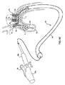
移植片送達および展開システムは、一実施形態では、一連のガイドワイヤ、遠位カテーテル部分、および近位ハンドル部分を含み、植込型デバイスは、標的部位への送達に先立って、カテーテル部分に装填される。システムの少なくともカテーテル部分は、移植のために選択されるそれらそれぞれの標的血管内に、ステントまたはステントグラフトおよびその分岐のそれぞれを誘導および配置する、1つ以上のガイドワイヤ上で追跡される。種々の制御は、移植片の管腔末端の選択的な引張および解放のために提供され、制御は、ハンドル部分、カテーテル部分または両方上に位置する。好適な実施形態においては、カテーテル部分および/または送達ガイドワイヤは、それらの遠位端において連接可能であり、血管系を通したナビゲーションを促進する。 The implant delivery and deployment system, in one embodiment, includes a series of guidewires, a distal catheter portion, and a proximal handle portion, and the implantable device is loaded into the catheter portion prior to delivery to the target site. Is done. At least the catheter portion of the system is tracked on one or more guidewires that guide and place each of the stents or stent grafts and their branches within their respective target vessels selected for implantation. Various controls are provided for selective pulling and release of the luminal end of the graft, the controls being located on the handle portion, the catheter portion or both. In preferred embodiments, the catheter portions and / or delivery guidewires can be articulated at their distal ends to facilitate navigation through the vasculature.
システムの一実施形態は、連接する送達ガイドワイヤまたはガイドカテーテルを含む。連接ガイドワイヤは、1つ以上の連接点を有してもよく、操作者は、ガイドワイヤの近位部分の操作によって、ガイドワイヤの遠位部分の形状を変更できる。ガイドワイヤは、まっすぐな構成から、ガイドワイヤの近位部分の操作中に個々の連接点を制御することによってもたらされる一連の種々の事前選択した形状に変わるように事前構成することができる。このように、ガイドワイヤは、血管系の個別領域にアクセスするための固有の仕様に製造され得る。例えば、これは、空のポイントから移植標的部位への「S」型パスを要する領域内に移植片を配置する際に特に重要となり得る。腕頭動脈内の移植標的に至る大腿動脈アクセスポイントを通したガイドワイヤの導入は、かかる連接ガイドワイヤが有利となり得る、潜在的に困難な「S」型ナビゲーション経路の一例を示す。 One embodiment of the system includes an articulating delivery guidewire or guide catheter. The articulating guidewire may have one or more articulating contacts, and the operator can change the shape of the distal portion of the guidewire by manipulating the proximal portion of the guidewire. The guide wire can be pre-configured to change from a straight configuration to a series of different pre-selected shapes that are provided by controlling individual articulation contacts during manipulation of the proximal portion of the guide wire. In this way, the guidewire can be manufactured to a specific specification for accessing individual areas of the vasculature. For example, this can be particularly important when placing a graft in an area that requires an “S” shaped path from an empty point to the target site for implantation. The introduction of a guidewire through a femoral artery access point to the implantation target in the brachiocephalic artery represents an example of a potentially difficult “S” type navigation path where such articulated guidewire can be advantageous.
本発明の方法は、植込型デバイスを展開するステップを含み、該方法の一部は、対象システムの使用を含む。植込型デバイスを製造するための方法も提供される。 The method of the present invention includes deploying an implantable device, and part of the method includes the use of a target system. A method for manufacturing an implantable device is also provided.
本発明の別の目的は、ステントが配置される血管の一時的な閉塞を生じないステント展開の方法を提供する。 Another object of the present invention is to provide a method of stent deployment that does not cause temporary occlusion of the blood vessel in which the stent is placed.
本発明の別の目的は、単一アクセス位置から血管系に入るガイドワイヤおよび送達システムを使用するステント展開の方法を提供する。 Another object of the present invention provides a method of stent deployment using a guidewire and delivery system that enters the vasculature from a single access location.
本発明のステント送達システムの利点は、空間を占拠するスタイレットおよびバルーンカテーテルの使用を必要としないことである。 An advantage of the stent delivery system of the present invention is that it does not require the use of space occupying stylets and balloon catheters.
対象システムの別の利点は、その展開中および後に、ステントの配置、設置、ならびに除去の調整を可能にすることである。 Another advantage of the subject system is that it allows adjustment of stent placement, placement, and removal during and after its deployment.
本発明は、加えて、ユーザにステントを展開する能力を提供し、放射線不透過性染色および蛍光透視法、または任意の他の撮像システムを使用する等、標準的な撮像を使用して、結果として生じる展開の適切性を評価し、適度なステント展開時、または不適切な展開の場合において、被覆されるステント壁と周囲の動脈壁との間の内部漏出を確認し、送達システムからステントを引き離して、反復可能な方法でステントの送達および引き離しを制御することによって、ステントを新しい位置に再配置して満足な結果を得るか、またはステント全体を除去することにおいて有利である。 The present invention additionally provides the user with the ability to deploy the stent and results using standard imaging, such as using radiopaque staining and fluoroscopy, or any other imaging system. To assess the appropriateness of the resulting deployment, and during internal or improper deployment, check for internal leakage between the coated stent wall and the surrounding arterial wall and remove the stent from the delivery system. By separating and controlling the delivery and withdrawal of the stent in a repeatable manner, it may be advantageous to reposition the stent to a new location to obtain satisfactory results or to remove the entire stent.
本発明は、加えて、側枝管腔のセルを本体管腔のセルに統合することによって、血管系内での移行からステントを固定することにおいて有利であり、側枝管腔がそれらの支流血管内で展開されると、本体管腔が「ロック・アンド・キー」機構によって移行しないようにする。より具体的には、側枝管腔の本体管腔への相互接続は、管腔および本体管腔を同一の単一ワイヤで形成することによって達成され、特定のワイヤラップパターンを使用して、側枝管腔を主要管腔に統合するための連結メッシュを形成する。したがって、側枝が側枝動脈内で展開され、所定の位置に保持されると、ステントの本体は移行できない。さらに、かかる「受動的」固定機構は、非外傷性であり、移植部位の細胞構造を損傷し、平滑筋増殖、再狭窄、および他の血管合併症に至り得る、バーブまたはフック等の能動的固定機能とは対称的である。 The present invention is also advantageous in securing stents from transition within the vasculature by integrating the side branch lumen cells into the body lumen cells, where the side branch lumens are within their tributary vessels. When deployed, the body lumen is prevented from transitioning by a “lock and key” mechanism. More specifically, the interconnection of the side branch lumen to the body lumen is accomplished by forming the lumen and the body lumen with the same single wire, and using a specific wire wrap pattern, A connecting mesh is formed to integrate the lumens into the main lumen. Thus, once the side branch is deployed in the side branch artery and held in place, the stent body cannot migrate. In addition, such “passive” anchoring mechanisms are active such as barbs or hooks that are atraumatic and can damage the cellular structure at the site of implantation, leading to smooth muscle proliferation, restenosis, and other vascular complications. The fixed function is symmetrical.
本発明のこれらおよび他の目的、利点、および機能は、以下により完全に記載されるように、本発明の詳細を読むことで当業者に明らかとなる。 These and other objects, advantages and features of the present invention will become apparent to those of ordinary skill in the art upon reading the details of the invention as described more fully below.
本発明は、付随の図面と併せて読むと、以下の発明を実施するための形態からもっともよく理解される。一般的な実践に従って、図面の種々の特徴は、縮尺どおりでないことが強調される。反対に、種々の特徴の寸法は、明確にするために、任意に拡大または縮小される。また明確にする目的で、本発明のある特徴は、図面の一部に描写されない場合がある。図面には以下の図が含まれる。
本発明のデバイス、システムおよび方法を説明する前に、本発明は、説明される特定の治療への応用および移植部位に限定されず、そのようなものとして、異なり得ることを理解されたい。本発明の範囲は、添付の請求項によってのみ限定されるため、本明細書で使用される用語は、特定の実施形態のみを説明する目的のためであって、限定することを意図しないことも理解されたい。 Before describing the devices, systems and methods of the present invention, it is to be understood that the present invention is not limited to the particular therapeutic application and implantation site described, and as such may vary. Since the scope of the present invention is limited only by the appended claims, the terminology used herein is for the purpose of describing particular embodiments only and is not intended to be limiting. I want to be understood.
別段の定義がない限り、本明細書で使用されるすべての技術的および科学的用語は、本発明が属する技術において当業者に一般に理解されるものと同一の意味を有する。「近位」および「遠位」という用語が使用される場合、ユーザに関連する位置または場所を示すために理解されるべき本発明の送達および展開システムを意味し、ここで近位はユーザにより近い位置または場所を意味し、遠位はユーザから遠く離れた位置または場所を意味する。本発明の植込型デバイスを参照して使用される場合、これらの用語は、植込型デバイスがシステム内に動作可能に配置される場合に、送達および展開システムに関連する位置または場所を示すと理解される。そのようにして、近位は送達および展開システムにより近い位置または場所を意味し、遠位は送達および展開システムの遠位端により近い位置または場所を意味する。本明細書で使用される「移植片」または「植込型デバイス」という用語は、ステント、グラフト、ステントグラフト等を備えるデバイスを含むが、それに限定されない。 Unless defined otherwise, all technical and scientific terms used herein have the same meaning as commonly understood by one of ordinary skill in the art to which this invention belongs. When the terms “proximal” and “distal” are used, it means the delivery and deployment system of the present invention to be understood to indicate the location or location associated with the user, where proximal is defined by the user A near position or location is meant, and distal means a location or place far away from the user. When used in reference to the implantable device of the present invention, these terms indicate the location or location associated with the delivery and deployment system when the implantable device is operably disposed within the system. It is understood. As such, proximal means a position or location that is closer to the delivery and deployment system, and distal means a position or location that is closer to the distal end of the delivery and deployment system. The term “implant” or “implantable device” as used herein includes, but is not limited to, devices comprising stents, grafts, stent-grafts and the like.
ここで、本発明のデバイス、システム、および方法の例示的実施形態および変形例に関する以下の説明によって、本発明についてさらに詳細に説明する。本発明は、概して、ステント、グラフト、またはステントグラフトの形態の管状部材を含む植込型デバイスを含み、デバイスは、主要または一次管状部材から側方に延在する1つ以上の分岐または横管状部材をさらに含み得る。本発明は、体内の標的移植部位おける植込型デバイスの経皮、血管内送達および展開のためのシステムをさらに含む。移植部位は、任意の管状または中空組織管腔あるいは器官であり得るが、しかしながら、大部分の典型的な移植部位は、血管構造、特に大動脈である。本発明の特徴は、それが、2つ以上の交差する管状構造を含む適用に対応し、そのようにして、特に、大動脈弓および腎臓下大動脈等の血管系を治療する局面において適していることである。 The present invention will now be described in further detail by the following description of exemplary embodiments and variations of the devices, systems, and methods of the present invention. The present invention generally includes an implantable device that includes a tubular member in the form of a stent, graft, or stent-graft, the device including one or more bifurcated or transverse tubular members that extend laterally from the primary or primary tubular member. May further be included. The present invention further includes a system for transdermal, intravascular delivery and deployment of an implantable device at a target implantation site in the body. The implantation site can be any tubular or hollow tissue lumen or organ, however, most typical implantation sites are vascular structures, particularly the aorta. A feature of the present invention is that it accommodates applications involving two or more intersecting tubular structures, and is thus particularly suitable in the aspect of treating vascular systems such as the aortic arch and the subrenal aorta. It is.
(本発明の植込型デバイス)
ここで図、特に図1Aおよび1Bを参照して、本発明の植込型デバイスの例示的実施形態について説明する。デバイスのそれぞれは、一次または主要管状部材、および少なくとも1つの側方に延在する管状分岐を有するが、しかしながら、本発明の植込型デバイスは、側枝を有する必要はない。
(Implantable device of the present invention)
With reference now to the figures and in particular with reference to FIGS. 1A and 1B, exemplary embodiments of the implantable device of the present invention will be described. Each of the devices has a primary or primary tubular member and at least one laterally extending tubular branch, however, the implantable devices of the present invention need not have side branches.
図1Aは、一次管状部分、本体または部材4、および体内の側面開口によって本体4と相互接続され、流体連通する、側方に延在する側枝6a、6b、および6cを有する植込型デバイス2の一変形例を説明する。主要管状部材4の近位および遠位端は、頭頂部または先端8で終結し、その数は異なり得る。側枝6a、6b、および6cの遠位端は、頭頂部または先端10a、10b、および10cでそれぞれ終結し、その数も異なり得る。デバイス2は、特に大動脈弓における移植用に構成され、一次管状部材4は、弓壁内に配置可能で、管状枝6a、6b、および6cは、腕頭動脈、左総頚動脈、および左鎖骨下動脈内にそれぞれ配置可能である。
FIG. 1A shows an implantable device 2 having laterally extending
以下でさらに詳細に記述されるように、対象送達および展開システムの展開または取付部材は、10a、10b、および10cを通して、またはデバイス2の尖端の遠位端から延在する小穴(図示せず)を通してループにする。本発明の取付部材は、任意の細長い部材であってもよく、ストリング、フィラメント、ファイバー、ワイヤ、ねじれケーブル、チューブ、またはステントの種々の管腔の遠位端に解除可能に取付可能な他の細長い部材を含むが、それらに限定されない。解放可能な取付手段は、電解浸食、熱エネルギー、磁気的手段、化学的手段、機械的手段、または任意の他の制御可能な分離手段を含むが、それらに限定されない。 As described in further detail below, the deployment or attachment member of the targeted delivery and deployment system is a small hole (not shown) that extends through 10a, 10b, and 10c or from the distal end of the tip of device 2. Loop through. The attachment member of the present invention may be any elongated member, such as a string, filament, fiber, wire, twisted cable, tube, or other releasably attachable to the distal ends of various lumens of the stent. Including but not limited to an elongated member. Releasable attachment means include, but are not limited to, electrolytic erosion, thermal energy, magnetic means, chemical means, mechanical means, or any other controllable separation means.
図1Bは、一次管状部分、または部材14、および体内の側面開口によって本体14と相互接続され流体連通する、側方に延在する側枝16a、16b、および16cを有するデバイス12の別の変形例を説明する。主要管状部材14の近位および遠位端は、頭頂部または先端18で終結し、図1に関して前述のように採用され、一方、側枝16aおよび16bの遠位端は、頭頂部または先端18aおよび18bでそれぞれ終結する。デバイス12は、特に腎臓下大動脈における移植用に構成され、一次管状部材14は、大動脈壁内に配置可能で、管状枝16aおよび16bは、右および左腎臓動脈内にそれぞれ配置される。
FIG. 1B shows another variation of the
当業者は、対象移植片が任意の数および構成の管腔(例えば、側枝管腔のない単一の主要管腔、主要管腔と1つ以上の側枝管腔)を有し得ることを理解し、ここで、1つ以上の側枝管腔は、主要管腔の長さに沿って任意の適切な場所に、主要管腔の縦軸に対して任意の角度で配置され得、2つ以上の側枝管腔が存在する場合は、管腔は互いに対して軸方向に間隔があけられ、および円周方向に角度を付けられて、移植片が配置される標的血管系を適応させ得る。加えて、移植片の管腔の長さ、直径、および形状(例えば、曲率半径)は、必要に応じて異なり得、それが配置される血管に対応する。ある適用においては、特に、主要血管と支流血管との間の接合点付近に位置する比較的に大きい頚部分を有する血管動脈瘤を治療する場合、側枝管腔が平均よりも比較的に長い場合は、分岐ステントを提供することが好ましい場合がある。より長いステント分岐は、それらの遠位端において十分な長さを維持しながら、頚部開口を架橋して、ステントを係止するために十分な血管側枝への距離を延長することができる。 One skilled in the art understands that a subject graft can have any number and configuration of lumens (eg, a single main lumen without side branch lumens, a main lumen and one or more side branch lumens). Where one or more side branch lumens may be disposed at any suitable location along the length of the main lumen at any angle relative to the longitudinal axis of the main lumen. If present, the lumens may be axially spaced relative to each other and angled circumferentially to accommodate the target vasculature in which the implant is placed. In addition, the length, diameter, and shape (eg, radius of curvature) of the graft lumen can vary as needed, corresponding to the vessel in which it is placed. In certain applications, especially when treating vascular aneurysms with a relatively large neck located near the junction between the main and tributary vessels, the side branch lumen is relatively longer than average It may be preferable to provide a bifurcated stent. Longer stent branches can bridge the cervical opening and extend the distance to the side vessel branch sufficient to lock the stent while maintaining sufficient length at their distal ends.
典型的には、大部分の血管のための対象デバイスは、約1cm〜約25cmの範囲内の限定されない長さ、および約2mm〜約42mmの範囲内の限定されない直径を有する主要枝管腔と、約0.5cm〜約8cmの範囲内の限定されない長さ、および約2mm〜約14mmの範囲内の限定されない直径を有する側枝管腔を有する。大動脈適用の場合は、主要管腔の限定されない長さは、典型的には、約8cm〜約25cmの範囲内であり、限定されない直径は約15mm〜約42mmの範囲内であって、側枝管腔は約2cm〜約8cmの範囲内の限定されない長さ、および約5mm〜約14mmの範囲内の限定されない直径を有する。寸法がステントの主要管腔の直径である場合、縮小直径は、非縮小直径の10分の1に比較的近い可能性が高い。腎臓適用の場合は、主要枝管腔は約2cm〜約20cmの範囲内の限定されない長さ、および約12mm〜約25mmの範囲内の限定されない直径を有し、側枝管腔は約0.5cm〜約5cmの範囲内の限定されない長さ、および約4mm〜約12mmの範囲内の限定されない直径を有する。冠動脈適用の場合は、主要枝管腔は約1cm〜約3cmの範囲内の限定されない長さ、および約2mm〜約5mmの範囲内の限定されない直径を有し、側枝管腔は約0.5cm〜約3cmの範囲内の限定されない長さ、および約2mm〜約5mmの範囲内の限定されない直径を有する。神経血管系等のより小さい血管における適用の場合は、これらの寸法は当然ながらより小さくなる。ある適用において、特に主要血管と支流血管との間の接合点付近に位置する比較的に大きい頸部分を有する血管動脈瘤を治療する場合、分岐ステントを提供することが好ましい場合があり、側枝管腔は、比較的に平均よりも長い。より長いステント枝は、頸部の開口を架橋する一方で、それらの遠位端に十分な長さを維持し、ステントを固定するための十分な血管側枝への距離を延長することができる。 Typically, a subject device for most blood vessels has a main branch lumen having an unrestricted length in the range of about 1 cm to about 25 cm and an unrestricted diameter in the range of about 2 mm to about 42 mm. A side branch lumen having a non-limiting length in the range of about 0.5 cm to about 8 cm, and a non-limiting diameter in the range of about 2 mm to about 14 mm. For aortic applications, the unrestricted length of the main lumen is typically in the range of about 8 cm to about 25 cm, and the non-limiting diameter is in the range of about 15 mm to about 42 mm, and the side branch canal The cavity has an unrestricted length in the range of about 2 cm to about 8 cm, and an unrestricted diameter in the range of about 5 mm to about 14 mm. If the dimension is the diameter of the main lumen of the stent, the reduced diameter is likely to be relatively close to 1/10 of the unreduced diameter. For renal application, the main branch lumen has an unrestricted length in the range of about 2 cm to about 20 cm, and an unrestricted diameter in the range of about 12 mm to about 25 mm, and the side branch lumen is about 0.5 cm. Having an unrestricted length in the range of about 5 cm and an unrestricted diameter in the range of about 4 mm to about 12 mm. For coronary applications, the main branch lumen has an unrestricted length in the range of about 1 cm to about 3 cm, and an unrestricted diameter in the range of about 2 mm to about 5 mm, and the side branch lumen is about 0.5 cm Having an unrestricted length in the range of about 3 cm and an unrestricted diameter in the range of about 2 mm to about 5 mm. For applications in smaller blood vessels such as the neurovascular system, these dimensions are naturally smaller. In certain applications, it may be preferable to provide a bifurcated stent, especially when treating a vascular aneurysm having a relatively large neck portion located near the junction between the main vessel and the tributary vessel, and the side branch vessel The cavity is relatively longer than average. Longer stent branches can bridge the neck openings while maintaining sufficient length at their distal ends to extend the distance to sufficient vessel side branches to secure the stent.
治療または診断組成物またはデバイスが対象移植片と一体化され得ることも考慮される。かかるデバイスは、心臓弁(例えば、大動脈または肺弁)および静脈弁等の人工弁、血流、圧力、酸素濃度、グルコース濃度等を測定するためのセンサ、電気ペーシングリード等を含むが、それらに限定されない。例えば、図1Eで説明されるように、大動脈起始部を治療するための移植片210が提供され、主要管腔212の遠位端で採用される機械的または生物学的人工弁216を含む。デバイス210は、それぞれ右および左冠状動脈口内に配置するために調節可能に整列した、2つのより小さい、概して対向する側枝管腔214aおよび214bをさらに含む。大動脈弓の前、内部、または後の任意の位置で終結する場合に選択した距離まで伸長、例えば、下行大動脈に伸長するように、ステントグラフトの長さが選択される。大動脈弓支流血管を適応させるために、任意の数の追加の側枝を提供してもよい。
It is also contemplated that a therapeutic or diagnostic composition or device can be integrated with the subject implant. Such devices include heart valves (eg, aortic or pulmonary valves) and artificial valves such as venous valves, sensors for measuring blood flow, pressure, oxygen concentration, glucose concentration, electrical pacing leads, etc. It is not limited. For example, as illustrated in FIG. 1E, an
当業者は、任意の適切なステントまたはグラフト構成を提供して、大動脈−腸骨接合、大腿骨−膝窩接合、短頭動脈、後部脊椎動脈、冠状動脈分岐、頚動脈、上下腸間膜動脈、一般胃腸動脈、頭蓋動脈、および神経血管分岐を含むが、それらに限定されない、2つ以上の血管(例えば、分岐、三叉、四裂等)、交差点またはその付近の他の血管位置における他の適用を治療し得ることを認識するであろう。 Those skilled in the art will provide any suitable stent or graft configuration to provide aortic-iliac joint, femoral-popliteal joint, short head artery, posterior vertebral artery, coronary artery bifurcation, carotid artery, superior and inferior mesenteric artery, Other applications at two or more blood vessels (eg, bifurcation, trigeminal, quadrilateral, etc.), intersections or other vascular locations near, including, but not limited to, general gastrointestinal arteries, cranial arteries, and neurovascular bifurcations Will recognize that it can be treated.
本発明のステントおよびグラフトは、当該技術において知られる任意の適切な材料で形成され得る。好ましくは、ステントはワイヤで構成されるが、任意の適切な材料で代用されてもよい。ワイヤステントは、弾性的に柔軟である必要があり、例えば、ステントは、ステンレス鋼、エルジロイ、タングステン、プラチナ、またはニチノールで形成され得るが、任意の他の適切な材料をこれらの一般的に使用される材料の代わりに、または加えて使用してもよい。 The stents and grafts of the present invention can be formed of any suitable material known in the art. Preferably, the stent is comprised of a wire, but any suitable material may be substituted. Wire stents need to be elastically flexible, for example, the stent can be formed of stainless steel, elgiloy, tungsten, platinum, or nitinol, but any other suitable material is commonly used for these It may be used instead of or in addition to the material to be made.
ステントは、任意の適切なワイヤにパターを形成させるか、またはチューブまたは平面シートから切り出されてもよい。一実施形態では、全体ステント構造は、単一ワイヤ織布から、例えば閉じた鎖状リンク構成を形成する相互接続セルのパターンに加工される。構造は、まっすぐな円筒形構成、湾曲管状構成、テーパ中空構成を有し、非対称のセルサイズを有してもよく、例えば、セルサイズは、ステントの長さに沿ってまたは外周で異なり得る。あるステント実施形態においては、側枝管腔のセルサイズは、遠位方向に徐々に減少する。これは、側枝管腔の最遠部分を選択的に伸張する能力をさらに促進し、したがって、医師が側枝の遠位端を指定血管にガイドすることを容易にする。主要ステント管腔の末端および/または1つ以上の側枝ステント管腔の末端はフレアであり得る。ステントのストラット(すなわち、セルを形成する基礎部分)は、直径(ワイヤ実施形態における)または厚さあるいは幅(シートおよびカットチューブ実施形態における)が異なり得る。 The stent may be puttered on any suitable wire or cut from a tube or flat sheet. In one embodiment, the entire stent structure is fabricated from a single wire woven fabric into a pattern of interconnected cells that form, for example, a closed chain link configuration. The structure may have a straight cylindrical configuration, a curved tubular configuration, a tapered hollow configuration, and may have an asymmetric cell size, for example, the cell size may vary along the length of the stent or at the outer periphery. In certain stent embodiments, the side branch lumen cell size gradually decreases in the distal direction. This further facilitates the ability to selectively stretch the farthest portion of the side branch lumen, thus facilitating the physician to guide the distal end of the side branch to the designated vessel. The end of the main stent lumen and / or the end of one or more side branch stent lumens may be flared. The struts of the stent (ie, the base portion forming the cell) can vary in diameter (in the wire embodiment) or thickness or width (in the sheet and cut tube embodiments).
特定の一実施形態においては、ステントは、単一ワイヤから構成される。単一ワイヤステント構成は、ステントの長さに沿う接続ポイントの選択的な飛び越しを介して、治療対象の生体構造における任意の可能な変形に対応し得る選択範囲内で、互いに関する、および主要ステント管腔に関する側枝ステントの角度配向における適応性を提供することにおいて有利である。かかる側枝管腔の角度配向は、軸方向、半径方向、または両方であり得る。 In one particular embodiment, the stent is composed of a single wire. The single wire stent configuration relates to each other and the main stent within a selection range that can accommodate any possible deformation in the anatomy to be treated, through selective jumping of connection points along the length of the stent. It is advantageous in providing flexibility in the angular orientation of the side branch stent with respect to the lumen. The angular orientation of such side branch lumens can be axial, radial, or both.
図1Cは、側枝管腔24および26がそれぞれ、主要管腔22に対して角度αによって画定される角度配向を有し、互いに対して角度βによって画定される角度配向を有する移植デバイス20を示す。図1Dは、側枝管腔22と24との間の角度θによって画定される円周配向を示す移植デバイス20である。種々の角度の典型的な範囲は、角度αの場合は約10°〜約170°、角度βの場合は約0°〜約170°、角度θの場合は0°〜360°である。これらの配向は、必然的に限定されない事前展開された状態、すなわち、中立状態において偏向配向を有するステントを生じる加工プロセスによって提供され得る。これらの配向のうちの1つ以上を、それぞれの血管管腔内での分岐管腔の送達および配置時に、上で提供される角度範囲内で選択的に調整してもよい。この設計もまた、ステントの主要管腔を伸張および/または短縮することによって、側枝ステント間の線形間隙の適応性を可能にする。さらに、側枝部分は、引き伸ばされることにより、大型ステントをより小さい支流
血管に配置することができ、それによって、ステントと血管壁との間に適度な接合を提供する。ステントの適応性は、固定または係止に必要な半径方向力を低下させず、デバイスの移動および内部漏出を回避する。
FIG. 1C shows an
対象デバイスは、それらの管腔が、それらの長さおよび周長に沿って一定また
は可変の剛性/可撓性を有し得るように加工することもできる。より優れた可撓性によって、送達中および移植部位において遭遇する曲線血管系に、より良好に適応できる。かかる特徴は、大動脈弓の比較的「タイトな」湾曲に対して、大動脈弓ステント留置適用において極めて有利である。一方、特に管腔の末端部分において強化された剛性は、より大きな半径方向力を付与し、それによって配置後の血管系内におけるデバイスの移動に耐える。可変の可撓性/剛性は、種々の方法で実装され得る。
The subject devices can also be machined so that their lumens can have a constant or variable stiffness / flexibility along their length and circumference. Better flexibility allows better adaptation to the curved vasculature encountered during delivery and at the site of implantation. Such a feature is extremely advantageous in aortic arch stenting applications relative to the relatively “tight” curvature of the aortic arch. On the other hand, enhanced stiffness, particularly in the distal portion of the lumen, provides greater radial force, thereby resisting device movement within the vasculature after placement. Variable flexibility / stiffness may be implemented in various ways.
デバイスの加工に使用される1つまたは複数のストラット(すなわち、ステントセルを形成する基礎部分)のゲージまたは厚さは変化し得、より厚いゲージがより高い剛性を付与し、より薄いゲージがより高い可撓性を付与する。ステントのストラットは、直径(ワイヤ実施形態において)または厚さあるいは幅(シートおよびカットチューブ実施形態において)が変化し得る。一変形例においては、ゲージがその長さに沿って選択的に変化する場合は、単一ワイヤまたはフィラメントを使用してもよい。より厚いゲージ部分を使用して、少なくともステント管腔の末端部分を形成し、それらの半径方向力を増加させ、それによって、ステントの移動リスクを減少させる。反対に、ワイヤのより狭いゲージ部分は、主要ステント管腔の少なくとも中心部分(および側枝管腔の一部)を形成し、末端部分よりも比較的に可撓性が高く、蛇行性または湾曲する血管系内のステントの送達を容易にするか、またはデバイスをより容易に圧縮して送達シースに入れることができる。大動脈ステント適用の場合は、このことは、残りの中心部分よりも大きい直径を有するその末端のそれぞれに、1〜2cmの部分を有するワイヤによって達成され得る。ワイヤの断面直径を選択的に減少させる別の実施例は、側枝ステントのストラットの直径をより小さくすることである。 The gauge or thickness of one or more struts used to fabricate the device (ie, the base portion forming the stent cell) can vary, with thicker gauges providing higher stiffness and thinner gauges being more Gives high flexibility. Stent struts can vary in diameter (in wire embodiments) or thickness or width (in sheet and cut tube embodiments). In one variation, a single wire or filament may be used if the gauge selectively changes along its length. A thicker gauge portion is used to form at least the distal portion of the stent lumen and increase their radial force, thereby reducing the risk of stent migration. Conversely, the narrower gauge portion of the wire forms at least the central portion (and part of the side branch lumen) of the main stent lumen and is relatively more flexible and serpentine or curved than the distal portion. The delivery of the stent within the vasculature can be facilitated, or the device can be more easily compressed into the delivery sheath. For aortic stent applications, this can be achieved by a wire having a 1-2 cm portion at each of its ends having a larger diameter than the remaining central portion. Another example of selectively reducing the cross-sectional diameter of the wire is to reduce the diameter of the side branch stent struts.
他の実施形態では、2つ以上のワイヤが使用され、ワイヤはそれぞれ、各長さに沿って一定のゲージを有するが、ワイヤごとに異なる。高い剛性が必要な場合は、より大きいゲージのワイヤを使用して、ステント末端または他の領域を形成してもよく、一方で高い可撓性が必要な場合は、より狭いゲージのワイヤを使用して、他の部分、例えば、ステント管腔の中心部分を形成してもよい。加えて、または代替として、ステントの周辺の選択ポイントまたは場所において、より大きいゲージのワイヤを選択的に二つ折りにするか、またはより狭いゲージのワイヤによって巻かれることにより、それらの特定部位における剛性を増強することができる。 In other embodiments, two or more wires are used, each wire having a constant gauge along each length, but different for each wire. If higher stiffness is required, a larger gauge wire may be used to form the stent end or other area, while a narrower gauge wire is used if higher flexibility is required. Thus, other portions may be formed, for example, the central portion of the stent lumen. In addition, or alternatively, stiffness at those specific locations by selectively folding the larger gauge wire in half or winding it with a narrower gauge wire at selected points or locations around the stent Can be strengthened.
一変形例においては、2つ以上のワイヤを採用して、デバイスを形成することができ、それによってワイヤ末端、すなわち、2つのワイヤから形成されたデバイスの場合は4つのワイヤ末端が結合される。ワイヤが互いに交差する、および/またはそれらの末端が結合する管腔を中心とした位置を選択して、管腔に沿うか、またはその周囲のある領域において剛性を最小にし、および/またはデバイスの1つ以上の他の領域において剛性を強化し、すなわち、ステントの部分の間に相対的な剛性および可撓性を提供する。例えば、大動脈弓適用において、下壁はよりタイトな曲率半径を有するため、弓の下壁に沿って整列させることが意図されるステントの主要管腔の部分は、弓の上壁に沿って整列させることが意図されるステントの部分より優先的に可撓性が比較的に高く、および/または剛性が低い。したがって、ステントのこの部分に沿うワイヤの接合および/または交差点を最小化することが望ましい場合がある。 In one variation, two or more wires can be employed to form the device, thereby joining the wire ends, ie, in the case of a device formed from two wires, four wire ends. . Select a location centered on the lumen where the wires intersect each other and / or their ends join to minimize stiffness in a region along or around the lumen and / or the device It enhances stiffness in one or more other regions, i.e., provides relative stiffness and flexibility between portions of the stent. For example, in an aortic arch application, because the lower wall has a tighter radius of curvature, the portion of the main lumen of the stent that is intended to be aligned along the lower wall of the arch aligns along the upper wall of the arch It is preferentially more flexible and / or less rigid than the portion of the stent intended to be made. Thus, it may be desirable to minimize wire bonding and / or intersections along this portion of the stent.
主要管腔と側枝管腔との間の接合点において、より高い剛性を提供することが望ましい場合もある。大動脈瘤、および特に大動脈弓と1つ以上のその支流血管との交差点に位置する動脈瘤は、血管系内に比較的大量の明確に画定されていないペリメータ、すなわち、「サック(袋)」をもたらし得る。それ自体を強化する血管壁がない場合、ステント接合点はよりねじれ易くなり得る。ステントの接合点を補強することによって、かかるねじれを回避できる。 It may be desirable to provide greater rigidity at the junction between the main lumen and the side branch lumen. An aneurysm, and particularly an aneurysm located at the intersection of an aortic arch and one or more of its tributary vessels, has a relatively large number of well-defined perimeters, or “sacks”, in the vasculature. Can bring. In the absence of a vessel wall that reinforces itself, the stent junction can be more likely to twist. By reinforcing the junction of the stent, such twisting can be avoided.
同時係属中の2006年10月6日出願の米国特許出願第11/539,478号およびこれと同時に出願された別の米国特許出願(代理人整理番号DUKEPZ01101を有する)は、いずれも血管移植片および同一を加工する方法という名称であり、参照することによって本明細書に組み込まれ、上述の剛性および可撓性特性を選択的に強化するための多くの特徴を有するステントデバイスを開示している。 No. 11 / 539,478, filed Oct. 6, 2006, and copending US patent application filed at the same time (with agent docket number DUKEPZ01101) are both vascular grafts. And a method of processing the same, which is incorporated herein by reference and discloses a stent device having many features for selectively enhancing the above-described stiffness and flexibility properties. .
前述のように、本発明の植込型デバイスは、ステントグラフト、またはステントされたグラフト、あるいはグラフト付きステントと称される2つの組み合わせを含み得る。ステントグラフトのグラフト部分は、織物、ポリマー、ラテックス、シリコンラテックス、ポリエトラフルオロエチレン、ポリエチレン、ダクロンポリエステル、ポリウレタンシリコン、ポリウレタンコポリマー、または生体組織等の他の適切な材料から形成され得る。グラフト材料は、設置および利用の影響に耐えるために、可撓性で耐久性がある必要がある。当業者は、対象発明のグラフトが、多くの異なるよく知られた方法、例えば、織ることによって調製されるか、または基板を所望の材料に浸すことによって形成され得ることを認識するであろう。例示的なグラフト加工方法は、上で参照される同時出願の米国特許出願において開示される。 As mentioned above, the implantable device of the present invention may comprise a combination of the two referred to as a stent graft, or a stented graft, or a grafted stent. The graft portion of the stent graft can be formed from a fabric, polymer, latex, silicone latex, polytetrafluoroethylene, polyethylene, dacron polyester, polyurethane silicone, polyurethane copolymer, or other suitable material such as biological tissue. The graft material needs to be flexible and durable to withstand the effects of installation and use. One skilled in the art will recognize that the grafts of the subject invention can be prepared by many different well known methods, for example, by weaving or by immersing the substrate in the desired material. Exemplary graft processing methods are disclosed in the co-pending US patent application referenced above.
グラフト材料(およびステント)を形成するために使用され得る生体組織は、細胞外マトリクス(ECM)、無細胞化子宮壁、脱細胞化窩洞層または膜、無細胞尿管膜、臍帯組織、脱細胞化心膜およびコラーゲンを含むが、それらに限定されない。適切なECM材料は、哺乳類宿主源に由来し、小腸粘膜下組織、肝臓基底膜、膀胱粘膜下組織、胃粘膜下組織、真皮等を含むが、それらに限定されない。本発明との使用に適切な細胞外マトリクスは、哺乳類小腸粘膜下組織(SIS)、胃粘膜下組織、膀胱粘膜下組織(UBS)、真皮、またはヒツジ、ウシ、ブタ、または任意の適切な哺乳類に由来する肝臓基底膜を含む。 Biological tissues that can be used to form the graft material (and stent) include extracellular matrix (ECM), acellularized uterine wall, decellularized cavity layer or membrane, acellular ureteral membrane, umbilical cord tissue, decellularized Including but not limited to pericardium and collagen. Suitable ECM materials are derived from mammalian host sources and include, but are not limited to, small intestine submucosa, liver basement membrane, bladder submucosa, gastric submucosa, dermis and the like. Suitable extracellular matrices for use with the present invention include mammalian small intestine submucosa (SIS), gastric submucosa, bladder submucosa (UBS), dermis, or sheep, cow, pig, or any suitable mammal A liver basement membrane derived from
温血脊椎動物の粘膜下組織(ECM)は、組織グラフト材料において有用である。小腸に由来する粘膜下組織グラフト組成物は、米国特許第4,902,508号(以下’508号特許と称する)および米国特許第4,956,178号(以下’178号特許と称する)において説明されており、膀胱に由来する粘膜下組織グラフト組成物は、米国特許第5,554,389号(以下’389号特許と称する)において説明されている。これらの(ECM)組成物のすべては、概して、同一組織層で構成され、同一方法で調製されるが、一方は出発材料が小腸であり、他方は膀胱であることが異なる。’508号特許において詳述される手順は、参照することによって’389号特許に組み込まれ、’178号特許に詳述される手順は、機械的磨耗ステップを含み、少なくとも小腸または膀胱の粘膜の管腔部分、すなわち、’178号特許に詳述されるように、上皮板粘膜(上皮)および固有層を含む、組織の内側層を除去する。粘膜を磨耗、剥離、または切削することで、上皮細胞およびそれらの関連基底膜、および固有層の大部分、少なくとも系統的な密集した結合組織層レベルまで薄い層に裂く。したがって、組織グラフト材料(ECM)、上皮基底膜を含まず、粘膜下組織および細胞層で構成される軟組織置換材料として既に認識されている。 Warm-blooded vertebrate submucosa (ECM) is useful in tissue graft materials. Submucosal tissue graft compositions derived from the small intestine are described in US Pat. No. 4,902,508 (hereinafter referred to as the '508 patent) and US Pat. No. 4,956,178 (hereinafter referred to as the' 178 patent). Described, submucosal tissue graft compositions derived from the bladder are described in US Pat. No. 5,554,389 (hereinafter referred to as the '389 patent). All of these (ECM) compositions are generally composed of the same tissue layer and prepared in the same manner, except that one is the small intestine and the other is the bladder. The procedure detailed in the '508 patent is incorporated by reference into the' 389 patent, and the procedure detailed in the '178 patent includes a mechanical wear step, at least in the mucosa of the small intestine or bladder. The luminal portion, ie, the inner layer of tissue, including the epithelial mucosa (epithelium) and the lamina propria, is removed as detailed in the '178 patent. Abrasion, detachment, or cutting of the mucous membranes tears the epithelial cells and their associated basement membrane, and the majority of the lamina propria into a thin layer, at least to a systematic and dense connective tissue layer level. Therefore, it is already recognized as a soft tissue replacement material that does not include tissue graft material (ECM) and epithelial basement membrane and is composed of submucosa and cell layers.
基底膜を有する典型的な上皮の実施例は、皮膚の上皮、腸、膀胱、食道、胃、角膜、および肝臓を含むが、それらに限定されない。上皮基底膜は、上皮細胞の基底側面と隣接する細胞外材料の薄いシートの形態で形成され得る。同様の種類の凝集した上皮細胞のシートは、上皮を形成する。上皮細胞およびそれらの関連上皮基底膜葉、粘膜の管腔部分上に配置することができ、体内の管状および中空器官および組織の内部表面で構成される。結合組織および粘膜下組織は、例えば、基底膜の腹部または深部側に配置される。上皮基底膜の腹部側に配置されるECMの形成に使用される結合組織の実施例は、腸および膀胱(UBS)の粘膜下組織、および皮膚の真皮および皮下組織を含む。粘膜下組織は、約80ミクロメータの厚さを有し、主に(98%以上)細胞、好酸性染色(H&E染色)細胞外マトリクス材料で構成される。繊維芽細胞と一致する偶発的血管およびスピンドル細胞は、組織全体にランダムに散在し得る。典型的には、材料を生理食塩水で洗浄し、使用するまで凍結水和状態で選択的に保存する。 Exemplary epithelial examples having a basement membrane include, but are not limited to, the epithelium of the skin, intestine, bladder, esophagus, stomach, cornea, and liver. The epithelial basement membrane can be formed in the form of a thin sheet of extracellular material adjacent to the basal side of the epithelial cells. Similar types of aggregated epithelial cell sheets form the epithelium. Epithelial cells and their associated epithelial basement membrane lobes can be placed on the luminal portion of the mucosa and are composed of tubular and hollow organs and internal surfaces of tissues in the body. The connective tissue and the submucosa are arranged, for example, on the abdomen or deep side of the basement membrane. Examples of connective tissue used to form ECMs placed on the abdominal side of the epithelial basement membrane include the submucosa of the intestine and bladder (UBS), and the dermis and subcutaneous tissue of the skin. The submucosa has a thickness of about 80 micrometers, and is composed mainly of (98% or more) cells, an acidophilic staining (H & E staining) extracellular matrix material. Incidental blood vessels and spindle cells consistent with fibroblasts can be randomly scattered throughout the tissue. Typically, the material is washed with saline and selectively stored in a frozen hydrated state until use.
流動化UBS、 例えば、米国特許第5,275,826号に記載されるように、流動化腸粘膜下組織の調製と同様の方法で調製することができ、その開示は、参照することによって明示的に本明細書に組み込まれる。UBSは、治療、切断、研削、剪断等によって細分される。凍結または凍結乾燥状態でのUBSの研削が好適であるが、良好な結果は、粘膜下組織片の懸濁液を高速(高い剪断)ブレンダーで処理して水を取り除き、必要であれば、遠心分離して過剰な水分を静注することによって、同様に得ることができる。加えて、細分された流動化組織は、トリプシンまたはペプシン等のプロテアーゼを用いた膀胱粘膜下細胞の酵素消化、または該組織を溶解して、実質的に均一な溶液を形成するために十分な期間、他の適切な酵素によって可溶化することができる。 Fluidized UBS can be prepared in a manner similar to that of fluidized intestinal submucosa, for example as described in US Pat. No. 5,275,826, the disclosure of which is expressly incorporated by reference. Specifically incorporated herein. UBS is subdivided by treatment, cutting, grinding, shearing, and the like. Grinding UBS in the frozen or lyophilized state is preferred, but good results are obtained by treating the suspension of submucosa with a high speed (high shear) blender to remove the water and, if necessary, centrifugation. It can be similarly obtained by separating and intravenously injecting excess water. In addition, the subdivided fluidized tissue is subjected to enzymatic digestion of bladder submucosal cells with a protease such as trypsin or pepsin, or for a period of time sufficient to lyse the tissue and form a substantially homogeneous solution. Can be solubilized by other suitable enzymes.
ステントの被覆は、粉末形態のUBSであり得る。一実施形態では、粉末形態のUBSは、液体窒素下において膀胱粘膜下組織を粉砕して、0.1〜1mm2のサイズの粒子を産生することにより調製される。次いで、粒子の組成物を一晩凍結乾燥および滅菌して、固体の実質的に無水の粒子組成物を形成する。代替として、粉末形態のUBSは、懸濁液または細分されたUBSの溶液を乾燥させることによって、流体化されたUBSから形成されることができる。 The stent coating can be UBS in powder form. In one embodiment, UBS in powder form, by grinding bladder submucosa under liquid nitrogen, are prepared by producing particles of size 0.1 to 1 mm 2. The particle composition is then lyophilized and sterilized overnight to form a solid, substantially anhydrous particle composition. Alternatively, UBS in powder form can be formed from fluidized UBS by drying a suspension or a solution of subdivided UBS.
本発明との使用に適したECM材料の他の実施例は、フィブロネクチン、フィブリン、フィブリノゲン、線維性および非線維性のコラーゲンを含むコラーゲン、粘着性糖タンパク、プロテオグリカン、ヒアルロナン、分泌タンパク酸性高システイン(SPARC)、トロンボスポンジン、テナシン、および細胞粘着性分子、およびマトリクス金属プロテイナーゼ阻害剤を含むが、それらに限定されない。 Other examples of ECM materials suitable for use with the present invention include fibronectin, fibrin, fibrinogen, collagen, including fibrillar and non-fibrous collagen, adhesive glycoproteins, proteoglycans, hyaluronan, secreted protein acidic high cysteine ( SPARC), thrombospondin, tenascin, and cell adhesion molecules, and matrix metalloproteinase inhibitors.
ステントは、ECMカバー(または他の材料)をワイヤのみに接着し、ワイヤセグメント間またはステントセル内で伸長しないような方法で処理され得る。例えば、エネルギーをレーザビーム、電流、または熱の形態でワイヤステント構造に付与する一方で、ECMは下層構造と接触するように配置されている。肉を熱いフライパンで調理すると組織が残るように、かかる方法でECMをステントに適用することができる。 The stent can be processed in such a way that the ECM cover (or other material) is bonded to the wire only and does not stretch between wire segments or within the stent cell. For example, energy is applied to the wire stent structure in the form of a laser beam, current, or heat, while the ECM is placed in contact with the underlying structure. ECM can be applied to the stent in such a way that the tissue remains when the meat is cooked in a hot frying pan.
対象デバイスの移植に続いて、移植片のECM部分は、最終的に周囲組織に再吸収され、組織、例えば、それが吸収された内皮、平滑筋、外膜の細胞特性を引き継ぐ。さらに依然として、選択された構成を有するECMの骨格は、選択された位置に本発明のステントまたはステントグラフトに動作可能に取り付けられ得、それによって、ECM材料は、選択された位置において後次の改造を経て天然の組織構造になる。例えば、ECMの骨格は、大動脈弁尖の構造的特長を形成し、それによって移植片が弁摩擦を提供する方法で構成され、以前に除去された自然の大動脈弁の弁輪に配置され得る。 Following implantation of the subject device, the ECM portion of the graft is eventually reabsorbed into the surrounding tissue and takes over the cellular properties of the tissue, eg, the endothelium, smooth muscle, outer membrane into which it has been absorbed. Still further, an ECM scaffold having a selected configuration can be operably attached to a stent or stent-graft of the present invention at a selected location so that the ECM material can be subsequently remodeled at the selected location. After that, it becomes a natural tissue structure. For example, the skeleton of the ECM can be placed on the annulus of a natural aortic valve that has previously been removed and configured in a way that forms the structural features of the aortic leaflet, thereby providing the valve friction.
対象ステント、グラフト、および/またはステントグラフトは、治療薬または調剤を疾患部位に局所送達を提供するために被覆され得る。局所送達は、集中領域に送達するため、より少ない用量の治療薬または調剤を必要とするが、対照的に、全身用量は、標的疾患部位に到達する前に、複数投与および材料の損失を要する。もよく、デキサメタゾン、トコフェノール、リン酸デキサメタゾン、アスピリン、ヘパリン、クマディン、ウロキナーゼ、ストレプトキナーゼ、およびTPA、または任意の他の適切な血栓物質を含むが、それらに限定されない任意の治療材料、組成物または薬物を使用して、移植部位における血栓を回避する。さらに治療薬および調剤は、脱細胞化した自然の血管骨格における移植後の動脈瘤の発生を避けるための手段として、タンパク質分解に対する抵抗を増加するよう粘膜下組織安定ナノ媒染剤として使用されるタンニン酸擬態デンドリマー、細胞粘着性ペプチド、コラーゲン擬態ペプチド、肝細胞成長因子、増殖性/抗分裂剤、パクリタキセル、エピディポドフィロトキシン、抗生物質、アントラサイクリン、ミトキサントロン、ブレオマイシン、プリカマイシン、およびマイトマイシン、酵素、抗血小板薬、非ステロイド剤、ヘテロアリール酢酸、金化合物、免疫抑制剤、血管由来製剤、一酸化窒素ドナー、アンチセンスオリゴヌクレオチド、細胞周期阻害剤、およびプロテアーゼ阻害剤を含むが、それらに限定されない。 The subject stent, graft, and / or stent graft can be coated to provide local delivery of the therapeutic agent or formulation to the disease site. Local delivery requires a smaller dose of therapeutic agent or formulation for delivery to a concentrated area, whereas systemic doses require multiple doses and loss of material before reaching the target disease site . Any therapeutic material, composition, including but not limited to, dexamethasone, tocophenol, dexamethasone phosphate, aspirin, heparin, coumadin, urokinase, streptokinase, and TPA, or any other suitable thrombotic substance Or drugs are used to avoid thrombi at the implantation site. In addition, therapeutic agents and preparations are tannic acid used as a submucosal tissue-stabilizing nanomordant to increase resistance to proteolysis as a means to avoid post-transplant aneurysms in the decellularized natural vascular skeleton Mimetic dendrimer, cell adhesion peptide, collagen mimetic peptide, hepatocyte growth factor, proliferative / anti-mitotic agent, paclitaxel, epidipodophyllotoxin, antibiotics, anthracycline, mitoxantrone, bleomycin, plicamycin, and mitomycin, Includes enzymes, antiplatelet drugs, non-steroidal drugs, heteroaryl acetic acid, gold compounds, immunosuppressants, blood vessel-derived preparations, nitric oxide donors, antisense oligonucleotides, cell cycle inhibitors, and protease inhibitors. It is not limited.
薬剤送達の目的で、対象ステント、グラフトおよび/またはステントグラフトは、下塗層で表面に被覆される。下塗層は、治療薬/調剤を含有するためのリザーバを形成する。下塗層と活性成分との間の重複領域を修飾して、活性成分に対する下塗層の浸透性を増加させてもよい。例えば、一般的な溶媒を適用することによって、活性成分および表面層がともに混合し、活性成分が下塗層に吸収される。加えて、不均一または粗い表面を産生するように塗層を処理してもよい。この粗い領域が活性成分を捕らえ、ステントが患者の体内に挿入される場合に成分の拡散率を増強する。そのようにして、移植片は、制御可能な速度で薬物または他の薬剤を拡散する能力を有する。さらに、当業者は、対象発明が複数の被覆の組み合わせを提供し得ること、例えば、下塗層が複数の領域に分割され、それぞれ異なる活性成分を含有し得ることを理解するであろう。 For drug delivery purposes, the target stent, graft and / or stent graft is coated on the surface with a primer layer. The primer layer forms a reservoir for containing the therapeutic / preparation. The overlap region between the subbing layer and the active ingredient may be modified to increase the permeability of the subbing layer to the active ingredient. For example, by applying a common solvent, the active ingredient and the surface layer are mixed together and the active ingredient is absorbed into the subbing layer. In addition, the coating may be treated to produce a non-uniform or rough surface. This rough area captures the active ingredient and enhances the diffusivity of the ingredient when the stent is inserted into the patient. As such, the implant has the ability to diffuse the drug or other agent at a controllable rate. Further, those skilled in the art will appreciate that the subject invention can provide a combination of multiple coatings, for example, a subbing layer can be divided into multiple regions, each containing a different active ingredient.
対象移植片は、幹細胞を含む任意の種類の細胞でも播種され得、移植片と動脈壁との間の血管形成を促進する。方法は、多孔性被覆をデバイスに適用するステップを含み、移植片表面の間隙に組織が成長するのを可能にする。宿主組織の成長能力および宿主組織への移植片の接着を改善するための他の努力は、デバイスの組織接触表面に電気的に装填されたまたはイオンの材料を含めることを含む。 The subject graft can be seeded with any type of cell, including stem cells, to promote angiogenesis between the graft and the arterial wall. The method includes applying a porous coating to the device, allowing tissue to grow in the gaps on the graft surface. Other efforts to improve the growth capacity of the host tissue and the adhesion of the graft to the host tissue include the inclusion of an electrically loaded or ionic material on the tissue contacting surface of the device.
本発明のステント、グラフト、またはステントグラフトは、1つまたは複数のセンサを含み、圧力、流れ、速度、濁度、および他の生理的パラメータ、ならびに例えば、グルコース値、pH、糖、血中酸素、グルコース、水分、放射線、化学、イオン、酵素、および酸素等の化学種の濃度をモニタする。センサは、血栓および塞栓のリスクを最小化するように設計される必要がある。したがって、管腔内の任意の点における血流の減速または停止は最小化される必要がある。センサは、外側表面に直接取り付けるか、またはパケット内に含まれるか、または本発明のステント、グラフト、またはステントグラフトの材料内で固定され得る。バイオセンサは、さらにワイヤレス手段を採用して、移植部位から体の外部にある装置へ情報を送達する。 A stent, graft, or stent-graft of the present invention includes one or more sensors and includes pressure, flow, velocity, turbidity, and other physiological parameters such as glucose value, pH, sugar, blood oxygen, Monitor the concentration of chemical species such as glucose, moisture, radiation, chemistry, ions, enzymes, and oxygen. The sensor needs to be designed to minimize the risk of thrombus and embolism. Thus, slowing or stopping blood flow at any point in the lumen needs to be minimized. The sensor can be attached directly to the outer surface, contained within the packet, or secured within the stent, graft, or stent-graft material of the present invention. The biosensor further employs wireless means to deliver information from the implantation site to a device outside the body.
ステント、グラフト、またはステントグラフトは、視覚化材料で形成され得るか、またはマーキング要素を含むように構成され、デバイスの配向に関する表示を提供して、移植部位におけるステントの適切な整列を容易にする。X線不透過像を付与できる任意の適切な材料を使用してもよく、硫酸バリウム、三酸化ビスマス、ヨウ素、ヨウ化物、酸化チタン、酸化ジルコニウム、金、プラチナ、銀、タンタラム、ニオビウム、ステンレス鋼、等の金属およびそれらの組み合わせを含むが、それらに限定されない。全体ステントまたはその任意の部分は、放射線不透過性材料、すなわち、ステントの頭頂部で形成され得るか、またはマークされる。 The stent, graft, or stent-graft may be formed of a visualization material or configured to include a marking element to provide an indication regarding the orientation of the device to facilitate proper alignment of the stent at the implantation site. Any suitable material capable of providing a radiopaque image may be used, such as barium sulfate, bismuth trioxide, iodine, iodide, titanium oxide, zirconium oxide, gold, platinum, silver, tantalum, niobium, stainless steel , Etc., and combinations thereof, but not limited thereto. The entire stent or any portion thereof may be formed or marked with a radiopaque material, i.e., the top of the stent.
(デバイス加工方法)
本発明のステントは、多くの方法で加工され得る。ステントを形成する1つの方法は、それぞれ図13A〜13Cに示されるようなマンドレルデバイス320、330、および340等のマンドレルデバイスの使用による。デバイスのそれぞれは、複数のピン(図示せず)が選択的に配置されるか、または複数のピンがそこから伸長する、複数の選択的に配置されたピンホール324、334、および344をそれぞれ持つ、少なくとも主要マンドレル構成要素322、332、および342をそれぞれ有する。以下でより詳細に説明されるように、ステント構造は、選択的にワイヤをピンの周りに巻くことによって形成される。ステントが1つ以上の側枝管腔を有する場合、デバイス340等のマンドレルデバイスには、主要マンドレル342に対して実質的に横方向に延在する少なくとも1つの側方マンドレル346が提供され得、側方マンドレルの数は、好ましくは、形成されるステント側枝の数に対応する。マンドレルデバイスは、モジュールであってもよく、種々の直径および長さの側枝マンドレルは、主要マンドレルに取り外し可能に組み立てることができる。主要マンドレルおよび側枝マンドレルの構成は、任意の適切な形状、サイズ、長さ、直径等を有し、所望のステント構成を形成し得る。一般に、マンドレル構成要素は、均一な断面を有する真直ぐな円筒形構成を有するが、長さ寸法に沿って直径の異なる(図13Bを参照)円錐形、円錐台であって(図13Aおよび13Cを参照)楕円形の断面、湾曲形状等を有してもよい。
(Device processing method)
The stent of the present invention can be processed in many ways. One method of forming a stent is by the use of mandrel devices such as
ピンは、マンドレル構成要素内に引き込み可能であり得るか、またはマンドレル構成要素において形成される穴からそれら自体が取り外し可能であり、穴の内部に選択的に配置可能である。さらに依然として、マンドレルデバイスは、選択的にピンを伸長、および引き込むように構成されてもよい。ピンの数およびそれらの間の距離と空間は、カスタマイズされたピン構成を提供するために異なり得る。このカスタマイゼーションによって、限られた数のマンドレル構成要素を使用して、異なるサイズ、長さ、セルサイズ等を有するステントの加工を可能にする。例えば、一変形例において、ピンは、マンドレル構成要素の周囲に交互パターンで配置され、例えば、1列当たり8つのピンホールのうちの4つがピンで埋められる。代替として、マンドレルの選択は、固有のステントセルパターンを順に画定する固有のピンホールパターンをそれぞれ有するように提供され得る。 The pins can be retractable into the mandrel component or can themselves be removed from holes formed in the mandrel component and can be selectively placed within the hole. Still further, the mandrel device may be configured to selectively extend and retract the pins. The number of pins and the distance and space between them can be different to provide a customized pin configuration. This customization allows the processing of stents with different sizes, lengths, cell sizes, etc., using a limited number of mandrel components. For example, in one variation, the pins are arranged in an alternating pattern around the mandrel component, for example, 4 out of 8 pinholes per row are filled with pins. Alternatively, the selection of mandrels can be provided to each have a unique pinhole pattern that in turn defines a unique stent cell pattern.
ステントを形成するには、選択された長さおよび直径を有する形状記憶ワイヤ、例えばニチノールワイヤ等が提供される。典型的には、ワイヤの長さは、約9〜約12フィートの長さの範囲であるが、必要に応じてそれより長いか、またはより実用的にはそれより短くてもよい。ワイヤの直径は、典型的には、約0.001から約0.020インチの範囲内である。マンドレル構成要素上の所望の点または位置に巻きピンを有するマンドレルデバイスを提供した後に、ワイヤがピンの周囲に選択した方向で選択した上下重複パターン、例えば、ジグザグパターンで巻かれ、一連の相互接続された波状リングを形成して、所望のセルパターンを生じる。 To form a stent, a shape memory wire, such as a nitinol wire, having a selected length and diameter is provided. Typically, the length of the wire ranges from about 9 to about 12 feet in length, but may be longer or more practical as needed. The diameter of the wire is typically in the range of about 0.001 to about 0.020 inches. After providing a mandrel device having a winding pin at a desired point or location on a mandrel component, the wires are wound in a selected overlap direction around the pin in a selected direction, for example, a zigzag pattern, and a series of interconnects Forming a shaped wavy ring to produce the desired cell pattern.
例示的なワイヤ巻線パターン350を図14に示す。主要マンドレルの一端から開始して、ワイヤ352はピン354の周囲をジグザグパターンで、ステントの主要管腔のセルが形成されるまで、主要マンドレルの一端から他方へ前後に巻かれる。次に、依然としてマンドレルデバイスに取り付けられている同一ワイヤを使用して側枝管腔を形成し、ここでワイヤは、側枝マンドレルの基部から遠位に延在する末端へとジグザグ様式で巻き付けられ、側枝のセルのすべてが形成されるまで再度戻る。次いで、ワイヤは、主要マンドレルの縦軸に対して角度を成すパスに沿って主要マンドレルの周囲に巻かれ、あるセルセグメント356に沿って、それ自体の上に二重にされる。ステントの任意の管腔が最初に加工され、その他が続けられるか、または巻線パターンが種々の管腔の一部が断続的に形成されるようなものであり得ることに留意されたい。
An exemplary wire winding pattern 350 is shown in FIG. Starting from one end of the main mandrel, the wire 352 is wound back and forth from one end of the main mandrel to the other in a zigzag pattern around the
形成されるワイヤステントパターンを有するマンドレルデバイスを、次いで、約480℃から約520℃までの範囲の温度、典型的には、約490℃まで約20分間加熱するが、しかしながら、この時間は、塩浴を使用することによって低減されてもよい。熱固定ステップの期間は、マルテンサイト相からオーステナイト相へのワイヤ材料のシフトに必要な時間に依存する。次いで、アセンブリを空気冷却するか、または水浴で30秒以上クエンチし、次いで、空気乾燥させる。一旦ステントが十分に乾燥されると、マンドレルの外側表面におけるそれぞれの穴からピンを突き出す内側部品を作動させることによって、ピンをマンドレルデバイスから引き出すか、またはマンドレルの中空中心に引き込む。側枝マンドレルが除去されると、その相互接続された管腔を持つステントを、次いで、マンドレルデバイスから除去することができる。代替として、互いから分離されたマンドレル構成要素を用いて、管腔の1つ、例えば、主要ステント管腔を最初に形成した後、側方マンドレルを主要マンドレルに取り付けることによって、側枝管腔を形成してもよい。 The mandrel device with the formed wire stent pattern is then heated to a temperature in the range of about 480 ° C. to about 520 ° C., typically about 490 ° C. for about 20 minutes, however, this time is It may be reduced by using a bath. The duration of the heat setting step depends on the time required to shift the wire material from the martensite phase to the austenite phase. The assembly is then air cooled or quenched with a water bath for 30 seconds or more and then air dried. Once the stent is sufficiently dry, the pin is pulled out of the mandrel device or pulled into the hollow center of the mandrel by actuating the inner part that projects the pin out of each hole in the outer surface of the mandrel. Once the side branch mandrel is removed, the stent with its interconnected lumen can then be removed from the mandrel device. Alternatively, a side branch lumen is formed by first forming one of the lumens, eg, the main stent lumen, using the mandrel components separated from each other, and then attaching the side mandrel to the main mandrel. May be.
選択的に、本体の選択領域、または側枝管腔セルを形成するワイヤの部分は、ワイヤ直径が減少させられていないステントのワイヤ部分よりも少ない半径方向力を及ぼすように選択的にエッチングまたはイーポリッシュ(e−polishing)することによって、選択的に直径が減少させられ得る。ステント本体のワイヤ直径の選択的減少の一実施例は、近位端および遠位端のそれぞれに1〜2cmの周囲部分を残して、それらの領域における高い半径方向力が、ステントを移動しないように固定する一方で、それらの高い半径方向力領域間の中心部分は、断面ワイヤ直径を減少させて、配置中のステントの伸張をより容易に促進することができるか、または長い距離にわたってそれを圧縮してより容易に送達シースに入れることができる。ワイヤ断面直径を選択的に減少させる別の実施例は、側枝のストラットの直径をより小さくすることである。これは、製造中に側枝を酸に選択的に浸漬して、ステントの特定領域における金属量を低減することよって行うことができる。側枝の縦方向の剛性および/または側枝構成要素の外側半径方向力を優先的に低減する所望の結果を達成するための別の方法は、電解研磨装置を使用することである。織物の中実ワイヤステントを電解質浴に配置し、陽極−陰極空隙全体に電圧電位を印加することによって、ステント自体が陽極の場合、金属イオンが電解質溶液に溶解する。代替として、または続いて、ステントが陰極になった場合は、プロセスを反転させてもよく、ステントの側枝または他の選択領域をイオン溶液中の同様または異なる金属、例えば金またはプラチナで電気メッキして、機械的特性を変更するか、または選択領域の放射線不透過性を強化してもよい。電気メッキおよび電解研磨の当業者は、基板への異なる材料の接着を強化するために類似する材料の「ストライク」層を使用する技術があることを認識するだろう。実施例は、金またはプラチナ被覆を基板に続いて接着するために、ニッケルチタン(ニチノール)基板上で純ニッケルストライク層を使用することである。 Optionally, the selected region of the body, or the portion of the wire forming the side branch lumen cell, is selectively etched or etched to exert less radial force than the wire portion of the stent whose wire diameter is not reduced. The diameter can be selectively reduced by e-polishing. One example of a selective reduction in stent body wire diameter is to leave a 1-2 cm peripheral portion at each of the proximal and distal ends so that high radial forces in those regions do not move the stent. While the central portion between those high radial force regions can reduce the cross-sectional wire diameter and more easily facilitate the extension of the stent during deployment, or It can be compressed and placed into the delivery sheath more easily. Another example of selectively reducing the wire cross-sectional diameter is to reduce the diameter of the side branch struts. This can be done by selectively immersing the side branch in acid during manufacture to reduce the amount of metal in a particular area of the stent. Another way to achieve the desired result of preferentially reducing the longitudinal stiffness of the side branch and / or the outer radial force of the side branch component is to use an electropolishing apparatus. By placing a woven solid wire stent in an electrolyte bath and applying a voltage potential across the anode-cathode gap, metal ions dissolve in the electrolyte solution when the stent itself is the anode. Alternatively or subsequently, if the stent becomes a cathode, the process may be reversed and the side branch or other selected area of the stent is electroplated with a similar or different metal in an ionic solution, such as gold or platinum. Thus, the mechanical properties may be altered or the radiopacity of selected areas may be enhanced. Those skilled in the art of electroplating and electropolishing will recognize that there are techniques that use “strike” layers of similar materials to enhance the adhesion of different materials to the substrate. An example is the use of a pure nickel strike layer on a nickel titanium (Nitinol) substrate to subsequently adhere a gold or platinum coating to the substrate.
ステントを形成する別の方法は、ステントに対して所望のパターンで管またはシートの部分を除去することによって、材料の管または平面シートから薄壁管状部材を切り取り、ステントを形成する金属チューブの部分を比較的触れない状態にすることである。ステントは、タンタラム、ニッケル−チタン、コバルト−クロミウム、チタン、形状記憶超弾性合金等の他の金属合金、および金またはプラチナ等の貴金属等から形成することもできる。 Another method of forming a stent is to cut a thin-walled tubular member from a tube or flat sheet of material by removing portions of the tube or sheet in a desired pattern relative to the stent, and the portion of the metal tube that forms the stent. Is relatively untouched. Stents can also be formed from tantalum, nickel-titanium, cobalt-chromium, titanium, other metal alloys such as shape memory superelastic alloys, and precious metals such as gold or platinum.
本発明にしたがって、当業者は、いくつかの異なる方法、例えば異なる種類のレーザ;化学エッチング;放電機械加工;平板シートをレーザ切断してシリンダ状に巻くことを使用する等して、対象ステントを形成してもよく、現時点でそれらすべては当該技術においてよく知られていることが分かるだろう。 In accordance with the present invention, those skilled in the art will be able to determine the target stent in a number of different ways, such as using different types of lasers; chemical etching; electrical discharge machining; It will be appreciated that all of them are now well known in the art.
ステントグラフト360を、対象ステント364に対してECM等のグラフト材料362の追加によって形成する場合、グラフト材料をワイヤフォームに取り付ける任意の方法を使用してもよい。一変形例においては、グラフト材料は、縫合366によって取り付けられる。そのようにして、グラフト材料の一端370は、ステント長さに沿ってステントフレームに対して縦方向に縫合され、少なくとも1つのノット368をステントの各尖端において結び、グラフトの末端をステントに固定する。次いで、グラフト材料を、ステントの表面の周りで伸張し、グラフトの反対端372を既に取り付けられている端370と重ねて、ステントフレームに独立して縫い付けて、血液が逃げられない漏れのない表面を提供する。ステントの伸展性に一致する程度にグラフト材料を伸張して、ステントが拡張状態にある場合にひだにならないようにする。グラフト材料をステントに完全に取り付けると、グラフトを脱水して、加熱されるときの熱収縮管と同様に、ステントフレームに沿って収縮するようにする。
If the
(本発明の送達および展開システム)
ここで図2Aおよび2Bを参照して、本発明のデバイスを移植するための本発明のシステム30が示される。システム30は、遠位カテーテル部分32および近位またはハンドル部分34を含む。カテーテル部分32は、血管系または移植部位に至る他の経路内に配置するために構成され、複数の管腔を有する種々の細長い部材を含み、それらの多くは、ガイドワイヤ、プルワイヤ、およびデバイスの一端から他方への流体通路として多機能的である。カテーテル部分32は、その内部に中間部材40が受容される管腔を有する、平行移動可能な外側シース38を含む。外側シース38の近位端は、中間部分40の遠位ハブ52に連結するための接続金具50とともに構成される。接続金具50は、外側部材38の壁と中間部材40の壁との間の管腔空間を流体的に密閉する内部弁機構で構成され、それによってそこからの血液の漏出を避ける。接続金具50は、カテーテル準備において一般的であるように、何らかの残気を排出するための洗浄ポート(図示せず)をさらに含み得る。内側部材42は、中間部材40の管腔138(図6Aを参照)内に受容され、平行移動可能であって、そこを通るガイドワイヤ48の平行移動のための本体ガイドワイヤ管腔44を画定する。内側部材42は、蛇行性の血管系を通るデバイスの前方平行移動を容易にする円錐遠位先端46で終結する。外側部材、中間部材、および内側部材チューブ(ならびに以下に論じる任意のカテーテル構成要素)は、従来の血管内シースおよびカテーテルを構成するために使用される材料から形成され得、編み材料で強化された生体適合性プラスチック、または実質的に可撓性のある任意の他の生体適合性材料を含むが、それらに限定されない。
(Delivery and deployment system of the invention)
Referring now to FIGS. 2A and 2B, an
送達および展開システム30の近位部分34は、近位および遠位ハンドル部分36a、36bを含み、これらは互いに対して軸方向に平行移動する。内側部材42はハンドル末端の近位部分36aに固定され、中間部材40はハンドルの遠位部分36bに固定され、2つのハンドル部分を互いに関して軸方向に分離および拡張することが、以下でより詳細に説明されるように、送達システム内に動作可能に装填されるステントが受ける伸長および収縮の量を制御する。
前述のように、本発明の一変形例においては、移植片の送達および展開は、複数の所定の取付ライン、ストリング、ワイヤ、またはフィラメントの使用によって達成される。より具体的には、送達システムに対する移植片の各遊離端を制御および解除可能に取り付けるために、単一ストリングまたは複数のストリングのセットが提供される。2つの個別のストリングまたはストリングのセットを採用して、植込型デバイスの主要管状部分を制御し、一方のストリングまたはストリングのセットは、デバイスの遠位端を制御するため、他方はデバイスの近位端を制御するためである。移植片の各側枝に対して、追加のストリングまたはストリングのセットが提供される。各セットにおけるストリングの数は、デバイスのそれぞれの末端で(すなわち、主要ステント部分の近位および遠位端、および分岐部分の遠位端で)提供される頭頂部または接続点の数に関連する。各ストリングは、デバイスのハンドルに配置および制御されるその末端の両方を持つ指定頭頂部とのループ間にあり、ここで、各取付ストリングの一端は、送達および展開システム30に恒久的に固定され、他端は送達および展開システム30に解除可能に取り付けられる。システム30内に動作可能に装填される場合、移植片の管腔末端は、システム30の種々の部分に解除可能に取り付けられる。例えば、ステントの主要管腔の遠位端は、内側部材42に解除可能に取り付けられ、ステントの主要管腔の近位端は、中間部材40に解除可能に取り付けられ、また各側枝ステントの遠位端は、指定側枝カテーテル150に解除可能に取り付けられる(図6Aを参照)。
As mentioned above, in one variation of the invention, graft delivery and deployment is accomplished through the use of a plurality of predetermined attachment lines, strings, wires, or filaments. More specifically, a single string or a set of multiple strings is provided for controllably and releasably attaching each free end of the implant to the delivery system. Two separate strings or sets of strings are employed to control the main tubular portion of the implantable device, with one string or set of strings controlling the distal end of the device and the other near the device. This is to control the extreme end. For each side branch of the implant, an additional string or set of strings is provided. The number of strings in each set is related to the number of crowns or connection points provided at each end of the device (ie, at the proximal and distal ends of the main stent portion and at the distal end of the bifurcation portion). . Each string is between a loop with a designated crown having both its ends positioned and controlled on the handle of the device, where one end of each attachment string is permanently secured to the delivery and
図21Aおよび21Bは、側枝カテーテル460が、ステント側枝管腔468を運搬、操縦、および展開する1つの配列を説明する。カテーテル460内のストリング管腔460を起点とする単一展開ストリング470は、側枝ステント468の尖端474全体に糸を通すか、または織られて、カテーテル460内の別のストリング管腔464bを通って励起され、ストリング470の両端は、前述のように、展開システムの近位端で保持される。側枝カテーテル460の制御および操作性は、図22に示されるように、カテーテルのガイドワイヤ管腔462を通過する、側枝ガイドワイヤ466の使用によって一部達成される。ストリング470および側枝ステント468の遠位端をカテーテル460の外側に保持および固定する方法もまた、制御および操縦性を提供する。図22において最適に説明されるように、側枝468によってカテーテル460の遠位端に付与される、結果として生じる張力は、カテーテルの制御された運動および指向性を可能にする。例えば、軸方向477に沿ったカテーテル460の平行運動は、結果として前後運動、すなわち、矢印475a、475bによって示されるように、カテーテルの遠位端の主要ステント管腔462に平行であるか、または同一平面における運動を生じる。反対に、カテーテル本体460の回転運動またはトルク480は、左右移動、すなわち、主要ステント管腔472の軸、すなわち、カテーテルの遠位端に対して横方向または垂直方向の平面における運動を生じる。
21A and 21B illustrate one arrangement in which a
各取付ストリング、または取付ストリングのセットは、指定制御機構によって制御される、すなわち、固定、解放、引張、引き込み、締め付け等ができる。したがって、対象システムの例示される実施形態に関して提供される制御機構の数は、取付ストリングセットの数に対応するが、しかしながら、ストリングセットの制御は、より少数の制御機構に集約されてもよい。種々の制御機構は、任意の適切な構成を有してもよく、システム30上の任意の適切な位置に装填され得、ここで制御機構の1つの例示的構成および位置を図2Aに示す。特に、各制御機構は、ノブ、ダイアル、スイッチ、またはボタンの形態で一対の制御を含み、例えば、一方の制御は直線的に平行移動するため、すなわち、移植片を展開する際に、展開システム30を介してそれらの固定末端によってストリングを引っ張り、他方の制御は、移植片の展開前に、ストリングの遊離端を選択的に解放および固定するためである。
Each attachment string, or set of attachment strings, is controlled by a designated control mechanism, i.e., can be fixed, released, pulled, retracted, tightened, and the like. Thus, the number of control mechanisms provided for the illustrated embodiment of the subject system corresponds to the number of attached string sets; however, string set control may be aggregated into fewer control mechanisms. The various control mechanisms may have any suitable configuration and may be loaded into any suitable location on the
移植片の遠位および近位管腔末端を制御するための制御70a、70b、および72a、72bはそれぞれ、ハンドル部分36aおよび36b上にそれぞれ提供される。移植片の側枝または横枝管腔のそれぞれに関連する取付ストリングの各セットに対する追加の制御対は、中間部材40に対して解除可能に載置されるハブ上に提供され、集合的ハブは、外側シース38の近位端と遠位ハンドル部分36bの遠位端との間に連続して配置される。例えば、3つの分岐管腔6a、6b、および6cを有する図1Aの移植片2とともに使用する場合、3つのハブ74、76、および78、ならびに関連する制御対がそれぞれ提供され、最も遠位の制御対74a、74bは、ステント分岐管腔6aの最も遠位の取付ストリングを制御し、第2または中間の制御対76a、76bは、中間ステント分岐管腔6bの取付ストリングを制御し、最も近位の制御対78a、78bは、ステント分岐管腔6cの最も近位の取付ストリングを制御する。
各制御対は、固定末端部材70a、72a、74a、76a、および78aをここではノブの形態で含み、それに対して、取付ストリングの末端の1つのセット、固定セットが永久に係止されるが、それ自体はそれぞれのハンドル部分またはハブから可撤性であって、そこを通してストリングを手動で引張るようにする。この制御は、取付ストリングに一定の張力を維持し、移植片を送達システム内に制止させておく一方で、送達システムが血管系を通して連接される。図2Bに最適に説明されるように、各ノブは、止血弁80内に配置されて、ノブをそこから除去する前後に、流体、例えば、血液がハンドルまたはハブから逆流するのを防ぐ。また各制御対は、解放可能な末端部材またはクランプ70b、72b、74b、76b、および78bを、ここではダイアルまたは打込みネジの形態で含み、それによって、ストリングセットの遊離端は、それぞれのハンドル部分またはハブに解除可能に係止される。移植片のそれぞれの管腔末端を展開する準備ができると、打込みネジを選択的に緩めて、それぞれのストリングセット上の張力を解放することができる。当業者は、種々の制御機構の関連する配置および配列は、組織化された人間工学的設計のプロファイルを提供する意図とともに異なり得る。
Each control pair includes fixed
ここで図2B、3A、および3Bを参照して、各側枝制御ハブ74、76、および78は、遠位に配置された側枝カテーテルハブ84、86、および88にそれぞれ関連する(最も近位に配置されたハブ78および88のみを図2Bで説明する)。各ハブの対の間に延在するのは、それぞれ側枝カテーテル150a、150b、150cの近位部分94a、94b、94c(図6A)であり、各制御ハブ74、76、および78の後端における密閉可能なポート110a、110b、110c(図2Bを参照)から遠位端へ、また中間部材40内のそれぞれの側枝カテーテル管腔148を通って延在する(図6Aを参照)。各側枝カテーテル150a、150b、150c内には、側枝ガイドワイヤ管腔152a、152b、152cがある(図6Aを参照)。ポート110a、110b、110cは、それぞれの側枝ガイドワイヤ管腔152を通る側枝ガイドワイヤ154a、154b、154c(図6Aを参照)の侵入および通過を可能にする。側枝カテーテルおよび側枝ガイドワイヤの一方または両方は、屈曲させられ得る。制御ハブ74、76、および78のそれぞれは、中間部材40と摺動可能に係止される。制御ハブの下側は、カフ96、部分リング構成等を有し、ハブが中間部材40から完全に解放可能であるとともに、その上で摺動可能である。前述のように、側枝ステント管腔のそれぞれは、指定取付ストリングまたは取付ストリングのセットによって側枝カテーテル150a、150b、150cの遠位端に対して解除可能に連結される。側枝制御ハブ74、76、78と関連する側枝カテーテルハブ84、86、88との間の相対位置に関係なく、取付ストリングセットを、それらそれぞれの制御の部74b、76b、および78bによって解放されるまで、図3Aおよび3Bで説明される両構成で、完全な張力で保持される。図2Aおよび3Bで説明されるように、制御ハブは、カテーテルハブに対して遠位または近位にある場合、側枝カテーテル150a、150b、150cの近位部分94a、94b、94cは、関連カテーテルハブ内に完全に受容され、側枝ステントは、部分的に展開状態にある。部分的に展開された状態において、側枝ステントは伸張状態で保持され、側枝カテーテルのそれぞれのストリングまたはストリングセットによって伸張された側枝ステント尖端または接続点の遠位端に可撤性に取り付けられたそれぞれの伸張側枝カテーテル94a、94b、94cの遠位端により張力が付与されている。各側枝ステントの遠位端に付与されている張力は、側枝ステントを通して移動し、それによってその長さを長くすると同時に直径を縮小する。これによって、より小さい直径の側枝血管内により大きいステント直径を配置することが可能になる。この部分的に展開された状態、すなわち、側枝ステント直径は、それが配置されている側枝血管よりも小さく、移植片の周囲ならびにそこを通る血流を可能にし、それによって、配置中の下方血管または器官のかん流を可能にする。処置中に、影響を受ける下方器官に対する虚血を避けるために、交差する側枝血管を通して血液を流し続けることが好ましい。側枝ステントは、側枝ステントの遠位端の頭頂部に解除可能に取り付けられる側枝カテーテルの伸長によって伸張される。側枝ステントの伸張は、標準より小さい標的側枝血管内でのその後次配置を可能にする。典型的には、側枝ステントの直径は、その自然な制約されない状態で、それが配置される側枝血管の直径よりも約5%〜約50%大きい。反対に、図2Bおよび3Aに説明されるように、制御ハブが近位または奥寄りの位置にある場合、各側枝ステントは、展開状態または非伸張状態で保持される。
Referring now to FIGS. 2B, 3A, and 3B, each side
側枝カテーテル150a、150b、150cは、それらの近位端94a、94b、94cにおいて、それぞれの側枝カテーテルハブ84、86、88およびカテーテルハブの後端に配置される止血弁92a、92b、92cを通して摺動可能に伸長する。各側枝制御ハブ74、76、78は、ルア接続金具110a、110b、110c(ここでは110cのみが示される)を有し、止血弁(図示せず)の適用を可能にする。止血弁は、YアームアダプタまたはToughy−Borstアダプタであってもよく、ガイドワイヤの密閉導入を可能にする。Yアームのルア接続金具によって、体内にカテーテルを挿入する前に、生理食塩水でカテーテルを洗浄することによって、ガイドワイヤ管腔の空気を除去することができる。処置の後次ステージにおいて、この管腔を使用し、側枝動脈を通して血流を可視化するように、放射線不透過性染色を導入してもよい。
近位ハンドル部分36aの後端に位置する本体ポート76は、図4で説明されるように、中間部材40内の中心管腔138(図6Aおよび6Bを参照)を通して伸長する、ガイドワイヤ管腔44と流体連通する。ガイドワイヤ管腔44は、システムの遠位部分32の血管系内の標的移植部位への誘導およびガイド、ならびに植込型デバイスの一次管腔の遠位端の配置および移植の促進に使用される、一次ガイドワイヤ48の通過および平行移動のために提供される。本体ポート76は、側枝カテーテル制御ハブに関して上述される、ルア接続金具110に類似するルア接続金具を有する。
A
図4でさらに示されるように、近位ハンドル部分36aから遠位かつ下方に伸長するレバー機構56は、それが配置される血管系を通して、デバイス30の遠位カテーテル部分32を操縦するために提供される。このレバーは、図9に示される別のハンドル実施形態194における回転制御ノブ193によって置き換えられ得る。操縦プルワイヤ、ストリング、またはフィラメント(図示せず)は、レバー56の近位端に固定され、カテーテル部分32を通して伸長し、その遠位端は、内側部材42のノーズコーン内で終結し、また取り付けられる。レバー56は、ハンドル部分36a内で枢動可能に連結され、下方向に回転させると(図4の矢印65aによって示される)、操縦プルワイヤは、弛緩した状態またはたるんだ状態になる。反対に、レバー56を上方向に回転させると(矢印65bで示される)、操縦ブルワイヤは、牽引または引張され、それによって、内側部材42の遠位先端、およびしたがって、デバイス30の遠位端は屈曲する。任意の数の操縦プルワイヤを採用し、選択的に引張して、移植システムの縦軸に対して直角な複数方向でデバイス30の遠位端を選択的に連接してもよい。典型的には、対象送達および展開システムは、少なくとも1つ、および多くの場合は2つ〜4つの遠位連接点を有する。これらの連接点は、カテーテル32の遠位端から1つ以上の距離にあり得、カテーテルの遠位端の化合物曲線を形成する。
As further shown in FIG. 4, a
対象移植システムの種々のカテーテル、管腔、ガイドワイヤ、ポートおよびプルワイヤを有する植込型デバイスの相対的な配置および接合について、ここで図5A〜6C、6Aおよび6Bに関して説明される。図5A〜5Cは、外側シース38の遠位端118から部分的に展開される植込型デバイス120について説明する。植込型デバイス120は、主要管状本体122を含み、1つ以上の側方管状分岐124を含み得る。本体122の頭頂部または尖端126の遠位先端または側枝124の尖端128は、取付ストリング132(図5Cにのみ示される)を受容するための小穴ループ130であってもよい。図5Cで説明されるように、図2Aのシステム30内で動作可能に装填されると、デバイス120の主要管腔122は、外側シース38と内側シース42との間に縦方向に配置され、中間部材40の遠位端134の遠位に配置される。
The relative placement and bonding of implantable devices having various catheters, lumens, guidewires, ports and pull wires of the subject implantation system will now be described with respect to FIGS. 5A-6C, 6A and 6B. 5A-5C illustrate an
外側シース38に移植デバイスを装填するために、ハンドル制御を設定して、中間部材の遠位端に対して内側部材42の遠位先端46を伸長することによってステントを伸張する。近位および遠位ハンドル部分36aおよび36bは、図8Dに示されるように、互いから伸長し、ステントの主要管腔は、伸張または引張状態にある。反対に、図8Eに示されるように、近位および遠位ハンドル部分36aおよび36bが非伸長である場合、ステントの主要管腔は、非伸張または非引張状態にある。内側部材42および中間部材40の遠位管腔末端は、遠位および近位ステント主要管腔開口122に対して解除可能に取り付けられる、1つまたは複数のストリングのための接続点である。前述のように、側枝ステント遠位管腔末端は、側枝カテーテルの遠位端に解除可能に取り付けられる。
To load the
図6Aは、図5Cの線A−Aに沿った移植システムの遠位部分の断面を示し、具体的には、横断面図は、中間部材40の遠位端において取られる。このビューは、外側部材38と、中間部材40と、中間部材40中心管腔138内に配置される内側部材42と、先端46を通して遠位に伸長する内側部材40の中心ガイドワイヤ管腔44内に配置される主要ガイドワイヤ48との間のネスト化関係を示す。
FIG. 6A shows a cross-section of the distal portion of the implantation system along line AA in FIG. 5C, and in particular, a cross-sectional view is taken at the distal end of the
内側部材42は、非常に小さい直径のカテーテルであり、例えば、心臓血管適用の場合は、3〜8Frenchの範囲であり、加えて、中心ガイドワイヤ管腔44、中心ガイドワイヤ管腔44を中心として周囲方向に配置され、主要ステント管腔の遠位端上の接続点に対する取付ストリングの整列を誘導する、複数の取付ストリング管腔140を有する。複数の管腔140は、部材42の遠位部分に位置し、内側部材42の全体長さに沿って伸長する。管腔140は、送達システムのハンドル部分において、1つ以上の洗浄ポイントと連通し得、これによって、生理食塩水は、管腔140を通して、周囲の血圧より高い圧力で洗い流して、デバイス管腔を通る血流を回避することができる。また管腔140を使用して、デバイスの蛍光透視的に可視化される配置中に使用される放射線不透過性造影染色を送達してもよい。以下に記載される管腔140および出口ポート186は、種々の展開ステージにおいて、移植片を通る染料の流れの可視化を可能にし、ステントの配置が満足できるフローパターンおよび治療結果を産生するかを検証する。
他の実施形態では、図10A、10B、および10Cで説明されるように、取付ストリング管腔140は、内側部材40の長さにほんの一部だけ沿って伸長し、例えば、ほんの数ミリメータ遠位から近位に伸長する。特に、本実施形態は、たった1つの取付ストリングを複数のステント接続点とともに採用する場合に適している。ここで、単一ストリング要素は、遠位管腔のうちの1つを出て、ステント接続点に通され、別の管腔を通って遠位から近位に通され、その管腔から近位に出て、別の管腔を遠位から近位に通過し、別のステント接続点を通過する。飛び越しパターンは、すべてのステント接続点が、複数の周囲管腔を通過する単一のストリングと織り交ぜられるまで継続する。内側部材の長さの一部のみを伸長する、取付ストリング管腔のこの構成は、中間部材40および側枝カテーテル94a、94b、94cとともに採用されてもよい。かかるストリング管腔構成を採用する中間部材に関して、中間部材40の近位部分は、内側部材42を含有する単一の管腔となり、より短い周囲管腔は、側枝カテーテルならびに主要ステント管腔の近位端用の取付ワイヤを含む。本実施形態および以下に論じられるものから分かるように、レースパターンの任意の組み合わせを使用して、個々のステント末端をそれが取り付けられるそれぞれのカテーテルに取り付けてもよい。
In other embodiments, as illustrated in FIGS. 10A, 10B, and 10C, the
実施形態図6Aを再度参照して、遠位取付ストリング管腔140の数は、取付ストリング132の数の倍であり、ここで一対の隣接する取付ストリング管腔140a、140bは、各遠位取付ストリング132に提供される。そのようにして、デバイス120が完全に展開システム内に装填されると、遠位取付ストリング132の第1の部分は、管腔140a内に存在し、遠位取付ストリングの第2または戻り部分は、管腔140b内に存在する。
With reference again to embodiment FIG. 6A, the number of distal
取付/展開ストリング管腔140に加えて、1つ以上の操縦プルワイヤ管腔142が存在し、その機能は、図4に関して前述のとおりである。典型的には、1つまたは2つの正反対に対向する(180°離れた)操縦プルワイヤの対を採用して、送達システムの遠位端の対向する直角偏向を提供する。採用される操縦プルワイヤ対の数が大きくなるほど、送達システムを連接する際の操縦方向が大きくなる。
In addition to the attachment /
内側部材42が平行移動する中心管腔138に加えて、中間部材40は、複数の近位取付ストリング管腔対146a、146bを含み、ここで管腔146aは、管腔146bから半径方向に外側に位置する状態で示される。デバイス120の主要管腔122の近位頭頂部(図示せず)に取り付けられるか、またはそれを通り抜ける取付ストリングは、管腔146を利用する。近位取付ストリング管腔146の数は、近位取付ストリングの数の2倍であり、一対の取付ストリング管腔146a、146bは、各近位取付部位に対して提供され、すなわち、デバイス120が送達および展開システム内に完全に装填される場合、近位取付ストリングの固定された末端部分は、管腔146a内に存在し、近位取付ストリングの遠位または戻り部分は、管腔146b内に存在する。
In addition to the
取付ストリング管腔146に加え、中間部材40もまた、中心管腔138を中心として周囲方向に配置され、好ましくは、近位取付管腔146の対の間に入る、複数の管腔148を提供し、ここで1つ以上の管腔148を採用して、側枝カテーテル150を平行移動および送達することができる(図6Aにおいて詳細なしに示される)。側枝カテーテル150は、側枝ガイドワイヤ154を送達および平行移動するための中心側枝ガイドワイヤ管腔152を提供する。ハンドル洗浄ポート(図示せず)から伸長する追加管腔148は、送達システム30から空気を排出するために提供され得る。追加管腔148もまた、薬理物、幹細胞、または他の薬剤等の溶液および可能な治療薬を用いて調製する必要がある、組織グラフト被覆または他の被覆の再水和を可能にし得る。これによって、ステントグラフトまたは他のデバイスを、送達カテーテル内に乾燥脱水状態で拘束し、続いて、使用時にカテーテルを洗い流し、準備することによってパッケージ化、滅菌、および再水和することが可能になる。任意の未使用の管腔148は、中間部材の強化された可撓性を提供し、特に、デバイスの遠位端は、複数の連接点において屈曲可能である。
In addition to the attachment string lumens 146, the
図7A、7B、および7Cは、本発明の送達システムとともに使用するのに適した側枝カテーテルの種々の可能な実施形態を説明する。図7Aの側枝カテーテル160は、中心ガイドワイヤ管腔162、および中心管腔162を中心として周囲方向に配置される複数の取付ストリング管腔164を提供する。管腔164は、取付ストリング(図示せず)によって利用または占拠され、デバイス120の側枝管腔124の遠位頭頂部128を通してループにするか、または通り抜ける(図5Aを参照)。側枝取付ストリング管腔164の数は、側枝取付ストリングの数の倍であり、一対の取付ストリング管腔146a、146bは、各側枝取付ストリングに提供され、すなわち、デバイス120が移植システム内に完全に装填されると、側枝取付ストリングの近位部分は、管腔164a内に存在し、側枝取付ストリングの遠位または戻り部分は、管腔164b内に存在する。
Figures 7A, 7B, and 7C illustrate various possible embodiments of side branch catheters suitable for use with the delivery system of the present invention. The side branch catheter 160 of FIG. 7A provides a
図7Bの側枝カテーテル170は、中心管腔174を有する外側部材172およびそこに同心円状に配置される内側部材176を提供する。内側部材176もまた、側枝ガイドワイヤ(図示せず)を平行に移動および送達するための中心管腔178を有する。外側部材172は、さらに複数の側枝取付ストリング管腔180を提供し、側枝取付ストリング管腔180の数と側枝取付ストリング(図示せず)との数は、1対1で対応する。本実施形態においては、側枝取付ストリングの近位部分は、外側部材172の内径と内側部材176の外部直径との間にある空間内に存在し、遠位取付小穴、頭頂部またはセルを通ってループ状にされた後、ストリングの遠位または戻り部分は、外側部材172の管腔180を通過する。
The
図7Cに示される側枝カテーテル200の別の実施形態では、側枝カテーテルは、2つの同心単一管腔で構成され得る。内径を画定する1つの単一管腔チューブ202、および外側直径を画定する別の単一管腔チューブ203は、外側チューブ202の内径と、内側チューブ203の外側直径との間の空間201内に含有される、側枝取付ストリングを提供する。内側チューブの内径を使用して、図7Cに示されるように、取付ストリングから単離される、側枝ガイドワイヤ管腔204を通してガイドワイヤ(図示せず)を平行移動する。この管腔構成は、中間および内側部材とともに採用されてもよい。
In another embodiment of the
図6Bを参照して、図5Cの線B−Bに沿って取られた、具体的には、内側部材42が終結する遠位先端46の近位端を通して取られた横断面図を示す。遠位先端46は、ガイドワイヤ管腔44の遠位部分ならびに内側部材42の遠位取付ストリング管腔140の遠位管腔部分を提供し、複数の遠位管腔部分182は、軸方向に整列され、内側部材取付ストリング管腔140と1対1の対応を有する。そのようにして、隣接する取付ストリング管腔182a、182bの同一対は、各遠位取付ストリング132に提供され、すなわち、遠位取付ストリング132の固定された末端部分は、管腔部分182a内に存在し、遠位取付ストリングの解放可能または戻り部分は、管腔部分182b内に存在する。図6Cで最適に説明されるように、管腔部分182a内を通過した後、取付ストリング132は、指定近位側方ポート184を通して、半径方向に遠位先端46から出る。取付ストリングは、次いで、小穴130または頭頂部あるいは尖端126の周囲、または主要管腔122の極めて遠位セルを通して、ループ状にするか、または通し、また遠位先端46の指定側方ポート184を通して戻し、これによって、それらは、それぞれの管腔部分182およびそれぞれの取付ストリング管腔140に再侵入する。そのようにして、取付ストリング管腔のすべての対に対して、多くの側方ポート184の半分が存在し、すなわち、取付ストリング132の数と遠位先端側方ポート184の数との間に1対1の対応がある。遠位先端46も遠位側方ポート186を提供し、送達システムへの移植片のアセンブリ中に、ストリングの装填を促進する。
Referring to FIG. 6B, a cross-sectional view taken along line BB of FIG. 5C, specifically taken through the proximal end of the
図16は、単一ストリング135のみを使用して、植込型デバイス120の遠位端(前方対向端)を保持および展開する、本発明の展開システムを説明する。システムの基本的構成要素は、図5A〜5Cに関して同定および記述されるものと比較可能であり、同様の参照番号は、同様の構成要素を示す。上記の図10A〜10Cに関して記述される方法に類似して、単一の取付/展開ストリング135は、ガイドワイヤカテーテル42内の指定管腔(図示せず)を通過し、指定近位側方ポート184を通して遠位先端から半径方向に出る。取付/展開ストリング135は、次いで、小穴130のそれぞれを通して(または頭頂部あるいは尖端126を通して、もしくは主要管腔122の非常に遠位の細胞を通して)ループ状にするか、または通し、遠位先端46の別の指定側方ポート184を通して戻し、これによって、ストリング管腔に再侵入する。ストリングは、システムを通して近位端に伸長し、前述のような制御機構によって、固定、解放、引張、引き込み、締め付け等が可能である。同様の様式において、植込型デバイスの他の管腔末端の取付および展開に追加のストリングを使用してもよく、各管腔末端は、個別のストリングによって制御される。より少数のストリングを用いると、ステント送達システムを加工および操作する複雑性は著しく低減される。加えて、システムの必要断面プロファイル(すなわち、直径)を最小化し、したがってより小さい血管適用に適応可能にすることができる。
FIG. 16 illustrates the deployment system of the present invention that uses only a
前述のように、対象システムの展開/取付手段は、ストリングおよび他の引張可能な要素に限定されず、他の手段を含んでもよい。代替ステント展開/取付手段の実施例は、図17の送達システム400とともに提供される。システム400は、遠位カテーテル部分402および近位またはハンドル部分404を含む。
As mentioned above, the deployment / attachment means of the target system is not limited to strings and other pullable elements, and may include other means. An example of an alternative stent deployment / attachment means is provided with the
カテーテル部分402は、そこに1つ以上の管腔を有する外側シース408を含み、その内部にある中間部材410は、そこを通して平行移動可能である。送達システム400内に動作可能に装填されると、ステント450の本体(図18Aに示される)は、外側シース408および中間部材410の管腔スペースの間に受容される。中間部材410は、そこを通して内側部材416(図18Aを参照)が平行移動する管腔を画定し、順に、そこを通してシステムガイドワイヤ418が送達可能である管腔424を画定する。内側部材416は、円錐遠位先端420で終結し、蛇行性血管系を通るデバイスの前方平行移動を促進する。円錐先端420の近位対向表面からの伸長は、ピンまたはフック等の延長部材422であって、システムの縦軸に対して平行に伸長する。中間部材410の遠位端426は、ピン422を受容するためのレセプタクルまたはカップを画定し、その内部に動作可能に装填されると、主要ステント管腔450の遠位端の尖端428を捕捉するようにしてもよい(図18Aを参照)。外側シース408の近位端412は、分岐した管腔ポート412を提供し、分岐ステント(図示せず)の側枝管腔を誘導および展開するための側枝ガイドワイヤ425ならびにそれぞれの展開部材(例えば、ストリング)427を受容する。ストリング427は、前述のような機構によって制御および引張され得る。ここで、2つのポート412は、2つの側枝を有するステントに提供されるが、しかしながら、より多数または少数のポートを提供して、任意の数の側枝を有するステントに対応することができる。上述の実施形態と同様に、内部弁機構を提供して、管腔ポート412を流体的に密閉し、それによってそこからの血液の漏出を防ぐことができる。
Catheter portion 402 includes an outer sheath 408 having one or more lumens therein, and
送達および展開システム400の近位部分404は、互いに関して軸方向に平行移動可能な近位および遠位部分を有し得るハンドル部分436を含み、前述のように、送達システム内に動作可能に装填されるステントの本体によって行われる伸長および縮小の量を制御する。ハンドル436は、ステントデバイスの近位端の展開を制御するための展開/取付部材(例えば、ストリング)の一端がそこに永久に係止されるが、それ自体はハンドルから可撤性であり、そこを通してストリングを手動で引き込む、ノブ430を含む一対の制御を提供する。止血弁は、ノブをそこから除去した場合に、ハンドルから流体、例えば、血液が逆流して出るのを防ぐために、ハンドルに統合されてもよい。カウンタ制御は、ストリングまたはストリングのセットの遊離端をハンドルに対して解除可能に係止するために使用される、ダイアルまたは打込みネジ432によって提供される。前述のように、図2Aおよび2Bの送達システムに関して、これらの制御部材を並行して使用し、取付ストリング上で一定の張力を維持し、送達システム内のその近位端において移植片を抑制しておく一方で、送達システムは、血管系を通して連接されている。
The proximal portion 404 of the delivery and
図18Aおよび18Bは、それぞれ、システム400からの主要ステント管腔450の遠位端の保持および展開について説明する。前述されるように、ステントの最遠位端におけるステントセルの尖端428等は、装填されると、半径方向に内側にシンチまたは保持され、図18Aで説明されるように、内側部材416のピン422と中間部材410のレセプタクル426の係合によって捕捉される。レセプタクル内でのピンの係合は、解放機構を操作することによって、例えば、ハンドル436上のボタン434を押すことによって偏向またはバネ装填され得、内側部材416は、図18Aで説明されるように、前進または前方に飛び出し、レセプタクルからピン422を引き込み、ステント尖端428を遊離する。図19は、圧縮される場合(システムがステントとともに事前装填される場合等のように)、内側部材416を後退した位置に保持する、ハンドル436内のバネ機構452を説明する。ボタン434を押すと、バネ452は、その圧縮状態から解放されて内側部材416を前方に進め、それによって、ピン422をステント尖端428から解放する。代替として、システムは、中間部材410が引き込まれてピンをレセプタクル426から解放するように構成され得る。
18A and 18B illustrate the retention and deployment of the distal end of the
展開/取付部材および機構の任意の種類および組み合わせは、対象ステント送達システムとともに送達されてもよく、ここでステント管腔の各末端は、同一種類の機構によって制御されるか、またはステント管腔の1つ以上の末端は、1種類の機構によって保持および解放され得、1つ以上の他のステント末端は、別の種類の機構によって保持および解放され得る。 Any type and combination of deployment / attachment members and mechanisms may be delivered with the subject stent delivery system, wherein each end of the stent lumen is controlled by the same type of mechanism or the stent lumen. One or more ends may be held and released by one type of mechanism, and one or more other stent ends may be held and released by another type of mechanism.
本発明の展開システムは、システムの種々の管腔を洗浄するための手段をさらに提供し得る。特に、システムを体内に挿入する前に、空気を排出するために、ガイドワイヤ管腔を洗浄することが重要である。この目的を達成するために、図17で説明されるように、洗浄ポート438が、ハンドル404の近位端442に提供される。洗浄流体の任意のソース、図17に示される注射器440等を使用して、流体を洗浄ポート428に注入する。洗浄ポート438は、内側部材416のガイドワイヤ管腔424と流体連通し、それによって、ポート438を通してそこに注入された流体により洗浄される。図17において矢印445で示されるように、注入された流体は、管腔424を通過して空気を押し出し、それ自体は管腔の遠位端から排出される。処置の後次ステージにおいて、洗浄ポート428および管腔424を使用して、放射線染料を導入し、側枝動脈をとおる血流を可視化してもよい。使用中のシステムに侵入し得る洗浄流体および血液の両方の逆流を防ぐために、止血を維持するのに適切な場合は、ガスケットまたは一方向弁をシステム内で使用してもよい。例えば、図20Aで説明されるように、ガスケット444を洗浄ポート438の遠位のみに採用して、洗浄ポートを通る漏れを回避する。ガスケット446および448等の追加のガスケットを採用して、制御430、432に至る管腔において止血を提供する。
The deployment system of the present invention may further provide a means for cleaning the various lumens of the system. In particular, it is important to clean the guidewire lumen to expel air before inserting the system into the body. To achieve this goal, a
本発明の別の任意の特徴は、経皮的経腔的血管形成術(PTA)、経皮的経管冠動脈形成(PTCA)およびアテローム切除術中に使用されるもの等の、塞栓防止デバイスとして機能する側枝ガイドワイヤを採用することである。図23に示されるように、ガイドワイヤ482は、側枝ステント管腔の展開前に、側枝内で下方位置に配置されるフィルタ機構484を備える。管腔の送達または展開の結果として解放される塞栓材料は、フィルタ484によって捕捉される。 Another optional feature of the present invention is that it functions as an embolic prevention device, such as used during percutaneous transluminal angioplasty (PTA), percutaneous transluminal coronary angioplasty (PTCA) and atherectomy. To adopt a side branch guidewire. As shown in FIG. 23, the guidewire 482 includes a filter mechanism 484 that is placed in a lower position within the side branch prior to deployment of the side branch stent lumen. The embolic material released as a result of lumen delivery or deployment is captured by filter 484.
本発明のシステムとともに採用されるカテーテルおよび/またはガイドワイヤは、血管内超音波法(IVUS)撮像能力を含み、1つ以上の小型変換器がカテーテルまたはガイドワイヤの尖端に装填され、電子信号を外部撮像システムに提供する。かかる変換器列は回転して、接続された分岐ステントまたはカテーテルが挿入される他の空洞を受容する、接続された支流血管、血管の組織、および/または血管周囲組織のテイクオフの正確な位置を示す動脈の管腔の画像を産生してもよい。加えて、ステント送達および展開中の可視化を促進することで、かかるシステムは、重要な診断(すなわち、事前ステント)情報、例えば、X線血管造影からは入手できない動脈流の位置およびサイズを提供することにより、診断および治療の有効性を強化する。血管内超音波法(IVUS)撮像カテーテルは、一般に、側枝血管の被覆が誤って行われないことを保証することを含むいくつかの理由で、非分岐ステントを配置する前に、適切なサイズのステントグラフトを選択する処置における事前ステップとして使用される。撮像能力をステント送達カテーテルの先端に組み込むことは、カテーテルの交換を回避することによって、時間を節約するという利点を有する。アクセス部位を通してステント送達カテーテルおよびIVUSカテーテルの交換を回避するために、一般的に行われる第2の技術は、別のアクセスポイントを取得して、別個のIVUSカテーテルを導入することである。IVUS変換器をステント送達カテーテルの先端上に一体化することによって、撮像カテーテルが両側の脚の付け根のアクセス位置を通して送達されている第2の血管アクセス創部の必要性を排除する。また、ステントを別のステント内に配置する場合に、IVUSカテーテルを使用して、第2のステントが第1のステントの管腔内で重複様式で展開され、治療領域の被覆長さを伸長する。それらの場合においては、第1のステントが配置されており、下流部分は大型の動脈瘤嚢内で自由に浮遊し、そのようにして、第1のステント内に配置される第2のステントが、第1のステントの管腔外でないことを保証するために注意を払う必要がある。別の方法で行うことは、誤って血管の閉塞が生じる可能性があり、誤配置された第2のステントを除去するための手術に変換される処置を必要とする。 The catheter and / or guidewire employed with the system of the present invention includes intravascular ultrasound (IVUS) imaging capabilities, and one or more miniature transducers are loaded onto the tip of the catheter or guidewire to transmit electronic signals. Provide to external imaging system. Such transducer rows rotate to locate the exact location of the connected tributary blood vessel, vascular tissue, and / or perivascular tissue take-off that receives the connected bifurcated stent or other cavity into which the catheter is inserted. An image of the indicated arterial lumen may be produced. In addition, by facilitating visualization during stent delivery and deployment, such a system provides important diagnostic (ie, pre-stent) information, eg, arterial flow location and size not available from x-ray angiography To enhance the effectiveness of diagnosis and treatment. Intravascular ultrasound (IVUS) imaging catheters are generally appropriately sized prior to placement of a non-branched stent for several reasons, including ensuring that side branch vessel coverage is not inadvertently performed. Used as a pre-step in the procedure of selecting a stent graft. Incorporating imaging capabilities at the tip of a stent delivery catheter has the advantage of saving time by avoiding catheter replacement. In order to avoid replacement of the stent delivery catheter and IVUS catheter through the access site, a second commonly practiced technique is to acquire another access point and introduce a separate IVUS catheter. Integrating the IVUS transducer on the tip of the stent delivery catheter eliminates the need for a second vascular access wound where the imaging catheter is being delivered through the access location at the base of both legs. Also, when placing a stent within another stent, an IVUS catheter is used to deploy the second stent in an overlapping manner within the lumen of the first stent, extending the covering length of the treatment area. . In those cases, the first stent is deployed, and the downstream portion is free to float in the large aneurysm sac, so that the second stent disposed in the first stent is Care must be taken to ensure that the first stent is not out of the lumen. Doing in another way can result in occlusion of a blood vessel by mistake and requires a procedure that translates into surgery to remove the misplaced second stent.
本発明のシステム構成要素は、代替として、または加えて、放射線不透過性マーキングとともに提供され、移植片の送達および展開中の構成要素の蛍光透視撮像を支援する。図24Aおよび24Bは、放射線不透過性ライン494がシースの壁492に提供されている、対象システムの外側シース490の遠位端を説明する。説明される実施形態においては、180°離して配置される2つの放射線不透過性ライン494は、血管系内のシースの正確な回転配向を促進する。これらのラインは、移植片のステントまたはグラフト部分上に提供される放射線不透過性マーキングと併せて使用されてもよく、これによって、移植片上のマーキングは、シース上のそれらと整列して、移植片の適切な配向、すなわち、大動脈弓の上位部分と接触するであろう送達シースの側面に隣接する側枝を有する移植片の側面の選択的な配置を保証する。かかる放射線不透過性マーキングを有するステントの実施例は、代理人整理番号DUKEPZ01101を有する同時係属中の米国特許出願において開示されている。
The system components of the present invention are alternatively or in addition provided with radiopaque markings to assist in fluoroscopic imaging of the components during implant delivery and deployment. FIGS. 24A and 24B illustrate the distal end of the
本発明の送達および展開システムとともに採用される外側送達シースは、送達カテーテルの残りから個別に提供され、カテーテル管腔のアセンブリ上で配置可能となるように構成され得る。これは、ステント、展開ストリング、およびガイドワイヤの装填を促進し得、図25で説明されるように、シース500の近位端504は、止血弁機構を備え、漏出を防ぎ得る。シースの別の任意の特徴は、シースの壁502内に組み込まれる補強編物506で加工され得ることであり、高いトルク能力でねじれ耐性を高める。加えて、複数の間隙を介する、はんだ接合508にシースの長さに沿って編組を提供することによって、送達中にシース上に配置される並行移動および回転装填は、シースの長さにわたってより均等に分配され、シースのねじれまたは屈曲への抵抗を保証する。
The outer delivery sheath employed with the delivery and deployment system of the present invention may be configured to be provided separately from the rest of the delivery catheter and placed on the catheter lumen assembly. This can facilitate loading of the stent, deployment string, and guidewire, and as illustrated in FIG. 25, the
(デバイス移植の方法)
対象デバイスの一部に対する移植処置について、ここで図8A〜8Aに関して説明され、そして、図1Aで示されるように、本体管腔4および3つの側枝管腔6a、6b、および6cを有する本発明のステントグラフト2が、大動脈弓5内に経皮的に移植される大動脈弓適用の状況において、移植時に、本体管腔4は大動脈弓5内に存在し、3つの側枝管腔6a、6bおよび6cは、図8Hで説明されるように、腕頭動脈7a、左総頸動脈7b、および左鎖骨下動脈7cにそれぞれ存在する。
(Device porting method)
The implantation procedure for a portion of the subject device will now be described with respect to FIGS. 8A-8A and as shown in FIG. 1A, the present invention having a
左大腿動8を経由するセルジンガー技術または腹部大動脈切開によって、主要または大動脈ガイドワイヤ48は、図8Aで示されるように、遠位先端48aが大動脈弁10を超えるまで、血管系を通って大動脈弓5まで前進する。本発明の移植システム30のカテーテル部分32は、そこに動作可能に装填されるステントグラフト2とともに提供され、次いで、ガイドワイヤ48上で患者の体内に経皮的に導入される。
By Seldinger technique or abdominal aortic incision via the left femoral motion 8, the main or
例えば、ECM等の材料を用いて他の方法で被覆されるステントグラフトまたはステントは、移植処置を開始する前に、グラフトまたは被覆の再構成または水和を必要とし得る。これは、カテーテルを体内に挿入する前に、生理食塩水で送達システムカテーテルのガイドワイヤ管腔を洗浄することによって達成され得る。代替として、これは、シーシング前に開放空気内で洗うことによって行うことができる。 For example, a stent graft or stent that is otherwise coated with a material such as ECM may require reconstitution or hydration of the graft or coating prior to initiating the implantation procedure. This can be accomplished by rinsing the guidewire lumen of the delivery system catheter with saline prior to inserting the catheter into the body. Alternatively, this can be done by washing in open air before seeding.
ステントグラフト2が、カテーテル部分32内に装填された非展開状態にある間、送達システムのハンドルは後退した位置にあり、すなわち、近位ハンドル部分34aおよび遠位ハンドル部分34bは互いに係合する。後退した位置にあるハンドルを用いて(図8Bおよび8Dに示される)、内側部材42は、遠位に前進した位置に保持され、中間部材40は、近位に後退した位置に保持される。中間部材と内側部材との間のこの相対的な軸方向関係は、ステントグラフト2または少なくともその主要管腔4を伸張または引張状態で維持する。これは、主要管腔4の遠位頭頂部が内側部材42の遠位端に取り付けられ、次に近位ハンドル部分34aに固定され、主要管腔4の近位頭頂部が中間部材40の遠位端に取り付けられ、次に遠位ハンドル部分36bに固定されるためである。
While the stent graft 2 is in the undeployed state loaded within the
次いで、カテーテル部分32を必要に応じて、レバー56を操作することによって操縦し、それによって、図4に関して前述したように、カテーテル32の遠位先端を屈曲させ、下行大動脈、次いで、大動脈弓5に前進させる。ステントグラフト2の側枝管腔6a、6b、および6cが、それぞれ、それらが送達される動脈7a、7b、および7cと実質的に整列させられるように、カテーテル部分を適切に回転可能に配置することが重要である。この目的を達成するために、カテーテル32をトルク付与可能にし、蛍光透視ガイダンスを採用して、カテーテル部分32の送達をさらに容易にしてもよい。特に、ステントグラフト管腔の頭頂部の蛍光透視マーカー(図示せず)は、それぞれの動脈内での最適配置のために追跡され、正確に配置され得る。ステント自体は、放射線不透過性であり得る。カテーテルの先端も同様に放射線不透過性となる。伸張された主要ステント本体および側枝ステント本体は、標的移植部位に配置される屈曲可能な先端付きガイドワイヤによって操縦されるため、操縦可能なガイドワイヤを使用して、主要カテーテル32および側枝カテーテルを誘導してもよい。
The
送達および展開処置を介して、カテーテル部分32の種々の管腔は、流体、例えば、生理食塩水または造影剤で、(血流に対して)逆方向に、動脈血の圧力よりも高いか、または実質的に等しい圧力で連続的に洗浄され得る。これは、システムからの血液の漏出の可能性を回避するとともに、送達プロセスの機能のあらゆる干渉を防ぎ、特に、ステントストリング管腔を自由で血液のない状態に保ち、それによって管腔内の凝固を排除する。加えて、ステントグラフトの各管腔末端(すなわち、主要管腔4の近位および遠位端ならびに側枝管腔の遠位端)は、本発明の送達および展開システム30によって、個別に制御され(しかしながら、一部またはすべては集合的に制御され得る)、ステントの相互接続されたセルは、軸方向に選択的に細長い場合があり、生体構造内での展開中に、デバイスの周囲の連続的な血流を可能にする。この軸方向への延長の特徴もまた、より小さい直径を有する血管内へのより大きい直径の側枝ステントの移植を可能にする。
Through delivery and deployment procedures, the various lumens of the
一旦カテーテル部分32の遠位端が大動脈弓5に動作可能に配置されると、外側シース38は、接続金具50を手動で引張ることによって引き込まれ(図3Aを参照)、図8Cに示されるように、内側部材42のノーズコーン46の近位端を露出させ、上行大動脈内のステングラフト2の主要または大動血管腔4の遠位部分を部分的に展開する。ステングラフト2の部分展開によって、すなわち、主要大動血管腔4は、伸張または引張状態で維持され、大動脈弁10から出る動脈血流は、主要管腔4を通り、そしてその周囲を流れる。結果として生じる内皮障害および/または生じる可能性があるプラーク塞栓の回避は言うまでもなく、血管壁とまだ係合されておらず、したがって、壁との接触によって生じ得る摩擦抵抗の影響を受けないため、この部分的に展開された状態の主要管腔4を用いて、ステングラフト2を血管系内で容易に再配置することができることの留意が重要である。
Once the distal end of the
ステングラフト4の種々の側枝管腔6a、6b、および6cは、連続して(一度に1つ)任意の順序で展開され得るか、または並行して(同時に)一緒に展開され得るが、最も遠位に配置されるステント管腔(6a)から最も近位に配置されるステント管腔(6a)の順に、側枝ステント管腔を一度に1つ展開することが最も容易であり得る。この展開順序は、ステントグラフト上の外側シース38の不必要なまたは繰り返しの平行移動を排除し、すなわち、段階的な一方向(近位方向)の平行移動のみが必要である。これは、グラフト材料に対する摩耗が最小になることにおいて有利であり、特に、材料、例えば、セル外マトリクスまたは薬物で被覆される場合に重要である。この展開順序は、さらに必要な展開ステップを低減させ、したがって、移植処置に必要な合計時間を低減させる。
The various
ステント管腔6a等の側枝ステント管腔を展開するためには、側枝ガイドワイヤ154を、その完全に遠位に前進した位置で、それぞれの制御ハブの側枝ポート110および中間部材40の管腔148内に配置される側枝カテーテル150の管腔152に挿入する(またはその内部に事前装填してもよい)(図6Aを参照)。同時に、外側シース38は、図8Cに示されるように、増加的および段階的に近位に引き込まれ、ガイドワイヤ154の遠位端が、側枝カテーテル150を通って、その遠位端の外および腕頭動脈7aへの平行移動を可能にする。それぞれの制御ハブ74は、次いで、中間部材40に沿って遠位に平行移動させられ、関連するカテーテルハブ84と完全に係合させられ得、それによって、取り付けられた取付ストリングによって側枝ステントセルに付与されている最大張力を及ぼして、図8Dに示されるように、側枝ステント6aを部分的に展開する。本体ステントセルは、閉鎖構成のハンドルによって制御されるように、内側部材と中間部材との相対的な位置を介して、遠位から近位に伸張した状態で保持されているが、一方、側枝ステントは、同様に、遠位に前進した側枝カテーテルによって伸張位置に維持されることに留意する。この処置は、残りの数の側枝ステントに対して、必要に応じて反復され、この場合、側枝ステント6bおよび6cは、図8Dに示されるように、左総頸動脈7bおよび左鎖骨下動脈7cにそれぞれ送達される。この部分的に展開された状態において、引張の程度および取付ストリングが内側部材出口ポート184に対して引張られる伸びの長さに応じて、血流はデバイスの周囲および移植片を通る。デバイスの管腔を通るのではなく、デバイスの周囲のみに血流を有することが望ましい場合があり、これは、主要管腔の遠位端において、取付ストリング上で下にシンチすることによって達成することができ、最小の長さの取付を可能にし、それによって、ステントグラフトの主要管腔を内側部材42の遠位先端46に対して閉じた状態で保持する。遠位主要ステント末端と内側部材へのその接続との間の距離は、遠位取付ストリングの長さによって制御可能であり、遠位取付ストリングは、クランプが遠位取付ストリング上にロックされる位置を調整および選択することによって、ストリングクランプ70bによって制御されることに留意することが重要である。この調整は、ステントが送達される間に原位置で行うことができる。同様に、近位主要ステント末端と中間部材に対するその接続との間の距離は、クランプが近位取付ストリング上にロックされる位置を調整および選択することによって、ストリングクランプ72bによって制御される近位取付ストリングの長さによって制御可能である。この調整は、ステントが送達されている間に原位置で行うことができる。
In order to deploy a side branch stent lumen, such as stent lumen 6a, side branch guidewire 154 is advanced fully distally into side branch port 110 of each control hub and
側枝ステントのすべてをそれらの部分的に展開した状態で分岐動脈内に配置後に、ステントグラフトは完全展開の準備ができる。これは、システムハンドルを伸長位置に移動させることによって達成され、すなわち、図8Eで説明されるように、近位ハンドル部分34aおよび遠位ハンドル部分34bは、互いから軸方向に離れる。この作用によって、内側部材42は、固定された中間部材40に対して近位に平行移動し、主要管腔4のセルに付与される張力を順に緩め、それによって、管腔末端を一体に近づける。そのようにして、ステントは縮小し、主要管腔4の直径は対応して増加し、それによって主要管腔4を大動脈の壁に対して固定する。
After placement of all of the side branch stents in the branch artery with their partially deployed, the stent graft is ready for full deployment. This is accomplished by moving the system handle to the extended position, ie, the proximal handle portion 34a and the distal handle portion 34b are axially separated from each other, as described in FIG. 8E. This action causes the
側枝カテーテルは、それぞれの制御ハブ74、76、78をその対応するカテーテルハブ84、86、88からさらにある距離だけ移動させることによって、同様に近位に平行移動させられ、それによって、側枝ステントのセルに付与される張力を緩める。そのようにして、側枝管腔6a、6b、6cの直径は、管腔末端が縮小するのに対応して増加する。ステント末端とカテーテル末端との間の距離は、固定された末端ノブ70a、72a、74a、76a、78aと解放可能な末端クランプ70b、72b、74b、76b、78bとの間を横断するストリングの長さを調整することによって制御可能であることに留意することが重要である。
The side branch catheters are similarly translated proximally by moving each
カテーテルハンドルおよび側枝カテーテルの平行移動によってステントセルの張力が解放されると、またステントが周囲の動脈壁に対して拡張された直径に開くと、全体血流は、デバイスの遠位端を通って侵入し、その他の管腔すべてから出る。好ましくは、血流は、ステントが完全に展開されると、ステントグラフトの外側周辺から密閉される。 When the stent cell tension is released by translation of the catheter handle and side branch catheter, and when the stent opens to an expanded diameter relative to the surrounding arterial wall, the total blood flow passes through the distal end of the device. Invades and exits from all other lumens. Preferably, the blood flow is sealed from the outer periphery of the stent graft when the stent is fully deployed.
ステント自体は、図8Eに示されるように完全に展開され得るが、依然として、取付ストリングセットによって内側部材42、中間部材40、および各側枝カテーテル150a、150b、150cの遠位端のそれぞれに取り付けられている。ここでステントグラフトの管腔末端をそれらそれぞれのカテーテルから引き離すことができる。ステントグラフトの管腔末端は、連続して(一度に1つ)任意の順序で解放され得るか、または並行して(同時に)一緒に解放され得る。図8Fに示されるように、側枝管腔6bおよび6cの管腔末端は解放されており、それぞれの取付ストリング190を用いて、側枝カテーテル150a、150b、150cおよび側枝ガイドワイヤ154は引き込まれている。各側枝管腔末端の場合、側枝管腔6aに関して示されるように、カテーテルの引き離しは、そのそれぞれのカテーテルハブ74、76、78上で指定制御クランプ74b、76bおよび78bを作動させることによってストリング190の遊離端をカテーテルハブのネジクランプから解放すると同時に、遊離端がループ状でなくなるか、または図8Fのそれぞれのステント頭頂部128から離れる程度に、制御ノブ74a、76a、78aをハンドルおよびストリング190から引いて除去することによって達成される。ストリング190は、それらの遊離端が頭頂部を解放するまで引張られる必要があるが、カテーテル部分32の遠位端内に引き込まれ得る。
The stent itself may be fully deployed as shown in FIG. 8E, but is still attached to each of the
図8Gで示されるように、主要管腔4の遠位端および近位端の展開に対して同様の処置を行い、いずれかの末端を最初に展開するか、または両方の末端を同時に展開してもよい。指定制御クランプ70b、72bを作動させて、ストリング192の遊離端を解放すると同時に、制御ノブ70a、72aをハンドルから除去し、それによってプルストリング192を遊離端がループ状でなくなるか、またはそれぞれのステントの頭頂部126から離れる程度に引張る。ストリング192は、それらの遊離端が頭頂部を解放するまで引張られる必要があるが、カテーテル部分32の遠位端内に引き込まれ得る。次いで、カテーテル部分32の全体が、図8Hに示されるように、大動脈弓5内でステントグラフト2が完全に展開された状態で、血管系から除去され得る。
As shown in FIG. 8G, a similar procedure is performed for the deployment of the distal and proximal ends of the
ここで図11を参照して、図1Eの移植片210の送達および展開に関して、上述される処置の部分展開ステップについて説明する。具体的には、送達システムのカテーテル部分38は、大動脈起始部および上行大動脈240内に部分的に展開される主要ステント管腔122の遠位部分を用いて、および右および左冠状動脈口220および222内に部分的に展開される側枝管腔214aおよび214bを用いて、大動脈内に配置される。主要ガイドワイヤ218は、カテーテル38から伸長し、生来の大動脈弁224の前の位置を越える一方で、側枝ガイドワイヤ226および228は、それぞれ側枝カテーテル230および232から冠状動脈口220、222内で伸長する。移植片の主要管腔に対する取付ストリングの解放時に、人工大動脈弁216は、生来の弁輪224内に存在する。側枝管腔214a、214bは、互いにおよび主要管腔212と同時に展開されるか、または連続して任意の順序で展開され得る。
Referring now to FIG. 11, the partial deployment steps of the procedure described above with respect to delivery and deployment of the
前述のような任意の外科的または血管内手順において、患者の体内に形成される切開が少ないほどよい。当然ながら、これは、極めて熟練した外科医または医師によって使用される非常に特化した器具およびツールを必要とする場合が多い。これを考慮すると、上述の単一切開デバイス移植処置は修正されて、1つ以上の二次切開の形成および使用を含むことにより、移植部位における送達システム32のカテーテル部分38の初期送達を促進し、部位におけるその展開時におけるステントグラフトの適切な配向をさらに保証する。
In any surgical or endovascular procedure as described above, the fewer incisions made in the patient's body, the better. Of course, this often requires highly specialized instruments and tools used by highly skilled surgeons or physicians. In view of this, the single incision device implantation procedure described above has been modified to facilitate the initial delivery of the
本発明の二切開(または複数切開)処置は、一次切開、例えば、前述のような大腿動脈、そこを通して上述の送達および展開システムが体内の第1の血管、例えば、大動脈弓に導入され、第1の血管、例えば、大動脈弓の側枝の1つと交差する少なくとも1つの血管にアクセスを提供する位置における二次切開(またはそれ以上)におけるカットダウンを含む。ここで、図12A〜12Fを参照して、また大動脈弓5にアクセスするために左大腿動脈8に形成される一次切開、および大動脈系の1つ以上の動脈にアクセスするために上腕頭部または橈骨動脈15において形成される単一の二次切開を使用することにより、大動脈弓に本発明のステントグラフト2を移植する状況において、この処置について説明する。
The two-incision (or multiple-incision) procedure of the present invention comprises a primary incision, eg, a femoral artery as described above, through which the delivery and deployment system described above is introduced into a first blood vessel in the body, eg, the aortic arch. Including a cut-down in a secondary incision (or more) at a location that provides access to one blood vessel, eg, at least one blood vessel that intersects one of the side branches of the aortic arch. Referring now to FIGS. 12A-12F and a primary incision made in the left femoral artery 8 to access the
第1および第2のアクセス切開は、左大腿動脈8および左上腕頭部動脈15のそれぞれにおいて形成される。セルジンガー技術によって、二次または「テザー」ガイドワイヤ300は、左上腕頭部動脈15を通って腕頭動脈7に前進させられる。次いで、ガイドワイヤ300は、大動脈弓5、下行大動脈11、腹部大動脈13、および左大腿動脈8へとさらに前進し、図12Aで説明されるように、大腿部の切開を通って体から出る。二次または「テザー」カテーテル302は、次いで、ガイドワイヤ300の大腿部末端300a上、およびガイドワイヤの長さに沿って、カテーテル302が、図12Bで示されるように、気管切開から進み出るまで追跡される。心臓血管適用のための任意の適切な市販のシステムは、二次またはガイドワイヤおよびカテーテルとして使用するために採用され得る。説明されるもの等の、二重管腔急速交換(RX)カテーテルは、カテーテル302の近位端に配置される二次管腔を有する。RXカテーテルの利点は、ストリング(またはガイドワイヤ)が管腔を出る前に、それを長距離ではなく、比較的短距離押すだけでよいことであり(「プッシュ性」はほとんど必要ない)、そのゆっくりと進む性質のためにストリングを押すことは困難である。代替として、カテーテル302の最端には、図12Cで説明されるように、カテーテル壁における直通孔または交差孔が提供される。
First and second access incisions are made in the left femoral artery 8 and the left
上述の移植システム30は、次いで、そこに動作可能に装填されるステントグラフト2が提供される。この処置の場合、図12Cに示されるように、最も遠位に位置し、そこに取り付けられる(1つ以上のステント頭頂部に)側枝ステント管腔6a(すなわち、腕頭動脈7aへの移植が意図されるもの)を展開するための側枝取付ストリング190、または少なくとも1つのそのストリングは、一次またはステント送達システムカテーテル38の側枝カテーテル150aから伸長し、次いで、側枝テザーチューブ35を通り抜ける。ストリングは、次いで、ノット37aにされ、カテーテル150aおよびチューブ35へと近位に引き戻ることを防止する。ストリング190の残りの遠位長さは、次いで、テザーカテーテル302の交換管腔304を通り抜ける。ストリングの末端は、次いで、二度目にノット37bにされ、交換管腔304からストリングが近位に引き戻ることを防止する。図12Cの二次カテーテル実施形態の場合、ストリングは主要管腔302を通り、側方孔305から出る。遠位ストリング末端が、次いで、ノット37bにされる。
The above-described
二次カテーテル302は、牽引される側枝カテーテル150aならびに一次または主要ガイドワイヤ48を含むステントカテーテル38の全体を有し、次いで、図12Dに示されるように、カテーテル302が気管切開から完全に引き戻されるまで、また側枝カテーテル150aの遠位端も気管切開から伸長されるまで、二次ガイドワイヤ300を越えて、大腿部切開を通って後進する。ここで、テザーガイドワイヤ300を体から除去することができる。この時点において、ストリング190は、側枝カテーテル150aの遠位端と二次カテーテル302の対向端との間の位置307で切断され、テザーカテーテル302をステント展開システムから解放する。
The
ストリング190に付与される張力およびその平行移動によって、図12Eに示されるように、ステントグラフト4の側枝は、部分的に展開された(すなわち、露出されているが伸長されている)状態で、腕頭動脈7aに引き込まれている。並行して、ステントガイドワイヤ48は、大動脈弓5上を前進し、大動脈弁10を越え、それによってノーズコーン46および、したがって部分的に展開された(すなわち、露出されているが伸長または引張られている)主要ステント管腔4の遠位端を上行大動脈へと前進させる。一方、ステントカテーテル38は、ステントガイドワイヤ48上を大動脈弓5へと追跡される。ステントカテーテル38を継続的に前進させることは、部分的に展開された側枝管腔6aによって遮断される。前述のように、伸張または引張られた状態で維持される主要管腔4(ならびに側枝管腔6a)を用いて、種々の利点が提供される:大動脈弁10から出る動脈血流は、脳および体への流れを可能にする;ステントグラフト2の再配置が可能である;また内皮障害および/または大動脈壁からのプラーク塞栓の可能性が著しく最小化する。
Due to the tension applied to the
2つ以上の側枝管腔6a、6b、6cを有するステントおよびステントグラフトの場合、図12Fに示されるように、単一の側枝管腔を有するステントの移植に関する上述および図12A〜12Eで説明される処置は、個別の指定テザーガイドワイヤおよびカテーテル150a、150b、150cを用いて同時に行われる。図12Fに示されるように、上行大動脈内に正確に配置され、部分的に展開されるステント管腔4の少なくとも遠位端を用いて、それぞれの側枝管腔6a、6b、6cは、腕頭動脈7a、左総頚動脈7b、および左鎖骨下動脈7c内にそれぞれ展開される。代替として、1つ以上の側枝管腔は、図12A〜12Fに関して説明されるように、部分的に展開され得、残りの側枝管腔は、もしあれば、図8C〜8Dに関して上述した方法によって展開され得る。最後に、それぞれの動脈内で部分的に展開されたすべての側枝管腔6a、6b、6cを用いて、図8E〜8Hに関して記載された処置ステップを行って、ステントグラフトのすべての管腔を完全に展開し、送達システムを体から除去することができる。
In the case of stents and stent grafts having more than one
本発明の移植片は、ステント拘束部材または機構によって展開可能であると記載されてきたが、対象移植片は、それらおよび/またはそれらの管腔末端が、1つまたは複数の拡張可能部材による展開用に構成され得ることが理解される。例えば、装填された非展開状態の移植片の末端(すなわち、主要管腔および側枝管腔)のそれぞれは、カテーテルに取り付けられる拡張可能バルーンの周辺での配置によって、1つ以上のネスト化したカテーテルに連結され得る。部分的または完全に拡張した状態にあるバルーンは、移植片末端との十分に適合した嵌合を提供し、移植片の管腔は、カテーテル構成要素を操作する際に、それらの長さに沿って、選択的に伸張または引張られ得る。 Although the implants of the present invention have been described as deployable by a stent restraining member or mechanism, the subject implants are deployed by one or more expandable members in their and / or their luminal ends. It is understood that it can be configured for. For example, each of the loaded undeployed graft ends (i.e., main lumen and side branch lumen) may be arranged with one or more nested catheters by placement around an expandable balloon attached to the catheter. Can be linked to. Balloons in a partially or fully expanded state provide a well-fitted fit with the graft end, and the lumens of the graft follow their length as the catheter components are manipulated Can be selectively stretched or pulled.
前述は、単に本発明の原理を説明する。当業者は、本明細書では明示的に記載または表示されていないが、種々の改変を考案して、本発明の原理を具体化することができ、その精神および範囲内に含まれることを理解されるであろう。さらに、本明細書で引用されるすべての実施例および条件付き言語は、原則的に本発明の原理を理解する際に読者の助けとなることが意図され、その概念は、発明者らによって当該技術のさらなる進展に寄与し、そのような具体的な引用および条件に限定されないものと解釈される。さらに、本発明の原理、側面、および実施形態を引用する明細書のすべての記述、ならびにその特定実施例は、その構造的および機能的同等物の両方を包含することが意図される。加えて、かかる同等物は、現在知られている同等物および将来開発される同等物、すなわち、構造に関係なく、同一機能を実施するように開発される任意の要素の両方を含むことが意図される。本発明の範囲は、したがって、本明細書で表示および説明される例示的実施形態に限定されることを意図しない。むしろ、本発明の範囲および精神は、添付の請求項によって具体化される。 The foregoing merely illustrates the principles of the invention. Those skilled in the art will understand that various modifications may be devised to embody the principles of the invention, which are not explicitly described or indicated herein, and are within the spirit and scope thereof. Will be done. Moreover, all examples and conditional languages cited herein are intended to assist the reader in principle in understanding the principles of the invention, and the concepts are not It is construed that it contributes to further development of the technology and is not limited to such specific citations and conditions. Further, all statements in the specification quoting principles, aspects, and embodiments of the invention, and specific examples thereof, are intended to encompass both structural and functional equivalents thereof. In addition, such equivalents are intended to include both currently known and future developed equivalents, i.e., any element developed to perform the same function, regardless of structure. Is done. The scope of the present invention is therefore not intended to be limited to the exemplary embodiments shown and described herein. Rather, the scope and spirit of the invention is embodied by the appended claims.
本明細書で使用されるように、また添付の請求項において、単数形の「a」、「an」および「the」は、文脈上別段の明確な指示がない限り、複数の指示対象を含むことに留意する必要があることに留意する必要がある。したがって、例えば、「1つのストリング(a string)」への言及は、複数のかかるストリングを含み得、また「管状部材(the luminal member)への言及は、1つ以上の管状部材および当業者に知られるその同等物等への言及を含む。 As used herein and in the appended claims, the singular forms “a”, “an”, and “the” include plural referents unless the context clearly dictates otherwise. It should be noted that it is necessary to note that. Thus, for example, reference to “a string” can include a plurality of such strings, and reference to “the luminous member” can refer to one or more tubular members and one of ordinary skill in the art. Includes references to known equivalents and the like.
値の範囲が提供される場合は、各介在値は、文脈上別段の明確な指示がない限り、その範囲の上限と下限との間で、下限の単位の十分の一まで具体的に開示されることを理解されたい。表示範囲における任意の表示値または介在値と、その表示範囲における任意の他の表示値または介在値との間のより小さい範囲もそれぞれ本発明内に包含される。これらのより小さい範囲の上限および下限は、独立して該範囲に含まれるか、または除外される場合があり、表示範囲において任意に具体的に除外される限界を条件として、いずれか、または両方がより小さい範囲に含まれるか、またはいずれも含まれない各範囲も本発明に包含される。表示範囲は、限界のうちの1つまたは両方を含む場合、限界を含むもののいずれか、または両方を除く範囲も本発明に含まれる。 Where a range of values is provided, each intervening value is specifically disclosed to the full tenth of the lower limit unit between the upper and lower limits of the range, unless the context clearly indicates otherwise. Please understand that. Each smaller range between any display value or intervening value in the display range and any other display value or intervening value in the display range is also encompassed within the invention. The upper and lower limits of these smaller ranges may be independently included or excluded from the range, either or both, subject to any limits specifically excluded in the display range. Each range in which is included in a smaller range, or neither is included in the present invention. Where the display range includes one or both of the limits, ranges excluding either or both of the limits are also included in the invention.
本明細書で言及したすべての刊行物は、参照することによって本明細書に組み込まれ、どの刊行物が引用されているかと併せて、方法および/または材料を開示および説明する。本明細書で論じられる刊行物は、単に本出願の出願日前の開示として提供される。本明細書の記載はすべて、本発明が先行発明によるかかる刊行物に先立つ権利がないことの承認として解釈されない。さらに、提供される刊行物の日付は、独立して確認する必要があり得る実際の公開日とは異なり得る。 All publications mentioned in this specification are herein incorporated by reference to disclose and explain the methods and / or materials in conjunction with which publications are cited. The publications discussed herein are provided solely for their disclosure prior to the filing date of the present application. Nothing herein is to be construed as an admission that the invention is not entitled to antedate such publication by prior invention. Further, the dates of publication provided may be different from the actual publication dates that may need to be independently confirmed.
Claims (8)
少なくとも1つの管腔を有するカテーテルと、
近位端および遠位端を有する主要管腔と、該主要管腔に接続され、該主要管腔から側方に延在する少なくとも1つの側枝管腔とを備えるステントであって、該カテーテルの遠位端は、該側枝管腔内に配置され、該側枝管腔の遠位端は、尖端で終端する、ステントと、
該少なくとも1つのカテーテル管腔を通って延在する1つのストリングであって、該ストリングの両端は、該カテーテルアセンブリの近位端内に保持され、該ストリングの中間部分は、該側枝管腔の該遠位端の該尖端のすべてを通って糸を通すかまたは織り込むことによって、該側枝管腔の該遠位端に解放可能に取り付けられることにより、該カテーテルの外側に該側枝管腔の該遠位端を保持かつ固定し、該ストリングを該側枝管腔から解放する前に、近位端における該カテーテルの選択的運動が、該遠位端における対応する回転運動をもたらし、該カテーテル遠位端は、操作可能であり、該選択的運動は、回転であり、該回転運動は、横方向である、ストリングと、
該ストリングを選択的に引張ることにより、該側枝管腔のプロファイルを選択的に増加させ、選択的に減少させるための機構と
を備える、ステント装填カテーテルアセンブリ。 A stent loading catheter assembly comprising:
A catheter having at least one lumen;
A stent comprising a main lumen having a proximal end and a distal end, and at least one side branch lumen connected to the main lumen and extending laterally from the main lumen, comprising: A distal end disposed within the side branch lumen, the distal end of the side branch lumen terminating at a point; and
A string extending through the at least one catheter lumen, wherein both ends of the string are retained within the proximal end of the catheter assembly, and an intermediate portion of the string is disposed on the side branch lumen; by weaving or threading through all of the tip of the distal end, by releasably attached to the distal end of the side branch lumen, of the side branch lumen to the outside of the catheter the Prior to holding and securing the distal end and releasing the string from the side branch lumen, selective movement of the catheter at the proximal end results in a corresponding rotational movement at the distal end, The end is manipulatable, the selective movement is rotation, the rotation movement is lateral, and the string;
A stent loading catheter assembly comprising: a mechanism for selectively increasing and selectively decreasing the profile of the side branch lumen by selectively pulling the string.
該シースの壁内に埋め込まれ、該シースの長さに沿って延在する編組材料であって、該壁内に埋め込まれた該編組材料は、該シースにねじれ耐性および高いトルク能力を提供する、編組材料と、
該編組材料内の少なくとも1つのはんだ接合と
を備える、請求項1に記載のステント装填カテーテルアセンブリ。 A sheath adapted for intravascular delivery of the catheter, the sheath comprising:
A braided material embedded within the wall of the sheath and extending along the length of the sheath, the braided material embedded within the wall providing torsional resistance and high torque capability to the sheath With braided materials,
The stent loading catheter assembly of claim 1, comprising: at least one solder joint in the braided material.
前記ステントデバイスは、少なくとも1つの選択的に配置される放射線不透過性マーキングをさらに有し、該ステントデバイス上の該放射線不透過性マーキングを該カテーテルシース上の該放射線不透過性マーキングと整列させることは、該カテーテルシース内での該ステントデバイスの適切な装填を確認し、
該カテーテルシースは、その長さに沿って延在し、かつ、互いから180°離れている2つの放射線不透過性マーキングを有し、該ステントデバイスは、その長さに沿って延在し、かつ、互いから180°離れている2つの放射線不透過性マーキングを有する、請求項1に記載のステント装填カテーテルアセンブリ。 A catheter sheath having at least one lumen and at least one radiopaque marking;
The stent device further comprises at least one selectively placed radiopaque marking that aligns the radiopaque marking on the stent device with the radiopaque marking on the catheter sheath. Confirming proper loading of the stent device within the catheter sheath,
The catheter sheath has two radiopaque markings extending along its length and 180 degrees away from each other, the stent device extending along its length; The stent-loaded catheter assembly of claim 1 having two radiopaque markings that are 180 degrees apart from each other.
Applications Claiming Priority (3)
| Application Number | Priority Date | Filing Date | Title |
|---|---|---|---|
| US88918607P | 2007-02-09 | 2007-02-09 | |
| US60/889,186 | 2007-02-09 | ||
| PCT/US2008/053615 WO2008098255A2 (en) | 2007-02-09 | 2008-02-11 | Apparatus and method for deploying an implantable device within the body |
Publications (3)
| Publication Number | Publication Date |
|---|---|
| JP2010517705A JP2010517705A (en) | 2010-05-27 |
| JP2010517705A5 JP2010517705A5 (en) | 2011-04-07 |
| JP5662683B2 true JP5662683B2 (en) | 2015-02-04 |
Family
ID=39682468
Family Applications (1)
| Application Number | Title | Priority Date | Filing Date |
|---|---|---|---|
| JP2009549294A Active JP5662683B2 (en) | 2007-02-09 | 2008-02-11 | Apparatus and method for deploying an implantable device in a body |
Country Status (5)
| Country | Link |
|---|---|
| US (3) | US10105249B2 (en) |
| EP (1) | EP2114506A4 (en) |
| JP (1) | JP5662683B2 (en) |
| BR (1) | BRPI0807261B8 (en) |
| WO (1) | WO2008098255A2 (en) |
Families Citing this family (106)
| Publication number | Priority date | Publication date | Assignee | Title |
|---|---|---|---|---|
| US7147661B2 (en) | 2001-12-20 | 2006-12-12 | Boston Scientific Santa Rosa Corp. | Radially expandable stent |
| US8758372B2 (en) | 2002-08-29 | 2014-06-24 | St. Jude Medical, Cardiology Division, Inc. | Implantable devices for controlling the size and shape of an anatomical structure or lumen |
| JP4316503B2 (en) | 2002-08-29 | 2009-08-19 | ミトラルソリューションズ、インコーポレイテッド | Implantable device for controlling an anatomical orifice or lumen |
| US8052749B2 (en) * | 2003-12-23 | 2011-11-08 | Sadra Medical, Inc. | Methods and apparatus for endovascular heart valve replacement comprising tissue grasping elements |
| US11278398B2 (en) | 2003-12-23 | 2022-03-22 | Boston Scientific Scimed, Inc. | Methods and apparatus for endovascular heart valve replacement comprising tissue grasping elements |
| US8128680B2 (en) | 2005-01-10 | 2012-03-06 | Taheri Laduca Llc | Apparatus and method for deploying an implantable device within the body |
| US8287583B2 (en) * | 2005-01-10 | 2012-10-16 | Taheri Laduca Llc | Apparatus and method for deploying an implantable device within the body |
| DE102005003632A1 (en) | 2005-01-20 | 2006-08-17 | Fraunhofer-Gesellschaft zur Förderung der angewandten Forschung e.V. | Catheter for the transvascular implantation of heart valve prostheses |
| JP5149150B2 (en) | 2005-03-25 | 2013-02-20 | ミトラル・ソリューションズ・インコーポレイテッド | Method and apparatus for controlling the inner circumference of an anatomical orifice or lumen |
| US8864823B2 (en) | 2005-03-25 | 2014-10-21 | StJude Medical, Cardiology Division, Inc. | Methods and apparatus for controlling the internal circumference of an anatomic orifice or lumen |
| US11389232B2 (en) | 2006-06-28 | 2022-07-19 | Kardium Inc. | Apparatus and method for intra-cardiac mapping and ablation |
| US9119633B2 (en) | 2006-06-28 | 2015-09-01 | Kardium Inc. | Apparatus and method for intra-cardiac mapping and ablation |
| US9107750B2 (en) | 2007-01-03 | 2015-08-18 | St. Jude Medical, Cardiology Division, Inc. | Implantable devices for controlling the size and shape of an anatomical structure or lumen |
| BRPI0807261B8 (en) | 2007-02-09 | 2021-06-22 | Taheri Laduca Llc | stent-loaded catheter sets |
| BRPI0807260A2 (en) | 2007-02-09 | 2014-06-10 | Taheri Laduca Llc | "IMPLANTABLE STENT AND METHOD OF MANUFACTURING A TUBULAR GRAFT" |
| US7896915B2 (en) | 2007-04-13 | 2011-03-01 | Jenavalve Technology, Inc. | Medical device for treating a heart valve insufficiency |
| DE102007038801A1 (en) * | 2007-08-17 | 2009-02-19 | Biotronik Crm Patent Ag | Implantable pressure measuring device and arrangement for internal pressure measurement in a blood vessel |
| CL2008002549A1 (en) | 2007-08-30 | 2010-09-03 | Vertex Pharma | Cocrystal comprising vx-950 and a cocrystal former selected from 3-methoxy-4-hydroxybenzoic acid, 2,4-dihydroxybenzoic acid and 2,5-dihydroxybenzoic acid; Preparation method; Pharmaceutical composition comprising cocrystal, useful as an antiviral agent in the treatment of hcv. |
| US8663309B2 (en) | 2007-09-26 | 2014-03-04 | Trivascular, Inc. | Asymmetric stent apparatus and method |
| WO2009052432A2 (en) | 2007-10-19 | 2009-04-23 | Coherex Medical, Inc. | Medical device for modification of left atrial appendange and related systems and methods |
| US8906011B2 (en) | 2007-11-16 | 2014-12-09 | Kardium Inc. | Medical device for use in bodily lumens, for example an atrium |
| US9044318B2 (en) | 2008-02-26 | 2015-06-02 | Jenavalve Technology Gmbh | Stent for the positioning and anchoring of a valvular prosthesis |
| ES2903231T3 (en) | 2008-02-26 | 2022-03-31 | Jenavalve Tech Inc | Stent for positioning and anchoring a valve prosthesis at an implantation site in a patient's heart |
| US10813779B2 (en) | 2008-04-25 | 2020-10-27 | CARDINAL HEALTH SWITZERLAND 515 GmbH | Stent attachment and deployment mechanism |
| JP2012515624A (en) | 2009-01-22 | 2012-07-12 | セント・ジュード・メディカル,カーディオロジー・ディヴィジョン,インコーポレイテッド | Postoperative adjustment tool, minimally invasive mounting device, and adjustable tricuspid valve ring |
| US9883864B2 (en) | 2009-06-17 | 2018-02-06 | Coherex Medical, Inc. | Medical device for modification of left atrial appendage and related systems and methods |
| US9351716B2 (en) | 2009-06-17 | 2016-05-31 | Coherex Medical, Inc. | Medical device and delivery system for modification of left atrial appendage and methods thereof |
| US9649115B2 (en) | 2009-06-17 | 2017-05-16 | Coherex Medical, Inc. | Medical device for modification of left atrial appendage and related systems and methods |
| US10064628B2 (en) | 2009-06-17 | 2018-09-04 | Coherex Medical, Inc. | Medical device for modification of left atrial appendage and related systems and methods |
| US10631969B2 (en) | 2009-06-17 | 2020-04-28 | Coherex Medical, Inc. | Medical device for modification of left atrial appendage and related systems and methods |
| US8771333B2 (en) | 2009-06-23 | 2014-07-08 | Cordis Corporation | Stent-graft securement device |
| EP2475329B1 (en) * | 2009-09-10 | 2015-12-02 | Boston Scientific Scimed, Inc. | Endoprosthesis with filament repositioning or retrieval member and guard structure |
| US9095456B2 (en) | 2009-10-13 | 2015-08-04 | Cook Medical Technologies Llc | Paraplegia prevention stent graft |
| WO2011064782A2 (en) | 2009-11-30 | 2011-06-03 | Endospan Ltd. | Multi-component stent-graft system for implantation in a blood vessel with multiple branches |
| US20110130819A1 (en) | 2009-12-01 | 2011-06-02 | Altura Medical, Inc. | Modular endograft devices and associated systems and methods |
| AU2011210747B2 (en) * | 2010-01-29 | 2013-06-13 | Cook Medical Technologies Llc | Mechanically expandable delivery and dilation systems |
| US8579963B2 (en) | 2010-04-13 | 2013-11-12 | Medtronic, Inc. | Transcatheter prosthetic heart valve delivery device with stability tube and method |
| US20110270405A1 (en) | 2010-04-30 | 2011-11-03 | Boston Scientific Scimed, Inc. | Duodenal Metabolic Stent |
| AU2011257298B2 (en) | 2010-05-25 | 2014-07-31 | Jenavalve Technology Inc. | Prosthetic heart valve and transcatheter delivered endoprosthesis comprising a prosthetic heart valve and a stent |
| US9561102B2 (en) | 2010-06-02 | 2017-02-07 | Medtronic, Inc. | Transcatheter delivery system and method with controlled expansion and contraction of prosthetic heart valve |
| WO2011159751A1 (en) * | 2010-06-18 | 2011-12-22 | Cook Medical Technologies Llc | Bifurcated stent introducer system |
| WO2012015955A1 (en) * | 2010-07-27 | 2012-02-02 | Endotronix, Inc. | Pressure sensor, centering anchor, delivery system and method |
| US8771336B2 (en) | 2010-08-21 | 2014-07-08 | Cook Medical Technologies Llc | Endoluminal prosthesis comprising a valve replacement and at least one fenestration |
| WO2012040240A1 (en) | 2010-09-20 | 2012-03-29 | Altura Medical, Inc. | Stent graft delivery systems and associated methods |
| US8329021B2 (en) * | 2010-10-28 | 2012-12-11 | Palmaz Scientific, Inc. | Method for mass transfer of micro-patterns onto medical devices |
| US9498317B2 (en) * | 2010-12-16 | 2016-11-22 | Edwards Lifesciences Corporation | Prosthetic heart valve delivery systems and packaging |
| CA2764494A1 (en) | 2011-01-21 | 2012-07-21 | Kardium Inc. | Enhanced medical device for use in bodily cavities, for example an atrium |
| US9452016B2 (en) * | 2011-01-21 | 2016-09-27 | Kardium Inc. | Catheter system |
| US9480525B2 (en) | 2011-01-21 | 2016-11-01 | Kardium, Inc. | High-density electrode-based medical device system |
| EP4119095A1 (en) | 2011-03-21 | 2023-01-18 | Cephea Valve Technologies, Inc. | Disk-based valve apparatus |
| EP3583916B1 (en) | 2011-04-28 | 2023-12-06 | Cook Medical Technologies LLC | Apparatus for facilitating deployment of an endoluminal prosthesis |
| GB201109305D0 (en) | 2011-06-03 | 2011-07-20 | Vascutek Ltd | Method and apparatus for controlling the deployment of a stent |
| WO2014070316A1 (en) | 2012-09-14 | 2014-05-08 | Endotronix, Inc. | Pressure sensor, anchor, delivery system and method |
| US9131926B2 (en) * | 2011-11-10 | 2015-09-15 | Boston Scientific Scimed, Inc. | Direct connect flush system |
| US9498363B2 (en) | 2012-04-06 | 2016-11-22 | Trivascular, Inc. | Delivery catheter for endovascular device |
| US9452069B2 (en) * | 2012-04-27 | 2016-09-27 | Medtronic Vascular, Inc. | Reconfigurable stent-graft delivery system and method of use |
| US9144510B2 (en) | 2012-06-13 | 2015-09-29 | Cook Medical Technologies Llc | Systems and methods for deploying a portion of a stent using at least one coiled member |
| US9173756B2 (en) | 2012-06-13 | 2015-11-03 | Cook Medical Technologies Llc | Systems and methods for deploying a portion of a stent using at least one coiled member |
| US9132025B2 (en) | 2012-06-15 | 2015-09-15 | Trivascular, Inc. | Bifurcated endovascular prosthesis having tethered contralateral leg |
| US20140052232A1 (en) | 2012-08-10 | 2014-02-20 | Altura Medical, Inc. | Handle assemblies for stent graft delivery systems and associated systems and methods |
| US9655756B2 (en) | 2012-12-21 | 2017-05-23 | Cook Medical Technologies Llc | Systems and methods for deploying a portion of a stent using an auger-style device |
| US9687373B2 (en) | 2012-12-21 | 2017-06-27 | Cook Medical Technologies Llc | Systems and methods for securing and releasing a portion of a stent |
| US9993360B2 (en) * | 2013-01-08 | 2018-06-12 | Endospan Ltd. | Minimization of stent-graft migration during implantation |
| WO2014144809A1 (en) | 2013-03-15 | 2014-09-18 | Altura Medical, Inc. | Endograft device delivery systems and associated methods |
| US9827121B2 (en) | 2013-03-15 | 2017-11-28 | Cook Medical Technologies Llc | Quick release deployment handle for medical devices |
| US20160120676A1 (en) * | 2013-05-13 | 2016-05-05 | Inside Medical Industria E Comercio de Produtos Medicios Hospitalares LTDA | Mechanism for Guiding and or Releasing of an Endoprosthesis with Injured Regions of a Blood Vessel, Applied in Catheter-Like Medical Device |
| US8870948B1 (en) | 2013-07-17 | 2014-10-28 | Cephea Valve Technologies, Inc. | System and method for cardiac valve repair and replacement |
| JP6499653B2 (en) * | 2013-07-31 | 2019-04-10 | シーヴィ デヴァイシズ,エルエルシー | Single-body system and device and method of using retrograde perfusion |
| EP3038567B1 (en) | 2013-08-30 | 2022-09-07 | JenaValve Technology, Inc. | Radially collapsible frame for a prosthetic valve and method for manufacturing such a frame |
| US10603197B2 (en) | 2013-11-19 | 2020-03-31 | Endospan Ltd. | Stent system with radial-expansion locking |
| WO2015173704A1 (en) | 2014-05-13 | 2015-11-19 | The Charlotte-Mecklenburg Hospital Authority D/B/A Carolinas Healthcare System | Method and apparatus for ultrasound-guided delivery of vascular devices |
| US9492273B2 (en) | 2014-12-09 | 2016-11-15 | Cephea Valve Technologies, Inc. | Replacement cardiac valves and methods of use and manufacture |
| BR112017012425A2 (en) | 2014-12-18 | 2018-01-02 | Endospan Ltd | endovascular stent graft with fatigue resistant lateral tube |
| US20180021157A1 (en) | 2015-02-02 | 2018-01-25 | Endospan Ltd. | Self-orienting endovascular delivery system |
| EP3632378A1 (en) | 2015-05-01 | 2020-04-08 | JenaValve Technology, Inc. | Device and method with reduced pacemaker rate in heart valve replacement |
| WO2016183523A1 (en) | 2015-05-14 | 2016-11-17 | Cephea Valve Technologies, Inc. | Cardiac valve delivery devices and systems |
| EP3294221B1 (en) | 2015-05-14 | 2024-03-06 | Cephea Valve Technologies, Inc. | Replacement mitral valves |
| WO2016187401A1 (en) | 2015-05-20 | 2016-11-24 | Cook Medical Technologies Llc | Stent delivery system |
| US9889027B2 (en) | 2015-08-26 | 2018-02-13 | Cook Medical Technologies Llc | Stent delivery system |
| EP3454795B1 (en) | 2016-05-13 | 2023-01-11 | JenaValve Technology, Inc. | Heart valve prosthesis delivery system for delivery of heart valve prosthesis with introducer sheath and loading system |
| EP3471665B1 (en) | 2016-06-17 | 2023-10-11 | Cephea Valve Technologies, Inc. | Cardiac valve delivery devices |
| US10751485B2 (en) * | 2016-08-29 | 2020-08-25 | Cephea Valve Technologies, Inc. | Methods, systems, and devices for sealing and flushing a delivery system |
| US10500080B2 (en) * | 2016-10-31 | 2019-12-10 | Cook Medical Technologies Llc | Suture esophageal stent introducer |
| US11141299B2 (en) | 2016-10-31 | 2021-10-12 | Cook Medical Technologies Llc | Suture esophageal stent introducer |
| US11246727B2 (en) * | 2016-10-31 | 2022-02-15 | Cook Medical Technologies Llc | Suture esophageal stent introducer |
| US10765545B2 (en) | 2016-10-31 | 2020-09-08 | Cook Medical Technologies Llc | Suture esophageal stent introducer |
| US11141298B2 (en) * | 2016-10-31 | 2021-10-12 | Cook Medical Technologies Llc | Suture esophageal stent introducer |
| US11413175B2 (en) | 2016-10-31 | 2022-08-16 | Cook Medical Technologies Llc | Tube and suture stent introducer system |
| US10849775B2 (en) | 2016-10-31 | 2020-12-01 | Cook Medical Technologies Llc | Suture esophageal stent introducer parallel handle |
| US10702408B2 (en) | 2016-10-31 | 2020-07-07 | Cook Medical Technologies Llc | Suture esophageal stent introducer |
| DK3554429T3 (en) * | 2016-12-16 | 2021-10-18 | Cook Medical Technologies Llc | AIR REDUCTION PROCEDURE IN STENT TRANSPLANT INSERTING DEVICE |
| CA3051272C (en) | 2017-01-23 | 2023-08-22 | Cephea Valve Technologies, Inc. | Replacement mitral valves |
| AU2018203053B2 (en) | 2017-01-23 | 2020-03-05 | Cephea Valve Technologies, Inc. | Replacement mitral valves |
| EP3573579B1 (en) | 2017-01-27 | 2023-12-20 | JenaValve Technology, Inc. | Heart valve mimicry |
| EP3612084A1 (en) | 2017-04-20 | 2020-02-26 | Endotronix, Inc. | Anchoring system for a catheter delivered device |
| CA3236972A1 (en) | 2017-07-19 | 2019-01-24 | Endotronix, Inc. | Physiological monitoring system |
| CN111356421A (en) * | 2017-11-24 | 2020-06-30 | 有限会社Ptmc研究所 | Artificial blood vessel conveying device |
| US11083610B2 (en) | 2019-01-08 | 2021-08-10 | Covidien Lp | Expandable stent delivery apparatus to cover an access site |
| BR112021023093A2 (en) * | 2019-05-17 | 2022-04-12 | Veosource Sa | Self-cleaning aortic blood filter |
| US11369355B2 (en) | 2019-06-17 | 2022-06-28 | Coherex Medical, Inc. | Medical device and system for occluding a tissue opening and method thereof |
| EP3763330A1 (en) * | 2019-07-10 | 2021-01-13 | P+F Cardiovascular GmbH | Implant, delivery device and method of delivering an implant |
| JP6852142B2 (en) * | 2019-11-22 | 2021-03-31 | オプティメド メディツィニッシェ インストゥルメンテ ゲーエムベーハーOptimed Medizinische Instrumente Gmbh | Stent |
| US20230030449A1 (en) * | 2019-12-25 | 2023-02-02 | SB-Kawasumi Laboratories, Inc. | Stent |
| CN111228006B (en) * | 2020-01-10 | 2022-05-03 | 北京天助瑞畅医疗技术有限公司 | Implant system and operating handle thereof |
| US20210236165A1 (en) * | 2020-01-31 | 2021-08-05 | DePuy Synthes Products, Inc. | System to assist delivery of a mechanical intravascaular treatment device |
| US11812969B2 (en) | 2020-12-03 | 2023-11-14 | Coherex Medical, Inc. | Medical device and system for occluding a tissue opening and method thereof |
Family Cites Families (122)
| Publication number | Priority date | Publication date | Assignee | Title |
|---|---|---|---|---|
| US4501263A (en) * | 1982-03-31 | 1985-02-26 | Harbuck Stanley C | Method for reducing hypertension of a liver |
| US5693083A (en) * | 1983-12-09 | 1997-12-02 | Endovascular Technologies, Inc. | Thoracic graft and delivery catheter |
| US4878906A (en) * | 1986-03-25 | 1989-11-07 | Servetus Partnership | Endoprosthesis for repairing a damaged vessel |
| CA1299954C (en) * | 1987-01-13 | 1992-05-05 | Yoshio Ishitsu | Balloon catheter and method of manufacturing the same |
| US4872874A (en) * | 1987-05-29 | 1989-10-10 | Taheri Syde A | Method and apparatus for transarterial aortic graft insertion and implantation |
| US4830003A (en) * | 1988-06-17 | 1989-05-16 | Wolff Rodney G | Compressive stent and delivery system |
| US4902508A (en) * | 1988-07-11 | 1990-02-20 | Purdue Research Foundation | Tissue graft composition |
| US4956178A (en) * | 1988-07-11 | 1990-09-11 | Purdue Research Foundation | Tissue graft composition |
| US5019085A (en) * | 1988-10-25 | 1991-05-28 | Cordis Corporation | Apparatus and method for placement of a stent within a subject vessel |
| US4913141A (en) * | 1988-10-25 | 1990-04-03 | Cordis Corporation | Apparatus and method for placement of a stent within a subject vessel |
| DE9010130U1 (en) * | 1989-07-13 | 1990-09-13 | American Medical Systems, Inc., Minnetonka, Minn., Us | |
| US5042707A (en) * | 1990-10-16 | 1991-08-27 | Taheri Syde A | Intravascular stapler, and method of operating same |
| US5219335A (en) | 1991-05-23 | 1993-06-15 | Scimed Life Systems, Inc. | Intravascular device such as introducer sheath or balloon catheter or the like and methods for use thereof |
| EP0566245B1 (en) * | 1992-03-19 | 1999-10-06 | Medtronic, Inc. | Intraluminal stent |
| US5405378A (en) * | 1992-05-20 | 1995-04-11 | Strecker; Ernst P. | Device with a prosthesis implantable in the body of a patient |
| US5275826A (en) * | 1992-11-13 | 1994-01-04 | Purdue Research Foundation | Fluidized intestinal submucosa and its use as an injectable tissue graft |
| US5843167A (en) | 1993-04-22 | 1998-12-01 | C. R. Bard, Inc. | Method and apparatus for recapture of hooked endoprosthesis |
| US5464449A (en) * | 1993-07-08 | 1995-11-07 | Thomas J. Fogarty | Internal graft prosthesis and delivery system |
| AU8012394A (en) * | 1993-10-01 | 1995-05-01 | Emory University | Self-expanding intraluminal composite prosthesis |
| US5723004A (en) * | 1993-10-21 | 1998-03-03 | Corvita Corporation | Expandable supportive endoluminal grafts |
| DE69419877T2 (en) | 1993-11-04 | 1999-12-16 | Bard Inc C R | Fixed vascular prosthesis |
| IT1269443B (en) * | 1994-01-19 | 1997-04-01 | Stefano Nazari | VASCULAR PROSTHESIS FOR THE REPLACEMENT OR INTERNAL COATING OF MEDIUM AND LARGE DIAMETER BLOOD VESSELS AND DEVICE FOR ITS APPLICATION WITHOUT INTERRUPTION OF BLOOD FLOW |
| US5415664A (en) * | 1994-03-30 | 1995-05-16 | Corvita Corporation | Method and apparatus for introducing a stent or a stent-graft |
| US6015429A (en) | 1994-09-08 | 2000-01-18 | Gore Enterprise Holdings, Inc. | Procedures for introducing stents and stent-grafts |
| US5653743A (en) * | 1994-09-09 | 1997-08-05 | Martin; Eric C. | Hypogastric artery bifurcation graft and method of implantation |
| US5683449A (en) | 1995-02-24 | 1997-11-04 | Marcade; Jean Paul | Modular bifurcated intraluminal grafts and methods for delivering and assembling same |
| US5554389A (en) * | 1995-04-07 | 1996-09-10 | Purdue Research Foundation | Urinary bladder submucosa derived tissue graft |
| US20020198586A1 (en) | 1995-04-12 | 2002-12-26 | Kanji Inoue | Appliance collapsible for insertion into a human organ and capable of resilient restoration |
| FR2733682B1 (en) | 1995-05-04 | 1997-10-31 | Dibie Alain | ENDOPROSTHESIS FOR THE TREATMENT OF STENOSIS ON BIFURCATIONS OF BLOOD VESSELS AND LAYING EQUIPMENT THEREFOR |
| US5824064A (en) * | 1995-05-05 | 1998-10-20 | Taheri; Syde A. | Technique for aortic valve replacement with simultaneous aortic arch graft insertion and apparatus therefor |
| US5591228A (en) * | 1995-05-09 | 1997-01-07 | Edoga; John K. | Methods for treating abdominal aortic aneurysms |
| US5792116A (en) * | 1995-05-17 | 1998-08-11 | Scimed Life Systems, Inc. | Catheter having geometrically shaped surface and method of manufacture |
| WO1996036297A1 (en) | 1995-05-19 | 1996-11-21 | Kanji Inoue | Transplantation instrument, method of bending same and method of transplanting same |
| US5700269A (en) * | 1995-06-06 | 1997-12-23 | Corvita Corporation | Endoluminal prosthesis deployment device for use with prostheses of variable length and having retraction ability |
| DE69630030T2 (en) | 1995-06-08 | 2004-06-09 | Ave Galway Ltd. | ENDOVASCULAR STENT |
| US5669924A (en) * | 1995-10-26 | 1997-09-23 | Shaknovich; Alexander | Y-shuttle stent assembly for bifurcating vessels and method of using the same |
| US6017363A (en) | 1997-09-22 | 2000-01-25 | Cordis Corporation | Bifurcated axially flexible stent |
| US6228052B1 (en) | 1996-02-29 | 2001-05-08 | Medtronic Inc. | Dilator for introducer system having injection port |
| UA58485C2 (en) * | 1996-05-03 | 2003-08-15 | Медінол Лтд. | Method for manufacture of bifurcated stent (variants) and bifurcated stent (variants) |
| US5617878A (en) * | 1996-05-31 | 1997-04-08 | Taheri; Syde A. | Stent and method for treatment of aortic occlusive disease |
| US5676697A (en) * | 1996-07-29 | 1997-10-14 | Cardiovascular Dynamics, Inc. | Two-piece, bifurcated intraluminal graft for repair of aneurysm |
| US6682536B2 (en) * | 2000-03-22 | 2004-01-27 | Advanced Stent Technologies, Inc. | Guidewire introducer sheath |
| US6596020B2 (en) | 1996-11-04 | 2003-07-22 | Advanced Stent Technologies, Inc. | Method of delivering a stent with a side opening |
| US6325826B1 (en) | 1998-01-14 | 2001-12-04 | Advanced Stent Technologies, Inc. | Extendible stent apparatus |
| US6599316B2 (en) * | 1996-11-04 | 2003-07-29 | Advanced Stent Technologies, Inc. | Extendible stent apparatus |
| DE69736676T2 (en) | 1996-11-04 | 2007-01-11 | Advanced Stent Technologies, Inc., Pleasanton | EXPERIENCED DOUBLE STAR |
| US6551350B1 (en) | 1996-12-23 | 2003-04-22 | Gore Enterprise Holdings, Inc. | Kink resistant bifurcated prosthesis |
| US5843169A (en) | 1997-04-08 | 1998-12-01 | Taheri; Syde A. | Apparatus and method for stapling graft material to a blood vessel wall while preserving the patency of orifices |
| US6070589A (en) | 1997-08-01 | 2000-06-06 | Teramed, Inc. | Methods for deploying bypass graft stents |
| US6187033B1 (en) | 1997-09-04 | 2001-02-13 | Meadox Medicals, Inc. | Aortic arch prosthetic graft |
| US5984955A (en) | 1997-09-11 | 1999-11-16 | Wisselink; Willem | System and method for endoluminal grafting of bifurcated or branched vessels |
| US6520988B1 (en) | 1997-09-24 | 2003-02-18 | Medtronic Ave, Inc. | Endolumenal prosthesis and method of use in bifurcation regions of body lumens |
| US5948017A (en) | 1997-10-12 | 1999-09-07 | Taheri; Syde A. | Modular graft assembly |
| US6030414A (en) | 1997-11-13 | 2000-02-29 | Taheri; Syde A. | Variable stent and method for treatment of arterial disease |
| AUPP083597A0 (en) * | 1997-12-10 | 1998-01-08 | William A Cook Australia Pty Ltd | Endoluminal aortic stents |
| US6074398A (en) | 1998-01-13 | 2000-06-13 | Datascope Investment Corp. | Reduced diameter stent/graft deployment catheter |
| US6224609B1 (en) | 1998-03-16 | 2001-05-01 | Teramed Inc. | Bifurcated prosthetic graft |
| AU4821699A (en) | 1998-06-10 | 2000-04-03 | Advanced Bypass Technologies, Inc. | Aortic aneurysm treatment systems |
| US6129738A (en) | 1998-06-20 | 2000-10-10 | Medtronic Ave, Inc. | Method and apparatus for treating stenoses at bifurcated regions |
| US6099548A (en) | 1998-07-28 | 2000-08-08 | Taheri; Syde A. | Apparatus and method for deploying an aortic arch graft |
| US6238432B1 (en) | 1998-08-25 | 2001-05-29 | Juan Carlos Parodi | Stent graft device for treating abdominal aortic aneurysms |
| WO2000025847A1 (en) | 1998-10-29 | 2000-05-11 | Kanji Inoue | Guiding device of instruments |
| US6187036B1 (en) * | 1998-12-11 | 2001-02-13 | Endologix, Inc. | Endoluminal vascular prosthesis |
| US6059824A (en) | 1998-12-23 | 2000-05-09 | Taheri; Syde A. | Mated main and collateral stent and method for treatment of arterial disease |
| JP4332658B2 (en) | 1999-02-01 | 2009-09-16 | ボード オブ リージェンツ, ザ ユニバーシティ オブ テキサス システム | Braided and trifurcated stent and method for producing the same |
| WO2000067674A1 (en) | 1999-05-06 | 2000-11-16 | Kanji Inoue | Apparatus for folding instrument and use of the same apparatus |
| US6440161B1 (en) | 1999-07-07 | 2002-08-27 | Endologix, Inc. | Dual wire placement catheter |
| US6383213B2 (en) | 1999-10-05 | 2002-05-07 | Advanced Cardiovascular Systems, Inc. | Stent and catheter assembly and method for treating bifurcations |
| US6849087B1 (en) | 1999-10-06 | 2005-02-01 | Timothy A. M. Chuter | Device and method for staged implantation of a graft for vascular repair |
| US7074235B1 (en) | 1999-10-16 | 2006-07-11 | Sumit Roy | Low-profile, non-stented prosthesis for transluminal implantation |
| US6673107B1 (en) | 1999-12-06 | 2004-01-06 | Advanced Cardiovascular Systems, Inc. | Bifurcated stent and method of making |
| US6280465B1 (en) | 1999-12-30 | 2001-08-28 | Advanced Cardiovascular Systems, Inc. | Apparatus and method for delivering a self-expanding stent on a guide wire |
| JP4914957B2 (en) | 2000-03-03 | 2012-04-11 | クック メディカル テクノロジーズ エルエルシー | Medical tools |
| US8092511B2 (en) | 2000-03-03 | 2012-01-10 | Endovascular Technologies, Inc. | Modular stent-graft for endovascular repair of aortic arch aneurysms and dissections |
| US6814752B1 (en) | 2000-03-03 | 2004-11-09 | Endovascular Technologies, Inc. | Modular grafting system and method |
| US7666221B2 (en) | 2000-05-01 | 2010-02-23 | Endovascular Technologies, Inc. | Lock modular graft component junctions |
| WO2002067815A1 (en) | 2001-02-26 | 2002-09-06 | Scimed Life Systems, Inc. | Bifurcated stent |
| US20020123786A1 (en) * | 2001-03-02 | 2002-09-05 | Ventrica, Inc. | Methods and devices for bypassing an obstructed target vessel by placing the vessel in communication with a heart chamber containing blood |
| US6918925B2 (en) | 2001-03-23 | 2005-07-19 | Hassan Tehrani | Branched aortic arch stent graft and method of deployment |
| US20040138734A1 (en) | 2001-04-11 | 2004-07-15 | Trivascular, Inc. | Delivery system and method for bifurcated graft |
| US6761733B2 (en) | 2001-04-11 | 2004-07-13 | Trivascular, Inc. | Delivery system and method for bifurcated endovascular graft |
| US6749628B1 (en) | 2001-05-17 | 2004-06-15 | Advanced Cardiovascular Systems, Inc. | Stent and catheter assembly and method for treating bifurcations |
| US6732116B2 (en) | 2001-06-21 | 2004-05-04 | International Business Machines Corporation | Method and system for dynamically managing data structures to optimize computer network performance |
| US7572288B2 (en) | 2001-07-20 | 2009-08-11 | Microvention, Inc. | Aneurysm treatment device and method of use |
| US20030097170A1 (en) | 2001-09-25 | 2003-05-22 | Curative Ag | Implantation device for an aorta in an aortic arch |
| US6770090B2 (en) | 2001-12-07 | 2004-08-03 | Scimed Life Systems, Inc. | Anatomically curved graft for implantation at the aortic arch |
| US6641606B2 (en) | 2001-12-20 | 2003-11-04 | Cleveland Clinic Foundation | Delivery system and method for deploying an endovascular prosthesis |
| US7014653B2 (en) | 2001-12-20 | 2006-03-21 | Cleveland Clinic Foundation | Furcated endovascular prosthesis |
| US6723116B2 (en) | 2002-01-14 | 2004-04-20 | Syde A. Taheri | Exclusion of ascending/descending aorta and/or aortic arch aneurysm |
| US7156870B2 (en) | 2002-02-04 | 2007-01-02 | Kashyap Ravindra L | Flow maintaining stent delivery system |
| US6949121B1 (en) * | 2002-02-07 | 2005-09-27 | Sentient Engineering & Technology, Llc | Apparatus and methods for conduits and materials |
| CA2486363A1 (en) | 2002-05-28 | 2003-12-04 | The Cleveland Clinic Foundation | Minimally invasive treatment system for aortic aneurysms |
| US6761734B2 (en) | 2002-07-22 | 2004-07-13 | William S. Suhr | Segmented balloon catheter for stenting bifurcation lesions |
| WO2004017867A1 (en) | 2002-08-23 | 2004-03-04 | William A. Cook Australia Pty. Ltd. | Composite prosthesis |
| US7288578B2 (en) | 2002-11-01 | 2007-10-30 | Novartis Ag | Biocompatible inks, preparation, and uses thereof |
| US7326242B2 (en) * | 2002-11-05 | 2008-02-05 | Boston Scientific Scimed, Inc. | Asymmetric bifurcated crown |
| AU2004206815C1 (en) | 2003-01-14 | 2008-05-29 | The Cleveland Clinic Foundation | Branched vessel endoluminal device |
| US7314480B2 (en) | 2003-02-27 | 2008-01-01 | Boston Scientific Scimed, Inc. | Rotating balloon expandable sheath bifurcation delivery |
| US6984244B2 (en) | 2003-03-27 | 2006-01-10 | Endovascular Technologies, Inc. | Delivery system for endoluminal implant |
| EP1608293B1 (en) * | 2003-04-03 | 2015-06-03 | Cook Medical Technologies LLC | Deployment system for a branched stent graft |
| US20040215338A1 (en) | 2003-04-24 | 2004-10-28 | Jeff Elkins | Method and system for drug delivery to abdominal aortic or thoracic aortic aneurysms |
| US20040225345A1 (en) * | 2003-05-05 | 2004-11-11 | Fischell Robert E. | Means and method for stenting bifurcated vessels |
| US20040243221A1 (en) | 2003-05-27 | 2004-12-02 | Fawzi Natalie V. | Endovascular graft including substructure for positioning and sealing within vasculature |
| US20050033406A1 (en) | 2003-07-15 | 2005-02-10 | Barnhart William H. | Branch vessel stent and graft |
| US6945990B2 (en) | 2003-08-16 | 2005-09-20 | Medtronic Vascular, Inc. | Double sheath deployment system |
| US7763063B2 (en) | 2003-09-03 | 2010-07-27 | Bolton Medical, Inc. | Self-aligning stent graft delivery system, kit, and method |
| US8292943B2 (en) | 2003-09-03 | 2012-10-23 | Bolton Medical, Inc. | Stent graft with longitudinal support member |
| US7122052B2 (en) | 2003-09-29 | 2006-10-17 | Stout Medical Group Lp | Integral support stent graft assembly |
| EP1691719B1 (en) | 2003-10-14 | 2016-09-14 | Cook Medical Technologies LLC | Introducer for an iliac side branch device |
| US20050085889A1 (en) * | 2003-10-17 | 2005-04-21 | Rangarajan Sundar | Stent with detachable ends |
| US7144421B2 (en) | 2003-11-06 | 2006-12-05 | Carpenter Judith T | Endovascular prosthesis, system and method |
| US20050149166A1 (en) | 2003-11-08 | 2005-07-07 | Schaeffer Darin G. | Branch vessel prosthesis with anchoring device and method |
| FR2863160B1 (en) * | 2003-12-09 | 2006-03-03 | Perouse Laboratoires | DEVICE FOR TREATING A BLOOD VESSEL AND METHOD FOR PREPARING THE SAME |
| US20050246008A1 (en) | 2004-04-30 | 2005-11-03 | Novostent Corporation | Delivery system for vascular prostheses and methods of use |
| US20070150051A1 (en) | 2005-01-10 | 2007-06-28 | Duke Fiduciary, Llc | Vascular implants and methods of fabricating the same |
| US8128680B2 (en) | 2005-01-10 | 2012-03-06 | Taheri Laduca Llc | Apparatus and method for deploying an implantable device within the body |
| US8287583B2 (en) * | 2005-01-10 | 2012-10-16 | Taheri Laduca Llc | Apparatus and method for deploying an implantable device within the body |
| US7306623B2 (en) | 2005-01-13 | 2007-12-11 | Medtronic Vascular, Inc. | Branch vessel graft design and deployment method |
| US7955374B2 (en) | 2005-09-02 | 2011-06-07 | Medtronic Vascular, Inc. | Modular branch vessel stent-graft assembly |
| US20080097404A1 (en) * | 2006-08-16 | 2008-04-24 | Abbott Laboratories | Catheter having markers to indicate rotational orientation |
| BRPI0807260A2 (en) | 2007-02-09 | 2014-06-10 | Taheri Laduca Llc | "IMPLANTABLE STENT AND METHOD OF MANUFACTURING A TUBULAR GRAFT" |
| BRPI0807261B8 (en) | 2007-02-09 | 2021-06-22 | Taheri Laduca Llc | stent-loaded catheter sets |
-
2008
- 2008-02-11 BR BRPI0807261A patent/BRPI0807261B8/en active IP Right Grant
- 2008-02-11 EP EP08729560.6A patent/EP2114506A4/en active Pending
- 2008-02-11 WO PCT/US2008/053615 patent/WO2008098255A2/en active Application Filing
- 2008-02-11 JP JP2009549294A patent/JP5662683B2/en active Active
- 2008-09-29 US US12/240,833 patent/US10105249B2/en active Active
-
2018
- 2018-08-29 US US16/116,750 patent/US10806615B2/en active Active
-
2020
- 2020-10-14 US US17/070,571 patent/US11819431B2/en active Active
Also Published As
| Publication number | Publication date |
|---|---|
| US11819431B2 (en) | 2023-11-21 |
| WO2008098255A3 (en) | 2009-08-20 |
| BRPI0807261B1 (en) | 2019-05-21 |
| US20090182405A1 (en) | 2009-07-16 |
| BRPI0807261B8 (en) | 2021-06-22 |
| BRPI0807261A2 (en) | 2014-06-10 |
| US20210022897A1 (en) | 2021-01-28 |
| US20190060096A1 (en) | 2019-02-28 |
| JP2010517705A (en) | 2010-05-27 |
| EP2114506A4 (en) | 2014-11-05 |
| US20120158115A9 (en) | 2012-06-21 |
| WO2008098255A2 (en) | 2008-08-14 |
| EP2114506A2 (en) | 2009-11-11 |
| US10105249B2 (en) | 2018-10-23 |
| US10806615B2 (en) | 2020-10-20 |
Similar Documents
| Publication | Publication Date | Title |
|---|---|---|
| JP5662683B2 (en) | Apparatus and method for deploying an implantable device in a body | |
| US11510795B2 (en) | Apparatus and method for deploying an implantable device within the body | |
| US20190133797A1 (en) | Methods for placing a stent in a branched vessel | |
| JP2010517703A (en) | Vascular graft and method for processing the same | |
| JP4933450B2 (en) | Apparatus and method for deploying an implantable device in a body | |
| JP2008526380A5 (en) |
Legal Events
| Date | Code | Title | Description |
|---|---|---|---|
| A521 | Request for written amendment filed |
Free format text: JAPANESE INTERMEDIATE CODE: A523 Effective date: 20110214 |
|
| A621 | Written request for application examination |
Free format text: JAPANESE INTERMEDIATE CODE: A621 Effective date: 20110214 |
|
| A521 | Request for written amendment filed |
Free format text: JAPANESE INTERMEDIATE CODE: A523 Effective date: 20120201 |
|
| A977 | Report on retrieval |
Free format text: JAPANESE INTERMEDIATE CODE: A971007 Effective date: 20120905 |
|
| A131 | Notification of reasons for refusal |
Free format text: JAPANESE INTERMEDIATE CODE: A131 Effective date: 20120910 |
|
| A601 | Written request for extension of time |
Free format text: JAPANESE INTERMEDIATE CODE: A601 Effective date: 20121106 |
|
| A602 | Written permission of extension of time |
Free format text: JAPANESE INTERMEDIATE CODE: A602 Effective date: 20121113 |
|
| A601 | Written request for extension of time |
Free format text: JAPANESE INTERMEDIATE CODE: A601 Effective date: 20130108 |
|
| A602 | Written permission of extension of time |
Free format text: JAPANESE INTERMEDIATE CODE: A602 Effective date: 20130116 |
|
| A601 | Written request for extension of time |
Free format text: JAPANESE INTERMEDIATE CODE: A601 Effective date: 20130208 |
|
| A602 | Written permission of extension of time |
Free format text: JAPANESE INTERMEDIATE CODE: A602 Effective date: 20130218 |
|
| A521 | Request for written amendment filed |
Free format text: JAPANESE INTERMEDIATE CODE: A523 Effective date: 20130311 |
|
| A02 | Decision of refusal |
Free format text: JAPANESE INTERMEDIATE CODE: A02 Effective date: 20130627 |
|
| A521 | Request for written amendment filed |
Free format text: JAPANESE INTERMEDIATE CODE: A523 Effective date: 20131028 |
|
| A911 | Transfer to examiner for re-examination before appeal (zenchi) |
Free format text: JAPANESE INTERMEDIATE CODE: A911 Effective date: 20131105 |
|
| A912 | Re-examination (zenchi) completed and case transferred to appeal board |
Free format text: JAPANESE INTERMEDIATE CODE: A912 Effective date: 20140110 |
|
| A601 | Written request for extension of time |
Free format text: JAPANESE INTERMEDIATE CODE: A601 Effective date: 20140414 |
|
| A602 | Written permission of extension of time |
Free format text: JAPANESE INTERMEDIATE CODE: A602 Effective date: 20140417 |
|
| A601 | Written request for extension of time |
Free format text: JAPANESE INTERMEDIATE CODE: A601 Effective date: 20140514 |
|
| A602 | Written permission of extension of time |
Free format text: JAPANESE INTERMEDIATE CODE: A602 Effective date: 20140519 |
|
| A601 | Written request for extension of time |
Free format text: JAPANESE INTERMEDIATE CODE: A601 Effective date: 20140613 |
|
| A602 | Written permission of extension of time |
Free format text: JAPANESE INTERMEDIATE CODE: A602 Effective date: 20140619 |
|
| A521 | Request for written amendment filed |
Free format text: JAPANESE INTERMEDIATE CODE: A523 Effective date: 20141015 |
|
| A61 | First payment of annual fees (during grant procedure) |
Free format text: JAPANESE INTERMEDIATE CODE: A61 Effective date: 20141205 |
|
| R150 | Certificate of patent or registration of utility model |
Ref document number: 5662683 Country of ref document: JP Free format text: JAPANESE INTERMEDIATE CODE: R150 |
|
| R250 | Receipt of annual fees |
Free format text: JAPANESE INTERMEDIATE CODE: R250 |
|
| R250 | Receipt of annual fees |
Free format text: JAPANESE INTERMEDIATE CODE: R250 |
|
| R250 | Receipt of annual fees |
Free format text: JAPANESE INTERMEDIATE CODE: R250 |
|
| R250 | Receipt of annual fees |
Free format text: JAPANESE INTERMEDIATE CODE: R250 |
|
| R250 | Receipt of annual fees |
Free format text: JAPANESE INTERMEDIATE CODE: R250 |
|
| R250 | Receipt of annual fees |
Free format text: JAPANESE INTERMEDIATE CODE: R250 |
|
| R250 | Receipt of annual fees |
Free format text: JAPANESE INTERMEDIATE CODE: R250 |