JP5659066B2 - Service control apparatus and service control program - Google Patents
Service control apparatus and service control program Download PDFInfo
- Publication number
- JP5659066B2 JP5659066B2 JP2011079024A JP2011079024A JP5659066B2 JP 5659066 B2 JP5659066 B2 JP 5659066B2 JP 2011079024 A JP2011079024 A JP 2011079024A JP 2011079024 A JP2011079024 A JP 2011079024A JP 5659066 B2 JP5659066 B2 JP 5659066B2
- Authority
- JP
- Japan
- Prior art keywords
- service
- information
- service control
- usage status
- application program
- Prior art date
- Legal status (The legal status is an assumption and is not a legal conclusion. Google has not performed a legal analysis and makes no representation as to the accuracy of the status listed.)
- Active
Links
Images


Classifications
-
- G—PHYSICS
- G06—COMPUTING; CALCULATING OR COUNTING
- G06F—ELECTRIC DIGITAL DATA PROCESSING
- G06F9/00—Arrangements for program control, e.g. control units
- G06F9/06—Arrangements for program control, e.g. control units using stored programs, i.e. using an internal store of processing equipment to receive or retain programs
- G06F9/46—Multiprogramming arrangements
- G06F9/50—Allocation of resources, e.g. of the central processing unit [CPU]
- G06F9/5005—Allocation of resources, e.g. of the central processing unit [CPU] to service a request
- G06F9/5011—Allocation of resources, e.g. of the central processing unit [CPU] to service a request the resources being hardware resources other than CPUs, Servers and Terminals
Description
本発明は、サービス制御装置およびサービス制御プログラムに関する。 The present invention relates to a service control apparatus and a service control program.
マルチタスクシステムとして機能するユーザ端末の動作に関し、不満を感じるか否かを示すユーザの不満に関する情報とタスクのリソース利用履歴情報とに基づいて、ユーザ端末のリソースの配分を行うリソース配分方法が知られている(例えば、特許文献1参照)。 A resource allocation method is known that allocates user terminal resources based on user dissatisfaction information indicating whether or not the user terminal that functions as a multitask system feels dissatisfied and task resource usage history information. (For example, refer to Patent Document 1).
特許文献1に開示されたリソース配分方法は、ユーザ端末が備えるCPU(Central Processing Unit)やメモリ等の計算機リソースの配分を制御する方法であり、他のユーザ端末や外部システムとの協調した制御を行うものではない。マルチタスクシステムを適用した通信システムにおいては、ユーザ端末内のリソース使用の状況だけでなく、サーバや他のユーザ端末等を考慮した、すなわち通信システム全体の状況に基づいたリソース配分を行うことが求められる。
そこで、本発明は、上記事情を鑑みてなされたものであり、マルチタスクシステムによって通信サービスを利用するユーザの満足度を高く維持させる、サービス制御装置およびサービス制御プログラムを提供することを目的とする。
The resource allocation method disclosed in
Therefore, the present invention has been made in view of the above circumstances, and an object of the present invention is to provide a service control apparatus and a service control program that maintain a high degree of satisfaction of users who use communication services by a multitask system. .
[1]上記の課題を解決するため、本発明の一態様であるサービス制御装置は、複数のサービスそれぞれに対応するアプリケーションプログラムをマルチタスクで実行可能な複数の通信端末それぞれから、実行中のアプリケーションプログラムごとに、サービスの利用履歴と前記アプリケーションプログラムに対するユーザの集中度とを示すサービス利用状況情報を取得するサービス利用状況情報取得部と、前記サービス利用状況情報取得部が取得したサービス利用状況情報に基づいて、前記複数の通信端末それぞれにおいて実行中のアプリケーションプログラム間の優先度を前記複数の通信端末それぞれについて決定し、前記優先度に基づいて、前記複数の通信端末それぞれのサービス制御情報を生成するサービス制御情報生成部と、前記サービス制御情報生成部が生成した前記複数の通信端末それぞれのサービス制御情報を、対応する通信端末に供給するサービス制御情報供給部と、を備えることを特徴とする。
[2]上記[1]記載のサービス制御装置において、前記複数の通信端末それぞれのユーザに関する嗜好情報をあらかじめ記憶する嗜好情報記憶部をさらに備え、前記サービス利用履歴は、サービスの属性情報を含み、前記サービス制御情報生成部は、前記サービスの属性情報と前記嗜好情報とに基づいてユーザの嗜好に応じた優先度を決定することを特徴とする。
[3]上記[1]または[2]記載のサービス制御装置において、前記アプリケーションプログラムに対するユーザの集中度は、前記アプリケーションプログラムがフォアグラウンドで実行される状態に基づくことを特徴とする。
[4]上記[1]または[2]記載のサービス制御装置において、前記アプリケーションプログラムに対するユーザの集中度は、前記アプリケーションプログラムがフォアグラウンドで実行される時間的割合に基づくことを特徴とする。
[5]上記[1]または[2]記載のサービス制御装置において、前記アプリケーションプログラムに対するユーザの集中度は、前記アプリケーションプログラムの実行中における操作頻度に基づくことを特徴とする。
[6]上記の課題を解決するため、本発明の一態様であるサービス制御プログラムは、コンピュータを、複数のサービスそれぞれに対応するアプリケーションプログラムをマルチタスクで実行可能な複数の通信端末それぞれから、実行中のアプリケーションプログラムごとに、サービスの利用履歴と前記アプリケーションプログラムに対するユーザの集中度とを示すサービス利用状況情報を取得するサービス利用状況情報取得部と、前記サービス利用状況情報取得部が取得したサービス利用状況情報に基づいて、前記複数の通信端末それぞれにおいて実行中のアプリケーションプログラム間の優先度を前記複数の通信端末それぞれについて決定し、前記優先度に基づいて、前記複数の通信端末それぞれのサービス制御情報を生成するサービス制御情報生成部と、前記サービス制御情報生成部が生成した前記複数の通信端末それぞれのサービス制御情報を、対応する通信端末に供給するサービス制御情報供給部と、として機能させる。
[1] In order to solve the above-described problem, a service control apparatus according to an aspect of the present invention includes an application being executed from each of a plurality of communication terminals capable of executing an application program corresponding to each of a plurality of services by multitasking. For each program, a service usage status information acquisition unit that acquires service usage status information indicating service usage history and the degree of user concentration with respect to the application program, and service usage status information acquired by the service usage status information acquisition unit. Based on the priority, the priority between application programs being executed in each of the plurality of communication terminals is determined for each of the plurality of communication terminals, and service control information for each of the plurality of communication terminals is generated based on the priority. A service control information generation unit; The plurality of communication terminals each of the service control information-bis control information generating unit is generated, the corresponding service control information supply unit for supplying to the communication terminal, comprising: a for.
[2] In the service control device according to [1], the service control device further includes a preference information storage unit that stores in advance preference information about each user of the plurality of communication terminals, and the service usage history includes service attribute information, The service control information generation unit is configured to determine a priority according to a user preference based on the attribute information of the service and the preference information.
[3] In the service control device according to [1] or [2], the user concentration on the application program is based on a state in which the application program is executed in the foreground.
[4] In the service control device according to [1] or [2], the degree of user concentration on the application program is based on a time ratio at which the application program is executed in the foreground.
[5] In the service control device according to [1] or [2], the user concentration on the application program is based on an operation frequency during execution of the application program.
[6] To solve the above problems, the service control program which is one embodiment of the present invention, a computer, a plurality of communication terminals each capable of executing in a multitasking application program corresponding to the respective multiple service, For each application program that is being executed, a service usage status information acquisition unit that acquires service usage status information indicating service usage history and a user's degree of concentration with respect to the application program, and a service acquired by the service usage status information acquisition unit Based on the usage status information, a priority between application programs being executed in each of the plurality of communication terminals is determined for each of the plurality of communication terminals, and service control for each of the plurality of communication terminals is performed based on the priority. Services that generate information A control information generating unit, wherein the service control information generator is generated the plurality of communication terminals each of the service control information, and corresponding service control information supply unit for supplying to the communication terminal to function as a.
本発明によれば、マルチタスクシステムによって通信サービスを利用するユーザの満足度を高く維持させることができる。 ADVANTAGE OF THE INVENTION According to this invention, the satisfaction of the user who utilizes a communication service by a multitask system can be maintained highly.
以下、本発明を実施するための形態について、図面を参照して詳細に説明する。
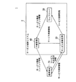
図1は、本発明の一実施形態であるサービス制御装置を適用した通信システムの基本構成を概念的に示した構成図である。同図に示すように、通信システム1は、サービス制御システム2と、通信端末10とを含んで構成される。また、サービス制御システム2は、サービス制御装置20と、ウェブサーバ30と、中継装置40とを含んで構成される。通信端末10と、サービス制御装置20と、ウェブサーバ30と、中継装置40との相互の通信は、図示しないネットワークを介して行われる。このネットワークは、コンピュータネットワーク、デジタル電話網等の電気通信回線である。
Hereinafter, embodiments for carrying out the present invention will be described in detail with reference to the drawings.
FIG. 1 is a configuration diagram conceptually showing the basic configuration of a communication system to which a service control apparatus according to an embodiment of the present invention is applied. As shown in the figure, the
なお、実際の通信システム1において、通信端末10は複数存在するが、説明を簡略化するために、図1には一台の通信端末10を図示する。また、実際のサービス制御システム2において、ウェブサーバ30および中継装置40は一または複数存在するが、これにおいても、同図には各一台のウェブサーバ30および中継装置40を図示する。
In the
通信端末10は、マルチタスク機能を有する情報処理端末である。マルチタスク機能とは、例えば、CPU(Central Processing Unit)が、複数のタスク(処理の実行単位)を切替えて実行する機能である。通信端末10は、例えば、コンテンツデータのダウンロード、ウェブサイトの閲覧、電子メールの作成および送受信、通話、オンラインゲームの実行等のサービスに対応するアプリケーションプログラムを、マルチタスク機能によって実行する。通信端末10は、例えば、携帯電話機、携帯情報端末(Personal Digital Assistants;PDA)、多機能携帯電話機(スマートフォン)等の携帯端末や、パーソナルコンピュータ等のコンピュータ装置により実現される。
The
複数のアプリケーションプログラムをマルチタスクで実行する通信端末10は、サービス利用状況情報をサービスごとに生成し、このサービス利用状況情報を所定のタイミングにしたがってサービス制御装置20に供給する。サービス利用状況情報は、通信端末10がサービスに対応するアプリケーションプログラムを起動している状態において、当該サービスの利用状況を定量化または定性化して表した利用状態値を含むデータテーブルである。サービス利用状況情報は、サービスの利用履歴を示す情報でもある。所定のタイミングは、例えば、3秒〜5秒の時間間隔による周期的なタイミングである。サービス利用状況情報のデータ構成の具体例については後述する。
The
また、通信端末10は、サービス制御装置20から供給されるサービス制御情報を取り込み、このサービス制御情報に基づいて、サービスに対応するアプリケーションプログラムの実行に関するハードウェア環境のリソース割当てや、ネットワーク環境のリソース割当てを行う。ハードウェア環境のリソースとは、例えば、CPUやメモリ等の計算資源である。また、ネットワーク環境のリソースとは、例えば、データ伝送の割当帯域やデータ伝送の順番等である。
Further, the
また、通信端末10は、中継装置40から供給されるサービス情報およびコンテンツ情報またはいずれかを取り込んでユーザに利用させる。サービス情報は、ウェブ閲覧サービスに対するウェブデータ、通話サービスに対する音声データ、電子メールサービスに対する電子メール等である。コンテンツ情報は、ダウンロードサービスに対するコンテンツデータ等である。
Further, the
サービス制御装置20は、複数の通信端末10それぞれからサービス利用状況情報の提供を受けるたびにこのサービス利用状況情報を取り込んでデータベースに格納する。サービス制御装置20は、そのデータベースに格納されたサービス利用状況情報を解析して通信端末10ごとのサービス制御情報を生成し、各サービス制御情報を対応する通信端末10とウェブサーバ30と中継装置40とに供給する。サービス制御装置20は、例えば、コンピュータ装置やサーバ装置等により実現される。
Each time the
ウェブサーバ30は、通信端末10からの要求に応じて、サービス情報およびコンテンツ情報、すなわち、HTML(Hyper Text Markup Language)および画像データ等のオブジェクトを、要求元である通信端末10に対して供給するサーバ装置である。
また、ウェブサーバ30は、サービス制御装置20から供給されるサービス制御情報を取り込み、このサービス制御情報に基づいてネットワーク環境のリソース割当てを行う。
In response to a request from the
Further, the
中継装置40は、通信端末10とウェブサーバ30との間の通信を中継する装置である。中継装置40は、例えば、ルータ、プロキシサーバ、無線LAN(Local Area Network)のアクセスポイント等のネットワーク装置、および無線基地局等の基地局により実現される。
中継装置40は、サービス制御装置20から供給されるサービス制御情報を取り込み、このサービス制御情報に基づいてネットワーク環境のリソース割当てを行う。例えば、サービス制御情報に示される内容が、通信端末10に対するサービス提供の品質を下げる指示である場合、中継装置40は、通信端末10に対するパケット伝送の優先度を下げたり、ウィンドウサイズを小さくしたりする。
中継装置40は、ウェブサーバ30から供給されるサービス情報およびコンテンツ情報を取り込み、サービス制御情報に基づいて制御された状態でこれらサービス情報およびコンテンツ情報を、要求元である通信端末10に供給する。
The
The
The
次に、通信端末10が取得するサービス利用状況情報について説明する。
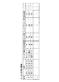
図2は、サービス利用状況情報の、おおよそのデータ構成の例を示す図である。同図に示すように、サービス利用状況情報は、例えば、番号と、日時と、サービス種別と、利用頻度と、タスク状態と、フォアグラウンド率と、操作頻度との各項目(列)を含むデータテーブルである。サービス利用状況情報のレコード(行)は、サービスごと、すなわち、通信端末10によって起動されるアプリケーションプログラムごとに設けられる。
Next, service usage status information acquired by the
FIG. 2 is a diagram illustrating an example of an approximate data configuration of service usage status information. As shown in the figure, the service usage status information includes, for example, a data table including items (columns) of number, date / time, service type, usage frequency, task status, foreground rate, and operation frequency. It is. A record (row) of service usage status information is provided for each service, that is, for each application program activated by the
項目「番号」には、通信端末10が起動しているアプリケーションプログラムを識別する情報(識別情報)が代入される。識別情報は、例えば、文字、数字、および記号のいずれかまたは組み合わせである。
なお、サービス利用状況情報を複数のデータテーブルで構成する場合、または、サービス利用状況情報に他のデータテーブルを対応付ける場合、項目「番号」を主キーとする。
In the item “number”, information (identification information) for identifying the application program in which the
When the service usage status information is composed of a plurality of data tables, or when other data tables are associated with the service usage status information, the item “number” is used as the main key.
項目「日時」には、レコードが作成されたとき、およびレコードのデータが更新されたときの日時の情報(日時情報)が代入される。日時情報は、例えば、“年月日”および“時分秒”である。
項目「サービス種別」には、サービスの種別を示す情報(サービス種別情報)が代入される。サービス種別情報は、例えば、“ダウンロード”、“ウェブ閲覧”、“電子メール”、“通話”、“ゲーム”等である。
In the item “date and time”, date and time information (date and time information) when the record is created and when the data of the record is updated is substituted. The date information is, for example, “year / month / day” and “hour / minute / second”.
In the item “service type”, information indicating the type of service (service type information) is substituted. The service type information is, for example, “download”, “web browsing”, “e-mail”, “call”, “game”, and the like.
項目「利用頻度」には、通信端末10のユーザによる、過去の一定期間におけるサービスの利用の頻度、言い換えると、通信端末10が、過去の一定期間において、そのサービスに対応するアプリケーションプログラムを実行した時間の割合が、定性的な情報(利用頻度情報)に変換されて代入される。過去の一定期間は、例えば、24時間、1ヶ月、1週間等であり、ユーザによって任意に変更可能である。定性的な情報である利用頻度情報は、例えば、“特”、“高”、“中”、“低”等である。通信端末10がアプリケーションプログラムを過去の一定期間において実行した時間の割合をUとする場合、利用頻度情報は、例えば、Uが25%未満である場合は“低”、25%以上50%未満である場合は“中”、50%以上75%未満である場合は“高”、および75%以上である場合は“特”である。
In the item “usage frequency”, the frequency of use of the service in the past fixed period by the user of the
なお、項目「利用頻度」には、過去の一定期間におけるアプリケーションプログラムの起動回数が、定性的な情報に変換されて代入されてもよい。また、項目「利用頻度」には、定性的な情報に限らず、時間の割合またはアプリケーションプログラムの起動回数そのものが代入されてもよい。 In the item “usage frequency”, the number of times the application program has been started in a past fixed period may be converted into qualitative information and substituted. In addition, the item “usage frequency” is not limited to qualitative information, and a time ratio or the number of times the application program is started may be substituted.
項目「タスク状態」には、通信端末10が、サービスに対応するアプリケーションプログラムを、フォアグラウンドで実行しているか、またはバックグラウンドで実行しているかを示す情報(タスク状態情報)が代入される。フォアグラウンドは、アプリケーションプログラムがユーザによる操作対象となって実行される状態のことである。また、バックグラウンドは、アプリケーションプログラムがユーザによる操作対象とならずに実効される状態のことである。例えば、項目「タスク状態」には、フォアグラウンドを示す情報として“FG”、バックグラウンドを示す情報として“BG”が代入される。
Information (task state information) indicating whether the
項目「フォアグラウンド率」には、サービスに対応するアプリケーションプログラムの実行時間において、そのアプリケーションプログラムがフォアグラウンドで実行される時間的割合(フォアグラウンド率情報)が代入される。実行時間とは、例えば、アプリケーションプログラムの起動時刻から現在時刻までの時間である。 In the item “foreground rate”, a time ratio (foreground rate information) in which the application program is executed in the foreground in the execution time of the application program corresponding to the service is substituted. The execution time is, for example, the time from the start time of the application program to the current time.
項目「操作頻度」には、サービスに対応するアプリケーションプログラムの実行中における、ユーザによる操作の頻度(操作頻度情報)が代入される。例えば、項目「操作頻度」には、サービスに対応するアプリケーションプログラムの実行時間に対する、そのアプリケーションプログラムの実行に関連するキー操作の時間とポインタ操作の時間との合計時間の割合を、例えば0から1までの間で正規化した値が格納される。
サービス利用状況情報において、タスク状態情報とフォアグラウンド率情報と操作頻度情報とは、アプリケーションプログラムに対するユーザの集中度(ユーザ集中度)を表す。
In the item “operation frequency”, the frequency of operation by the user (operation frequency information) during execution of the application program corresponding to the service is substituted. For example, in the item “operation frequency”, the ratio of the total time of the key operation time and the pointer operation time related to the execution of the application program to the execution time of the application program corresponding to the service is, for example, 0 to 1 Stores the value normalized between 1 and 2.
In the service usage status information, task status information, foreground rate information, and operation frequency information represent the degree of user concentration (user concentration) with respect to the application program.
なお、サービス利用状況情報に、コンテンツデータのサイズや伝送レート等の通信に関する情報を含めさせてもよい。 The service usage information may include information related to communication such as the content data size and transmission rate.
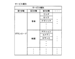
図3は、サービス利用状況情報における項目「サービス種別」の、さらに詳細なデータ構成の体系を示す図である。同図に示すように、サービスがダウンロードサービスである場合の項目「サービス種別」は、第1分類、第2分類、第3分類、・・・等の項目にさらに区分される。項目「第1分類」には、サービス種別情報、例えば“ダウンロード”が代入される。項目「第2分類」には、コンテンツの種別を示す情報(コンテンツ種別情報)が代入される。例えば、項目「第2分類」には、音楽コンテンツを示す“音楽”、映画コンテンツを示す“映画”、書籍コンテンツを示す“書籍”等が代入される。項目「第3分類」には、ジャンルを示す情報(ジャンル情報)が代入される。例えば、項目「第3分類」には、音楽のジャンルを示す“ジャズ”、“ロック”、“クラシック”等、映画のジャンルを示す“アクション”、“コメディ”、“ロマンス”等、書籍のジャンルを示す“小説”、“学術”、“辞書”等が代入される。さらに、「第4分類」以降の項目には、コンテンツの制作年代、制作国、製作者等のコンテンツに関する各種情報が代入されてもよい。 FIG. 3 is a diagram showing a more detailed data configuration system of the item “service type” in the service usage status information. As shown in the figure, the item “service type” when the service is a download service is further classified into items such as a first category, a second category, a third category,. In the item “first classification”, service type information such as “download” is substituted. Information (content type information) indicating the type of content is assigned to the item “second classification”. For example, “music” indicating music content, “movie” indicating movie content, “book” indicating book content, and the like are assigned to the item “second classification”. Information indicating the genre (genre information) is assigned to the item “third classification”. For example, the item “3rd classification” includes “jazz”, “rock”, “classic”, etc. indicating the genre of music, and “action”, “comedy”, “romance”, etc., indicating the genre of the movie. “Novel”, “Academic”, “Dictionary”, etc. are substituted. Further, in the items after “fourth classification”, various types of information regarding the content such as the production date of the content, the country of production, and the producer may be substituted.
具体的には、例えば、通信端末10がアクション映画のコンテンツをダウンロードする場合、サービス利用状況情報のサービス種別には、第1分類として“ダウンロード”、第2分類として“映画”、第3分類として“アクション”が代入される。これらサービス種別は、コンテンツの属性情報である。
Specifically, for example, when the
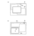
図4(a)(b)は、通信端末10が三つのアプリケーションプログラムをマルチタスクで実行する場合の画面表示の例を模式的に示す図である。同図(a)は、第1のアプリケーションプログラム〜第3のアプリケーションプログラムそれぞれに対応するウィンドウ61a,61b,61cが、通信端末10の表示画面61に表示された様子を示している。同図(a)では、ウィンドウ61aが最も手前に表示、つまり、他のウィンドウ61b,61cによって隠されることなく表示画面61に表示されている。通信端末10は、最も手前に表示されるウィンドウ61aを検出し、このウィンドウ61aに対応する第1のアプリケーションプログラムを、フォアグラウンドで実行されているプログラムとして選出する。
4A and 4B are diagrams schematically illustrating an example of screen display when the
また、図4(b)は、第1のアプリケーションプログラム〜第3のアプリケーションプログラムそれぞれに対応するウィンドウ62a,62b,62cが、通信端末10の表示画面62に表示された様子を示している。同図(b)において、ウィンドウ62aは他のウィンドウ62b,62cに重なっていないが、通信端末10によって選択されているウィンドウである。具体的には、ウィンドウ62aは、通信端末10の制御によるポインタ63によって操作されているウィンドウである。通信端末10は、選択されているウィンドウ、例えば、ポインタ63によって操作されているウィンドウ62aを検出し、このウィンドウ62aに対応する第1のアプリケーションプログラムを、フォアグラウンドで実行されているプログラムとして選出する。
なお、通信端末10は、キーによって操作されているウィンドウ62aに対応する第1のアプリケーションプログラムを、フォアグラウンドで実行されているプログラムとして選出してもよい。
4B shows a state in which
Note that the
次に、通信端末10の機能構成について説明する。
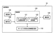
図5は、通信端末10の機能構成を示すブロック図である。同図に示すように、通信端末10は、サービス利用状況情報記憶部110と、制御部120と、通信部130と、通話部140と、操作部150とを備える。
Next, the functional configuration of the
FIG. 5 is a block diagram illustrating a functional configuration of the
サービス利用状況情報記憶部110は、図2および図3によるサービス利用状況情報を記憶する。サービス利用状況情報記憶部110は、例えば書き込みおよび読み出し可能な半導体記憶装置(メモリ)により実現される。
The service usage status
制御部120は、図示しないCPUおよび記憶部により実現される。CPUは、記憶部に記憶された制御プログラムを読み出して実行することにより、通信端末10全体を制御する。また、CPUは、記憶部に記憶された一または複数のアプリケーションプログラムを読み出して実行する。CPUは、複数のアプリケーションプログラムを実行する場合は、マルチタスクにより実行する。CPUが実行するアプリケーションプログラムは、例えば、コンテンツデータのダウンロードアプリケーション、ウェブブラウザ、電子メールクライアント、音声通話アプリケーション、ゲームアプリケーション等である。
The
制御部120は、その機能構成として、サービス利用状態取得部121と、サービス制御処理部122とを備える。
サービス利用状態取得部121は、サービスごと、言い換えると、CPUが起動しているアプリケーションプログラムごとに各種の利用状態を監視して利用状態値を取得する。そして、サービス利用状態取得部121は、利用状態に変化があったときの利用状態値で、サービス利用状況情報記憶部110に記憶されたサービス利用状況情報を更新する。
サービス制御処理部122は、サービス制御装置20から供給されるサービス制御情報を、通信部130を介して取り込む。そして、サービス制御処理部122は、取り込んだサービス制御情報に基づいて、サービスに対応するアプリケーションプログラムの実行に関するハードウェア環境のリソース割当てや、ネットワーク環境のリソース割当てを行う。
The
The service usage
The service
通信部130は、サービス制御装置20および中継装置40と通信する通信インタフェイスである。例えば、通信部130は、制御部120から供給されるサービス利用状況情報を取り込み、このサービス利用状況情報をサービス制御装置20に供給する。また、通信部130は、サービス制御装置20から供給されるサービス制御情報を取り込み、このサービス制御情報を制御部120に供給する。また、通信部130は、中継装置40から供給されるサービス情報およびコンテンツ情報を取り込み、これらサービス情報およびコンテンツ情報を制御部120に供給する。
The
通話部140は、電話機能を備えており、制御部120が音声通話アプリケーションを実行することにより機能する。
操作部150は、キー、タッチパネル、ポインティングデバイス等の操作受付部を備えた操作インタフェイスである。操作部150は、ユーザによる操作を受け付けて操作信号を生成し、この操作信号を制御部120に供給する。
The calling
The
次に、サービス制御装置20の機能構成について説明する。
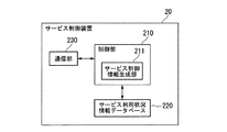
図6は、サービス制御装置20の機能構成を示すブロック図である。同図に示すように、サービス制御装置20は、制御部210と、サービス利用状況情報データベース220と、通信部(サービス利用状況情報取得部、サービス制御情報供給部)230とを備える。
Next, the functional configuration of the
FIG. 6 is a block diagram showing a functional configuration of the
制御部210は、図示しないCPUおよび記憶部により実現される。CPUは、記憶部に記憶されたサービス制御プログラムを読み出して実行することにより、サービス制御装置20全体を制御する。制御部210は、通信端末10から供給されるサービス利用状況情報を、通信部230を介して取り込み、このサービス利用状況情報をサービス利用状況情報データベース220に供給する。
制御部210は、その機能構成として、サービス制御情報生成部211を備える。サービス制御情報生成部211は、サービス利用状況情報データベース220に格納されたサービス利用状況情報を解析して、通信端末10ごとのサービス制御情報を生成する。
The
The
サービス利用状況情報データベース220は、制御部210から供給されるサービス利用状況情報を取り込んで、このサービス利用状況情報を送信元の通信端末10を特定する情報(例えば、端末番号やアドレス情報)とともに格納する。サービス利用状況情報データベース220は、例えば、磁気ハードディスク装置により実現される。
The service usage
通信部230は、通信端末10および中継装置40と通信する通信インタフェイスである。例えば、通信部230は、複数の通信端末10それぞれから供給されるサービス利用状況情報を取り込み、このサービス利用状況情報を制御部210に供給する。また、通信部230は、制御部210から供給されるサービス制御情報を取り込み、このサービス制御情報を対応する通信端末10とウェブサーバ30と中継装置40とに供給する。
The
次に、通信システム1の動作について、通信端末10が実行するサービス利用状況情報送信処理と、通信端末10が実行するサービス利用状態取得処理と、サービス制御装置20が実行するサービス制御情報生成処理とに分けてそれぞれ説明する。
Next, regarding the operation of the
図7は、通信端末10が実行するサービス利用状況情報送信処理の手順を示すフローチャートである。通信端末10の制御部120は、制御プログラムを実行することによって、本フローチャートによるサービス利用状況情報送信処理を実行する。
FIG. 7 is a flowchart showing a procedure of service usage status information transmission processing executed by the
まず、ステップS1において、制御部120は、サービス利用状況情報記憶部110からサービス利用状況情報を読み込む。
次に、ステップS2において、制御部120は、読み込んだサービス利用状況情報を通信部130に供給する。
通信部130は、制御部120から供給されたサービス利用状況情報を取り込んでこのサービス利用状況情報をパケット化し、このパケットデータをサービス制御装置20に対して送信する。
次に、ステップS3において、制御部120は、所定の時間が経過するまで待ち状態にし(S3:NO)、その所定の時間が経過したときに、ステップS1の処理に戻す(S3:YES)。所定の時間、つまり周期は、例えば3秒〜5秒である。
First, in step S <b> 1, the
Next, in step S <b> 2, the
The
Next, in step S3, the
図8は、通信端末10が実行するサービス利用状態取得処理の手順を示すフローチャートである。通信端末10の制御部120は、制御プログラムを実行することによって、本フローチャートによるサービス利用状態取得処理を実行する。ただし、同図のフローチャートは、アプリケーションプログラムごとに実行される処理手順を示している。
FIG. 8 is a flowchart illustrating a procedure of service use state acquisition processing executed by the
制御部120が一つのアプリケーションプログラムを起動すると、本フローチャートによる処理が開始される。まず、ステップS11において、制御部120は、サービス利用状況情報記憶部110にサービス利用状況情報が記憶されていない場合は、サービス利用状況情報のレコードを新規に作成し、サービス利用状況情報記憶部110にサービス利用状況情報が存在する場合は、そのサービス利用状況情報にレコードを追加する。例えば、制御部120は、図2および図3に示したサービス利用状況情報のレコードを新規作成または追加する。
When the
具体的には、制御部120は、起動したアプリケーションプログラムを識別する識別情報を「番号」に代入し、現在日時の情報を「日時」に代入し、起動したアプリケーションプログラムに対応するサービス種別情報を「サービス種別」に代入し、過去の一定期間において、そのサービスに対応するアプリケーションプログラムを実行した時間の割合を、定性的な情報に変換して得た利用頻度情報を「利用頻度」に代入し、「タスク状態」、「フォアグラウンド率」、「操作頻度」等の項目をヌル(null)としたレコードを新規作成または追加する。
Specifically, the
次に、ステップS12において、制御部120のサービス利用状態取得部121は、通信端末10の利用状態を監視して利用状態値を取得する。利用状態値は、例えば、アプリケーションプログラムのタスクの状態に応じた判定値と、アプリケーションプログラムのフォアグラウンド率と、アプリケーションプログラムの操作頻度とである。
Next, in step S12, the service usage
より具体的には、例えば、サービス利用状態取得部121は、アプリケーションプログラムがフォアグラウンドで実行されているか、バックグラウンドで実行されるかについてのタスクの状態を判定し、その判定結果に応じた判定値を取得する。判定の具体例としては、第1の例として、図4(a)に示したように、サービス利用状態取得部121は、アプリケーションプログラムに対応するウィンドウが最も手前に表示されるウィンドウであるか否かを調べることによって、フォアグラウンドで実行されているかバックグラウンドで実行されているかを判定する。また、第2の例として、同図(b)に示したように、サービス利用状態取得部121は、アプリケーションプログラムに対応するウィンドウがポインタやキーによって操作されているウィンドウであるか否かを調べることによって、フォアグラウンドで実行されているかバックグラウンドで実行されているかを判定する。
サービス利用状態取得部121は、判定結果がフォアグラウンドを示す結果である場合は、判定値を例えば“1”とし、判定結果がバックグラウンドを示す結果である場合は、判定値を例えば“0(ゼロ)”とする。
More specifically, for example, the service usage
When the determination result is a result indicating the foreground, the service use
また、例えば、サービス利用状態取得部121は、アプリケーションプログラムの実行時間において、そのアプリケーションプログラムがフォアグラウンドで実行される時間の割合を計算することによってフォアグラウンド率を取得する。
Further, for example, the service usage
また、例えば、サービス利用状態取得部121は、アプリケーションプログラムの実行時間に対する、そのアプリケーションプログラムの実行に関連するキー操作の時間とポインタ操作の時間との合計時間の割合を、例えば0から1までの間で正規化された値を計算することによって操作頻度を取得する。
Further, for example, the service usage
また、例えば、サービスがダウンロードサービスである場合は、サービス利用状態取得部121は、ダウンロード対象とするコンテンツデータに対応する属性情報、例えば、コンテンツ種別、ジャンル等を取得する。
For example, when the service is a download service, the service use
次に、図8におけるステップS13において、サービス利用状態取得部121は、直前のステップS12の処理において取得した利用状態値が前回取得した利用状態値から変化しているか否かを判定する。そして、サービス利用状態取得部121は、変化していると判定した場合、および直前のステップS12の処理において取得した利用状態値が最初の利用状態値である場合は、ステップS14の処理に移す。一方、サービス利用状態取得部121は、変化していないと判定した場合は、ステップS12の処理に戻す。
Next, in step S13 in FIG. 8, the service usage
ステップS14において、サービス利用状態取得部121は、変化していると判定した場合の利用状態値、および最初の利用状態値であると判定した場合の利用状態値で、レコードのデータを更新する。
In step S <b> 14, the service usage
次に、ステップS15において、制御部120は、アプリケーションプログラムの実行が終了したか否かを判定し、実行が終了したと判定した場合は、本フローチャートの処理を終了させる。一方、制御部120は、実行が終了していないと判定した場合は、ステップS12の処理に戻す。
Next, in step S15, the
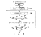
図9は、サービス制御装置20が実行するサービス制御情報生成処理の手順を示すフローチャートである。
まず、ステップS21において、通信部230はパケットデータの受信を受け付けている(S21:NO)。そして、通信部230が複数の通信端末10のうちいずれかから送信されたパケットデータを受信すると(S21:YES)、ステップS22の処理に移る。
FIG. 9 is a flowchart illustrating a procedure of service control information generation processing executed by the
First, in step S21, the
ステップS22において、通信部230は、受信したパケットデータからサービス利用状況情報を取り出して、このサービス利用状況情報を制御部210に供給する。
次に、制御部210は、通信部230から供給されるサービス利用状況情報を取り込んで、このサービス利用状況情報をサービス利用状況情報データベース220に供給する。
次に、サービス利用状況情報データベース220は、制御部210から供給されるサービス利用状況情報を取り込んで、このサービス利用状況情報を送信元の通信端末10を特定する端末番号やアドレス情報とともに格納する。
In step S <b> 22, the
Next, the
Next, the service usage
次に、ステップS23において、制御部210のサービス制御情報生成部211は、サービス利用状況情報データベース220に格納された、複数の通信端末10分のサービス利用状況情報に基づいて、サービス制御を行うか否かを判定する。
Next, in step S <b> 23, the service control
ステップS23における判定処理について、具体的に、複数の通信端末10が一斉にウェブサーバ30にアクセスしてコンテンツをダウンロードする状況を例として説明する。この状況が発生すると、通信システム1におけるネットワークのスループットが低下したり、輻輳が発生したりすることにより、ウェブサーバ30は、コンテンツを要求する全ての通信端末10に対して低品質なサービスを提供することとなる。そこで、サービス制御情報生成部211は、サービス利用状況情報データベース220に格納された、複数の通信端末10分のサービス利用状況情報に基づいて、例えば、ウェブサーバ30に同時期にアクセス(同時アクセスを含む)する通信端末10の台数があらかじめ決定された所定の台数を超える場合に、サービス制御を行うと判定する。
The determination process in step S23 will be specifically described by taking as an example a situation where a plurality of
次に、ステップS24において、サービス制御情報生成部211は、サービス利用状況情報データベース220に格納された、複数の通信端末10分のサービス利用状況情報を解析する。例えば、サービス制御情報生成部211は、サービス利用状況情報データベース220に格納された、複数の通信端末10から収集したサービス状況利用情報を参照し、通信端末ごとにサービス制御の優先度を決定する。
Next, in step S <b> 24, the service control
具体的に、サービス制御情報生成部211は、コンテンツのダウンロード処理をフォアグラウンドで実行している通信端末10や、コンテンツのダウンロード処理に意識を集中させているユーザの通信端末10に対しては、比較的高い品質のサービスを提供するように優先度を決定する。一方、サービス制御情報生成部211は、コンテンツのダウンロード処理をバックグラウンドで実行している通信端末10や、コンテンツのダウンロード処理に意識を集中させていないユーザの通信端末10に対しては、比較的低い品質のサービスを提供するように優先度を決定する。
Specifically, the service control
ここで、優先度の決定方法について説明する。例えば、サービス制御情報生成部211は、サービス利用状況情報データベース220に格納されたサービス状況利用情報を参照し、制御対象となるダウンロードサービスに対する各通信端末10の利用状態のスコアSを下記の式(1)により計算する。この式(1)は、C,U,R,Hを引数とした関数fで表される。Cは、タスク状態情報に応じた値であり、例えば、“FG”および“BG”それぞれに対応して“10”および“1”とする。Uは、利用頻度情報に応じた値であり、例えば、“特”、“高”、“中”、および“低”それぞれに対応して“0.8”、“0.6”、“0.4”、および“0.2”とする。Rは、例えば、フォアグラウンド率情報である。Hは、例えば、操作頻度情報である。
Here, a method for determining the priority will be described. For example, the service control

式(1)による関数fは、例えば、引数を積算および加算またはいずれかの演算を行う関数である。
なお、サービス制御情報生成部211は、関数fにおける引数C,U,R,Hそれぞれに任意の重みを付けて、スコアSを計算するようにしてもよい。また、サービス利用状況情報データベース220に、通信端末10ごとの、ユーザの趣味や好みに関する嗜好情報をあらかじめ登録しておき、サービス制御情報生成部211が、嗜好情報と、サービス種別情報におけるコンテンツ種別情報やジャンル情報等の属性情報とのマッチ度を計算することによってスコアSを求めてもよい。
The function f according to the expression (1) is a function that performs, for example, integration and addition of arguments or any calculation.
The service control
サービス制御情報生成部211は、計算して得たスコアSを正規化した値、またはスコアSそのものを優先度として得る。
The service control
次に、ステップS25において、サービス制御情報生成部211は、解析結果、つまり優先度に基づいてサービス制御情報を生成する。例えば、サービス制御情報生成部211は、通信端末10ごとに優先度に応じて割当帯域を計算し、優先度と割当帯域の情報とを含むサービス制御情報を生成する。具体例として、サービス制御情報生成部211は、ユーザiの通信端末10に対する割当帯域Wを、下記の式(2)により計算する。ただし、Mは、利用可能な帯域、Siは、ユーザiの通信端末10におけるスコアである。
Next, in step S25, the service control
次に、ステップS26において、サービス制御情報生成部211は、サービス制御情報を通信部230に供給する。
通信部230は、サービス制御情報生成部211から供給されたサービス制御情報を取り込んでこのサービス制御情報をパケット化し、このパケットデータをユーザ端末10とウェブサーバ30と中継装置40とに対して送信する。
次に、制御部210は、ステップS21の処理に戻す。
Next, in step S <b> 26, the service control
The
Next, the
次に、通信端末10のサービス制御の実行処理について、コンテンツのダウンロードを例に説明する。
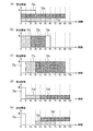
図10(a)〜(e)は、一台の通信端末10が三つのコンテンツをダウンロードする場合の、その通信端末10に対する帯域制御の例を概念的に示す図である。同図(a)〜(e)いずれとも、横軸を時間、縦軸を割当帯域として表している。横軸におけるtは所定の単位時間(例えば10秒)である。
Next, the execution process of the service control of the
FIGS. 10A to 10E are diagrams conceptually illustrating an example of bandwidth control for the
図10(a)は、通信端末10が、三つのコンテンツデータを並行してダウンロードする場合の帯域制御の例である。同図(a)によれば、通信端末10は、割当帯域Wの略三分の一(三分の一を含む)の帯域で、コンテンツデータ71a,72a,73aのダウンロードを同時に、すなわち優先順位をつけることなく開始し、“3t”時間経過後にコンテンツデータ73aのダウンロードを完了させ、“6t”時間経過後にコンテンツデータ71aのダウンロードを完了させ、“9t”時間経過後にコンテンツデータ72aのダウンロードを完了させている。
同図(a)の帯域制御は、ウェブサーバ30に対する各通信端末10からのアクセス率が比較的低く、ネットワークのスループットが所定の基準以下とならない場合の例である。
FIG. 10A is an example of bandwidth control when the
The bandwidth control in FIG. 6A is an example in the case where the access rate from each
図10(b),(c)は、通信端末10が、割当帯域W全てを各コンテンツデータのダウンロードに割当て、三つのコンテンツデータを直列にダウンロードする場合の帯域制御の例である。同図(b)によれば、通信端末10は、割当帯域W全ての帯域で、コンテンツデータ71bを“2t”時間をかけてダウンロードし、次に、コンテンツデータ72bを“3t”時間をかけてダウンロードし、次に、コンテンツデータ73bを“t”時間をかけてダウンロードしている。
同図(b)の帯域制御は、ウェブサーバ30に対する各通信端末10からのアクセス率が比較的低く、コンテンツデータ71b,72b,73bのうち、コンテンツデータ71bのダウンロードの優先度が一番高く、コンテンツデータ73bのダウンロードの優先度が一番低い場合の例である。
FIGS. 10B and 10C show examples of bandwidth control in the case where the
In the bandwidth control in FIG. 5B, the access rate from each
図10(b)のように、コンテンツデータ71b,72b,73bを、最も優先度が高いコンテンツデータ71bからダウンロードさせることにより、通信端末10は、最も優先度が高い(例えば、最も興味がある)コンテンツデータから再生を行うことができるため、ユーザに高い満足度を与えることができる。
As shown in FIG. 10B, the content terminal 71b, 72b, 73b is downloaded from the content data 71b having the highest priority so that the
また、図10(c)によれば、通信端末10は、割当帯域W全ての帯域で、コンテンツデータ73cを“t”時間をかけてダウンロードし、次に、コンテンツデータ71cを“2t”時間をかけてダウンロードし、次に、コンテンツデータ72cを“6t”時間をかけてダウンロードしている。
同図(c)の帯域制御は、ウェブサーバ30に対する各通信端末10からのアクセス率が比較的低く、コンテンツデータ71c,72c,73cのダウンロードの順番を、データ量が少ないほど優先度が高くなるように設定した場合の例である。
Further, according to FIG. 10C, the
In the bandwidth control in FIG. 6C, the access rate from each
図10(c)のように、コンテンツデータ71c,72c,73cのうち、データ量が最も少ない、すなわち最も早く取得可能なコンテンツデータ73cを、最初にダウンロードさせることにより、通信端末10は、いち早くコンテンツデータ73cの再生を行うことができるため、ユーザに高い満足度を与えることができる。
As shown in FIG. 10 (c), the
図10(d)は、通信端末10が、割当帯域W全てを第一番目のコンテンツデータのダウンロードに割当て、また、割当帯域Wの略三分の一(三分の一を含む)の帯域を第二番目および第三番目のコンテンツデータに割当てて、これら三つのコンテンツデータを直列にダウンロードする場合の帯域制御の例である。同図(d)によれば、通信端末10は、割当帯域W全ての帯域で、コンテンツデータ73dを“t”時間をかけてダウンロードし、次に、割当帯域Wの三分の一の帯域で、コンテンツデータ71dを“3t”時間をかけてダウンロードし、次に、コンテンツデータ72dを“6t”時間をかけてダウンロードしている。
同図(d)の帯域制御は、ウェブサーバ30に対する各通信端末10からのアクセス率が比較的高く、コンテンツデータ71d,72d,73dの順番を、優先度が高い順、またはコンテンツデータのデータ量が少ない順に設定した場合の例である。
FIG. 10D shows that the
The bandwidth control in FIG. 6D has a relatively high access rate from each
図10(d)のように、コンテンツデータ71d,72d,73dのうち、優先度が最も高いコンテンツデータ73dを、最も早くダウンロードさせることにより、通信端末10は、いち早くコンテンツデータ73dの再生を行うことができ、ユーザに高い満足度を与えることができる。さらに、ユーザは、ダウンロード後すぐにコンテンツデータ73dの再生を行う可能性があり、この場合、ユーザの注目は再生中のコンテンツに向けられる。このとき、コンテンツデータ71d,72dのダウンロードに対する注目度が低くなることが期待され、コンテンツデータ71d,72dの使用帯域を狭くしても、ユーザの満足度への影響は小さいものと考えられる。そこで、コンテンツデータ71d,72dの使用帯域を狭くした分、他の通信端末10の使用帯域を広くすることが可能となる。
As illustrated in FIG. 10D, the
また、図10(e)の帯域制御は、ウェブサーバ30に対する各通信端末10からのアクセス率が比較的高く、コンテンツデータ73eのダウンロードの優先度が他の二つのコンテンツデータ71e,72eのダウンロードの優先度よりも顕著に高い場合の例である。
Also, the band control of FIG. 10 (e) access rate from the
以上説明したとおり、本発明の一実施形態であるサービス制御装置2を適用した通信システム1において、複数のサービスそれぞれに対応するアプリケーションプログラムをマルチタスクで実行可能な通信端末10は、実行中のアプリケーションプログラムごとに、サービスの利用履歴と当該アプリケーションプログラムに対するユーザの集中度とを示すサービス利用状況情報を取得し、例えば定期的にサービス制御装置20に供給するようにした。
また、サービス制御装置20は、通信端末10から供給されるサービス利用状況情報を取り込んでデータベース化し、このデータベース化されたサービス利用状況情報に基づいて、複数の通信端末10に対するサービス制御の優先度を決定し、この優先度に基づいて、複数の通信端末10それぞれのサービス制御情報を生成して、対応する通信端末10に供給するようにした。
また、通信端末10は、サービス制御装置20から供給されるサービス制御情報を取り込み、このサービス制御情報に基づいてハードウェア環境のリソース割当てや、ネットワーク環境のリソース割当てを行うようにした。
As described above, in the
Further, the
Further, the
このように構成したことにより、サービス制御装置20は、複数の通信端末10それぞれのマルチタスクによるアプリケーションプログラムの実行状態、言い換えると、サービスの利用状態に応じて、ユーザのサービス利用に関する満足感を損なうことなく、あるいは高く維持しつつ、システム全体としてのリソース割当てを効率的に行うことができる。
すなわち、本実施形態によれば、マルチタスクシステムによって通信サービスを利用するユーザの満足度を高く維持させることができる。
With this configuration, the
That is, according to the present embodiment, it is possible to maintain a high degree of satisfaction for users who use communication services by the multitask system.
なお、通信端末10が、サービス制御装置20の機能を備えることにより、自律的にサービス制御を実行するようにしてもよい。
Note that the
また、上述した実施形態におけるサービス制御装置の一部、例えば、制御部220の機能をコンピュータで実現するようにしてもよい。この場合、その制御機能を実現するためのサービス制御プログラムをコンピュータ読み取り可能な記録媒体に記録して、この記録媒体に記録されたサービス制御プログラムをコンピュータシステムに読み込ませ、実行することによって実現してもよい。なお、ここでいう「コンピュータシステム」とは、OS(Operating System)や周辺装置のハードウェアを含むものである。また、「コンピュータ読み取り可能な記録媒体」とは、フレキシブルディスク、光磁気ディスク、光ディスク、メモリカード等の可搬型記録媒体、コンピュータシステムに内蔵される磁気ハードディスク等の記憶装置のことをいう。さらに「コンピュータ読み取り可能な記録媒体」とは、インターネット等のネットワークや電話回線等の通信回線を介してプログラムを送信する場合の通信線のように、短時間の間、動的にプログラムを保持するもの、その場合のサーバ装置やクライアントとなるコンピュータシステム内部の揮発性メモリのように、一定時間プログラムを保持するものを含んでもよい。また上記のプログラムは、前述した機能の一部を実現するためのものであってもよく、さらに前述した機能をコンピュータシステムにすでに記録されているプログラムとの組み合わせにより実現するものであってもよい。
Moreover, you may make it implement | achieve a part of service control apparatus in embodiment mentioned above, for example, the function of the
以上、本発明の実施の形態について図面を参照して詳述したが、具体的な構成はその実施形態に限られるものではなく、本発明の要旨を逸脱しない範囲の設計等も含まれる。 As mentioned above, although embodiment of this invention was explained in full detail with reference to drawings, the specific structure is not restricted to that embodiment, The design of the range which does not deviate from the summary of this invention, etc. are included.
1 通信システム
2 サービス制御システム
10 通信端末
20 サービス制御装置
30 ウェブサーバ
40 中継装置
110 サービス利用状況情報記憶部
120 制御部
121 サービス利用状態取得部
122 サービス制御処理部
130 通信部
140 通話部
150 操作部
210 制御部
211 サービス制御情報生成部
220 サービス利用状況情報データベース
230 通信部(サービス利用状況情報取得部、サービス制御情報供給部)
DESCRIPTION OF
Claims (6)
前記サービス利用状況情報取得部が取得したサービス利用状況情報に基づいて、前記複数の通信端末それぞれにおいて実行中のアプリケーションプログラム間の優先度を前記複数の通信端末それぞれについて決定し、前記優先度に基づいて、前記複数の通信端末それぞれのサービス制御情報を生成するサービス制御情報生成部と、
前記サービス制御情報生成部が生成した前記複数の通信端末それぞれのサービス制御情報を、対応する通信端末に供給するサービス制御情報供給部と、
を備えることを特徴とするサービス制御装置。 Service usage status indicating the service usage history and the user's concentration on the application program for each application program being executed from each of a plurality of communication terminals capable of executing multi-tasking application programs corresponding to the plurality of services. A service usage information acquisition unit for acquiring information;
Based on the service usage status information acquired by the service usage status information acquisition unit, a priority between the application programs being executed in each of the plurality of communication terminals is determined for each of the plurality of communication terminals , and based on the priority A service control information generating unit for generating service control information for each of the plurality of communication terminals;
A service control information supply unit that supplies service control information of each of the plurality of communication terminals generated by the service control information generation unit to a corresponding communication terminal;
A service control device comprising:
前記サービス利用履歴は、サービスの属性情報を含み、
前記サービス制御情報生成部は、前記サービスの属性情報と前記嗜好情報とに基づいてユーザの嗜好に応じた優先度を決定する
ことを特徴とする請求項1記載のサービス制御装置。 A preference information storage unit that stores in advance preference information about each user of the plurality of communication terminals;
The service usage history includes service attribute information,
The service control apparatus according to claim 1, wherein the service control information generation unit determines a priority according to a user's preference based on the attribute information of the service and the preference information.
複数のサービスそれぞれに対応するアプリケーションプログラムをマルチタスクで実行可能な複数の通信端末それぞれから、実行中のアプリケーションプログラムごとに、サービスの利用履歴と前記アプリケーションプログラムに対するユーザの集中度とを示すサービス利用状況情報を取得するサービス利用状況情報取得部と、
前記サービス利用状況情報取得部が取得したサービス利用状況情報に基づいて、前記複数の通信端末それぞれにおいて実行中のアプリケーションプログラム間の優先度を前記複数の通信端末それぞれについて決定し、前記優先度に基づいて、前記複数の通信端末それぞれのサービス制御情報を生成するサービス制御情報生成部と、
前記サービス制御情報生成部が生成した前記複数の通信端末それぞれのサービス制御情報を、対応する通信端末に供給するサービス制御情報供給部と、
として機能させるためのサービス制御プログラム。 Computer
Service usage status indicating the service usage history and the user's concentration on the application program for each application program being executed from each of a plurality of communication terminals capable of executing multi-tasking application programs corresponding to the plurality of services. A service usage information acquisition unit for acquiring information;
Based on the service usage status information acquired by the service usage status information acquisition unit, a priority between the application programs being executed in each of the plurality of communication terminals is determined for each of the plurality of communication terminals , and based on the priority A service control information generating unit for generating service control information for each of the plurality of communication terminals;
A service control information supply unit that supplies service control information of each of the plurality of communication terminals generated by the service control information generation unit to a corresponding communication terminal;
Service control program to function as.
Priority Applications (2)
| Application Number | Priority Date | Filing Date | Title |
|---|---|---|---|
| JP2011079024A JP5659066B2 (en) | 2011-03-31 | 2011-03-31 | Service control apparatus and service control program |
| US13/429,687 US20120254442A1 (en) | 2011-03-31 | 2012-03-26 | Service Control System Implementing Resource Allocation With Multitasking Communication Terminals |
Applications Claiming Priority (1)
| Application Number | Priority Date | Filing Date | Title |
|---|---|---|---|
| JP2011079024A JP5659066B2 (en) | 2011-03-31 | 2011-03-31 | Service control apparatus and service control program |
Publications (2)
| Publication Number | Publication Date |
|---|---|
| JP2012215943A JP2012215943A (en) | 2012-11-08 |
| JP5659066B2 true JP5659066B2 (en) | 2015-01-28 |
Family
ID=46928808
Family Applications (1)
| Application Number | Title | Priority Date | Filing Date |
|---|---|---|---|
| JP2011079024A Active JP5659066B2 (en) | 2011-03-31 | 2011-03-31 | Service control apparatus and service control program |
Country Status (2)
| Country | Link |
|---|---|
| US (1) | US20120254442A1 (en) |
| JP (1) | JP5659066B2 (en) |
Families Citing this family (10)
| Publication number | Priority date | Publication date | Assignee | Title |
|---|---|---|---|---|
| US9906608B2 (en) * | 2013-04-30 | 2018-02-27 | International Business Machines Corporation | Intelligent adaptation of mobile applications based on constraints and contexts |
| JP6055104B2 (en) * | 2013-09-11 | 2016-12-27 | フリービット株式会社 | Network connection system and method |
| US10165571B2 (en) | 2013-09-11 | 2018-12-25 | Freebit Co., Ltd. | Application state change notification program and method therefor |
| JP6207433B2 (en) * | 2014-03-11 | 2017-10-04 | Kddi株式会社 | Communication priority setting device, method and program |
| TWI602125B (en) * | 2014-04-17 | 2017-10-11 | 國立臺灣大學 | Resource allocation method |
| JP2016127531A (en) * | 2015-01-07 | 2016-07-11 | 日本電信電話株式会社 | Communication network system, network device therefor, communication band allocation control method and program |
| CN105391654A (en) | 2015-11-26 | 2016-03-09 | 中国建设银行股份有限公司 | Account activeness-based system resource allocation method and device |
| CN107481006B (en) * | 2017-08-24 | 2020-06-26 | 维沃移动通信有限公司 | Resource transfer method, server and terminal |
| CN110300218A (en) * | 2018-03-23 | 2019-10-01 | 中兴通讯股份有限公司 | Method for adjusting performance and device, terminal, storage medium, electronic device |
| JP2020154530A (en) * | 2019-03-19 | 2020-09-24 | Necソリューションイノベータ株式会社 | Resource management device, user device side resource management device, resource management method, user device side resource management method, program, and storage medium |
Family Cites Families (12)
| Publication number | Priority date | Publication date | Assignee | Title |
|---|---|---|---|---|
| JPH08190527A (en) * | 1995-01-09 | 1996-07-23 | Nippon Telegr & Teleph Corp <Ntt> | Service selection method and system therefor |
| JP2002078012A (en) * | 2000-08-30 | 2002-03-15 | Matsushita Electric Ind Co Ltd | Base station device, communication terminal and wireless communication method |
| US7493407B2 (en) * | 2002-08-14 | 2009-02-17 | Drs Technical Services, Inc. | Method and apparatus for controlling the allocation of bandwidth of a network access point to an application having a message transmitted on the network |
| EP1543419A2 (en) * | 2002-09-20 | 2005-06-22 | Koninklijke Philips Electronics N.V. | Method and system for allocating shared resources between applications |
| US8149771B2 (en) * | 2006-01-31 | 2012-04-03 | Roundbox, Inc. | Reliable event broadcaster with multiplexing and bandwidth control functions |
| US8549629B1 (en) * | 2009-03-16 | 2013-10-01 | Verint Americas Inc. | Classification and identification of computer use |
| JP2010278800A (en) * | 2009-05-29 | 2010-12-09 | Hitachi Ltd | Content processor and content processing method |
| JP5445914B2 (en) * | 2009-06-11 | 2014-03-19 | 日本電気株式会社 | Resource allocation system, resource allocation method, and resource allocation program |
| US9384054B2 (en) * | 2010-09-22 | 2016-07-05 | Nokia Technologies Oy | Process allocation to applications executing on a mobile device |
| US8635630B2 (en) * | 2010-10-25 | 2014-01-21 | Microsoft Corporation | Application lifetime management |
| US8893007B2 (en) * | 2010-11-09 | 2014-11-18 | Microsoft Corporation | Managing network usage per application via policies |
| US9398103B2 (en) * | 2011-04-15 | 2016-07-19 | Qualcomm Incorporated | Methods and apparatus for enhancing device performance through flow control |
-
2011
- 2011-03-31 JP JP2011079024A patent/JP5659066B2/en active Active
-
2012
- 2012-03-26 US US13/429,687 patent/US20120254442A1/en not_active Abandoned
Also Published As
| Publication number | Publication date |
|---|---|
| US20120254442A1 (en) | 2012-10-04 |
| JP2012215943A (en) | 2012-11-08 |
Similar Documents
| Publication | Publication Date | Title |
|---|---|---|
| JP5659066B2 (en) | Service control apparatus and service control program | |
| JP6339563B2 (en) | Personalized auto-generated electronic program guide for content delivery platform | |
| CN104782138B (en) | Thumbnail image selects system, method and computer-readable medium | |
| US9723067B2 (en) | Prioritized content transmission | |
| AU2013205553B2 (en) | Providing feedback via a social network from a media distribution platform | |
| CN109478142B (en) | Methods, systems, and media for presenting a user interface customized for predicted user activity | |
| CN104144357B (en) | Video broadcasting method and system | |
| KR20110057264A (en) | Method, system, and apparatus for ranking media sharing channels | |
| US20180270305A1 (en) | Systems and methods for throttling incoming network traffic requests | |
| US9866520B2 (en) | Method and apparatus for managing internet content | |
| JP5735023B2 (en) | Information providing apparatus, information providing method of information providing apparatus, information providing program, and recording medium | |
| KR20150020390A (en) | Content recommendation method, and apparatas and system for providing the method | |
| US20160352817A1 (en) | Predictive Peer Determination For Peer-to-Peer Digital Content Download | |
| US9565224B1 (en) | Methods, systems, and media for presenting a customized user interface based on user actions | |
| US9821223B2 (en) | Game retention value optimization system | |
| US20200403955A1 (en) | Systems and methods to prioritize chat rooms using machine learning | |
| CN103686223B (en) | A kind of method and apparatus that video access service is provided according to field feedback | |
| US9928224B1 (en) | Assigning slots to content in a pipeline | |
| JP5568537B2 (en) | CONTENT DISPLAY METHOD, CONTENT DISPLAY DEVICE, AND PROGRAM THEREOF | |
| KR20230019821A (en) | Editable video search and ranking in multimedia messaging applications | |
| CN113326397A (en) | Service data processing method and device | |
| US20120317186A1 (en) | Web based system and method for cross-site personalisation | |
| CN112533032B (en) | Video data processing method and device and storage medium | |
| CN114302187A (en) | Media resource playing method and device, electronic equipment and storage medium | |
| JP2019209056A (en) | Information display program, information display device, and information display method |
Legal Events
| Date | Code | Title | Description |
|---|---|---|---|
| A521 | Request for written amendment filed |
Free format text: JAPANESE INTERMEDIATE CODE: A821 Effective date: 20130821 |
|
| A621 | Written request for application examination |
Free format text: JAPANESE INTERMEDIATE CODE: A621 Effective date: 20130821 |
|
| A977 | Report on retrieval |
Free format text: JAPANESE INTERMEDIATE CODE: A971007 Effective date: 20140328 |
|
| A131 | Notification of reasons for refusal |
Free format text: JAPANESE INTERMEDIATE CODE: A131 Effective date: 20140408 |
|
| A521 | Request for written amendment filed |
Free format text: JAPANESE INTERMEDIATE CODE: A523 Effective date: 20140528 |
|
| A521 | Request for written amendment filed |
Free format text: JAPANESE INTERMEDIATE CODE: A821 Effective date: 20140529 |
|
| TRDD | Decision of grant or rejection written | ||
| A01 | Written decision to grant a patent or to grant a registration (utility model) |
Free format text: JAPANESE INTERMEDIATE CODE: A01 Effective date: 20141104 |
|
| A61 | First payment of annual fees (during grant procedure) |
Free format text: JAPANESE INTERMEDIATE CODE: A61 Effective date: 20141201 |
|
| R150 | Certificate of patent or registration of utility model |
Ref document number: 5659066 Country of ref document: JP Free format text: JAPANESE INTERMEDIATE CODE: R150 |