JP5659013B2 - System for monitoring pantograph damage and wear - Google Patents
System for monitoring pantograph damage and wear Download PDFInfo
- Publication number
- JP5659013B2 JP5659013B2 JP2010519308A JP2010519308A JP5659013B2 JP 5659013 B2 JP5659013 B2 JP 5659013B2 JP 2010519308 A JP2010519308 A JP 2010519308A JP 2010519308 A JP2010519308 A JP 2010519308A JP 5659013 B2 JP5659013 B2 JP 5659013B2
- Authority
- JP
- Japan
- Prior art keywords
- pantograph
- image
- sensor
- capture device
- image capture
- Prior art date
- Legal status (The legal status is an assumption and is not a legal conclusion. Google has not performed a legal analysis and makes no representation as to the accuracy of the status listed.)
- Expired - Fee Related
Links
Images


Classifications
-
- B—PERFORMING OPERATIONS; TRANSPORTING
- B60—VEHICLES IN GENERAL
- B60L—PROPULSION OF ELECTRICALLY-PROPELLED VEHICLES; SUPPLYING ELECTRIC POWER FOR AUXILIARY EQUIPMENT OF ELECTRICALLY-PROPELLED VEHICLES; ELECTRODYNAMIC BRAKE SYSTEMS FOR VEHICLES IN GENERAL; MAGNETIC SUSPENSION OR LEVITATION FOR VEHICLES; MONITORING OPERATING VARIABLES OF ELECTRICALLY-PROPELLED VEHICLES; ELECTRIC SAFETY DEVICES FOR ELECTRICALLY-PROPELLED VEHICLES
- B60L5/00—Current collectors for power supply lines of electrically-propelled vehicles
- B60L5/18—Current collectors for power supply lines of electrically-propelled vehicles using bow-type collectors in contact with trolley wire
- B60L5/22—Supporting means for the contact bow
- B60L5/24—Pantographs
-
- B—PERFORMING OPERATIONS; TRANSPORTING
- B60—VEHICLES IN GENERAL
- B60M—POWER SUPPLY LINES, AND DEVICES ALONG RAILS, FOR ELECTRICALLY- PROPELLED VEHICLES
- B60M1/00—Power supply lines for contact with collector on vehicle
- B60M1/12—Trolley lines; Accessories therefor
- B60M1/28—Manufacturing or repairing trolley lines
-
- G—PHYSICS
- G06—COMPUTING; CALCULATING OR COUNTING
- G06T—IMAGE DATA PROCESSING OR GENERATION, IN GENERAL
- G06T7/00—Image analysis
- G06T7/0002—Inspection of images, e.g. flaw detection
- G06T7/0004—Industrial image inspection
-
- B—PERFORMING OPERATIONS; TRANSPORTING
- B60—VEHICLES IN GENERAL
- B60L—PROPULSION OF ELECTRICALLY-PROPELLED VEHICLES; SUPPLYING ELECTRIC POWER FOR AUXILIARY EQUIPMENT OF ELECTRICALLY-PROPELLED VEHICLES; ELECTRODYNAMIC BRAKE SYSTEMS FOR VEHICLES IN GENERAL; MAGNETIC SUSPENSION OR LEVITATION FOR VEHICLES; MONITORING OPERATING VARIABLES OF ELECTRICALLY-PROPELLED VEHICLES; ELECTRIC SAFETY DEVICES FOR ELECTRICALLY-PROPELLED VEHICLES
- B60L2200/00—Type of vehicles
- B60L2200/26—Rail vehicles
Landscapes
- Engineering & Computer Science (AREA)
- Mechanical Engineering (AREA)
- Manufacturing & Machinery (AREA)
- Physics & Mathematics (AREA)
- General Physics & Mathematics (AREA)
- Theoretical Computer Science (AREA)
- Computer Vision & Pattern Recognition (AREA)
- Quality & Reliability (AREA)
- Power Engineering (AREA)
- Transportation (AREA)
- Current-Collector Devices For Electrically Propelled Vehicles (AREA)
- Image Analysis (AREA)
- Train Traffic Observation, Control, And Security (AREA)
Description
本明細書に記載の発明は機関車のパンタグラフに関するものである。具体的には、本発明は、自動的にパンタグラフの損傷および摩耗を監視するシステムに関するものである。しかしながら、本発明の技術範囲は必ずしもそれに限定されるものではない。 The invention described in this specification relates to a pantograph of a locomotive. Specifically, the present invention relates to a system for automatically monitoring pantograph damage and wear. However, the technical scope of the present invention is not necessarily limited thereto.
ほとんどの電気列車ではパンタグラフを用いて架空線から列車に電気が伝えられる。現代の高速電気列車のパンタグラフは炭素集電装置を備えている。通常、これらの炭素集電装置は、炭素ブロック支持体と、架空線に接触する炭素ブロックとを有している。炭素ブロックは、とりわけ、架空線の摩耗を最小限に抑えるように機能する。炭素ブロックに関する主要な問題は、炭素ブロックが割れやすいということである。電気区分装置の配列の狂い、過剰なアーク放電および持続する摩擦のすべてが炭素ブロックに重要な損傷をもたらす可能性を有している。検出されずに修理がされなければ、このような損傷は、パンタグラフにディワイヤメント(dewirement)および/または損傷を通常もたらすため、列車を動作不能とする恐れがある。パンタグラフへの損傷を検出するために、鉄道オペレータが定期的に手動で検査を行なうのが一般的である。このプロセスには、検査される列車のサービス拠点への再配置、架空線の電気的絶縁および列車の上側へのアクセスが必要となる。このような検査工程に関連する労務費および動作不能時間が望ましくないのは明白なことである。パンタグラフの手動による測定を回避するために複数のシステムが開発されている。英国特許第GB1374972号明細書および英国特許出願公開第GB2107662号明細書には、パンタグラフ集電装置の空洞内にチューブを挿入するパンタグラフ損傷測定システムが開示されている。パンタグラフが十分な損傷を受けた場合、これらのチューブが破裂してシステムの圧力が降下する。この降下が検出され、システムが自動的にパンタグラフを下げさせることにより、パンタグラフおよび/または架空線へさらなる損傷が防止されるようになっている。欧州特許出願公開第EP−A−0269307号明細書、西独国実用新案出願公開第DE−U−8803377.5号明細書および欧州特許出願公開第EP−A−0525595号明細書には、パンタグラフ集電装置の摩耗面の近傍に光ファイバが埋め込まれているシステムが開示されている。これらのファイバ内では光学信号が送信されており、あるファイバに損傷が生じた場合、そのファイバの光学信号が消えることにより、パンタグラフの損傷および/または摩耗が指摘されるようになっている。Engineering Integrity、第19巻、2006年3月、p.12−17に記載の他のアプローチでは、パンタグラフの炭素集電装置の摩耗を自動的に検出するためのレーザ支援イメージ処理技術が用いられている。 Most electric trains use pantographs to transmit electricity from overhead lines to the train. Modern high-speed electric train pantographs are equipped with a carbon current collector. Usually, these carbon current collectors have a carbon block support and a carbon block in contact with the overhead wire. The carbon block functions, among other things, to minimize wear on the overhead wire. The main problem with carbon blocks is that they are prone to cracking. Electrical misalignment arrangements, excessive arcing and sustained friction all have the potential to cause significant damage to the carbon block. If not detected and repaired, such damage usually results in dewiring and / or damage to the pantograph and can render the train inoperable. In order to detect damage to the pantograph, it is common for railroad operators to perform manual inspections periodically. This process requires relocation of the train to be inspected to the service location, electrical insulation of overhead lines and access to the upper side of the train. Clearly, labor costs and downtime associated with such inspection processes are undesirable. Several systems have been developed to avoid manual measurement of pantographs. GB 1374972 and GB 2207762 disclose a pantograph damage measurement system in which a tube is inserted into the cavity of a pantograph current collector. If the pantograph is sufficiently damaged, these tubes will rupture and the system pressure will drop. This drop is detected and the system automatically lowers the pantograph so that further damage to the pantograph and / or overhead line is prevented. In European Patent Application Publication No. EP-A-0269307, West German Utility Model Application Publication No. DE-U-8803377.5 and European Patent Application Publication No. EP-A-0525595, A system is disclosed in which an optical fiber is embedded in the vicinity of a wear surface of an electrical device. An optical signal is transmitted in these fibers, and when a fiber is damaged, the optical signal of the fiber disappears, and damage and / or wear of the pantograph is pointed out. Engineering Integrity, Vol. 19, March 2006, p. Other approaches described in 12-17 use laser assisted image processing techniques to automatically detect pantograph carbon current collector wear.
上述のシステムがパンタグラフの損傷および/または摩耗を監視するのに有効であるものの、これらのシステムは費用が高くつくという欠点がある。Engineering Integrity、第19巻、2006年3月、p.12−17に記載のシステムでは、機関車を指定の監視ステーションへ移動させなければならないので、正常なサービスから外されることになるというさらなる欠点を有している。さらに、このシステムは、機関車が監視ステーションにおいて毎時12キロメートル(kph)未満で走行している場合にしか測定の正確さを保証することができない。 Although the systems described above are effective in monitoring pantograph damage and / or wear, these systems have the disadvantage of being expensive. Engineering Integrity, Vol. 19, March 2006, p. The system described in 12-17 has the further disadvantage that the locomotive has to be moved to a designated monitoring station and thus will be taken out of normal service. Furthermore, this system can only guarantee the accuracy of the measurement when the locomotive is traveling at less than 12 kilometers per hour (kph) at the monitoring station.
本発明の目的は、パンタグラフを備えた機関車が正常なサービスに従事している間にパンタグラフの状態を自動的に監視するコスト効率の良いシステムを提供することにある。本発明は、上述の1以上の欠点または問題を克服するもしくは改善するまたは少なくとも消費者に有用な選択肢を提供することをさらに目的としている。 It is an object of the present invention to provide a cost effective system for automatically monitoring the state of a pantograph while a locomotive equipped with the pantograph is engaged in normal service. The present invention is further directed to overcoming or ameliorating one or more of the disadvantages or problems described above or at least providing a useful option to the consumer.
本発明の第一の態様によれば、パンタグラフの状態を評価するためのシステムであって、パンタグラフの少なくとも1つのイメージを、当該パンタグラフを有した機関車が正常なサービスに従事している際に取り込むための線路側パンタグラフ監視ステーションであって、パンタグラフに対して下方に、かつある傾斜角度で配置された第一のイメージキャプチャデバイスを有している線路側パンタグラフ監視ステーションと、監視ステーションにおいて取り込まれた少なくとも1つのイメージを解析し、パンタグラフの状態を判断するステーション管理システムと、ユーザインターフェイスとを備えているシステムが提供されている。According to the first aspect of the present invention, there is provided a system for evaluating the state of a pantograph, wherein at least one image of the pantograph is obtained when the locomotive having the pantograph is engaged in normal service. A track-side pantograph monitoring station for capturing, the track-side pantograph monitoring station having a first image capture device disposed below and at an angle of inclination with respect to the pantograph, and captured at the monitoring station There is also provided a system comprising a station management system for analyzing at least one image and determining the state of the pantograph, and a user interface.
本発明の第二の態様によれば、パンタグラフが損傷および/または摩耗しているか否かを解析するように構成されたコンピュータシステムであって、コンピュータと、当該コンピュータ上で実行されるプログラムとを備えており、このプログラムが、センサから少なくとも1つの命令の受信し、当該少なくとも1つの命令を受信すると、パンタグラフに対して下方に、かつある傾斜角度で配置されたイメージキャプチャデバイス有している少なくとも1つのイメージキャプチャデバイスを起動して監視ステーションにおいてパンタグラフの少なくとも1つのイメージを取り込むタスクと、少なくとも1つのイメージキャプチャデバイスにより取り込まれた少なくとも1つのイメージを、損傷および/または摩耗の兆候の有無を調べるために解析するタスクと、この解析結果を出力手段に提供するタスクとを実行するように構成されているコンピュータシステムが提供されている。According to a second aspect of the present invention, a computer system configured to analyze whether a pantograph is damaged and / or worn, comprising: a computer; and a program executed on the computer. At least one command received from the sensor and having at least one image capture device disposed at a tilt angle below the pantograph upon receipt of the at least one command. Activating one image capture device to capture at least one image of the pantograph at the monitoring station and examining at least one image captured by the at least one image capture device for signs of damage and / or wear Solution for And tasks, a computer system configured to perform the task of providing the analysis result to the output means is provided.
本発明の第三の態様によれば、パンタグラフの状態を自動的に判断するための方法であって、監視ステーションにおいて機関車の有無を検出するステップと、監視ステーションにおいてパンタグラフの有無を検出するステップと、監視ステーションにおいて機関車およびパンタグラフを同時に検出すると、パンタグラフに対して下方に、かつある傾斜角度で配置されたイメージキャプチャデバイスを駆動させることによりパンタグラフのイメージを取り込むステップと、パンタグラフのイメージを解析してパンタグラフが損傷しているか否かおよび/または構成部品である炭素集電装置が摩耗しているか否かを判断するステップと、この解析結果をエンドユーザに報告するステップとを有している方法が提供されている。According to a third aspect of the present invention, there is a method for automatically determining the state of a pantograph, the step of detecting the presence or absence of a locomotive at the monitoring station and the step of detecting the presence or absence of a pantograph at the monitoring station. When the locomotive and the pantograph are detected at the monitoring station at the same time, the step of capturing the pantograph image by driving the image capture device disposed below and at an inclination angle with respect to the pantograph, and analyzing the pantograph image Determining whether the pantograph is damaged and / or whether the carbon current collector as a component is worn, and reporting the analysis result to the end user. A method is provided.
上述の第一の実施形態によれば、監視ステーションはデータ転送手段と、機関車が監視サイト内に入るときに当該機関車を検出するための少なくとも1つの線路側に取り付けられたセンサ(「機関車センサ」)と、監視サイトにおいてパンタグラフの位置を検出するための少なくとも1つの線路側に取り付けられたセンサ(「パンタグラフセンサ」)と、監視サイトでパンタグラフの少なくとも1つのイメージを取り込む少なくとも1つのイメージキャプチャデバイスと、これらのセンサから入力を受信し、監視サイトにおいてパンタグラフの少なくとも1つのイメージを取り込むように少なくとも1つのイメージキャプチャデバイスに命じるセンサインターフェイスとを有している。 According to the first embodiment described above, the monitoring station comprises a data transfer means and at least one track-side sensor (“engine” for detecting the locomotive when the locomotive enters the monitoring site. A car sensor "), at least one sensor attached to the line side for detecting the position of the pantograph at the monitoring site (" pantograph sensor "), and at least one image capturing at least one image of the pantograph at the monitoring site A capture device and a sensor interface that receives input from these sensors and commands the at least one image capture device to capture at least one image of the pantograph at the monitoring site.
データ転送手段は、センサ、センサインターフェイス、少なくとも1つのイメージキャプチャデバイスおよびステーション管理システムの間の通信を促進する。データ転送手段は、同軸ケーブル、イーサネット(登録商標)ケーブル、無線接続または必要なタスクを実行できる他のいかなる手段であってもよい。 The data transfer means facilitates communication between the sensor, sensor interface, at least one image capture device and the station management system. The data transfer means may be a coaxial cable, an Ethernet cable, a wireless connection or any other means that can perform the required task.
イメージキャプチャデバイスには高解像度ビデオカメラが好適である。しかしながら、必要なタスクを行なうことができる他の画像化装置を利用することもできる。好ましい実施形態では、監視ステーションは2つの高解像度ビデオカメラを有しており、第一のカメラは、少なくとも1つの炭素集電装置を有しているパンタグラフのプロフィールのイメージを取り込むように配置されており、第二のカメラは、少なくとも1つのパンタグラフホーンを有しているパンタグラフのイメージを取り込むように配置されている。好ましくは、第一カメラは、監視サイトにおいてパンタグラフに対して下方かつある傾斜角度で(「側面位置」に)配置されている。好ましくは、第二のカメラは、監視サイトにおいてパンタグラフの上方に(「上方位置」に)配置されている。通常、第一のイメージキャプチャデバイスはバックスクリーンをさらに有している。バックスクリーンは白色であることが好ましい。いうまでもなく、第一のカメラが駆動されると、取り込まれるイメージがバックスクリーンを背景にしたパンタグラフのプロフィールであるように、バックスクリーンがイメージキャプチャデバイスの焦点よりも後側にかつデバイスの視野内に取り付けられる。また、バックスクリーンが照らされるようになっていることが好ましい。いうまでもなく、日中では、自然採光で通常十分であるが、夜間作業では、バックスクリーンを照らすための照明の利用が必要となる。 A high resolution video camera is suitable for the image capture device. However, other imaging devices that can perform the necessary tasks can also be utilized. In a preferred embodiment, the surveillance station has two high resolution video cameras, and the first camera is arranged to capture an image of a pantograph profile having at least one carbon current collector. And the second camera is arranged to capture a pantograph image having at least one pantograph horn. Preferably, the first camera is disposed at a monitoring site at a certain inclination angle downward (at a “side surface position”) with respect to the pantograph. Preferably, the second camera is arranged above the pantograph at the monitoring site (in the “upward position”). The first image capture device typically further includes a back screen. The back screen is preferably white. Needless to say, when the first camera is driven, the back screen is behind the focus of the image capture device and the field of view of the device so that the captured image is a pantograph profile with the back screen in the background. Installed inside. Moreover, it is preferable that the back screen is illuminated. Needless to say, natural lighting is usually sufficient during the day, but night work requires the use of lighting to illuminate the back screen.
センサは、いかなる適切なセンサであってもよく、光学センサであってもよいし、超音波センサであってもよいし、または、マイクロ波センサであってもよいが、赤外線センサであることが好ましい。好ましい実施形態では、監視ステーションは、監視サイトにおいてパンタグラフの位置を検出するための2つのセンサを有しており、第一のセンサ(「上方位置センサ」)が、パンタグラフが上方位置イメージキャプチャデバイスの視野内にあるポイントを識別するように位置決めされており、第二のセンサ(「側面位置センサ」)が、パンタグラフが側面位置イメージキャプチャデバイスの視野内にあるポイントを識別するように位置決めされている。好ましくは、センサは、パンタグラフがセンサによって検出されるとイメージキャプチャデバイスが駆動されるよう、イメージキャプチャデバイスと通信するようになっている。当業者にとって明らかなように、パンタグラフ監視システムをセンサなしで具象化されてもよい。いうまでもなく、このような実施形態では、イメージの取り込みおよび解析が監視サイトに機関車が存在してもしなくとも実行されるので、プロセッサの時間が非効率的に用いられることになる。 The sensor may be any suitable sensor, an optical sensor, an ultrasonic sensor, or a microwave sensor, but may be an infrared sensor. preferable. In a preferred embodiment, the monitoring station has two sensors for detecting the position of the pantograph at the monitoring site, where the first sensor (“upper position sensor”) is the pantograph of the upper position image capture device. Positioned to identify a point that is in the field of view and a second sensor ("side position sensor") is positioned to identify the point where the pantograph is in the field of view of the side position image capture device . Preferably, the sensor is adapted to communicate with the image capture device such that the image capture device is driven when a pantograph is detected by the sensor. As will be apparent to those skilled in the art, the pantograph monitoring system may be embodied without sensors. Of course, in such an embodiment, processor time is inefficiently used because image capture and analysis is performed with or without a locomotive at the monitoring site.
好ましくは、監視ステーションは、監視サイトにおいて機関車識別詳細を取り込むために少なくとも1つの線路側に取り付けられたセンサ(「機関車識別センサ」)をさらに有する。通常、機関車識別センサは自動車両識別(AVI)タグデコーダである。AVIタグデコーダは、監視サイトで機関車の車両識別番号に関する情報を取得する。AVIタグデコーダから、無関係なタグ情報をフィルタリングするために後に用いられうる機関車のタイプの如き他の情報も取得することができる。いうまでもなく、デコードされた車両識別番号を用いてリレーショナルデータベースを検索することにより、監視サイトにおいて機関車に関するさらなる情報が取得されてもよい。 Preferably, the monitoring station further comprises a sensor (“locomotive identification sensor”) attached to at least one track side to capture locomotive identification details at the monitoring site. Typically, the locomotive identification sensor is an automatic vehicle identification (AVI) tag decoder. The AVI tag decoder acquires information regarding the vehicle identification number of the locomotive at the monitoring site. From the AVI tag decoder, other information such as the type of locomotive that can later be used to filter irrelevant tag information can also be obtained. Of course, further information about the locomotive may be obtained at the monitoring site by searching the relational database using the decoded vehicle identification number.
好ましくは、センサインターフェイスは回路の形態を有しており、当該回路は、機関車が監視サイトにあることを示す第一の線路側センサ(「機関車センサ」)からの入力を受信するステップと、パンタグラフが監視サイトにあることを示す第二の線路側センサ(「パンタグラフセンサ」)からの入力を受信するステップと、これらの線路側センサから受信されたこれらの入力のバウンス(ノイズ)を除去し、成形するステップと、機関車センサの入力およびパンタグラフセンサからの入力が同時に受信されるとき、パンタグラフのイメージを取得する命令をイメージキャプチャデバイスに与えるステップとを実行する。 Preferably, the sensor interface has the form of a circuit, the circuit receiving an input from a first track side sensor (“locomotive sensor”) indicating that the locomotive is at a monitoring site; Receiving input from a second line side sensor ("Pantograph sensor") indicating that the pantograph is at the monitoring site, and removing bounces (noise) of these inputs received from these line side sensors And forming and, when the locomotive sensor input and the pantograph sensor input are received at the same time, providing an image capture device with an instruction to acquire a pantograph image.
好ましくは、センサインターフェイスである回路が、機関車センサからの入力およびパンタグラフセンサからの入力を同時に受信したとき、監視サイトにおいて機関車の詳細を取得する命令を少なくとも1つの機関車識別センサに与えるステップをさらに有している。 Preferably, when the circuit that is the sensor interface receives the input from the locomotive sensor and the input from the pantograph sensor at the same time, the instruction to obtain details of the locomotive at the monitoring site is provided to the at least one locomotive identification sensor. It has further.
上述のステップは、パンタグラフセンサから出てくる単一入力を受信するとセンサインターフェイスである回路により実行されるプロセスの説明である。いうまでもなく、上述のステップは、1以上のパンタグラフセンサから出てくる1以上のセンサ入力に対して繰り返えされてもよい。いうまでもなく、イメージキャプチャデバイスへ命令を伝える前にセンサインターフェイスにより機関車センサからの入力およびパンタグラフセンサからの入力を同時に受信することは、パンタグラフセンサにより検出されうる鳥および昆虫の如き対象物からの誤ったトリガーを回避するために必要なことである。 The above steps are a description of the process performed by the circuit that is the sensor interface upon receiving a single input coming out of the pantograph sensor. Of course, the above steps may be repeated for one or more sensor inputs coming from one or more pantograph sensors. Needless to say, receiving the input from the locomotive sensor and the input from the pantograph sensor at the same time by the sensor interface before transmitting the command to the image capture device is from objects such as birds and insects that can be detected by the pantograph sensor. This is necessary to avoid false triggers.
好ましくは、ステーション管理システムは、コンピュータと、コンピュータ上で実行されるプログラムとを備えており、このプログラムは、データ入力手段からユーザ入力を受信するタスクと、センサインターフェイスから少なくとも1つの命令を受信し、少なくとも1つのイメージキャプチャデバイスに監視サイトにおいてパンタグラフの少なくとも1つのイメージを取り込ませるタスクと、AVIタグリーダから機関車の詳細を受信し、これらの詳細を監視サイトにおけるパンタグラフの少なくとも1つのイメージに割り当てるタスクと、少なくとも1つのイメージキャプチャデバイスにより取り込まれた少なくとも1つのイメージを、損傷および/または摩耗の兆候の有無を調べるために解析するタスクと、解析の結果を出力手段に提供するタスクとのうちの一または複数を実行する。 Preferably, the station management system includes a computer and a program executed on the computer, the program receiving a user input from the data input means and at least one instruction from the sensor interface. A task to cause at least one image capture device to capture at least one image of the pantograph at the monitoring site and a task to receive locomotive details from the AVI tag reader and assign these details to at least one image of the pantograph at the monitoring site Task to analyze at least one image captured by at least one image capture device for signs of damage and / or wear, and provide the result of the analysis to the output means. Performing one or more of the task to be.
好ましくは、このプログラムは、バックスクリーンの照明を制御するタスクと、少なくとも1つのイメージキャプチャデバイスの露出および利得を校正するタスクと、パンタグラフのイメージの解析を調整する入力をユーザから受信するタスクと、少なくとも1つのイメージキャプチャデバイスの露出時間およびビデオ利得を自動的に調節するタスクとのうちの少なくとも1つをさらに実行する。 Preferably, the program includes a task to control back screen illumination, a task to calibrate exposure and gain of at least one image capture device, and a task to receive input from a user to adjust the analysis of the pantograph image; At least one of the tasks of automatically adjusting the exposure time and video gain of the at least one image capture device is further performed.
このプログラムが多重スレッドプログラムであってもいい。 This program may be a multi-thread program.
いうまでもなく、機関車が監視サイトで検出され、少なくとも1つのイメージキャプチャデバイスがパンタグラフの適切なイメージを取り込むに十分な光がないとことを検出したとき、プログラムは自動的にバックスクリーンの照明を始動させるようになっている。あるいは、バックスクリーンが永続的に照らされるようになっていてもよい。好ましくは、バックスクリーンは均一に照らされる。当業者にとって明らかなように、取り込まれたイメージ間で整合性を担保することが必要である。露光時間が過剰に長いと、高速に走行する列車にモーションブラーが生じる恐れがあり、利得値が高いと、イメージのノイズが過剰になる恐れがある。さらに、いうまでもなく、照明源が50HzACの主電源により駆動されたとき、100Hzの電力波変動の如き予測可能な光度変動を示す場合、連続するイメージ間の照明の差を最大限にするフレーム速度を用いるようにデバイスを設定することが有利である。このことにより、続けて1を超える暗いイメージを取り込む可能性が最小限に抑えられることになる。 Needless to say, when the locomotive is detected at the surveillance site and at least one image capture device detects that there is not enough light to capture the proper image of the pantograph, the program automatically turns on the back screen lighting. Is to be started. Alternatively, the back screen may be permanently illuminated. Preferably, the back screen is illuminated uniformly. As will be apparent to those skilled in the art, it is necessary to ensure consistency between captured images. If the exposure time is excessively long, motion blur may occur in a train that runs at high speed, and if the gain value is high, image noise may become excessive. Furthermore, it goes without saying that when the illumination source is driven by a 50 Hz AC mains power supply, a frame that maximizes the illumination difference between successive images if it exhibits a predictable intensity variation, such as a 100 Hz power wave variation. It is advantageous to set the device to use speed. This minimizes the possibility of subsequently capturing more than one dark image.
好ましくは、パンタグラフのイメージが側面位置デバイスにより取り込まれたとき、損傷および/または摩耗を判断するための解析は、側面位置イメージキャプチャデバイスからデバイスの視野のイメージを表わす入力を受信するステップと、入力イメージ内のパンタグラフのイメージを既知のパンタグラフタイプを表わす予め定められたモデルとマッチングさせるステップと、合致した予め定められたモデルを用いて入力イメージ内のパンタグラフの座標を計算するステップと、直前のステップで計算された座標を用いて入力イメージからパンタグラフのうちの1つの領域の少なくとも1つのイメージを抽出するステップと、パンタグラフの領域の少なくとも1つのイメージを解析してパンタグラフが損傷しているか否かおよび/または少なくとも1つの炭素集電装置が摩耗しているか否かを判断するステップとを有している。 Preferably, when the pantograph image is captured by the side position device, the analysis to determine damage and / or wear receives an input representing an image of the device's field of view from the side position image capture device, and the input Matching a pantograph image in the image with a predetermined model representing a known pantograph type; calculating a pantograph coordinate in the input image using the matched predetermined model; and immediately preceding step Extracting at least one image of one region of the pantograph from the input image using the coordinates calculated in step 1; analyzing at least one image of the pantograph region to determine whether the pantograph is damaged; and / Or small Kutomo one carbon current collector has a step of determining whether worn.
好ましくは、入力イメージ内のパンタグラフは、T字形バーパンタグラフ構造またはY字形バーパンタグラフ構造を表わす予め定められたモデルとマッチングされる。名前から分かるように、T字形バーパンタグラフ構造はT字形状を有しており、Y字形バーパンタグラフ構造はY字形状を有している。 Preferably, the pantograph in the input image is matched with a predetermined model representing a T-shaped bar pantograph structure or a Y-shaped bar pantograph structure. As can be seen from the name, the T-shaped bar pantograph structure has a T-shape, and the Y-shaped bar pantograph structure has a Y-shape.
パンタグラフのイメージが側面位置イメージキャプチャデバイスにより取り込まれるとき、少なくとも1つの炭素集電装置のプロフィールを表わす領域の少なくとも1つのイメージが入力イメージから抽出される。いうまでもなく、Y字形バーパンタグラフは2つの炭素集電装置を有している。好ましくは、入力イメージがY字形バーパンタグラフ構造を表わすモデルとマッチングされるとき、2つの炭素集電装置のプロフィールのイメージが入力イメージから抽出される。通常、T字形バーパンタグラフを表わすモデルとマッチングされた入力イメージからは1つの炭素集電装置のプロフィールのイメージしか抽出されない。当業者にとって明らかなように、遠い集電装置のプロフィールがパンタグラフの水平棒により不明瞭にされるので、入力イメージから1つのイメージしか抽出することができない。 When the pantograph image is captured by the side position image capture device, at least one image of the region representing the profile of the at least one carbon current collector is extracted from the input image. Needless to say, the Y-shaped bar pantograph has two carbon current collectors. Preferably, when the input image is matched with a model representing a Y-shaped barpantograph structure, two carbon current collector profile images are extracted from the input image. Typically, only one carbon current collector profile image is extracted from an input image matched with a model representing a T-shaped bar pantograph. As will be apparent to those skilled in the art, only one image can be extracted from the input image because the distant current collector profile is obscured by the pantograph horizontal bar.
少なくとも1つの炭素集電装置のプロフィールを表わす領域のイメージが側面位置イメージキャプチャデバイスにより取り込まれる場合、好ましくは、摩耗解析は、炭素ブロック支持体の下側縁部を表わす表面輪郭と炭素集ブロック支持体の上側縁部を表わす表面輪郭との間の距離を求めるステップと、直前のステップで測定された距離が、最小許容距離を下回っている領域を特定するステップとを有している。 If an image of a region representing the profile of at least one carbon current collector is captured by the side position image capture device, preferably the wear analysis comprises a surface profile representing the lower edge of the carbon block support and the carbon current block support. Determining the distance between the surface contour representing the upper edge of the body and identifying the region where the distance measured in the immediately preceding step is below the minimum allowable distance.
少なくとも1つの炭素集電装置のプロフィールを表わす領域のイメージが側面位置イメージキャプチャデバイスにより取り込まれる場合、損傷解析は、好ましくは、イメージの下側と炭素集電装置の上側縁部を表わす表面輪郭との間の領域が鉛直線で満たされる「レインフォール」パターンを作成するステップと、炭素ブロックの上側縁部を表わす表面輪郭上に一定の半径を有した円を用いて閉鎖領域を作成するステップと、閉鎖領域からレインフォールパターンを引くことにより損傷領域を特定するステップとを有している。 If an image of a region representing the profile of at least one carbon current collector is captured by the side position image capture device, the damage analysis preferably includes a surface contour representing the lower side of the image and the upper edge of the carbon current collector. Creating a “rainfall” pattern in which the area between is filled with vertical lines, and creating a closed area using a circle with a constant radius on the surface contour representing the upper edge of the carbon block; And identifying the damaged area by drawing a rainfall pattern from the closed area.
好ましくは、パンタグラフのイメージが上方位置デバイスにより取り込まれる場合、損傷を判断する解析は、イメージキャプチャデバイスからデバイスの視野のイメージを表わす入力を受信するステップと、入力イメージ内のパンタグラフのイメージを既知のパンタグラフタイプを表わす予め定められたモデルとマッチングさせるステップと、合致したモデルを用いて入力イメージ内のパンタグラフの座標を計算するステップと、直前のステップで特定されたホーンを特定のホーン設計を表わす予め定められたモデルと比較することにより損傷したパンタグラフホーンを特定するステップとを有している。 Preferably, if the pantograph image is captured by the upper position device, the analysis to determine the damage includes receiving an input representing an image of the device's field of view from the image capture device, and knowing the pantograph image in the input image. Matching a predetermined model representing the pantograph type, calculating coordinates of the pantograph in the input image using the matched model, and representing the horn identified in the immediately preceding step in advance representing a particular horn design. Identifying a damaged pantograph horn by comparing to a defined model.
いうまでもなく、パンタグラフホーンは、V字形、Y字形または、中央の脚部(prong)としての長い真っ直ぐなバーとそれを取り囲む短い湾曲した脚部とからなる3本脚設計の形状を有することができる。いうまでもなく、Y字形バーパンタグラフがV字型またはY字型のホーンを通常有しており、T字形バーパンタグラフが中央の脚部としての長い真っ直ぐなバーとそれを取り囲む短い湾曲した脚部とからなるホーンを通常有している。 Needless to say, the pantograph horn should have a V-shaped, Y-shaped or three-legged design consisting of a long straight bar as the central prong and a short curved leg surrounding it. Can do. Needless to say, the Y-shaped bar pantograph usually has a V-shaped or Y-shaped horn, and the T-shaped bar pantograph has a long straight bar as a central leg and a short curved leg surrounding it. It usually has a horn consisting of
コンピュータはプロセッサまたはマイクロプロセッサーを有している。コンピュータは、スタンドアロン形式であってもよいしまたはポータブル形式であってもよい。好ましくは、コンピュータは一または複数のコンピュータネットワークに接続されている。コンピュータネットワークは、ローカルエリアネットワークであってもよいし、無線ローカルエリアネットワークであってもよいし、ワイドエリアネットワークであってもよいし、または、インターネットであってもよい。 The computer has a processor or a microprocessor. The computer may be a stand-alone format or a portable format. Preferably, the computer is connected to one or more computer networks. The computer network may be a local area network, a wireless local area network, a wide area network, or the Internet.
出力手段は、コンピュータモニターの如き画像表示装置、コンピュータハードディスクの如き格納デバイス、リレーショナルデータベース、ネットワークデバイスまたは紙の如き物理的出力手段のうちの一または複数を有していてもよい。出力手段は、ステーション管理コンピュータから遠隔の位置にあるコンピュータ上で実行されるデータベースにデータを転送するための電子データ転送手段をさらに有していてもよい。たとえば、解析結果が、コンピュータハードディスク上のイメージファイルおよびテキストファイルに書き込まれてもよいし、電子メールおよび/またはSMSを通じて送信されてもよいし、または、マイクロソフトSQLサーバの2005エクスプレスエディションSP2の如き中央データベースサーバに書き込まれてもよい。解析結果は、ステーション管理コンピュータまたは遠隔の位置のコンピュータに格納されてもよい。 The output means may include one or more of an image display device such as a computer monitor, a storage device such as a computer hard disk, a relational database, a network device, or a physical output means such as paper. The output means may further comprise electronic data transfer means for transferring data to a database executed on a computer at a remote location from the station management computer. For example, the analysis results may be written to image files and text files on a computer hard disk, sent via email and / or SMS, or centrally such as 2005 Express Edition SP2 of Microsoft SQL Server. It may be written to the database server. The analysis result may be stored in a station management computer or a computer at a remote location.
ユーザインターフェイスはデータ入力手段と電子表示手段とを有している。データ入力手段は、キーボードと、キーストロークデバイスまたは音声データ入力デバイスとを有しうる。ユーザにより入力されたデータは、ステーション管理システムにより実行されるタスクを制御してもよいし、または、エンドユーザが解析の結果を閲覧する方法を調整してもよい。 The user interface has data input means and electronic display means. The data input means may include a keyboard and a keystroke device or a voice data input device. Data entered by the user may control tasks performed by the station management system or may adjust the way the end user views the results of the analysis.
表示手段は、コンピュータ表示ウィンドウの如き電子表示デバイスでありうる。表示手段は、コンピュータウィンドウ上に表示されるGUI(GUI)であってもよい。このGUIを、ステーション管理コンピュータまたはステーション管理コンピュータと通信するコンピュータ上のプログラムアプリケーションとして実行することができる。好ましくは、このGUIは、ステーション管理システムへのインターフェイスとして機能し、また、解析結果をもたらすリレーショナルデータベースを提供するようになっている。また、GUIは、エンドユーザが解析結果を閲覧する方法を調整しうる。GUIは、ウィンドウズ(登録商標)ベースのアプリケーションであってもよいし、または、ウェブベースのアプリケーションであってもよい。好ましくは、GUIは、データ入力手段から入力を受信するようになっている。 The display means can be an electronic display device such as a computer display window. The display means may be a GUI (GUI) displayed on a computer window. This GUI can be executed as a program application on a station management computer or a computer communicating with the station management computer. Preferably, the GUI functions as an interface to the station management system and provides a relational database that provides analysis results. In addition, the GUI can adjust the method by which the end user browses the analysis results. The GUI may be a Windows (registered trademark) based application or a web based application. Preferably, the GUI is adapted to receive input from the data input means.
ユーザインターフェイスを線路側監視ステーションおよびステーション管理システムから遠隔のサイトに設けることができる。好ましい実施形態では、ユーザインターフェイスとは、線路管理システムと通信し、遠隔に位置するコンピュータの表示画面のことである。とくに好ましい実施形態では、ユーザインターフェイスとは、ユーザから入力を受け取るように構成されているとともに、ステーション管理システムにより行なわれるタスクを制御するように構成されている遠隔に位置するコンピュータ上で実行され、パンタグラフの損傷・摩耗解析結果を表示するGUIのことである。 A user interface can be provided at a site remote from the trackside monitoring station and the station management system. In a preferred embodiment, the user interface is a display screen of a remotely located computer that communicates with the track management system. In a particularly preferred embodiment, the user interface is executed on a remotely located computer configured to receive input from the user and configured to control tasks performed by the station management system; It is a GUI that displays the damage / wear analysis results of the pantograph.
パンタグラフを有する機関車が主線、支線またはサービス線を走行している場合のことを、正常なサービスに従事しているという。機関車がサービス拠点等に位置している場合または架空線から分離されている場合のことは、正常なサービスに従事しているとはいわない。好ましくは、機関車は、正常なサービスに従事しているとき、12kph以下の速度で走行する。さらに好ましくは、機関車は、正常なサービスに従事しているとき、12kph以上かつ80kph以下の速度で走行する。 When a locomotive with a pantograph is running on a main line, a branch line or a service line, it is said to be engaged in normal service. When a locomotive is located at a service base or when it is separated from an overhead line, it is not said that it is engaged in normal service. Preferably, the locomotive travels at a speed of 12 kph or less when engaged in normal service. More preferably, the locomotive travels at a speed of 12 kph or more and 80 kph or less when engaged in normal service.
本発明がより容易に理解され実行に移されうるように、本発明の一または複数の好ましい実施形態が例示のみを目的とし添付の図面を参照して記載されている。 In order that the present invention may be more readily understood and put into practice, one or more preferred embodiments of the invention have been described by way of example only and with reference to the accompanying drawings.
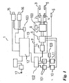
図1を参照すると、監視サイトに設置された監視システム1が示されている。この監視システムは、上方位置センサ2、3と、側面位置センサ4、5と、機関車センサ6とを備えている。これらのセンサから出る信号は、パンタグラフが監視ステーションにあるとき、センサインターフェイス7によって受信される。センサインターフェイス7は、センサ信号調節器8と、インターフェイス回路9とを有している。監視ステーションに機関車が存在することを示す信号と、監視ステーションにパンタグラフが存在することを示す信号とを同時に受信すると、インターフェイス回路9は、これらの信号を2つのストリームへと分割する。第一のストリームは、監視サイトで機関車の通し番号を取得するAVIタグリーダ10、11を駆動させる。タグリーダ10、11から受信されたデータは、変換器101(たとえば、RS−422からUSBへ)によってUSBフォーマットに変換され、USBハブ102を通り、コンピュータ13上で駆動しているステーション管理システム12へと進む。ここに、データが格納される。第二のストリームは、USB変換器14へのディジタルI/Oによって処理され、システム12によって受信され、次いで、イメージキャプチャデバイス15、16の動作をトリガーする。次に、イメージキャプチャデバイス15、16によって取得されたイメージは、ステーション管理システム12によって受信され、このステーション管理システム12は、取得されたイメージを解析し、パンタグラフが損傷しているか否かおよび/または構成部品である炭素集電装置が摩耗しているか否かを評価する。パンタグラフの損傷および摩耗の解析結果への遠隔の位置からのアクセスは、コンピュータ13をコンピュータネットワークに接続する接続部17によって促進される。AVIタグリーダ10、11、センサ信号調節器8、イメージキャプチャデバイス15、16は、電源103(たとえば、24V DC)に接続されている。
Referring to FIG. 1, a monitoring system 1 installed at a monitoring site is shown. This monitoring system includes
いうまでもなく、パンタグラフを有した機関車は、正常なサービスに従事しているとき、すなわち、機関車が、監視サイトを有している主線、支線またはサービス線を移動し、典型的には12kph以上かつ80kph以下の速度で移動しているとき、監視システム1によって評価される。 Needless to say, a locomotive with a pantograph is typically engaged in normal service, i.e., the locomotive moves on a main line, branch line or service line with a monitoring site, typically It is evaluated by the monitoring system 1 when moving at a speed of 12 kph or more and 80 kph or less.
コンピュータ13は、CPUによって実行可能なプログラムのインストラクションを有体的に具象化しかつマシンによって可読なデータ格納デバイスと通信する中央処理装置(CPU)を有している。これらの格納デバイスには、RAM、ROM、磁気、光ディスク、ディスクドライブなどの如き第二の格納デバイスが含まれている。これらの格納デバイスのうちの一または複数は、本発明の実施形態にかかる方法を具象化するために、CPUにより実行されるインストラクションを有している。通常、これらのインストラクションは、メモリ集積回路によりまたは遠隔サーバ装置からコンピュータネットワークを介して提供されてもよいが、光ディスクの如きインストレーションディスクから搭載されるようになっている。これらのインストラクションは、ソフトウェア製品を構成しており、実行されると、コンピュータシステム13をパンタグラフ損傷および/または摩耗検出システムとして駆動させ、かつ、とくに複数のフロー図を参照して下記に記載される方法を実行させるようになっている。
The
当業者にとって明らかなように、本発明の方法から考えると、ソフトウェア製品のプログラミングは簡単である。その好ましい実施形態を記載する。下記の方法では、さまざまな変数およびデータが操作される。明らかなように、本発明の方法を実装すべくコンピュータシステムを動作中、電気信号がコンピュータシステムの伝導バスに沿って移動し、CPUの対応するレジスタの値が増加し、第二の格納デバイスおよびRAMに、データが書き込まれ、第二の格納デバイスおよびRAMからデータが検索される。したがって、ソフトウェアを実行して本発明の実施形態にかかる方法を実施すると、コンピュータシステム内に物理的な影響および変化が生じることになる。 As will be apparent to those skilled in the art, in view of the method of the present invention, programming a software product is straightforward. The preferred embodiment will be described. In the method described below, various variables and data are manipulated. As will be apparent, while operating the computer system to implement the method of the present invention, electrical signals move along the computer system conduction bus, the corresponding register value of the CPU increases, the second storage device and Data is written to the RAM, and the data is retrieved from the second storage device and RAM. Therefore, executing software to perform the method according to embodiments of the present invention will cause physical effects and changes in the computer system.
図2を参照すると、駆動後の側面位置イメージキャプチャデバイスから得られる視界が示されている。架空線21に接する2つの炭素集電装置19、20を有するY字形バーパンタグラフ18が示されている。また、接触した線の上方に吊されている懸垂線22も示されている。これらの集電装置は白色のバックスクリーン23を背景にして示されている。また、図2には、各炭素集電装置19、20が炭素支持体24と炭素ブロック25とを有していることをさらに明白に示されている。
Referring to FIG. 2, the field of view obtained from the side position image capture device after driving is shown. A Y-shaped
図3を参照すると、駆動後の、上方位置イメージキャプチャデバイスから得られる視界が示されている。Y字形ホーン26、27を有しているY字形バーパンタグラフが示されている。
Referring to FIG. 3, the field of view obtained from the upper position image capture device after driving is shown. A Y-shaped bar pantograph having Y-shaped
図4を参照すると、センサインターフェイスタイミング図が示されている。このセンサインターフェイスタイミング図には、センサインターフェイス7により受信される機関車センサ6、上方位置パンタグラフセンサ2、3および側面位置パンタグラフセンサ4,5から出力される出力信号28、29、30が示されている。明らかなように、線は時間の関数としての出力信号値を表わしている。長さが約17mである機関車が機関車センサによって検出されると、高い出力信号が相当な期間にわたってセンサインターフェイスによって受信される。センサインターフェイスが機関車センサからの高出力信号28およびパンタグラフ信号29、30を同時に受信すると、センサインターフェイス7は、ステーション管理システム11を介して指令信号31、32をイメージキャプチャデバイス15、16に向けてトリガーする。機関車センサ28からならびに上方位置パンタグラフセンサ29および側面位置パンタグラフセンサ30から高い出力信号を同時に受信すると、機関車通し番号を取得するための命令33、34がAVIタグリーダ10、11に向けてトリガーされる。
Referring to FIG. 4, a sensor interface timing diagram is shown. In this sensor interface timing diagram, output signals 28, 29, 30 output from the locomotive sensor 6, the upper
図5を参照すると、スイッチマトリクス35と、コンピュータ13(図示せず)のシリアルポートへ接続されるUSB変換器14へのディジタルI/Oと、AVIタグリーダ9、10を制御するドライバ36、37とを有したセンサインターフェイス7の図が示されている。スイッチマトリクス35は、パンタグラフセンサ2〜5および機関車センサ6からバウンス(ノイズ)が除去されかつパルス波形を有した信号を受信する。これらのセンサから高い出力信号を同時に受信すると、スイッチマトリクスが命令38、39を供給し、これらの命令がASCII文字のストリームに変換されてシリアルポートを介してコンピュータ13へ転送される。また、スイッチマトリクス35がAVIタグリーダドライバ36、37にも命令に40、41を送信する。
Referring to FIG. 5, a
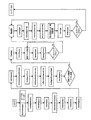
図6を参照すると、パンタグラフの炭素集電装置が摩耗しているか否かを解析するためのステーション管理プログラムのセグメントを表わすフロー図が示されている。このセグメントは以後PanCamと呼ぶこととする。高解像度ビデオカメラによって、監視サイトにおいてパンタグラフの側面視のイメージが取得される。次いで、このカメラによって取得されたイメージデータがプログラムによって解析される。プログラムは、イメージデータを変える複数のサブルーチンを呼び出す。PanCamには、MVTec Software GmbHによって販売されているHALCONマシンビジョンライブラリが用いられている。これらのサブルーチンは、通常PanCamによって次の順番で呼び出される。 Referring to FIG. 6, a flow diagram representing a segment of the station management program for analyzing whether a pantograph carbon current collector is worn or not is shown. This segment is hereinafter referred to as PanCam. A high resolution video camera captures a side view image of the pantograph at the surveillance site. Next, the image data acquired by this camera is analyzed by the program. The program calls a plurality of subroutines that change the image data. PanCam uses the HALCON machine vision library sold by MVTec Software GmbH. These subroutines are usually called in the following order by PanCam.
EquHistoImage()が、強度ヒストグラム内の値の分布がすべての値の間でほぼ等しくなるように、入力イメージを修正する。PanCamは、この結果を出力イメージとして用いる。その理由は、通常、この結果が人による閲覧に適した良好なコントラスト特性を有しているからである。 EquHistoImage () modifies the input image so that the distribution of values in the intensity histogram is approximately equal among all values. PanCam uses this result as the output image. This is because the result usually has good contrast characteristics suitable for human viewing.
Copylmage()が呼び出される。これは、入力イメージをコピーし、(カメラによって出力される元の12ビットから)8ビットにその色深度を下げる。その理由は、HALCONオペレータ(とくに、パターンマッチング)が8ビットの深度のイメージしか受け入れないからである。 Copyimage () is called. This copies the input image and reduces its color depth to 8 bits (from the original 12 bits output by the camera). The reason is that the HALCON operator (especially pattern matching) accepts only 8 bit depth images.
次いで、プログラムは、FindShapeModel()を呼び出し、バックボードの前もって定められたモデルとイメージとをマッチングさせる。マッチングされたモデルの座標とPanCamが予測するバックボードの位置の座標とを比較することにより、PanCamは、座標オフセットを計算し、後の処理において対象となる固定された領域の調整を行うことができる。これらの調整は、保守作業または他の変動によって引き起こされるカメラ視角の移動により必要となる場合がある。 The program then calls FindShapeModel () to match the pre-determined model and image on the backboard. By comparing the coordinates of the matched model and the coordinates of the backboard position predicted by PanCam, PanCam can calculate the coordinate offset and adjust the fixed area of interest in later processing. it can. These adjustments may be necessary due to camera viewing angle movements caused by maintenance operations or other variations.
背景座標調整オフセットを用いて、プログラムは、MoveRegion()を呼び出し、対象となるバックボード領域を調整する。次いで、GrayHisto()が呼び出され、対象となる領域上の強度ヒストグラムが計算される。 Using the background coordinate adjustment offset, the program calls MoveRegion () to adjust the target backboard area. Next, GrayHisto () is called to calculate an intensity histogram over the region of interest.
この時点で、目標は、バックボードからパンタグラフのプロフィール(Profile)を抽出することができるように、2ビットのセグメンテーションにおけるしきい値として用いるのに適切な強度値を検出することにある。PanCamは、サーチからヒストグラムの上端部および下端部のうちある一定のパーセンテージを除外することによりセグメンテーションに用いられる最小強度値または最大強度値の誤った選択を回避し、次いで、SmoothFunctldGauss()を呼び出し、先を切り取られたヒストグラムに対してガウス平滑化(Gaussian Smoothing)を行なう。 At this point, the goal is to find an appropriate intensity value to use as a threshold in a 2-bit segmentation so that a pantograph profile can be extracted from the backboard. PanCam avoids erroneous selection of the minimum or maximum intensity values used for segmentation by excluding certain percentages of the top and bottom edges of the histogram from the search, then calls SmoothFuncldGauss (), Gaussian smoothing is performed on the histogram that has been cut off.
GetYValueFunctld()は、平滑化されたヒストグラム内に極小値を検出し、これらの極小値を中心とする「ウィンドウ」を繰り返し拡大し、ウィンドウ高の平方に対するウィンドウ幅の比を最大限に大きくする。ここで、高さはウィンドウ内の最大ヒストグラムビンカウントであり、幅はピクセル値の範囲である。選択されるウィンドウは、先を切られたヒストグラム内のこのようなウィンドウ全てのうちの最も幅広のアスペクト比を有したものである。次いで、PanCamは、初期の8ビットのセグメンテーションしきい値として、このアスペクト比を最大化するウィンドウの中点を選択する。 GetYValueFunction () detects local minima in the smoothed histogram, repeatedly enlarges the “window” around these local minima, and maximizes the ratio of the window width to the square of the window height. Here, the height is the maximum histogram bin count in the window and the width is the range of pixel values. The selected window is the one with the widest aspect ratio of all such windows in the truncated histogram. PanCam then selects the midpoint of the window that maximizes this aspect ratio as the initial 8-bit segmentation threshold.
HALCONでは、ヒストグラムオペレータは、8ビットを超える色深度を有するイメージに対して自動的に0〜255の範囲でマッピングするようになっている。まず、PanCamは、ヒストグラムの作成に用いられるイメージ領域にわたってMinMaxGray()を呼び出し、最小値および最大値を見出さなければならない。次いで、PanCamは、線形変換を用いて、初期の8ビットのしきい値を対応する12ビットのセグメンテーションしきい値にマッピングするに必要な計算を行うことができる。次いで、PanCamは、このしきい値を用いて、パンタグラフのプロフィールのセグメンテーションを行なう。 In HALCON, the histogram operator automatically maps to an image having a color depth exceeding 8 bits in the range of 0-255. First, PanCam must call MinMaxGray () over the image region used to create the histogram to find the minimum and maximum values. PanCam can then use a linear transformation to perform the calculations necessary to map the initial 8-bit threshold to the corresponding 12-bit segmentation threshold. PanCam then uses this threshold to segment the pantograph profile.
ステップ4と同様に、PanCamは、パンタグラフのプロフィールを正確に検査することができる領域を調整する。PanCamは、HALCONを用いて、セグメンテーションされたパンタグラフのプロフィールおよび有効な対象領域に対して領域Intersection()を実行する。 Similar to step 4, PanCam adjusts the area where the pantograph profile can be accurately examined. PanCam uses HALCON to perform a region Intersection () on the segmented pantograph profile and the valid region of interest.
先の場合と同様に、PanCamは、MoveRegion()を用いて、パンタグラフモデルとマッチングさせる検査領域を調整する。PanCamは、AddChannels()およびFindScaledShapeModels()を呼び出し、単一の操作で複数のパンタグラフのマッチングを検索する。最も高いスコアでの合致(match)は、最良の合致を示すので、パンタグラフタイプの最も確からしい識別を示すことになる。 As in the previous case, PanCam uses MoveRegion () to adjust the inspection region to be matched with the pantograph model. PanCam calls AddChannels () and FindScaledShapeModels () to retrieve multiple pantograph matches in a single operation. The match with the highest score indicates the best match and thus the most probable identification of the pantograph type.
HALCONには、ピラミッドマッチングアルゴリズムが用いられており、このアルゴリズムでは、マッチング作業速度を向上させるためにまず低解像度でモデルのマッチングが行われる。このことにより、解像度が低いために誤った合致に帰着する場合もある。そこで、PanCamは、TestRegionPoint()を呼び出し、合致したモデルが一定の検査領域内に確実に位置したものであるか否かをチェックする。誤った合致は無視され、そうでなければ、PanCamは、GetShapeModelContoursQ、AffineTransContourXld()およびGenRegionContourXld()を呼び出し、合致したモデルを出力イメージ上に表示する。 In HALCON, a pyramid matching algorithm is used, and in this algorithm, a model is first matched at a low resolution in order to improve the matching operation speed. This may result in an incorrect match due to the low resolution. Therefore, PanCam calls TestRegionPoint () to check whether the matched model is surely located within a certain inspection area. False matches are ignored, otherwise PanCam calls GetShapeModelControlsQ, AffineTransControlXld () and GenRegionControlXld () to display the matched model on the output image.
PanCamは、いったんパンタグラフを識別してその場所を検出すると、GenRegionPolygonFilledOを呼び出し、基準点としてのパンタグラフモデルの位置とともに一定の座標オフセットを用いて、炭素集電装置が位置すると思われる場所のまわりの領域を出力させる。また、PanCamはこれらの領域を出力イメージ上に表示する。 Once PanCam identifies the pantograph and detects its location, it calls GenRegionPolygonFilledO and uses a certain coordinate offset along with the location of the pantograph model as a reference point to the area around where the carbon current collector is supposed to be located. Is output. PanCam also displays these areas on the output image.
先の場合と同様に、PanCamは、MoveRegion()を用い、イメージ内においてバックボードの上側縁部が位置すると思われる場所を表した予め定められた領域を調整する。炭素集電装置領域がバックボードの上側縁部のうちの過剰部分をオーバーラップしている場合、PanCamは、炭素集電装置が解析結果の信頼性が低い位置にあると判断して、それに対してさらなる処理を行なわない。 As before, PanCam uses MoveRegion () to adjust a predetermined area that represents the location where the upper edge of the backboard is likely to be located in the image. If the carbon current collector area overlaps the excess of the upper edge of the backboard, PanCam determines that the carbon current collector is in a position where the analysis results are unreliable, No further processing.
PanCamは、炭素集電装置領域の画素面積をチェックする。その面積が0である場合、このイメージの中で処理するデータはない。PanCamは、このイメージにさらなる処理を行わず、「パンなし(no pan)」という報告をする。このことは、PanCamが完全にパンタグラフの場所を逃すなどして誤った診断情報を作成しうるようなまれな状況をカバーするようになっている。 PanCam checks the pixel area of the carbon current collector region. If the area is 0, there is no data to process in this image. PanCam reports no further processing on this image and reports “no pan”. This covers a rare situation where PanCam can create erroneous diagnostic information, such as completely missing the location of the pantograph.
PanCamは、損傷および摩耗の有無をチェックする前に、炭素集電装置のプロフィール内の不要なアーチファクト(artifacts)を取り除く必要がある。PanCamは、まずOpening()形態オペレータを用い、イメージ内の架空線のプロフィールを取り除く。その理由は、これらが炭素集電装置のプロフィールの上側縁部と交差するためである。PanCamは、各領域が炭素集電装置のプロフィールの上側縁部の異なる傾斜からなっているために異なる構造用部材を用いて、2つのオーバーラップしていない領域に対してこの動作を行なう。各々の場合において、PanCamは、ステップ4で計算された背景オフセットに応じて、Openingを実行する領域の位置をさらに調整する。 PanCam needs to remove unwanted artifacts in the carbon current collector profile before checking for damage and wear. PanCam first uses the Opening () form operator to remove the overhead line profile in the image. The reason is that they intersect the upper edge of the carbon current collector profile. PanCam performs this operation on two non-overlapping regions using different structural members because each region consists of a different slope of the upper edge of the carbon current collector profile. In each case, PanCam further adjusts the position of the area where Opening is performed according to the background offset calculated in step 4.
PanCamは、SelectShape()を呼び出し、炭素集電装置のうちの一部と考えるには小さすぎ、かつ遠隔の位置にありすぎる部分を取り除くことにより、炭素集電装置のプロフィールのフィルタリングを続ける。バックボード上のダークスポット(所定の時間にわたって蓄積される)により、これらの誤ったプロフィールが生じることが多い。 PanCam calls SelectShape () and continues to filter the carbon current collector profile by removing those parts that are too small to be considered part of the carbon current collector and too remote. Often these false profiles are caused by dark spots on the backboard (which accumulate over time).
PanCamは、鉛直線で、炭素集電装置のプロフィール領域を拡大し、炭素集電装置の上方プロフィールよりも下に位置するすべてを満たす「レインフォール」効果を生じさせることにより、炭素集電装置にステップを検出する。また、PanCamは、元の炭素集電装置のプロフィール上に大きな円領域を用いてClosingを実行する。閉じられた領域からレインフォール領域を差し引くことによって、残った領域は炭素内の「ステップ」損傷を示しうる。 PanCam extends the profile area of the carbon current collector in the vertical line, creating a “rainfall” effect that fills everything below the upper profile of the carbon current collector. Detect steps. PanCam also performs Closing using a large circular area on the original carbon current collector profile. By subtracting the rainfall region from the closed region, the remaining region can exhibit “step” damage in the carbon.
PanCamは、パンタグラフホーンの近傍に認識不能な形状を残しうるレインフォール動作からのアーチファクトを取り除くために、直前のステップで計算された結果領域を制限する必要がある。さらに先の場合と同様に、PanCamは、背景オフセットに応じて固定された対象領域を調整し、次いで、有効領域および前のステップの結果に対してIntersection()を呼び出す。 PanCam needs to limit the result area calculated in the previous step to remove artifacts from the rainfall motion that can leave an unrecognizable shape in the vicinity of the pantograph horn. As before, PanCam adjusts the fixed region of interest according to the background offset, and then calls Intersection () for the effective region and the result of the previous step.
損傷解析の最終部分では、PanCamは、小さな半径を備えたOpeningCircle()を呼び出し、前のステップの結果から小さなアーチファクトを取り除く。次いで、その結果内の不連続領域が一定のしきい値より大きな面積を有している場合、PanCamは炭素集電装置にステップ損傷が存在する可能性が存在すると考える。この場合、(強調された損傷を明瞭にさせておくために)、PanCamは、損傷領域を拡大して輪郭を出力することによって、出力イメージにその結果をさらに表示する。 In the final part of the damage analysis, PanCam calls OpeningCycle () with a small radius and removes small artifacts from the results of the previous step. If the discontinuous region in the result then has an area greater than a certain threshold, PanCam considers that there is a possibility of step damage in the carbon current collector. In this case (to keep the highlighted damage clear), PanCam further displays the result in the output image by enlarging the damaged area and outputting a contour.
ステップ16〜18は、パンタグラフが「Y」タイプであれば、第二の炭素集電装置に対して繰り返される。明らかなように、T字形バーパンタグラフを表わすモデルに合致した入力イメージからは1つの炭素集電装置のプロフィールイメージしか抽出されない。その理由は、遠い炭素集電装置のプロフィールがパンタグラフ内の水平棒により不明瞭になるからである。 Steps 16-18 are repeated for the second carbon current collector if the pantograph is of type “Y”. As is apparent, only one carbon current collector profile image is extracted from the input image that matches the model representing the T-shaped bar pantograph. The reason is that the distant carbon current collector profile is obscured by the horizontal bars in the pantograph.
摩耗解析については、PanCamは、架空線および他のアーチファクトを取り除くための処理が既になされている炭素集電装置のプロフィールを用いる。そのプロフィールに1を超える不連続領域がある場合、PanCamは、そのプロフィールを廃棄し、第二の炭素集電装置へと移動する。 For wear analysis, PanCam uses a carbon current collector profile that has already been processed to remove overhead wires and other artifacts. If there is more than one discontinuous region in the profile, PanCam discards the profile and moves to a second carbon current collector.
PanCamは、遠近法の縮尺によって炭素集電装置がどの程度影響を受けるかを判断しなければならない。その理由は、異なるイメージにおいて、パンタグラフがカメラに対してさまざまな位置にありうるからである。PanCamsでは、頭上の電力ケーブルを見つけるためにLinesGauss()というライン発見オペレータが用いられる。次いで、PanCamは、満足な程度に真っ直ぐな線(曲線またはアーク状の線と比較して)のみを選択するためのSelectShapeXldQと、架空線と同一の方向に走ると考えられる線を選択するためのSelectContoursXld()とを呼び出す。次いで、PanCamは、FitLineContourXldOを呼び出し、その他の線の直線式を(Tukeyアプローチを用いて)計算し、その結果と炭素集電装置の上側縁部との間の交点を取得する。PanCamは、遠近法の縮尺の調整のための基準点としてこの交点を用いる。 PanCam must determine how much the carbon current collector is affected by the perspective scale. The reason is that the pantograph can be in various positions with respect to the camera in different images. In PanCams, a line discovery operator called LineGauss () is used to find overhead power cables. PanCam then selects SelectShapeXldQ to select only lines that are straight enough (compared to curved or arcuate lines) and lines that are considered to run in the same direction as the overhead lines. Call SelectControlsXld (). PanCam then calls FitLineControlXldO and calculates the linear expression of the other lines (using the Tukey approach) to get the intersection between the result and the upper edge of the carbon current collector. PanCam uses this intersection as a reference point for adjusting the perspective scale.
前のステップで計算された基準点を用いて、PanCamは、予め定められた一定の式にカラム座標を適用し、炭素高さ最小しきい値に対する調整係数を計算する。カメラに接近するにつれておよびパンタグラフの遠近法の縮尺に対応して、カメラにより近い炭素集電装置は、カメラからより遠い炭素集電装置よりも炭素高さしきい値が大きくなる。 Using the reference points calculated in the previous step, PanCam applies column coordinates to a predetermined constant formula to calculate an adjustment factor for the minimum carbon height threshold. As the camera is approached and corresponding to the pantograph perspective scale, the carbon current collector closer to the camera has a higher carbon height threshold than the carbon current collector farther from the camera.
PanCamが、いったん最小受け入れ高さを決定すると、構造エレメントとして、その高さの鉛直線を備えたOpening()オペレータを用いる。次いで、PanCamは、Difference()を呼び出し、元の炭素集電装置のプロフィールからopeningの結果を差し引く。残っている領域が過剰な炭素摩耗の可能性を示しており、PanCamは、その残りのイメージ領域の幅が十分に大きい場合、摩耗しているものとして炭素集電装置にフラグを立てる。この場合、PanCamは、出力イメージ上の摩耗領域を、当該領域を拡大してその輪郭を表示することにより強調する。 Once PanCam determines the minimum accepted height, it uses the Opening () operator with a vertical line at that height as the structural element. PanCam then calls Difference () and subtracts the opening result from the original carbon current collector profile. The remaining area indicates the possibility of excessive carbon wear, and PanCam flags the carbon current collector as worn if the width of the remaining image area is sufficiently large. In this case, PanCam emphasizes the wear area on the output image by enlarging the area and displaying its outline.
パンタグラフが「Y」タイプである場合、ステップ20〜23が第二の炭素集電装置に対して繰り返される。明らかなように、入力イメージ内のパンタグラフがT字形バーパンタグラフを表わすモデルと合致する場合、ステップ20〜23は繰り返されない。その理由は、遠い炭素集電装置のプロフィールがパンタグラフ内の水平棒により不明瞭になるからである。 If the pantograph is of the “Y” type, steps 20-23 are repeated for the second carbon current collector. As will be apparent, if the pantograph in the input image matches the model representing the T-shaped bar pantograph, steps 20-23 are not repeated. The reason is that the distant carbon current collector profile is obscured by the horizontal bars in the pantograph.
図7を参照すると、監視サイトにおけるパンタグラフの構成要素となるホーンが損傷しているか否かを判断するプログラムを表わすフロー図が示されている。監視サイトにおいてパンタグラフの上方から遠近法を用いて見たイメージが高解像度ビデオカメラにより取り込まれる。次いで、このカメラにより取り込まれたイメージデータはプログラムにより解析される。このプログラムは、イメージデータを変化させる複数のサブルーチンを呼ぶ。これらのサブルーチンは、プログラムにより次の順番で通常呼び出される。 Referring to FIG. 7, there is shown a flowchart representing a program for determining whether or not a horn which is a component of a pantograph at a monitoring site is damaged. An image viewed using a perspective method from above the pantograph at a monitoring site is captured by a high-resolution video camera. Next, the image data captured by the camera is analyzed by a program. This program calls a plurality of subroutines that change the image data. These subroutines are normally called by the program in the following order.
EquHistoImage()は、入力イメージの強度ヒストグラム内の値の分布がすべての値の間でほぼ等しくなるように入力イメージを修正する。PanCamは、この結果が人による閲覧に適した良好なコントラスト特性を通常有しているため、この結果を出力イメージとして用いる。 EquHistoImage () modifies the input image so that the distribution of values in the input image's intensity histogram is approximately equal among all values. PanCam uses this result as an output image because it usually has good contrast characteristics suitable for human viewing.
CopylmageOが、呼び出され、入力イメージをコピーするものの、その色深度をカメラにより作成された元の12ビットから8ビットに下げる。その理由は、HALCONオペレータ(とくに、パターンマッチング)が8ビットの深度のイメージしか受け入れないからである。 CopyimageO is called to copy the input image, but lowers its color depth from the original 12 bits created by the camera to 8 bits. The reason is that the HALCON operator (especially pattern matching) accepts only 8 bit depth images.
パンタグラフを検査する前に、PanCamは、まずそのイメージに対して予め定められた線路モデルとのマッチングを試みる。HALCONがそのイメージ内に一組の線路を検出することに成功できた場合、PanCamはイメージの中に機関車が実際に存在しないと仮定する。その理由は、機関車が存在すればこれらの線路が視界をさえぎられるからである。この場合、PanCamは、現在の画像を拒絶し、次のものに移動して処理用する。 Before inspecting the pantograph, PanCam first tries to match the image with a predetermined line model. If HALCON can successfully detect a set of tracks in the image, PanCam assumes that no locomotive is actually present in the image. The reason is that if a locomotive is present, these tracks can be blocked from view. In this case, PanCam rejects the current image and moves to the next one for processing.
PanCamは、ReduceDomain()を呼び出し、イメージ内のパンタグラフの合致が期待される予め定められた領域に検査領域を絞る。次いで、それは、FindScaledShapeModels()を呼び出し、複数の予め定められたパンタグラフモデルに対してマッチングを行う。側面視処理におけるパターンマッチングと同様に、PanCamは、TestRegionPoint()オペレータを用いて、誤った合致をチェックしなければならない。このチェックが失敗した場合、パンタグラフの合致が、予測されたパンタグラフ領域からあまりにも外側にあるものとして拒絶される。PanCamは、パターンマッチングから戻された縮尺係数を、以後のマッチング動作でのオフセットの縮尺係数として用い、遠近法の縮尺に対応する。 PanCam calls ReduceDomain () to narrow the inspection area to a predetermined area where pantograph matches in the image are expected. It then calls FindScaledShapeModels () to perform matching on multiple predefined pantograph models. Similar to pattern matching in side view processing, PanCam must check for false matches using the TestRegionPoint () operator. If this check fails, the pantograph match is rejected as being too far from the predicted pantograph region. PanCam uses the scale factor returned from the pattern matching as an offset scale factor in the subsequent matching operation, and corresponds to the perspective scale.
パンタグラフを見つけて識別した後、PanCamは(側面視パターンマッチングと同様に)、GetShapeModelContours()、AffineTransContourXld()およびGenRegionContourXld()を用いて合致したモデルを出力イメージ上に表示する。 After finding and identifying the pantograph, PanCam (similar to side view pattern matching) displays the matched model on the output image using GetShapeModelContours (), AffineTransControlXld () and GenRegionControlXld ().
PanCamは、合致したパンタグラフの座標および一組の予め定められた座標オフセット(ステップ4で求められた縮尺係数に基づいて縮尺される)を用いて、ホーンが探されるパンタグラフの左右に新規の検査領域を算出する。次いで、PanCamは、それぞれの側で一度ずつさらなるパターンマッチング動作を行ない、ホーンの有無をチェックする。 PanCam uses the matched pantograph coordinates and a set of pre-determined coordinate offsets (scaled based on the scale factor determined in step 4) to create a new inspection area to the left and right of the pantograph where the horn is sought. Is calculated. PanCam then performs a further pattern matching operation once on each side to check for the presence of a horn.
Y字形バーパンタグラフについては、マッチング動作にはホーンに対して単一のモデルが用いられる。しかしながら、ホーンが3つの別個の脚部(prong)からなっているT字形バーパンタグラフについては、PanCamは、まず長い中央のホーン部分を探す。次いで、パターンマッチングが成功したと仮定した場合、PanCamは、ホーン部分の位置および一組の縮尺された予め定められた座標オフセットから算出されるさらに二つの検査領域を生じる。次いで、PanCamは、さらに他のパターンマッチング動作を行い、残りの二つのホーン部分の有無をチェックする。 For the Y-shaped barpantograph, a single model for the horn is used for the matching operation. However, for a T-bar pantograph where the horn consists of three separate prongs, PanCam first looks for the long central horn portion. Then, assuming that the pattern matching was successful, PanCam yields two more inspection areas calculated from the position of the horn portion and a set of scaled predetermined coordinate offsets. PanCam then performs another pattern matching operation to check for the presence of the remaining two horn portions.
パターンマッチャが前のステップの任意の段階でホーンまたはホーン部分を見つけられなかった場合、PanCamはホーンが損傷していると宣言する。HALCONがホーンまたはホーン部分のマッチングに成功した場合、PanCamは合致したモデルを出力イメージ上に表示する。 If the pattern matcher fails to find the horn or horn part at any stage of the previous step, PanCam declares that the horn is damaged. If HALCON succeeds in matching the horn or horn part, PanCam displays the matched model on the output image.
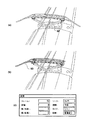
図8aを参照すると、側面視用のイメージキャプチャデバイスから得られた視界が示されている。ここでは、Y字形バータイプパンタグラフ44の一対の炭素集電装置42、43のプロフィールがバックスクリーン45を背景にして示されている。図8bは、直前に記載されたイメージ上に重ね合わされた摩耗および損傷の解析結果を示す合成イメージである。黄色の輪郭46、47は、摩耗について解析された各炭素集電装置のプロフィールの領域を強調している。赤い輪郭48は、「ステップ」損傷の可能性のある領域を強調している。シアン色の輪郭49、50、51は、パンタグラフモデルマッチングの結果を示している。図8cには、解析結果が示されている。
Referring to FIG. 8a, the field of view obtained from an image capture device for side view is shown. Here, the profiles of the pair of carbon
図9aを参照すると、平面視用のイメージキャプチャデバイスから得られた視界が示される。ここでは、Y字形バータイプのパンタグラフ52が示されている。図9bでは、平面視用のイメージキャプチャデバイスから得られた視界が示されている。ここでは、Y字形バータイプのパンタグラフ52が構成要素のホーン53を欠いている。図9cには、グラフィカルユーザインターフェイスにより提示されるようなホーン損傷解析の結果が示されている。
Referring to FIG. 9a, a field of view obtained from an image capture device for planar viewing is shown. Here, a Y-shaped
図10を参照すると、側面視用のイメージキャプチャデバイスから得られる視界が示されている。ここでは、Y字形バータイプパンタグラフの一対の炭素集電装置54,55のプロフィールがバックスクリーン56を背景にして示されている。損傷解析の結果がイメージ上に重ね合わされている。青色の輪郭57、58、59が、過剰な摩耗領域を取り囲んでいる。黄色の輪郭60、61が、各炭素集電装置のプロフィールのうちの摩耗について解析された領域を強調している。赤色の輪郭62、63、64が「ステップ」損傷の可能性のある領域を強調している。シアン色の輪郭65、66、67は、パンタグラフモデルマッチングの結果を示している。
Referring to FIG. 10, a field of view obtained from an image capture device for side view is shown. Here, the profile of a pair of carbon
本発明のとくに好ましいシステムの動作が次のパラグラフに記載されている。 The operation of a particularly preferred system of the present invention is described in the following paragraph.
PanCamプログラム12は多重スレッドアプローチを具象化している。PanCamプログラムは、機関車センサおよびパンタグラフセンサからの信号を扱うスレッドを有している。これらのセンサからの信号を受信すると、それは、イメージキャプチャスレッドにより処理するための待ち行列にセンサ入力を加える。次いで、イメージキャプチャスレッドは、USBI/Oデバイス14により提供される情報に従って、適切なカメラ15、16をトリガーし、イメージを取得する。このイメージが取り入れられると、イメージキャプチャスレッドは、処理を待つイメージの待ち行列にたった今取り入れたイメージを加える。
The
それと同時に、線路の両側に配置されたAVIタグリーダ10、11は機関車識別情報を受信する。これらのタグリーダはこの情報をPanCamを実行しているコンピュータ13へ送信する。この情報はシリアルポートを通じてASCII文字ストリームとして送信される。PanCamソフトウェアは、これを、直前に受信した受信タグを有しているバッファ内に格納する。
At the same time, the
イメージ処理スレッドは、イメージ処理待ち行列から一度に一つずつイメージを取り出し、これらのイメージを解析する。イメージ処理スレッドは、各イメージを車両識別タグと関連付けする。この受信時刻はイメージ取得時間と最も緊密に合致する。イメージ取得の2.5分内(5分のウィンドウ)のタイムスタンプを有したIDタグがない場合、PanCamは、対応するIDタグなしでそのイメージを処理する。 The image processing thread retrieves images one at a time from the image processing queue and analyzes these images. The image processing thread associates each image with a vehicle identification tag. This reception time most closely matches the image acquisition time. If there is no ID tag with a time stamp within 2.5 minutes of image acquisition (5 minute window), PanCam processes the image without a corresponding ID tag.
イメージ処理スレッドは、イメージを解析し、当該イメージを作成したイメージキャプチャデバイスの位置に応じて、炭素集電装置上の損傷もしくは摩耗の兆候の有無またはパンタグラフ上に損傷もしくは紛失したホーンの有無を調べる。解析が完了した後、PanCamは、視覚的なおよびテキストベースの結果をスクリーンに表示することに加えて、ディスク上のイメージファイルおよびテキストファイルに情報を書き込む。診断結果が損傷または摩耗の可能性を示しておりかつユーザがそうするようにPanCamを構成している場合、PanCamは、電子メールおよび/またはSMSを通じてエンドユーザのもとへアラートを送信する。イメージ処理スレッドが電子メール待ち行列に電子メールメッセージを加え、PanCamがこれらの電子メールメッセージを別個の電子メール送信スレッド内で処理する。 The image processing thread analyzes the image and checks for signs of damage or wear on the carbon current collector or for damaged or missing horns on the pantograph, depending on the location of the image capture device that created the image. . After the analysis is complete, PanCam writes information to image and text files on disk in addition to displaying visual and text-based results on the screen. If the diagnostic results indicate a possible damage or wear and the user has configured PanCam to do so, PanCam sends an alert to the end user via email and / or SMS. An image processing thread adds email messages to the email queue, and PanCam processes these email messages in a separate email sending thread.
電子メールでの報告に加えて、PanCamは、標準ODBCインターフェイスを通じて中央データベースサーバに結果を記録するようにしもよい。中央データベースサーバには、データベースとしてマイクロソフトSQLサーバ2005のエクスプレスエディションであるSP2が用いられている。同一のサーバコンピュータ上には、アパッチウェブサーバがPHP5と一緒にセットアップされ、データベースへのウェブアクセスを可能としている。次いで、エンジニア等は、ウェブインターフェイスを介して解析結果を調べ、機関車に必要な調査および修理を行なうことができ、さらに、既に検討した結果をデータベースに記録することもできる。 In addition to e-mail reporting, PanCam may record results to a central database server through a standard ODBC interface. The central database server uses SP2, which is an express edition of Microsoft SQL Server 2005, as a database. On the same server computer, an Apache web server is set up with PHP 5 to allow web access to the database. Then, the engineer or the like can check the analysis result via the web interface, perform the investigation and repair necessary for the locomotive, and can also record the already examined result in the database.
監督されていない環境の下でPanCamの動作の継続を担保するために、PanCamプログラムが内部監視スレッドを有し、この内部監視スレッドがPanCamプログラムの他のスレッドの各々の応答を定期的にチェックするようになっている。これらのスレッドのうちのいずれかが長期間にわたって応答しなくなると、PanCamはコンピュータを再起動する。それに加えて、PanCamプログラムは、それ自体、外部サービスにより監視されている。当該外部サービスは、PanCamを自動的に起動し、PanCamソフトウェアが動作していないまたは応答していないことを検出した場合、PanCamを実行しているコンピュータを再起動させることができる。 In order to ensure that PanCam continues to operate in an unsupervised environment, the PanCam program has an internal monitoring thread that periodically checks the response of each of the other threads in the PanCam program. It is like that. If any of these threads become unresponsive for an extended period of time, PanCam restarts the computer. In addition, the PanCam program is itself monitored by an external service. The external service can automatically start PanCam and restart the computer running PanCam if it detects that the PanCam software is not running or responding.
デスクトップの対話性を担保するシステムアカウントでは、ネットワーク資源へのアクセスはできないようになっている。このことは、マイクロソフトウインドウズシステムの仕組みであり、変更することはできない。PanCamを実行しているコンピュータからイメージおよびデータファイルを中央データベースサーバへのコピーすることを可能とするため、第二のサービスがPanCamプログラムと一緒に実行され代わりにファイルのコピーを実行するようになっている。このコピーサービスは、ウェブサーバファイルシステムへの書き込みを可能とする許可を有しているユーザアカウントの下で実行される。 System accounts that ensure desktop interactivity do not allow access to network resources. This is the mechanism of the Microsoft Windows system and cannot be changed. In order to be able to copy images and data files from the computer running PanCam to the central database server, a second service is run alongside the PanCam program to perform file copying instead. ing. This copy service is run under a user account that has permission to write to the web server file system.
先に記載の実施形態は、本発明の原理の例示のみを意図したものであり、さまざまな修正および変更が当業者にとって明らかである。本発明は、さまざまな方法およびさまざまな実施形態で実行されてもよい。さらに明らかなように、本明細書で用いられている用語は説明を目的としたものであり、限定を目的としたものではない。 The embodiments described above are intended to be illustrative only of the principles of the invention and various modifications and changes will be apparent to those skilled in the art. The present invention may be implemented in various ways and in various embodiments. It will be further appreciated that the terminology used herein is for the purpose of description and is not intended to be limiting.
用語「備える、有するまたは含む」およびその用語の変形体、たとえば「備えている」または「備えた」は、記載された項目または記載された数の項目を内包することを表すために用いられているが、この用語の排他的な解釈が必要な文脈または用途におけるものでない限り、いかなる数の項目を内包することも可能である。 The term “comprising, having or including” and variations of that term, for example “comprising” or “comprising” are used to indicate inclusion of the item or number of items described. However, any number of items can be included, unless the context or application requires an exclusive interpretation of the term.
本明細書に引用された出版物への言及はその開示内容が共通の一般的知識を構成するということを認めているということを意味するものではない。 References to publications cited in this specification are not meant to be an admission that the disclosure constitutes common general knowledge.
Claims (14)
前記パンタグラフの1つのイメージを、前記パンタグラフを有した機関車が正常なサービスに従事している際に取り込む線路側パンタグラフ監視ステーションであって、
前記パンタグラフに対して下方に、かつある傾斜角度で配置されている第一のイメージキャプチャデバイスと、
前記第一のイメージキャプチャデバイスの焦点よりも後側にかつ前記デバイスの視野内に取り付けられているバックスクリーンと、
を有した線路側パンタグラフ監視ステーションと、
前記監視ステーションで取り込まれた前記イメージを解析し、前記パンタグラフの状態を判断するためのステーション管理システムであって、該解析は前記イメージを複数の既知のパンタグラフタイプを表わす複数の予め定められたモデルのうちの1つのモデルとマッチングさせる、ステーション管理システムと、
前記ステーション管理システムを制御し、パンタグラフが損傷および/または摩耗しているか否かを示すためのユーザインターフェイスと、
を備えてなる、システム。 A system for evaluating the state of a pantograph,
A rail-side pantograph monitoring station that captures one image of the pantograph when the locomotive with the pantograph is engaged in normal service,
A first image capture device disposed below the pantograph and at an angle of inclination ;
A back screen mounted behind the focal point of the first image capture device and in the field of view of the device;
A track side pantograph monitoring station with
A station management system for analyzing the image captured at the monitoring station to determine the state of the pantograph, the analysis comprising a plurality of predetermined models representing the image with a plurality of known pantograph types. A station management system that matches one of the models ,
A user interface for controlling the station management system and indicating whether the pantograph is damaged and / or worn;
A system comprising:
データ転送手段と、
機関車が前記監視ステーション内に進入するときに前記機関車を検出するための少なくとも1つの線路側に取り付けられたセンサ(「機関車センサ」)と、
前記監視ステーションにおいて前記パンタグラフの位置を検出するための少なくとも1つの線路側に取り付けられたセンサ(「パンタグラフセンサ」)と、
前記監視ステーションでパンタグラフの少なくとも1つのイメージを取り込む少なくとも1つのイメージキャプチャデバイスと、
これらのセンサから入力を受信し、前記監視ステーションにおいて前記パンタグラフの少なくとも1つのイメージを取り込むように前記少なくとも1つのイメージキャプチャデバイスに命じるセンサインターフェイスと、
を有してなる、請求項1に記載のシステム。 The monitoring station is
Data transfer means;
A sensor ("locomotive sensor") attached to at least one track side for detecting the locomotive when the locomotive enters the monitoring station;
A sensor ("pantograph sensor") attached to at least one line side for detecting the position of the pantograph at the monitoring station;
At least one image capture device for capturing at least one image of a pantograph at the monitoring station;
A sensor interface that receives input from these sensors and directs the at least one image capture device to capture at least one image of the pantograph at the monitoring station;
The system according to claim 1, comprising:
前記監視ステーションは前記パンタグラフの位置を検出する更なるパンタグラフセンサを備えており、該更なるパンタグラフセンサは側面位置パンタグラフセンサであって、該側面位置パンタグラフセンサは前記パンタグラフが前記側面位置イメージキャプチャデバイスの視野内にあるポイントを識別するように位置決めされてなる、請求項11に記載のシステム。 The pantograph sensor is an upper position pantograph sensor, wherein the upper position pantograph sensor is positioned to identify a point at which the pantograph is within the field of view of the upper position image capture device;
The monitoring station includes a further pantograph sensor for detecting the position of the pantograph, the further pantograph sensor being a side position pantograph sensor, wherein the side position pantograph sensor is configured such that the pantograph is at the side position image capture device. The system of claim 11 , wherein the system is positioned to identify a point within the field of view.
センサから少なくとも1つの命令の受信し、該少なくとも1つの命令を受信すると、前記パンタグラフに対して下方にかつある傾斜角度で配置された少なくとも1つのイメージキャプチャデバイスを起動して、監視ステーションにおいて前記パンタグラフの1つのイメージを取り込むステップと、
前記少なくとも1つのイメージキャプチャデバイスにより取り込まれた前記イメージを、損傷および/または摩耗の兆候の有無を調べるために解析するステップであって、該解析は前記イメージを複数の既知のパンタグラフタイプを表わす複数の予め定められたモデルのうちの1つのモデルとマッチングさせるステップを含む、ステップと、
前記解析の結果を出力手段に提供するステップと、
を有している、方法。 A method for analyzing whether a pantograph is damaged and / or worn using a computer program comprising:
Receiving at least one command from the sensor, and upon receiving the at least one command, activates at least one image capture device disposed below and at an angle of inclination with respect to the pantograph, and the pantograph at a monitoring station Capturing one image of
Analyzing the image captured by the at least one image capture device for signs of damage and / or wear, the analysis comprising analyzing the image to represent a plurality of known pantograph types. Matching with one of the predetermined models of:
Providing the result of the analysis to an output means;
Having a method.
監視ステーションにおいて機関車の有無を検出するステップと、
前記監視ステーションにおいてパンタグラフの有無を検出するステップと、
前記監視ステーションにおいて機関車およびパンタグラフを同時に検出すると、前記パンタグラフに対して下方に、かつある傾斜角度で配置されているイメージキャプチャデバイスを駆動させることにより前記パンタグラフのイメージを取り込むステップと、
前記パンタグラフのイメージを解析して前記パンタグラフが損傷しているか否かおよび/または構成部品である炭素集電装置が摩耗しているか否かを判断するステップであって、該解析は前記イメージを複数の既知のパンタグラフタイプを表す複数の予め定められたモデルのうちの1つのモデルとマッチングさせるステップを含む、ステップと、
前記解析の結果をエンドユーザに報告するステップと、
を有している、方法。 A method for automatically determining the state of a pantograph,
Detecting the presence or absence of a locomotive at a monitoring station;
Detecting the presence or absence of a pantograph at the monitoring station;
Capturing simultaneously the locomotive and pantograph at the monitoring station, capturing an image of the pantograph by driving an image capture device disposed below and at an angle of inclination with respect to the pantograph;
The method comprising the pantograph carbon current collector image the pantograph analyzes is whether and / or components are damaged to determine whether worn, the analysis is a plurality of the images including one model the steps of matching of the plurality of predetermined model representing a known pantograph type, comprising the steps,
Reporting the results of the analysis to an end user;
Having a method.
Applications Claiming Priority (3)
| Application Number | Priority Date | Filing Date | Title |
|---|---|---|---|
| AU2007904219A AU2007904219A0 (en) | 2007-08-06 | Pantograph Damage and Wear Monitoring System | |
| AU2007904219 | 2007-08-06 | ||
| PCT/AU2008/001135 WO2009018612A1 (en) | 2007-08-06 | 2008-08-06 | Pantograph damage and wear monitoring system |
Publications (3)
| Publication Number | Publication Date |
|---|---|
| JP2010535658A JP2010535658A (en) | 2010-11-25 |
| JP2010535658A5 JP2010535658A5 (en) | 2011-05-06 |
| JP5659013B2 true JP5659013B2 (en) | 2015-01-28 |
Family
ID=40340879
Family Applications (1)
| Application Number | Title | Priority Date | Filing Date |
|---|---|---|---|
| JP2010519308A Expired - Fee Related JP5659013B2 (en) | 2007-08-06 | 2008-08-06 | System for monitoring pantograph damage and wear |
Country Status (8)
| Country | Link |
|---|---|
| US (1) | US9061594B2 (en) |
| EP (1) | EP2174117B1 (en) |
| JP (1) | JP5659013B2 (en) |
| CN (2) | CN101784887A (en) |
| AU (1) | AU2008286243B2 (en) |
| NZ (1) | NZ582938A (en) |
| WO (1) | WO2009018612A1 (en) |
| ZA (1) | ZA201000639B (en) |
Families Citing this family (65)
| Publication number | Priority date | Publication date | Assignee | Title |
|---|---|---|---|---|
| US20100253329A1 (en) * | 2009-04-07 | 2010-10-07 | Gianni Arcaini | System and Apparatus for Automated Inspection of Overhead Electrical Traction Rail Car Pantographs |
| DE102009043215A1 (en) * | 2009-09-28 | 2011-05-19 | Siemens Aktiengesellschaft | Method and arrangement for controlling pantographs, clearance profiles and horizontal and vertical contact wire position on vehicle bodies |
| JP2012015698A (en) * | 2010-06-30 | 2012-01-19 | Meidensha Corp | Pantograph detection device and method thereof |
| IT1401952B1 (en) * | 2010-09-22 | 2013-08-28 | Henesis S R L | SYSTEM AND METHOD FOR PANTOGRAPH MONITORING. |
| CN102288614B (en) * | 2011-05-19 | 2012-11-07 | 西南交通大学 | Method for detecting pantograph crack fault based on curvelet domain moving parallel window |
| ES2394902B2 (en) * | 2011-06-20 | 2014-05-09 | Universidade De Vigo | SYSTEM AND PROCEDURE FOR MEASURING THE THICKNESS OF PANTOGRAPH FROTERS. |
| CN102255956A (en) * | 2011-06-24 | 2011-11-23 | 广西大学 | Wireless-based pantograph state monitoring system |
| CN102507601B (en) * | 2011-11-08 | 2013-05-15 | 南京大学 | Online abrasion detection method and system for pantograph of electric locomotive |
| US9637005B2 (en) * | 2012-03-30 | 2017-05-02 | Caterpillar Inc. | Display conveying trolley position to operator |
| DE102012217791A1 (en) * | 2012-09-28 | 2014-04-03 | Siemens Aktiengesellschaft | Method for determining a contact wire arrangement and trolley-bound vehicle |
| KR101379325B1 (en) | 2012-10-30 | 2014-03-31 | 한국철도기술연구원 | Caliblator of arc light detector between contact wire and pantograph |
| JP5534058B1 (en) * | 2013-02-19 | 2014-06-25 | 株式会社明電舎 | Wear measuring apparatus and method |
| DE102013207271A1 (en) * | 2013-04-22 | 2014-10-23 | Schunk Bahn- Und Industrietechnik Gmbh | Sanding strip, wear detection system and method for wear detection |
| CN103837087B (en) * | 2013-06-04 | 2016-12-28 | 中国科学院遥感与数字地球研究所 | Pantograph automatic testing method based on active shape model |
| DE102013214022A1 (en) * | 2013-07-17 | 2015-01-22 | Siemens Aktiengesellschaft | System for detecting the condition of a pantograph |
| JP2015068676A (en) * | 2013-09-27 | 2015-04-13 | 株式会社日立ハイテクファインシステムズ | Slider measuring apparatus and slider measuring method |
| WO2016018243A1 (en) * | 2014-07-29 | 2016-02-04 | Hewlett Packard Development Company, L.P. | Default calibrated sensor module settings |
| AU2015318820B2 (en) * | 2014-09-15 | 2020-08-27 | Dti Group Limited | Identification of a pantograph represented in an image |
| CN104833386A (en) * | 2015-04-03 | 2015-08-12 | 苏州华兴致远电子科技有限公司 | Pantograph catenary system monitoring method and system |
| CN105158257B (en) * | 2015-05-21 | 2018-07-20 | 苏州华兴致远电子科技有限公司 | Slide plate measurement method and device |
| FR3038269B1 (en) * | 2015-06-30 | 2017-08-25 | Mersen France Amiens Sas | MONITORING THE STATE OF A CURRENT TRANSMISSION STRIP INTENDED TO FRACTURE AGAINST CATENARY WIRE. |
| DE102015215174A1 (en) * | 2015-08-07 | 2017-02-09 | Siemens Aktiengesellschaft | Device and a method for the overhead operation of a rail vehicle |
| JP6619616B2 (en) * | 2015-11-02 | 2019-12-11 | 東海旅客鉄道株式会社 | Current collector |
| CN105539206B (en) * | 2015-12-24 | 2017-10-17 | 湖南华宏铁路高新科技开发有限公司 | A kind of acquisition methods of electrification railway contact net bar position information |
| CN105571508B (en) * | 2016-01-25 | 2018-03-30 | 成都国铁电气设备有限公司 | The deformation detecting method and system of OCS and pantograph |
| CN105652154B (en) * | 2016-01-25 | 2018-05-11 | 成都国铁电气设备有限公司 | Contact Running State security auditing system |
| FR3047451B1 (en) * | 2016-02-09 | 2019-03-22 | Sncf Reseau | METHOD, DEVICE AND SYSTEM FOR DETECTING THE DEFECT (S) OF A PANTOGRAPH OF A VEHICLE MOVING ON A RAILWAY |
| DE102016205012A1 (en) * | 2016-03-24 | 2017-09-28 | Schunk Bahn- Und Industrietechnik Gmbh | Positioning unit and method of contacting |
| US10807621B2 (en) * | 2017-01-23 | 2020-10-20 | Broadsens Corp. | Train pantograph structural health monitoring system |
| CN107167098A (en) * | 2017-04-21 | 2017-09-15 | 南京理工大学 | Municipal rail train pantograph on-line measuring device and method |
| CN109318717A (en) * | 2017-07-31 | 2019-02-12 | 天津市松正电动汽车技术股份有限公司 | A kind of double source trolleybus image recognition control system and method |
| CN107554303B (en) * | 2017-09-13 | 2023-11-03 | 大同新成新材料股份有限公司 | Device for monitoring carbon sliding plate loss of pantograph in real time |
| CN108225181B (en) * | 2018-01-04 | 2024-04-05 | 武昌首义学院 | Pantograph detection device and method based on laser triangulation method |
| CN110095057A (en) * | 2018-01-31 | 2019-08-06 | 株洲中车时代电气股份有限公司 | A kind of train pantograph method for detecting position, device, excessive phase method and system |
| CN108918550B (en) * | 2018-06-28 | 2021-01-15 | 大同新成新材料股份有限公司 | Pantograph bowing defect detection method |
| DE102018211175A1 (en) * | 2018-07-06 | 2020-01-09 | Aktiebolaget Skf | Monitoring device of an electrical rail system and / or a customer of the rail system |
| JP6995710B2 (en) * | 2018-07-10 | 2022-01-17 | 株式会社日立製作所 | Pantograph arc monitoring system and method |
| CN109101887B (en) * | 2018-07-12 | 2022-03-15 | 中冶北方(大连)工程技术有限公司 | Rail locomotive control method based on visual analysis |
| US11199523B2 (en) * | 2018-09-10 | 2021-12-14 | Pishro Ebtekar Danesh Company (Ped.Co) | System and method for pantograph fault monitoring |
| CN109584296A (en) * | 2018-09-28 | 2019-04-05 | 上海神添实业有限公司 | A kind of fork truck identification distance measuring method based on monocular vision |
| CN109345532A (en) * | 2018-10-11 | 2019-02-15 | 大同新成新材料股份有限公司 | A kind of detection method and detection device of pantograph pan |
| CN109598054A (en) * | 2018-11-29 | 2019-04-09 | 台州智必安科技有限责任公司 | The block of bow collector of electric locomotive and electric arc rapid detection method that can be realized in development board |
| CA3072636A1 (en) | 2019-02-14 | 2020-08-14 | Norfolk Southern Corporation | Edge weather abatement using hyperlocal weather and train activity inputs |
| CN110197494B (en) * | 2019-05-17 | 2023-01-31 | 武汉工程大学 | Pantograph contact point real-time detection algorithm based on monocular infrared image |
| CN110763681B (en) * | 2019-08-23 | 2022-06-10 | 南京理工大学 | Pantograph abrasion area positioning detection method |
| EP4025452A1 (en) * | 2019-09-03 | 2022-07-13 | Schweizerische Bundesbahnen SBB | Device and method for detecting wear and/or damage on a pantograph |
| CN110896447B (en) * | 2019-10-09 | 2020-12-01 | 六安荣耀创新智能科技有限公司 | Instant detection platform for content difference of communication signals |
| CN110910443B (en) * | 2019-12-04 | 2023-03-21 | 成都唐源电气股份有限公司 | Contact net geometric parameter real-time measuring method and device based on single monitoring camera |
| CN113049595A (en) * | 2019-12-27 | 2021-06-29 | 苏州华兴致远电子科技有限公司 | Pantograph wear measurement method and system |
| CN111640155B (en) * | 2020-05-26 | 2023-07-18 | 成都唐源电气股份有限公司 | Pantograph head inclination angle measurement method and system based on 3D imaging |
| CN111609813B (en) * | 2020-05-26 | 2021-11-09 | 成都唐源电气股份有限公司 | Pantograph abrasion measurement method and system based on 3D imaging |
| US11468551B1 (en) | 2020-07-24 | 2022-10-11 | Norfolk Southern Corporation | Machine-learning framework for detecting defects or conditions of railcar systems |
| US11507779B1 (en) | 2020-07-24 | 2022-11-22 | Norfolk Southern Corporation | Two-stage deep learning framework for detecting the condition of rail car coupler systems |
| CN112346395B (en) * | 2020-10-15 | 2022-03-01 | 中车青岛四方机车车辆股份有限公司 | Pantograph slide plate abrasion intelligent control system and method |
| CN112325781B (en) * | 2020-10-16 | 2022-05-17 | 易思维(杭州)科技有限公司 | Rail transit contact line abrasion detection device and method |
| CN112356878B (en) * | 2020-11-19 | 2022-05-17 | 易思维(杭州)科技有限公司 | High-precision detection system for coming and going |
| CN112781492B (en) * | 2020-12-25 | 2022-10-04 | 江苏集萃智能光电系统研究所有限公司 | Multi-binocular-based train pantograph slide plate abrasion online detection equipment and method |
| CN112798598A (en) * | 2021-02-07 | 2021-05-14 | 北京航天计量测试技术研究所 | Contact line abrasion loss detection system and method |
| US20220315074A1 (en) * | 2021-04-02 | 2022-10-06 | Transportation Ip Holdings, Llc | Vehicle control system |
| DE102021208395A1 (en) * | 2021-08-03 | 2023-02-09 | Siemens Mobility GmbH | System for detecting a state of wear of a pantograph, pantograph with such a system, and traction vehicle with such a pantograph |
| US11610484B1 (en) * | 2021-11-30 | 2023-03-21 | Caterpillar Inc. | Control system for maintaining alignment of machine on a trolley assist |
| US11874314B2 (en) * | 2022-02-09 | 2024-01-16 | Caterpillar Inc. | Electrical contact wear monitoring system |
| CN116400623B (en) * | 2023-04-06 | 2024-05-14 | 国网安徽省电力有限公司芜湖供电公司 | Intelligent monitoring system for high-voltage equipment |
| CN116663940B (en) * | 2023-08-01 | 2023-10-20 | 安徽博诺思信息科技有限公司 | Substation safety tool management system and management method |
| CN117876368A (en) * | 2024-03-11 | 2024-04-12 | 成都唐源电气股份有限公司 | Method and system for detecting abrasion and crack of carbon slide plate of contact rail collector shoe |
Family Cites Families (18)
| Publication number | Priority date | Publication date | Assignee | Title |
|---|---|---|---|---|
| US4264927A (en) * | 1979-05-30 | 1981-04-28 | American District Telegraph Company | Freight car identification method |
| JPH05292601A (en) * | 1992-04-02 | 1993-11-05 | Hitachi Electron Eng Co Ltd | Deformation measuring system for pantograph |
| JPH0879904A (en) | 1994-08-31 | 1996-03-22 | Mitsubishi Heavy Ind Ltd | Abnormality detector for pantograph |
| JPH08168102A (en) * | 1994-12-08 | 1996-06-25 | Toshiba Corp | Pantagraph and inspection device thereof |
| JPH08228338A (en) * | 1995-02-22 | 1996-09-03 | Mitsubishi Electric Corp | Device and method for state monitoring |
| JP4209525B2 (en) * | 1998-12-17 | 2009-01-14 | 三菱電機株式会社 | Method for measuring the thickness of pantograph strips |
| JP3403385B2 (en) * | 2000-11-14 | 2003-05-06 | 近畿日本鉄道株式会社 | Pantograph monitoring device |
| GB0229432D0 (en) * | 2002-12-18 | 2003-01-22 | Flux Solutions Ltd | Image display system |
| KR100506085B1 (en) * | 2002-12-28 | 2005-08-05 | 삼성전자주식회사 | Apparatus for processing tongue image and health care service apparatus using tongue image |
| US7068815B2 (en) * | 2003-06-13 | 2006-06-27 | Sarnoff Corporation | Method and apparatus for ground detection and removal in vision systems |
| GB2408570B (en) * | 2003-10-31 | 2005-11-23 | Morganite Elect Carbon | Monitoring system for electrical vehicles drawing current from overhead conductors |
| WO2005090903A1 (en) * | 2004-03-19 | 2005-09-29 | Jrb Engineering Pty Ltd | Optical method of determining a physical attribute of a moving object |
| JP4177288B2 (en) * | 2004-05-24 | 2008-11-05 | 日立交通テクノロジー株式会社 | Equipment for monitoring and measuring on-roof equipment for railway vehicles |
| US7379805B2 (en) * | 2004-07-14 | 2008-05-27 | United Parcel Service Of America, Inc. | Wirelessly enabled trailer locking/unlocking |
| US7466860B2 (en) * | 2004-08-27 | 2008-12-16 | Sarnoff Corporation | Method and apparatus for classifying an object |
| US20060200307A1 (en) * | 2005-03-04 | 2006-09-07 | Lockheed Martin Corporation | Vehicle identification and tracking system |
| JP4567533B2 (en) * | 2005-06-15 | 2010-10-20 | 日立交通テクノロジー株式会社 | Pantograph sliding plate inspection device |
| JP4973108B2 (en) * | 2006-10-05 | 2012-07-11 | 株式会社明電舎 | Trolley wire wear measuring device |
-
2008
- 2008-08-06 EP EP08782885.1A patent/EP2174117B1/en not_active Not-in-force
- 2008-08-06 CN CN200880102082.3A patent/CN101784887A/en active Pending
- 2008-08-06 NZ NZ582938A patent/NZ582938A/en not_active IP Right Cessation
- 2008-08-06 WO PCT/AU2008/001135 patent/WO2009018612A1/en active Application Filing
- 2008-08-06 CN CN201310070203.3A patent/CN103223870B/en not_active Expired - Fee Related
- 2008-08-06 JP JP2010519308A patent/JP5659013B2/en not_active Expired - Fee Related
- 2008-08-06 US US12/671,871 patent/US9061594B2/en not_active Expired - Fee Related
- 2008-08-06 AU AU2008286243A patent/AU2008286243B2/en not_active Ceased
-
2010
- 2010-02-27 ZA ZA201000639A patent/ZA201000639B/en unknown
Also Published As
| Publication number | Publication date |
|---|---|
| US20100322465A1 (en) | 2010-12-23 |
| US9061594B2 (en) | 2015-06-23 |
| AU2008286243B2 (en) | 2013-02-14 |
| EP2174117A1 (en) | 2010-04-14 |
| JP2010535658A (en) | 2010-11-25 |
| CN101784887A (en) | 2010-07-21 |
| EP2174117B1 (en) | 2016-09-28 |
| AU2008286243A1 (en) | 2009-02-12 |
| EP2174117A4 (en) | 2013-06-12 |
| ZA201000639B (en) | 2010-10-27 |
| NZ582938A (en) | 2011-07-29 |
| WO2009018612A1 (en) | 2009-02-12 |
| CN103223870A (en) | 2013-07-31 |
| CN103223870B (en) | 2016-05-18 |
Similar Documents
| Publication | Publication Date | Title |
|---|---|---|
| JP5659013B2 (en) | System for monitoring pantograph damage and wear | |
| US9087258B2 (en) | Method for counting objects and apparatus using a plurality of sensors | |
| KR100994159B1 (en) | Catenary furniture deformation video surveillance system | |
| CN109271872A (en) | A kind of judgement of high voltage isolator division state and trouble-shooter and method | |
| KR20190024447A (en) | Real-time line defect detection system | |
| JPH0879904A (en) | Abnormality detector for pantograph | |
| CN111561967A (en) | Real-time online detection method and system for pantograph-catenary operation state | |
| EP4025452A1 (en) | Device and method for detecting wear and/or damage on a pantograph | |
| Hamey et al. | Pancam: in-service inspection of locomotive pantographs | |
| KR101987184B1 (en) | Intelligent transport system managing risk situation using VMS and CCTV | |
| CN113673614B (en) | Metro tunnel foreign matter intrusion detection device and method based on machine vision | |
| WO2010087347A1 (en) | Pantograph photographing apparatus by image processing | |
| KR20200056879A (en) | apparatus and method for automatically detecting bird's cast | |
| KR20200041078A (en) | System and method for monitoring and warning railway platform | |
| JP2019218022A (en) | Rail track detection device | |
| JP4398282B2 (en) | Pantograph slip board inspection device. | |
| JP2020179798A (en) | Turnout detection device and turnout detection method | |
| CN115049623A (en) | Device for analyzing pantograph contour through visual segmentation | |
| KR100967456B1 (en) | moving picture checking apparatus for an obstacle on a rail road crossing and method thereof | |
| KR20200064471A (en) | Apparatus and method for managing quality of steel coil | |
| JPH06199297A (en) | Parking position measuring method | |
| JP5402272B2 (en) | Vehicle position measuring device for electric railway maintenance | |
| JP2004286500A (en) | Pantograph condition measuring method and device for rolling stock | |
| CN116721093B (en) | Subway rail obstacle detection method and system based on neural network | |
| CN117788965B (en) | Flexible contact net hanger detection and high-definition imaging method |
Legal Events
| Date | Code | Title | Description |
|---|---|---|---|
| A521 | Request for written amendment filed |
Free format text: JAPANESE INTERMEDIATE CODE: A523 Effective date: 20110318 |
|
| A621 | Written request for application examination |
Free format text: JAPANESE INTERMEDIATE CODE: A621 Effective date: 20110318 |
|
| A131 | Notification of reasons for refusal |
Free format text: JAPANESE INTERMEDIATE CODE: A131 Effective date: 20121225 |
|
| A521 | Request for written amendment filed |
Free format text: JAPANESE INTERMEDIATE CODE: A523 Effective date: 20130322 |
|
| A131 | Notification of reasons for refusal |
Free format text: JAPANESE INTERMEDIATE CODE: A131 Effective date: 20130924 |
|
| A601 | Written request for extension of time |
Free format text: JAPANESE INTERMEDIATE CODE: A601 Effective date: 20131220 |
|
| A602 | Written permission of extension of time |
Free format text: JAPANESE INTERMEDIATE CODE: A602 Effective date: 20140106 |
|
| A521 | Request for written amendment filed |
Free format text: JAPANESE INTERMEDIATE CODE: A523 Effective date: 20140121 |
|
| A02 | Decision of refusal |
Free format text: JAPANESE INTERMEDIATE CODE: A02 Effective date: 20140318 |
|
| A521 | Request for written amendment filed |
Free format text: JAPANESE INTERMEDIATE CODE: A523 Effective date: 20140718 |
|
| A521 | Request for written amendment filed |
Free format text: JAPANESE INTERMEDIATE CODE: A821 Effective date: 20140825 |
|
| A911 | Transfer to examiner for re-examination before appeal (zenchi) |
Free format text: JAPANESE INTERMEDIATE CODE: A911 Effective date: 20140916 |
|
| TRDD | Decision of grant or rejection written | ||
| A01 | Written decision to grant a patent or to grant a registration (utility model) |
Free format text: JAPANESE INTERMEDIATE CODE: A01 Effective date: 20141125 |
|
| A61 | First payment of annual fees (during grant procedure) |
Free format text: JAPANESE INTERMEDIATE CODE: A61 Effective date: 20141201 |
|
| R150 | Certificate of patent or registration of utility model |
Ref document number: 5659013 Country of ref document: JP Free format text: JAPANESE INTERMEDIATE CODE: R150 |
|
| LAPS | Cancellation because of no payment of annual fees |