JP5658755B2 - Golf club head or other ball striking device having one or more face channels - Google Patents
Golf club head or other ball striking device having one or more face channels Download PDFInfo
- Publication number
- JP5658755B2 JP5658755B2 JP2012523669A JP2012523669A JP5658755B2 JP 5658755 B2 JP5658755 B2 JP 5658755B2 JP 2012523669 A JP2012523669 A JP 2012523669A JP 2012523669 A JP2012523669 A JP 2012523669A JP 5658755 B2 JP5658755 B2 JP 5658755B2
- Authority
- JP
- Japan
- Prior art keywords
- face
- channel
- golf club
- club head
- channels
- Prior art date
- Legal status (The legal status is an assumption and is not a legal conclusion. Google has not performed a legal analysis and makes no representation as to the accuracy of the status listed.)
- Active
Links
- 239000000463 material Substances 0.000 claims description 68
- XEEYBQQBJWHFJM-UHFFFAOYSA-N Iron Chemical compound [Fe] XEEYBQQBJWHFJM-UHFFFAOYSA-N 0.000 claims description 51
- 229910052742 iron Inorganic materials 0.000 claims description 26
- 239000002023 wood Substances 0.000 claims description 23
- 238000000034 method Methods 0.000 description 23
- 239000002131 composite material Substances 0.000 description 10
- 238000005304 joining Methods 0.000 description 8
- 229910052751 metal Inorganic materials 0.000 description 6
- 239000002184 metal Substances 0.000 description 6
- 238000012546 transfer Methods 0.000 description 6
- 238000004519 manufacturing process Methods 0.000 description 5
- 229920000642 polymer Polymers 0.000 description 5
- 238000005242 forging Methods 0.000 description 4
- 235000000396 iron Nutrition 0.000 description 4
- 238000003466 welding Methods 0.000 description 4
- OKTJSMMVPCPJKN-UHFFFAOYSA-N Carbon Chemical compound [C] OKTJSMMVPCPJKN-UHFFFAOYSA-N 0.000 description 3
- RTAQQCXQSZGOHL-UHFFFAOYSA-N Titanium Chemical compound [Ti] RTAQQCXQSZGOHL-UHFFFAOYSA-N 0.000 description 3
- 239000000853 adhesive Substances 0.000 description 3
- 230000001070 adhesive effect Effects 0.000 description 3
- 239000000919 ceramic Substances 0.000 description 3
- 229910052719 titanium Inorganic materials 0.000 description 3
- 239000010936 titanium Substances 0.000 description 3
- 229920000049 Carbon (fiber) Polymers 0.000 description 2
- 241000288673 Chiroptera Species 0.000 description 2
- 241000333074 Eucalyptus occidentalis Species 0.000 description 2
- 125000002066 L-histidyl group Chemical group [H]N1C([H])=NC(C([H])([H])[C@](C(=O)[*])([H])N([H])[H])=C1[H] 0.000 description 2
- 229910000831 Steel Inorganic materials 0.000 description 2
- 229910052782 aluminium Inorganic materials 0.000 description 2
- XAGFODPZIPBFFR-UHFFFAOYSA-N aluminium Chemical compound [Al] XAGFODPZIPBFFR-UHFFFAOYSA-N 0.000 description 2
- 238000005219 brazing Methods 0.000 description 2
- 239000004917 carbon fiber Substances 0.000 description 2
- 238000005266 casting Methods 0.000 description 2
- 238000005520 cutting process Methods 0.000 description 2
- 238000013461 design Methods 0.000 description 2
- 230000000694 effects Effects 0.000 description 2
- 238000005516 engineering process Methods 0.000 description 2
- 229910002804 graphite Inorganic materials 0.000 description 2
- 239000010439 graphite Substances 0.000 description 2
- 150000002739 metals Chemical class 0.000 description 2
- 238000003801 milling Methods 0.000 description 2
- 238000000465 moulding Methods 0.000 description 2
- 238000012545 processing Methods 0.000 description 2
- 238000005476 soldering Methods 0.000 description 2
- 239000010935 stainless steel Substances 0.000 description 2
- 229910001220 stainless steel Inorganic materials 0.000 description 2
- 239000010959 steel Substances 0.000 description 2
- 229910000838 Al alloy Inorganic materials 0.000 description 1
- 244000025254 Cannabis sativa Species 0.000 description 1
- 241000235935 Hilaria belangeri Species 0.000 description 1
- 241000238814 Orthoptera Species 0.000 description 1
- 229910001069 Ti alloy Inorganic materials 0.000 description 1
- 229910052799 carbon Inorganic materials 0.000 description 1
- 239000004568 cement Substances 0.000 description 1
- 238000006243 chemical reaction Methods 0.000 description 1
- 239000003153 chemical reaction reagent Substances 0.000 description 1
- 238000010276 construction Methods 0.000 description 1
- 239000003733 fiber-reinforced composite Substances 0.000 description 1
- 229920005570 flexible polymer Polymers 0.000 description 1
- 239000006260 foam Substances 0.000 description 1
- 239000003292 glue Substances 0.000 description 1
- 230000005484 gravity Effects 0.000 description 1
- 230000008595 infiltration Effects 0.000 description 1
- 238000001764 infiltration Methods 0.000 description 1
- 150000002505 iron Chemical class 0.000 description 1
- 230000002427 irreversible effect Effects 0.000 description 1
- 239000007788 liquid Substances 0.000 description 1
- 238000003754 machining Methods 0.000 description 1
- 238000005259 measurement Methods 0.000 description 1
- -1 metal alloys) Chemical class 0.000 description 1
- 229910001092 metal group alloy Inorganic materials 0.000 description 1
- VNWKTOKETHGBQD-UHFFFAOYSA-N methane Chemical compound C VNWKTOKETHGBQD-UHFFFAOYSA-N 0.000 description 1
- 239000002861 polymer material Substances 0.000 description 1
- 238000006116 polymerization reaction Methods 0.000 description 1
- 239000000843 powder Substances 0.000 description 1
- 239000000047 product Substances 0.000 description 1
- 238000011160 research Methods 0.000 description 1
- 239000004576 sand Substances 0.000 description 1
- 238000000926 separation method Methods 0.000 description 1
- 230000001568 sexual effect Effects 0.000 description 1
- 239000007787 solid Substances 0.000 description 1
- 239000011343 solid material Substances 0.000 description 1
- 239000000126 substance Substances 0.000 description 1
- 239000013589 supplement Substances 0.000 description 1
- WFKWXMTUELFFGS-UHFFFAOYSA-N tungsten Chemical compound [W] WFKWXMTUELFFGS-UHFFFAOYSA-N 0.000 description 1
- 229910052721 tungsten Inorganic materials 0.000 description 1
- 239000010937 tungsten Substances 0.000 description 1
- XLYOFNOQVPJJNP-UHFFFAOYSA-N water Substances O XLYOFNOQVPJJNP-UHFFFAOYSA-N 0.000 description 1
Images


Classifications
-
- A—HUMAN NECESSITIES
- A63—SPORTS; GAMES; AMUSEMENTS
- A63B—APPARATUS FOR PHYSICAL TRAINING, GYMNASTICS, SWIMMING, CLIMBING, OR FENCING; BALL GAMES; TRAINING EQUIPMENT
- A63B53/00—Golf clubs
- A63B53/04—Heads
- A63B53/047—Heads iron-type
-
- A—HUMAN NECESSITIES
- A63—SPORTS; GAMES; AMUSEMENTS
- A63B—APPARATUS FOR PHYSICAL TRAINING, GYMNASTICS, SWIMMING, CLIMBING, OR FENCING; BALL GAMES; TRAINING EQUIPMENT
- A63B53/00—Golf clubs
- A63B53/04—Heads
- A63B53/0433—Heads with special sole configurations
-
- A—HUMAN NECESSITIES
- A63—SPORTS; GAMES; AMUSEMENTS
- A63B—APPARATUS FOR PHYSICAL TRAINING, GYMNASTICS, SWIMMING, CLIMBING, OR FENCING; BALL GAMES; TRAINING EQUIPMENT
- A63B53/00—Golf clubs
- A63B53/04—Heads
- A63B53/0466—Heads wood-type
-
- A—HUMAN NECESSITIES
- A63—SPORTS; GAMES; AMUSEMENTS
- A63B—APPARATUS FOR PHYSICAL TRAINING, GYMNASTICS, SWIMMING, CLIMBING, OR FENCING; BALL GAMES; TRAINING EQUIPMENT
- A63B60/00—Details or accessories of golf clubs, bats, rackets or the like
-
- A—HUMAN NECESSITIES
- A63—SPORTS; GAMES; AMUSEMENTS
- A63B—APPARATUS FOR PHYSICAL TRAINING, GYMNASTICS, SWIMMING, CLIMBING, OR FENCING; BALL GAMES; TRAINING EQUIPMENT
- A63B60/00—Details or accessories of golf clubs, bats, rackets or the like
- A63B60/42—Devices for measuring, verifying, correcting or customising the inherent characteristics of golf clubs, bats, rackets or the like, e.g. measuring the maximum torque a batting shaft can withstand
-
- A—HUMAN NECESSITIES
- A63—SPORTS; GAMES; AMUSEMENTS
- A63B—APPARATUS FOR PHYSICAL TRAINING, GYMNASTICS, SWIMMING, CLIMBING, OR FENCING; BALL GAMES; TRAINING EQUIPMENT
- A63B60/00—Details or accessories of golf clubs, bats, rackets or the like
- A63B60/52—Details or accessories of golf clubs, bats, rackets or the like with slits
-
- A—HUMAN NECESSITIES
- A63—SPORTS; GAMES; AMUSEMENTS
- A63B—APPARATUS FOR PHYSICAL TRAINING, GYMNASTICS, SWIMMING, CLIMBING, OR FENCING; BALL GAMES; TRAINING EQUIPMENT
- A63B53/00—Golf clubs
- A63B53/04—Heads
- A63B53/0408—Heads characterised by specific dimensions, e.g. thickness
- A63B53/0412—Volume
-
- A—HUMAN NECESSITIES
- A63—SPORTS; GAMES; AMUSEMENTS
- A63B—APPARATUS FOR PHYSICAL TRAINING, GYMNASTICS, SWIMMING, CLIMBING, OR FENCING; BALL GAMES; TRAINING EQUIPMENT
- A63B53/00—Golf clubs
- A63B53/04—Heads
- A63B53/0416—Heads having an impact surface provided by a face insert
-
- A—HUMAN NECESSITIES
- A63—SPORTS; GAMES; AMUSEMENTS
- A63B—APPARATUS FOR PHYSICAL TRAINING, GYMNASTICS, SWIMMING, CLIMBING, OR FENCING; BALL GAMES; TRAINING EQUIPMENT
- A63B53/00—Golf clubs
- A63B53/04—Heads
- A63B53/0437—Heads with special crown configurations
-
- A—HUMAN NECESSITIES
- A63—SPORTS; GAMES; AMUSEMENTS
- A63B—APPARATUS FOR PHYSICAL TRAINING, GYMNASTICS, SWIMMING, CLIMBING, OR FENCING; BALL GAMES; TRAINING EQUIPMENT
- A63B53/00—Golf clubs
- A63B53/04—Heads
- A63B53/0445—Details of grooves or the like on the impact surface
Landscapes
- Health & Medical Sciences (AREA)
- General Health & Medical Sciences (AREA)
- Physical Education & Sports Medicine (AREA)
- Life Sciences & Earth Sciences (AREA)
- Engineering & Computer Science (AREA)
- Wood Science & Technology (AREA)
- Biophysics (AREA)
- Golf Clubs (AREA)
Description
本発明は概して、少なくとも一つのフェースチャネルを有する打球装置、たとえばゴルフクラブヘッドに関する。本発明の特定の局面は、フェースの可撓性を変化させ、打撃面における一つまたは複数のチャネルを有するゴルフクラブヘッドに関する。 The present invention generally relates to a ball striking device having at least one face channel, such as a golf club head. Certain aspects of the present invention relate to golf club heads that vary the flexibility of the face and have one or more channels in the striking surface.
背景
ゴルフは、多種多様なプレーヤ、すなわち異なる性別ならびに劇的に異なる年齢および熟練度レベルのプレーヤによって楽しまれている。ゴルフは、そのような多様なプレーヤの集まりがゴルフのラウンドまたはイベントで互いに直接競いながらいっしょにプレーし(たとえば、ハンデ付きのスコア、異なるティーボックスなどを使用して)、なおもゴルフのラウンドまたは競技を楽しむことができるという点で、スポーツの世界ではいくぶんユニークである。これらの要因が、テレビにおけるゴルフ番組(たとえばゴルフトーナメント、ゴルフニュース、ゴルフの歴史および/または他のゴルフ番組)の増加および著名なゴルフスーパースターの出現と相まって、少なくとも部分的に、近年、米国および世界中でのゴルフ人気を高めた。
Background Golf is enjoyed by a wide variety of players: players of different genders and dramatically different ages and proficiency levels. Golf plays together with such a diverse group of players competing directly with each other in a golf round or event (eg, using a handed score, different tee boxes, etc.) and still playing golf rounds or It is somewhat unique in the sports world in that you can enjoy the competition. These factors, coupled with the increase in golf programs on television (eg, golf tournaments, golf news, golf history and / or other golf programs) and the emergence of prominent golf superstars, at least in part, in recent years Increased golf popularity all over the world.
ゴルファーは、すべての熟練度レベルにおいて、パフォーマンスを改善し、ゴルフスコアを良くし、その次のパフォーマンス「レベル」に到達しようとする。すべてのタイプのゴルフ用具の製造者はこれらの要求に応え、近年、ゴルフ用具における劇的な変化および改良を見た。たとえば、今や、広い範囲の異なるゴルフボールモデルが利用可能であり、一部のボールは、より遠く、よりまっすぐに飛び、より高いまたはよりフラットな弾道を提供し、より多くのスピン、コントロールおよび感触(特にグリーン周りの)を提供するなどのように設計されている。 Golfers attempt to improve performance, improve golf scores, and reach the next performance “level” at all proficiency levels. Manufacturers of all types of golf equipment have responded to these demands and have recently seen dramatic changes and improvements in golf equipment. For example, a wide range of different golf ball models are now available, some balls fly farther, more straight, provide higher or flatter trajectories, more spin, control and feel Designed to provide (especially around the green).
プレー中にゴルフボールを動かす唯一の道具であることから、ゴルフクラブもまた、近年、多大な技術的研究および進歩の対象であった。たとえば、市場は、近年、ゴルフクラブヘッド、シャフトおよびグリップにおける改良を見てきた。さらには、ゴルフクラブの様々な要素およびゴルフボールの特性を特定のユーザのスイング特徴または特性に、より良く適合させようとして、他の技術的進歩が達成されてきた(たとえばクラブフィッティング技術、ボール打ち出し角計測技術など)。 Golf clubs have also been the subject of significant technical research and progress in recent years, as they are the only tool for moving a golf ball during play. For example, the market has recently seen improvements in golf club heads, shafts and grips. In addition, other technical advances have been achieved (eg, club fitting techniques, ball launching, etc.) in an attempt to better match various golf club elements and golf ball characteristics to specific user swing characteristics or characteristics. Angle measurement technology).
様々な技術的改良にもかかわらず、ゴルフは依然として高いレベルではプレーしにくい競技である。ゴルフボールをまっすぐかつ所望の方向に確実に飛ばすためには、ゴルフクラブが、所望の目標経路に対してスクエアに(または実質的にスクエアに)ゴルフボールと当たらなければならない。そのうえ、まっすぐかつ所望の方向に所望の距離だけ確実に飛ばすためには、ゴルフクラブは、クラブヘッドフェースの所望の場所またはその近くで(すなわち、「所望の」または「最適な」ボール接触場所またはその近くで)ゴルフボールと当たらなければならない。芯を外した(オフセンター)ヒットは、クラブフェースがボールと接触したときクラブフェースを「ねじる」傾向にあり、それにより、ボールを誤った方向に送り出したり、望まれないフックまたはスライススピンをかけたり、および/または飛距離を奪ったりする。スクエアな接触を逸する、および/または、相対的にわずかな距離であってもクラブの所望のボール接触場所から離れた場所で起こるクラブフェース/ボール接触もまた、しばしば望まれないフックまたはスライススピンをかけながらゴルフボールを誤った方向に打ち出したり、および/またはショットの飛距離を奪ったりするおそれがある。したがって、ユーザがクラブフェースをボールとスクエアに維持することを支援することができるクラブヘッド特徴は、ボールを所望の方向に、よりまっすぐかつより忠実に、そして多くの場合には改善された、および/または信頼しうる距離で飛ばすことを支援する傾向を示すであろう。 Despite various technical improvements, golf remains a difficult game to play at high levels. In order to fly the golf ball straight and in the desired direction, the golf club must hit the golf ball squarely (or substantially squarely) with respect to the desired target path. In addition, to ensure that the golf club flies straight and in the desired direction for the desired distance, the golf club is at or near the desired location of the club head face (ie, the “desired” or “optimal” ball contact location or You have to hit a golf ball nearby. An off-center (off-center) hit tends to “twist” the club face when it touches the ball, thereby feeding the ball in the wrong direction or applying an unwanted hook or slice spin. And / or take away flight distance. Club face / ball contact that misses square contact and / or occurs at a relatively small distance away from the desired ball contact location of the club is also often undesired hook or slice spin The golf ball may be launched in the wrong direction and / or the shot distance may be lost. Thus, club head features that can help the user maintain the club face in the ball and square have been improved in a desired direction, straighter and more faithful, and in many cases, and Will show a tendency to help fly at a reliable distance.
様々なゴルフクラブヘッドは、ゴルフボールと衝突するクラブヘッドフェースをゴルファーがスクエアにすることを支援することで、ゴルファーの精度を向上させるように設計されている。クラブフェースが係合点においてスクエアではない場合、ゴルフボールは、意図しない方向に飛ぶことがあり、かつ/または左もしくは右に曲がり、飛球が多くの場合「プル」、「プッシュ」、「ドロー」、「フェード」、「フック」もしくは「スライス」と呼ばれるルートをたどることがあり、または比較的低いもしくは高い弾道を示すことがある。 Various golf club heads are designed to improve the accuracy of the golfer by helping the golfer square the club head face that collides with the golf ball. If the club face is not square at the point of engagement, the golf ball may fly in an unintended direction and / or bend to the left or right, often “pull”, “push”, “draw” May follow a route called “fade”, “hook” or “slice”, or may exhibit a relatively low or high trajectory.
オフセンターゴルフヒットの多くは、ゴルフクラブをスイングする際にゴルファーによって繰り返し犯され、多くの他のゴルファーによっても同じく犯されるかもしれない一般的な過ちによって生じる。その結果、多くの場合、オフセンターヒットの大きな割合がクラブフェースの特定の区域で起こるパターンを検出することができる。たとえば、検出されている一つのそのようなパターンは、多くの高ハンデゴルファーがクラブフェースの低ヒール区域および/またはクラブフェースの高トウ区域でボールを打つ傾向にあるということである。他のゴルファーは、クラブフェースの他の区域でミスする傾向にあるかもしれない。ゴルフクラブは一般に、フェースの中心またはその辺りでボールと接触するように設計されているため、そのようなオフセンターヒットは、ボールに伝達されるエネルギーを減らして、ショットの距離を縮める結果を招くおそれがある。また、ゴルフクラブによってボールに伝達されるエネルギーまたは速度は、少なくとも部分的に、クラブフェースの接触点における可撓性に関連することもあり、「反発係数」(または「COR」)と呼ばれる計測値を使用して表すことができる。ゴルフクラブヘッドの最大CORは、現在、USGAによって0.83に制限されている。一般に、クラブヘッドは、フェースの他の区域に比べ、最高の応答の区域、たとえば、最大のエネルギーおよび速度をボールに付与する最高のCORを有する区域を有し、この区域は一般に、フェースの中心に配置される。一つの例において、最高応答区域は、現行のUSGA制限(たとえば0.83)と等しいCORを有しうるものであり、この制限は時とともに変化しうる。しかし、上記のように、この区域の外での衝突時には比較的小さなエネルギーが伝達される。したがって、オフセンターヒットが最も起こりやすいフェースの区域で最大のエネルギー伝達を提供するために、ゴルフクラブフェースの最高応答区域のサイズおよび/または場所をカスタマイズまたは調節する必要性が存在する。 Many off-center golf hits are caused by common mistakes that are repeatedly committed by golfers when swinging golf clubs and may also be committed by many other golfers. As a result, it is often possible to detect patterns in which a large percentage of off-center hits occur in specific areas of the club face. For example, one such pattern that has been detected is that many high hand golfers tend to hit the ball in the low heel area of the club face and / or the high toe area of the club face. Other golfers may tend to miss in other areas of the club face. Because golf clubs are generally designed to contact the ball at or near the center of the face, such off-center hits result in less energy transferred to the ball and reduced shot distance. There is a fear. Also, the energy or velocity transmitted to the ball by the golf club may be related, at least in part, to the flexibility at the contact point of the club face, a measure called the “coefficient of restitution” (or “COR”) Can be used to express. The maximum COR of a golf club head is currently limited to 0.83 by the USGA. Generally, the club head has an area of highest response compared to other areas of the face, for example, the area with the highest COR that imparts maximum energy and velocity to the ball, which is generally the center of the face Placed in. In one example, the best response area may have a COR equal to the current USGA limit (eg, 0.83), and this limit may change over time. However, as mentioned above, relatively little energy is transmitted during a collision outside this area. Accordingly, there is a need to customize or adjust the size and / or location of the highest response area of the golf club face to provide maximum energy transfer in the area of the face where off-center hits are most likely.
本装置および方法は、上述した問題および他の問題に対処し、このタイプの従来の打球装置によって提供されていない利点および局面を提供するために提供される。本発明の特徴および利点の十分な説明は、添付図面を参照しながら進める以下の詳細な説明にゆだねることとする。 The present apparatus and method are provided to address the above-mentioned problems and other problems and provide advantages and aspects not provided by this type of conventional ball striking apparatus. A full description of the features and advantages of the present invention is deferred to the following detailed description, which proceeds with reference to the accompanying drawings.
概要
以下、本発明の基本的理解を提供するために、本発明の局面の概要を提示する。この概要は本発明の広範な概観ではない。発明の主要または重要な要素を特定することを意図したものでもなく、本発明の範囲を限定することを意図したものでもない。以下の概要は、本発明のいくつかの概念を、以下に提供される詳細な説明への前置きとして一般的な形態で提示するだけである。
SUMMARY In order to provide a basic understanding of the present invention, an overview of aspects of the present invention is presented below. This summary is not an extensive overview of the invention. It is not intended to identify key or critical elements of the invention nor is it intended to limit the scope of the invention. The following summary merely presents some concepts of the invention in a general form as a prelude to the detailed description provided below.
本発明の局面は、ボールを打つように構成されたフェース、およびこのフェースに接続され、シャフトをそれに接続するために適合されたボディを含むヘッドを有する打球装置、たとえばゴルフクラブに関する。本明細書に記載のヘッドの様々な例示的構造は、フェースの一つまたは複数の縁に近接して位置する一つまたは複数のチャネルを含む。チャネルがフェースに与える増大した可撓性の結果として、ヘッドは、それぞれのチャネルに向かって一方向に拡大した最高COR応答領域を有する。ゴルファーがボールを打つ傾向があるフェース上の場所、または衝突時により大きな応答およびエネルギー伝達を提供することが有利である他の場所に基づいてチャネルを配置することにより、最高応答領域のサイズおよび/または形状を変化させることができる。したがって、ゴルフショットは、オフセンターヒットの場合に、たとえばこれらの衝突場所でのフェースの増大した可撓性により、フェースからの増大した「反発力」およびよりまっすぐな飛球を体感することができる(そのオフセンターヒットが、増大した応答の場所で十分な速度でフェースに衝突するならば)。 Aspects of the invention relate to a ball striking device, such as a golf club, having a face configured to hit a ball and a head connected to the face and adapted to connect a shaft to the face. Various exemplary structures of the heads described herein include one or more channels located proximate to one or more edges of the face. As a result of the increased flexibility that the channels impart to the face, the head has a highest COR response region that expands in one direction towards each channel. By placing channels based on locations on the face where golfers tend to hit the ball, or other locations where it is advantageous to provide greater response and energy transfer upon impact, the size of the highest response area and / or Alternatively, the shape can be changed. Thus, a golf shot can experience an increased “repulsive force” from the face and a straighter flying ball in the case of an off-center hit, for example, due to the increased flexibility of the face at these impact locations. (If the off-center hit hits the face with sufficient speed at the location of the increased response).
一つの局面にしたがって、フェースは、互いに近接して配置された一つまたは複数の対のチャネルとして形成される複数のチャネルを含む。一つの態様において、最高応答領域は、各対のチャネルの間の略中間点に向かって一方向に拡大している。 According to one aspect, the face includes a plurality of channels formed as one or more pairs of channels disposed in close proximity to each other. In one embodiment, the highest response region expands in one direction toward approximately the midpoint between each pair of channels.
別の局面にしたがって、一つまたは複数のチャネルは、各縁に対して横方向または実質的に横方向に、フェースの縁から内向きに延びうる。別の態様において、さらにまたは代わりに、一つまたは複数のチャネルは各縁と概して平行に延びうる。 In accordance with another aspect, the one or more channels can extend inwardly from the edge of the face, transversely or substantially transversely to each edge. In another embodiment, in addition or alternatively, the one or more channels may extend generally parallel to each edge.
別の局面にしたがって、一つまたは複数のチャネルはフェースの縁に延び、フェースの縁を超えてボディ内に延びもする。別の態様において、一つまたは複数のチャネルは、フェースの縁に近接して延び、縁の手前で止まることがある。 In accordance with another aspect, the one or more channels extend to the edge of the face and also extend into the body beyond the edge of the face. In another embodiment, the one or more channels may extend proximate to the edge of the face and stop before the edge.
別の局面にしたがって、一つまたは複数のチャネルは可撓性材料で完全にまたは部分的に満たされている。概して可撓性材料は、フェースの材料よりも大きい可撓性を有しており、可撓性ポリマーもしくは複合材または他の可撓性材料でありうる。 According to another aspect, the one or more channels are completely or partially filled with a flexible material. Generally, the flexible material has a greater flexibility than the face material and can be a flexible polymer or composite or other flexible material.
さらなる局面にしたがって、一つまたは複数のチャネルは、フェースの外面における陥凹として形成される。別の態様において、一つまたは複数のチャネルは、フェースを貫通したスリットとして形成される。 According to a further aspect, the one or more channels are formed as a recess in the outer surface of the face. In another embodiment, the one or more channels are formed as slits through the face.
さらなる局面にしたがって、クラブは、フェースにおいて四つのチャネルを有するウッドタイプクラブヘッドである。第一のチャネルは、フェースのトウ縁から内向きに延び、第二のチャネルは、トウ縁に近接したフェースの上縁から内向きに延び、第三のチャネルは、フェースの側縁から内向きに延び、第四のチャネルは、フェースの下縁から内向きに延びる。最高応答領域は、フェースのハイトウ区域およびロウヒール区域に向かって一方向に拡大している。 According to a further aspect, the club is a wood-type club head having four channels at the face. The first channel extends inward from the toe edge of the face, the second channel extends inward from the top edge of the face adjacent to the toe edge, and the third channel is inward from the side edge of the face And the fourth channel extends inwardly from the lower edge of the face. The highest response area expands in one direction towards the face's high toe and low heel areas.
なおさらなる局面にしたがって、クラブは、フェースにおいて二つのチャネルを有するアイアンタイプクラブヘッドである。いずれのチャネルもフェースの下縁から内向きに延びる。最高応答領域はフェースの下縁に向かって一方向に拡大している。 According to a still further aspect, the club is an iron type club head having two channels at the face. Both channels extend inward from the lower edge of the face. The highest response area expands in one direction toward the lower edge of the face.
本発明の他の局面は、フェース、フェースの外周から後方に延びる壁、および外縁に対して横方向または実質的に横方向に、フェースの外縁から内向きに延びる、フェースの外面における少なくとも一つのチャネルを含む、打球装置において使用するためのフェース部材に関する。フェースの外面は、ボールを打つように構成され、内面は、外面の後方に外面とは反対側に位置する。 Other aspects of the invention include at least one of the face, the wall extending rearward from the outer periphery of the face, and the outer surface of the face extending inwardly from the outer edge of the face laterally or substantially transversely to the outer edge. The present invention relates to a face member for use in a ball striking device including a channel. The outer surface of the face is configured to hit a ball, and the inner surface is located behind the outer surface and opposite to the outer surface.
本発明のさらなる局面は、ボールをその外面で打つように構成されたフェース、およびフェースに接続されたボディを備えたゴルフクラブヘッドを製造またはカスタマイズするために使用することができる方法に関する。方法は、フェースにおいて少なくとも一つのチャネルを形成する工程を含み、シャフトをヘッドに取り付ける工程も含みうる。 A further aspect of the invention relates to a method that can be used to manufacture or customize a golf club head with a face configured to strike a ball on its outer surface and a body connected to the face. The method includes forming at least one channel in the face and can also include attaching the shaft to the head.
本発明のなおさらなる局面は、上記のようなゴルフクラブヘッドおよびヘッドに接続されたシャフトを含むゴルフクラブに関する。 A still further aspect of the invention relates to a golf club comprising a golf club head as described above and a shaft connected to the head.
本発明の他の特徴および利点は、添付図面と併せて読まれる以下の詳細な説明から明らかになるであろう。
[本発明1001]
ボールを打つように構成された打球面を有するウッドタイプフェースであって、フェースの幾何学的中心および複数の外縁と重なり合う最高応答領域を有する、フェースと;
フェースに接続され、かつ該フェースから後方に延びて、フェースおよびボディによって囲まれたキャビティを画定する、ウッドタイプボディであって、ボディおよびフェースが少なくとも400立方センチメートルの体積を包囲する、ウッドタイプボディと;
外縁の一つに最も近接した第一の端部、および第一の端部に比べフェースの幾何学的中心により近接した第二の端部を有する、打球面における第一の細長いチャネルであって、第一のチャネルに最も近接した外縁に対して横方向に内向きに延び、フェースの材料の可撓性よりも大きい可撓性を有する可撓性材料で満たされた、第一のチャネルと;
外縁の一つに最も近接した第一の端部、および第一の端部に比べフェースの幾何学的中心により近接した第二の端部を有する、打球面における第二の細長いチャネルであって、第二のチャネルに最も近接した外縁に対して横方向に内向きに延び、可撓性材料で満たされた、第二のチャネルと
を含む、ウッドタイプゴルフクラブヘッドであって、
最高応答領域が第一および第二のチャネルの間のある地点に向かって一方向に拡大している、ウッドタイプゴルフクラブヘッド。
[本発明1002]
外縁の一つに最も近接した第一の端部、および第一の端部に比べフェースの幾何学的中心により近接した第二の端部を有する、打球面における第三の細長いチャネルであって、第三のチャネルに最も近接した外縁に対して横方向に内向きに延び、可撓性材料で満たされた、第三のチャネルと;
外縁の一つに最も近接した第一の端部、および第一の端部に比べフェースの幾何学的中心により近接した第二の端部を有する、打球面における第四の細長いチャネルであって、第四のチャネルに最も近接した外縁に対して横方向に内向きに延び、可撓性材料で満たされた、第四のチャネルと
をさらに含み、最高応答領域が第三および第四のチャネルの間の第二の中間点に向かってさらに一方向に拡大している、本発明1001のウッドタイプゴルフクラブヘッド。
[本発明1003]
第一のチャネルおよび第二のチャネルがフェースの第一の四分円に位置し、かつ第三のチャネルおよび第四のチャネルがフェースの第二の四分円に位置している、本発明1002のウッドタイプゴルフクラブヘッド。
[本発明1004]
第一の四分円および第二の四分円がフェースの対向する隅に位置している、本発明1003のウッドタイプゴルフクラブヘッド。
[本発明1005]
第一の四分円がフェースのハイトウ四分円であり、かつ第二の四分円がフェースのロウヒール四分円である、本発明1003のウッドタイプゴルフクラブヘッド。
[本発明1006]
第一のチャネルが、第一のチャネルに最も近接した外縁と横方向に交差し、かつ第二のチャネルが、第二のチャネルに最も近接した外縁と横方向に交差する、本発明1001のウッドタイプゴルフクラブヘッド。
[本発明1007]
第一および第二のチャネルが互いに斜角に置かれている、本発明1001のウッドタイプゴルフクラブヘッド。
[本発明1008]
第一および第二のチャネルのそれぞれが、フェースの打球面における陥凹を含む、本発明1001のウッドタイプゴルフクラブヘッド。
[本発明1009]
第一および第二のチャネルのそれぞれが、フェースを貫通するスリットを含む、本発明1001のウッドタイプゴルフクラブヘッド。
[本発明1010]
第一のチャネルおよび第二のチャネルがフェースの単一の四分円に位置している、本発明1001のウッドタイプゴルフクラブヘッド。
[本発明1011]
本発明1001のゴルフクラブヘッドと、ゴルフクラブヘッドに接続されたシャフトとを含む、ウッドタイプゴルフクラブ。
[本発明1012]
ボールを打つように構成された打球面を有するアイアンタイプフェースであって、フェースの幾何学的中心および複数の外縁と重なり合う最高応答領域を有する、フェースと;
フェースに接続され、かつ該フェースから後方に延びる、アイアンタイプゴルフクラブボディと;
外縁の一つに最も近接した第一の端部、および第一の端部に比べフェースの幾何学的中心により近接した第二の端部を有する、打球面における第一の細長いチャネルであって、第一のチャネルに最も近接した外縁に対して横方向に内向きに延び、フェースの材料の可撓性よりも大きい可撓性を有する可撓性材料で満たされた、第一のチャネルと;
外縁の一つに最も近接した第一の端部、および第一の端部に比べフェースの幾何学的中心により近接した第二の端部を有する、打球面における第二の細長いチャネルであって、第二のチャネルに最も近接した外縁に対して横方向に内向きに延び、可撓性材料で満たされた、第二のチャネルと
を含む、アイアンタイプゴルフクラブヘッドであって、
最高応答領域が第一および第二のチャネルの間の中間点に向かって一方向に拡大している、アイアンタイプゴルフクラブヘッド。
[本発明1013]
第一のチャネルが、第一のチャネルに最も近接した外縁と横方向に交差し、かつ第二のチャネルが、第二のチャネルに最も近接した外縁と横方向に交差する、本発明1012のアイアンタイプゴルフクラブヘッド。
[本発明1014]
第一のチャネルに最も近接した外縁がフェースの下縁であり、かつ第二のチャネルに最も近接した外縁が下縁であり、第一および第二のチャネルがそれぞれ、下縁に対して横方向に、下縁から内向きに延びる、本発明1012のアイアンタイプゴルフクラブヘッド。
[本発明1015]
第一および第二のチャネルが互いに平行に置かれている、本発明1012のアイアンタイプゴルフクラブヘッド。
[本発明1016]
第一および第二のチャネルのそれぞれが、フェースの打球面における陥凹を含む、本発明1012のアイアンタイプゴルフクラブヘッド。
[本発明1017]
第一および第二のチャネルのそれぞれが、フェースを貫通するスリットを含む、本発明1012のアイアンタイプゴルフクラブヘッド。
[本発明1018]
本発明1012のゴルフクラブヘッドと、ゴルフクラブヘッドに接続されたシャフトとを含む、アイアンタイプゴルフクラブ。
[本発明1019]
ボールを打つように構成された打球面を有するフェースであって、最高応答領域を有する、フェースと;
フェースに接続されたボディと;
フェースの複数の外縁の一つに対して横方向に内向きに延びる、フェースにおける第一のチャネルと;
フェースの複数の外縁の一つに対して横方向に内向きに延びる、フェースにおける第二のチャネルと
を含む、ゴルフクラブヘッドであって、
最高応答領域が第一および第二のチャネルの間に位置するある地点に向かって一方向に拡大している、ゴルフクラブヘッド。
[本発明1020]
第一のチャネルおよび第二のチャネルが互いに斜角に置かれている、本発明1019のゴルフクラブヘッド。
[本発明1021]
第一のチャネルがフェースの側縁から内向きに延び、かつ第二のチャネルがフェースの上縁および下縁の一方から内向きに延びる、本発明1020のゴルフクラブヘッド。
[本発明1022]
第一のチャネルおよび第二のチャネルが互いに平行に置かれている、本発明1020のゴルフクラブヘッド。
[本発明1023]
第一のチャネルおよび第二のチャネルがフェースの下縁から内向きに延びる、本発明1022のゴルフクラブヘッド。
[本発明1024]
互いに最も近接して配置された一つまたは複数の対のチャネルとして形成される複数のチャネルをさらに含み、最高応答領域が各対のチャネルの間の中間点に向かって一方向に拡大している、本発明1019のゴルフクラブヘッド。
[本発明1025]
第一のチャネルおよび第二のチャネルが外縁と交差し、かつ外縁から内向きに延びる、本発明1019のゴルフクラブヘッド。
[本発明1026]
第一のチャネルおよび第二のチャネルが外縁と交差し、かつフェースの外縁を超えてボディ内にさらに延びる、本発明1019のゴルフクラブヘッド。
[本発明1027]
第一のチャネルおよび第二のチャネルが、外縁に最も近接したある地点に延び、かつ外縁の手前で止まる、本発明1019のゴルフクラブヘッド。
[本発明1028]
第一のチャネルおよび第二のチャネルが、フェースの材料の可撓性よりも大きい可撓性を有する可撓性材料で満たされている、本発明1019のゴルフクラブヘッド。
[本発明1029]
第一のチャネルおよび第二のチャネルがそれぞれ、フェースの打球面における陥凹を含む、本発明1019のゴルフクラブヘッド。
[本発明1030]
第一のチャネルおよび第二のチャネルがそれぞれ、フェースを貫通するスリットを含む、本発明1019のゴルフクラブヘッド。
[本発明1031]
第一のチャネルおよび第二のチャネルがそれぞれ、打球面とは反対側のフェースの内面における陥凹を含む、本発明1019のゴルフクラブヘッド。
[本発明1032]
本発明1019のゴルフクラブヘッドと、ゴルフクラブヘッドに接続されたシャフトとを含む、ゴルフクラブ。
[本発明1033]
ボールを打つように構成された打球面を有するフェースであって、最高応答領域を有する、フェースと;
フェースに接続されたボディと;
フェースにおける第一のチャネルであって、フェースの幾何学的中心よりもフェースの複数の外縁の一つに、より近接して配置され、フェースの外縁と概して平行に延びる、チャネルと;
フェースにおける第二のチャネルであって、フェースの幾何学的中心よりもフェースの複数の外縁の一つに、より近接して配置され、フェースの外縁と概して平行に延びる、チャネルと
を含む、ゴルフクラブヘッドであって、
最高応答領域が第一および第二のチャネルの間に位置するある地点に向かって一方向に拡大している、ゴルフクラブヘッド。
[本発明1034]
打球面における複数のチャネルをさらに含み、それぞれのチャネルが、フェースの幾何学的中心よりもフェースの複数の外縁の一つに、より近接して配置され、それぞれのチャネルが、各チャネルに近接した外縁と概して平行に延びる、本発明1033のゴルフクラブヘッド。
[本発明1035]
第一のチャネルおよび第二のチャネルが互いに斜角に置かれている、本発明1033のゴルフクラブヘッド。
[本発明1036]
第一のチャネルおよび第二のチャネルが可撓性材料で満たされている、本発明1033のゴルフクラブヘッド。
[本発明1037]
第一のチャネルおよび第二のチャネルがそれぞれ、フェースの打球面における陥凹を含む、本発明1033のゴルフクラブヘッド。
[本発明1038]
第一のチャネルおよび第二のチャネルがそれぞれ、フェースを貫通するスリットを含む、本発明1033のゴルフクラブヘッド。
[本発明1039]
第一のチャネルおよび第二のチャネルがそれぞれ、打球面とは反対側のフェースの内面における陥凹を含む、本発明1033のゴルフクラブヘッド。
[本発明1040]
本発明1033のゴルフクラブヘッドと、ゴルフクラブヘッドに接続されたシャフトとを含む、ゴルフクラブ。
[本発明1041]
ボールを打つように構成された打球面、および該打球面の後方かつ該打球面とは反対側に位置する内面を有するフェースと;
フェースの外周から後方に延び、かつバックボディ部材に接続されるように適応した壁と;
フェースの複数の外縁の一つと交差し、かつ外縁に対して横方向に、外縁から内向きに延びる、打球面における第一のチャネルと;
フェースの複数の外縁の一つと交差し、かつ外縁に対して横方向に、外縁から内向きに延びる、打球面における第二のチャネルと
を含む、打球装置において使用するためのフェース部材。
[本発明1042]
第一のチャネルおよび第二のチャネルが可撓性材料で満たされている、本発明1041のフェース部材。
[本発明1043]
第一のチャネルおよび第二のチャネルがそれぞれ、フェースの打球面における陥凹を含む、本発明1041のフェース部材。
[本発明1044]
第一のチャネルおよび第二のチャネルがそれぞれ、フェースを貫通するスリットを含む、本発明1041のフェース部材。
[本発明1045]
第一のチャネルおよび第二のチャネルがそれぞれ、フェースの内面における陥凹を含む、本発明1041のフェース部材。
Other features and advantages of the present invention will become apparent from the following detailed description, read in conjunction with the accompanying drawings.
[Invention 1001]
A wood-type face having a ball striking surface configured to strike a ball, the face having a highest response area overlapping the geometric center of the face and a plurality of outer edges;
A wood-type body connected to the face and extending rearward from the face to define a cavity surrounded by the face and the body, the body and the face surrounding a volume of at least 400 cubic centimeters; ;
A first elongated channel in the ball striking surface having a first end closest to one of the outer edges and a second end closer to the geometric center of the face than the first end; A first channel that extends inwardly in a transverse direction with respect to the outer edge closest to the first channel and is filled with a flexible material having a flexibility greater than that of the face material; ;
A second elongate channel in the ball striking surface having a first end closest to one of the outer edges and a second end closer to the geometric center of the face than the first end; A second channel extending inwardly transversely to the outer edge closest to the second channel and filled with a flexible material;
Including a wood type golf club head,
A wood-type golf club head in which the highest response area expands in one direction toward a point between the first and second channels.
[Invention 1002]
A third elongated channel in the ball striking surface having a first end closest to one of the outer edges and a second end closer to the geometric center of the face than the first end; A third channel extending inwardly transversely to the outer edge closest to the third channel and filled with a flexible material;
A fourth elongated channel in the ball striking surface having a first end closest to one of the outer edges and a second end closer to the geometric center of the face than the first end; A fourth channel extending inwardly transversely to the outer edge closest to the fourth channel and filled with a flexible material;
The wood-type golf club head of the
[Invention 1003]
The present invention 1002, wherein the first channel and the second channel are located in the first quadrant of the face, and the third channel and the fourth channel are located in the second quadrant of the face. Wood type golf club head.
[Invention 1004]
The wood-type golf club head of the present invention 1003, wherein the first quadrant and the second quadrant are located at opposite corners of the face.
[Invention 1005]
The wood-type golf club head of the present invention 1003, wherein the first quadrant is the face height toe quadrant and the second quadrant is the face low-heel quadrant.
[Invention 1006]
The wood of the
[Invention 1007]
The wood-type golf club head of the
[Invention 1008]
The wood-type golf club head of the
[Invention 1009]
The wood-type golf club head of the
[Invention 1010]
The wood-type golf club head of the
[Invention 1011]
A wood type golf club comprising the golf club head of the
[Invention 1012]
An iron-type face having a ball striking surface configured to strike a ball, the face having a highest response area overlapping the geometric center of the face and a plurality of outer edges;
An iron-type golf club body connected to the face and extending rearward from the face;
A first elongated channel in the ball striking surface having a first end closest to one of the outer edges and a second end closer to the geometric center of the face than the first end; A first channel that extends inwardly in a transverse direction with respect to the outer edge closest to the first channel and is filled with a flexible material having a flexibility greater than that of the face material; ;
A second elongate channel in the ball striking surface having a first end closest to one of the outer edges and a second end closer to the geometric center of the face than the first end; A second channel extending inwardly transversely to the outer edge closest to the second channel and filled with a flexible material;
Including an iron type golf club head,
An iron-type golf club head in which the highest response area expands in one direction toward the midpoint between the first and second channels.
[Invention 1013]
The iron of the present invention 1012 wherein the first channel transversely intersects the outer edge closest to the first channel and the second channel transversely intersects the outer edge closest to the second channel Type golf club head.
[Invention 1014]
The outer edge closest to the first channel is the lower edge of the face and the outer edge closest to the second channel is the lower edge, each of the first and second channels being transverse to the lower edge And the iron type golf club head of the present invention 1012 extending inwardly from the lower edge.
[Invention 1015]
The iron-type golf club head of the present invention 1012 wherein the first and second channels are placed parallel to each other.
[Invention 1016]
The iron-type golf club head of the present invention 1012 wherein each of the first and second channels includes a recess in the ball striking face of the face.
[Invention 1017]
The iron-type golf club head of the present invention 1012 wherein each of the first and second channels includes a slit extending through the face.
[Invention 1018]
An iron-type golf club comprising the golf club head of the present invention 1012 and a shaft connected to the golf club head.
[Invention 1019]
A face having a ball striking surface configured to strike a ball and having a highest response area;
A body connected to the face;
A first channel in the face extending inwardly in a transverse direction with respect to one of the plurality of outer edges of the face;
A second channel in the face extending inwardly in a transverse direction with respect to one of the plurality of outer edges of the face;
A golf club head comprising:
A golf club head, wherein the highest response area extends in one direction towards a point located between the first and second channels.
[Invention 1020]
The golf club head of the present invention 1019, wherein the first channel and the second channel are at an oblique angle to each other.
[Invention 1021]
The golf club head of the present invention 1020, wherein the first channel extends inwardly from the side edge of the face and the second channel extends inwardly from one of the upper and lower edges of the face.
[Invention 1022]
The golf club head of the present invention 1020, wherein the first channel and the second channel are placed parallel to each other.
[Invention 1023]
The golf club head of the present invention 1022, wherein the first channel and the second channel extend inwardly from a lower edge of the face.
[Invention 1024]
It further includes a plurality of channels formed as one or more pairs of channels positioned closest to each other, with the highest response region extending in one direction toward the midpoint between each pair of channels The golf club head of the present invention 1019.
[Invention 1025]
The golf club head of the present invention 1019, wherein the first channel and the second channel intersect the outer edge and extend inwardly from the outer edge.
[Invention 1026]
The golf club head of the present invention 1019, wherein the first channel and the second channel intersect the outer edge and extend further into the body beyond the outer edge of the face.
[Invention 1027]
The golf club head of the present invention 1019, wherein the first channel and the second channel extend to a point closest to the outer edge and stop before the outer edge.
[Invention 1028]
The golf club head of this invention 1019, wherein the first channel and the second channel are filled with a flexible material having a flexibility greater than that of the face material.
[Invention 1029]
The golf club head of the present invention 1019, wherein the first channel and the second channel each include a recess in the ball striking face of the face.
[Invention 1030]
The golf club head of the present invention 1019, wherein the first channel and the second channel each include a slit extending through the face.
[Invention 1031]
The golf club head of the present invention 1019, wherein the first channel and the second channel each include a recess in the inner surface of the face opposite the ball striking face.
[Invention 1032]
A golf club comprising the golf club head of the present invention 1019 and a shaft connected to the golf club head.
[Invention 1033]
A face having a ball striking surface configured to strike a ball and having a highest response area;
A body connected to the face;
A first channel in the face, disposed closer to one of the plurality of outer edges of the face than the geometric center of the face, and extending generally parallel to the outer edge of the face;
A second channel in the face, disposed closer to one of the plurality of outer edges of the face than the geometric center of the face, and extending generally parallel to the outer edge of the face;
A golf club head comprising:
A golf club head, wherein the highest response area extends in one direction towards a point located between the first and second channels.
[Invention 1034]
A plurality of channels in the ball striking surface, each channel being disposed closer to one of the plurality of outer edges of the face than the geometric center of the face, each channel being proximate to each channel; The golf club head of the present invention 1033 extending generally parallel to the outer edge.
[Invention 1035]
The golf club head of the present invention 1033, wherein the first channel and the second channel are at an oblique angle to each other.
[Invention 1036]
The golf club head of the present invention 1033, wherein the first channel and the second channel are filled with a flexible material.
[Invention 1037]
The golf club head of the present invention 1033, wherein the first channel and the second channel each comprise a recess in the ball striking face.
[Invention 1038]
The golf club head of the present invention 1033, wherein the first channel and the second channel each include a slit extending through the face.
[Invention 1039]
The golf club head of the present invention 1033, wherein the first channel and the second channel each include a recess in the inner surface of the face opposite the ball striking face.
[Invention 1040]
A golf club comprising the golf club head of the present invention 1033 and a shaft connected to the golf club head.
[Invention 1041]
A ball striking surface configured to strike a ball, and a face having an inner surface located behind the ball striking surface and opposite the ball striking surface;
A wall extending rearwardly from the outer periphery of the face and adapted to be connected to the back body member;
A first channel in the ball striking surface that intersects one of the plurality of outer edges of the face and extends inwardly from the outer edge in a direction transverse to the outer edge;
A second channel in the ball striking surface that intersects one of the plurality of outer edges of the face and extends inwardly from the outer edge in a direction transverse to the outer edge;
A face member for use in a ball striking device.
[Invention 1042]
The face member of the present invention 1041 wherein the first channel and the second channel are filled with a flexible material.
[Invention 1043]
The face member of the present invention 1041 wherein the first channel and the second channel each include a recess in the ball striking face.
[Invention 1044]
The face member of the present invention 1041 wherein the first channel and the second channel each include a slit extending through the face.
[Invention 1045]
The face member of the present invention 1041 wherein the first channel and the second channel each comprise a recess in the inner surface of the face.
本発明のより完全な理解を可能にするために、以下、添付図面を参照しながら本発明を実例として説明する。
詳細な説明
本発明の様々な例示的構造に関する以下の説明においては、本明細書の一部を形成し、本発明の局面を実施することができる様々な例示的装置、システムおよび環境が実例として示されている添付図面を参照する。発明の範囲を逸脱することなく、パーツ、例示的装置、システムおよび環境の他の具体的配設を利用することができ、構造的および機能的変更を加えることができることが理解されよう。また、本明細書においては、本発明の様々な例示的特徴および要素を説明するために「上」、「下」、「前」、「後」、「側方」、「後方」などの語が使用されることがあるが、これらの語は、本明細書中、たとえば図に示す例示的向きまたは通常の使用における向きに基づいて便宜上使用される。さらには、本明細書において使用される語「複数の」は、1を超える、離接的または接続的に、必要ならば無限数までの任意の数を示す。本明細書におけるいかなる記載も、本発明の範囲に入るために構造の特定の三次元的向きを要するものと解釈されるべきではない。また、読者は、添付図面が必ずしも原寸に比例して描かれてはいないことに留意されたい。
DETAILED DESCRIPTION In the following description of various exemplary structures of the present invention, various exemplary devices, systems, and environments that form part of this specification and that can implement aspects of the invention are illustrative. Reference is made to the accompanying drawings shown. It will be appreciated that other specific arrangements of parts, exemplary devices, systems and environments may be utilized and structural and functional changes may be made without departing from the scope of the invention. Also, in this specification, terms such as “top”, “bottom”, “front”, “back”, “side”, “back” and the like are used to describe various exemplary features and elements of the present invention. These terms are used herein for convenience based on, for example, the exemplary orientation shown in the figures or orientation in normal use. Further, as used herein, the term “plurality” refers to any number greater than one, either disjunctive or connective, up to an infinite number if necessary. Nothing herein should be construed as requiring a specific three-dimensional orientation of the structure to fall within the scope of the invention. Also, the reader should note that the attached drawings are not necessarily drawn to scale.
本明細書においては以下の用語が使用されるが、特に断りない限り、または文脈から明らかでない限り、これらの用語は、以下に提供する意味を有する。 The following terms are used herein, and unless otherwise stated or apparent from the context, these terms have the meanings provided below.
「打球装置」とは、ボールまたは他の類似物体(たとえばホッケーのパック)を打つように構築され、設計された任意の装置をいう。以下さらに詳細に説明する「打球ヘッド」を総称的に包含することに加えて、「打球装置」の例は、ゴルフクラブ、パター、クロケットのマレット、ポロのマレット、野球またはソフトボールのバット、クリケットのバット、テニスラケット、バドミントンラケット、フィールドホッケーのスティック、アイスホッケーのスティックなどを含むが、これらに限定されない。 “Hitting device” refers to any device constructed and designed to strike a ball or other similar object (eg, a hockey puck). In addition to generically including “hitting head” described in more detail below, examples of “hitting devices” include golf clubs, putters, croquet mallets, polo mallets, baseball or softball bats, crickets. Bats, tennis rackets, badminton rackets, field hockey sticks, ice hockey sticks, and the like.
「打球ヘッド」とは、「打球装置」のうち、使用中にボール(または他の物体)と接触するように設計された打球装置の部分を含む、またはそれに隣接する(場合によってはそれを包囲する)部分をいう。いくつかの例、たとえば多くのゴルフクラブおよびパターにおいて、打球ヘッドは、任意のシャフトまたはハンドル部材から切り離され、独立した実体であってもよいし、何らかのやり方でシャフトまたはハンドルに取り付けられてもよい。 “Hitting head” includes or is adjacent to (possibly surrounds) a portion of a “hitting device” of a “hitting device” designed to contact a ball (or other object) during use. Part). In some examples, such as many golf clubs and putters, the hitting head may be detached from any shaft or handle member and may be a separate entity or attached in some way to the shaft or handle. .
用語「シャフト」および「ハンドル」は、本明細書においては同義かつ互換可能に使用され、打球装置のうち、打球装置のスイング時にユーザが保持する部分(あるならば)を含む。 The terms “shaft” and “handle” are used interchangeably and interchangeably herein and include the portion of the ball striking device that the user holds (if any) when the ball striking device swings.
「一体接合技術」とは、構造的損傷を加えない限り、接合されたピースの分離を達成することができない不可逆的接合技術、たとえば接着剤接合、セメンティング、溶接、ろう付け、はんだ付けなどをはじめとするが、これらに限定されない、二つのピースをそれらが事実上一つの一体化されたピースになるように接合するための技術をいう。 “Integral joining technology” refers to irreversible joining techniques that cannot achieve separation of the joined pieces without structural damage, such as adhesive joining, cementing, welding, brazing, soldering, etc. First, but not limited to, this refers to a technique for joining two pieces so that they are effectively one integrated piece.
「仮想交差地点」とは、第一の線、平面、縁、表面などが直線軸に沿って無限に延びる場合に、第一の線、平面、縁、表面などが別の線、平面、縁、表面などと交差するであろう地点をいう。本明細書において言及される線は、直線の方向または軸、たとえば延長または伸長の方向または軸を含む。 A "virtual intersection" is when a first line, plane, edge, surface, etc. extends infinitely along a linear axis, and the first line, plane, edge, surface, etc. is another line, plane, edge A point that will intersect the surface. Lines referred to herein include linear directions or axes, such as extending or extending directions or axes.
「概して平行な」とは、第一の線、平面、縁、表面などが、第一の線、平面、縁、表面などの長さの少なくとも50%にわたって別の線、平面、縁、表面などからほぼ(この場合では5%以内)等距離であることをいう。 “Generally parallel” means that a first line, plane, edge, surface, etc. is another line, plane, edge, surface, etc. over at least 50% of the length of the first line, plane, edge, surface, etc. It is almost equidistant from (in this case, within 5%).
「横方向の」とは、実際または仮想の交差地点において、画定された線、平面、縁、表面などを横切ってまたはそれに対して幅方向に延びることを意味するが、垂直な交差を必ずしも含意しない。 “Lateral” means to extend across or relative to a defined line, plane, edge, surface, etc. at a real or virtual intersection, but does not necessarily imply a vertical intersection do not do.
「実質的に横方向の」とは、線または平面が実際または仮想の交差地点において30°の最小角度を形成するように線または平面が置かれていることをいう。 “Substantially transverse” means that the line or plane is positioned such that the line or plane forms a minimum angle of 30 ° at the actual or virtual intersection.
概して、本発明の局面は、打球装置、たとえばゴルフクラブヘッド、ゴルフクラブ、パターヘッド、パターなどに関する。本発明の少なくともいくつかの例のそのような打球装置は、打球ヘッドおよび打球面を含みうる。ゴルフクラブの場合、打球面は、打球ヘッドの一面上の実質的に平坦な面である。本発明のいくつかのより具体的な局面は、ドライバ、フェアウェイウッド、ウッドタイプハイブリッドクラブなどを含むウッドタイプゴルフクラブおよびゴルフクラブヘッドに関し、本発明のいくつかの局面は、さらにまたは代わりに、アイアン、アイアンタイプハイブリッドクラブなどで実施することができる。 In general, aspects of the present invention relate to ball striking devices such as golf club heads, golf clubs, putter heads, putters, and the like. Such a ball striking device of at least some examples of the present invention may include a ball striking head and a ball striking surface. In the case of a golf club, the ball striking surface is a substantially flat surface on one surface of the ball striking head. Some more specific aspects of the present invention relate to wood type golf clubs and golf club heads including drivers, fairway woods, wood type hybrid clubs, etc., and some aspects of the present invention may additionally or alternatively be irons. It can be implemented in an iron type hybrid club.
本発明の様々な局面にしたがって、本発明を逸脱することなく、打球装置は、多様な材料、たとえば金属(金属合金を含む)、セラミックス、ポリマー、複合材(繊維強化複合材を含む)および木の一つまたは複数で形成されることができ、多様な構成のいずれか一つで形成されてもよい。一つの例示的態様において、ヘッドのいくつかまたはすべてのコンポーネントは、フェースおよびヘッドのボディの少なくとも一部分を含め、金属でできている。ヘッドは、炭素繊維を含むいくつかの異なる材料でできたコンポーネントおよび他のコンポーネントを含むことができることが理解されよう。さらには、コンポーネントは、様々な形成法によって形成されてもよい。たとえば、金属コンポーネント(たとえばチタン、アルミニウム、チタン合金、アルミニウム合金、鋼(ステンレス鋼を含む)など)は、鍛造、成形、鋳造、スタンピング、機械加工および/または他の公知の技術によって形成されうる。別の例において、複合コンポーネント、たとえば炭素繊維・ポリマー複合材は、多様な複合材加工技術、たとえばプリプレグ加工、パウダーベースの技術、型浸潤および/または他の公知の技術によって製造することができる。 In accordance with various aspects of the invention, without departing from the invention, the ball striking device can be made from a variety of materials such as metals (including metal alloys), ceramics, polymers, composites (including fiber reinforced composites) and wood. Or may be formed of any one of various configurations. In one exemplary embodiment, some or all components of the head are made of metal, including at least a portion of the face and the body of the head. It will be appreciated that the head can include components made of several different materials including carbon fibers and other components. Further, the component may be formed by various forming methods. For example, metal components (eg, titanium, aluminum, titanium alloys, aluminum alloys, steel (including stainless steel), etc.) can be formed by forging, molding, casting, stamping, machining, and / or other known techniques. In another example, composite components, such as carbon fiber / polymer composites, can be manufactured by a variety of composite processing techniques, such as prepreg processing, powder-based techniques, mold infiltration and / or other known techniques.
本出願における様々な図面が本発明の打球装置の例を示す。一つを超える図面で同じ参照番号が見られる場合、その参照番号は、本明細書および図面を通して同じまたは類似パーツを指すために一貫して使用される。 Various drawings in this application show examples of ball striking devices of the present invention. Where the same reference number appears in more than one drawing, that reference number is used consistently to refer to the same or similar parts throughout the specification and drawings.
本発明の打球装置の少なくともいくつかの例は、ウッドタイプゴルフクラブ、たとえばドライバ、ならびにロングアイアンクラブ(たとえばドライビングアイアン、0番アイアン〜5番アイアンおよびハイブリッドタイプゴルフクラブ)、ショートアイアンクラブ(たとえば6番アイアン〜ピッチングウェッジならびにサンドウェッジ、ロブウェッジ、ギャップウェッジおよび/または他のウェッジ)、ならびにパター用のヘッドを含むゴルフクラブヘッド構造に関する。そのような装置はワンピース構成またはマルチピース構成を含みうる。本発明の打球装置の例示的構造は、以下、図1に関連して詳細に説明され、図1は、本発明の少なくともいくつかの例のゴルフドライバまたは他のウッドタイプクラブの形態の打球装置100の一例を示し、図17は、本発明の少なくともいくつかの例のアイアンタイプゴルフクラブの形態の打球装置200の一例を示す。
At least some examples of ball striking devices of the present invention include wood type golf clubs, such as drivers, and long iron clubs (eg, driving irons, 0 irons to 5 irons and hybrid type golf clubs), short iron clubs (eg, 6 The present invention relates to a golf club head structure including a head for a number iron to a pitching wedge and a sand wedge, a lob wedge, a gap wedge and / or other wedges), and a putter. Such devices can include a one-piece configuration or a multi-piece configuration. An exemplary structure of the ball striking device of the present invention will be described in detail below in connection with FIG. 1, which is a ball striking device in the form of at least some examples of a golf driver or other wood type club of the present invention. FIG. 17 shows an example of a ball
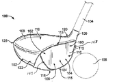
図1は、本発明の少なくともいくつかの例のゴルフドライバの形態の打球装置100を示し、この種類の打球装置100のヘッド102の例示的態様を図2〜16Aに示す。図1に示すように、打球装置100は、打球ヘッド102と、打球ヘッド102に接続され、そこから延びるシャフト104とを含む。また、図1には、使用されるボール106が、打球装置100によって打たれる位置で示されている。図1の打球装置100の打球ヘッド102は、ボディ108に接続されたフェース112を有し、ボディからホーゼル109が延びている。本発明を逸脱することなく、当技術分野において公知であり、使用されている従来のホーゼルおよび/またはヘッド/シャフト相互接続構造を含む任意の所望のホーゼルおよび/またはヘッド/シャフト相互接続構造を使用することができる。参照のために、ヘッド102は概して、上部116、下部またはソール118、ホーゼル109に近接するヒール120、ホーゼル109から遠いトウ122、前面124および背面または後部126を有する。ヘッド102の形状および設計は、装置100の所期の用途によって部分的に決まることもある。図1に示すクラブ100において、クラブ100は、ボールを正確に遠くまで打つためのドライバまたはウッドタイプゴルフクラブとしての使用のために設計されているため、ヘッド102は相対的に大きな体積を有する。たとえば異なるタイプのゴルフクラブのための他の用途において、ヘッドは、異なる寸法および構成を有するように設計されてもよい。ドライバとして構成される場合、クラブヘッドは、少なくとも400cc、いくつかの構造においては少なくとも450ccまたはさらに少なくとも460ccの体積を有しうる。他のクラブヘッドの場合の他の適切なサイズは当業者によって容易に決定しうる。
FIG. 1 shows a ball
図1に示す例示的態様において、ヘッド102は、内部キャビティを画定する中空構造(たとえば、フェース112およびボディ108によって画定される)を有する。したがって、ヘッド102は、その中に画定された複数の内面を有する。一つの態様において、中空の中心キャビティは空気で満たされてもよい。しかし、他の態様において、ヘッド102は、別の材料、たとえばフォームで満たされることもできる。なおさらなる態様においては、ヘッドの固形材料が体積の比較的大きな割合を占めてもよく、ヘッドは、より小さなキャビティを有する、または内部キャビティを全く有しないこともできる。いくつかの態様において、内部キャビティは完全には包囲されなくてもよいことが理解されよう。
In the exemplary embodiment shown in FIG. 1,
図1および11に示すように、フェース112は、ヘッド102の前面124に位置し、その上に位置する打球面110と、打球面110とは反対側の内面111とを有する。打球面110は、概してフェース112の外面であり、この外面は使用中にボール106に対面するように構成され、たとえばスイングによって装置100が動かされたとき、ボール106を打つように適合されている。図示するように、打球面110は、相対的に平坦であり、フェース112の大部分を占める。フェース112は複数の外縁127を有し、外縁は上縁113、下縁115ならびに側縁(ヒール縁148およびトウ縁149を含む)を含む。フェースの縁127は、使用中にボール106と接触するように具体的に設計されたフェース112の区域の境界として画定することができ、ボール接触に適するように意図的に平坦化および平滑化されたフェース112の区域の境界として認識することができる。参照のために、フェース上縁113およびヘッド102のヒール120に最も近いフェース112の部分を「ハイヒール区域」160と呼び、フェース上縁113およびヘッド102のトウ122に最も近いフェース112の部分を「ハイトウ区域」162と呼び、フェース下縁115およびヘッド102のヒール120に最も近いフェース112の部分を「ロウヒール区域」164と呼び、フェース下縁115およびヘッド102のトウ122に最も近いフェース112の部分を「ロウトウ区域」166と呼ぶ。概念的に、これらの区域160〜166は、実質的に等しいサイズの四分円(および/またはフェース112の幾何学的中心から延びる四分円)と認識し、そう呼ぶことができるが、必ずしも対称の寸法を有するわけではない。フェース112は、当技術分野において公知であり、一般的であるように、上下方向および/またはヒール−トウ方向にいくらかのカーブ(たとえばバルジおよびロール特性)を含みうる。他の態様においては、表面110がフェース112の異なる割合を占めることもできるし、またはボディ108が、その上に多数の打球面110を有することもできる。図1に示す例示的態様において、打球面110はわずかに傾斜して(すなわちロフト角を有して)、打ったときにボール106にわずかなリフトおよびスピンを加える。他の例示的態様において、打球面110は、ボール106の弾道に影響するように異なる傾斜またはロフト角を有しうる。さらには、いくつかの態様において、フェース112は、可変性の厚みを有してもよく、および/または一つまたは複数の内部もしくは外部インサートを有してもよい。
As shown in FIGS. 1 and 11, the
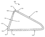
フェース112、ボディ108および/またはホーゼル109は、単一のピースとして形成されることもできるし、または接合される別々のピースとして形成されることもできることが理解されよう。図11〜16Aの例示的態様に示すように、フェース112はフェースフレーム部材128の一部として形成することができ、一つまたは複数の壁125がフェース112の縁127から後方に延びている。この構成はカップフェース構造とも知られている。ボディ108は、フェースフレーム部材128の壁125に接合された別々のピースとして形成されることができる。さらには、図11〜16Aの例示的態様にやはり示すように、ボディ108は、一つのピースまたは多数のピースであることができるバックボディ部材129によって部分的に形成することができる。フェースフレーム部材128の壁125がバックボディ部材129と組み合わさってヘッド102のボディ108を形成する。これらのピースは、一体接合技術、たとえば溶接、セメンティングまたは接着剤接合によって接続されてもよい。これらのパーツを接合するための他の公知の技術を、解放可能な機械的係合技術を含む多くの機械的接合技術を含め、同様に使用することもできる。必要に応じて、ホーゼル109は、フェースフレーム部材128の一部として一体に形成されてもよい。さらには、フェースフレーム部材128とバックボディ部材129との間にガスケット(図示せず)が含まれてもよい。
It will be appreciated that the
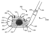
図17は、本発明の少なくともいくつかの例のゴルフアイアンの形態の打球装置200を示し、この種類の打球装置200のヘッド202の例示的態様を図18〜28に示す。図1の打球装置100と図17の打球装置200との間の多くの共通のコンポーネントは、「200」系列の参照数字を使用する以下の説明において、同様の参照数字を使用して参照する。打球装置200は、シャフト204およびシャフト204に取り付けられたゴルフクラブヘッド202を含む。図17のゴルフクラブヘッド202は、本発明の例の任意のアイアンまたはハイブリッドタイプゴルフクラブヘッドを代表することができる。
FIG. 17 shows a ball
図18〜28に示すように、ゴルフクラブヘッド202は、フェース212を有するボディ部材208、およびシャフト204の取り付けのためにボディ208から延びるホーゼル209を含む。参照のために、ヘッド202は概して、上部216、下部またはソール218、ホーゼル209に近接するヒール220、ホーゼル209から遠いトウ222、前面224および背面または後部226を有する。ヘッド202の形状および設計は、装置200の所期の用途によって部分的に決まることもある。ヒール部220はホーゼル209に取り付けられかつ/またはそこから延びる(たとえば単一または一体のワンピース構成、別々の接続された要素、などとして)。
As shown in FIGS. 18-28, the
フェース212は、ヘッド202の前面224に位置し、その上に位置する打球面210、および打球面210とは反対側の内面211を有する。打球面210は、概してフェース212の外面であり、この外面は使用中にボール(図示せず)に対面するように構成され、たとえばスイングによって装置200が動かされたとき、ボールを打つように適合されている。図示するように、打球面210は、相対的に平坦であり、フェース212の大部分を占める。打球面210は、打球中にフェース212から水および草を除去するための溝252(たとえば、図示例ではフェース212を横切って延びる概して水平な溝252)を含みうる。当然、本発明を逸脱することなく、従来の溝パターンおよび/または溝構成を含む任意の数の溝、所望の溝パターンおよび/または溝構成を設けることができる(あるいは必要に応じて溝パターンなしであっても)。
The
参照のために、フェース上縁213およびヘッド202のヒール220に最も近いフェース212の部分を「ハイヒール区域」260と呼び、フェース上縁213およびヘッド202のトウ222に最も近いフェース212の部分を「ハイトウ区域」262と呼び、フェース下縁215およびヘッド202のヒール220に最も近いフェース212の部分を「ロウヒール区域」264と呼び、フェース下縁215およびヘッド202のトウ222に最も近いフェース212の部分を「ロウトウ区域」266と呼ぶ。概念的に、これらの区域260〜266は、実質的に等しいサイズの四分円(および/またはフェース212の幾何学的中心から延びる四分円)と認識し、そう呼ぶことができるが、必ずしも対称の寸法を有するわけではない。フェース212は、当技術分野において公知であり、一般的であるように、上下方向および/またはヒール−トウ方向にいくらかのカーブ(たとえばバルジおよびロール特性)を含みうる。他の態様においては、表面210がフェース212の異なる割合を占めることもできるし、またはボディ208が、その上に多数の打球面210を有することもできる。図24に示す例示的態様でわかるように、打球面210は傾斜して(すなわちロフト角を有して)、打ったときにボールに相当な程度のリフトおよびスピンを加える。他の例示的態様において、打球面210は、ボールの弾道に影響するように異なる傾斜またはロフト角を有しうる。さらには、いくつかの態様において、フェース212は、可変性の厚みを有してもよく、および/または一つまたは複数の内部もしくは外部インサートを有してもよい。フェース212、ボディ208および/またはホーゼル209は、単一のピースとして形成されることもできるし、または接合される別々のピースとして形成されることもできることが理解されよう。
For reference, the portion of the
ゴルフクラブヘッド202のボディ部材208は、当技術分野において従来公知であり、使用されている材料、たとえば鋼、チタン、アルミニウム、タングステン、グラファイト、ポリマーもしくは複合材、またはその組み合わせを含む多種多様な異なる材料から構築されうる。また、必要に応じて、クラブヘッド202を、任意の数のピース(たとえば別々のフェースプレートなどを有する)から、ならびに/または鋳造、鍛造、溶接、および/もしくは当技術分野において公知であり、使用される他の方法をたとえば含む任意の構築技術によって、作製することもできる。
The
打球装置100、200は、図1および17に模式的に示すように、打球ヘッド102、202に接続または他のやり方で係合したシャフト104、204を含むことができる。シャフト104、204は、打球装置100、200をスイングしてボール106を打つためにユーザによって把持されるように適合されている。シャフト104、204は、図1および17に示すように、たとえばホーゼル109、209に接続することによってヘッド102、202に接続された別個のピースとして形成されることができる。他の例示的態様においては、シャフト104、204の少なくとも一部分がヘッド102、202と一体のピースであってもよいし、および/またはヘッド102、202は、ホーゼル109、209を含まなくてもよいし、または内部ホーゼル構造を含んでもよい。本発明の範囲を逸脱することなく、なおさらなる態様が考えられる。シャフト104、204は、金属、セラミックス、ポリマー、複合材または木を含む多様な材料の一つまたは複数から構築されうる。いくつかの例示的態様において、シャフト104、204または少なくともその部分は、金属、たとえばステンレス鋼もしくはチタン、または複合材、たとえばカーボン/グラファイト繊維・ポリマー複合材で構築されうる。しかし、本発明の範囲を逸脱することなく、シャフト104、204は、当技術分野において公知であり、使用されている従来の材料を含む様々な材料で構築されうる。図17に示すように、ゴルフクラブシャフト104、204を掴むために用いるスリップ抵抗面をゴルファーに提供するように、グリップ要素205をシャフト104、204上に配置することができる。当技術分野において公知であり、使用される従来のやり方(たとえば接着剤もしくはセメント、ねじ、または他の機械的コネクタ経由、スウェッジング/スウェージングなど)を含む任意の所望のやり方で、グリップ要素205をシャフト104、204に取り付けることができる。
The ball
概して、打球装置100、200のヘッド102、202は、少なくとも一つのチャネル130をその上に含むフェース112、212を有する。一つの態様において、フェース112、212は複数のチャネル130を含み、チャネル130はフェース112、212の一つまたは複数の縁127、227に近接して位置している。一つまたは複数のチャネル130は、フェース112、212の他の縁127、227に比べ、フェース112、212の一つの縁127、227に「最も近接して」位置しうる。さらには、一つまたは複数のチャネル130は、フェース112、212の中心に比較的近位である一方の端部、およびフェース112、212の中心から遠位でフェース112、212の外縁127、227に比較的近位である反対側の端部を有しうる。図2〜10は、ウッドタイプ打球装置100A〜Jの異なる態様を示し、これらはそれぞれ、フェース112の一つまたは複数の外縁127、227に近接して位置する複数のチャネル130を有するヘッド102を含む。図18〜25は、アイアンタイプ打球装置200A〜Fの異なる態様を示し、これらはそれぞれ、フェース112、212の一つまたは複数の外縁127、227に近接して位置する複数のチャネル130を有するヘッド202を含む。これらの様々な態様を以下でさらに詳細に説明する。本明細書においてチャネル130の様々な態様を記載する上で使用する「チャネル」の定義が、伝統的なフェース溝、たとえば図18〜25に示すフェース溝252または図2〜10に示すフェース溝152を包含しないということが明確に理解されよう。そのような伝統的なフェース溝152、252の構造および機能、ならびに他の特徴は、本明細書に記載のチャネル130のそれらと異なる。さらには、チャネル130は概して、フェース112、212の通常の打撃ゾーンまたは高CORゾーンには位置しておらず、一方、フェース溝252はフェース112、212の中心に位置しうる。一つの態様において、任意のチャネル130のどの部分も、フェース112、212の幾何学的中心から約1.5インチ距離以内に延びていない。
Generally, the
図2〜10および18〜25に示す態様において、各フェース112、212は、フェース112、212の中心に近接して位置する最高応答領域または区域140を有する。フェース112、212の「応答」とは、概して、ボールとの衝突時にエネルギーを伝達するフェース112、212(またはその一領域)の能力を意味し、上記の反発係数(COR)として表すことができる。これらの態様において、最高応答領域140は実質的に各チャネル130に向かって一方向に拡大している。概して、チャネル130はフェース112、212の可撓性を増大させ、その結果、最高応答領域140はチャネル130に向かって一方向に拡大される。一つの態様において、フェース112、212の中心は、ボールとの衝突時に生じるトランポリン様効果による高COR応答を示し、チャネル130が付与する増大した可撓性は、最大程度のトランポリン効果を経験するフェース112、212の領域の形状を変化させる。本明細書で使用する「一方向に拡大している」とは、最高応答領域140が、本明細書において定義されるチャネル130を含まないことを除けば同一のフェースにおける最高応答領域に比べ、一般的な一方向に拡大、変形または他のやり方で延伸していることをいう。一つの態様において、一方向の拡大は、フェース112、212の略中心に位置する略円形区域からのずれによって測定することができる。たとえば図18〜25に示すように、この略円形区域がわずかに楕円形でありうることが理解されよう。一方向の拡大のおおよその方向を、各態様において矢印142で示し、フェース112、212の中心での略円形区域に対する最大応答領域140のおおよその拡大を、比較的明るいおよび暗い影付きの区域によって模式的に示す。略円形区域は、本明細書において定義されるチャネル130を含まないことを除けば同一のフェースにおける最高応答領域を表すように意図されている。本明細書において言及されるフェース112、212の「中心」は、フェース112、212の幾何学的中心および/またはフェース112、212の重心でありうる。図2〜10および18〜25の態様において、幾何学的中心および重心は略同一の場所を有する。以下に記載のいくつかの態様において、領域140は、二つ以上の隣接するチャネル130の間に位置する地点、たとえば隣接するチャネル130の間の略中間点に向かって一方向に拡大142しうる。最高応答領域140が、フェース112、212の他の区域に比べ、高い可撓性および低い剛性も有しうるものであり、それに応じて言及されうることが理解されよう。
In the embodiment shown in FIGS. 2-10 and 18-25, each
図2は、ウッドタイプヘッド102を有する打球装置100Aの一態様を示し、ヘッドは、フェース112の外縁127に近接して位置する四つの細長いチャネル130を含む。各チャネル130は、他の二つの残りのチャネル130に比べ、三つの残りのチャネル130の一つに最も近接して位置しており、これらの最も近接したチャネル130を、チャネル130の「対」と概念的に呼ぶことができる。一方の対のチャネル130はフェース112のハイトウ区域162に位置し、他方の対のチャネル130はフェース112のロウヒール区域164に位置している。それぞれのチャネル130は、フェース112の外縁127に接触し、各縁127に対して横方向または実質的に横方向に、フェース112の各外縁127から内向きに延びる。ハイトウ区域162におけるチャネル130では、一方のチャネル130は、フェース112のトウ縁149から内向きに延び、他方のチャネル130は、トウ縁149に最も近接したフェースの上縁113から内向きに延びる。ロウヒール区域164におけるチャネル130では、一方のチャネル130は、フェース112のヒール縁148から内向きに延び、他方のチャネル130は、ヒール縁148に最も近接したフェース112の下縁115から内向きに延びる。さらには、図2において矢印142で示すように、最高応答領域140はチャネル130に向かって一方向に拡大している。より具体的には、この態様において、最高応答領域140は、各対のチャネル130の間の中間点に概して向かう方向で、フェース112のハイトウ区域162およびロウヒール区域164に向かって拡大している。
FIG. 2 illustrates one embodiment of a ball
図2に示す態様において、チャネル130は、図11に示すように、フェース112の厚みの一部分を通って延びる陥凹として形成される。さらには、チャネル130は、フェース112の材料の可撓性よりも大きい可撓性を有する可撓性材料144でそれぞれ満たされている。たとえば、可撓性材料144は、ゴムまたは別のポリマー材料でありうるし、あるいは、相対的に可撓性の金属、セラミックス、複合材などでありうる。一つの態様において、可撓性材料144の可撓性は、フェース112の材料の可撓性の少なくとも二倍でありうる。材料の可撓性は、各材料の弾性率、または可撓性の別の定量的測定値を使用して定量化することができる。様々な態様において、チャネル130を可撓性材料144で部分的または完全に満たすことができることが理解されよう。図12に示すように、別の態様において、チャネル130は、フェース112における陥凹として形成することができ、可撓性材料144で満たされていなくてもよい。図13〜14に示すように、他の態様において、チャネル130は、フェース112を貫通して延びるスリットとして形成することができる。図13に示す態様において、チャネル130はフェース112を貫通して延び、可撓性材料144で満たされており、図14に示す態様において、チャネル130は可撓性材料144で満たされていない。いくつかの態様において、一つまたは複数のチャネル130が満たされていることがあり、一つまたは複数の他のチャネル130が満たされていないことがあること、および異なるチャネル130が異なる材料144で満たされていることがあることが理解されよう。さらには、図11〜14に示すチャネル130は概して一貫した奥行きを有するが、一つまたは複数のチャネル130が異なる奥行きを有しうることが理解されよう。さらに、一つまたは複数のチャネル130が一貫した奥行きを有しうるが、フェース112の輪郭および/または厚みの変動が理由で、チャネル130の一部分のみがフェース112を通って延びることがあることが理解されよう。なおさらに、図11〜14には一つのチャネル130のみが示されており、他のチャネル130は図示されたチャネル130と同一の構成または異なる構成を有しうるものであり、同一のフェース112における複数のチャネル130は異なる構成を有しうる。
In the embodiment shown in FIG. 2, the
さらには、少なくともいくつかのチャネル130は、互いに斜角に置いた対として配設することができ、最高応答領域140は、各対のチャネル130に向かって一方向に拡大している。たとえば図2に示すように、チャネル130は、フェース112の隣接する外縁127から内向きに延び、それらの仮想交差地点において90°以下の角度で置かれている。概念的には、図2のフェース112のハイトウ区域162におけるチャネル130を一つの対と呼ぶことができ、フェース112のロウヒール区域164におけるチャネル130を別の対と呼ぶことができる。この構成のさらなる例は、以下でさらに詳細に説明する図3〜6および9〜10ならびに図23〜25に見ることができる。以下でさらに詳細に説明する図5および22にたとえば示すように、別の例として、チャネル130の対のうち少なくともいくつかは、90°を超える斜角で配設することができる。なおさらに、以下でさらに詳細に説明する図7〜8および18〜21にたとえば示すように、少なくともいくつかのチャネル130は互いに平行または概して平行でありうる。図2〜16Aおよび18〜28に示すチャネル構成ならびに他の構成のいずれかとの関連でこれらの配設を使用することができることが理解されよう。
In addition, at least some of the
図3は、ウッドタイプヘッド102を有する打球装置100Bの一態様を示し、ヘッドは、図2に示すヘッド102の構成と同様の構成において、フェース112の外縁127に近接して位置する二つの対の細長いチャネル130を含む。図2の態様と同様に、一方の対のチャネル130はフェース112のハイトウ区域162に位置し、他方の対のチャネル130はフェース112のロウヒール区域164に位置している。それぞれのチャネル130は、各縁127に対して横方向または実質的に横方向に、フェース112の外縁127から内向きに延びる。しかし、図3に示す態様において、チャネル130はフェース112の外縁127を超えて延び、ボディ108の一部分を通って後方に延びる。さらには、図3において矢印142で示すように、最高応答領域140は、図2に示す態様と同様に、チャネル130に向かって一方向に拡大している。より具体的には、この態様において、最高応答領域140は、各対のチャネル130の間の中間点に概して向かう方向で、フェース112のハイトウ区域162およびロウヒール区域164に向かって拡大している。
FIG. 3 shows an embodiment of a ball
図3に示す態様において、チャネル130は、図15に示すように、フェース112の厚みの一部分を通って延びる陥凹として形成される。図16に示すように、別の態様において、チャネル130は、フェース112を貫通して延びるスリットとして形成することができる。図15〜16に示す態様において、チャネル130は材料で満たされていない。しかし、図11、13、14Aおよび16Aに示すように、他の態様において、チャネル130を可撓性材料144で部分的または完全に満たすことができる。ヘッド102がフェースフレーム部材128を含む図15〜16Aに示す態様において、チャネル130はフェースフレーム部材128の壁125の一部分を通って延びうる。別の態様において、チャネル130は壁125全体を通って延びうるものであり、バックボディ部材129内に延びうる。他の態様において、ヘッド102がフェースフレーム部材128を含まないことがあることが理解されよう。図11〜14に関して同様に先に記載のように、いくつかの態様において、一つまたは複数のチャネル130が満たされていることがあり、一つまたは複数の他のチャネル130が満たされていないことがあること、および異なるチャネル130が異なる材料144で満たされていることがあることが理解されよう。さらには、図15〜16Aに示すチャネル130は概して一貫した奥行きを有するが、一つまたは複数のチャネル130が異なる奥行きを有しうることが理解されよう。さらに、一つまたは複数のチャネル130が一貫した奥行きを有しうるが、フェース112の輪郭および/または厚みの変動が理由で、チャネル130の一部分のみがフェース112を通って延びることがあることが理解されよう。なおさらに、図15〜16Aには一つのチャネル130のみが示されており、他のチャネル130は図示されたチャネル130と同一の構成または異なる構成を有しうるものであり、同一のフェース112における複数のチャネル130は異なる構成を有しうる。
In the embodiment shown in FIG. 3, the
別の態様において、たとえば図14Aおよび16Aに示すように、チャネル130は、フェース112の厚みの一部分を通って延びるフェース112の内面111上の陥凹でありうる。図14Aに示す態様において、チャネル130は、フェース112の内面111上に位置してフェース112の厚みの一部分を通って延びる陥凹である。図16Aに示す態様において、チャネル130は、フェースの内面111上に位置してフェース112の厚みの一部分を通って延び、また壁125およびボディ108の一部分内に後方に延びる、陥凹である。さらには、図14Aおよび16Aに示す態様において、チャネル130は可撓性材料144をその中に含む。しかし、別の態様において、チャネル130が可撓性材料144をその中に有さないことがあり、図11〜14および15〜16に関して先に記載のように変動しうることが理解されよう。
In another embodiment, for example, as shown in FIGS. 14A and 16A, the
図4は、ウッドタイプヘッド102を有する打球装置100Cの一態様を示し、ヘッドは、図2に示すヘッド102の構成と同様の構成において、フェース112の外縁127に近接して位置する二つの対の細長いチャネル130を含む。図2の態様と同様に、一方の対のチャネル130はフェース112のハイトウ区域162に位置し、他方の対のチャネル130はフェース112のロウヒール区域164に位置している。それぞれのチャネル130は、各縁127に対して横方向または実質的に横方向に、フェース112の外縁127に隣接する地点から内向きに延びる。しかし、図4に示す態様において、チャネル130はフェース112の外縁127に延びず、むしろチャネル130は外縁127の手前で止まる。さらには、図4において矢印142で示すように、最高応答領域140は、図2に示す態様と同様に、チャネル130に向かって一方向に拡大している。より具体的には、この態様において、最高応答領域140は、各対のチャネル130の間の中間点に概して向かう方向で、フェース112のハイトウ区域162およびロウヒール区域164に向かって拡大している。
FIG. 4 shows an embodiment of a ball
図5は、ウッドタイプヘッド102を有する打球装置100Dの一態様を示し、ヘッドは、フェース112の外縁127に近接して位置する二つの対の細長いチャネル130を含む。図2の態様と同様に、一方の対のチャネル130はフェース112のハイトウ区域162に位置し、他方の対のチャネル130はフェース112のロウヒール区域164に位置している。しかし、図5の態様において、それぞれのチャネル130は、フェース112の外縁127と概して平行に、各縁127に隣接して延びる。ハイトウ区域162におけるチャネル130では、一方のチャネル130は、フェース112のトウ縁149と概して平行に延び、他方のチャネル130は、トウ縁149に最も近接したフェース112の上縁113と概して平行に延びる。ロウヒール区域164におけるチャネル130では、一方のチャネル130は、フェース112のヒール縁148と概して平行に延び、他方のチャネル130は、ヒール縁148に最も近接したフェース112の下縁115と概して平行に延びる。さらには、図5に示す態様における二つのチャネル130、具体的には最上部または最下部のチャネル130は曲線状である。さらに、図5において矢印142で示すように、最高応答領域140は、図2に示す態様と同様に、チャネル130に向かって一方向に拡大している。より具体的には、この態様において、最高応答領域140は、各対のチャネル130の間の中間点に概して向かう方向で、フェース112のハイトウ区域162およびロウヒール区域164に向かって拡大している。
FIG. 5 shows one embodiment of a ball
図6は、ウッドタイプヘッド102を有する打球装置100Eの一態様を示し、ヘッドは、フェース112の外縁127に近接して位置する二つの対の細長いチャネル130を含む。一方の対のチャネル130はフェース112のハイヒール区域160に位置し、他方の対のチャネル130はフェース112のロウトウ区域166に位置している。それぞれのチャネル130は、図2に示す態様のチャネル130と同様に、各縁127に対して横方向または実質的に横方向に、フェース112の外縁127に隣接する地点から内向きに延びる。ハイヒール区域160におけるチャネル130では、一方のチャネル130は、フェース112のヒール縁148から内向きに延び、他方のチャネル130は、ヒール縁148に最も近接したフェースの上縁113から内向きに延びる。ロウトウ区域166におけるチャネル130では、一方のチャネル130は、フェース112のトウ縁149から内向きに延び、他方のチャネル130は、トウ縁149に最も近接したフェース112の下縁115から内向きに延びる。さらには、図6において矢印142で示すように、最高応答領域140はチャネル130に向かって一方向に拡大している。より具体的には、この態様において、最高応答領域140は、各対のチャネル130の間の中間点に概して向かう方向で、フェース112のハイヒール区域160およびロウトウ区域166に向かって拡大している。
FIG. 6 shows one embodiment of a ball
図7は、ウッドタイプヘッド102を有する打球装置100Fの一態様を示し、ヘッドは、フェース112の外縁127に近接して位置する一つの対の細長いチャネル130を含む。チャネル130は、フェース上縁113に最も近接して位置し、フェース上縁113に対して横方向または実質的に横方向に、フェース112の上縁113から内向きに延びる。さらには、図7において矢印142で示すように、最高応答領域140はチャネル130に向かって一方向に拡大している。より具体的には、この態様において、最高応答領域140は、この対のチャネル130の間の中間点に概して向かう方向で、フェース112の上縁113に向かって拡大している。そのような構成は、たとえば、フェース112の高い位置でドライバを頻繁に打つゴルファーに有用でありうるものであり、この打撃は、非常に長いティーを使用するときに、またはゴルファー(たとえばダウンスイング時に彼/彼女の肩を下げるゴルファー)のスイングの結果として起こりうる。
FIG. 7 shows one embodiment of a ball
図8は、ウッドタイプヘッド102を有する打球装置100Gの一態様を示し、ヘッドは、フェース112の外縁127に近接して位置する一つの対の細長いチャネル130を含む。チャネル130は、フェース下縁115に最も近接して位置し、フェース下縁115に対して横方向または実質的に横方向に、フェース112の下縁115から内向きに延びる。さらには、図8において矢印142で示すように、最高応答領域140はチャネル130に向かって一方向に拡大している。より具体的には、この態様において、最高応答領域140は、この対のチャネル130の間の中間点に概して向かう方向で、フェース112の下縁115に向かって拡大している。そのような構成は、たとえば、フェース112の低い位置でドライバを頻繁に打つゴルファーに有用でありうるものであり、この打撃は、大きいフェース面積を有するドライバとともに相対的に短いティーを使用するときに、またはゴルファー(たとえばダウンスイング時に彼/彼女の頭を上げるゴルファー)のスイングの結果として起こりうる。
FIG. 8 illustrates one embodiment of a ball
図9は、ウッドタイプヘッド102を有する打球装置100Hの一態様を示し、ヘッドは、フェース112の外縁127に近接して位置する一つの対の細長いチャネル130を含む。チャネル130は、ヒール120に最も近接して位置し、縁148に対して横方向または実質的に横方向に、ヒール縁148でのフェース外縁127から内向きに延びる。さらには、図9において矢印142で示すように、最高応答領域140はチャネル130に向かって一方向に拡大している。より具体的には、この態様において、最高応答領域140は、この対のチャネル130の間の中間点に概して向かう方向で、フェース112のヒール120に向かって拡大している。
FIG. 9 shows one embodiment of a ball
図10は、ウッドタイプヘッド102を有する打球装置100Iの一態様を示し、ヘッドは、フェース112の外縁127に近接して位置する一つの対の細長いチャネル130を含む。チャネル130は、トウ122に最も近接して位置し、縁149に対して横方向または実質的に横方向に、トウ縁149でのフェース外縁127から内向きに延びる。さらには、図9において矢印142で示すように、最高応答領域140はチャネル130に向かって一方向に拡大している。より具体的には、この態様において、最高応答領域140は、この対のチャネル130の間の中間点に概して向かう方向で、フェース112のトウ122に向かって拡大している。
FIG. 10 illustrates one embodiment of a ball striking device 100I having a wood-
先に記載し図4〜10に示す態様において、図11〜16Aに関して先に記載のように、チャネル130は、フェース112を部分的通ってまたは貫通して延びうるものであり、空にしても可撓性材料144で部分的または完全に満たしてもよい。さらには、先に記載し図4〜10に示す態様におけるチャネル130は、図2〜3および11〜16Aに関して先に記載の任意の他の構成または変形を有しうる。
In the embodiment described above and shown in FIGS. 4-10, the
図18は、アイアンタイプヘッド202を有する打球装置200Aの一態様を示し、ヘッドは、フェース212の外縁227に近接して位置する一つの対の細長いチャネル130を含む。チャネル130は、フェース下縁215に最も近接して位置し、フェース下縁215に対して横方向または実質的に横方向に、フェース212の下縁215から内向きに延びる。さらには、図18において矢印142で示すように、最高応答領域140はチャネル130に向かって一方向に拡大している。より具体的には、この態様において、最高応答領域140は、この対のチャネル130の間の中間点に概して向かう方向で、フェース212の下縁215に向かって拡大している。図26に示すように、この態様において、チャネル130はフェース212の厚みの一部分を通って延び、可撓性材料144で少なくとも部分的に満たされている。他の態様において、チャネル130は、図2〜3および11〜16Aに関して先に記載の任意の構成または変形を有しうる。たとえば、図11〜16Aに関して先に記載のように、一つまたは複数のチャネル130は、フェース212を部分的通ってまたは貫通して延びうるものであり、かつ/あるいは、空にしても可撓性材料144で部分的または完全に満たしてもよい。先に同様に記載のように、いくつかの態様において、一つまたは複数のチャネル130が満たされていることがあり、一つまたは複数の他のチャネル130が満たされていないことがあること、および異なるチャネル130が異なる材料144で満たされていることがあることが理解されよう。別の例として、図26に示すチャネル130は概して一貫した奥行きを有するが、一つまたは複数のチャネル130が異なる奥行きを有しうることが理解されよう。さらなる例として、一つまたは複数のチャネル130が一貫した奥行きを有しうるが、フェース212の輪郭および/または厚みの変動が理由で、チャネル130の一部分のみがフェース212を通って延びることがあることが理解されよう。なおさらに、図26には一つのチャネル130のみが示されており、他のチャネル130は図示されたチャネル130と同一の構成または異なる構成を有しうるものであり、同一のフェース212における複数のチャネル130は異なる構成を有しうる。
FIG. 18 illustrates one embodiment of a ball
図19は、アイアンタイプヘッド202を有する打球装置200Bの一態様を示し、ヘッドは、フェース212の外縁227に近接して位置する一つの対の細長いチャネル130を含む。チャネル130は、フェース上縁213に最も近接して位置し、フェース上縁213に対して横方向または実質的に横方向に、フェース212の上縁213から内向きに延びる。さらには、図19において矢印142で示すように、最高応答領域140はチャネル130に向かって一方向に拡大している。より具体的には、この態様において、最高応答領域140は、この対のチャネル130の間の中間点に概して向かう方向で、フェース212の上縁213に向かって拡大している。
FIG. 19 shows one embodiment of a ball
図20は、アイアンタイプヘッド202を有する打球装置200Cの一態様を示し、ヘッドは、図18に示す態様と同様の構成において、フェース212の外縁227に近接して位置する一つの対の細長いチャネル130を含む。チャネル130は、フェース下縁215に最も近接して位置し、フェース下縁215に対して横方向または実質的に横方向に、フェース212の下縁215から内向きに延びる。しかし、図20に示す態様において、チャネル130はフェース212の下縁215を超えて延び、ボディ208の一部分を通って後方に延びる。さらには、図20において矢印142で示すように、最高応答領域140はチャネル130に向かって一方向に拡大している。より具体的には、この態様において、最高応答領域140は、この対のチャネル130の間の中間点に概して向かう方向で、フェース212の下縁215に向かって拡大している。
FIG. 20 illustrates one embodiment of a ball
図21は、アイアンタイプヘッド202を有する打球装置200Dの一態様を示し、ヘッドは、図18に示す態様と同様の構成において、フェース212の外縁227に近接して位置する一つの対の細長いチャネル130を含む。チャネル130は、フェース下縁215に最も近接して位置し、フェース下縁215に対して横方向または実質的に横方向に、フェース212の下縁215から内向きに延びる。しかし、図21に示す態様において、チャネル130はフェース212の下縁215に延びず、むしろチャネル130は下縁215の手前で止まる。さらには、図20において矢印142で示すように、最高応答領域140はチャネル130に向かって一方向に拡大している。より具体的には、この態様において、最高応答領域140は、この対のチャネル130の間の中間点に概して向かう方向で、フェース212の下縁215に向かって拡大している。
FIG. 21 shows one embodiment of a ball
図22は、アイアンタイプヘッド202を有する打球装置200Eの一態様を示し、ヘッドは、フェース212の外縁227に近接して位置する一つの対の細長いチャネル130を含む。この対のチャネル130はフェース212のロウヒール区域264に位置している。図22の態様において、それぞれのチャネル130は、フェース212の最も近接した外縁227と概して平行に、各縁227に隣接して延びる。さらには、図22において矢印142で示すように、最高応答領域140はチャネル130に向かって一方向に拡大している。より具体的には、この態様において、最高応答領域140は、この対のチャネル130の間の中間点に概して向かう方向で、フェース212のロウヒール区域264に向かって拡大している。
FIG. 22 illustrates one embodiment of a ball
図23は、アイアンタイプヘッド202を有する打球装置200Fの一態様を示し、ヘッドは、フェース212の外縁227に近接して位置する一つの対の細長いチャネル130を含む。この対のチャネル130はフェース212のハイトウ区域262に位置している。図23の態様において、それぞれのチャネル130は、フェース212の最も近接した外縁227と概して平行に、各縁227に隣接して延びる。さらには、図23において矢印142で示すように、最高応答領域140はチャネル130に向かって一方向に拡大している。より具体的には、この態様において、最高応答領域140は、この対のチャネル130の間の中間点に概して向かう方向で、フェース212のハイトウ区域262に向かって拡大している。
FIG. 23 shows one embodiment of a ball
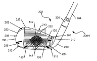
図24は、アイアンタイプヘッド202を有する打球装置200Gの一態様を示し、ヘッドは、フェース212の外縁227に近接して位置する二つの対の細長いチャネル130を含む。一方の対のチャネル130はフェース212のハイトウ区域262に位置し、他方の対のチャネル130はフェース212のロウヒール区域264に位置している。図24の態様において、それぞれのチャネル130は、フェース212の最も近接した外縁227に対して横方向または実質的に横方向に延びる。さらには、図24において矢印142で示すように、最高応答領域140はチャネル130に向かって一方向に拡大している。より具体的には、この態様において、最高応答領域140は、各対のチャネル130の間の中間点に概して向かう方向で、フェース212のハイトウ区域262およびロウヒール区域264に向かって拡大している。
FIG. 24 shows one embodiment of a ball
図25は、アイアンタイプヘッド202を有する打球装置200Hの一態様を示し、ヘッドは、フェース212の外縁227に近接して位置する四つの細長いチャネル130を含む。一方の対のチャネル130はフェース212のロウトウ区域266に位置し、別の対のチャネル130はフェース212のロウヒール区域264に位置している。図25の態様において、それぞれのチャネル130は、フェース212の最も近接した外縁227に対して横方向または実質的に横方向に延びる。さらには、図25において矢印142で示すように、最高応答領域140はチャネル130に向かって一方向に拡大している。より具体的には、この態様において、最高応答領域140は、この対のチャネル130の間の中間点に概して向かう方向で、フェース212のロウトウ区域266およびロウヒール区域に向かって拡大している。さらに、図25においてやはり矢印142で示すように、フェース212の下縁215上のチャネル130は、最高応答領域140を、チャネル130の間の中間点に概して向かうように、フェース212の下縁215に向かって拡大させる。
FIG. 25 shows one embodiment of a ball
先に記載し図19〜25に示す態様において、図11〜16Aおよび26に関して先に記載のように、チャネル130は、フェース212を部分的に通ってまたは貫通して延びうるものであり、空にしても可撓性材料144で部分的または完全に満たしてもよい。さらには、先に記載し図4〜10に示す態様におけるチャネル130は、図2〜3および11〜16Aおよび26に関して先に記載の任意の他の構成または変形を有しうる。
In the embodiment described above and shown in FIGS. 19-25, as described above with respect to FIGS. 11-16A and 26, the
図27および28は、フェース212よりむしろヘッド202のボディ208においてチャネル130を含む、打球ヘッド202のさらなる態様を示す。図27は、ヘッド202のソール218においてチャネル130を含む態様を示す。図27には示されていないが、この態様におけるチャネル130は、フェース212の下端215と平行または概して平行に延びうる。この態様において、チャネル130は、最高応答領域をフェース212の下端215に向かって一方向に拡大させる。図28は、ボディ208のヒール222部分の側面においてチャネル130を含む態様を示す。この態様において、チャネル130は、フェース212の側縁227の一つ(図28に示さず)と平行または概して平行に延びる。この態様において、チャネル130は、最高応答領域をヘッド202のトウ222に向かって一方向に拡大させる。図27〜28のチャネル130は、可撓性材料144を含まないものとして示されているが、他の態様において、これらのチャネル130は可撓性材料144を含みうる。さらにまたは代わりに、他のチャネル130をヘッド202上の他の場所に配置することにより、異なる様式で最高応答領域を一方向に拡大させることができることが理解されよう。図27〜28のヘッド202は、アイアンタイプ打球装置200で使用されるヘッド202として示され、記載されている。しかし、図27〜28の特徴を他の種類の打球装置、たとえば、図1〜16Aに示し先に記載するウッドタイプ打球装置100において利用することができることが理解されよう。ヘッド202の側面におけるチャネル130を、先に記載し図2〜16Aおよび18〜26に示す構成および態様のいずれかを含む打球ヘッド102、202において、フェース112、212におけるチャネル130に対する追加または補足として利用することができることも理解されよう。
FIGS. 27 and 28 illustrate a further embodiment of a
図2〜16Aおよび18〜28に示す態様を含むいくつかの異なる態様を上記で説明してきた。これらの様々な態様の特徴のいずれかを組み合わせかつ/または交換することができることが理解されよう。たとえば、フェース112、212は、フェース112、212の隣接する外縁127、227に対して、横方向または実質的に横方向に延びる一つまたは複数のチャネル130、およびフェース112、212の隣接する外縁127、227と概して平行に延びる、一つまたは複数のさらなるチャネル130を有しうる。別の例として、フェース112、212は、フェース112、212の縁127、227に延びるチャネル130、縁127、227を超えてボディ108、208内に延びるチャネル130、および/または隣接する縁112、212の手前で止まるチャネル130の組み合わせを有しうる。なおさらに、図2〜16Aおよび18〜28に示すすべての態様は、フェース112の外面(打球面)110においてチャネル130を含む。しかし、先に記載し図14Aおよび16Aに示すように、他の態様において、内面111は、さらにまたは代わりに、本明細書に記載のチャネルと同様の構造および機能を有する一つまたは複数のチャネル130を含みうる。いくつかの態様において、一つまたは複数のチャネル130、たとえば図5に示すチャネル130が直線経路に沿って延びないことがあり、曲線状でありうること、および/または、同定可能な方向に一つまたは複数のチャネル130が細長くないことがあることが理解されよう。
Several different embodiments have been described above, including the embodiments shown in FIGS. 2-16A and 18-28. It will be understood that any of these various aspect features may be combined and / or interchanged. For example, faces 112, 212 may include one or
種々の異なる方法でチャネル130をフェース112、212において形成することができる。一つの態様において、フェース112、212を製造した後に、たとえば切削、フライス削り、鍛造または他のそのような技術によって、一つまたは複数のチャネル130をフェース112、212において形成することができる。マルチピースヘッド102、202において、ヘッド102を完全に組み立てる前または後のいずれかにチャネル130をフェース112、212において形成することができることが理解されよう。別の態様において、たとえば、フェース112、212と一体的にチャネル130を形成する成形、鍛造などのための成形型を創製することにより、フェース112、212の製造時に一つまたは複数のチャネル130を形成することができる。さらなる態様において、任意の他の好適な技術を使用してチャネル130を形成することができる。さらには、一つまたは複数のチャネル130を上記のような可撓性材料144で満たすことができ、これは種々の異なる方法で行うことができる。たとえば、可撓性材料144を固体状態でチャネル130に挿入することができ、溶接、ろう付け、はんだ付け、接着剤、締まり嵌め、ファスナまたは他の好適な技術を使用してチャネル130内に保持することができる。別の例として、たとえば、反応して可撓性材料を形成する(たとえば化学反応または重合反応を通じて)溶融材料または試薬材料でチャネル130を満たすことにより、可撓性材料144を完全または部分的に液体の状態でチャネルに挿入することができる。さらなる例として、フェース112、212を製造する途中に可撓性材料144をチャネルに満たすことができる。なおさらなる態様において、任意の他の好適な技術を使用してチャネル130を可撓性材料144で満たすことができる。
本明細書に開示されるチャネル130を組み込むヘッド102、202は、打球装置またはその一部として使用することができる。たとえば、図1および17に示すゴルフクラブ100、200は、シャフトまたはハンドル104、204を、提供されるヘッド、たとえば上記のようなヘッド102、202に取り付けることによって製造することができる。本明細書で使用される、ヘッドを「提供する」とは、広く、物品を、その物品に対して実施される将来の動作のために利用可能またはアクセス可能にすることをいい、その物品を提供する当事者がその物品を製造、生産または供給したこと、あるいはその物品を提供する当事者がその物品の所有権または管理を有することを意味しない。他の態様において、本明細書に記載される原理にしたがって様々なタイプの打球装置を製造することができる。図11〜16Aに示すヘッド102を製造することは、上記のように、バックボディ部材129をフェースフレーム部材128に取り付けることを含みうる。さらには、たとえば上記の技術によってフェース112、212において一つまたは複数のチャネル130を形成することでフェース112、212の最高応答領域140の所望のサイズおよび構成を実現することによって、ヘッド102、202、ゴルフクラブ100、200または他の打球装置をある個人のためにフィッティングまたはカスタマイズすることができる。そのようなカスタマイズとしては、フェース112、212において一つもしくは複数のチャネル130を切削、フライス削り、または他のやり方で形成すること、および/または一つもしくは複数のチャネル130を可撓性材料で満たすことを挙げることができる。
The
本明細書に記載されるような打球装置およびそのためのヘッドは、既存の製品に対して多くの恩典および利点を提供する。ゴルフクラブヘッド102、202のフェース112、212において一つまたは複数のチャネル130を形成することで、所望のサイズおよび/または形状を有する最高COR応答領域140をフェース上の有利な位置に創製することによって、そのような位置における衝突時に、より大きな応答および増大したエネルギー伝達を提供することができる。一つの例として、通常のゴルファーでオフセンター衝突が頻繁に起こる場所に対応するように、領域140のサイズおよび形状を設計することができる。多くのゴルファーでミスヒットが頻繁に起こるフェース112のハイトウ区域162およびロウヒール区域164に向かって最高応答領域140が拡大している一つのそのような構成を図2に示す。その結果、これらの区域における衝突はより多くのエネルギーをボールに伝達する。この構成は、ウッドタイプゴルフクラブヘッド102における使用について示されており、ウッドタイプクラブヘッド102における使用での利点を提供することができる。しかし、図24に示すように、この構成はアイアンタイプヘッド202における使用での利点を提供することもできる。他の構成、たとえば図3〜10、18〜23および25に示す構成についても同じことが言える。別の例として、個々のゴルファーでオフセンター衝突が頻繁に起こる場所に対応するように、領域140のサイズおよび形状をカスタマイズすることができる。さらなる例として、クラブヘッド102、202のパフォーマンスを改善するために領域140のサイズおよび形状を設計することができる。たとえば、アイアンタイプクラブヘッド202において、ボールの衝突はフェース202の中心よりも低い位置で頻繁に起こる。図18に示す構成は、フェース212の中心より下で拡大した最高応答領域140を有し、したがってこの区域における衝突はボールへのより多くのエネルギー伝達を生じさせる。この構成は、アイアンタイプゴルフクラブヘッド202における使用について示されており、アイアンタイプクラブヘッド202における使用での利点を提供することができる。しかし、図8に示すように、この構成はウッドタイプヘッド102における使用での利点を提供することもできる。他の構成、たとえば図2〜7、9〜10および19〜25に示す構成についても同じことが言える。同様に、フェース112、212を異なる打撃条件に適応させるために最高応答領域140を拡大させることができる。たとえば、ボールを長いラフにおいてまたはティーから打つとき、ボールは通常フェース112、212の比較的高い位置で打たれ、比較的短い草においては、ボールは通常フェース112、212の比較的低い位置で打たれ、先に記載のようにクラブヘッド102、202をこれらの条件の任意の一つまたは複数に適応させることができる。さらなる恩典および利点は当業者によって認識される。
The ball striking device and the head therefor as described herein provide many benefits and advantages over existing products. Forming one or
本発明を実施する好ましい形態を含む具体例に関して本発明を詳細に説明したが、当業者は、上記システムおよび方法の数多くの変形および入れ替えがあることを理解するであろう。したがって、本発明の真意および範囲は、特許請求の範囲に述べられるように広義に解釈されるべきである。 Although the present invention has been described in detail with reference to specific examples including preferred forms of implementing the invention, those skilled in the art will appreciate that there are numerous variations and permutations of the systems and methods described above. Accordingly, the spirit and scope of the invention should be construed broadly as set forth in the claims.
Claims (37)
フェースに接続され、かつ該フェースから後方に延びて、フェースおよびボディによって囲まれたキャビティを画定する、ウッドタイプボディであって、ボディおよびフェースが少なくとも400立方センチメートルの体積を包囲する、ウッドタイプボディと;
外縁の一つに最も近接した第一の端部、および第一の端部に比べフェースの幾何学的中心により近接した第二の端部を有する、打球面における第一の細長いチャネルであって、第一のチャネルに最も近接した外縁に対して横方向に内向きに延び、フェースの材料の可撓性よりも大きい可撓性を有する可撓性材料で満たされた、第一のチャネルと;
外縁の一つに最も近接した第一の端部、および第一の端部に比べフェースの幾何学的中心により近接した第二の端部を有する、打球面における第二の細長いチャネルであって、第二のチャネルに最も近接した外縁に対して横方向に内向きに延び、可撓性材料で満たされた、第二のチャネルと
を含む、ウッドタイプゴルフクラブヘッドであって、
最高応答領域が第一および第二のチャネルの間のある地点に向かって一方向に拡大している、ウッドタイプゴルフクラブヘッド。 A wood-type face having a ball striking surface configured to strike a ball, the face having a highest response area overlapping the geometric center of the face and a plurality of outer edges;
A wood-type body connected to the face and extending rearward from the face to define a cavity surrounded by the face and the body, the body and the face surrounding a volume of at least 400 cubic centimeters; ;
A first elongated channel in the ball striking surface having a first end closest to one of the outer edges and a second end closer to the geometric center of the face than the first end; A first channel that extends inwardly in a transverse direction with respect to the outer edge closest to the first channel and is filled with a flexible material having a flexibility greater than that of the face material; ;
A second elongate channel in the ball striking surface having a first end closest to one of the outer edges and a second end closer to the geometric center of the face than the first end; A wood-type golf club head comprising a second channel extending inwardly transversely to the outer edge closest to the second channel and filled with a flexible material,
A wood-type golf club head in which the highest response area expands in one direction toward a point between the first and second channels.
外縁の一つに最も近接した第一の端部、および第一の端部に比べフェースの幾何学的中心により近接した第二の端部を有する、打球面における第四の細長いチャネルであって、第四のチャネルに最も近接した外縁に対して横方向に内向きに延び、可撓性材料で満たされた、第四のチャネルと
をさらに含み、最高応答領域が第三および第四のチャネルの間の第二の中間点に向かってさらに一方向に拡大している、請求項1記載のウッドタイプゴルフクラブヘッド。 A third elongated channel in the ball striking surface having a first end closest to one of the outer edges and a second end closer to the geometric center of the face than the first end; A third channel extending inwardly transversely to the outer edge closest to the third channel and filled with a flexible material;
A fourth elongated channel in the ball striking surface having a first end closest to one of the outer edges and a second end closer to the geometric center of the face than the first end; A fourth channel extending inwardly transversely to the outer edge closest to the fourth channel and filled with a flexible material, wherein the highest response region is the third and fourth channels 2. The wood-type golf club head according to claim 1, further expanding in one direction toward a second intermediate point between the two.
フェースに接続され、かつ該フェースから後方に延びる、アイアンタイプゴルフクラブボディと;
外縁の一つに最も近接した第一の端部、および第一の端部に比べフェースの幾何学的中心により近接した第二の端部を有する、打球面における第一の細長いチャネルであって、第一のチャネルに最も近接した外縁に対して横方向に内向きに延び、フェースの材料の可撓性よりも大きい可撓性を有する可撓性材料で満たされた、第一のチャネルと;
外縁の一つに最も近接した第一の端部、および第一の端部に比べフェースの幾何学的中心により近接した第二の端部を有する、打球面における第二の細長いチャネルであって、第二のチャネルに最も近接した外縁に対して横方向に内向きに延び、可撓性材料で満たされた、第二のチャネルと
を含む、アイアンタイプゴルフクラブヘッドであって、
最高応答領域が第一および第二のチャネルの間の中間点に向かって一方向に拡大している、アイアンタイプゴルフクラブヘッド。 An iron-type face having a ball striking surface configured to strike a ball, the face having a highest response area overlapping the geometric center of the face and a plurality of outer edges;
An iron-type golf club body connected to the face and extending rearward from the face;
A first elongated channel in the ball striking surface having a first end closest to one of the outer edges and a second end closer to the geometric center of the face than the first end; A first channel that extends inwardly in a transverse direction with respect to the outer edge closest to the first channel and is filled with a flexible material having a flexibility greater than that of the face material; ;
A second elongate channel in the ball striking surface having a first end closest to one of the outer edges and a second end closer to the geometric center of the face than the first end; An iron-type golf club head comprising a second channel extending inwardly transversely to the outer edge closest to the second channel and filled with a flexible material,
An iron-type golf club head in which the highest response area expands in one direction toward the midpoint between the first and second channels.
フェースに接続されたボディと;
フェースの複数の外縁の一つに対して横方向に内向きに延びる、フェースにおける第一のチャネルと;
フェースの複数の外縁の一つに対して横方向に内向きに延びる、フェースにおける第二のチャネルと
を含む、ゴルフクラブヘッドであって、
最高応答領域が第一および第二のチャネルの間に位置するある地点に向かって一方向に拡大している、ゴルフクラブヘッド。 A face having a ball striking surface configured to strike a ball and having a highest response area;
A body connected to the face;
A first channel in the face extending inwardly in a transverse direction with respect to one of the plurality of outer edges of the face;
A golf club head comprising: a second channel in the face extending inwardly in a transverse direction with respect to one of the plurality of outer edges of the face;
A golf club head, wherein the highest response area extends in one direction towards a point located between the first and second channels.
フェースの外周から後方に延び、かつバックボディ部材に接続されるように適応した壁と;
フェースの複数の外縁の一つと交差し、かつ外縁に対して横方向に、外縁から内向きに延びる、打球面における第一のチャネルと;
フェースの複数の外縁の一つと交差し、かつ外縁に対して横方向に、外縁から内向きに延びる、打球面における第二のチャネルと
を含み、
該フェースは、第一および第二のチャネルの間に位置するある地点に向かって一方向に拡大している最大応答領域を有する、打球装置において使用するためのフェース部材。 A ball striking surface configured to strike a ball, and a face having an inner surface located behind the ball striking surface and opposite the ball striking surface;
A wall extending rearwardly from the outer periphery of the face and adapted to be connected to the back body member;
A first channel in the ball striking surface that intersects one of the plurality of outer edges of the face and extends inwardly from the outer edge in a direction transverse to the outer edge;
Intersect the one of the plurality of outer edges of the face, and transversely to the outer edge, extending inwardly from the outer edge, seen including a second channel in the ball striking face,
A face member for use in a ball striking device wherein the face has a maximum response area that expands in one direction toward a point located between the first and second channels .
Applications Claiming Priority (3)
| Application Number | Priority Date | Filing Date | Title |
|---|---|---|---|
| US12/537,058 | 2009-08-06 | ||
| US12/537,058 US8083612B2 (en) | 2009-08-06 | 2009-08-06 | Golf club head or other ball striking device having one or more face channels |
| PCT/US2010/043862 WO2011017214A1 (en) | 2009-08-06 | 2010-07-30 | Golf club head or other ball striking device having one or more face channels |
Related Child Applications (1)
| Application Number | Title | Priority Date | Filing Date |
|---|---|---|---|
| JP2014241092A Division JP6078044B2 (en) | 2009-08-06 | 2014-11-28 | Golf club head or other ball striking device having one or more face channels |
Publications (2)
| Publication Number | Publication Date |
|---|---|
| JP2013500828A JP2013500828A (en) | 2013-01-10 |
| JP5658755B2 true JP5658755B2 (en) | 2015-01-28 |
Family
ID=43066566
Family Applications (2)
| Application Number | Title | Priority Date | Filing Date |
|---|---|---|---|
| JP2012523669A Active JP5658755B2 (en) | 2009-08-06 | 2010-07-30 | Golf club head or other ball striking device having one or more face channels |
| JP2014241092A Active JP6078044B2 (en) | 2009-08-06 | 2014-11-28 | Golf club head or other ball striking device having one or more face channels |
Family Applications After (1)
| Application Number | Title | Priority Date | Filing Date |
|---|---|---|---|
| JP2014241092A Active JP6078044B2 (en) | 2009-08-06 | 2014-11-28 | Golf club head or other ball striking device having one or more face channels |
Country Status (5)
| Country | Link |
|---|---|
| US (7) | US8083612B2 (en) |
| EP (1) | EP2461875B1 (en) |
| JP (2) | JP5658755B2 (en) |
| CN (1) | CN102481471B (en) |
| WO (1) | WO2011017214A1 (en) |
Families Citing this family (18)
| Publication number | Priority date | Publication date | Assignee | Title |
|---|---|---|---|---|
| US7500926B2 (en) * | 2006-12-22 | 2009-03-10 | Roger Cleveland Golf Co., Inc. | Golf club head |
| US8083612B2 (en) * | 2009-08-06 | 2011-12-27 | Nike, Inc. | Golf club head or other ball striking device having one or more face channels |
| US8602910B2 (en) * | 2010-08-06 | 2013-12-10 | Karsten Manufacturing Corporation | Golf club heads with edge configuration and methods to manufacture golf club heads |
| US9044653B2 (en) | 2012-06-08 | 2015-06-02 | Taylor Made Golf Company, Inc. | Iron type golf club head |
| US9079079B2 (en) | 2012-09-19 | 2015-07-14 | Karsten Manufacturing Corporation | Club head with deflection mechanism and related methods |
| US8979672B2 (en) | 2013-01-25 | 2015-03-17 | Dunlop Sports Co. Ltd. | Golf club head |
| US9770633B2 (en) | 2013-08-08 | 2017-09-26 | Karsten Manufacturing Corporation | Golf club heads with face deflection structures and related methods |
| US9492722B2 (en) | 2013-11-12 | 2016-11-15 | Taylor Made Golf Company, Inc. | Golf club |
| US9937395B2 (en) * | 2013-11-12 | 2018-04-10 | Taylor Made Golf Company, Inc. | Golf club |
| US10493336B2 (en) | 2014-12-31 | 2019-12-03 | Taylor Made Golf Company, Inc. | Iron-type golf club head |
| JP5848839B1 (en) * | 2015-06-03 | 2016-01-27 | ダンロップスポーツ株式会社 | Golf club head |
| US10052530B2 (en) | 2015-06-29 | 2018-08-21 | Taylor Made Golf Company, Inc. | Golf club |
| US10391369B2 (en) * | 2015-06-29 | 2019-08-27 | Taylor Made Golf Company, Inc. | Golf club |
| US11179608B2 (en) | 2015-06-29 | 2021-11-23 | Taylor Made Golf Company, Inc. | Golf club |
| GB2596424B (en) * | 2016-05-12 | 2022-04-27 | Karsten Mfg Corp | Golf club head having a detached faceplate |
| US10335659B2 (en) * | 2017-04-28 | 2019-07-02 | Sumitomo Rubber Industries, Ltd. | Golf club head, method for measuring performance of the same, and method for manufacturing the same |
| US11219803B2 (en) | 2019-08-30 | 2022-01-11 | Taylor Made Golf Company, Inc. | Golf club |
| US11986707B2 (en) | 2020-08-21 | 2024-05-21 | Wilson Sporting Goods Co. | Faceplate of a golf club head |
Family Cites Families (108)
| Publication number | Priority date | Publication date | Assignee | Title |
|---|---|---|---|---|
| US2034936A (en) * | 1931-07-15 | 1936-03-24 | George E Barnhart | Golf club |
| US2005401A (en) * | 1933-05-20 | 1935-06-18 | Leon A Storz | Golf club |
| US2004968A (en) | 1933-06-17 | 1935-06-18 | Leonard A Young | Golf club |
| FR2657531A1 (en) * | 1990-01-31 | 1991-08-02 | Salomon Sa | GOLF CLUB HEAD. |
| USD344608S (en) * | 1991-06-28 | 1994-02-22 | Goryachy Alexandr F | Heat-recuperating mask |
| US5564705A (en) * | 1993-05-31 | 1996-10-15 | K.K. Endo Seisakusho | Golf club head with peripheral balance weights |
| US5358249A (en) * | 1993-07-06 | 1994-10-25 | Wilson Sporting Goods Co. | Golf club with plurality of inserts |
| JP3555774B2 (en) | 1994-05-30 | 2004-08-18 | マルマン株式会社 | Golf club head |
| JPH08777A (en) | 1994-06-23 | 1996-01-09 | Maruman Golf Corp | Golf club head |
| US5807187A (en) * | 1995-10-24 | 1998-09-15 | Longball Sports | Air channeling golf club head |
| TW356728U (en) * | 1995-12-15 | 1999-04-21 | Karsten Mfg Corp | Golf club head |
| JP3000909B2 (en) * | 1996-01-05 | 2000-01-17 | 株式会社遠藤製作所 | Iron type golf club |
| US6001027A (en) * | 1996-08-27 | 1999-12-14 | Teardrop Ram Golf Company | Metalwood golf club |
| US5688187A (en) * | 1997-01-10 | 1997-11-18 | Duncan; Ross A. | Golf irons |
| JPH10263118A (en) * | 1997-03-24 | 1998-10-06 | Asics Corp | Golf club |
| JP3117935B2 (en) | 1997-05-21 | 2000-12-18 | 住友ゴム工業株式会社 | Iron club head |
| US6042486A (en) * | 1997-11-04 | 2000-03-28 | Gallagher; Kenny A. | Golf club head with damping slot and opening to a central cavity behind a floating club face |
| JP3177952B2 (en) * | 1997-11-20 | 2001-06-18 | 株式会社遠藤製作所 | Golf club |
| JP2000176058A (en) * | 1998-12-14 | 2000-06-27 | Yokohama Rubber Co Ltd:The | Golf club head |
| US6306048B1 (en) * | 1999-01-22 | 2001-10-23 | Acushnet Company | Golf club head with weight adjustment |
| US6471602B1 (en) * | 1999-05-25 | 2002-10-29 | D'orazio Michael P. | Golf club and head therefor |
| US6299548B1 (en) * | 1999-08-25 | 2001-10-09 | Hui-Tsao Lin | Golf club head |
| US6443856B1 (en) * | 1999-11-01 | 2002-09-03 | Callaway Golf Company | Contoured scorelines for the face of a golf club |
| US6348013B1 (en) * | 1999-12-30 | 2002-02-19 | Callaway Golf Company | Complaint face golf club |
| US6309310B1 (en) * | 2000-02-03 | 2001-10-30 | Carbite, Inc. | Wood-type golf club heads provided with vertical grooves on hitting surface |
| US6398665B1 (en) * | 2000-02-23 | 2002-06-04 | Anthony J. Antonious | Golf club with unique ball striking face configuration |
| US7261643B2 (en) * | 2000-04-18 | 2007-08-28 | Acushnet Company | Metal wood club with improved hitting face |
| US20050101404A1 (en) * | 2000-04-19 | 2005-05-12 | Long D. C. | Golf club head with localized grooves and reinforcement |
| JP2002119626A (en) | 2000-10-18 | 2002-04-23 | Shiro Otani | Golf club |
| US6783466B2 (en) | 2000-10-19 | 2004-08-31 | Bridgestone Sports Co., Ltd. | Golf club head |
| JP2002253713A (en) | 2001-03-06 | 2002-09-10 | Yokohama Rubber Co Ltd:The | Golf club head |
| JP2003024485A (en) * | 2001-07-16 | 2003-01-28 | Yokohama Rubber Co Ltd:The | Golf club head |
| US6592467B1 (en) | 2002-01-17 | 2003-07-15 | Focus Golf Systems, Inc. | Putter blade |
| US7273421B2 (en) * | 2002-02-01 | 2007-09-25 | Dean L. Knuth | Golf club head |
| US6659885B1 (en) * | 2002-02-01 | 2003-12-09 | Panda Golf, Inc. | Golf club head |
| US6729971B2 (en) * | 2002-08-15 | 2004-05-04 | Ceramixgolf.Com | Golf club head with filled cavity |
| JP3819409B2 (en) | 2002-12-06 | 2006-09-06 | 横浜ゴム株式会社 | Hollow golf club head |
| JP2004242938A (en) | 2003-02-14 | 2004-09-02 | Sumitomo Rubber Ind Ltd | Golf club head |
| US6695714B1 (en) * | 2003-03-10 | 2004-02-24 | Karsten Manufacturing Corporation | Iron-Type golf club head with beveled sole |
| US7846039B2 (en) * | 2003-08-13 | 2010-12-07 | Acushnet Company | Golf club head |
| US7594862B2 (en) * | 2003-08-13 | 2009-09-29 | Acushnet Company | Golf club head |
| US20050124435A1 (en) * | 2003-12-09 | 2005-06-09 | Gambetta Mark J. | Golf club head |
| US7976404B2 (en) * | 2003-12-12 | 2011-07-12 | Acushnet Company | Golf club head having a grooved and textured face |
| US7347794B2 (en) * | 2004-03-17 | 2008-03-25 | Karsten Manufacturing Corporation | Method of manufacturing a face plate for a golf club head |
| US7938737B2 (en) * | 2004-05-12 | 2011-05-10 | Cobra Golf Incorporated | Golf club head with top line insert |
| TW200602017A (en) * | 2004-07-08 | 2006-01-16 | Cwi Lighting Design Inc | LED phototherapeutic eyeglasses |
| US7169062B2 (en) | 2004-10-06 | 2007-01-30 | Fu Sheng Industrial Co., Ltd. | Golf club head having uniform deformation structure |
| JP4398880B2 (en) * | 2005-02-01 | 2010-01-13 | Sriスポーツ株式会社 | Wood type golf club head |
| US20070026961A1 (en) * | 2005-08-01 | 2007-02-01 | Nelson Precision Casting Co., Ltd. | Golf club head |
| US20070049417A1 (en) * | 2005-08-31 | 2007-03-01 | Shear David A | Metal wood club |
| US20070082752A1 (en) * | 2005-10-11 | 2007-04-12 | William Boyd | Groove influence for golf irons and drivers |
| JP4946158B2 (en) | 2006-05-09 | 2012-06-06 | 横浜ゴム株式会社 | Golf club head and golf club |
| JP4946160B2 (en) | 2006-05-09 | 2012-06-06 | 横浜ゴム株式会社 | Golf club head and golf club |
| JP4545178B2 (en) | 2006-06-28 | 2010-09-15 | アクシュネット カンパニー | Golf club head |
| JP5170992B2 (en) * | 2006-07-24 | 2013-03-27 | ブリヂストンスポーツ株式会社 | Golf club head |
| JP4917414B2 (en) * | 2006-11-28 | 2012-04-18 | ブリヂストンスポーツ株式会社 | Golf club head |
| JP4917415B2 (en) * | 2006-11-28 | 2012-04-18 | ブリヂストンスポーツ株式会社 | Golf club head |
| JP4326559B2 (en) * | 2006-11-29 | 2009-09-09 | Sriスポーツ株式会社 | Golf club head |
| JP4933232B2 (en) * | 2006-11-30 | 2012-05-16 | ブリヂストンスポーツ株式会社 | Golf club head |
| US7815521B2 (en) * | 2006-12-01 | 2010-10-19 | Bridgestone Sports, Co., Ltd. | Golf club head |
| US7462112B1 (en) | 2006-12-27 | 2008-12-09 | Chien-Min Sung | High energy transfer golf club head and associated method |
| US7691007B2 (en) * | 2007-01-04 | 2010-04-06 | Bridgestone Sports Co., Ltd. | Golf club head |
| JP4365871B2 (en) * | 2007-04-05 | 2009-11-18 | Sriスポーツ株式会社 | Golf club head |
| JP5160136B2 (en) | 2007-04-20 | 2013-03-13 | ブリヂストンスポーツ株式会社 | Golf club head and golf club equipped with the head |
| US20090156328A1 (en) * | 2007-10-10 | 2009-06-18 | John Sanders Reese | Putter face groove pattern for improved feel, accuracy and distance control |
| US7874937B2 (en) * | 2007-12-19 | 2011-01-25 | Taylor Made Golf Company, Inc. | Composite articles and methods for making the same |
| US8216081B2 (en) * | 2008-05-19 | 2012-07-10 | Nike, Inc. | Putter heads and putters including polymeric material as part of the ball striking face |
| JP5172587B2 (en) * | 2008-10-08 | 2013-03-27 | ブリヂストンスポーツ株式会社 | Golf club head |
| US8449406B1 (en) * | 2008-12-11 | 2013-05-28 | Taylor Made Golf Company, Inc. | Golf club head |
| JP4993629B2 (en) * | 2009-05-28 | 2012-08-08 | ダンロップスポーツ株式会社 | Golf club head |
| US8083612B2 (en) * | 2009-08-06 | 2011-12-27 | Nike, Inc. | Golf club head or other ball striking device having one or more face channels |
| US20110111883A1 (en) * | 2009-11-12 | 2011-05-12 | Callaway Golf Company | Golf club head with grooves |
| US20110172026A1 (en) * | 2010-01-14 | 2011-07-14 | Callaway Golf Company | Metal injection molded grooved face insert |
| JP5485779B2 (en) * | 2010-04-30 | 2014-05-07 | ブリヂストンスポーツ株式会社 | Golf club head |
| US9033818B2 (en) * | 2010-07-08 | 2015-05-19 | Acushnet Company | Golf club head having a multi-material face |
| US8475293B2 (en) * | 2010-09-13 | 2013-07-02 | Acushnet Company | Iron golf club head with improved performance |
| EP2646123B1 (en) * | 2010-11-30 | 2017-05-17 | NIKE Innovate C.V. | Golf club heads or other ball striking devices having distributed impact response |
| US9901792B2 (en) * | 2011-11-30 | 2018-02-27 | Nike, Inc. | Golf clubs and golf club heads |
| JP6065376B2 (en) * | 2012-02-22 | 2017-01-25 | 株式会社遠藤製作所 | Golf club head |
| JP5950624B2 (en) * | 2012-02-29 | 2016-07-13 | ダンロップスポーツ株式会社 | Golf club head |
| JP5937417B2 (en) * | 2012-04-30 | 2016-06-22 | ダンロップスポーツ株式会社 | Golf club head |
| US9403069B2 (en) * | 2012-05-31 | 2016-08-02 | Nike, Inc. | Golf club head or other ball striking device having impact-influencing body features |
| US8979670B2 (en) * | 2013-01-18 | 2015-03-17 | Dunlop Sports Company, Ltd. | Golf club head with textured striking face |
| US8858361B2 (en) * | 2013-01-18 | 2014-10-14 | Dunlop Sports Co. Ltd. | Golf club head with textured striking face |
| USD716388S1 (en) * | 2013-06-13 | 2014-10-28 | Dunlop Sports Co. Ltd. | Striking face for golf club head |
| US9737771B2 (en) * | 2013-07-18 | 2017-08-22 | Karsten Manufacturing Corporation | Golf club heads having a hydrophobic surface and methods to manufacture golf club heads having a hydrophobic surface |
| US9283449B1 (en) * | 2013-09-23 | 2016-03-15 | Callaway Golf Company | Golf club head with composite face |
| US9492722B2 (en) * | 2013-11-12 | 2016-11-15 | Taylor Made Golf Company, Inc. | Golf club |
| US9937395B2 (en) * | 2013-11-12 | 2018-04-10 | Taylor Made Golf Company, Inc. | Golf club |
| USD756475S1 (en) * | 2014-02-06 | 2016-05-17 | Dunlop Sports Co. Ltd. | Striking face for golf club head |
| WO2015127111A1 (en) * | 2014-02-20 | 2015-08-27 | Parsons Xtreme Golf, LLC | Golf club heads and methods to manufacture golf club heads |
| US9199143B1 (en) * | 2014-08-25 | 2015-12-01 | Parsons Xtreme Golf, LLC | Golf club heads and methods to manufacture golf club heads |
| US9192830B2 (en) * | 2014-02-20 | 2015-11-24 | Parsons Xtreme Golf, LLC | Golf club heads and methods to manufacture golf club heads |
| US10046211B2 (en) * | 2014-05-29 | 2018-08-14 | Nike, Inc. | Golf clubs and golf club heads |
| JP6376854B2 (en) * | 2014-06-12 | 2018-08-22 | ブリヂストンスポーツ株式会社 | Golf club head |
| US9975022B2 (en) * | 2014-06-20 | 2018-05-22 | Karsten Manufacturing Corporation | Golf club with weight receiving polymeric insert |
| JP6386277B2 (en) * | 2014-07-09 | 2018-09-05 | ブリヂストンスポーツ株式会社 | Golf club head |
| JP6386276B2 (en) * | 2014-07-09 | 2018-09-05 | ブリヂストンスポーツ株式会社 | Golf club head |
| US9636757B1 (en) * | 2014-09-23 | 2017-05-02 | Callaway Golf Company | Golf club head with face grooves and texturing |
| TWI538715B (en) * | 2015-06-12 | 2016-06-21 | The club head of the golf club head | |
| US9844709B2 (en) * | 2015-09-24 | 2017-12-19 | Acushnet Company | Golf club striking surface |
| JP6711038B2 (en) * | 2016-03-11 | 2020-06-17 | 住友ゴム工業株式会社 | Golf club and golf club set |
| JP6815097B2 (en) * | 2016-05-19 | 2021-01-20 | ブリヂストンスポーツ株式会社 | Golf club head |
| US9993704B2 (en) * | 2016-07-26 | 2018-06-12 | Acushnet Company | Striking face deflection structures in a golf club |
| US10213660B1 (en) * | 2017-01-13 | 2019-02-26 | Cobra Golf Incorporated | Golf club with aerodynamic features on club face |
| US10052533B1 (en) * | 2017-09-15 | 2018-08-21 | Russell G. Kuc | Distance enhancing head for a golf club |
| US10537772B2 (en) * | 2018-01-10 | 2020-01-21 | Pyramid Putters, LLC | Golf putter |
| US10675514B2 (en) * | 2018-01-19 | 2020-06-09 | Karsten Manufacturing Corporation | Mixed material golf club head |
-
2009
- 2009-08-06 US US12/537,058 patent/US8083612B2/en active Active
-
2010
- 2010-07-30 JP JP2012523669A patent/JP5658755B2/en active Active
- 2010-07-30 CN CN201080038208.2A patent/CN102481471B/en not_active Expired - Fee Related
- 2010-07-30 EP EP10742370.9A patent/EP2461875B1/en active Active
- 2010-07-30 WO PCT/US2010/043862 patent/WO2011017214A1/en active Application Filing
-
2011
- 2011-12-23 US US13/336,487 patent/US8827826B2/en active Active
-
2014
- 2014-09-05 US US14/478,207 patent/US9636555B2/en active Active
- 2014-11-28 JP JP2014241092A patent/JP6078044B2/en active Active
-
2017
- 2017-05-01 US US15/583,677 patent/US10420992B2/en active Active
-
2019
- 2019-08-20 US US16/546,127 patent/US11192004B2/en active Active
-
2021
- 2021-12-07 US US17/643,130 patent/US11759683B2/en active Active
-
2023
- 2023-09-19 US US18/470,360 patent/US20240001205A1/en active Pending
Also Published As
| Publication number | Publication date |
|---|---|
| CN102481471B (en) | 2015-07-29 |
| CN102481471A (en) | 2012-05-30 |
| US8083612B2 (en) | 2011-12-27 |
| US20150072798A1 (en) | 2015-03-12 |
| US11192004B2 (en) | 2021-12-07 |
| EP2461875A1 (en) | 2012-06-13 |
| US20120165118A1 (en) | 2012-06-28 |
| EP2461875B1 (en) | 2016-12-14 |
| US8827826B2 (en) | 2014-09-09 |
| US20240001205A1 (en) | 2024-01-04 |
| US10420992B2 (en) | 2019-09-24 |
| JP2013500828A (en) | 2013-01-10 |
| US20170333764A1 (en) | 2017-11-23 |
| WO2011017214A1 (en) | 2011-02-10 |
| US20220096901A1 (en) | 2022-03-31 |
| JP2015061650A (en) | 2015-04-02 |
| US20110034265A1 (en) | 2011-02-10 |
| US9636555B2 (en) | 2017-05-02 |
| US11759683B2 (en) | 2023-09-19 |
| JP6078044B2 (en) | 2017-02-08 |
| US20190366165A1 (en) | 2019-12-05 |
Similar Documents
| Publication | Publication Date | Title |
|---|---|---|
| JP6078044B2 (en) | Golf club head or other ball striking device having one or more face channels | |
| US9999812B2 (en) | Golf club head or other ball striking device having impact-influencing body features | |
| US20180318665A1 (en) | Iron-Type Golf Club Head Or Other Ball Striking Device | |
| JP6093853B2 (en) | Golf club head or other ball striking device having face deformation limiting member | |
| JP5638074B2 (en) | Golf club head or other ball striking device having face insert material | |
| JP5636086B2 (en) | Iron type golf club head and golf club | |
| JP5768042B2 (en) | Golf club head or other ball striking device having multiple face inserts |
Legal Events
| Date | Code | Title | Description |
|---|---|---|---|
| A977 | Report on retrieval |
Free format text: JAPANESE INTERMEDIATE CODE: A971007 Effective date: 20130826 |
|
| A131 | Notification of reasons for refusal |
Free format text: JAPANESE INTERMEDIATE CODE: A131 Effective date: 20130925 |
|
| A601 | Written request for extension of time |
Free format text: JAPANESE INTERMEDIATE CODE: A601 Effective date: 20131224 |
|
| A602 | Written permission of extension of time |
Free format text: JAPANESE INTERMEDIATE CODE: A602 Effective date: 20140107 |
|
| A521 | Request for written amendment filed |
Free format text: JAPANESE INTERMEDIATE CODE: A523 Effective date: 20140127 |
|
| A711 | Notification of change in applicant |
Free format text: JAPANESE INTERMEDIATE CODE: A711 Effective date: 20140703 |
|
| TRDD | Decision of grant or rejection written | ||
| A01 | Written decision to grant a patent or to grant a registration (utility model) |
Free format text: JAPANESE INTERMEDIATE CODE: A01 Effective date: 20140929 |
|
| A601 | Written request for extension of time |
Free format text: JAPANESE INTERMEDIATE CODE: A601 Effective date: 20141028 |
|
| A602 | Written permission of extension of time |
Free format text: JAPANESE INTERMEDIATE CODE: A602 Effective date: 20141031 |
|
| A61 | First payment of annual fees (during grant procedure) |
Free format text: JAPANESE INTERMEDIATE CODE: A61 Effective date: 20141128 |
|
| R150 | Certificate of patent or registration of utility model |
Ref document number: 5658755 Country of ref document: JP Free format text: JAPANESE INTERMEDIATE CODE: R150 |
|
| R250 | Receipt of annual fees |
Free format text: JAPANESE INTERMEDIATE CODE: R250 |
|
| R250 | Receipt of annual fees |
Free format text: JAPANESE INTERMEDIATE CODE: R250 |
|
| R250 | Receipt of annual fees |
Free format text: JAPANESE INTERMEDIATE CODE: R250 |
|
| R250 | Receipt of annual fees |
Free format text: JAPANESE INTERMEDIATE CODE: R250 |
|
| R250 | Receipt of annual fees |
Free format text: JAPANESE INTERMEDIATE CODE: R250 |
|
| R250 | Receipt of annual fees |
Free format text: JAPANESE INTERMEDIATE CODE: R250 |
|
| R250 | Receipt of annual fees |
Free format text: JAPANESE INTERMEDIATE CODE: R250 |