JP5654725B2 - Shear reinforcement member - Google Patents
Shear reinforcement member Download PDFInfo
- Publication number
- JP5654725B2 JP5654725B2 JP2007302520A JP2007302520A JP5654725B2 JP 5654725 B2 JP5654725 B2 JP 5654725B2 JP 2007302520 A JP2007302520 A JP 2007302520A JP 2007302520 A JP2007302520 A JP 2007302520A JP 5654725 B2 JP5654725 B2 JP 5654725B2
- Authority
- JP
- Japan
- Prior art keywords
- shear
- reinforcing
- bar
- concrete
- reinforcement member
- Prior art date
- Legal status (The legal status is an assumption and is not a legal conclusion. Google has not performed a legal analysis and makes no representation as to the accuracy of the status listed.)
- Active
Links
Images


Landscapes
- Bridges Or Land Bridges (AREA)
- Working Measures On Existing Buildindgs (AREA)
Description
本発明は、せん断力が作用する既設のコンクリート部材の補強に用いるせん断補強部材に関する。 The present invention relates to the shear reinforcement member used for reinforcing the existing concrete members shear force acts.
既設のコンクリート部材の中には、非常に大きな地震力によって、せん断破壊に至る可能性が高いものがある。特に、阪神大震災以前に設計および施工された地下鉄、上下水道浄化施設などの各種施設において、その構造物躯体を構成する鉄筋コンクリート造のボックスカルバートや鉄筋コンクリート造の地中埋設構造物の壁やスラブ、橋梁の壁式橋脚などは、せん断補強鉄筋が配筋されていない場合が多く、レベル2地震動に対するせん断耐力の不足や曲げモーメントによる靱性性能の不足が各種の耐震診断の結果から明らかになっており、速やかに耐震補強を行う必要性が指摘されている。
そのため、このような鉄筋コンクリート構造物について、せん断破壊が生じることのないように、補強を行う場合がある。
Some existing concrete members are likely to cause shear failure due to very large seismic force. In particular, in various facilities designed and constructed before the Great Hanshin Earthquake, such as subways and water and sewage purification facilities, the walls, slabs, and bridges of reinforced concrete box culverts and reinforced concrete underground structures that make up the structure In many cases, the wall type piers are not equipped with shear reinforcement bars, and it is clear from the results of various seismic diagnosis that the shear strength is insufficient for level 2 earthquake motion and the toughness is insufficient due to bending moment. The need for prompt seismic reinforcement has been pointed out.
Therefore, such a reinforced concrete structure may be reinforced so as not to cause shear failure.
従来、これらの鉄筋コンクリート構造物の補強方法としては、鉄筋コンクリート構造物の表面に沿って鉄筋を配筋して、コンクリートを打設する増厚工法、鉄筋コンクリート構造物の周囲に鋼板を巻き立て、鉄筋コンクリート構造物と鋼板との隙間にモルタルや樹脂等の充填材を充填する鋼板巻き立て工法(例えば、特許文献1参照)、鉄筋コンクリート構造物の周囲を接着剤等を介して貼着された炭素繊維シートで覆う炭素繊維シート接着工法(例えば、特許文献2参照)等が採用されていた。 Conventionally, reinforcement methods for these reinforced concrete structures include the thickening method in which reinforcing bars are placed along the surface of the reinforced concrete structure and the concrete is placed, and steel plates are wound around the reinforced concrete structure to create a reinforced concrete structure. A steel sheet winding method (for example, see Patent Document 1) in which a filler such as mortar or resin is filled in the gap between the object and the steel sheet, and a carbon fiber sheet attached around the reinforced concrete structure with an adhesive or the like The covering carbon fiber sheet bonding method (for example, refer to Patent Document 2) and the like have been adopted.
ところが、増厚工法は、主鉄筋が増加することから、せん断耐力が向上する一方で、曲げ耐力も増加するため、補強後においてせん断先行破壊型を曲げ先行破壊型に移行させるという要請を実現して、曲げ耐力以上にせん断耐力を増加させることが困難であった。 However, the thickening method increases the number of main reinforcing bars, so the shear strength is improved, but the bending strength is also increased. Therefore, it is difficult to increase the shear strength more than the bending strength.
また、鋼板巻き立て工法は、鋼板の搬入や組み立て等に手間がかかるとともに、大掛かりな揚重機械を必要とし、例えば、地下構造物内や橋梁等の限られた空間では、これらの揚重機械の制約があり、施工が困難な場合があった。 In addition, the steel sheet winding method requires time and labor for loading and assembling steel sheets, and requires large lifting machines. For example, these lifting machines are used in underground structures and limited spaces such as bridges. In some cases, construction was difficult.
また、炭素繊維シート接着工法は、せん断耐力を向上させるためには、鉄筋コンクリート構造物の全周囲を、炭素繊維シートで囲む必要があり、壁、底版、頂版等の部材のせん断補強には不向きであった。 In addition, the carbon fiber sheet bonding method requires the entire circumference of the reinforced concrete structure to be surrounded by a carbon fiber sheet in order to improve shear strength, and is not suitable for shear reinforcement of members such as walls, bottom plates, and top plates. Met.
そのため、特許文献3に示すように、せん断先行破壊型を曲げ先行破壊型に移行させるとともに、現場状況に限定されることなく施工を行うことが可能なコンクリート構造物の補強方法として、既設のコンクリート構造物の補強面から内部に向けて補強部材挿入孔を形成し、この補強部材挿入孔に、異形鉄筋等からなるせん断補強部材を挿入するとともに充填材を充填する補強方法が開示されている。 Therefore, as shown in Patent Document 3, as a method for reinforcing a concrete structure that can be constructed without being limited to the on-site situation, the existing concrete is transferred as the shear preceding failure type is changed to the bending preceding failure type. A reinforcing method is disclosed in which a reinforcing member insertion hole is formed from the reinforcing surface of a structure toward the inside, a shear reinforcing member made of deformed reinforcing bar or the like is inserted into the reinforcing member insertion hole, and a filler is filled.
前記特許文献3に記載の補強方法は、補強部材挿入孔に挿入されたせん断補強部材が、その周面摩擦力により定着することで、補強効果を発揮することを可能とするものである。ところが、コンクリート構造物の部材厚等の施工条件よっては、せん断補強部材としての機能を発揮するために必要な定着長を確保することができず、十分な補強効果を得ることができない場合があるという問題点を有していた。 The reinforcing method described in Patent Document 3 enables a reinforcing effect to be exhibited when the shear reinforcing member inserted into the reinforcing member insertion hole is fixed by its peripheral frictional force. However, depending on the construction conditions such as the member thickness of the concrete structure, it may not be possible to secure the fixing length necessary for exhibiting the function as a shear reinforcement member, and a sufficient reinforcing effect may not be obtained. It had the problem that.
本発明は、前記の問題点を解決するためになされたものであり、より大きなせん断補強効果を得ることを可能とした、せん断補強部材を提供することを課題とする。 The present invention has been made to solve the above problems, and to provide a greater shear reinforcing effect made it possible to obtain, shear reinforcement member.
前記課題を解決するために、本発明のせん断補強部材は、既設のコンクリート部材に形成された補強部材挿入孔の内部に埋設されるものであって、前記補強部材挿入孔の延長よりも短い長さの棒材と、該棒材の軸方向に沿って所定の間隔を空けて当該棒材に固定される3つ以上の突材と、からなり、前記突材が、前記棒材の周囲に3か所以上の凸部を形成し、該凸部の外幅が、前記棒材の直径に対して110%乃至200%であり、最も基端側に形成された前記突材が前記コンクリート部材の鉄筋と同程度のコンクリート被りが確保できる位置に配置されていることを特徴としている。 In order to solve the above problems, the shear reinforcing member of the present invention is embedded in a reinforcing member insertion hole formed in an existing concrete member, and has a length shorter than the extension of the reinforcing member insertion hole. And three or more protrusions fixed to the bar at a predetermined interval along the axial direction of the bar, and the protrusion is disposed around the bar. the three or more protrusions are formed, the outer width of the convex portion, Ri 110% to 200% der the diameter of the rod, formed in said proximal-most突材said concrete fog rebar comparable concrete members are characterized that they are being placed in a position that can be secured.
かかるせん断補強部材によれば、棒材の直径に対して110%乃至200%の幅を有した凸部が複数形成されているため、せん断補強部材の定着性に優れており、優れたせん断補強効果を発現することが可能となる。 According to such a shear reinforcing member, since a plurality of convex portions having a width of 110% to 200% with respect to the diameter of the bar are formed, the fixing property of the shear reinforcing member is excellent, and excellent shear reinforcement is achieved. An effect can be expressed.
前記せん断補強部材について、前記棒材の軸方向の中間部には棒材のみからなる直線区間を有し、前記直線区間の前後には前記突材を有する凹凸区間を有していてもよい。 About the said shear reinforcement member, it has the linear area which consists only of rods in the intermediate part of the axial direction of the said bar, and may have the uneven | corrugated area which has the said protrusion before and behind the said linear area.
かかるせん断補強部材によれば、直線区間において突材を省略することで、せん断補強部材の製作時の手間を省略し、安価に構成することが可能となる。 According to such a shear reinforcement member, by omitting the projecting material in the straight section, it is possible to dispense with labor at the time of manufacturing the shear reinforcement member, and to be configured at low cost.
本発明のせん断補強部材により、せん断力が作用する既設のコンクリート部材について、大きなせん断補強効果を得ることが可能となった。 More shear reinforcement member of the present invention, shear forces on existing concrete member which acts, it becomes possible to obtain a large shearing reinforcement effect.
本発明の補強方法の好適な実施の形態について、図面を参照して詳細に説明する。なお、以下の説明において、同一要素には同一の符号を用い、重複する説明は省略する。 A preferred embodiment of the reinforcing method of the present invention will be described in detail with reference to the drawings. In the following description, the same reference numerals are used for the same elements, and duplicate descriptions are omitted.
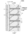
第1の実施の形態に係る補強構造1は、図1に示すように、既設のコンクリート部材(以下、単に「コンクリート部材」という場合がある)10に、コンクリート部材10の内面側から主鉄筋と交差する方向に形成された有底の補強部材挿入孔11の内部に配設されるせん断補強部材20と、前記補強部材挿入孔11に充填される充填材30とから構成されている。
As shown in FIG. 1, the reinforcing structure 1 according to the first embodiment is configured such that an existing concrete member (hereinafter sometimes simply referred to as “concrete member”) 10 is connected to a main reinforcing bar from the inner surface side of the
コンクリート部材10は、図1に示すように、所定の間隔により縦筋(主鉄筋)R1,R2および横筋(主鉄筋)R3,R4が配筋された鉄筋コンクリート造の部材である。なお、第1の実施の形態では、地下に埋設された既設の鉄筋コンクリート構造物の側壁(コンクリート部材10)を補強する場合について説明するが、補強を行う既設の鉄筋コンクリート構造物の構造体(コンクリート部材10)は側壁等の面材に限定されるものではなく、例えば床版(底版)、天井版(頂版)、梁、柱等であってもよい。また、既設のコンクリート部材10の設置箇所も限定されるものではない。また、第1の実施の形態では、コンクリート部材10として、鉄筋コンクリート部材を補強する場合について説明したが、コンクリート部材10は無筋コンクリート部材であってもよく、その形式は限定されるものではない。
As shown in FIG. 1, the
補強部材挿入孔11は、コンクリート部材10の内面側(地山Gと反対側の面)から外面側(地山G側の面)に向けて、せん断補強部材20を設置するために穿孔されたものであり、図2に示すように、コンクリート部材10の施工時の配筋図や非破壊試験の情報をもとに、穿孔時に縦筋(主筋)R1,R2及び横筋(主筋)R3,R4に損傷を与えることのないように、横間隔は縦筋R1,R2と、縦間隔は横筋R3,R4と同間隔で両鉄筋の中央に配置されている。図2(b)に示すように、補強部材挿入孔11の穿孔は、コンクリート部材10の内面側(一面側)から地盤Gと接している外面側(他面側)方向であってコンクリート部材10面に略垂直な方向に、インパクト・ドリルやロータリーハンマ・ドリル、コア・ドリルなどの穿孔手段を用いて、外面側の縦筋R1の位置近傍の深さまで行なわれている。また、補強部材挿入孔11の孔径は、図1に示すように、せん断補強部材20に取り付けられている突材22の外幅に若干の余裕を見込んだ値に形成されている。
The reinforcing
なお、補強部材挿入孔11は、せん断補強部材20の挿入時において、充填材30を充填する際に、内部の空気を排出しやすくするために、やや下向きの傾斜を有して形成し、当該充填材30の充填をより完全に行うことができるようにしてもよい。
The reinforcing
せん断補強部材20は、図3(a)に示すように、補強部材挿入孔11の延長よりも短い長さの棒材21と、この棒材21の軸方向に沿って所定の間隔を空けて配設される複数の突材22,22,…とにより構成されている。
本実施形態では、せん断補強部材20が、先端(地山G側の端部)が主筋R1,R3の近傍に位置し、また、基端(地山Gと反対側の端部)が、主筋R2,R4よりもコンクリート部材10の表面側に位置するように補強部材挿入孔11に挿入されている。
As shown in FIG. 3A, the
In the present embodiment, the
せん断補強部材20は、棒材21の外周囲に所定の間隔により配設された複数の突材22,22,…により、棒材21の周囲に複数の凸部が形成されている。
The
第1の実施の形態に係るせん断補強部材20は、図3(a)に示すように、棒材21がねじ鉄筋により構成されており、突材22が棒材21に螺合されるナットにより構成されている。
棒材21を構成する材料はねじ鉄筋に限定されるものではなく、その他の異形鉄筋や鋼棒等、コンクリート部材10のせん断補強に必要な耐力を有するものであれば、限定されるものではない。また、棒材21の断面寸法等も限定されるものではなく、適宜設定することが可能である。
As shown in FIG. 3A, the
The material constituting the
突材22は、棒材21への螺合が可能なナットにより構成されている。突材22は、棒材21の直径に対して110%乃至200%の外幅(外径)を有しており、ねじ鉄筋からなる棒材21に装着されることで、棒材21の周囲に凸部を形成している。本実施形態では、最も基端側(地山Gと反対側)の凸部が、横筋R4と同程度のコンクリート被りが確保できる位置に配置されている。
複数の突材22,22,…は、棒材21の略全長に亘って等間隔で配置された状態で、溶接等により固定されている。なお、突材22の固定方法は限定されるものではなく、例えば接着剤により固定してもよい。
The projecting
The plurality of projecting
充填材30には、上向きに充填しても流れ落ちることのない性質を有した可塑性のあるセメント系モルタルを用いる。ここで、可塑性のあるセメント系モルタルは、セメントとシリカヒュームや石英粉などのポゾラン物質と増粘材と水とから構成される材料である。なお、充填材30の材質等は、同様の特性を有するものであれば、これに限定されるものではない。
As the
第1の実施の形態に係る補強構造1の構築は、(1)補強部材挿入孔を穿孔する工程と、(2)せん断補強部材を挿入する工程と、の各工程により行う。 The construction of the reinforcing structure 1 according to the first embodiment is performed by the following steps: (1) a step of drilling a reinforcing member insertion hole, and (2) a step of inserting a shear reinforcing member.
(1)補強部材挿入孔を穿孔する工程
本工程は、コンクリート部材10である側壁の内側から外側(地山G側)に向けて、せん断補強部材20を設置するための補強部材挿入孔11を形成する作業を行う工程である。
(1) Step of drilling the reinforcing member insertion hole This step is for the reinforcing
図2(a)に示すように、補強部材挿入孔11は、コンクリート部材10の施工時の配筋図や非破壊試験の情報をもとに、穿孔時に縦筋R1,R2及び横筋R3,R4に損傷を与えることのないように、横間隔は縦筋R1,R2と、縦間隔は横筋R3,R4と同間隔で両鉄筋の中央に配置する。図2(b)に示すように、補強部材挿入孔11の穿孔は、コンクリート部材10の内側(一面側)から地盤Gと接している外側(他面側)方向であってコンクリート部材10面に略垂直な方向に、インパクト・ドリルやロータリーハンマ・ドリル、コア・ドリルなどの穿孔手段を用いて行う。
そして、補強部材挿入孔11の穿孔が完了したら、当該補強部材挿入孔10内に穿孔のために生じたコンクリート粉を除去する。
As shown in FIG. 2 (a), the reinforcing
When the drilling of the reinforcing
(2)せん断補強部材を挿入する工程
本工程は、補強部材挿入孔10にせん断補強部材20を挿入するとともに、当該補強部材挿入孔10に充填材30を注入して、一体化する作業を行う工程である。
(2) Step of inserting shear reinforcement member In this step, the
まず、補強部材挿入孔10にエポキシ樹脂、セメント系ミルクあるいはセメント系モルタルなどからなる充填材30を注入する。このとき、充填材30の注入量は、適宜設定すればよいが、第1の実施の形態では、せん断補強部材20を挿入した状態で補強部材挿入孔11内が充填される量とする。次に、せん断補強部材20を、補強部材挿入孔10に挿入する。なお、せん断補強部材20の挿入と充填材30の注入の順序はこれに限定されるものではなく、せん断補強部材20を補強部材挿入孔11に挿入した後に、せん断補強部材20と周囲の補強部材挿入孔10の内面の隙間に充填材30を充填してもよい。
First, a
以上、第1の実施の形態に係る補強構造1によれば、せん断補強部材20として棒材21の直径に対して110%乃至200%の幅を有する突材22により、異形鉄筋のふしに比べて大きな凸部が形成しているため、大きな定着効果を有している。そのため、従来のせん断補強部材と比較してより大きなコンクリート部材10のせん断補強効果を得ることを可能としている。
As described above, according to the reinforcing structure 1 according to the first embodiment, the
なお、前記実施形態では、棒材21に対して突材22を所定の間隔によりほぼ全長に配設するものとしたが、図3(b)に示すせん断補強部材20’のように、比較的付着力が大きな棒材21の中央部分については、突材22の配置を省略して直線区間としてもよい。
このように、突材22の設置を直線区間20a以外の凹凸区間20bのみに限定することで、突材22の材料費の削減およびせん断補強部材20’の製造時の手間を省略することで、費用の削減を図ることが可能となる。
In the above-described embodiment, the
In this way, by limiting the installation of the
また、せん断補強部材20は、充填材30を介してコンクリート部材10と一体化がなされているため、コンクリート部材10にせん断力Sが作用した際に、このせん断力Sをせん断補強部材20により受け持つことで、コンクリート部材10に発生する亀裂Cを抑制することが可能となる。
Further, since the
また、せん断補強部材20は、先端側に主筋R1,R3と同程度以上のコンクリート被りを確保しているため、何らかの原因で地山G側の表面のコンクリートが剥がれたとしても、定着長は確保しているため、せん断補強部材20による補強効果を維持することを可能としている。
一方、せん断補強部材20の基端側は、最も基端側の凸部が主筋R2,R4と同程度のコンクリート被りを確保できるように配置されていることで、何らかの原因により主筋R2,R4よりも表面側のコンクリートが剥がれたとしても、せん断補強部材20の定着は凸部により確保されているため、せん断補強部材20による補強効果が低下することがない。
In addition, since the
On the other hand, the base end side of the
なお、図1に示すように、第1の実施の形態では、せん断補強部材20を、せん断補強部材20の基端(地山Gと反対側の端部)が縦筋R2よりも表面側となるように配置しているが、せん断補強部材20の配置はこれに限定されるものではなく、縦筋R2または横筋R4と同程度のコンクリート被りを確保できる位置まで挿入してもよいことはいうまでもない。
また、第1の実施の形態では、せん断補強部材20の先端(地山G側の端部)を、縦筋R1よりも表面側に配置しているが、例えば、横筋R3と同等のコンクリート被りを確保できる深さまで挿入するなど、せん断耐力を増強させるために必要な長さを確保することができれば、せん断補強部材20の先端側の位置は限定されるものではない。
また、せん断補強部材20を横間隔は縦筋R1,R2と、縦間隔は横筋R3,R4と同間隔に配置するものとしたが、例えば、縦筋R1,R2または横筋R3,R4の配筋ピッチの2倍の間隔により配置するなど、せん断補強部材20の配置間隔は限定されるものではない。
As shown in FIG. 1, in the first embodiment, the
Moreover, in 1st Embodiment, although the front-end | tip (end part on the natural ground G side) of the
Further, the
<第2の実施の形態>
第2の実施の形態(参考実施形態)に係る補強構造2は、図4(a)に示すように、コンクリート部材10と、コンクリート部材10に形成された補強部材挿入孔11の内部に埋設されるせん断補強部材40と、補強部材挿入孔11に充填される充填材30とを有しており、このせん断補強部材40が、補強部材挿入孔11の延長よりも短い長さの棒材41と、この棒材41の外周面に巻き付けられる螺旋状の突材42とから構成されている点で、第1の実施の形態で示したせん断補強部材20と異なっている。
<Second Embodiment>
The reinforcing structure 2 according to the second embodiment (reference embodiment) is embedded in a
せん断補強部材40は、棒材41の外周囲に巻き付けられた螺旋状の突材42により、所定の間隔により形成された複数の凸部が、棒材41の周囲に形成されている。
In the
第2の実施の形態では、せん断補強部材40を構成する棒材41を、鋼棒により構成するものとするが、棒材41を構成する材料は、せん断補強部材として必要とされる強度を有した棒材であれば限定されるものではなく、例えば、異形鉄筋、ねじ鉄筋、鋼管等、適宜公知の材料から選定して使用すればよい。また、棒材41の断面寸法等も限定されるものではなく、適宜設定することが可能である。
In the second embodiment, the
突材42は、棒材41の直径の10%〜100%の直径を有するように構成されたワイヤーや番線の束等からなる。この突材42を棒材41の外周囲に巻き付ける事により、棒材21の直径に対して110%乃至200%の外幅(外径)を有した凸部を所定の間隔により形成している。
突材42は、棒材41に巻き付けられた状態で溶接や接着等により一体に固定されている。
The
The projecting
本実施形態では、せん断補強部材40を補強部材挿入孔11に配置した状態で、主筋R1,R3とR2,R4との間に突材42のほぼ全体が配置されるように構成されている。これにより、何らかの原因によりコンクリート被りが剥がれたとしても、せん断補強部材40はせん断補強に必要な定着を維持することが可能となる。
In the present embodiment, in the state where the
この他、第2の実施の形態に係る補強構造の構成は、第1の実施の形態で示した内容と同様なため、詳細な説明は省略する。 In addition, since the configuration of the reinforcing structure according to the second embodiment is the same as the content shown in the first embodiment, detailed description thereof is omitted.
以上、第2の実施の形態に係る補強構造2およびせん断補強部材40によれば、突材により複数の凸部がせん断補強部材40に形成されていることにより、大きな定着効果を奏する。そのため、従来のせん断補強部材と比較してより大きなコンクリート部材10のせん断補強効果を得ることを可能としている。
この他、第2の実施の形態に係るせん断補強部材40が配設された補強構造2は、第1の実施の形態に係る補強構造1と同様の作用効果を奏する。
As described above, according to the reinforcing structure 2 and the
In addition, the reinforcing structure 2 in which the
なお、第2の実施の形態では、棒材41に対して突材42をほぼ全長に巻き付けるものとしたが、図4(b)に示すせん断補強部材40’のように、比較的付着力が大きな棒材41の中央部分については、突材42の配置を省略して直線区間40aとしてもよい。
このように、突材42を直線区間40a以外の凹凸区間40bのみに限定することで、突材42の材料費の削減およびせん断補強部材40’の製造時の手間を省略し、費用の削減を図ることが可能となる。
In the second embodiment, the protruding
In this way, by limiting the projecting
また、突材42として、番線の束やワイヤーではなく、螺旋状の鋼棒や小径パイプを使用してもよい。
Further, as the projecting
<第3の実施の形態>
第3の実施の形態(参考実施形態)に係る補強構造3は、図5(a)に示すように、コンクリート部材10と、コンクリート部材10に形成された補強部材挿入孔11の内部に埋設されるせん断補強部材50と、補強部材挿入孔11に充填される充填材30とを有ており、せん断補強部材50が、線材を螺旋状に加工することで内径に対して外径が110%乃至200%となる部材である点で、第1の実施の形態で示した補強構造1と異なっている。
<Third Embodiment>
The reinforcing structure 3 according to the third embodiment (reference embodiment) is embedded in the
第3の実施の形態に係るせん断補強部材50は、鋼棒や小径パイプ等からなる線材を、この線材の直径に対して1倍〜10倍程度の直径により螺旋状に加工することにより構成されている。
この他、第3の実施の形態に係る補強構造3の構成は、第1の実施の形態に係る補強構造1の構成と同様なため、詳細な説明は省略する。
The
In addition, since the configuration of the reinforcing structure 3 according to the third embodiment is similar to the configuration of the reinforcing structure 1 according to the first embodiment, detailed description thereof is omitted.
以上、第3の実施の形態に係る補強構造3およびせん断補強部材50によれば、螺旋状に形成されたせん断補強部材50が、複数の凹凸が形成された棒材と同様に、大きな定着効果を有している。そのため、従来のせん断補強部材と比較してより大きなコンクリート部材10のせん断補強効果を得ることを可能としている。
この他、第3の実施の形態に係る補強構造3およびせん断補強部材50は、前記1の実施の形態に係る補強構造1およびせん断補強部材20と同様の作用効果を奏するため、詳細な説明は省略する。
As described above, according to the reinforcing structure 3 and the
In addition, since the reinforcing structure 3 and the
<第4の実施の形態>
第4の実施の形態(参考実施形態)に係る補強構造4は、コンクリート部材10と、コンクリート部材10に形成された補強部材挿入孔11の内部に埋設されるせん断補強部材60と、補強部材挿入孔11に充填される充填材30とを有しており、このせん断補強部材60が、補強部材挿入孔11の延長よりも短い長さからなり、外周面に複数の凹部62が形成された棒材61により構成されている点で、第1の実施の形態乃至第3の実施の形態の補強構造1乃至補強構造3と異なっている。
<Fourth embodiment>
The reinforcement structure 4 according to the fourth embodiment (reference embodiment) includes a
なお、せん断補強部材60は、図5(b)に示すように、棒材61に対して略全長に凹部62を形成してもいいし、図5(c)に示すせん断補強部材60’のように、比較的付着力が大きな棒材61の中央部分については、凹部62を省略して直線区間60aとしてもよい。
As shown in FIG. 5B, the
この他の第4の実施の形態に係る補強構造4およびせん断補強部材60に関する構成は、第1の実施の形態乃至第3の実施の形態で示した内容と同様なため、詳細な説明は省略する。
Since the configurations related to the reinforcing structure 4 and the
以上、第4の実施の形態に係る補強構造4およびせん断補強部材60によれば、せん断補強部材60に形成された複数の凹部62により、大きな定着効果が発現される。そのため、従来のせん断補強部材と比較してより大きなコンクリート部材10のせん断補強効果を得ることを可能としている。
この他、第4の実施の形態に係る補強構造4およびせん断補強部材60に関する作用効果は、第1の実施の形態乃至第3の実施の形態で示した内容と同様なため、詳細な説明は省略する。
As described above, according to the reinforcing structure 4 and the
In addition, since the operational effects relating to the reinforcing structure 4 and the
以上、本発明について、好適な実施形態について説明した。しかし、本発明は、前述の各実施形態に限られず、前記の各構成要素については、本発明の趣旨を逸脱しない範囲で、適宜設計変更が可能であることは言うまでもない。
例えば、補強対象である既設のコンクリート部材は、コンクリート造であればよく、現場打ち鉄筋コンクリート部材や、プレキャストコンクリート部材等その種類は問わないとともに、補強を行う部位についても限定されず、面材や版材等にも適用可能である。
また、せん断補強部材20の挿入間隔、挿入数、挿入位置等は、前記実施形態に限られず、適宜に定めることができる。
The preferred embodiments of the present invention have been described above. However, the present invention is not limited to the above-described embodiments, and it goes without saying that the above-described constituent elements can be appropriately changed in design without departing from the spirit of the present invention.
For example, the existing concrete member to be reinforced may be a concrete structure, and there is no limitation on the type such as a cast-in-place reinforced concrete member or a precast concrete member. It can also be applied to materials.
Further, the insertion interval, the number of insertions, the insertion position, and the like of the
また、前記各実施形態では、せん断補強部材について、同形状のものを所定の間隔により複数配置するものとしたが、コンクリート部材の形状や想定される作用応力の大きさや方向等に応じて、例えば、異なる形状のせん断補強部材を配置したり、せん断補強部材同士の間隔を変化させたりしてもよく、状況に応じて適宜変更することが可能である。 Further, in each of the above embodiments, a plurality of the same shape of the shear reinforcing member are arranged at a predetermined interval, but depending on the shape of the concrete member, the magnitude and direction of the assumed stress, etc., for example, Further, shear reinforcing members having different shapes may be arranged, or the interval between the shear reinforcing members may be changed, and can be appropriately changed depending on the situation.
1,2,3,4 補強構造
10 コンクリート部材
11 補強部材挿入孔
20,40,50,60 せん断補強部材
21,41,61 棒材
22,42 突材
30 充填材
1, 2, 3, 4
Claims (2)
前記補強部材挿入孔の延長よりも短い長さの棒材と、該棒材の軸方向に沿って所定の間隔を空けて当該棒材に固定される3つ以上の突材と、からなり、
前記突材が、前記棒材の周囲に3か所以上の凸部を形成し、該凸部の外幅が、前記棒材の直径に対して110%乃至200%であり、
最も基端側に形成された前記突材が、前記コンクリート部材の鉄筋と同程度のコンクリート被りが確保できる位置に配置されていることを特徴とするせん断補強部材。 A shear reinforcement member embedded in a reinforcement member insertion hole formed in an existing concrete member,
A rod having a length shorter than the extension of the reinforcing member insertion hole, and three or more projecting members fixed to the rod with a predetermined interval along the axial direction of the rod,
Wherein突材is the bar of the three or more protrusions formed around the outer width of the convex portion, Ri 110% to 200% der the diameter of the bar,
Most formed in said base end突材is the shear reinforcement member in which the overburden rebar and comparable concrete of the concrete member is characterized that you have been placed in a position that can be secured.
Priority Applications (1)
| Application Number | Priority Date | Filing Date | Title |
|---|---|---|---|
| JP2007302520A JP5654725B2 (en) | 2007-11-22 | 2007-11-22 | Shear reinforcement member |
Applications Claiming Priority (1)
| Application Number | Priority Date | Filing Date | Title |
|---|---|---|---|
| JP2007302520A JP5654725B2 (en) | 2007-11-22 | 2007-11-22 | Shear reinforcement member |
Publications (2)
| Publication Number | Publication Date |
|---|---|
| JP2009127261A JP2009127261A (en) | 2009-06-11 |
| JP5654725B2 true JP5654725B2 (en) | 2015-01-14 |
Family
ID=40818472
Family Applications (1)
| Application Number | Title | Priority Date | Filing Date |
|---|---|---|---|
| JP2007302520A Active JP5654725B2 (en) | 2007-11-22 | 2007-11-22 | Shear reinforcement member |
Country Status (1)
| Country | Link |
|---|---|
| JP (1) | JP5654725B2 (en) |
Families Citing this family (10)
| Publication number | Priority date | Publication date | Assignee | Title |
|---|---|---|---|---|
| JP2011140796A (en) * | 2010-01-07 | 2011-07-21 | Maeda Corp | Shear reinforcing structure for reinforced concrete structure |
| JP5525475B2 (en) * | 2011-03-30 | 2014-06-18 | 大成建設株式会社 | Reinforcement structure of existing reinforced concrete wall and reinforcement method of existing reinforced concrete wall |
| JP5611148B2 (en) * | 2011-08-22 | 2014-10-22 | 大成建設株式会社 | Shear reinforcement method and auxiliary device for reinforced concrete structure |
| JP5869832B2 (en) * | 2011-10-06 | 2016-02-24 | 前田建設工業株式会社 | Drilling method, shear reinforcing method, and drilling device for reinforced concrete structure |
| JP6094033B2 (en) * | 2012-01-20 | 2017-03-15 | 住友大阪セメント株式会社 | Shear reinforcement method for concrete structure using cartridge-based cementitious composition |
| JP2016169543A (en) * | 2015-03-13 | 2016-09-23 | 国立大学法人 東京大学 | Reinforcement structure and reinforcement method of reinforced concrete |
| DE102015213869A1 (en) * | 2015-07-22 | 2017-01-26 | Prof. Feix Research & Development Gmbh & Co. Kg | Reinforcing element for reinforcing a component, reinforcing arrangement comprising such a reinforcing element and method for reinforcing a component |
| JP7075748B2 (en) | 2017-12-07 | 2022-05-26 | 株式会社フジタ | Reinforcing bar |
| JP7058153B2 (en) * | 2018-03-22 | 2022-04-21 | 前田建設工業株式会社 | Maintenance method of concrete structure |
| JP7007674B2 (en) * | 2020-03-13 | 2022-02-10 | 国立大学法人 東京大学 | Reinforced structure and reinforcement method for reinforced concrete decks |
Family Cites Families (6)
| Publication number | Priority date | Publication date | Assignee | Title |
|---|---|---|---|---|
| JPS493895Y1 (en) * | 1969-09-01 | 1974-01-30 | ||
| JP3465186B2 (en) * | 2000-07-14 | 2003-11-10 | イビデングリーンテック株式会社 | Torsion reinforcing member for slope and ground reinforcement, and method of manufacturing the same |
| JP3932094B2 (en) * | 2001-10-04 | 2007-06-20 | 東日本旅客鉄道株式会社 | Method for reinforcing culvert structure |
| JP2004116084A (en) * | 2002-09-25 | 2004-04-15 | Ibiden Greentec Co Ltd | Reinforced concrete structure |
| JP4195686B2 (en) * | 2004-08-18 | 2008-12-10 | 大成建設株式会社 | Shear reinforcement structure |
| JP3668490B1 (en) * | 2004-08-18 | 2005-07-06 | 大成建設株式会社 | Shear force reinforcement structure |
-
2007
- 2007-11-22 JP JP2007302520A patent/JP5654725B2/en active Active
Also Published As
| Publication number | Publication date |
|---|---|
| JP2009127261A (en) | 2009-06-11 |
Similar Documents
| Publication | Publication Date | Title |
|---|---|---|
| JP5654725B2 (en) | Shear reinforcement member | |
| JP4472729B2 (en) | Reinforced structure | |
| WO2006018908A1 (en) | Shearing force reinforcing structure and shearing force reinforcing member | |
| JP4157510B2 (en) | Shear reinforcement structure | |
| JP5860576B2 (en) | Precast column beam connection structure | |
| KR101264396B1 (en) | Method for Reinforcing Earthquake-Resistant of Bridge Pier | |
| JP3700980B1 (en) | Shear force reinforcement method, shear force reinforcement structure, and shear reinforcement member | |
| JP5308012B2 (en) | Reinforcement structure for wall column members | |
| JP2005054532A (en) | Reinforcing structure of concrete structure, and method of reinforcing concrete structure | |
| JP2009174249A (en) | Reinforcing structure and reinforcing method | |
| JP5166837B2 (en) | Method for reinforcing wall structure and reinforcing structure | |
| JP2006016893A (en) | Shearing reinforcing method of existing structure | |
| JP2007146439A (en) | Precast member | |
| JP4195686B2 (en) | Shear reinforcement structure | |
| JP2012017575A (en) | Junction structure and junction method of precast concrete member | |
| JP2012102488A (en) | Seismic strengthening structure and seismic strengthening method for concrete skeleton | |
| JP5101050B2 (en) | Segment unit | |
| JP3676799B2 (en) | Shear force reinforcement method | |
| JP4515437B2 (en) | Method for producing filled steel pipe concrete column | |
| JP2006057290A5 (en) | ||
| JP3668490B1 (en) | Shear force reinforcement structure | |
| JP2009215789A (en) | Reinforcement structure | |
| JP4944521B2 (en) | Shear reinforcement structure, shear reinforcement method, and composite capsule for shear reinforcement | |
| JP5192724B2 (en) | Shear reinforcement method and filler filling method | |
| KR100661123B1 (en) | Concrete Pile with an Extended Head Using Reinforcing Plate |
Legal Events
| Date | Code | Title | Description |
|---|---|---|---|
| A621 | Written request for application examination |
Free format text: JAPANESE INTERMEDIATE CODE: A621 Effective date: 20101015 |
|
| A977 | Report on retrieval |
Free format text: JAPANESE INTERMEDIATE CODE: A971007 Effective date: 20120627 |
|
| A131 | Notification of reasons for refusal |
Free format text: JAPANESE INTERMEDIATE CODE: A131 Effective date: 20120703 |
|
| A521 | Request for written amendment filed |
Free format text: JAPANESE INTERMEDIATE CODE: A523 Effective date: 20120827 |
|
| A02 | Decision of refusal |
Free format text: JAPANESE INTERMEDIATE CODE: A02 Effective date: 20130416 |
|
| A521 | Request for written amendment filed |
Free format text: JAPANESE INTERMEDIATE CODE: A523 Effective date: 20130716 |
|
| A521 | Request for written amendment filed |
Free format text: JAPANESE INTERMEDIATE CODE: A821 Effective date: 20130719 |
|
| A911 | Transfer to examiner for re-examination before appeal (zenchi) |
Free format text: JAPANESE INTERMEDIATE CODE: A911 Effective date: 20130808 |
|
| A912 | Re-examination (zenchi) completed and case transferred to appeal board |
Free format text: JAPANESE INTERMEDIATE CODE: A912 Effective date: 20130823 |
|
| A521 | Request for written amendment filed |
Free format text: JAPANESE INTERMEDIATE CODE: A523 Effective date: 20141014 |
|
| A61 | First payment of annual fees (during grant procedure) |
Free format text: JAPANESE INTERMEDIATE CODE: A61 Effective date: 20141121 |
|
| R150 | Certificate of patent or registration of utility model |
Ref document number: 5654725 Country of ref document: JP Free format text: JAPANESE INTERMEDIATE CODE: R150 |
|
| R250 | Receipt of annual fees |
Free format text: JAPANESE INTERMEDIATE CODE: R250 |