JP5649121B2 - Packing box canopy device - Google Patents
Packing box canopy device Download PDFInfo
- Publication number
- JP5649121B2 JP5649121B2 JP2011049481A JP2011049481A JP5649121B2 JP 5649121 B2 JP5649121 B2 JP 5649121B2 JP 2011049481 A JP2011049481 A JP 2011049481A JP 2011049481 A JP2011049481 A JP 2011049481A JP 5649121 B2 JP5649121 B2 JP 5649121B2
- Authority
- JP
- Japan
- Prior art keywords
- canopy
- frame
- vehicle
- canopy frame
- side gate
- Prior art date
- Legal status (The legal status is an assumption and is not a legal conclusion. Google has not performed a legal analysis and makes no representation as to the accuracy of the status listed.)
- Active
Links
- 238000012856 packing Methods 0.000 title claims description 25
- 230000001105 regulatory effect Effects 0.000 claims 1
- 239000004576 sand Substances 0.000 description 4
- 238000010586 diagram Methods 0.000 description 2
- 239000000428 dust Substances 0.000 description 2
- 230000000694 effects Effects 0.000 description 2
- 125000002066 L-histidyl group Chemical group [H]N1C([H])=NC(C([H])([H])[C@](C(=O)[*])([H])N([H])[H])=C1[H] 0.000 description 1
- 238000009434 installation Methods 0.000 description 1
- 239000002184 metal Substances 0.000 description 1
- 230000002093 peripheral effect Effects 0.000 description 1
- 239000011347 resin Substances 0.000 description 1
- 229920005989 resin Polymers 0.000 description 1
- 230000000630 rising effect Effects 0.000 description 1
Images


Landscapes
- Lock And Its Accessories (AREA)
Description
本発明は、車両に架装された荷箱の上方開口部を開閉自在に覆う天蓋装置に関する。 The present invention relates to a canopy device that covers an upper opening of a cargo box mounted on a vehicle so as to be freely opened and closed.
ダンプカー等の車両の荷箱には、サイドゲートの上部に軸支された天蓋装置が設けられている。天蓋装置は、サイドゲート上端に設けられた軸受け部に例えば金属製の天蓋フレームが軸支された構成を有している。この天蓋フレームにはシート等が掛けられており、その軸支部を回動中心としてサイドゲートの外側方と内側方との間で回動される。天蓋フレームが閉状態の位置まで回動されると、シート等で荷箱の上方開口部の多くが覆われた状態になり、荷箱に積まれた土砂等の飛散を防止することができる。 A carton such as a dump truck is provided with a canopy device that is pivotally supported on an upper portion of a side gate. The canopy device has a configuration in which, for example, a metal canopy frame is pivotally supported on a bearing portion provided at the upper end of the side gate. A seat or the like is hung on the canopy frame, and the canopy frame is rotated between the outer side and the inner side of the side gate with the pivotal support portion as a rotation center. When the canopy frame is rotated to the closed position, most of the upper opening of the packing box is covered with a sheet or the like, and scattering of earth and sand loaded on the packing box can be prevented.
こうした天蓋装置を備えた車両の中でも、土砂等を大量に積載する比較的大型な車両は天蓋装置を構成するフレームの重量が大きくなる。フレームの回動は、サイドゲート上端を中心として、サイドゲート下方からサイドゲート上端を跨ぐようにして荷箱上方まで行われるため、電動モータ等の駆動力を利用した回動操作により、高い作業効率を有するものが多い(例えば、特許文献1)。 Among vehicles equipped with such a canopy device, a relatively large vehicle on which a large amount of earth and sand is loaded has a large frame weight. The frame is rotated from the lower side of the side gate to the upper side of the cargo box with the upper end of the side gate as the center, so that high work efficiency can be achieved by rotating operation using the driving force of an electric motor or the like. (For example, Patent Document 1).
その一方で、比較的小型で軽量な車両の場合、天蓋装置のフレーム重量が小さく、荷箱設置高さやサイドゲートの高さも低いため、手動でフレームの回動操作を行うことが可能となる。しかしながら、手動でフレームの回動操作を行う場合、フレームが荷箱の上方開口部を覆う閉状態のときには、閉状態を維持できるようにフレームの回動が規制されることが求められる。特に、フレーム重量が小さいため車両走行中に車両が上下に揺動すれば、フレームも同様に揺動して閉状態を維持できない恐れがある。 On the other hand, in the case of a relatively small and lightweight vehicle, the frame weight of the canopy device is small, and the height of the packing box installation and the side gate is low, so that the frame can be manually rotated. However, when manually rotating the frame, when the frame is in a closed state that covers the upper opening of the cargo box, it is required that the rotation of the frame be restricted so that the closed state can be maintained. In particular, since the frame weight is small, if the vehicle swings up and down while the vehicle is running, the frame may swing similarly and the closed state may not be maintained.
また、手動による回動操作の作業効率上、作業者がフレームの回動操作中は非ロック状態でなければならず、回動操作とは別にロック操作が必要となる。そのため、作業者がロック状態にすることを忘れてしまう恐れもある。 Further, in view of the work efficiency of the manual rotation operation, the operator must be in an unlocked state during the frame rotation operation, and a lock operation is required separately from the rotation operation. Therefore, there is a possibility that the operator forgets to set the locked state.
本発明は、これらの点を鑑みてなされており、手動で行う天蓋フレームの回動を規制することが可能であり、作業効率の低下を招くことのない荷箱の天蓋装置の提供を目的とする。 The present invention has been made in view of these points, and an object of the present invention is to provide a canopy device for a packing box that can regulate the rotation of the canopy frame that is manually performed and does not cause a reduction in work efficiency. To do.
上記の課題を解決するために次の構成とする。 In order to solve the above problems, the following configuration is adopted.
荷箱のサイドゲート上部に設けた軸受け部材と、当該軸受け部材に軸支された支軸と、当該支軸を有して前記サイドゲートの外側方と内側方との間で手動回動される荷箱の天蓋フレームと、前記サイドゲート上部に設けられて前記天蓋フレームの外側方又は内側方への少なくともいずれかの回動を手動で規制するロック装置と、を備えている荷箱の天蓋装置とする。前記天蓋フレームにシートやパネル等が配されることで、天蓋フレームを荷箱の上方開口部を覆うように閉状態とした際に、荷箱内の土砂や塵等の飛散を防止することができる。なお、本発明及び明細書における「天蓋フレームの閉状態」とは、前記天蓋フレームが荷箱の上方開口部を覆うように、サイドゲートの内側方に回動されて倒された状態を指しており、車両後方から見て、天蓋フレームが傾斜状態又は水平状態のいずれかに限定されるものではない。 A bearing member provided above the side gate of the cargo box, a support shaft supported by the bearing member, and manually rotated between the outer side and the inner side of the side gate having the support shaft. A canopy frame for a packing box, comprising: a canopy frame for the packing box; and a lock device that is provided at the upper part of the side gate and manually restricts rotation of at least one of the canopy frame toward the outside or the inside. And Sheets, panels, etc. are arranged on the canopy frame, so that when the canopy frame is closed so as to cover the upper opening of the packing box, scattering of earth and sand and dust in the packing box can be prevented. it can. In the present invention and specification, the “closed state of the canopy frame” refers to a state in which the canopy frame is turned inwardly of the side gate so as to cover the upper opening of the cargo box. The canopy frame is not limited to either the tilted state or the horizontal state when viewed from the rear of the vehicle.
前記ロック装置は、車両後方に付勢された係合部と、当該係合部を車両前方に移動操作するハンドルとを有し、前記天蓋フレームには、被係合部が配されており、前記天蓋フレームが閉状態のときに前記被係合部に前記係合部が係合される構成が好ましい。
さらに、前記係合部と前記被係合部との係合が解除された際、前記ハンドルは前記サイドゲートの外側方に突出している構成が好ましい。
前記ロック装置は、さらに前記サイドゲートにおける車両後方に設けられている。
The locking device includes an engaging portion biased to the rear of the vehicle, and a handle for moving the engaging portion to the front of the vehicle, and the engaged portion is disposed on the canopy frame. A configuration in which the engaging portion is engaged with the engaged portion when the canopy frame is closed is preferable.
Furthermore, it is preferable that the handle protrudes outward of the side gate when the engagement between the engaging portion and the engaged portion is released.
The locking device is further provided behind the vehicle at the side gate.
また、前記天蓋フレームの車両後方には、車両幅方向に回動可能な支持フレームが軸支されており、当該支持フレームの先端部には、前記荷箱のテールゲートの上縁部に係合するゲート係合部が設けられている構成としても良い。
以上の荷箱の天蓋装置のうち、前記テールゲートは前記サイドゲートよりも低く設定されている構成とすることもできる。
Further, a support frame that can be rotated in the vehicle width direction is pivotally supported on the rear side of the canopy frame, and is engaged with an upper edge portion of the tailgate of the cargo box at the front end portion of the support frame. It is good also as a structure provided with the gate engaging part to perform.
Of the above canopy canopies, the tailgate may be set lower than the side gate.
手動で天蓋フレームの回動操作を行う天蓋装置の場合、本発明のようにサイドゲート上部にロック装置を設けていることで、作業者は天蓋フレームの手動による回動操作を車両後方で行う際、作業者は荷箱の内方側に視線を向けやすいことから、サイドゲートの上部でかつ後方となる位置のロック装置は視野に入りやすく、ロック操作を忘れてしまうことを防止できる。 In the case of a canopy device that manually rotates the canopy frame, the lock device is provided on the upper side gate as in the present invention, so that the operator can manually rotate the canopy frame behind the vehicle. Since the operator can easily point his / her line of sight toward the inner side of the packing box, the locking device located at the upper part of the side gate and at the rear side can easily enter the field of view, thereby preventing the locking operation from being forgotten.
本発明に係る荷受台昇降装置について、図面を用いて実施形態の一例を説明する。 An example of an embodiment of a load receiving table lifting apparatus according to the present invention will be described with reference to the drawings.
図1(a)は本実施形態の荷箱10とその天蓋装置20とを示しており、車両を左側から見た側面図である。なお、説明の便宜上、天蓋装置20は、荷箱10における起立状態のサイドゲート1と同様に鉛直方向に沿って立ち上がった状態で示している。
Fig.1 (a) has shown the
荷箱10は、ダンプカー等の車両(不図示)に架装されており、車両前後方向に延びた車体枠上11で後ろ下がり状態に傾動自在な構成となっている。荷箱10は、車両後方端部(図中の右側端部)における下部にブラケット12を有しており、ブラケット12が車体枠11の後端部に対してピン13を介して軸支されている。また、図示はしないが、ブラケット12よりも前方側(図中の左側)で、荷箱10と車体枠11との間に傾動装置が配されている。この傾動装置は、周知の装置であり、油圧ポンプからの圧油により伸縮する油圧シリンダによって構成されている。油圧シリンダは、一端部が車体枠11に連結されて他端部が荷箱10に連結されており、油圧シリンダが伸長するとピン13を中心に荷箱10が傾動し、油圧シリンダが収縮すると荷箱10は水平状態に戻る。
The
荷箱10は、床面3に対して車両側方側で立設する左右一対のサイドゲート1と、車両後方側で立設するテールゲート2と、車両前方側で立設するフロントパネル(不図示)とで囲まれてなる構成を有する。
The
テールゲート2は床面3の後端部に設けられた下部ヒンジ21を中心として車両後方で矢印R1の方向に回動可能に構成されている。テールゲート2の高さは、図示のとおり、サイドゲート1よりも低く設定されており、車両後方から見て荷箱10には、テールゲート2の上方に後方開口部が形成されている。本実施形態に係る荷箱10は、その後端部が車体枠11の後端部と略一致するように架装されており、いわゆる軽自動車(道路運送車両法の施行規則で定められている軽自動車)仕様のものである。そのため、荷箱10の傾動中心となるピン2aまでの地上高も比較的低く、上述のようにテールゲート2の高さをサイドゲート1よりも低く設定することで矢印R1に沿って後方に回動(上開き)させた際に、上端部2bが地面に衝突することを防止できる。
サイドゲート1は、床面3に対して固定した状態で配されている。
The
The
天蓋装置20は、サイドゲート1の上端部で回動可能に軸支されており、所定の枠形状を有する天蓋フレーム21と、天蓋フレーム21に掛けられるシート22と、天蓋フレーム21をサイドゲート1に対して回動可能に軸支する軸受け部材23と、天蓋フレーム21の回動を規制するロック装置24とを有する構成である。この天蓋装置20は、天蓋フレーム21の一部がサイドゲート1に対して、ストッパ部材25を介して取り付けられている。
The
天蓋フレーム21は、車両前後方向に沿ってサイドゲート1と同程度の長さを有する。軸受け部材23はサイドゲート1の上端部に3つ配されている。天蓋フレーム21においてサイドゲート1に近接した位置に配された支軸21aが、軸受け部材23に軸支されており、天蓋フレーム21はサイドゲート1の外側方(図1紙面手前側)と内側方(図1紙面奥側)との間を回動可能となっている。本実施形態に係る天蓋フレーム21は、上述のとおり、軽自動車に架装される荷箱10に設けられる大きさなので、作業者が直接手で把持して回動させることができる程度の重量となっている。
The
シート22は、図示のとおり、天蓋フレーム21を覆う上方被覆部と、それ以外の後方被覆部とで形成されている。上方被覆部の端部には天蓋フレーム21に沿って複数の穴部211aが設けられている。図示は省略するが、紐をこれらの穴部211aに通して天蓋フレーム21に括り付けることで、シート22が天蓋フレーム21に掛けられている。なお、荷箱10の上方開口部を覆うように天蓋フレーム21を回動させた状態で、シート22の後方被覆部で荷箱10の後方開口部を覆うように、シート22(後方被覆部)を下方に張架させる。後方被覆部の張架は、端部に配されたゴム212等をテールゲート2の所定位置に設けられたフック(不図示)等に掛けることで行われる。シート22が荷箱10に対して掛けられることで、荷箱10の上方開口部や後方開口部から積み込まれた土砂や塵等の飛散を防止できる。
As illustrated, the
軸受け部材23はサイドゲート1の上端部に配された頂板23aに溶着されている。この頂板23aは車両前後方向に沿って見ると、L字状の断面形状を有しており、サイドゲート1の上面部全体を覆うように配されている。頂板23aには、車両前後方向に沿って、所定間隔だけ離れた2本の連結シャフト23bが溶着されている。
The bearing
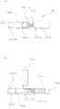
連結シャフト23bは、図1(b)及び図1(b)中となるA−A断面の図1(c)に示すように、サイドゲート1の外側面1aに設けられた筒状部材14に挿通されている。連結シャフト23bは、先端231bが筒状部材14から突出しており、その先端231bがストッパ部材25によってサイドゲート1に固定されている。ストッパ部材25は、断面凹形状のプレート25aと、このプレート25aに対して連結シャフト23bの先端231bを固定するボルト25b、ナット25cとで構成されている。
The connecting shaft 23b is connected to the
つまり、図2(a)で示すように、天蓋フレーム21は、支軸21aが軸受け部材23に軸支された状態で一体的にサイドゲート1に取り付けられる構成である。なお、図1中のストッパ部材25を解除することで、天蓋フレーム21等は簡単にサイドゲート1から取り外すことができる。また、取り付けることも簡単に行うことができる。
That is, as shown in FIG. 2A, the
また、天蓋フレーム21は、車両後方側(図2(a)中の右側)に支持フレーム26を有している。支持フレーム26は、基端部がピン26aを介して天蓋フレーム21の本体フレーム211に対して回動可能に軸支され、先端側に開口した略U字状のブラケット26bが配された構成となっている。車両後方から見ると、図2(b)のように支持フレーム26は、支軸21aを中心に回動する本体フレーム211の回動(矢印R2)とは別に、ピン26aを中心に回動可能となっている(矢印R3)。なお、図2(b)中の本体フレーム211のうち支軸側には、支持フレーム26の回動を規制するための樹脂製のストッパ(不図示)が設けられている。
The
矢印R2に沿って荷箱内方(サイドゲート1の内側方)側に回動されて閉状態となった天蓋フレーム21は、ロック装置24によってその回動が規制されて閉状態が維持される。ロック装置24は、図2(a)のとおり、車両後方側のサイドゲート1上端部に配されている。天蓋フレーム21が閉状態に回動されると、本体フレーム211の後方側に設けられた筒状の被係合部241とロック装置24とが略同じ高さとなって被係合部241と係合可能となる。このようにサイドゲート1の上部に配されたロック装置24は、作業者が回動操作時に注視する天蓋フレーム21の近傍に配されているので、作業者が目視し易い。特に、操作スペース上、天蓋フレーム21の回動操作を行い易い車両後方にロック装置24が配されているので、作業者は天蓋フレーム21の回動操作に引き続いて、その場でロック装置24の操作を行うことができる。
The
図3を用いてロック装置24を具体的に説明する。図3(a)は左側を車両前方側とするロック装置24の平面図で、図3(b)は車両左側から見たロック装置24の側面図である。ロック装置24は、車両前後方向に伸びる筒状カバー24aと、筒状カバー24aに内装されたシャフト24bと、バネ部材24cと、シャフト24bに取り付けられて筒状カバー24aに設けられた切欠き部241aから上方に突出したハンドル24dとを備えている。なお、バネ部材24cは、筒状カバー24aの内方端部に一端が固定されて、シャフト24bを車両前方側に付勢するように設けられている。切欠き部241aは、筒状カバー24aの上方側で車両前後方向を長手方向とする上方切欠き部2411aと、上方切欠き部2411aの後端部から筒状カバー24aの側方部にかけて形成された側方切欠き部2412aとを有する。
The locking
図3のロック装置24は、サイドゲート1の内側方に倒して閉状態とした際の被係合部241に対して、シャフト24bの先端部241bを車両前方に突出させて係合した状態である。反対に、閉状態の天蓋フレーム21を開状態とするため回動させる際には、ハンドル24dを把持し、バネ部材24cの付勢力に抗して車両後方にシャフト24bをスライドさせる。このとき、シャフト24bの先端部241bと被係合部241との係合状態が解除され、ハンドル24dを側方切欠き部2412aの領域に回転させることでロック装置24によるロック解除状態を維持することができる。筒状カバー24aと被係合部241とは、天蓋フレーム21が閉状態のとき、高さは略一致するが、車両後方から見て中心位置は車両幅方向に少しだけずれた状態となる。筒状カバー24aが被係合部241に対して荷箱内方側に位置していることで、シャフト24b外周面が被係合部241の内周面のうち荷箱内方側と当接し、天蓋フレーム21の起立方向への回動が規制される。ロック装置24による天蓋フレーム21の回動規制(ロック)は、ハンドル24dを車両前方にスライドさせるだけで良いので簡単である。
The locking
フロントパネル等で天蓋フレーム21の回動作業にスペースの点で制限がある車両前方側よりも、作業者が作業を行い易い車両後方側からロック装置24も視認し易く、天蓋フレーム21の回動作業後のロック装置24の操作も簡易であり、作業効率の面で大きな効果がある。また、側方切欠き部2412aの位置にハンドル24dが配されているときは、ハンドル24dがサイドゲート1の外側方に突出するので、天蓋フレーム21の回動が規制されていない(非ロック)状態であることを作業者が視認しやすい。
さらに、車両後方での作業において、本実施形態に係る天蓋装置20では次の効果も備えている。
The locking
Furthermore, the
天蓋装置20が閉状態のとき、荷箱10に対する天蓋フレーム21は車両後方から見て図4のようになっている。図4は、天蓋フレーム21と荷箱10とを示す模式図である。
When the
閉状態のとき、本体フレーム211は、支軸21aと軸受け部材との摩擦力により図4(a)の状態を維持している。このとき、支持フレーム26は、先端のU字状のブラケット26bがテールゲート上縁に係合されている。支持フレーム26は本体フレーム211に対して回動可能なので、本体フレーム211を良好に支持できる位置でブラケット26bをテールゲート上縁に係合させることができる。この係合は、車両後方側での天蓋フレーム21の回動作業の際に、作業者が本体フレーム211を把持しながら行うことができる。支持フレーム26によって本体フレーム211が良好に支持されていることで、比較的軽量な本体フレーム211がシート22に溜まる雨水やフレームの自重等で撓んでしまうことを防止できる。なお、図示する天蓋フレーム21の閉状態は、左右の天蓋フレーム21が車両後方から見ると山型に傾斜した状態となっているが、天蓋フレーム21が水平状態であっても、谷型形状であっても良い。また、天蓋フレーム21の傾斜角度も図示の状態に限定されず、車両や荷箱の大きさに適宜対応したものとし、支持フレーム26とテールゲート2との係合位置も適宜変更可能である。
In the closed state, the
また、荷箱10の後方開口部に対しては、上述のとおり、シート22を覆う(図1(a)参照)ので、同じ車両後方側で、「天蓋フレーム21の回動操作」、「テールゲート2に対する支持フレーム26の係合操作」、「ロック装置24による天蓋フレーム21の回動規制(ロック)」、及び「シート22による後方開口部の被覆作業」を一連の作業として行うことができ、作業効率の向上につながる。
In addition, as described above, the
また、支持フレーム26を用いれば、作業者の手動による天蓋フレーム21の回動作業を簡易化することもできる。図4(b)のように、天蓋フレーム21をサイドゲート1の外側方に向けて回動させる際、支持フレーム26を把持して持ち上げることで天蓋フレーム21の回動作業を行うことができる。特に本体フレーム211よりも低い位置で回動作業を開始させる場合、支持フレーム26の先端部付近を把持して回動させれば、本体フレーム211を把持する場合と比較して簡易となり好ましい。
Moreover, if the
支持フレーム26は本体フレーム211に対して回動可能なので、サイドゲート1とテールゲート2との高さの差(後方開口部の面積)が異なる場合でも適用できる。また、支持フレーム26の先端部のブラケット26bに関しても、支持本体フレーム26cにピン26dを介して軸支されている構成とすれば、支持フレーム26の延伸方向に対して回動自在となり好ましい。
上記の天蓋装置20は、以下の構成とすることも可能である。
Since the
The
例えば、軸受け部材23がサイドゲート1、例えばサイドゲート1の上縁部に溶着された構成とし、サイドゲート1に対して天蓋フレーム21が固着された構成としても良い。
For example, the bearing
ロック装置24に関しては、ロック操作及びロック解除操作のいずれか一方だけでも自動的に行われる構成としても良い。例えば、図5(a)に示すロック装置240としても良い。このロック装置240を用いる形態は、上述したロック装置24(図3参照)と比較して、切欠き部2410aの形状と、天蓋フレーム21後方に配された被係合部2410とが異なる。切欠き部2410aは、筒状カバー240aの延伸方向に延びる形状のみからなり、被係合部2410は下面にテーパ部2411を有するプレート部材となっている。天蓋フレーム21が回動して閉状態となる際、図5(b)で示すようにテーパ部2411がシャフト先端部241bに当接し、図中の一点鎖線部で示すようにシャフト24bを車両後方に移動させる。天蓋フレーム21が閉状態となったときには、被係合部2410はシャフト24bの下方に移動する。シャフト24bは、被係合部2410が下方に移動したときにはシャフト24bと非当接状態となり、バネ部材24cの付勢力によって車両前方に再度移動する(図中の実線部分)。つまり、天蓋フレーム21が閉状態となる際にはロック装置240は自動操作される。一方で、天蓋フレーム21を開状態にする際には、ハンドル24dを作業者が手動操作してシャフト24bを車両後方にスライドさせて、被係合部2410が回動できるようにする。このロック装置240の場合、閉状態のときには自動的に作動するため作業者の作業効率の向上につながり、開状態にするには別途手動操作がなければロック解除されないため、車両走行中に天蓋フレーム21が不意に回動することもなく安全である。
The
また、ロック装置24、240に関しては、サイドゲート1の上部であれば、上面に限らず、その近傍でも構わない。さらに、車両後端部に限らず、作業者の作業効率が低下しない範囲であれば、異なる場所に配しても構わない。特に軽自動車の場合、車両前後方向におけるサイドゲート1の長さも制限されるため、作業者が早期に操作できる場合には車両前方に設けていても構わない。
Further, the
その他、バネ部材24cによってシャフト24bが付勢される方向は車両後方となるものでも良い。また、その構成に関しても、荷箱10の上部に設けられて手動操作するものであれば、例えばフック形状の係合部が係合可能となるように移動するものでも良い。また、サイドゲート1とテールゲート2の高さに関しては、テールゲート2の方が高い構成も良いし、略一致する構成でも良い。サイドゲート1とテールゲート2との高さが略一致する場合であっても、支持フレーム26が配された構成でも良い。この場合、支持フレーム26をテールゲート2に係合させることで、天蓋フレーム21の閉状態時のサイドゲート1に対する傾斜角度を適宜調整することができる。
In addition, the direction in which the
なお、上述した荷箱10は、後ろ下がりに傾動操作されるダンプカー等に架装されるものとしたが、傾動装置を備えていない車両や軽自動車以外の車両等でも手動操作される天蓋装置が配されたものにも適用可能である。
The above-described
本発明は、車両に架装された全ての種類の荷箱に対して有用である。 The present invention is useful for all types of packing boxes mounted on vehicles.
1 サイドゲート
2 テールゲート
3 床面
10 荷箱
11 車体枠
20 天蓋装置
21 天蓋フレーム
22 シート
23 軸受け部材
24 ロック装置
25 ストッパ部材
26 支持フレーム
241 被係合部
21a 支軸
23a 頂板
23b 連結シャフト
24a 筒状カバー(筒状部材)
24b シャフト(係合部)
24c バネ部材
24d ハンドル
25a プレート(凹形状)
25b ボルト
25c ナット
26a ピン
26b ブラケット(ゲート係合部)
DESCRIPTION OF
24b Shaft (engagement part)
24c Spring member 24d Handle 25a Plate (concave shape)
25b Bolt 25c Nut 26a Pin 26b Bracket (Gate engaging part)
Claims (3)
Priority Applications (1)
| Application Number | Priority Date | Filing Date | Title |
|---|---|---|---|
| JP2011049481A JP5649121B2 (en) | 2011-03-07 | 2011-03-07 | Packing box canopy device |
Applications Claiming Priority (1)
| Application Number | Priority Date | Filing Date | Title |
|---|---|---|---|
| JP2011049481A JP5649121B2 (en) | 2011-03-07 | 2011-03-07 | Packing box canopy device |
Publications (3)
| Publication Number | Publication Date |
|---|---|
| JP2012183959A JP2012183959A (en) | 2012-09-27 |
| JP2012183959A5 JP2012183959A5 (en) | 2013-02-28 |
| JP5649121B2 true JP5649121B2 (en) | 2015-01-07 |
Family
ID=47014416
Family Applications (1)
| Application Number | Title | Priority Date | Filing Date |
|---|---|---|---|
| JP2011049481A Active JP5649121B2 (en) | 2011-03-07 | 2011-03-07 | Packing box canopy device |
Country Status (1)
| Country | Link |
|---|---|
| JP (1) | JP5649121B2 (en) |
Family Cites Families (5)
| Publication number | Priority date | Publication date | Assignee | Title |
|---|---|---|---|---|
| US10016A (en) * | 1853-09-13 | Bootjack | ||
| JPS55171645U (en) * | 1979-05-28 | 1980-12-09 | ||
| JPH03102338U (en) * | 1990-02-06 | 1991-10-24 | ||
| JP3146424U (en) * | 2008-09-04 | 2008-11-13 | 有限会社 アルファー精機 | Stopper bracket for cargo bed cover |
| JP2012051463A (en) * | 2010-09-01 | 2012-03-15 | Shinmaywa Industries Ltd | Motor truck |
-
2011
- 2011-03-07 JP JP2011049481A patent/JP5649121B2/en active Active
Also Published As
| Publication number | Publication date |
|---|---|
| JP2012183959A (en) | 2012-09-27 |
Similar Documents
| Publication | Publication Date | Title |
|---|---|---|
| JP2014012445A (en) | Vehicle with tailgate | |
| US20230174360A1 (en) | Forklift | |
| JP2008195348A (en) | Vehicle and working machine | |
| US9738204B1 (en) | Tailgate ramp apparatus | |
| KR20140140703A (en) | Structure for prevention collision of fork for forklift truck | |
| JP5649121B2 (en) | Packing box canopy device | |
| JP6215918B2 (en) | vehicle | |
| US7571952B1 (en) | Protection screen and truck equipped with it | |
| JP3370042B2 (en) | Work vehicle | |
| JP4933345B2 (en) | Dust input box for garbage truck | |
| JP6225177B2 (en) | vehicle | |
| JP3141384U (en) | Rear bumper storage device in dump truck | |
| JP6095772B2 (en) | vehicle | |
| JP5874650B2 (en) | Wheel crane | |
| JP2013203311A (en) | Bumper for dump truck | |
| JP6315012B2 (en) | Rear body structure of a car with retractable roof | |
| JP5684678B2 (en) | Work vehicle | |
| JP6114772B2 (en) | Rear bumper for asphalt finisher | |
| JP6323855B2 (en) | Multipurpose vehicle | |
| JP7224736B2 (en) | Freight vehicles with packing boxes and packing boxes that can be tilted to the side | |
| JP5832874B2 (en) | Packing box canopy device | |
| JP2012051463A (en) | Motor truck | |
| WO2016076141A1 (en) | Multipurpose vehicle | |
| JP2016094131A (en) | Multipurpose vehicle | |
| JP3182372U (en) | Lorry |
Legal Events
| Date | Code | Title | Description |
|---|---|---|---|
| A521 | Request for written amendment filed |
Free format text: JAPANESE INTERMEDIATE CODE: A523 Effective date: 20130109 |
|
| A621 | Written request for application examination |
Free format text: JAPANESE INTERMEDIATE CODE: A621 Effective date: 20131017 |
|
| A977 | Report on retrieval |
Free format text: JAPANESE INTERMEDIATE CODE: A971007 Effective date: 20140717 |
|
| A131 | Notification of reasons for refusal |
Free format text: JAPANESE INTERMEDIATE CODE: A131 Effective date: 20140819 |
|
| A521 | Request for written amendment filed |
Free format text: JAPANESE INTERMEDIATE CODE: A523 Effective date: 20140922 |
|
| TRDD | Decision of grant or rejection written | ||
| A01 | Written decision to grant a patent or to grant a registration (utility model) |
Free format text: JAPANESE INTERMEDIATE CODE: A01 Effective date: 20141105 |
|
| A61 | First payment of annual fees (during grant procedure) |
Free format text: JAPANESE INTERMEDIATE CODE: A61 Effective date: 20141106 |
|
| R150 | Certificate of patent or registration of utility model |
Ref document number: 5649121 Country of ref document: JP Free format text: JAPANESE INTERMEDIATE CODE: R150 |
|
| R250 | Receipt of annual fees |
Free format text: JAPANESE INTERMEDIATE CODE: R250 |
|
| R250 | Receipt of annual fees |
Free format text: JAPANESE INTERMEDIATE CODE: R250 |
|
| R250 | Receipt of annual fees |
Free format text: JAPANESE INTERMEDIATE CODE: R250 |
|
| R250 | Receipt of annual fees |
Free format text: JAPANESE INTERMEDIATE CODE: R250 |
|
| R250 | Receipt of annual fees |
Free format text: JAPANESE INTERMEDIATE CODE: R250 |
|
| R250 | Receipt of annual fees |
Free format text: JAPANESE INTERMEDIATE CODE: R250 |
|
| R250 | Receipt of annual fees |
Free format text: JAPANESE INTERMEDIATE CODE: R250 |