JP5649108B2 - Puncture needle for bone cement injection - Google Patents
Puncture needle for bone cement injection Download PDFInfo
- Publication number
- JP5649108B2 JP5649108B2 JP2010052300A JP2010052300A JP5649108B2 JP 5649108 B2 JP5649108 B2 JP 5649108B2 JP 2010052300 A JP2010052300 A JP 2010052300A JP 2010052300 A JP2010052300 A JP 2010052300A JP 5649108 B2 JP5649108 B2 JP 5649108B2
- Authority
- JP
- Japan
- Prior art keywords
- needle
- outer needle
- bone
- inner tube
- bone cement
- Prior art date
- Legal status (The legal status is an assumption and is not a legal conclusion. Google has not performed a legal analysis and makes no representation as to the accuracy of the status listed.)
- Expired - Fee Related
Links
Images


Classifications
-
- A—HUMAN NECESSITIES
- A61—MEDICAL OR VETERINARY SCIENCE; HYGIENE
- A61B—DIAGNOSIS; SURGERY; IDENTIFICATION
- A61B17/00—Surgical instruments, devices or methods, e.g. tourniquets
- A61B17/56—Surgical instruments or methods for treatment of bones or joints; Devices specially adapted therefor
- A61B17/58—Surgical instruments or methods for treatment of bones or joints; Devices specially adapted therefor for osteosynthesis, e.g. bone plates, screws, setting implements or the like
- A61B17/88—Osteosynthesis instruments; Methods or means for implanting or extracting internal or external fixation devices
- A61B17/8802—Equipment for handling bone cement or other fluid fillers
- A61B17/8805—Equipment for handling bone cement or other fluid fillers for introducing fluid filler into bone or extracting it
- A61B17/8816—Equipment for handling bone cement or other fluid fillers for introducing fluid filler into bone or extracting it characterised by the conduit, e.g. tube, along which fluid flows into the body or by conduit connections
-
- A—HUMAN NECESSITIES
- A61—MEDICAL OR VETERINARY SCIENCE; HYGIENE
- A61B—DIAGNOSIS; SURGERY; IDENTIFICATION
- A61B17/00—Surgical instruments, devices or methods, e.g. tourniquets
- A61B17/34—Trocars; Puncturing needles
-
- A—HUMAN NECESSITIES
- A61—MEDICAL OR VETERINARY SCIENCE; HYGIENE
- A61B—DIAGNOSIS; SURGERY; IDENTIFICATION
- A61B17/00—Surgical instruments, devices or methods, e.g. tourniquets
- A61B17/56—Surgical instruments or methods for treatment of bones or joints; Devices specially adapted therefor
-
- A—HUMAN NECESSITIES
- A61—MEDICAL OR VETERINARY SCIENCE; HYGIENE
- A61B—DIAGNOSIS; SURGERY; IDENTIFICATION
- A61B17/00—Surgical instruments, devices or methods, e.g. tourniquets
- A61B17/56—Surgical instruments or methods for treatment of bones or joints; Devices specially adapted therefor
- A61B17/58—Surgical instruments or methods for treatment of bones or joints; Devices specially adapted therefor for osteosynthesis, e.g. bone plates, screws, setting implements or the like
- A61B17/88—Osteosynthesis instruments; Methods or means for implanting or extracting internal or external fixation devices
- A61B17/8802—Equipment for handling bone cement or other fluid fillers
- A61B17/8805—Equipment for handling bone cement or other fluid fillers for introducing fluid filler into bone or extracting it
- A61B17/8819—Equipment for handling bone cement or other fluid fillers for introducing fluid filler into bone or extracting it characterised by the introducer proximal part, e.g. cannula handle, or by parts which are inserted inside each other, e.g. stylet and cannula
-
- A—HUMAN NECESSITIES
- A61—MEDICAL OR VETERINARY SCIENCE; HYGIENE
- A61B—DIAGNOSIS; SURGERY; IDENTIFICATION
- A61B17/00—Surgical instruments, devices or methods, e.g. tourniquets
- A61B17/56—Surgical instruments or methods for treatment of bones or joints; Devices specially adapted therefor
- A61B17/58—Surgical instruments or methods for treatment of bones or joints; Devices specially adapted therefor for osteosynthesis, e.g. bone plates, screws, setting implements or the like
- A61B17/88—Osteosynthesis instruments; Methods or means for implanting or extracting internal or external fixation devices
- A61B17/8802—Equipment for handling bone cement or other fluid fillers
- A61B17/8805—Equipment for handling bone cement or other fluid fillers for introducing fluid filler into bone or extracting it
- A61B17/8827—Equipment for handling bone cement or other fluid fillers for introducing fluid filler into bone or extracting it with filtering, degassing, venting or pressure relief means
-
- A—HUMAN NECESSITIES
- A61—MEDICAL OR VETERINARY SCIENCE; HYGIENE
- A61F—FILTERS IMPLANTABLE INTO BLOOD VESSELS; PROSTHESES; DEVICES PROVIDING PATENCY TO, OR PREVENTING COLLAPSING OF, TUBULAR STRUCTURES OF THE BODY, e.g. STENTS; ORTHOPAEDIC, NURSING OR CONTRACEPTIVE DEVICES; FOMENTATION; TREATMENT OR PROTECTION OF EYES OR EARS; BANDAGES, DRESSINGS OR ABSORBENT PADS; FIRST-AID KITS
- A61F2/00—Filters implantable into blood vessels; Prostheses, i.e. artificial substitutes or replacements for parts of the body; Appliances for connecting them with the body; Devices providing patency to, or preventing collapsing of, tubular structures of the body, e.g. stents
- A61F2/02—Prostheses implantable into the body
- A61F2/28—Bones
-
- A—HUMAN NECESSITIES
- A61—MEDICAL OR VETERINARY SCIENCE; HYGIENE
- A61M—DEVICES FOR INTRODUCING MEDIA INTO, OR ONTO, THE BODY; DEVICES FOR TRANSDUCING BODY MEDIA OR FOR TAKING MEDIA FROM THE BODY; DEVICES FOR PRODUCING OR ENDING SLEEP OR STUPOR
- A61M5/00—Devices for bringing media into the body in a subcutaneous, intra-vascular or intramuscular way; Accessories therefor, e.g. filling or cleaning devices, arm-rests
- A61M5/14—Infusion devices, e.g. infusing by gravity; Blood infusion; Accessories therefor
- A61M5/158—Needles for infusions; Accessories therefor, e.g. for inserting infusion needles, or for holding them on the body
- A61M2005/1587—Needles for infusions; Accessories therefor, e.g. for inserting infusion needles, or for holding them on the body suitable for being connected to an infusion line after insertion into a patient
Landscapes
- Health & Medical Sciences (AREA)
- Life Sciences & Earth Sciences (AREA)
- Surgery (AREA)
- Orthopedic Medicine & Surgery (AREA)
- Biomedical Technology (AREA)
- Engineering & Computer Science (AREA)
- Heart & Thoracic Surgery (AREA)
- Animal Behavior & Ethology (AREA)
- General Health & Medical Sciences (AREA)
- Public Health (AREA)
- Veterinary Medicine (AREA)
- Nuclear Medicine, Radiotherapy & Molecular Imaging (AREA)
- Medical Informatics (AREA)
- Molecular Biology (AREA)
- Physics & Mathematics (AREA)
- Fluid Mechanics (AREA)
- Vascular Medicine (AREA)
- Anesthesiology (AREA)
- Hematology (AREA)
- Pathology (AREA)
- Cardiology (AREA)
- Oral & Maxillofacial Surgery (AREA)
- Transplantation (AREA)
- Surgical Instruments (AREA)
- Dental Tools And Instruments Or Auxiliary Dental Instruments (AREA)
- Prostheses (AREA)
- Media Introduction/Drainage Providing Device (AREA)
- Infusion, Injection, And Reservoir Apparatuses (AREA)
Description
本発明は、骨セメントを骨の内部に注入するための穿刺針に関する。 The present invention relates to a puncture needle for injecting bone cement into a bone.
経皮的椎体形成術は、椎体圧迫骨折による痛みを除去するために、骨セメントを椎体の損傷部位に注入して椎体を補強する治療法である。経皮的椎体形成術は、1987年フランスで初めて行われた比較的新しい治療法であるが、近年わが国においても多くの施設で行われている。 Percutaneous vertebroplasty is a treatment that reinforces the vertebral body by injecting bone cement into the vertebral body injury site in order to eliminate pain caused by vertebral body compression fractures. Percutaneous vertebroplasty is a relatively new treatment performed for the first time in France in 1987, but in recent years it has been performed in many facilities in Japan.
経皮的椎体形成術は、椎体の背側左右に位置する椎弓根から中空構造の穿刺針を穿刺して、穿刺針内の注入通路を介して椎体内に骨セメントを注入する椎弓根アプローチ(trans pedicular approach)が基本である。骨セメントを注入するための穿刺針としては、骨生検針が一般的に用いられている(例えば、下記特許文献1を参照)。椎弓根アプローチには、左右両側から穿刺する2針法と、片側のみから穿刺する1針法とがある。1針法は、2針法と比較して経費削減、合併症の軽減、被爆量の削減、手技施行時間の短縮が図れるという利点があるため、より好ましい穿刺方法であると考えられている。 In percutaneous vertebroplasty, a hollow puncture needle is punctured from the pedicle located on the left and right sides of the vertebral body, and bone cement is injected into the vertebral body through an injection passage in the puncture needle. The pedicle approach is fundamental. A bone biopsy needle is generally used as a puncture needle for injecting bone cement (see, for example, Patent Document 1 below). The pedicle approach includes a two-needle method of puncturing from both the left and right sides and a one-needle method of puncturing from only one side. The one-needle method is considered to be a more preferable puncture method because it has the advantages of reducing costs, reducing complications, reducing the amount of exposure, and shortening the procedure execution time compared to the two-needle method.
しかしながら、従来の穿刺針には、1針法により骨セメントを注入すると骨セメントが骨外に漏出する可能性があるという問題があった。 However, the conventional puncture needle has a problem that bone cement may leak out of the bone when the bone cement is injected by the single needle method.
すなわち、従来の穿刺針を用いて1針法により骨セメントを注入すると、骨セメントの注入に伴い骨内の内圧が高まるため、骨セメントが骨外(例えば、脊柱管腔内や静脈内)に漏出してしまう可能性があった。したがって、患者及び術者の両方に好ましい1針法の利点よりも内圧上昇の問題を回避することを重視して、一方の針を用いて骨内の内圧を減圧しうる2針法により手技を行うことが推奨されていた。 That is, when bone cement is injected by a single needle method using a conventional puncture needle, the internal pressure in the bone increases with the injection of the bone cement, so that the bone cement is outside the bone (for example, in the spinal canal or in the vein). There was a possibility of leakage. Therefore, emphasizing avoiding the problem of increased internal pressure rather than the advantage of the one-needle method preferable for both the patient and the operator, the procedure is performed by the two-needle method that can reduce the internal pressure in the bone using one needle. It was recommended to do.
本発明は、上記の事情に鑑みてなされたものであり、1針法でも骨内の内圧を高めることなく骨セメントを骨内に注入することができる骨セメント注入用穿刺針を提供することを目的とする。 The present invention has been made in view of the above circumstances, and provides a puncture needle for injecting bone cement that can inject bone cement into bone without increasing the internal pressure in the bone even with a single needle method. Objective.
本発明の骨セメント注入用穿刺針は、基端部近傍の側面に基端側孔部が設けられた中空構造の外針と、前記外針の基端部に固定され、前記外針の基端開口と連通する第1ポートを有する外針ハブと、先端に針先が設けられ、且つ前記外針及び前記第1ポートに挿通可能な内針と、前記内針の基端部に固定され、前記外針ハブに着脱可能な内針ハブと、前記外針及び前記第1ポートに挿通可能な内管と、前記内管の基端部に固定され、前記外針ハブに着脱可能であり、前記内管の基端開口と連通する第2ポートを有する内管ハブと、を備え、前記外針に前記内管が挿通され且つ前記外針が骨に穿刺された状態において、前記骨内と前記基端側孔部とを連通する流路が前記外針と前記内管との間に形成される、ことを特徴とする。 The puncture needle for bone cement injection according to the present invention includes a hollow outer needle having a proximal end side hole provided on a side surface in the vicinity of the proximal end portion, and is fixed to the proximal end portion of the outer needle. An outer needle hub having a first port communicating with the end opening, an inner needle that is provided with a needle tip at the distal end and can be inserted into the outer needle and the first port, and is fixed to a proximal end portion of the inner needle An inner needle hub that can be attached to and detached from the outer needle hub, an inner tube that can be inserted into the outer needle and the first port, and a base end portion of the inner tube that is detachable from the outer needle hub . An inner tube hub having a second port communicating with the proximal end opening of the inner tube, and the inner tube is inserted into the outer needle and the outer needle is pierced into the bone. And a passage that communicates with the base end side hole is formed between the outer needle and the inner tube.
上記の構成によれば、外針に内針を挿入した状態で外針及び内針の先端部を目的の骨に穿刺した後、外針から内針を抜去し、次に外針に内管を挿入すると、外針と内管とにより2重管構造が構成される。そして、外針には基端側孔部が設けられ、外針に内管が挿通され且つ外針が骨に穿刺された状態では、骨内と基端側孔部とを連通する流路が外針と内管との間に形成される。これにより、骨セメントを骨内に注入したとき、骨内の気体又は液体(例えば、浸出液や血液など)が外針と内管との間の流路を流れて、基端側孔部から体外に出ることが可能であるため、骨セメントの注入による骨内の内圧の上昇が防止され、この結果、骨セメントが骨外に漏出することを防止することができる。ここで、外針を内管と外管とからなる2重管構造とし、内管の中空部に内針が挿通される構成とすることも考えられるが、当該構成の場合、内管がある分、内針を大径化しにくい。これに対し、本発明では、内管を抜いた外針に内針を挿入する構成を採用したため、内管がない分、内針を大径化しやすく、穿刺及び抜去に必要な強度を容易に得ることが可能である。 According to the above configuration, after inserting the outer needle and the tip of the inner needle into the target bone with the inner needle inserted into the outer needle, the inner needle is removed from the outer needle, and then the inner needle is inserted into the outer needle. Is inserted, a double tube structure is constituted by the outer needle and the inner tube. Then, the outer needle is provided with a proximal end side hole, and in a state where the inner tube is inserted through the outer needle and the outer needle is punctured into the bone, a flow path that connects the inside of the bone and the proximal end side hole is provided. It is formed between the outer needle and the inner tube. As a result, when bone cement is injected into the bone, the gas or liquid in the bone (for example, exudate or blood) flows through the flow path between the outer needle and the inner tube, and from the proximal hole to the outside of the body. Therefore, the increase of internal pressure in the bone due to the injection of the bone cement is prevented, and as a result, the bone cement can be prevented from leaking out of the bone. Here, it is conceivable that the outer needle has a double tube structure composed of an inner tube and an outer tube, and the inner needle is inserted through the hollow portion of the inner tube. Minute, it is difficult to increase the diameter of the inner needle. On the other hand, in the present invention, since the configuration in which the inner needle is inserted into the outer needle with the inner tube removed is employed, the inner needle is easily increased in diameter due to the absence of the inner tube, and the strength necessary for puncturing and removal is easily achieved. It is possible to obtain.
前記外針は、先端部近傍の側面に先端側孔部を有し、前記外針に前記内管が挿通された状態で前記先端側孔部と前記基端側孔部とを連通する減圧通路が前記外針と前記内管との間に形成されるとよい。 The outer needle has a distal end side hole portion on a side surface near the distal end portion, and communicates the distal end side hole portion and the proximal end side hole portion with the inner tube inserted through the outer needle. Is preferably formed between the outer needle and the inner tube.
上記の構成によれば、簡単な構成で、骨内と基端側孔部とを連通する構造を実現できる。すなわち、当該構成によれば、外針に設けられた先端側孔部を介して、外針と内管との間の減圧通路と骨内とが連通するので、外針が骨に穿刺され且つ外針に内管が挿入された状態で骨セメントが骨内に注入されると、骨内の気体又は液体は、先端側孔部から外針と内管の間の減圧通路に流入し、減圧通路を流れて基端側孔部から流出する。 According to said structure, the structure which connects the inside of a bone | frame and a base end side hole part by simple structure is realizable. That is, according to the configuration, the decompression passage between the outer needle and the inner tube communicates with the bone through the distal end side hole provided in the outer needle, so that the outer needle is pierced into the bone and When bone cement is injected into the bone with the inner tube inserted in the outer needle, the gas or liquid in the bone flows into the decompression passage between the outer needle and the inner tube from the distal side hole, and the pressure is reduced. It flows through the passage and flows out from the base end side hole.
前記内管ハブを前記外針ハブに装着した状態で、前記内管の最先端部は、前記外針の最先端部と同じ位置か又は前記外針から突出するとよい。 While wearing the inner tube hub to the outer needle hub, the most distal portion of the inner tube, it is preferable to protrude from the outer needle cutting edge portion at the same position or the outer needle.
上記の構成によれば、内管の先端から出た骨セメントが外針内に付着しないので、内管を抜去した後に、外針への内針の再挿入を確実に行うことが可能である。また、骨セメントが外針内に付着しないことから、内針を外針に再挿入しても骨セメントが骨内に押し込まれることがない。すなわち、骨内に必要以上に骨セメントが注入されることが防止されることから、骨セメントを正確な注入量で骨内に注入することが可能となる。 According to the above configuration, since the bone cement that has come out from the tip of the inner tube does not adhere to the outer needle, it is possible to reliably reinsert the inner needle into the outer needle after removing the inner tube. . Further, since the bone cement does not adhere to the outer needle, even if the inner needle is reinserted into the outer needle, the bone cement is not pushed into the bone. That is, since the bone cement is prevented from being injected more than necessary into the bone, the bone cement can be injected into the bone with an accurate injection amount.
前記外針に前記内管が挿通された状態で、前記外針の最先端部で開口する減圧通路が前記外針と前記内管との間に形成されるとよい。 In a state where the inner tube is inserted through the outer needle, a decompression passage that opens at the most distal end portion of the outer needle may be formed between the outer needle and the inner tube.
上記の構成によれば、簡単な構成で、骨内と基端側孔部とを連通する構造を実現できる。すなわち、当該構成によれば、外針の最先端部で開口する減圧通路が外針と内管との間に形成されるので、外針が骨に穿刺され且つ外針に内管が挿入された状態で骨セメントが骨内に注入されると、骨内の気体又は液体は、外針の最先開口から外針と内管の間の減圧通路に流入し、減圧通路を流れて基端側孔部から流出する。 According to said structure, the structure which connects the inside of a bone | frame and a base end side hole part by simple structure is realizable. That is, according to this configuration, since the decompression passage that opens at the most distal end portion of the outer needle is formed between the outer needle and the inner tube, the outer needle is punctured into the bone and the inner tube is inserted into the outer needle. When the bone cement is injected into the bone in a state of being in a state, the gas or liquid in the bone flows into the decompression passage between the outer needle and the inner tube from the earliest opening of the outer needle, and flows through the decompression passage to the proximal end. It flows out from the side hole.
前記外針に前記内管が挿通された状態で、前記内管の先端部は、前記外針の先端部から突出するとよい。 In a state where the inner tube is inserted through the outer needle, the distal end portion of the inner tube may protrude from the distal end portion of the outer needle.
上記の構成によれば、画像誘導下(X線透視下又はCT透視下)において、内管の先端部と、外針の先端部との段差がマーカーとなる。すなわち、当該段差が画像上で視覚的に認識しやすいため、外針の骨内への穿刺を簡単且つ確実に行うことが可能となる。また、内管の先端から出た骨セメントが外針内に付着しないので、内管を抜去した後に、外針への内針の再挿入を確実に行うことが可能である。さらに、骨セメントが外針内に付着しないことから、内針を外針に再挿入しても骨内には骨セメントが押し込まれることがない。すなわち、骨内に必要以上に骨セメントが注入されることが防止されることから、骨内へ骨セメントを正確な注入量で注入することが可能となる。また、上記の骨セメント注入用穿刺針において、前記基端側孔部は、前記外針ハブ内に位置するとともに、前記外針ハブに設けられた第3ポートと連通するとよい。 According to the above configuration, the step between the distal end portion of the inner tube and the distal end portion of the outer needle becomes a marker under image guidance (under fluoroscopy or CT fluoroscopy). That is, since the step is easily visually recognized on the image, the outer needle can be punctured into the bone easily and reliably. Further, since the bone cement coming out from the tip of the inner tube does not adhere to the outer needle, it is possible to reliably insert the inner needle into the outer needle after removing the inner tube. Further, since bone cement does not adhere to the outer needle, even if the inner needle is reinserted into the outer needle, the bone cement is not pushed into the bone. That is, since it is prevented that the bone cement is injected more than necessary into the bone, the bone cement can be injected into the bone with an accurate injection amount. In the bone cement injection puncture needle, the proximal hole may be located in the outer needle hub and communicate with a third port provided in the outer needle hub.
本発明に係る骨セメント注入用穿刺針によれば、1針法でも骨内の内圧を高めることなく骨セメントを骨内に注入することができる。 According to the puncture needle for injecting bone cement according to the present invention, bone cement can be injected into the bone without increasing the internal pressure in the bone even with the single needle method.
以下、本発明に係る骨セメント注入用穿刺針について好適な実施の形態を挙げ、添付の図面を参照しながら説明する。なお、本明細書において「骨セメント」には、骨セメント(プラスチック製剤など)だけでなく骨ペースト(リン酸カルシウム製剤など)も含まれるものとする。 Hereinafter, preferred embodiments of a bone cement injection puncture needle according to the present invention will be described with reference to the accompanying drawings. In the present specification, “bone cement” includes not only bone cement (plastic preparation and the like) but also bone paste (calcium phosphate preparation and the like).
[第1実施形態]
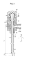
図1は、本発明の第1の実施形態に係る骨セメント注入用穿刺針10(以下、「穿刺針10」という)の全体構成図である。図1に示すように、穿刺針10は、中空構造の外針12と、外針12の基端部に固定された外針ハブ14と、外針12の中空部に挿通可能な内針16と、内針16の基端部に固定された内針ハブ18と、外針12の中空部に挿通可能な内管17と、内管17の基端部に固定された内管ハブ19とを有する。図1では、外針12に内針16が挿入され、外針12から内管17が抜去された状態を示している。
[First Embodiment]
FIG. 1 is an overall configuration diagram of a bone cement injection puncture needle 10 (hereinafter referred to as “
なお、以下の説明では、内針16及び外針12の軸心方向をZ方向とし、Z方向に垂直な方向をX方向とし、Z方向及びX方向に垂直な方向をY方向とする。図1では、X方向は、Z方向に垂直且つ紙面に平行な方向であり、Y方向は、紙面に垂直な方向である。Z方向のうち、特に、穿刺針10の先端側に向かう方向をZ1とし、穿刺針10の基端側に向かう方向をZ2とする。
In the following description, the axial direction of the
図2は、図1のII−II線での一部省略断面図である。図2に示すように、外針12は、両端が開口した中空構造の部材であり、例えば、中空円筒管の形態をとり得る。外針12の中空部20には内針16が挿入可能である。外針12の長さは、90〜200mm程度である。外針12の内径d2(図3参照)は、例えば、1.5〜3.3mm程度である。
2 is a partially omitted cross-sectional view taken along line II-II in FIG. As shown in FIG. 2, the
外針12の構成材料としては、骨への穿刺及び骨からの抜去に際して破損したり変形したりしない程度の適度の強度を有するものであれば特に限定されないが、金属が好ましく、例えば、ステンレス鋼、アルミニウム合金、銅系合金等が挙げられる。
The constituent material of the
外針12の先端部近傍の側面には、第1の側孔(先端側孔部)22が設けられている。第1の側孔22は、外針12の内外を貫通する孔であり、周方向及び軸方向に複数設けられることが好ましい。第1の側孔22の数は、4〜36個が好ましく、10〜26個がより好ましい。なお、第1の側孔22の好ましい配置及び寸法等については、後述する。
A first side hole (tip side hole) 22 is provided on the side surface near the tip of the
外針12の基端部近傍の側面には、第2の側孔24(基端側孔部)が設けられている。第2の側孔24は、外針12の内外を貫通する孔である。外針12の最先端位置から、第2の側孔24(具体的には、第2の側孔24の最も先端側(Z1方向側)の部位)までの距離L1は、内針16が挿入された外針12を骨に穿刺したとき、第2の側孔24が体外に確実に位置するように設定される。具体的には、距離L1は、80mm以上であり、好ましくは120mm以上に設定される。
A second side hole 24 (base end side hole) is provided on the side surface of the
第2の側孔24の数は、1つでもよいが、周方向又は軸方向に複数設けられるのがよい。図2に示す構成例では、第2の側孔24は、周方向に2つ設けられている。第1の側孔22と第2の側孔24は、外針12の中空部20を介して連通している。
The number of the second side holes 24 may be one, but a plurality of second side holes 24 may be provided in the circumferential direction or the axial direction. In the configuration example shown in FIG. 2, two second side holes 24 are provided in the circumferential direction. The
外針12の先端部には、先細りのテーパ形状部26が設けられている。外針12の軸線に対するテーパ形状部26の角度は、例えば1〜30°程度に設定される。内針16の先端部近傍は、テーパ形状部26の内周部で支持されている。
A tapered
外針12の後端部には、フレア形状部28が形成されている。図2に示す構成例では、フレア形状部28は、基端方向(Z2方向)に向かって円錐状に広がっている。外針12の軸線に対するフレア形状部28の角度は、例えば15〜60°程度に設定される。フレア形状部28の外周面は、外針ハブ14内に設けられたテーパ支持部30に当接し、これにより、フレア形状部28がテーパ支持部30によって支持されている。
A flare-shaped
外針ハブ14は、外針12の基端部に結合された部材であり、穿刺針の使用者が把持しやすいように、外針12の軸線方向に直角な方向(図示例ではX方向)に延在するグリップ15(図1参照)が一体的に設けられている。図2に示す構成例において、外針ハブ14は、インサート成型によって、外針12の基端部を覆い、且つ外針12の基端部に固定されるように形成されている。
The
外針ハブ14の構成材料としては、特に限定されないが、例えば、ポリ塩化ビニル、ポリエチレン、ポリプロピレン、環状ポリオレフィン、ポリスチレン、ポリ−(4−メチルペンテン−1)、ポリカーボネート、アクリル樹脂、アクリロニトリル−ブタジエン−スチレン共重合体、ポリエチレンテレフタレート、ポリエチレンナフタレート等のポリエステル、ブタジエン−スチレン共重合体、ポリアミド(例えば、ナイロン6、ナイロン6・6、ナイロン6・10、ナイロン12)等が挙げられる。
The constituent material of the
外針ハブ14の上端部(Z2方向の端部)には、外針12の基端開口を介して外針12の中空部20と連通するメイン接続口(第1ポート)32が設けられている。メイン接続口32の外周部には、雄ネジ部34が形成されており、これにより、メイン接続口32は、内針ハブ18と螺合して接続可能であり、且つ内管ハブ19と螺合して接続可能となっている。また、外針ハブ14には、メイン接続口32の口部から外針12の端部開口に臨む位置まで延在する第1通路36が形成されている。
A main connection port (first port) 32 that communicates with the
外針ハブ14の一方の側面(Y方向側の面)には、第2の側孔24を介して外針12の中空部20と連通するサブ接続口(第3ポート)38が設けられている。サブ接続口38の外周部には、雄ネジ部40が形成されており、雄ネジ部40により、他のデバイス又は構造と螺合して接続可能となっている。また、外針ハブ14には、外針12を囲むように第2の側孔24に連通する第2通路42と、第2通路42からサブ接続口38の口部まで延在する第3通路44とが形成されている。
A sub-connecting port (third port) 38 that communicates with the
なお、第2の側孔24がサブ接続口38側を向く箇所に1つ又は複数設けられる場合には、第2通路42を省略し、代わりに、第3通路44を第2の側孔24に臨む位置まで延伸したものに相当する流路を外針ハブ14内に形成すればよい。
When one or more second side holes 24 are provided at locations facing the
内針16は、外針12の中空部20に挿通可能であり、先端に鋭利な針先23を有する棒状の部材である。内針16の構成材料としては、骨への刺入に際して破損したり変形したりしない程度の適度の強度を有するものであれば特に限定されないが、例えば、ステンレス鋼、アルミニウム合金、銅系合金等が挙げられる。
The
内針16の長さは、内針ハブ18を外針ハブ14に接続した状態で、内針16の先端が外針12の先端より僅かに突出するように設定される。内針ハブ18を外針ハブ14に接続した状態における、外針12の先端からの内針16の突出長さ、すなわち内針16の先端と外針12の先端との距離L2は、好ましくは、2〜10mmに設定されるのがよい。針先23は、内針ハブ18を外針ハブ14に接続した状態で、外針12の先端から完全に露出しているのがよい。
The length of the
内針16の外径は、外針12の最先端部の内径と略同一に設定されるのがよく、具体的には、内針16を外針12の中空部20にスムーズに挿入でき、且つ内針16の外周と外針12の最先端部の内周との間にほとんど隙間が生じない程度に設定されるのがよい。
The outer diameter of the
内針ハブ18は、内針16の基端部に結合された部材であり、外針ハブ14に対して特別な道具を用いることなく着脱可能に構成されている。内針ハブ18には、外針ハブ14のメイン接続口32に形成された雄ネジ部34に螺合可能な雌ネジ部37が形成されている。内針ハブ18がメイン接続口32に螺合することにより、内針ハブ18を外針ハブ14に固定することが可能となっている。
The
内針ハブ18の外径は、内針16の外径よりも大きく設定されており、具体的には、使用者(医師等の医療従事者)が指でつまんで押し引きや回転をさせやすいような大きさに設定される。内針ハブ18の構成材料としては、特に限定されないが、外針ハブ14の構成材料と同様の構成材料、例えば、ポリカーボネート等の硬質樹脂を用いることができる。
The outer diameter of the
図3は、内管17を外針12に挿入した状態を示す一部省略断面図である。図3に示すように、内管17は、両端が開口し、骨セメント通路46を内部に有する。内管17の長さは、100〜210mm程度であり、内管ハブ19を外針ハブ14に装着した状態で、内管17の最先端部が外針12の最先端部と同じ(すなわち、面一)位置か又は外針12から僅かに突出するように設定されるのがよい。
FIG. 3 is a partially omitted sectional view showing a state where the
図3に示す構成例では、内管17は中空円筒管であり、その内径は、例えば、1.8〜2.1mm程度である。内管17の外径d1は、外管の内径d2よりも小さく設定されており、外針12に内管17が挿通された状態で、第1の側孔22と第2の側孔24とを連通する減圧通路48が外針12と内管17との間に形成される。また、内管17の外径d1は、外針12の最先端部の内径と略同じに設定されるのがよい。
In the configuration example shown in FIG. 3, the
内管17の基端部には、フレア形状部50が形成されている。図3に示す構成例では、フレア形状部50は、基端方向(Z2方向)に向かって円錐状に広がっている。内針16の軸線に対するフレア形状部50の角度は、例えば15〜60°程度に設定される。フレア形状部50の外周面は、内管ハブ19内に設けられたテーパ支持部52に当接し、これにより、フレア形状部50がテーパ支持部52によって支持されている。
A flare-shaped
内管ハブ19は、内管17の基端部に結合された部材であり、外針ハブ14に対して着脱可能に構成されている。内管ハブ19には、外針ハブ14のメイン接続口32に形成された雄ネジ部34に螺合可能な雌ネジ部54が形成されている。内管ハブ19がメイン接続口32に螺合することにより、内管ハブ19を外針ハブ14に固定することが可能となっている。
The
また、内管ハブ19の上端部(Z2方向の端部)には、内管17の基端開口を介して骨セメント通路46と連通し、骨セメントを内管17に供給(移送)するための注入ポート(第2ポート)56が設けられている。注入ポート56の外周部には、雄ネジ部58が形成されており、雄ネジ部58により、注入デバイスとしてのシリンジ66(図5D参照)と螺合して接続可能となっている。さらに、内管ハブ19には、注入ポート56の口部から内管17の基端開口に臨む位置まで延在する中空部60が形成されている。
Further, the upper end portion (the end portion in the Z2 direction) of the
内管ハブ19の外径は、内管17の外径よりも大きく設定されており、具体的には、使用者が指でつまんで押し引きや回転をさせやすいような大きさに設定され、内針ハブ18の外径と略同じに設定されてもよい。内管ハブ19の構成材料としては、特に限定されないが、外針ハブ14の構成材料と同様の構成材料、例えば、ポリカーボネート等の硬質樹脂を用いることができる。
The outer diameter of the
図4は、外針12に設けられた第1の側孔22及びその周辺を示す一部省略拡大図である。外針12の最先端位置から、最も基端側に位置する第1の側孔22(具体的には、該当する第1の側孔22の最も基端側の部位)までの距離L3は、外針12を骨に穿刺した状態で、最も基端側の第1の側孔22が骨外に位置しない、つまり、全ての第1の側孔22が骨内に位置するように設定される。具体的には、距離L3は、20mm以内であり、好ましくは15mm以内に設定される。
FIG. 4 is a partially omitted enlarged view showing the
第1の側孔22が多数設けられる場合、図4に示すように、周方向にジグザグ(千鳥状)に設けられるのがよい。すなわち、外針12の軸方向に並ぶ複数の第1の側孔22を1つの列(側孔列)と考えたとして、隣接する側孔列で、第1の側孔22の位置が軸方向にずれるように、各第1の側孔22が配置されているのがよい。このように構成すると、第1の側孔22が外針12においてバランス良く配置されることにより、複数の第1の側孔22が配置された領域の外針12の強度低下を好適に抑制することができる。
When many 1st side holes 22 are provided, as shown in FIG. 4, it is good to provide in the circumferential direction zigzag (staggered). That is, assuming that the plurality of first side holes 22 arranged in the axial direction of the
第1の側孔22の大きさは、全て同じである必要はなく、大きさを異ならせてもよい。例えば、サブ接続口38に洗浄装置を接続して骨内を洗浄する際、サブ接続口38から近位となる第1の側孔22の基部側から噴射される洗浄液の量が先端側よりも多くならないよう、先端側の側孔になるほど孔径を大きくすることも可能である。また、第1の側孔22の形状は、図4に示すような円形である必要はなく、例えば楕円形や多角形状であってもよく、また、異なる形状を混在させてもよい。
The sizes of the first side holes 22 do not have to be the same, and the sizes may be different. For example, when the cleaning device is connected to the
第1の側孔22の大きさは、骨内の気体又は液体(例えば、浸出液や血液など)が外針12にスムーズに流入できるように設定されるのがよい。第1の側孔22が円形である場合、その直径は、0.3〜0.7mmに設定されるのが好ましい。第1の側孔22が円形以外の形状である場合、その最も狭い部分の寸法は、0.3〜0.7mmに設定されるのがよい。
The size of the
第1の側孔22が小さ過ぎると、骨内からの液体が第1の側孔22に詰まりやすくなるが、第1の側孔22の大きさの下限を上記のように設定することにより、骨内からの液体が第1の側孔22に詰まりにくくなる。第1の側孔22が大き過ぎると刺通抵抗が大きくなり、手技の円滑性を低下させる要因となるが、第1の側孔22の大きさの上限を上記のように設定することにより、刺通抵抗の増大を抑制できる。
If the
第1の実施形態に係る穿刺針10は、基本的には上記のように構成されるものであり、次に、その作用及び効果について説明する。
The
図5A〜図5D、図6A〜図6Cは、穿刺針10を用いて骨セメントを骨内に注入する方法を説明する図である。穿刺針10を用いて骨セメントを骨内に注入するには、まず、画像誘導下(X線透視下またはCT透視下)において穿刺位置及び穿刺目標を決定した後、外針12及び外針ハブ14を内針16及び内針ハブ18に装着した組立体をハンマーで打撃して、穿刺目標の骨64に穿刺する(図5A参照)。このとき、すべての第1の側孔22が骨64内に位置するまで穿刺する。外針12及び内針16を骨に穿刺した状態で、第2の側孔24は体外に位置している。穿刺目標の骨64は、例えば、椎骨である。
FIGS. 5A to 5D and FIGS. 6A to 6C are views for explaining a method of injecting bone cement into bone using the
なお、外針12を骨に穿刺する前に、サブ接続口38に洗浄液供給用のチューブを接続し、第2の側孔24を介して洗浄液を外針12内に供給し、外針12内を洗浄してもよい。
Before the
穿刺針10を骨64に穿刺したら、外針12を骨64に穿刺したまま、内針16を外針12から抜去する(図5B参照)。次に、外針12に内管17を挿通するとともに、外針ハブ14のメイン接続口32に内管ハブ19を接続する(図5C参照)。これにより、外針12と内管17との間に減圧通路48が形成され、外針12を骨64に穿刺した状態で第1の側孔22と第2の側孔24が連通状態となる。
When the
なお、内管17を外針12に挿入する前に、メイン接続口32に、洗浄液供給用のチューブを接続し、第2通路42を介して洗浄液を内管17の骨セメント通路46に供給し、骨セメント通路46を洗浄してもよい。
Before inserting the
また、内管17を外針12に挿入した後、サブ接続口38に洗浄液供給用のチューブや洗浄液の充填されたシリンジ等を接続し、第2通路42を介して洗浄液を外針12と内管17の間の減圧通路48に供給し、減圧通路48を洗浄してもよい。
Further, after the
次に、内部に骨セメント74を充填した注入デバイスとしてのシリンジ66を注入ポート56に接続する(図5D参照)。シリンジ66は、先端部が注入ポート56と螺合して接続可能に構成された外筒68と、外筒68内を摺動するガスケット70を先端に設けた押し子72とを有し、外筒68内に骨セメント74が充填されている。
Next, a
次に、シリンジ66内の骨セメント74を、内管ハブ19の中空部60及び骨セメント通路46を介して骨64内に注入する(図6A参照)。このとき、骨セメント74を注入した分、骨64内の気体又は液体は、第1の側孔22から減圧通路48内に流入し、減圧通路48を流れて第2の側孔24、第2通路42及び第3通路44を介して外部に流出する。これにより、骨セメント74の注入による骨64内の内圧の上昇が防止され、この結果、骨セメント74が骨64外に漏出することを防止することができる。
Next, the
なお、サブ接続口38に吸引デバイス(たとえば、シリンジ等)を接続し、骨64内への骨セメント74の注入と並行して、吸引デバイスにより、骨64内の気体又は液体の排出を補助するようにしてもよい。あるいは、骨64に穿刺した外針12に内管17を挿入した状態で、サブ接続口38に吸引デバイスを接続し、骨セメント74を骨内に注入する前に、吸引デバイスにより骨64内の気体又は液体を吸引しておくことで、骨64内を陰圧としておき、その後に骨セメント74を骨64内に注入してもよい。これにより、骨セメント74の注入による骨64内の内圧の上昇を防止することができる。
In addition, a suction device (for example, a syringe) is connected to the
骨64内へ骨セメント74を所定量注入したら、外針12を骨64に穿刺したまま、外針12から内管17を抜去する。このとき、骨セメント74は、内管17の抜去とともに外針12の内部から除去されるため、外針12内には付着していない。
When a predetermined amount of
次に、外針12に内針16を再挿入するとともに、内針ハブ18を外針ハブ14に接続する。このとき、上述したように、外針12内には骨セメント74が残存していない。このため、外針12への内針16の再挿入を確実に行うことが可能である。また、内針16の再挿入の際に骨セメント74が骨64内に押し込まれることがなく、骨64内に必要以上に骨セメント74が注入されることを防止できることから、骨64内に骨セメント74を正確な注入量で注入することが可能となる。内針16を外針12に再挿入したら、外針12及び内針16を骨64から抜去する(図6C参照)。
Next, the
以上のように、第1の実施形態に係る穿刺針10によれば、外針12に内針16を挿入した状態で外針12及び内針16の先端部を目的の骨に穿刺した後、外針12から内針16を抜去し、次に外針12に内管17を挿入すると、外針12と内管17とにより2重管構造が構成される。そして、外針12には第1の側孔22と第2の側孔24とが設けられ、外針12に内管17が挿通され且つ外針12が骨に穿刺された状態では、第1の側孔22、減圧通路48、第2の側孔24を介して、骨64内と体外の空間とが連通する。これにより、骨セメントを骨内に注入したとき、骨64内の気体又は液体(例えば、浸出液や血液など)が減圧通路48を流れて、体外に出ることが可能であるため、骨セメントの注入による骨内の内圧の上昇を防止することができる。従って、骨セメントが骨外に漏出することを防止することができる。
As described above, according to the
第1の実施形態において、第1の側孔22は、複数設けられているので、一部の第1の側孔22に骨内からの液体が詰まっても、他の第1の側孔22から液体が外針12内に流入できる。これにより、骨内の内圧の上昇をより確実に防止することが可能となる。
In the first embodiment, since a plurality of first side holes 22 are provided, even if some of the first side holes 22 are clogged with liquid from within the bone, other first side holes 22 are provided. Liquid can flow into the
また、外針12を骨に穿刺したとき全ての第1の側孔22が骨内に位置するように、距離L3が20mm以内、好ましくは15mm以内に設定されることで、骨内から外針12内に流入した気体や液体が、基端側にある第1の側孔22から体内に漏出することが防止される。
In addition, when the
ところで、外針12を内管と外管とからなる分離不可能な2重管構造とし、内管17の中空部に内針16が挿通される構成とすることも考えられるが、この構成の場合、内管がある分、内針16を大径化しにくい。これに対し、本発明では、内管17を抜いた外針12に内針16を挿入する構成を採用したため、内針16を大径化しやすく、穿刺及び抜去に必要な強度を容易に得ることが可能である。
By the way, it is conceivable that the
また、フレア形状部28が外針ハブ14に設けられたテーパ支持部30によって支持されるので、穿刺針を骨から抜くときに、外針12が外針ハブ14から抜けることが防止される。
Moreover, since the flare-shaped
さらに、外針ハブ14にはサブ接続口38が設けられているので、サブ接続口38に、洗浄液注入用器具を接続することで穿刺針の洗浄を容易且つ迅速に実施することが可能となり、あるいは、吸引デバイスを接続することで穿刺針の減圧通路48内の気体又は液体の排出を補助することが可能となる。
Furthermore, since the
[第2の実施形態]
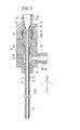
図7は、第2の実施形態に係る骨セメント注入用穿刺針10a(以下、「穿刺針10a」という)の一部省略断面図である。なお、第2の実施形態に係る穿刺針10aにおいて、上記第1の実施形態に係る穿刺針10と同一又は同様な機能及び効果を奏する要素には同一の参照符号を付し、詳細な説明を省略する。
[Second Embodiment]
FIG. 7 is a partially omitted cross-sectional view of a bone cement
第2の実施形態に係る穿刺針10aは、第1の実施形態に係る穿刺針10の外針12を、これとは別構成の外針12aに置き換えたものである。外針12aは、外針12のフレア形状部28及び第2の側孔24と同一構成のフレア形状部28a及び側孔(基端側孔部)24aを有するが、外針12よりも短く形成され、外針12の第1の側孔22に相当するものは設けられていない。
The
外針12aの先端は、骨に穿刺しやすいように、鋭利な刃先として構成されている。外針12aの構成材料としては、外針12の構成材料として例示したものと同様のものが挙げられる。外針12aの外径d3は、外針12の外径d2と同程度でよい。
The distal end of the
外針12aの最先端部から側孔の最も先端側の部位までの距離L4は、外針12aを骨に穿刺したとき、側孔24aが体外に確実に位置するように設定される。具体的には、距離L4は、100mm以上であり、好ましくは110mm以上に設定される。内針ハブ18を外針ハブ14に接続した状態において、外針12aの先端からの内針16の突出長さ、すなわち、内針16の先端と外針12aの先端との距離L5は、2〜15mmに設定されるのがよい。
The distance L4 from the most distal end portion of the
内針16の外径は、外針12aの内径d3と略同一に設定されるのがよく、具体的には、内針16を外針12aの中空部20にスムーズに挿入でき、且つ内針16の外周と外針12aの内周との間にほとんど隙間が生じない程度に設定されるのがよい。
The outer diameter of the
図8は、内管17を外針12aに挿入した状態を示す一部省略断面図である。図8に示すように、外針12aに内管17が挿通された状態で、外針12の最先端部で開口する減圧通路75が外針12aと内管17との間に形成される。この減圧通路75は、外針12aの先端開口と側孔24aとを連通する。
FIG. 8 is a partially omitted cross-sectional view showing a state in which the
内針ハブ18を外針ハブ14に装着した状態において、内管17は外針12aの先端部から突出することが好ましく、外針12aの先端からの内管17の突出長さ、すなわち、外針12aの先端と内管17の先端との距離L6は、1〜15mmに設定されるのがよい。
In a state where the
図9A〜図9D、図10A〜図10Cは、穿刺針10aを用いて骨セメントを骨内に注入する方法を説明する図である。穿刺針10aを用いて骨セメントを骨内に注入するには、まず、画像誘導下において穿刺位置及び穿刺目標を決定した後、外針12a及び外針ハブ14を内針16及び内針ハブ18に装着した組立体をハンマーで打撃して、外針12a及び内針16を穿刺目標の骨に穿刺する(図9A参照)。このとき、外針12aの先端開口が骨64内に位置するまで穿刺する。また、外針12a及び内針16を骨64に穿刺した状態で、側孔24aは体外に位置している。
9A to 9D and FIGS. 10A to 10C are diagrams illustrating a method of injecting bone cement into bone using the
上述したように、外針12aに内管17が挿通された状態で、内管17の先端部は、外針12aの先端部から突出するので、画像誘導下で外針12a及び内針16を骨に穿刺する際、内管17の先端部と、外針12aの先端部との段差がマーカーとなる。すなわち、当該段差が画像上で視覚的に認識しやすいため、外針12aの骨内への穿刺を簡単且つ確実に行うことできる。また、段差(マーカー)をX線で確認することで、減圧通路75の先端が骨内に刺入されたことを判断できる。
As described above, since the distal end portion of the
外針12a及び内針16を骨64に穿刺したら、外針12aを骨に穿刺したまま、内針16を外針12aから抜去する(図9B参照)。次に、外針12aに内管17を挿通するとともに、外針ハブ14のメイン接続口32に内管ハブ19を接続する(図9C参照)。これにより、外針12aと内管17との間に減圧通路75が形成され、外針12aを骨64に穿刺した状態で骨64内と側孔24aとが連通状態となる。
When the
次に、内部に骨セメント74を充填した注入デバイスとしてのシリンジ66を注入ポート56に接続する(図9D参照)。次に、シリンジ66内の骨セメント74を、内管ハブ19の中空部60及び骨セメント通路46を介して骨64内に注入する(図10A参照)。このとき、骨セメント74を注入した分、骨64内の気体又は液体は、外針12aの先端開口から減圧通路75内に流入し、減圧通路75を流れて側孔24aを介して外部に流出する。これにより、骨セメント74の注入による骨64内の内圧の上昇が防止され、この結果、骨セメント74が骨64外に漏出することを防止することができる。
Next, a
なお、骨セメント74を骨64内に注入する際に、サブ接続口38に吸引デバイス(たとえば、シリンジ等)を接続し、骨64内の気体又は液体の排出を補助するようにしてもよい。あるいは、骨64に穿刺した外針12aに内管17を挿入した状態で、サブ接続口38に吸引デバイスを接続し、骨セメント74を骨64内に注入する前に、吸引デバイスにより骨64内の気体又は液体を吸引しておくことで、骨64内を陰圧としておき、その後に骨セメント74を骨64内に注入してもよい。これにより、骨セメント74の注入による骨64内の内圧の上昇を防止することができる。
When injecting the
骨64内へ骨セメント74を所定量注入したら、外針12aを骨64に穿刺したまま、外針12aから内管17を抜去する(図10B参照)。このとき、骨セメント74は、内管17の抜去とともに外針12aの内部から除去されるため、外針12a内には付着していない。
When a predetermined amount of
次に、外針12aに内針16を再挿入するとともに、内針ハブ18を外針ハブ14に接続する。このとき、上述したように、外針12a内には骨セメント74が残存していない。このため、外針12aへの内針16の再挿入を確実に行うことが可能である。また、内針16の再挿入の際に骨セメント74が骨64内に押し込まれることがなく、骨64内に必要以上に骨セメント74が注入されることが防止されることから、骨64内へ骨セメント74を正確な注入量で注入することが可能となる。内針16を外針12aに再挿入したら、外針12a及び内針16を骨64から抜去する(図10C参照)。
Next, the
以上のように、穿刺針10aによれば、外針12aに内針16を挿入した状態で外針12a及び内針16の先端部を目的の骨に穿刺した後、外針12aから内針16を抜去し、次に外針12aに内管17を挿入すると、外針12aと内管17とにより2重管構造が構成される。そして、外針12aには側孔が設けられ、外針12aに内管17が挿通され且つ外針12aが骨に穿刺された状態では、減圧通路75及び側孔24aを介して、骨内と体外の空間とが連通する。これにより、骨セメントを骨内に注入したとき、骨内の気体又は液体(例えば、浸出液や血液など)が減圧通路75を流れて、体外に出ることが可能であるため、骨セメントの注入による骨内の内圧の上昇を防止することができる。従って、骨セメントが骨外に漏出することを防止することができる。
As described above, according to the
なお、第2の実施形態において、第1の実施形態と共通する各構成部分については、第1の実施形態における当該共通の各構成部分がもたらす作用及び効果と同一又は同様の作用及び効果が得られることは勿論である。 In the second embodiment, the same components and the same effects as those provided by the respective components in the first embodiment are the same as or similar to those in the first embodiment. Of course.
上述した第1及び第2の実施形態では、外針ハブ14の側面(Y方向を向く面)にサブ接続口38を設けた場合を説明したが、図11に示す変形例に係る外針ハブ14aのように、左右方向の一方の端部(X方向の端部)にサブ接続口39を設ける構成としてもよい。サブ接続口39は、サブ接続口38と同様の機能を有し、吸引デバイス等の他のデバイスや構造と接続可能である。
In the first and second embodiments described above, the case where the
経皮的椎体形成術では、複数の骨セメント注入用穿刺針を用いる場合に、互いの外針ハブが平行となる向きに、複数の骨セメント注入用穿刺針を患者の体に穿刺することがある。図11に示す外針ハブ14aのように、長手方向端部にサブ接続口39が設けられると、隣接する穿刺針同士でサブ接続口39が邪魔にならず、手技を円滑に行うことが可能となる。
In percutaneous vertebroplasty, when using multiple bone cement injection puncture needles, puncture the patient's body with multiple bone cement injection puncture needles so that the outer needle hubs are parallel to each other. There is. When the
[第3の実施形態]
図12は、第3の実施形態に係る骨セメント注入用穿刺針10b(以下、「穿刺針10b」という)の一部省略断面図である。なお、第3の実施形態に係る穿刺針10bにおいて、上記第1の実施形態に係る穿刺針10と同一又は同様な機能及び効果を奏する要素には同一の参照符号を付し、詳細な説明を省略する。
[Third Embodiment]
FIG. 12 is a partially omitted cross-sectional view of a bone cement
上述したように、第1及び第2の実施形態では、穿刺針10、10aの使用者が把持するためのグリップ15が外針ハブ14に設けられている(図1参照)。これに対し、第3の実施形態では、内針16の軸線方向に直角な方向に延在するグリップ76が内針ハブ18aに設けられ、外針ハブ14bには、外針ハブ14のグリップ15に相当するものは設けられていない。
As described above, in the first and second embodiments, the
外針ハブ14bは、グリップが設けられていない点以外は、外針ハブ14と同様の構成であり、第1通路36、第2通路42及びサブ接続口38を有している。内針ハブ18aは、グリップ76が設けられている点以外は、内針ハブ18と同様の構成である。穿刺針10bにおいて、外針12を第2の実施形態に係る穿刺針10aの外針12aに置き換えてもよい。
The
第3の実施形態に係る穿刺針10bによれば、第1及び第2の実施形態に係る穿刺針10、10aと同様に、内管17内の骨セメント通路46を介して骨セメントを骨内に注入し、その後に、外針12から内管17を抜去することで、外針12内に骨セメントが付着しない。このような利点を活かし、第3の実施形態に係る穿刺針10bでは、外針ハブ14bではなく、内針ハブ18aにグリップ76を設けている。すなわち、外針12内に骨セメントが付着しないことで外針12に内管17を確実に再挿入できることから、内針16が固定された内針ハブ18aにグリップ76を設けている。これにより、骨セメントの注入時にはグリップ76が外針ハブ14から取り外されているため、互いに近接する複数箇所に穿刺を行う場合でも、骨セメントの注入時にグリップ76が邪魔にならず、手技を円滑に行うことが可能となる。
According to the
なお、第3の実施形態において、第1の実施形態と共通する各構成部分については、第1の実施形態における当該共通の各構成部分がもたらす作用及び効果と同一又は同様の作用及び効果が得られることは勿論である。 Note that in the third embodiment, the same components and the same effects as those provided by the respective common components in the first embodiment are obtained for the components that are common to the first embodiment. Of course.
上記において、本発明について好適な実施の形態を挙げて説明したが、本発明は前記実施の形態に限定されるものではなく、本発明の要旨を逸脱しない範囲において、種々の改変が可能なことは言うまでもない。 In the above description, the present invention has been described with reference to preferred embodiments. However, the present invention is not limited to the above-described embodiments, and various modifications can be made without departing from the scope of the present invention. Needless to say.
10、10a、10b…骨セメント注入用穿刺針
12、12a…外針 14、14a、14b…外針ハブ
16…内針 17…内管
18、18a…内針ハブ 19…内管ハブ
22…第1の側孔 24…第2の側孔
24a…側孔 32…メイン接続口
38…サブ接続口 56…注入ポート
48、75…減圧通路
DESCRIPTION OF
Claims (6)
前記外針の基端部に固定され、前記外針の基端開口と連通する第1ポートを有する外針ハブと、
先端に針先が設けられ、且つ前記外針及び前記第1ポートに挿通可能な内針と、
前記内針の基端部に固定され、前記外針ハブに着脱可能な内針ハブと、
前記外針及び前記第1ポートに挿通可能な内管と、
前記内管の基端部に固定され、前記外針ハブに着脱可能であり、前記内管の基端開口と連通する第2ポートを有する内管ハブと、を備え、
前記外針に前記内管が挿通され且つ前記外針が骨に穿刺された状態において、前記骨内と前記基端側孔部とを連通する流路が前記外針と前記内管との間に形成される、
ことを特徴とする骨セメント注入用穿刺針。 An outer needle having a hollow structure in which a proximal hole is provided on the side surface in the vicinity of the proximal end,
An outer needle hub fixed to a proximal end portion of the outer needle and having a first port communicating with a proximal end opening of the outer needle;
A needle tip is provided at the tip, and an inner needle that can be inserted into the outer needle and the first port;
An inner needle hub fixed to the proximal end of the inner needle and detachable from the outer needle hub;
An inner tube that can be inserted into the outer needle and the first port;
An inner tube hub fixed to a proximal end portion of the inner tube, detachably attached to the outer needle hub, and having a second port communicating with the proximal end opening of the inner tube;
In a state where the inner tube is inserted into the outer needle and the outer needle is pierced into the bone, a flow path that communicates the inside of the bone and the proximal end side hole is between the outer needle and the inner tube. Formed into,
A puncture needle for injecting bone cement.
前記外針は、先端部近傍の側面に先端側孔部を有し、
前記外針に前記内管が挿通された状態で前記先端側孔部と前記基端側孔部とを連通する減圧通路が前記外針と前記内管との間に形成される、
ことを特徴とする骨セメント注入用穿刺針。 The puncture needle for bone cement injection according to claim 1,
The outer needle has a tip side hole on the side surface near the tip,
A pressure reducing passage that connects the distal end side hole and the proximal end side hole in a state where the inner tube is inserted through the outer needle is formed between the outer needle and the inner tube.
A puncture needle for injecting bone cement.
前記内管ハブを前記外針ハブに装着した状態で、前記内管の最先端部は、前記外針の最先端部と同じ位置か又は前記外針から突出する、
ことを特徴とする骨セメント注入用穿刺針。 The puncture needle for bone cement injection according to claim 2,
With the inner tube hub attached to the outer needle hub, the most distal portion of the inner tube protrudes from the same position as the most distal portion of the outer needle or the outer needle.
A puncture needle for injecting bone cement.
前記外針に前記内管が挿通された状態で、前記外針の最先端部で開口する減圧通路が前記外針と前記内管との間に形成される、
ことを特徴とする骨セメント注入用穿刺針。 The puncture needle for bone cement injection according to claim 1,
In a state where the inner tube is inserted through the outer needle, a decompression passage that opens at the most distal end portion of the outer needle is formed between the outer needle and the inner tube.
A puncture needle for injecting bone cement.
前記外針に前記内管が挿通された状態で、前記内管の先端部は、前記外針の先端部から突出する、
ことを特徴とする骨セメント注入用穿刺針。 The bone cement injection puncture needle according to claim 4,
In a state where the inner tube is inserted through the outer needle, the distal end portion of the inner tube protrudes from the distal end portion of the outer needle.
A puncture needle for injecting bone cement.
前記基端側孔部は、前記外針ハブ内に位置するとともに、前記外針ハブに設けられた第3ポートと連通する、The base end side hole is located in the outer needle hub and communicates with a third port provided in the outer needle hub.
ことを特徴とする骨セメント注入用穿刺針。A puncture needle for injecting bone cement.
Priority Applications (8)
| Application Number | Priority Date | Filing Date | Title |
|---|---|---|---|
| JP2010052300A JP5649108B2 (en) | 2010-03-09 | 2010-03-09 | Puncture needle for bone cement injection |
| PCT/JP2011/055221 WO2011111653A1 (en) | 2010-03-09 | 2011-03-07 | Bone cement injection puncture needle |
| ES11753311.7T ES2594977T3 (en) | 2010-03-09 | 2011-03-07 | Bone cement injection puncture needle |
| US13/582,296 US20120330320A1 (en) | 2010-03-09 | 2011-03-07 | Bone cement injection puncture needle |
| KR1020127023473A KR101692096B1 (en) | 2010-03-09 | 2011-03-07 | Bone cement injection puncture needle |
| EP11753311.7A EP2545872B1 (en) | 2010-03-09 | 2011-03-07 | Bone cement injection puncture needle |
| EP15201674.7A EP3017779B1 (en) | 2010-03-09 | 2011-03-07 | Bone cement injection puncture needle |
| CN201180013097.4A CN102791209B (en) | 2010-03-09 | 2011-03-07 | bone cement injection needle |
Applications Claiming Priority (1)
| Application Number | Priority Date | Filing Date | Title |
|---|---|---|---|
| JP2010052300A JP5649108B2 (en) | 2010-03-09 | 2010-03-09 | Puncture needle for bone cement injection |
Publications (3)
| Publication Number | Publication Date |
|---|---|
| JP2011182996A JP2011182996A (en) | 2011-09-22 |
| JP2011182996A5 JP2011182996A5 (en) | 2013-04-25 |
| JP5649108B2 true JP5649108B2 (en) | 2015-01-07 |
Family
ID=44563455
Family Applications (1)
| Application Number | Title | Priority Date | Filing Date |
|---|---|---|---|
| JP2010052300A Expired - Fee Related JP5649108B2 (en) | 2010-03-09 | 2010-03-09 | Puncture needle for bone cement injection |
Country Status (7)
| Country | Link |
|---|---|
| US (1) | US20120330320A1 (en) |
| EP (2) | EP2545872B1 (en) |
| JP (1) | JP5649108B2 (en) |
| KR (1) | KR101692096B1 (en) |
| CN (1) | CN102791209B (en) |
| ES (1) | ES2594977T3 (en) |
| WO (1) | WO2011111653A1 (en) |
Families Citing this family (14)
| Publication number | Priority date | Publication date | Assignee | Title |
|---|---|---|---|---|
| JP5649108B2 (en) | 2010-03-09 | 2015-01-07 | テルモ株式会社 | Puncture needle for bone cement injection |
| WO2012170805A2 (en) * | 2011-06-09 | 2012-12-13 | Knee Creations, Llc | Instruments and devices for subchondral joint repair |
| US20130072941A1 (en) * | 2011-09-16 | 2013-03-21 | Francisca Tan-Malecki | Cement Injector and Cement Injector Connectors, and Bone Cement Injector Assembly |
| CN102871713A (en) * | 2012-10-24 | 2013-01-16 | 李建民 | Bone cement injection device for percutaneous vertebroplasty |
| US20140142584A1 (en) * | 2012-11-16 | 2014-05-22 | Spinal Generations, Llc | Multichannel cannula and methods for using same |
| US9833272B2 (en) * | 2012-11-16 | 2017-12-05 | Spinal Generations, Llc | Multichannel cannula and methods for using same |
| KR101548809B1 (en) | 2013-10-30 | 2015-08-31 | 삼성전기주식회사 | Nozzle for oil dispenser |
| WO2015123733A1 (en) * | 2014-02-21 | 2015-08-27 | The Sydney Children's Hopsitals Network (Randwick And Westmead) | An implantable device |
| US9615863B2 (en) | 2014-10-22 | 2017-04-11 | Spinal Generations, Llc | Multichannel cannula for kyphoplasty and method of use |
| CN106955149A (en) * | 2016-01-11 | 2017-07-18 | 薛绍刚 | Bone cement injector |
| US10231846B2 (en) | 2016-08-19 | 2019-03-19 | Stryker European Holdings I, Llc | Bone graft delivery loading assembly |
| JP2020509874A (en) * | 2017-03-15 | 2020-04-02 | スミス アンド ネフュー インコーポレイテッド | Graft preparation and delivery devices and methods |
| KR102108620B1 (en) | 2018-03-09 | 2020-05-08 | 강호상 | Needle set for vertebroplasty |
| CN109363762A (en) * | 2018-12-18 | 2019-02-22 | 艾科美医疗器械(深圳)有限公司 | A kind of negative pressure suction type bone cement device for casting and method for filling |
Family Cites Families (12)
| Publication number | Priority date | Publication date | Assignee | Title |
|---|---|---|---|---|
| US5800439A (en) * | 1997-05-16 | 1998-09-01 | Clyburn; Terry A. | Cement injection and intramedullary canal drying system |
| US6575919B1 (en) * | 1999-10-19 | 2003-06-10 | Kyphon Inc. | Hand-held instruments that access interior body regions |
| JP3877982B2 (en) | 2001-07-17 | 2007-02-07 | 株式会社八光 | Biomedical cement injection device with tissue collection function |
| US20040097880A1 (en) * | 2002-11-19 | 2004-05-20 | Angiodynamics, Inc. | Combination thrombolytic infusion catheter and dilator system |
| CA2658544C (en) * | 2005-09-07 | 2012-12-11 | The Royal Institution For The Advancement Of Learning/Mcgill University | Device for injecting high viscosity material |
| US20080119821A1 (en) * | 2006-11-17 | 2008-05-22 | Warsaw Orthopedic, Inc. | Multiport Cannula |
| US8696679B2 (en) * | 2006-12-08 | 2014-04-15 | Dfine, Inc. | Bone treatment systems and methods |
| WO2008114483A1 (en) * | 2007-03-16 | 2008-09-25 | Olympus Terumo Biomaterials Corp. | Unit for resetting bone fracture caused by pyramidal compression |
| JP2008259810A (en) * | 2007-03-16 | 2008-10-30 | Olympus Terumo Biomaterials Corp | Unit for resetting bone fracture caused by vertebral compression |
| KR100950989B1 (en) * | 2008-07-03 | 2010-04-02 | (주)태연메디칼 | An apparatus for percutaneous delivery of bone-filling material |
| US8070728B2 (en) * | 2009-05-05 | 2011-12-06 | Societe De Commercialisation Des Produits De La Recherche Appliquee Socpra Sciences Et Genie S.E.C | Cannula assembly with detachable inner and outer cannulas |
| JP5649108B2 (en) | 2010-03-09 | 2015-01-07 | テルモ株式会社 | Puncture needle for bone cement injection |
-
2010
- 2010-03-09 JP JP2010052300A patent/JP5649108B2/en not_active Expired - Fee Related
-
2011
- 2011-03-07 EP EP11753311.7A patent/EP2545872B1/en not_active Not-in-force
- 2011-03-07 WO PCT/JP2011/055221 patent/WO2011111653A1/en active Application Filing
- 2011-03-07 EP EP15201674.7A patent/EP3017779B1/en not_active Not-in-force
- 2011-03-07 ES ES11753311.7T patent/ES2594977T3/en active Active
- 2011-03-07 KR KR1020127023473A patent/KR101692096B1/en active IP Right Grant
- 2011-03-07 US US13/582,296 patent/US20120330320A1/en not_active Abandoned
- 2011-03-07 CN CN201180013097.4A patent/CN102791209B/en not_active Expired - Fee Related
Also Published As
| Publication number | Publication date |
|---|---|
| CN102791209A (en) | 2012-11-21 |
| KR101692096B1 (en) | 2017-01-17 |
| US20120330320A1 (en) | 2012-12-27 |
| EP3017779B1 (en) | 2017-05-31 |
| ES2594977T3 (en) | 2016-12-27 |
| KR20120129948A (en) | 2012-11-28 |
| JP2011182996A (en) | 2011-09-22 |
| EP2545872A4 (en) | 2014-10-29 |
| EP3017779A1 (en) | 2016-05-11 |
| EP2545872A1 (en) | 2013-01-16 |
| CN102791209B (en) | 2015-08-26 |
| EP2545872B1 (en) | 2016-08-10 |
| WO2011111653A1 (en) | 2011-09-15 |
Similar Documents
| Publication | Publication Date | Title |
|---|---|---|
| JP5649108B2 (en) | Puncture needle for bone cement injection | |
| WO2010044462A1 (en) | Bone cement injection needle | |
| KR102031325B1 (en) | Apparatus and methods for aspirating tissue | |
| US20040153005A1 (en) | Bone marrow aspiration device with curved tip | |
| US6238400B1 (en) | Method and apparatus for trephination and irrigation of the frontal sinus cavity | |
| EP2699181B1 (en) | Cannula and kit for evaluation and preparation of bone tissue | |
| US20080103458A1 (en) | Collection needle | |
| AU2002331760A1 (en) | Collection needle | |
| JP2004033777A (en) | Bone marrow suction device | |
| US5423764A (en) | Lavage apparatus | |
| PT1449555E (en) | Needle cannula | |
| JP2011182994A (en) | Puncture needle for bone cement injection | |
| JP2011182995A (en) | Puncture needle for bone cement injection | |
| CN209826799U (en) | Spiral shell rotary-cut type coaxial puncture biopsy needle | |
| WO2021117649A1 (en) | Biopsy needle and tissue collection device | |
| WO2014049790A1 (en) | Puncture needle for injecting bone cement and method for producing same | |
| US20110137266A1 (en) | Catheter | |
| WO2012043289A1 (en) | Puncture needle for injecting bone cement and production method therefor |
Legal Events
| Date | Code | Title | Description |
|---|---|---|---|
| A521 | Written amendment |
Free format text: JAPANESE INTERMEDIATE CODE: A523 Effective date: 20130306 |
|
| A621 | Written request for application examination |
Free format text: JAPANESE INTERMEDIATE CODE: A621 Effective date: 20130306 |
|
| A521 | Written amendment |
Free format text: JAPANESE INTERMEDIATE CODE: A821 Effective date: 20130306 |
|
| A131 | Notification of reasons for refusal |
Free format text: JAPANESE INTERMEDIATE CODE: A131 Effective date: 20140304 |
|
| A521 | Written amendment |
Free format text: JAPANESE INTERMEDIATE CODE: A523 Effective date: 20140501 |
|
| TRDD | Decision of grant or rejection written | ||
| A01 | Written decision to grant a patent or to grant a registration (utility model) |
Free format text: JAPANESE INTERMEDIATE CODE: A01 Effective date: 20141007 |
|
| A61 | First payment of annual fees (during grant procedure) |
Free format text: JAPANESE INTERMEDIATE CODE: A61 Effective date: 20141106 |
|
| R150 | Certificate of patent or registration of utility model |
Ref document number: 5649108 Country of ref document: JP Free format text: JAPANESE INTERMEDIATE CODE: R150 |
|
| R250 | Receipt of annual fees |
Free format text: JAPANESE INTERMEDIATE CODE: R250 |
|
| LAPS | Cancellation because of no payment of annual fees |