JP5645637B2 - Subject information acquisition apparatus and subject information acquisition method - Google Patents
Subject information acquisition apparatus and subject information acquisition method Download PDFInfo
- Publication number
- JP5645637B2 JP5645637B2 JP2010280347A JP2010280347A JP5645637B2 JP 5645637 B2 JP5645637 B2 JP 5645637B2 JP 2010280347 A JP2010280347 A JP 2010280347A JP 2010280347 A JP2010280347 A JP 2010280347A JP 5645637 B2 JP5645637 B2 JP 5645637B2
- Authority
- JP
- Japan
- Prior art keywords
- time
- light
- signal
- subject
- series
- Prior art date
- Legal status (The legal status is an assumption and is not a legal conclusion. Google has not performed a legal analysis and makes no representation as to the accuracy of the status listed.)
- Expired - Fee Related
Links
Images


Description
本発明は、被検体情報取得装置および被検体情報取得方法に関する。 The present invention relates to a subject information acquisition apparatus and a subject information acquisition method.
レーザーなどの光源から生体に光を照射し、入射した光に基づいて得られる生体内の情報を画像化する光イメージング装置の研究が医療分野で積極的に進められている。この光イメージング技術の一つとして、Photo Acoustic Tomography(PAT:光音響トモグラ
フィー)がある。
Research on an optical imaging apparatus that irradiates light to a living body from a light source such as a laser and images in-vivo information obtained based on incident light has been actively promoted in the medical field. One such optical imaging technique is Photo Acoustic Tomography (PAT).
光音響トモグラフィーでは、光源から発生したパルス光を生体に照射し、生体内で伝播・拡散したパルス光のエネルギーを吸収した生体組織から発生した音響波(典型的に超音波である)を検出する。すなわち、腫瘍などの被検部位とそれ以外の組織との光エネルギーの吸収率の差を利用し、被検部位が照射された光エネルギーを吸収して瞬間的に膨張する際に発生する弾性波を音響波検出器(探触子やトランスデューサーとも言われる)で受信する。この受信信号を解析処理することにより初期圧力分布あるいは光吸収エネルギー密度分布(吸収係数分布と光量分布の積)に比例した画像を得ることができる。 In photoacoustic tomography, a living body is irradiated with pulsed light generated from a light source, and acoustic waves (typically ultrasonic waves) generated from living tissue that absorbs the energy of pulsed light that has propagated and diffused in the living body are detected. . In other words, using the difference in absorption rate of light energy between the test site such as a tumor and other tissues, the elastic wave generated when the test site absorbs the irradiated light energy and expands instantaneously Is received by an acoustic wave detector (also called a probe or a transducer). By analyzing this received signal, an image proportional to the initial pressure distribution or the light absorption energy density distribution (product of the absorption coefficient distribution and the light quantity distribution) can be obtained.
また、これらの画像情報は、様々な波長の光で計測することにより、被検体内の特定物質、例えば血液中に含まれるヘモグロビン濃度や血液の酸素飽和度などの定量的計測にも利用できる。近年、この光音響トモグラフィーを用いて、小動物の血管像をイメージングする前臨床研究や、この原理を乳がんなどの診断に応用する臨床研究が積極的に進められている。 Further, these image information can be used for quantitative measurement of a specific substance in a subject, for example, hemoglobin concentration contained in blood and blood oxygen saturation, by measuring with light of various wavelengths. In recent years, preclinical research for imaging blood vessels of small animals using this photoacoustic tomography and clinical research for applying this principle to diagnosis of breast cancer and the like have been actively promoted.
光音響トモグラフィー技術を用いた装置では、画像化する領域に対して音響波の測定領域が不十分な場合がある。例えば、被検体の全周囲方向からではなく、ある特定の方向からしか音響波を受信できない場合である。このような場合、ストリーク(放射線)状のアーティファクトが画像上に出現することが知られている。 In an apparatus using the photoacoustic tomography technique, an acoustic wave measurement area may be insufficient for an area to be imaged. For example, this is a case where an acoustic wave can be received only from a specific direction, not from the entire circumference of the subject. In such a case, it is known that streak (radiation) artifacts appear on the image.
一方、特許文献1には、ボクセルあるいはピクセルごとに光量分布の画像データで除算し、吸収係数分布の画像データを求めるやり方が開示されている。 On the other hand, Patent Document 1 discloses a method of obtaining image data of an absorption coefficient distribution by dividing the image data of the light amount distribution for each voxel or pixel.
ここで、上記のような、音響波の測定領域が不十分な測定系のPAT装置で得られた光吸収エネルギー分布の画像データを、特許文献1のやり方で求めると、光量の弱い領域においてアーティファクトが強調された画像が出力される課題があった。
これは、画像では初期音圧像とアーティファクトの区別がつかないため、初期音圧像及びアーティファクトともに光量補正が行われるためである。
Here, when the image data of the light absorption energy distribution obtained by the PAT apparatus of the measurement system having an insufficient acoustic wave measurement area as described above is obtained by the method of Patent Document 1, artifacts are obtained in the area where the light amount is weak. There has been a problem that an image in which is emphasized is output.
This is because the initial sound pressure image and the artifact cannot be distinguished from each other in the image, and the light amount correction is performed for both the initial sound pressure image and the artifact.
このような課題を解決するために、特許文献2では、音響波探触子から取得されるアナログ受信信号に対して、バリアブルゲインアンプを用いて光量補正を行い、その後に画像再構成により吸収係数分の画像データを算出する方法が開示されている。 In order to solve such a problem, in Patent Document 2, light amount correction is performed on an analog reception signal acquired from an acoustic wave probe using a variable gain amplifier, and then an absorption coefficient is obtained by image reconstruction. A method for calculating image data for a minute is disclosed.
このようにアナログ受信信号に対して、被検体の光量分布に基づいたゲインで補正すれば、吸収係数分布像のコントラストに寄与する受信信号のみを光量補正できる。そのため、初期音圧分布の画像データ自体を光量分布の画像データで補正する従来方法に比べて、アーティファクトの少ない画像を得ることができる。 In this way, if the analog reception signal is corrected with a gain based on the light amount distribution of the subject, only the reception signal contributing to the contrast of the absorption coefficient distribution image can be corrected. Therefore, an image with fewer artifacts can be obtained as compared with the conventional method in which the image data itself of the initial sound pressure distribution is corrected with the image data of the light amount distribution.
しかしながら,特許文献2ではアナログ受信信号をアンプで被検体の光量分布に対応した増幅を行うため、音圧の時間分解信号に対して任意の増幅を行うことができるバリアブルゲインアンプをすべての受信素子に対して用意する必要がある。その結果、装置のコストが増加する課題があった。 However, in Patent Document 2, an analog reception signal is amplified by an amplifier in accordance with the light quantity distribution of the subject. Therefore, a variable gain amplifier capable of performing arbitrary amplification on a sound pressure time-resolved signal is provided for all reception elements. It is necessary to prepare for. As a result, there is a problem that the cost of the apparatus increases.
また、アナログ受信信号自体を増幅するため、光量補正していない受信信号を解析して、被検体の光量分布データを求めるようなアダプティブ処理を行う場合、つまり、光量分布データが測定前に求められない場合、受信信号の光量補正ができない課題があった。 In addition, in order to amplify the analog received signal itself, when the received signal that has not been corrected for light intensity is analyzed and adaptive processing is performed to obtain the light intensity distribution data of the subject, the light intensity distribution data is obtained before measurement. If not, there is a problem that the received signal cannot be corrected.
本発明は上記の課題に鑑みてなされたものであり、その目的は、光音響トモグラフィーにおいて、装置のコストを抑制しつつ、光量補正によるアーティファクトの増加を低減するための技術を提供することである。 The present invention has been made in view of the above problems, and an object thereof is to provide a technique for reducing an increase in artifacts due to light amount correction while suppressing the cost of the apparatus in photoacoustic tomography. .
本発明は以下の構成を採用する。すなわち、光源と、前記光源から光を照射された被検体より発生する音響波を検出し、時系列の信号に変換する受信素子を含む検出器と、光が照射されたときの光量分布を表わす情報を格納するメモリと、前記光量分布を表わす情報を用いて、前記時系列の信号を補正する信号処理部と、前記補正された時系列の信号を用いて被検体情報を形成する情報処理部と、を有し、前記信号処理部は、前記受信素子の中心から所定の角度範囲内の領域における前記光量分布を時間データに変換し、前記時間データを用いて前記時系列の信号の補正を行うことを特徴とする被検体情報取得装置である。
本発明はまた、以下の構成を採用する。すなわち、光源と、前記光源から光を照射された被検体より発生する音響波を検出し、時系列の信号に変換する受信素子を含む検出器と、光が照射されたときの光量分布を表わす情報を格納するメモリと、前記光量分布を表わす情報を用いて、前記時系列の信号を補正する信号処理部と、前記補正された時系列の信号を用いて被検体情報を形成する情報処理部と、を有し、前記信号処理部は、前記光量分布を前記受信素子の指向性に基づいて重みづけし、前記重みづけされた光量分布を時間データに変換し、前記時間データを用いて前記時系列の信号の補正を行うことを特徴とする被検体情報取得装置である。
The present invention employs the following configuration. That is, a light source, detects an acoustic wave generated from a subject irradiated with light from the light source, a detector comprising a receiving element for converting the signal of the time series, the light amount distribution when light is irradiated forming a memory, using the information representative of the pre-Symbol light amount distribution, a signal processing unit for correcting the signal of the time series, the subject information using the signal of the corrected time series for storing information representing to a information processing unit, wherein the signal processing unit, the light intensity distribution is converted into time data in the area in the center at a predetermined angle range of the receiving device, of the time series with the time data An object information acquiring apparatus that performs signal correction.
The present invention also employs the following configuration. That is, a light source, a detector including a receiving element that detects an acoustic wave generated from a subject irradiated with light from the light source and converts it into a time-series signal, and a light amount distribution when the light is irradiated A memory for storing information; a signal processing unit for correcting the time-series signal using information representing the light quantity distribution; and an information processing unit for forming subject information using the corrected time-series signal And the signal processing unit weights the light amount distribution based on directivity of the receiving element, converts the weighted light amount distribution into time data, and uses the time data to An object information acquiring apparatus that corrects time-series signals.
本発明はまた、以下の構成を採用する。すなわち、光を照射された被検体より発生する音響波を検出し、時系列の信号に変換する工程と、光が照射されたときの光量分布を表わす情報を用いて、前記時系列の信号を補正する工程と、前記補正された時系列の信号を用いて被検体情報を形成する工程と、を有し、前記時系列の信号を補正する工程は、前記受信素子の中心から所定の角度範囲内の領域における前記光量分布を時間データに変換する工程と、前記時間データを用いて前記時系列の信号の補正を行う工程と、を含むことを特徴とする被検体情報取得方法である。
本発明はまた、以下の構成を採用する。すなわち、光を照射された被検体より発生する音響波を検出し、時系列の信号に変換する工程と、光が照射されたときの光量分布を表わす情報を用いて、前記時系列の信号を補正する工程と、前記補正された時系列の信号を用いて被検体情報を形成する工程と、を有し、前記時系列の信号を補正する工程は、前記光量分布を前記受信素子の指向性に基づいて重みづけする工程と、前記重みづけされた光量分布を時間データに変換する工程と、前記時間データを用いて前記時系列の信号の補正を行う工程と、を含むことを特徴とする被検体情報取得方法である。
The present invention also employs the following configuration. That is, using a step of detecting an acoustic wave into a signal of the time series generated from the object irradiated with light, the information representing the light amount distribution when light is irradiated, the signal of the time series a step of correcting, using said signal corrected time series includes a step of forming the subject information, and as engineering for correcting the signal of the time series is given from the center of the receiving element An object information acquisition method comprising: converting the light amount distribution in a region within an angle range into time data; and correcting the time-series signal using the time data. is there.
The present invention also employs the following configuration. That is, using the information representing the light amount distribution when the light is irradiated, the step of detecting the acoustic wave generated from the object irradiated with light and converting it to the time-series signal, And correcting the time-series signal using the corrected time-series signal, and the step of correcting the time-series signal includes the directivity of the receiving element. Weighting based on the step, converting the weighted light amount distribution into time data, and correcting the time-series signal using the time data. This is an object information acquisition method .
本発明によれば、光音響トモグラフィーにおいて、装置のコストを抑制しつつ、光量補正によるアーティファクトの増加を低減することが可能になる。 According to the present invention, in photoacoustic tomography, it is possible to reduce an increase in artifacts due to light amount correction while suppressing the cost of the apparatus.
以下、図面を参照しつつ本発明をより詳細に説明する。なお、同一の構成要素には原則として同一の参照番号を付して、説明を省略する。 Hereinafter, the present invention will be described in more detail with reference to the drawings. In principle, the same components are denoted by the same reference numerals, and description thereof is omitted.
(被検体情報取得装置)
図1を参照しながら本実施形態にかかる被検体情報取得装置の構成を説明する。本実施形態の被検体情報取得装置は、被検体の内部の光学特性値に関する被検体情報を画像データとして取得する装置である。本発明において、音響波とは、典型的には超音波であり、音波、超音波、音響波、光音響波、光超音波と呼ばれる弾性波を含む。本発明の被検体情報取得装置とは、被検体に光(電磁波)を照射することにより被検体内で発生した音響波(典型的には超音波)を受信して、被検体情報を画像データとして取得する光音響効果を利用した装置を含む。取得される被検体情報とは、光照射によって生じた音響波の発生源分布や、被検体内の初期音圧分布、あるいは初期音圧分布から導かれる光エネルギー吸収密度分布や、吸収係数分布、組織を構成する物質の濃度情報分布を示す。物質の濃度情報分布とは、例えば、酸素飽和度分布や酸化・還元ヘモグロビン濃度分布などである。
(Subject information acquisition device)
The configuration of the subject information acquisition apparatus according to the present embodiment will be described with reference to FIG. The subject information acquisition apparatus of the present embodiment is an apparatus that acquires subject information related to optical characteristic values inside the subject as image data. In the present invention, the acoustic wave is typically an ultrasonic wave, and includes an elastic wave called a sound wave, an ultrasonic wave, an acoustic wave, a photoacoustic wave, and an optical ultrasonic wave. The subject information acquisition apparatus of the present invention receives acoustic waves (typically ultrasonic waves) generated in a subject by irradiating the subject with light (electromagnetic waves), and converts subject information into image data. Including a device utilizing the photoacoustic effect acquired as follows. The acquired object information includes the source distribution of acoustic waves generated by light irradiation, the initial sound pressure distribution in the object, or the optical energy absorption density distribution derived from the initial sound pressure distribution, the absorption coefficient distribution, It shows the concentration information distribution of the substances that make up the tissue. The substance concentration information distribution is, for example, an oxygen saturation distribution, an oxidized / reduced hemoglobin concentration distribution, or the like.
本実施形態の被検体情報取得装置は、基本的なハード構成として、光源11、音響波の検出器としての音響波探触子17、信号処理部19を有する。光源11から発せられたパルス光12は例えばレンズ、ミラー、光ファイバ、拡散板などの光学系13により所望の光分布形状に加工されながら導かれ、生体などの被検体15に照射される。被検体15の内部を伝播した光のエネルギーの一部が血管などの光吸収体(結果的に音源となる)14に吸収されると、その光吸収体14の熱膨張により音響波(典型的には超音波)16が発生する。これは「光音響波」と呼ばれることもある。音響波16は音響波探触子17により受信されてアナログの受信信号(電気信号)に変換される。そして、アナログ受信信号は、信号収集器18で増幅やデジタル変換された後、信号処理部19で被検体の画像データに変換される。また、その画像データは表示装置20上で画像として表示される。
The subject information acquisition apparatus according to the present embodiment includes a
(光源11)
被検体が生体の場合、光源11からは生体を構成する成分のうち特定の成分に吸収される特定の波長の光を照射する。光源は、本実施形態の被検体情報取得装置と一体として設けられていても良いし、光源を分離して別体として設けられていても良い。光源としては数ナノから数百ナノ秒オーダーのパルス光を発生可能なパルス光源が好ましい。具体的には、効率的に光音響波を発生させるため、10ナノ秒程度のパルス幅が使われる。光源としては大出力が得られるためレーザーが好ましいが、レーザーのかわりに発光ダイオードなどを用いることも可能である。レーザーとしては、固体レーザー、ガスレーザー、色素レーザー、半導体レーザーなど様々なレーザーを使用することができる。照射のタイミング、光強度などは不図示の光源制御部によって制御される。なお、この光源制御部は通常、光源と一体化されている。本発明において、使用する光源の波長は、被検体内部まで光が伝搬する波長を使うことが望ましい。具体的には、被検体が生体の場合、500nm以上1200nm以下である。
(Light source 11)
When the subject is a living body, the
(光学系13)
光源11から照射された光12は、光学系13により、所望の光分布形状に加工されながら被検体に導かれる。光12を、光ファイバなどの光導波路などを用いて伝搬させることも可能である。光学系13は、例えば、光を反射するミラーや、光を集光したり拡大したり形状を変化させるレンズ、光を拡散させる拡散板、光ファイバなどである。このような光学部品は、光源から発せられた光12が被検体15に所望の形状で照射されれば、どのようなものを用いてもかまわない。なお、光はレンズで集光させるより、ある程度の面積に広げる方が生体への安全性ならびに診断領域を広げられるという観点で好ましい。
(Optical system 13)
The light 12 emitted from the
(被検体15及び光吸収体14)
これらは本発明の被検体情報取得装置の一部を構成するものではないが、以下に説明する。本発明の被検体情報取得装置は、血管の造影、人や動物の悪性腫瘍や血管疾患などの
診断や化学治療の経過観察などを主な目的とする。よって、被検体15としては生体、具体的には人体や動物の乳房や指、手足などの診断の対象部位が想定される。動物では、ねずみなど小動物の場合は特定の部位だけではなく、小動物全体が対象となることもある。
(Subject 15 and light absorber 14)
These do not constitute a part of the subject information acquisition apparatus of the present invention, but will be described below. The subject information acquisition apparatus of the present invention is mainly intended for blood vessel imaging, diagnosis of human and animal malignant tumors and vascular diseases, and follow-up of chemical treatment. Therefore, the subject 15 is assumed to be a living body, specifically, a target site for diagnosis such as breasts, fingers, and limbs of a human body or an animal. In the case of animals, in the case of a small animal such as a mouse, not only a specific part but also the whole small animal may be a target.
被検体内部の光吸収体14は、被検体内で相対的に吸収係数が高いものを示す。光吸収体14には、使用する光の波長にもよるが、例えば、人体が測定対象であれば酸化あるいは還元ヘモグロビンやそれらを含む多く含む血管あるいは新生血管を多く含む悪性腫瘍が該当する。
The
(音響波探触子17)
音響波探触子17は、パルス光により被検体表面及び被検体内部などで発生する音響波を検出する検出器である。音響波探触子17は、音響波を検知し、アナログ受信信号(以下、単に「アナログ信号」ともいう)である電気信号に変換する。以後、単に探触子あるいはトランスデューサということもある。圧電現象を用いたトランスデューサ、光の共振を用いたトランスデューサ、容量の変化を用いたトランスデューサなど音響波を検知できるものであれば、どのような音響波検出器を用いてもよい。本実施形態の音響波探触子17は、典型的には複数の受信素子が1次元あるいは2次元に配置されたものが良い。このような多次元配列素子を用いることで、同時に複数の場所で音響波を検出することができ、計測時間を短縮できる。その結果、被検体の振動などの影響を低減できる。
なお、本発明において音響波探触子17は、被検体15に対して、特定の方向のみの音響波を受信できるように設置されることを想定している。
(Acoustic wave probe 17)
The
In the present invention, it is assumed that the
(信号収集器18)
本実施形態の被検体情報取得装置は、探触子17より得られたアナログ受信信号を増幅し、デジタル受信信号(以下、単に「デジタル信号」ともいう)に変換する信号収集器18を有することが好ましい。信号収集器18は、典型的には増幅器、A/D変換器、FPGA(Field Programmable Gate Array)チップなどで構成される。探触子から得られる
受信信号が複数の場合は、同時に複数の信号を処理できることが望ましい。それにより、画像を形成するまでの時間を短縮できる。なお、本明細書において「受信信号」とは、探触子17から取得されるアナログ信号も、その後AD変換されたデジタル信号も含む概念である。そして、光吸収体からの光音響波に起因する受信信号は「光音響信号」ともいう。
(Signal collector 18)
The subject information acquisition apparatus of the present embodiment includes a
(信号処理部19)
信号処理部19は、主な役割として、信号収集器18から得られたデジタル受信信号を用いて、画像再構成を行い、被検体の内部の光学特性値情報を画像データとして取得する。また、本発明の特徴的処理として、信号処理部19は、信号収集器18から得られたデジタル受信信号に対して光量分布に応じた補正(以下、「光量補正」ともいう)を行う。その結果、測定領域が制限された場合に得られた初期圧力分布の画像あるいは光吸収エネルギー吸収分布の画像に対して、光量補正を行わない場合と比較して、相対的にアーティファクトの少ない画像を出力することができる。なお、ここで言う測定領域が制限された場合とは、被検体を取り囲むすべての方向からではなく、図1の被検体15と音響波探触子17の関係のように、ある特定の方向のみからしか音響波を受信できないことを示している。
(Signal processor 19)
As a main role, the
通常、信号処理部19には典型的にはワークステーションなどのコンピュータが用いられ、あらかじめプログラミングされたソフトウェアにより、受信信号処理や画像再構成処理などが行われる。そのため、バリアブルゲインアンプなどのハードウェア構成を追加する場合に比べて、信号処理部19で行われる処理は、低いコストで目的を達成できる。
Usually, a computer such as a workstation is typically used for the
ワークステーションで使われるソフトウェアは、例えば、受信信号に対してノイズ処理や光量補正などを行う信号処理モジュール19aと画像再構成を行う画像再構成モジュール19b、被検体の光量分布を算出する光量分布算出モジュール19dからなる。また、本発明の信号処理部19は、被検体の光量分布を保存するメモリ19cを有し、信号処理モジュールではこのメモリ19cに保存されたデータを参照しながら受信信号を補正する。ただし、信号処理モジュール19a、画像再構成モジュール19b、メモリ19c及び光量分布算出モジュール19dは、通常、ワークステーションなどのコンピュータ及び付属のソフトウェアとして扱われる。そのため、3つのモジュール及びメモリは、図1のように一つの信号処理装置19として扱われることが多い。
The software used in the workstation includes, for example, a
信号処理モジュール19aでは、基本機能として、信号収集器18から得られたデジタル受信信号に対して、被検体15の光量分布データに応じた光量補正を行う。なお、被検体15の光量分布データはメモリ19cに保存されているものを用いる。保存されている光量分布データは光量分布算出モジュール19dで計算されたもの、あるいは、予め他の場所で算出された光量分布データでも良い。ここで、光量分布データとは、光を照射された被検体内の各位置での光量を集積したデータを言う。
In the
光量分布算出モジュール19dでは、有限要素法やモンテ・カルロ法など生体などの被検体の光量分布を算出できる演算方法を用いて、被検体内の光量分布を算出する。メモリ19cは光量分布算出モジュール19dで算出された光量分布データや予め算出された光量分布データを格納する。光量分布算出モジュールは、本発明の演算部に相当する。
The light quantity
画像再構成モジュール19bでは、基本機能として、信号処理モジュール19aから得られる光量補正後の受信信号データを用いて、画像再構成による画像データの形成が行われる。画像再構成アルゴリズムとして、例えば、トモグラフィー技術で通常に用いられるタイムドメインあるいはフーリエドメインでの逆投影などが使われる。なお、再構成に多くの時間をかけることが可能な場合は、繰り返し処理を行う逐次再構成法(iterative method)などの画像再構成手法も利用することができる。PATの画像再構成手法には、代表的なものとして、フーリエ変換法、ユニバーサルバックプロジェクション法やフィルタードバックプロジェクション法、逐次再構成法などがあり、本発明においてはどのような画像再構成手法を用いても構わない。画像再構成モジュールは、本発明の画像処理部に相当する。
In the
(表示装置20)
表示装置20は信号処理部19で出力される画像データを表示する装置であり、典型的には液晶ディスプレイなどが利用される。なお、本発明の画像診断装置とは別に提供されていても良い。
(Display device 20)
The
(受信信号の処理)
次に、本発明の特徴的な処理である、信号処理部19で行うデジタル受信信号の光量補正処理と画像再構成処理の一例について、図2と図3も参照しつつ説明する。下記の番号は図2のフロー図における処理の番号と一致する。
(Received signal processing)
Next, an example of a digital received signal light amount correction process and an image reconstruction process performed by the
処理(1)(S200):被検体内の光量分布を算出する工程 Process (1) (S200): Step of calculating the light quantity distribution in the subject
光量分布算出モジュール19dにて、被検体の吸収係数分布、等価散乱係数分布、光照射強度分布や被検体形状に応じて、被検体内部の光量分布を算出する。
The light amount
被検体の吸収係数分布、等価散乱係数分布は、生体模擬ファントムなど予め物性値が既知の場合、その値を利用する。一方、吸収係数分布、等価散乱係数分布の値が未知の場合
、既知の方法を用いて受信信号から推定することができる。その場合、信号収集器18から得られたデジタル受信信号を解析処理し、被検体の光学特性値である平均的な吸収係数や等価散乱係数を推定する。また、受信信号からの推定が困難な場合、文献などに記載されている統計データなどから値を推定することもできる。
光照射強度分布は、被検体に照射される領域での光強度の分布であり、装置構成及び被検体形状が決まれば予め求めることができる。
被検体形状はカメラなどの撮影データから求めることもできるし、圧迫板などを用いて、被検体の形状を特定の形状に整形することも可能である。
As the absorption coefficient distribution and the equivalent scattering coefficient distribution of the object, when physical property values are already known, such as a living body simulation phantom, the values are used. On the other hand, when the values of the absorption coefficient distribution and the equivalent scattering coefficient distribution are unknown, they can be estimated from the received signal using a known method. In this case, the digital reception signal obtained from the
The light irradiation intensity distribution is a light intensity distribution in a region irradiated on the subject, and can be obtained in advance if the apparatus configuration and the subject shape are determined.
The subject shape can be obtained from imaging data from a camera or the like, or the shape of the subject can be shaped into a specific shape using a compression plate or the like.
このようなデータ群が既知であれば、光輸送方程式あるいは光拡散方程式を解くことで、被検体の光量分布を計算により求めることができる。なお、光輸送方程式あるいは光拡散方程式はモンテ・カルロ法、差分法、有限要素法など数値計算分野ですでに知られている方法を用いることで、解くことが可能である。 If such a data group is known, the light quantity distribution of the subject can be obtained by calculation by solving the light transport equation or the light diffusion equation. The light transport equation or the light diffusion equation can be solved by using a method already known in the numerical calculation field such as the Monte Carlo method, the difference method, or the finite element method.
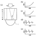
上述したように被検体の光量分布算出方法には様々な方法を考えることができるが、ここでは一例をあげて説明する。例えば、被検体の形状、平均的な吸収係数及び等価散乱係数、光照射強度は予め求められていると仮定する。次に、それらの情報を用いて、光拡散方程式を有限要素法により解いた光量分布データを求めると、図3(a)のような光量分布データが求められる。この例では、図1のように光12を音響波探触子17とは反対方向から入射した場合の例を示している。
As described above, various methods can be considered for the light amount distribution calculation method of the subject. Here, an example will be described. For example, it is assumed that the shape of the subject, the average absorption coefficient, the equivalent scattering coefficient, and the light irradiation intensity are obtained in advance. Next, when the light quantity distribution data obtained by solving the light diffusion equation by the finite element method is obtained using the information, the light quantity distribution data as shown in FIG. 3A is obtained. In this example, an example in which the light 12 is incident from the opposite direction to the
図3(a)においては、光照射近傍の光量が大きく、そこから離れるに従って、光が減衰し光量が小さくなっている。上記のような光量分布算出処理は、演算に必要な設定値である被検体の吸収係数分布、等価散乱係数分布、光照射強度分布、被検体形状が決まっていれば予め算出することができる。したがって、演算時間を低減するためにあらかじめ計算しておくこともできる。この場合、図1の信号処理器19に示したように、光量分布算出モジュール19dを装置に組み込む必要はない。ただし、被検体の吸収係数分布や散乱係数分布などが受信信号から推定される場合などは、信号収集器18で信号が受信された後に算出する必要がある。その場合、図1に示したように、光量分布算出モジュール19dを必要とする。
In FIG. 3A, the amount of light in the vicinity of the light irradiation is large, and the light attenuates and the amount of light decreases as the distance from the light irradiation increases. The light amount distribution calculation process as described above can be calculated in advance if the absorption coefficient distribution, equivalent scattering coefficient distribution, light irradiation intensity distribution, and object shape, which are set values necessary for the calculation, are determined. Therefore, it can be calculated in advance to reduce the calculation time. In this case, as shown in the
処理(2)(S201):処理(1)で算出された光量分布データをメモリに保存する工程 Process (2) (S201): Step of saving the light amount distribution data calculated in process (1) in the memory
信号処理器19がワークステーションなどのコンピュータである場合、上記の処理で算出された光量分布データをハードディスク内のファイルに保存し、使用するときにそのデータをワークステーション内のメモリ19cに格納する。あるいは、算出と同時に、その結果をメモリ19cに格納する。このように光量分布データをメモリ19cに格納できれば、どのような方法を用いても構わない。
When the
処理(3)(S202):メモリに保存された光量分布データを用いて、受信信号に対して光量分布(光量の大きさ)に応じた補正を行う工程 Process (3) (S202): A step of correcting the received signal according to the light amount distribution (the amount of light amount) using the light amount distribution data stored in the memory.
メモリに保存された光量分布データから音響波探触子17の受信素子に対応する、前記受信素子の受信面に垂直な方向の光量分布プロファイルを算出する。次に、被検体の平均的な音速に応じて、前述の光量分布プロファイルの距離データを時間データに変換する。その時間データに変換された光量分布プロファイルを受信信号データに対して徐算することで、光量分布の影響を補正する。
A light amount distribution profile in a direction perpendicular to the receiving surface of the receiving element corresponding to the receiving element of the
光量分布プロファイルは例えば、対応する受信素子の指向性の範囲の中心に作成しても
良い。この場合、受信素子を2次元配列した音響波検出器であれば、受信面に垂直な方向に光量分布プロファイルが作成される。
For example, the light amount distribution profile may be created at the center of the directivity range of the corresponding receiving element. In this case, in the case of an acoustic wave detector in which receiving elements are two-dimensionally arranged, a light amount distribution profile is created in a direction perpendicular to the receiving surface.
上記の処理を、図3を参照しつつ詳しく説明する。図3(b)は、図3(a)の点線aの領域の光量分布プロファイルを、横軸を距離(超音波探触子17の受信素子からの距離)、縦軸を光量としてプロットしたものである。なお、点線aは、音響波探触子17に含まれる一つの受信素子の受信面に対して垂直な方向である。ここでは、被検体を介して受信素子と反対側から光が照射されるため、受信素子から距離が離れるに従って、光量が増加している。受信素子側に近い位置は、照射された光が減衰しているため光量が小さい。
The above processing will be described in detail with reference to FIG. FIG. 3B is a plot of the light quantity distribution profile in the region indicated by the dotted line a in FIG. 3A with the horizontal axis representing distance (distance from the receiving element of the ultrasonic probe 17) and the vertical axis representing light quantity. It is. The dotted line a is a direction perpendicular to the receiving surface of one receiving element included in the
この図3(b)のデータを被検体の平均音速を用いて、横軸を時間に変更する。つまり、距離を音速で割ればよい。そこで得られたデータが図3(c)である。図3(c)は図3(b)のX軸が距離から時間(光照射から受信素子で受信されるまでの時間)に変更されただけで、グラフの形状などは変化しない。
すなわち、光量分布プロファイルは、ある受信素子から被検体に垂直な方向に線を引いた時に、その線上における光量を、被検体の深さを表わす値(距離や時間)と対応付けて示すデータである。したがって光量分布プロファイルは光量分布データから作成可能である。
In the data of FIG. 3B, the horizontal axis is changed to time by using the average sound speed of the subject. That is, the distance may be divided by the speed of sound. The data obtained there is shown in FIG. In FIG. 3C, the X-axis in FIG. 3B is merely changed from distance to time (time from light irradiation to reception by the receiving element), and the shape of the graph does not change.
In other words, the light amount distribution profile is data indicating the amount of light on a line associated with a value (distance or time) representing the depth of the subject when a line is drawn from a certain receiving element in a direction perpendicular to the subject. is there. Therefore, the light quantity distribution profile can be created from the light quantity distribution data.
なお、上記では各受信信号を補正する光量プロファイルを受信素子の受信面に対して垂直な領域とする例を示したが、光量プロファイル作成方法はこれに限られない。図3(a)の点線bは、一つの受信素子の中心とした、所定の角度θの範囲を示している。このとき、受信素子ごとに算出する光量プロファイルとして、この受信素子の中心から角度θの範囲にあり、かつ、受信素子の中心から等距離にある光量値を指向性で重み付けして積分した光量プロファイルを用いても良い。なお、この場合、角度範囲は受信素子が音響波を受信できる角度範囲であり、通常は、指向性から決定される。 In the above description, an example in which the light amount profile for correcting each received signal is an area perpendicular to the receiving surface of the receiving element is shown, but the light amount profile creation method is not limited to this. A dotted line b in FIG. 3A indicates a range of a predetermined angle θ that is the center of one receiving element. At this time, as the light intensity profile calculated for each receiving element, the light intensity profile obtained by integrating the light intensity values that are in the range of the angle θ from the center of the receiving element and equidistant from the center of the receiving element with the directivity. May be used. In this case, the angle range is an angle range in which the receiving element can receive an acoustic wave, and is usually determined from directivity.
図3(d)は音響波探触子の受信素子で得られたデジタル受信信号の一例である。図3(d)のグラフにおいて横軸は、右にいくほど、受信された時刻が早いことを意味する。通常、被検体15内部にある光吸収体14から発生する光音響波16は、図3(d)に示されているようなN型ライクな形状をしており、探触子に近い領域にある光吸収体から発生した光音響波ほど早く受信される。また、同じ形状、かつ、同じ吸収係数を持つ光吸収体から発生した光音響波ならば、受信素子に近いものほど、また、吸収する光量が大きいほど、大きな音圧で受信される。
FIG. 3D is an example of a digital reception signal obtained by the receiving element of the acoustic wave probe. In the graph of FIG. 3D, the horizontal axis means that the received time is earlier as it goes to the right. Usually, the photoacoustic wave 16 generated from the
通常、受信信号の音波の伝搬による音圧の減衰(回折効果)は、画像再構成において補正され、画像に反映される。一方、画像再構成においては光量の補正は行われないため、画像再構成後の画像は光量分布の影響を受けた画像となる。具体的に説明すると、図3(d)のような受信信号データを再構成した後に得られる画像は、通常、初期音圧分布p0(r)である。初期音圧分布p0(r)は、下記の式(1)のように吸収係数μa(r)と光量φ(r)の積に比例する。また、μa(r)とφ(r)の積は光吸収エネルギー密度H(r)と呼ばれる。

この式(1)から明らかなように、初期音圧分布p0(r)あるいは光吸収エネルギー密度H(r)の値は、光量φ(r)に影響される。従来の方法では、下の式(2)に示すように、再構成画像から吸収係数分布の画像データを求めるために、得られた画像データ
であるp0(r)あるいはH(r)をφ(r)で除算し、μa(r)を求め、光量の影響を排除する。この場合、H(r)あるいはp0(r)の画像データにアーティファクトが存在すると、それも光量で補正されるため、光量が小さい領域ではそこに存在するアーティファクトが強調される課題がある。
一方、本発明では、この被検体内の各位置(各部位)に照射される光量の大きさに応じてデジタル受信信号を補正することが特徴である。つまり、被検体内の光量の差を低減するように、デジタル受信信号を補正する。具体的には、図3(d)のデジタル受信信号に対して、図3(c)の時間データに変換した光量分布データを受信時間ごとに除算する。例えば、この補正処理で得られるデータが図3(e)である。この図から分かるように、光量の低い受信時間帯の信号が強調され、光量の影響が排除されている。このようにデジタル受信信号に対して光補正を行えば、光吸収体からの光音響波に起因する光音響信号のみに光補正を行うことが可能になる。 On the other hand, the present invention is characterized in that the digital reception signal is corrected in accordance with the amount of light emitted to each position (each part) in the subject. That is, the digital reception signal is corrected so as to reduce the difference in the amount of light in the subject. Specifically, the light amount distribution data converted into the time data of FIG. 3C is divided for each reception time with respect to the digital reception signal of FIG. For example, the data obtained by this correction process is shown in FIG. As can be seen from this figure, the signal in the reception time zone with a low light amount is emphasized, and the influence of the light amount is eliminated. By performing optical correction on the digital reception signal in this way, it is possible to perform optical correction only on the photoacoustic signal resulting from the photoacoustic wave from the light absorber.
式を用いて上記を説明する。ここでは議論を単純化するために、データを最初から離散的に扱う。まず、連続値である初期音圧分布p0(r)の画像を離散化して、行列として扱い、初期音圧分布の行列表現をP0とする。また、初期音圧分布の離散化データから発生する光音響波を各受信素子で検出される音響波データに変換する感度行列をYとする。なお、このYはヤコビ行列である。また、各受信素子で検出される音圧データの行列表現をDとすると、以下の式(3)が成り立つ。
D=Y・P0 …(3)
The above will be described using equations. Here, in order to simplify the discussion, the data is handled discretely from the beginning. First, the image of the initial sound pressure distribution p 0 (r), which is a continuous value, is discretized and treated as a matrix, and the matrix representation of the initial sound pressure distribution is P 0 . A sensitivity matrix for converting a photoacoustic wave generated from the discretized data of the initial sound pressure distribution into acoustic wave data detected by each receiving element is Y. Y is a Jacobian matrix. Further, when the matrix expression of the sound pressure data detected by each receiving element is D, the following expression (3) is established.
D = Y · P 0 (3)
また、P0は上記で述べたように吸収係数分布と光量分布の積で表現されるため、P0=Ma・Φと表現することができる。ここでΦは光量分布を表現する行列であり、Maは吸収係数分布を表現する行列である。つまり、式(3)は、以下の式(4)となる。
D=Y・Ma・Φ …(4)
両辺にΦの逆行列Φ−1をかければ、式(4)は、以下の式(5)となる。
D・Φ−1=Y・Ma …(5)
Further, since P 0 is expressed by the product of the absorption coefficient distribution and the light amount distribution as described above, it can be expressed as P 0 = Ma · Φ. Here, Φ is a matrix expressing the light quantity distribution, and Ma is a matrix expressing the absorption coefficient distribution. That is, Expression (3) becomes the following Expression (4).
D = Y · M a · Φ (4)
If an inverse matrix Φ −1 of Φ is applied to both sides, Expression (4) becomes the following Expression (5).
D · Φ −1 = Y · M a (5)
式(5)は、Φの逆行列を求め、それを各受信素子で検出される音圧データ行列Dにかけ、そのデータ(D・Φ−1)を用いて画像再構成することで、吸収係数分布の画像データMaを得ることができることを示している。このとき、式(2)のように画像データに光量分布補正をする必要はない。その結果、受信信号に光量分布補正を行うことができるため、画像再構成後に発生するアーティファクトを増加させることはなくなる。
なお、Φの逆行列は、例えば、受信素子の中心から等距離にある光量値を指向性で重み付けして積分したもの、近似的には、受信素子の受信面に対して垂直な方向の光量分布プロファイルなどで表現できる。また、ここではΦの逆行列として一例をあげて示したが、各受信信号が被検体内の光量分布の影響を低減するように補正されれば、デジタル受信信号に対してどのような補正手段を用いてもかまわない。つまり被検体内の光量の差が低減されるように各受信信号が補正されれば、どのような補正手段を用いてもよい。
Equation (5) calculates an inverse matrix of Φ, applies it to the sound pressure data matrix D detected by each receiving element, and reconstructs an image using the data (D · Φ −1 ), thereby obtaining an absorption coefficient. It shows that image data Ma of distribution can be obtained. At this time, it is not necessary to correct the light amount distribution on the image data as in equation (2). As a result, the light quantity distribution correction can be performed on the received signal, so that artifacts generated after image reconstruction are not increased.
Note that the inverse matrix of Φ is, for example, a light amount value equidistant from the center of the receiving element, integrated by weighting with directivity, and approximately, the light amount in a direction perpendicular to the receiving surface of the receiving element. It can be expressed by a distribution profile. In addition, although an example is given here as an inverse matrix of Φ, any correction means can be applied to the digital received signal if each received signal is corrected so as to reduce the influence of the light amount distribution in the subject. May be used. That is, any correction means may be used as long as each received signal is corrected so as to reduce the difference in the amount of light in the subject.
処理(4)(S203):光量補正されたデジタル受信信号を用いて画像再構成処理を行い、被検体の光学特性値分布に関連した画像データを形成する工程 Process (4) (S203): A step of performing image reconstruction processing using the digital received signal whose light amount has been corrected to form image data related to the optical characteristic value distribution of the subject.
図3(e)に示された光量補正されたデジタル受信信号を用いて画像再構成を行い、被検体15の吸収係数分布に関連した画像データを形成する。この処理に関しては、通常の
光音響トモグラフィーで用いられるどのような画像再構成処理を用いることが可能である。例えば、タイムドメインあるいはフーリエドメインでの逆投影などである。
Image reconstruction is performed using the digital reception signal with the light amount corrected shown in FIG. 3E to form image data related to the absorption coefficient distribution of the subject 15. For this process, any image reconstruction process used in normal photoacoustic tomography can be used. For example, back projection in the time domain or Fourier domain.
例えば、演算にタイムドメイン法の一つであるユニバーサルバックプロジェクション法を利用した場合、下記の式(6)に従って画像再構成を行う。
Ω0は任意の観測点Pに対する検出器dS0の立体角である。この投影データを式(6)の積
分に従って逆投影することで吸収係数分布μa(r)の画像データを得ることができる。
For example, when the universal back projection method, which is one of the time domain methods, is used for the calculation, image reconstruction is performed according to the following equation (6).
Ω 0 is the solid angle of the detector dS 0 with respect to an arbitrary observation point P. Image data of the absorption coefficient distribution μ a (r) can be obtained by back projecting the projection data according to the integration of Expression (6).
また、b(r0,t)は、以下の式(7)である。
なす角度である。これらの式で表したように、本発明では、通常の画像再構成とは異なり、光量分布補正された検出音波データを投影データとして用いることが特徴である。
B (r 0 , t) is the following equation (7).
図1の例では、画像形成において、音響波の受信範囲が制限され、アーティファクトが発生する。そのような場合であっても、以上の工程を行うことで、初期音圧分布画像あるいは光吸収エネルギー密度分布画像に対して、光量補正を行う従来技術よりも、コストアップすることなく、アーティファクトによる画像劣化が少ない画像を提供できる。 In the example of FIG. 1, in the image formation, the acoustic wave reception range is limited, and artifacts are generated. Even in such a case, by performing the above steps, the initial sound pressure distribution image or the light absorption energy density distribution image is not affected by the artifact without increasing the cost compared to the conventional technique for correcting the light amount. An image with little image deterioration can be provided.
<実施例1>
本実施形態を適用した光音響トモグラフィーを用いた被検体情報取得装置の一例について説明する。図1の装置概略図を用いて説明する。本実施例においては、光源11として波長1064nmで約10ナノ秒のパルス光を発生するQスイッチYAGレーザーを用いた。パルス光12から発せられる光パルスのエネルギーは0.6Jである。パルス光12をミラーとビームエキスパンダーなどの光学システム13を用いて、半径約2cm程度まで広げたあと、光を探触子17とは反対側の被検体に照射できるように光学系13をセッティングした。
<Example 1>
An example of an object information acquisition apparatus using photoacoustic tomography to which the present embodiment is applied will be described. This will be described with reference to the schematic diagram of FIG. In this example, a Q-switched YAG laser that generates pulsed light of about 10 nanoseconds at a wavelength of 1064 nm was used as the
被検体15としては生体を模擬した図4(a)のような長方形ファントムを用いた。フ
ァントムは、1%に希釈したイントラリピッドを寒天で固めたものを利用した。このファントムは光学的に均質であり、その平均的な吸収係数は約0.01mm−1、散乱係数は約0.7mm−1であった。また、このファントムのサイズは幅:5cm、高さ:5cm、奥行き:4cmとした。
ファントム内には図4(a)に示されているように、直径0.3mmの円柱状ゴムワイヤが光吸収体14として8個、図のように埋め込まれている。なお、それぞれの光吸収体14の吸収係数値はどれも同じである。また、ファントムや音響波探触子は音響マッチングのため、脱気された水で充たされた水槽の中に置かれている。
A rectangular phantom as shown in FIG. 4A simulating a living body was used as the subject 15. The phantom was obtained by solidifying intralipid diluted to 1% with agar. This phantom was optically homogeneous and had an average absorption coefficient of about 0.01 mm −1 and a scattering coefficient of about 0.7 mm −1 . Moreover, the size of this phantom was set to width: 5 cm, height: 5 cm, and depth: 4 cm.
As shown in FIG. 4A, eight cylindrical rubber wires having a diameter of 0.3 mm are embedded as
このようにセッティングされたファントムに対して、図1のように探触子17とは反対側のファントム表面にパルス光12を照射した。なお、音響波探触子17としてはPZT(ジルコン酸チタン酸鉛)で作られた超音波トランスデューサを用いた。このトランスデューサは2次元アレイ型で、素子数は345(15×23)の素子、素子ピッチは2mmである。また、素子の幅は約2mmである。
The phantom thus set was irradiated with the pulsed light 12 on the surface of the phantom opposite to the
図4(a)のように、パルス光12をファントム表面に照射すると、光が円柱状光吸収体14で吸収されることにより生じる光音響波が発生する。それらの光音響波を超音波トランスデューサ17で、345チャンネル同時に受信した。その受信信号をアンプ、ADコンバーター、FPGAからなる信号収集器18を用いて処理して、全チャンネルでの受信信号のデジタルデータを取得した。なお、信号のS/N比を向上させるために、32回レーザーを照射し、得られたすべての受信信号を平均化した。その後、得られたデジタルデータを信号処理器19であるワークステーション(WS)へ転送し、WS内に保存した。
As shown in FIG. 4A, when the
次に、WS内のソフトウェアプログラムである信号処理モジュールにて、ファントムの光学特性値、ファントム形状、光照射強度分布を用いて、ファントム内の光量分布データを有限要素法により求めた。さらに、この光量分布データから各受信素子の受信面に対して垂直方向の光量分布データを算出し、各受信データを光量で補正した。ここでは、時間データに直した光量プロファイルで受信データを除算する補正方法を用いた。 Next, the light quantity distribution data in the phantom was obtained by the finite element method using the optical characteristic value of the phantom, the phantom shape, and the light irradiation intensity distribution in the signal processing module which is a software program in the WS. Further, light quantity distribution data in the direction perpendicular to the receiving surface of each receiving element was calculated from the light quantity distribution data, and each received data was corrected with the light quantity. Here, a correction method is used in which received data is divided by a light amount profile corrected to time data.
さらに、この補正データを用いてWS内のソフトウェアプログラムである再構成モジュール19aにて、画像再構成を行った。ここでは複数の画像再構成手法の中でタイムドメイン方式であるユニバーサルバックプロジェクション法を用いて3次元のボリュームデータを形成した。このとき使用したボクセル間隔は0.025cmとした。画像化範囲は3.0cm×4.6cm×4.0cmである。そのときに得られた画像の一例を図4(b)に示す。なお、この図は3次元画像データにおいて、すべての吸収体が画像化できる方向の最大輝度を投影したMIP(Maximum Intensity Projection)像を示している。
Furthermore, image reconstruction was performed by the
次に、WS内に保存した光量補正していない受信信号を用いて、上記で採用された画像再構成手法を用いて、上記と同じ範囲である3.0cm×4.6cm×5.0cmの画像を算出した。さらに、従来技術と同様に、その画像を光量分布で補正した。ここでは再構成画像データの各ボクセル値を光量分布データのボクセル値で除算する方法を用いた。そのときに得られた画像の一例を図4(c)に示す。図4(c)も3次元画像データから、すべての吸収体が画像化できる方向の最大輝度を投影したMIP像である。 Next, using the received signal stored in the WS and not corrected for light quantity, the image reconstruction method employed above is used, and the same range as described above is 3.0 cm × 4.6 cm × 5.0 cm. Images were calculated. Further, the image was corrected with the light amount distribution as in the conventional technique. Here, a method of dividing each voxel value of the reconstructed image data by a voxel value of the light amount distribution data was used. An example of the image obtained at that time is shown in FIG. FIG. 4C is also an MIP image obtained by projecting the maximum luminance in the direction in which all absorbers can be imaged from the three-dimensional image data.
図4(b)と(c)を比較する。図4(c)では画像再構成後の光量補正のため、図中の点線で示した領域、つまり、光量の弱い領域のアーティファクトが目立っている。これは光量補正により、光量の少ない領域にあるすべての像が強調された結果である。一方、図4(b)においては、受信信号に対して光量補正を行ったため、アーティファクトは強調されない。つまり、受信信号のみが光量補正されているため、アーティファクトを強調
することはない。このように、音響波の計測領域が制限された場合において、デジタル受信信号を光量補正することで、従来法よりもアーティファクトの少ない画像が得られる。
FIG. 4B and FIG. 4C are compared. In FIG. 4C, for the light amount correction after the image reconstruction, artifacts in the region indicated by the dotted line in the drawing, that is, the region where the light amount is weak are conspicuous. This is a result of emphasizing all images in an area with a small amount of light by light amount correction. On the other hand, in FIG. 4B, since the light amount correction is performed on the received signal, the artifact is not emphasized. That is, since only the received signal is corrected for light quantity, the artifact is not emphasized. As described above, when the acoustic wave measurement region is limited, an image with fewer artifacts than the conventional method can be obtained by correcting the light amount of the digital reception signal.
<実施例2>
本実施形態を適用した光音響トモグラフィーを用いた被検体情報取得装置の一例について説明する。本実施例においては、実施例1と同様なファントム及び測定系を用いた。ただし、本実施例では受信信号の解析により、被検体の光学特性値を求める。
<Example 2>
An example of an object information acquisition apparatus using photoacoustic tomography to which the present embodiment is applied will be described. In this example, the same phantom and measurement system as in Example 1 were used. However, in this embodiment, the optical characteristic value of the subject is obtained by analyzing the received signal.
まず、図1と同じように探触子17とは反対方向から光を照射して光音響波を受信する。次に、図1には図示していないが探触子方向からも光を照射して光音響波を受信する。それぞれの受信信号に対して画像再構成を行い、2つの初期音圧分布画像を取得する。次に、それらの比をとり、その比のデータと計算により求めた光分布の比が最小になるように被検体の平均的な吸収係数と等価散乱係数を求めた。次に、求めた被検体の平均的な吸収係数と等価散乱係数、被検体形状、照射強度分布を用いて、光量分布算出モジュール19cで被検体の光量分布を求めた。次に、この光量分布データで実施例1と同様な方法で、受信信号を光量補正し、その補正された受信信号を用いて画像再構成を行い、画像を得た。
このような方法で得られた画像は図4(b)と同様なものであり、従来技術で得られた画像である図4(c)よりもアーティファクトが低減されていた。
First, as in FIG. 1, the photoacoustic wave is received by irradiating light from the opposite direction to the
The image obtained by such a method is the same as that shown in FIG. 4B, and the artifacts are reduced compared to FIG. 4C, which is an image obtained by the conventional technique.
以上のことから、アダプティブに受信信号を解析して被検体の光学定数を求め、その値を利用して受信信号を光補正しても、従来法よりもアーティファクトの少ない画像が得られる。 From the above, even if the received signal is adaptively analyzed to obtain the optical constant of the subject and the received signal is optically corrected using the value, an image with fewer artifacts than the conventional method can be obtained.
<実施例3>
本実施形態を適用した光音響トモグラフィーを用いた被検体情報取得装置の一例について説明する。本実施例においては、実施例1と同様なファントム及び測定系を用いた。
<Example 3>
An example of an object information acquisition apparatus using photoacoustic tomography to which the present embodiment is applied will be described. In this example, the same phantom and measurement system as in Example 1 were used.
まず、実施例1と同様にファントム内の光量分布を算出した。次に、各受信素子の中心から全角で30度以内、かつ、受信素子の中心から等距離にある光量分布の値を検出素子の指向性で重み付けしたものを積分した光量プロファイルを算出した。この光量プロファイルを用いて、実施例1と同様な方法で各受信信号データを補正し、補正した受信信号データを作成した。この補正した受信信号データを用いて、画像再構成を行い、相対的な吸収係数分布画像を算出した。
その結果、従来技術よりもアーティファクトが低減され、かつ、図4(b)よりも定量性の向上した吸収係数分布画像を得ることができた。
First, the light quantity distribution in the phantom was calculated in the same manner as in Example 1. Next, a light quantity profile was calculated by integrating the values of the light quantity distribution within 30 degrees in all angles from the center of each receiving element and equidistant from the center of the receiving element, weighted by the directivity of the detecting element. Using this light quantity profile, each received signal data was corrected in the same manner as in Example 1, and corrected received signal data was created. Using this corrected received signal data, image reconstruction was performed to calculate a relative absorption coefficient distribution image.
As a result, it was possible to obtain an absorption coefficient distribution image in which artifacts were reduced as compared with the prior art and quantitative characteristics were improved as compared with FIG.
以上のことから、探触子の指向性を考慮した光量プロファイルで受信信号を補正することで、定量性も保ちつつ、従来技術よりもアーティファクトが低減された光学特性値分布画像を得ることができる。 From the above, it is possible to obtain an optical characteristic value distribution image in which artifacts are reduced as compared with the prior art while maintaining quantitativeness by correcting the received signal with a light amount profile considering the directivity of the probe. .
11:光源,17:音響波探触子,19:信号処理部,19a:信号処理モジュール,19b:画像再構成モジュール,19c:メモリ,19d:光量分布算出モジュール 11: Light source, 17: Acoustic wave probe, 19: Signal processing unit, 19a: Signal processing module, 19b: Image reconstruction module, 19c: Memory, 19d: Light quantity distribution calculation module
Claims (18)
前記光源から光を照射された被検体より発生する音響波を検出し、時系列の信号に変換する受信素子を含む検出器と、
光が照射されたときの光量分布を表わす情報を格納するメモリと、
前記光量分布を表わす情報を用いて、前記時系列の信号を補正する信号処理部と、
前記補正された時系列の信号を用いて被検体情報を形成する情報処理部と、
を有し、
前記信号処理部は、前記受信素子の中心から所定の角度範囲内の領域における前記光量分布を時間データに変換し、前記時間データを用いて前記時系列の信号の補正を行う
ことを特徴とする被検体情報取得装置。 A light source;
A detector including a receiving element that detects an acoustic wave generated from a subject irradiated with light from the light source and converts the acoustic wave into a time-series signal ;
A memory for storing information representing the Kino light amount distribution and the light is irradiated,
Using the information representative of the pre-Symbol light amount distribution, a signal processing unit for correcting the signal of the time series,
An information processing unit which forms the subject information using the signal of the corrected time series,
Have
The signal processing unit converts the light amount distribution in a region within a predetermined angle range from the center of the receiving element into time data, and corrects the time-series signal using the time data. Subject information acquisition apparatus.
前記信号処理部は、前記時間データを用いて前記時系列のデジタル信号の補正を行うThe signal processing unit corrects the time-series digital signal using the time data.
ことを特徴とする請求項1に記載の被検体情報取得装置。The object information acquiring apparatus according to claim 1, wherein:
ことを特徴とする請求項1または2に記載の被検体情報取得装置。The subject information acquiring apparatus according to claim 1 or 2, wherein
ことを特徴とする請求項1から3のいずれか1項に記載の被検体情報取得装置。4. The subject information acquisition apparatus according to claim 1, wherein
ことを特徴とする請求項1から4のいずれか1項に記載の被検体情報取得装置。5. The subject information acquisition apparatus according to claim 1, wherein
前記光源から光を照射された被検体より発生する音響波を検出し、時系列の信号に変換する受信素子を含む検出器と、A detector including a receiving element that detects an acoustic wave generated from a subject irradiated with light from the light source and converts the acoustic wave into a time-series signal;
光が照射されたときの光量分布を表わす情報を格納するメモリと、A memory for storing information representing a light amount distribution when light is irradiated;
前記光量分布を表わす情報を用いて、前記時系列の信号を補正する信号処理部と、Using the information representing the light amount distribution, a signal processing unit for correcting the time-series signal;
前記補正された時系列の信号を用いて被検体情報を形成する情報処理部と、An information processing unit that forms subject information using the corrected time-series signal;
を有し、Have
前記信号処理部は、前記光量分布を前記受信素子の指向性に基づいて重みづけし、前記重みづけされた光量分布を時間データに変換し、前記時間データを用いて前記時系列の信号の補正を行うThe signal processing unit weights the light amount distribution based on directivity of the receiving element, converts the weighted light amount distribution into time data, and corrects the time-series signal using the time data. I do
ことを特徴とする被検体情報取得装置。A subject information acquisition apparatus characterized by the above.
前記信号処理部は、前記時間データを用いて前記時系列のデジタル信号の補正を行うThe signal processing unit corrects the time-series digital signal using the time data.
ことを特徴とする請求項6に記載の被検体情報取得装置。The object information acquiring apparatus according to claim 6.
ことを特徴とする請求項6または7に記載の被検体情報取得装置。The object information acquiring apparatus according to claim 6 or 7, characterized in that
ことを特徴とする請求項1から8のいずれか1項に記載の被検体情報取得装置。 The object information acquiring apparatus according to claim 1, wherein the object information acquiring apparatus is an object information acquiring apparatus.
ことを特徴とする請求項1から9のいずれか1項に記載の被検体情報取得装置。 The said signal processing part correct | amends the said time-sequential signal so that the difference in the light quantity irradiated to each position in the said subject may be reduced. The any one of Claim 1 to 9 characterized by the above-mentioned. The subject information acquisition apparatus described.
ことを特徴とする請求項1から10のいずれか1項に記載の被検体情報取得装置。 The signal processing unit, pre-Symbol object information acquiring apparatus according to any one of claims 1 to 10, characterized in that it comprises a calculator for calculating a light amount distribution.
ことを特徴とする請求項11に記載の被検体情報取得装置。 The arithmetic unit, the using object of the optical characteristic value and shape, the object information acquiring apparatus according to claim 11, characterized in that to calculate the light intensity distribution in the subject.
ことを特徴とする請求項12に記載の被検体情報取得装置。 The object information acquiring apparatus according to claim 12 , wherein the calculation unit obtains an optical characteristic value of the object by analyzing the time-series signal.
ことを特徴とする請求項1から13のいずれか1項に記載の被検体情報取得装置。 The signal processing unit on the basis of the previous SL light amount distribution, in a direction perpendicular from the reception surface before Ki受 signal elements, to create a light intensity distribution profile showing a relationship between the depth and light intensity of the subject, the light intensity distribution The subject information acquisition apparatus according to any one of claims 1 to 13 , wherein the time data is created using a profile and a sound velocity in the subject.
ことを特徴とする請求項1から14のいずれか1項に記載の被検体情報取得装置。The object information acquiring apparatus according to claim 1, wherein:
光が照射されたときの光量分布を表わす情報を用いて、前記時系列の信号を補正する工
程と、
前記補正された時系列の信号を用いて被検体情報を形成する工程と、
を有し、
前記時系列の信号を補正する工程は、
前記受信素子の中心から所定の角度範囲内の領域における前記光量分布を時間データに変換する工程と、
前記時間データを用いて前記時系列の信号の補正を行う工程と、を含む
ことを特徴とする被検体情報取得方法。 Detecting an acoustic wave generated from the subject irradiated with light and converting it into a time-series signal ;
Using the information that represents the light amount distribution when light is irradiated, the step of correcting the signal of the time series,
Forming the subject information using the signal of the corrected time series,
Have
As Engineering for correcting the signal of the time series,
Converting the light amount distribution in a region within a predetermined angle range from the center of the receiving element into time data;
And a step of correcting the time-series signal using the time data .
光が照射されたときの光量分布を表わす情報を用いて、前記時系列の信号を補正する工程と、Correcting the time-series signal using information representing a light amount distribution when light is irradiated; and
前記補正された時系列の信号を用いて被検体情報を形成する工程と、Forming subject information using the corrected time-series signal;
を有し、Have
前記時系列の信号を補正する工程は、The step of correcting the time-series signal includes:
前記光量分布を前記受信素子の指向性に基づいて重みづけする工程と、Weighting the light quantity distribution based on the directivity of the receiving element;
前記重みづけされた光量分布を時間データに変換する工程と、Converting the weighted light quantity distribution into time data;
前記時間データを用いて前記時系列の信号の補正を行う工程と、を含むCorrecting the time-series signal using the time data.
ことを特徴とする被検体情報取得方法。2. A method for acquiring subject information, characterized in that:
前記時系列の信号を補正する工程では、前記光量分布を表わす情報を用いて、前記時系列のデジタル信号を補正するIn the step of correcting the time series signal, the time series digital signal is corrected using information representing the light amount distribution.
ことを特徴とする請求項16または17に記載の被検体情報取得方法。The object information acquiring method according to claim 16 or 17, characterized in that:
Priority Applications (1)
| Application Number | Priority Date | Filing Date | Title |
|---|---|---|---|
| JP2010280347A JP5645637B2 (en) | 2010-12-16 | 2010-12-16 | Subject information acquisition apparatus and subject information acquisition method |
Applications Claiming Priority (1)
| Application Number | Priority Date | Filing Date | Title |
|---|---|---|---|
| JP2010280347A JP5645637B2 (en) | 2010-12-16 | 2010-12-16 | Subject information acquisition apparatus and subject information acquisition method |
Publications (3)
| Publication Number | Publication Date |
|---|---|
| JP2012125447A JP2012125447A (en) | 2012-07-05 |
| JP2012125447A5 JP2012125447A5 (en) | 2014-02-06 |
| JP5645637B2 true JP5645637B2 (en) | 2014-12-24 |
Family
ID=46643202
Family Applications (1)
| Application Number | Title | Priority Date | Filing Date |
|---|---|---|---|
| JP2010280347A Expired - Fee Related JP5645637B2 (en) | 2010-12-16 | 2010-12-16 | Subject information acquisition apparatus and subject information acquisition method |
Country Status (1)
| Country | Link |
|---|---|
| JP (1) | JP5645637B2 (en) |
Cited By (1)
| Publication number | Priority date | Publication date | Assignee | Title |
|---|---|---|---|---|
| RU2601262C2 (en) * | 2012-10-17 | 2016-10-27 | Родэ Унд Шварц Гмбх Унд Ко. Кг | Method and device for broadband high isolation coupling |
Families Citing this family (4)
| Publication number | Priority date | Publication date | Assignee | Title |
|---|---|---|---|---|
| JP6071285B2 (en) * | 2012-07-06 | 2017-02-01 | キヤノン株式会社 | Capacitive transducer |
| JP5984547B2 (en) | 2012-07-17 | 2016-09-06 | キヤノン株式会社 | Subject information acquisition apparatus and control method thereof |
| US10342436B2 (en) * | 2014-08-26 | 2019-07-09 | Canon Kabushiki Kaisha | Object information acquiring apparatus and processing method |
| JP6422330B2 (en) * | 2014-12-22 | 2018-11-14 | キヤノン株式会社 | Subject information acquisition apparatus, information processing apparatus, and processing method |
Family Cites Families (2)
| Publication number | Priority date | Publication date | Assignee | Title |
|---|---|---|---|---|
| JP4945273B2 (en) * | 2006-04-24 | 2012-06-06 | 株式会社東芝 | Ultrasonic diagnostic apparatus and control program for ultrasonic diagnostic apparatus |
| CN102131463B (en) * | 2008-08-27 | 2013-01-16 | 佳能株式会社 | Device for processing information relating to living body and method for processing information relating to living body |
-
2010
- 2010-12-16 JP JP2010280347A patent/JP5645637B2/en not_active Expired - Fee Related
Cited By (1)
| Publication number | Priority date | Publication date | Assignee | Title |
|---|---|---|---|---|
| RU2601262C2 (en) * | 2012-10-17 | 2016-10-27 | Родэ Унд Шварц Гмбх Унд Ко. Кг | Method and device for broadband high isolation coupling |
Also Published As
| Publication number | Publication date |
|---|---|
| JP2012125447A (en) | 2012-07-05 |
Similar Documents
| Publication | Publication Date | Title |
|---|---|---|
| JP5777358B2 (en) | Subject information acquisition apparatus and signal processing method | |
| JP5783779B2 (en) | Subject information acquisition apparatus and subject information acquisition method | |
| JP5661451B2 (en) | Subject information acquisition apparatus and subject information acquisition method | |
| JP5850633B2 (en) | Subject information acquisition device | |
| JP5528083B2 (en) | Image generating apparatus, image generating method, and program | |
| JP5496098B2 (en) | Subject information acquisition apparatus and control method thereof | |
| JP5586977B2 (en) | Subject information acquisition apparatus and subject information acquisition method | |
| JP6132466B2 (en) | Subject information acquisition apparatus and subject information acquisition method | |
| JP2010088627A (en) | Apparatus and method for processing biological information | |
| JP2010088627A5 (en) | ||
| JP5197217B2 (en) | Biological information imaging apparatus and image construction method | |
| JP6238539B2 (en) | Processing apparatus, subject information acquisition apparatus, and processing method | |
| JP5645637B2 (en) | Subject information acquisition apparatus and subject information acquisition method | |
| JP6222936B2 (en) | Apparatus and image generation method | |
| JP5885437B2 (en) | Photoacoustic apparatus and processing method | |
| JP6053339B2 (en) | Subject information acquisition apparatus and subject information acquisition method | |
| JP6300977B2 (en) | Subject information acquisition apparatus and subject information acquisition method | |
| JP2013188489A (en) | Subject information processing apparatus and method for operating the same | |
| JP2014147825A (en) | Image generation device, image generation method, and program | |
| JP6109359B2 (en) | Subject information acquisition apparatus and subject information acquisition method | |
| JP6513121B2 (en) | Processing apparatus, object information acquiring apparatus, display method of photoacoustic image, and program |
Legal Events
| Date | Code | Title | Description |
|---|---|---|---|
| A521 | Request for written amendment filed |
Free format text: JAPANESE INTERMEDIATE CODE: A523 Effective date: 20131213 |
|
| A621 | Written request for application examination |
Free format text: JAPANESE INTERMEDIATE CODE: A621 Effective date: 20131213 |
|
| A131 | Notification of reasons for refusal |
Free format text: JAPANESE INTERMEDIATE CODE: A131 Effective date: 20140715 |
|
| A977 | Report on retrieval |
Free format text: JAPANESE INTERMEDIATE CODE: A971007 Effective date: 20140718 |
|
| A521 | Request for written amendment filed |
Free format text: JAPANESE INTERMEDIATE CODE: A523 Effective date: 20140912 |
|
| TRDD | Decision of grant or rejection written | ||
| A01 | Written decision to grant a patent or to grant a registration (utility model) |
Free format text: JAPANESE INTERMEDIATE CODE: A01 Effective date: 20141007 |
|
| A61 | First payment of annual fees (during grant procedure) |
Free format text: JAPANESE INTERMEDIATE CODE: A61 Effective date: 20141104 |
|
| R151 | Written notification of patent or utility model registration |
Ref document number: 5645637 Country of ref document: JP Free format text: JAPANESE INTERMEDIATE CODE: R151 |
|
| LAPS | Cancellation because of no payment of annual fees |