JP5640149B2 - Guidewire and signal analyzer for pacing site optimization - Google Patents
Guidewire and signal analyzer for pacing site optimization Download PDFInfo
- Publication number
- JP5640149B2 JP5640149B2 JP2013527379A JP2013527379A JP5640149B2 JP 5640149 B2 JP5640149 B2 JP 5640149B2 JP 2013527379 A JP2013527379 A JP 2013527379A JP 2013527379 A JP2013527379 A JP 2013527379A JP 5640149 B2 JP5640149 B2 JP 5640149B2
- Authority
- JP
- Japan
- Prior art keywords
- guidewire
- site
- mapping
- signal
- pacing
- Prior art date
- Legal status (The legal status is an assumption and is not a legal conclusion. Google has not performed a legal analysis and makes no representation as to the accuracy of the status listed.)
- Expired - Fee Related
Links
Images


Classifications
-
- A—HUMAN NECESSITIES
- A61—MEDICAL OR VETERINARY SCIENCE; HYGIENE
- A61N—ELECTROTHERAPY; MAGNETOTHERAPY; RADIATION THERAPY; ULTRASOUND THERAPY
- A61N1/00—Electrotherapy; Circuits therefor
- A61N1/02—Details
- A61N1/04—Electrodes
- A61N1/05—Electrodes for implantation or insertion into the body, e.g. heart electrode
- A61N1/056—Transvascular endocardial electrode systems
-
- A—HUMAN NECESSITIES
- A61—MEDICAL OR VETERINARY SCIENCE; HYGIENE
- A61B—DIAGNOSIS; SURGERY; IDENTIFICATION
- A61B5/00—Measuring for diagnostic purposes; Identification of persons
- A61B5/24—Detecting, measuring or recording bioelectric or biomagnetic signals of the body or parts thereof
- A61B5/25—Bioelectric electrodes therefor
- A61B5/279—Bioelectric electrodes therefor specially adapted for particular uses
- A61B5/28—Bioelectric electrodes therefor specially adapted for particular uses for electrocardiography [ECG]
- A61B5/283—Invasive
- A61B5/287—Holders for multiple electrodes, e.g. electrode catheters for electrophysiological study [EPS]
-
- A—HUMAN NECESSITIES
- A61—MEDICAL OR VETERINARY SCIENCE; HYGIENE
- A61B—DIAGNOSIS; SURGERY; IDENTIFICATION
- A61B5/00—Measuring for diagnostic purposes; Identification of persons
- A61B5/24—Detecting, measuring or recording bioelectric or biomagnetic signals of the body or parts thereof
- A61B5/25—Bioelectric electrodes therefor
- A61B5/279—Bioelectric electrodes therefor specially adapted for particular uses
- A61B5/28—Bioelectric electrodes therefor specially adapted for particular uses for electrocardiography [ECG]
- A61B5/283—Invasive
- A61B5/29—Invasive for permanent or long-term implantation
-
- A—HUMAN NECESSITIES
- A61—MEDICAL OR VETERINARY SCIENCE; HYGIENE
- A61B—DIAGNOSIS; SURGERY; IDENTIFICATION
- A61B5/00—Measuring for diagnostic purposes; Identification of persons
- A61B5/24—Detecting, measuring or recording bioelectric or biomagnetic signals of the body or parts thereof
- A61B5/316—Modalities, i.e. specific diagnostic methods
- A61B5/318—Heart-related electrical modalities, e.g. electrocardiography [ECG]
- A61B5/346—Analysis of electrocardiograms
- A61B5/349—Detecting specific parameters of the electrocardiograph cycle
- A61B5/366—Detecting abnormal QRS complex, e.g. widening
-
- A—HUMAN NECESSITIES
- A61—MEDICAL OR VETERINARY SCIENCE; HYGIENE
- A61B—DIAGNOSIS; SURGERY; IDENTIFICATION
- A61B5/00—Measuring for diagnostic purposes; Identification of persons
- A61B5/68—Arrangements of detecting, measuring or recording means, e.g. sensors, in relation to patient
- A61B5/6846—Arrangements of detecting, measuring or recording means, e.g. sensors, in relation to patient specially adapted to be brought in contact with an internal body part, i.e. invasive
- A61B5/6847—Arrangements of detecting, measuring or recording means, e.g. sensors, in relation to patient specially adapted to be brought in contact with an internal body part, i.e. invasive mounted on an invasive device
- A61B5/6851—Guide wires
-
- A—HUMAN NECESSITIES
- A61—MEDICAL OR VETERINARY SCIENCE; HYGIENE
- A61N—ELECTROTHERAPY; MAGNETOTHERAPY; RADIATION THERAPY; ULTRASOUND THERAPY
- A61N1/00—Electrotherapy; Circuits therefor
- A61N1/18—Applying electric currents by contact electrodes
- A61N1/32—Applying electric currents by contact electrodes alternating or intermittent currents
- A61N1/36—Applying electric currents by contact electrodes alternating or intermittent currents for stimulation
- A61N1/372—Arrangements in connection with the implantation of stimulators
- A61N1/37211—Means for communicating with stimulators
- A61N1/37235—Aspects of the external programmer
- A61N1/37241—Aspects of the external programmer providing test stimulations
-
- A—HUMAN NECESSITIES
- A61—MEDICAL OR VETERINARY SCIENCE; HYGIENE
- A61N—ELECTROTHERAPY; MAGNETOTHERAPY; RADIATION THERAPY; ULTRASOUND THERAPY
- A61N1/00—Electrotherapy; Circuits therefor
- A61N1/02—Details
- A61N1/04—Electrodes
- A61N1/05—Electrodes for implantation or insertion into the body, e.g. heart electrode
- A61N1/056—Transvascular endocardial electrode systems
- A61N2001/0585—Coronary sinus electrodes
Description
本発明は、一般に、埋め込み型医療デバイスに関する。より具体的には、本発明は、心臓リード埋め込みシステム、デバイス、およびリード埋め込みのための方法に関する。 The present invention relates generally to implantable medical devices. More specifically, the present invention relates to cardiac lead implantation systems, devices, and methods for lead implantation.
心房および/または心室の収縮の律動および協調を改善することを期して、ペーシング刺激を1つまたは複数の心腔へ供給するために、心調律管理デバイスが使用される。心臓再同期療法(CRT)では、例えば、複数のリードが、典型的には、心臓内に、または心臓の近くに経静脈的に送り込まれ、これは、心臓電気活動のセンシング(感知)を行い、電気刺激療法を心臓に施すために心筋と接触する複数のリード電極を備える。いくつかの心臓ペースメーカは、複数の心腔のペーシングを行うことによってCRT療法を施すことができる。いくつかの技術では、例えば、ペーシング・パルスを複数の心腔に順に送り込み、これにより、心腔を同期して収縮させ、心臓のポンプ能力および効率を高める。左右心室の収縮の同期不全の場合、例えば、両心室ペーシング療法を使用して、心室の一方または両方をペーシングし、心拍出量を高めることが可能である。他の技術では、双心房ペーシングまたは4つすべての心腔のペーシングを実行して心拍出量を高めることができる。 A cardiac rhythm management device is used to deliver pacing stimuli to one or more heart chambers in an effort to improve the rhythm and coordination of atrial and / or ventricular contractions. In cardiac resynchronization therapy (CRT), for example, multiple leads are typically delivered intravenously into or near the heart, which provides cardiac electrical activity sensing. A plurality of lead electrodes in contact with the myocardium for applying electrical stimulation therapy to the heart. Some cardiac pacemakers can administer CRT therapy by pacing multiple heart chambers. Some techniques, for example, send pacing pulses sequentially into multiple heart chambers, thereby causing the heart chambers to contract in synchrony, increasing the pumping capacity and efficiency of the heart. In the case of dyssynchrony of left and right ventricle contraction, for example, biventricular pacing therapy can be used to pace one or both ventricles to increase cardiac output. Other techniques may perform bi-atrial pacing or pacing of all four heart chambers to increase cardiac output.
CRT用途におけるリード送り込みは、典型的には、心臓内、または心臓の近くの異なる標的ペーシング部位に複数のリードを送り込むことを伴う。いくつかの用途では、この方法は、リードを冠状静脈に通し、心静脈中枝(middle branch cardiac vein)または心静脈後枝(posterior branch cardiac vein)などの心臓の左側に隣接する位置に置かれた血管枝内に送り込む操作を伴いうる。典型的には、臨床医がリードを操作して心臓内、または心臓の近くの標的ペーシング部位に送り込み、部位の適所に到達した後、複数の電気的クリップをリードに接続して、ペーシング・システム・アナライザ(PSA)またはプログラミング・デバイスを使ってさまざまなセンシングおよびインピーダンス測定を実行することができるようにしなければならない。いくつかの場合において、リードの埋め込みは、患者の血流内に造影剤を注入し、次いで、その特定の患者について、蛍光透視鏡モニタを使用して選択する血管枝を決定することによって静脈造影図を使用して実行される。 Lead delivery in CRT applications typically involves delivering multiple leads to different target pacing sites in or near the heart. In some applications, the method passes the lead through the coronary vein and is placed adjacent to the left side of the heart, such as the middle branch cardiary vein or the post-cardiac vein cardi vein. It may be accompanied by an operation of feeding into the vascular branch. Typically, a clinician manipulates a lead to deliver it to a target pacing site in or near the heart, and after reaching the appropriate location in the site, connects multiple electrical clips to the lead to provide a pacing system It must be possible to perform various sensing and impedance measurements using an analyzer (PSA) or programming device. In some cases, lead implantation may be performed by injecting a contrast agent into the patient's bloodstream and then determining the vessel branch to select for that particular patient using a fluoroscopic monitor. Performed using the diagram.
CRT用途のためのリード留置は、試行錯誤を繰り返して行うことが多く、多くの場合に、臨床医がリードを操作し、何回かペーシング部位の有効性をテストしてから適切な場所を見つける。リード・ペーシング部位の選択は、CRT療法への血液動態反応に対し著しい影響を及ぼしうる。その結果、適切なペーシング部位を決定するために、いくつかのCRT埋め込みは、それぞれの埋め込まれたリード電極と体内に配置された別のリード電極もしくは表面EKG電極などの基準点との間でさまざまなタイミング間隔を測定することを伴う。左心室ペーシング療法を実施する両心室同期システムでは、例えば、左心室脱分極(例えば、Q−LVまたはQ1−LV)に関連する第1の特徴と第2の特徴との間のタイミング間隔が、結果として活動を引き起こすそれぞれの提案された左心室ペーシング部位について計算されうる。CRTに対する患者の反応性に関連するタイミング間隔に基づき、臨床医は、次いで、最新の活動の場所に基づき部位の選択を決定することができる。血管のサイズおよび標的部位にリードを埋め込む容易さなどの他の要因も、臨床医がリード埋め込みのための部位の選択を決定する際に考慮することができる。 Lead placement for CRT applications is often a trial-and-error process, and in many cases the clinician manipulates the lead and tests the effectiveness of the pacing site several times before finding the right place . The choice of lead pacing site can have a significant impact on the hemodynamic response to CRT therapy. As a result, in order to determine the appropriate pacing site, several CRT implants vary between each implanted lead electrode and a reference point such as another lead electrode or surface EKG electrode placed in the body. With measuring the exact timing interval. In a biventricular synchronization system that performs left ventricular pacing therapy, for example, the timing interval between a first feature and a second feature associated with left ventricular depolarization (eg, Q-LV or Q1-LV) is: As a result, each proposed left ventricular pacing site that causes activity can be calculated. Based on the timing interval associated with the patient's responsiveness to CRT, the clinician can then determine the site selection based on the location of the latest activity. Other factors such as vessel size and ease of implanting the lead at the target site may also be considered when the clinician determines the site selection for lead implantation.
本発明は、心臓リード埋め込みシステム、デバイス、およびリード埋め込みのための方法に関する。 The present invention relates to cardiac lead implantation systems, devices, and methods for lead implantation.
例1において、心臓リード埋め込みシステムは、基端部と、体内の心臓電気活動のセンシングを行うように構成された少なくとも1つの電極を備える先端部とを有するマッピング・ガイドワイヤと、マッピング・ガイドワイヤによってセンシングが行われた心電図活動信号を分析するように構成された分析モジュールを備え、センシングが行われた心電図活動信号に少なくとも一部は基づき心室脱分極に関連するタイミング間隔を決定するように構成されている、信号アナライザと、体内のタイミング間隔を監視するように構成されたユーザ・インターフェースとを備える。 In Example 1, a cardiac lead implantation system includes a mapping guidewire having a proximal end and a distal end with at least one electrode configured to sense cardiac electrical activity in the body, and a mapping guidewire Comprising an analysis module configured to analyze an electrocardiogram activity signal sensed by, and configured to determine a timing interval associated with ventricular depolarization based at least in part on the sensed electrocardiogram activity signal A signal analyzer and a user interface configured to monitor timing intervals within the body.
例2において、マッピング・ガイドワイヤが導電性コアワイヤの周りに配設された絶縁体を備える、例1のシステムが構成される。
例3において、それぞれの電極がコアワイヤの露出部分を備える、例1〜2のいずれかのシステムが構成される。
In Example 2, the system of Example 1 is configured where the mapping guidewire comprises an insulator disposed around the conductive core wire.
In Example 3, the system of any of Examples 1-2 is configured, wherein each electrode comprises an exposed portion of the core wire.
例4において、マッピング・ガイドワイヤが中空の管状部材を備える、例1〜3のいずれかのシステムが構成される。
例5において、1つまたは複数のタイミング間隔を測定しながら体内のマッピング・ガイドワイヤを後退させるための手段をさらに備える、例1〜4のいずれかのシステムが構成される。
In Example 4, the system of any of Examples 1-3 is configured, wherein the mapping guidewire comprises a hollow tubular member.
In Example 5, the system of any of Examples 1-4 is configured further comprising means for retracting the mapping guidewire in the body while measuring one or more timing intervals.
例6において、体内の基準心電図信号のセンシングを行うように構成された基準デバイスをさらに備える、例1〜5のいずれかのシステムが構成される。
例7において、分析モジュールがセンシングが行われた心電図信号と基準心電図信号とに基づきタイミング間隔測定を決定するように構成される、例6のシステムが構成される。
In Example 6, the system of any of Examples 1-5 is configured further comprising a reference device configured to sense a reference electrocardiogram signal in the body.
In Example 7, the system of Example 6 is configured where the analysis module is configured to determine a timing interval measurement based on the sensed ECG signal and the reference ECG signal.
例8において、タイミング間隔測定がQ−LV間隔またはQ1−LV間隔のうちの少なくとも一方から選択される、例1〜7のいずれかのシステムが構成される。
例9において、ユーザ・インターフェースがディスプレイ・モジュールおよびオーディオ・モジュールを備える、例1〜8のいずれかのシステムが構成される。
In Example 8, the system of any of Examples 1-7 is configured, wherein the timing interval measurement is selected from at least one of a Q-LV interval or a Q1-LV interval.
In Example 9, the system of any of Examples 1-8 is configured where the user interface comprises a display module and an audio module.
例10において、ディスプレイ・モジュールは、表示画面上にタイミング間隔の測定結果を視覚的に表示するための手段を備える、例9のシステムが構成される。
例11において、マッピング・ガイドワイヤは、導電性部材の周りに配設された少なくとも1つの絶縁部材を備える長尺状の本体部と、心臓電気活動のセンシングを行うように構成された、導電性部材の露出部分を含む、少なくとも1つの電極と、ガイドワイヤを信号アナライザに電気的に結合するための手段とを備える。
In Example 10, the display module is configured with the system of Example 9 comprising means for visually displaying the measurement result of the timing interval on the display screen.
In Example 11, the mapping guidewire is a conductive body configured to sense an elongate body with at least one insulating member disposed about the conductive member and cardiac electrical activity. At least one electrode including an exposed portion of the member and means for electrically coupling the guide wire to the signal analyzer.
例12において、少なくとも1つの電極が導電性部材の露出部分を備え、絶縁部材が導電性部材の周りに配設された絶縁シースを備え、導電性部材が中空でないコアワイヤを備え、絶縁部材がコアワイヤの周りに配設された絶縁シースを備える、例11のマッピング・ガイドが構成される。 In Example 12, at least one electrode comprises an exposed portion of a conductive member, the insulating member comprises an insulating sheath disposed around the conductive member, the conductive member comprises a non-hollow core wire, and the insulating member is a core wire The mapping guide of Example 11 is constructed with an insulating sheath disposed around the.
例13において、本体部が第1の絶縁体によって囲まれた内側部材と第2の絶縁体によって囲まれた外側部材とを備え、少なくとも1つの電極が内側部材の露出部分によって形成される第1の電極と外側部材の露出部分によって形成される第2の電極とを備える、例11のマッピング・ガイドが構成される。 In Example 13, the first body includes an inner member surrounded by a first insulator and an outer member surrounded by a second insulator, and at least one electrode is formed by an exposed portion of the inner member. And the second electrode formed by the exposed portion of the outer member.
例14において、体内の心臓リード・ペーシング部位を選択するための方法は、第1のカテーテルを体内に挿入し、冠状静脈洞などの体内の特定の場所にカニューレを挿入することと、第2のカテーテルを第1のカテーテルに通して冠状静脈洞または大心臓静脈の第1の血管枝内に送り込むことと、マッピング・ガイドワイヤを第2のカテーテルに通して第1の血管枝内の第1の場所に送り込むことと、第1の血管枝内の第1の標的ペーシング部位で少なくとも1つの電気的測定値のセンシングを行うことと、マッピング・ガイドワイヤを第1の血管枝内の1つまたは複数の追加の標的ペーシング部位に移動し、心電図活動信号を信号アナライザに送信することと、それぞれの追加の標的ペーシング部位で1つまたは複数の追加の電気的測定値のセンシングを行い、少なくとも1つの追加の心電図活動信号を信号アナライザに送信することと、第1の血管枝内の標的ペーシング部位のうちの少なくとも1つが最適な部位であるかどうかを判定することからなる。 In Example 14, a method for selecting a cardiac lead pacing site in a body includes inserting a first catheter into the body, inserting a cannula at a specific location in the body, such as a coronary sinus, Passing the catheter through the first catheter and into the first vascular branch of the coronary sinus or great cardiac vein; passing the mapping guidewire through the second catheter and the first in the first vascular branch; Delivering to the location; sensing at least one electrical measurement at a first target pacing site in the first vessel branch; and mapping one or more mapping guidewires in the first vessel branch To an additional target pacing site and send an electrocardiogram activity signal to the signal analyzer and one or more additional electrical measurements at each additional target pacing site Sensing at least one additional ECG activity signal to the signal analyzer and determining whether at least one of the target pacing sites in the first vascular branch is the optimal site Become.
例15において、標的ペーシング部位のうちの少なくとも1つが最適な部位であるかどうかを判定することが、標的ペーシング部位で心室脱分極に関連するタイミング間隔を測定することと、そのタイミング間隔を1つまたは複数の他のタイミング間隔、またはタイミング間隔閾値と比較することとを含む、例14の方法が提供される。 In Example 15, determining whether at least one of the target pacing sites is an optimal site is measuring a timing interval associated with ventricular depolarization at the target pacing site, and determining one timing interval. Or the method of Example 14, including comparing to a plurality of other timing intervals or timing interval thresholds.
例16において、標的ペーシング部位のうちの少なくとも1つが最適な部位であるかどうかを判定することが、体内で基準電気的測定値のセンシングを行い、基準心電図信号を信号アナライザに送信することと、標的ペーシング部位でセンシングが行われた心電図活動信号および基準心電図信号に基づき心室脱分極に関連するタイミング間隔を決定することと、そのタイミング間隔を1つまたは複数の他のタイミング間隔、またはタイミング間隔閾値と比較することとを含む、例14〜15のいずれかの方法が提供される。 In Example 16, determining whether at least one of the target pacing sites is the optimal site is sensing a reference electrical measurement in the body and sending a reference electrocardiogram signal to the signal analyzer; Determining a timing interval associated with ventricular depolarization based on an electrocardiogram activity signal and a reference electrocardiogram signal sensed at a target pacing site, and determining the timing interval as one or more other timing intervals, or a timing interval threshold The method of any of Examples 14-15 is provided.
例17において、心室脱分極に関連するタイミング間隔を測定することが、標的ペーシング部位で心室の第1の偏向および心室分極を測定することを含む、例14〜16のいずれかの方法が提供される。 In Example 17, the method of any of Examples 14-16, wherein measuring a timing interval associated with ventricular depolarization includes measuring a first deflection of the ventricle and a ventricular polarization at the target pacing site. The
例18において、カテーテルおよびマッピング・ガイドワイヤを第2の血管枝内に挿入することと、第2の血管枝内の1つまたは複数の標的ペーシング部位で少なくとも1つの電気的測定値のセンシングを行うことと、少なくとも1つのタイミング間隔を測定することによって第2の血管枝内の少なくとも1つの標的ペーシング部位が最適な部位であるかどうかを判定することとをさらに含む、例14〜17のいずれかの方法が提供される。 In Example 18, a catheter and mapping guidewire are inserted into a second vessel branch and at least one electrical measurement is sensed at one or more target pacing sites in the second vessel branch. And determining whether at least one target pacing site in the second vascular branch is an optimal site by measuring at least one timing interval. A method is provided.
例19において、リードをマッピング・ガイドワイヤに載せて送ることと、リードを血管内の特定の部位に埋め込むこととをさらに含む、例14〜18のいずれかの方法が提供される。 In Example 19, the method of any of Examples 14-18, further comprising delivering the lead over a mapping guidewire and implanting the lead at a specific site within the blood vessel is provided.
例20において、マッピング・ガイドワイヤを使用して血管内の標的ペーシング部位に電気刺激療法を施すことをさらに含む、例14〜19のいずれかの方法が提供される。
複数の実施形態が開示されているが、本発明のさらに他の実施形態は、当業者にとっては、本発明の例示的な実施形態を図に示し、説明する、以下の説明から明白なものとなるであろう。したがって、図面および詳細は、制限ではなく、性質上例示的であるとみなすべきでなく、制約的でないとみなすべきである。
In Example 20, the method of any of Examples 14-19, further comprising applying electrical stimulation therapy to a target pacing site in the blood vessel using a mapping guidewire.
While multiple embodiments have been disclosed, still other embodiments of the present invention will be apparent to those skilled in the art from the following description, which illustrates and describes exemplary embodiments of the present invention. It will be. Accordingly, the drawings and details are to be regarded as illustrative rather than restrictive and not as restrictive in nature.
本発明は、さまざまな修正および代替形態に従うが、特定の実施形態は、図面の実施例で示されており、以下で詳細に説明される。しかし、本発明を説明されている特定の実施形態に制限する意図はない。反対に、本発明は、付属の請求項によって定められるような本発明の範囲内にあるすべての修正形態、等価形態、および代替形態を対象とすることが意図されている。 While the invention is amenable to various modifications and alternative forms, specific embodiments have been shown by way of example in the drawings and are described in detail below. However, there is no intention to limit the invention to the particular embodiments described. On the contrary, the invention is intended to cover all modifications, equivalents, and alternatives falling within the scope of the invention as defined by the appended claims.
図1は、例示的な一実施形態により心臓ペーシング療法を施すために使用されうる埋め込み型治療デバイス10の概略図である。治療デバイス10、例示的には両心室ペーシングを行うためのCRTデバイスは、患者の心臓22内または患者の心臓22の近くの標的埋め込みペーシング部位18、20に挿入されうる複数のリード14、16に結合されたパルス発生器12を備える。心臓22は、右心房24、左心房26、右心室28、および左心室30を含む。図1に示されているように、第1の右心室(RV)リード14の先端部32は、経静脈的に誘導されて右心房24に通され、三尖弁34に通され、そして右心室28の尖端36に送り込まれうる。次いで、第2の左心室(LV)リード16の先端部38は、経静脈的に誘導されて右心房24に通され、冠静脈洞入口部40に通され、そして冠状静脈洞42、大心臓静脈44、または心臓22の左側に隣接して配置されている他の心臓血管の血管枝内に送り込まれうる。いくつかの実施形態では、例えば、LVリード16の先端部38を図示されているように外側冠状静脈46内に埋め込むことができる。あるいは、また他の実施形態では、LVリード16の先端部38を前静脈47または後静脈48などの別の冠状血管内に埋め込むことができる。
FIG. 1 is a schematic diagram of an
リード14、16のそれぞれは、患者の心臓22内の電気的測定値のセンシングを行う
ための、またペーシング・パルスおよび/または除細動エネルギーを心臓22に送るための1つまたは複数の心臓ペース/感知電極を備えることができる。いくつかの実施形態では、例えば、RVリード14は、心臓22の右心室28内の電気的活動のセンシングを行うための、および/またはペーシング・パルスを右心室28に供給するための複数のペーシング電極52、54を備える。次いで、心臓22の左側に隣接する心静脈内に配置されたLVリード16は、心臓22内の電気的活動のセンシングを行うための、および/またはペーシング・パルスを左心室30に供給するための複数のペーシング電極56、58を備える。いくつかの実施形態では、リード14、16の一方または両方に設けられた複数の除細動電極コイル60、62を利用して、必要な場合に除細動/心臓除細動ショックを患者の心臓22に与えることができる。
Each of the
パルス発生器12内の心調律管理(CRM)回路は、電気的刺激パルスをリード電極52、54、56、58に供給し、場合によっては、除細動エネルギーを心臓除細動/除細動電極60、62にも供給する。いくつかの実施形態では、CRM回路は、リード電極52、54、56、58を介して適用すべきペーシング電極(複数可)、電極部位、タイミング/遅延シーケンスおよび/またはペーシング出力構成を選択するように構成される。いくつかの実施形態では、CRM回路は、リード電極52、54、56、58のうちの1つまたは複数からセンシングが行われた電気信号から、または圧力センサなどの1つまたは複数の血行動態センサから導出された生理学的信号から導出された1つまたは複数のタイミング間隔の測定結果に基づき患者の血行動態の変化を診断する機能を備える。いくつかの実施形態では、CRM回路は、除細動治療および/または抗頻脈性不整脈ペーシング(ATP)ペーシングを使用して心臓頻脈性不整脈を検知し、治療するための機能を備える。除細動治療を行う実施形態では、除細動電極60、62を使用して、高エネルギー・ショックを心臓22に与えて頻脈性不整脈を終わらせるか、または軽減することができる。
A cardiac rhythm management (CRM) circuit within the
パルス発生器12内の通信回路により、治療デバイス10と外部プログラマまたは高度患者管理(APM)システムなどの患者外部デバイスとの間の通信が円滑に行われる。通信回路は、1つまたは複数の埋め込まれている、外部の、皮膚の、皮下の生理学的または非生理学的センサ、患者入力デバイス、および/または情報システムとの通信を円滑にすることもできる。いくつかの実施形態では、および以下でさらに詳しく説明されているように、通信回路は、パルス発生器12と、CRTなどのペーシング治療プロトコルに応答する体内の標的部位にリード14、16を埋め込む際に臨床医が使用できる信号アナライザ78(図2)との間の通信を円滑にすることもできる。いくつかの実施形態では、例えば、通信回路は、パルス発生器12が電磁、RF、誘導、または音響テレメトリを使用して1つまたは複数の他のデバイスと通信することを可能にするワイヤレス通信回路を含む。
Communication circuitry within the
いくつかの実施形態では、パルス発生器のハウジング64の一部は、電極66、68を備えることができ、これらはリード14、16の一方または両方に対する基準電極として使用される。ハウジング64上のヘッダ70は、リード14、16をCRM回路に接続するために使用され、いくつかの実施形態では、1つまたは複数の不関電極72をさらに備える。パルス発生器12は、さまざまな生理学的パラメータのセンシングを行うために1つまたは複数の追加の電極および/またはセンサを備えることができる。治療を行っている最中に、CRM回路は、さまざまな生理学的パラメータを検知し、および/または測定するために使用される信号を発生させるためにパルス発生器12上に配設されるか、またはパルス発生器12内に配設された心臓電極52、54、56、58および他のセンサ/電極66、68、70を制御する。検出され、および/または測定されうる例示的なパラメータとして、限定はしないが、経胸腔的インピーダンス、呼吸数、換気量、心拍数、心拍変動、心臓同期不全、活動、姿勢、血液化学、O2飽和、心音、壁応力、ひずみ、肥大
、電極間インピーダンス、電気的タイミング遅延(例えば、PR間隔、AV間隔、QRS幅など)、心室圧力(例えば、RVおよび/またはLV心室圧力)、血管圧(例えば、肺動脈圧力)、心拍出量、温度、脱分極振幅、および脱分極タイミングが挙げられる。これらの生理学的パラメータのうちの1つまたは複数から得られる情報を使用して、パルス発生器12からリード14、16に送出される刺激エネルギーの振幅、タイミング、および/またはパルス幅などの動作パラメータを調整することができる。
In some embodiments, a portion of the
いくつかの実施形態では、パルス発生器12は、ペーシング出力構成または診断に関係するセンシングまたは導出情報を患者外部デバイスに転送することができる。このような場合、血行動態のペーシング出力構成および/または診断の選択は、患者外部デバイスによって、または患者外部デバイスによって提供される情報を使用して臨床医によって行われうる。代替えとして、またはそれに加えて、治療デバイス10それ自体が、ペーシング出力構成を決定し、および/または患者の血行動態を診断することができる。
In some embodiments, the
ペーシング出力構成は、心臓ペーシング、および/または複数のペーシング部位のそれぞれに送られるペーシング・パルスの時間的シーケンスに対する1つまたは複数の部位の選択を伴う。いくつかの実施形態では、ペーシング出力構成は、ペーシング・パルスに使用される特定のパルス特性(例えば、振幅、持続時間、陽極/陰極極性、AV間隔、および波形)の選択をさらに含みうる。ペーシング出力構成の選択、心臓再同期療法用途に特に有用である。特に、1つまたは複数のペーシング部位の配置および/またはペーシング出力構成の他の特性は、一部は心腔の収縮の仕方を決定する、脱分極励起の拡散に影響を及ぼす。心臓内に、または心臓の近くの複数のペーシング部位に配設された複数の電極を装備する治療デバイスにおいて、1つまたは複数の電極の間で選択する機能、時間的ペーシング・シーケンスを調整する機能、および/またはペーシング・パルスのパス波形特性を調整する機能を利用して、心臓の収縮機能を高めることができる。 The pacing output configuration involves cardiac pacing and / or selection of one or more sites for a temporal sequence of pacing pulses delivered to each of the plurality of pacing sites. In some embodiments, the pacing output configuration may further include selection of specific pulse characteristics (eg, amplitude, duration, anode / cathode polarity, AV interval, and waveform) used for the pacing pulse. It is particularly useful for pacing output configuration selection, cardiac resynchronization therapy applications. In particular, the placement of one or more pacing sites and / or other characteristics of the pacing output configuration affect the diffusion of depolarization excitation, which in part determines how the heart chamber contracts. The ability to select between one or more electrodes, to adjust the temporal pacing sequence, in a treatment device equipped with multiple electrodes disposed in or near multiple pacing sites near the heart And / or the ability to adjust the path waveform characteristics of the pacing pulse can be utilized to enhance the systolic function of the heart.
いくつかのCRT用途では、リードのそれぞれを埋め込むための標的ペーシング部位の選択は、一部は心臓電極留置および/またはペーシング出力構成に依存しうる。可能なすべての心臓電極部位が効果的な心臓ペーシングに理想的であるとは限らない。例えば、特定の患者の左心室をペーシングするためのいくつかの心臓電極部位は、患者の心臓の病状の性質のために、ペーシングしたときに全体的な心拍出量を著しく改善することにならない場合がある。本明細書でさらに説明されているように、他の潜在的電極部位と比較したときに全体的な心拍出量を相対的に改善する電極部位は、リード埋め込みのための最適な、または最適化された部位とみなせる。 In some CRT applications, the selection of the target pacing site for implanting each of the leads may depend in part on the cardiac electrode placement and / or pacing output configuration. Not all possible cardiac electrode sites are ideal for effective cardiac pacing. For example, some cardiac electrode sites for pacing the left ventricle of a particular patient will not significantly improve overall cardiac output when paced due to the nature of the patient's heart condition There is a case. As described further herein, an electrode site that relatively improves overall cardiac output when compared to other potential electrode sites is optimal or optimal for lead implantation. It can be regarded as a part that has become
心臓電極留置またはペーシング出力構成の前に、1つまたは複数のどの標的部位がペーシングされたときに心拍出量を改善する最適な部位でありうるかを判定すると有益な場合が多い。血管のサイズおよびリードを血管内に挿入することの容易さなどの埋め込み作業を実行する際に通常臨床医が考慮しなければならない他の要因も、部位のこの選択と突き合わせてバランスをとる。ペーシング閾値および横隔神経刺激の潜在的危険性などの他の考慮事項も、標的部位の選択に際して考慮することができる。 Prior to cardiac electrode placement or pacing output configuration, it is often beneficial to determine which target site or sites may be the best site to improve cardiac output when paced. Other factors that a clinician typically has to consider when performing implantation operations, such as the size of the vessel and the ease of inserting the lead into the vessel, also balance this choice of site. Other considerations such as pacing threshold and potential risk of phrenic nerve stimulation may also be considered in selecting a target site.
図2は、例示的な一実施形態による心臓リード埋め込みシステム74を示すブロック図である。システム74、例示的には、心臓再同期療法を行う際に使用するためのCRTリードの留置を補助し、および/または最適化するためのリード埋め込みシステムは、治療デバイス10、治療デバイス・リード14、16の留置および埋め込みを補助するためのマッピング・ガイドワイヤ76、および患者体内の選択された1つまたは複数の標的部位が最適な部位であるかどうかを判定する際に臨床医が使用するための信号アナライザ78を備える。例示することを目的とし、限定することなく、システム74は、図1に関して上で説明されているような両心室ペーシング・システムに対してLVリード16を埋め込
むのを補助するために使用されうる。代替えとして、また他の実施形態では、システム74は、心臓上に、または心臓内に他のリードを埋め込むのを補助するために使用されうる。例えば、システム74を使用して、右心房、右心室、左心房、左心室、および/または心臓内に入るか、または心臓から出る他の心臓血管内にリードを埋め込むことができる。いくつかの実施形態では、システム74を使用して、心外膜または心内膜ペーシング部位の最適化を円滑にすることができる。
FIG. 2 is a block diagram illustrating a cardiac
マッピング・ガイドワイヤ76は、体内の心臓電気活動のセンシングを行うために使用できる1つまたは複数の感知電極80を備える。埋め込み手順の実行中に、感知電極80は、体内の経路にそった複数の基準点で電気的活動のセンシングを行うように構成され、これは、本明細書で説明されているように、心臓内の電気的遅延をマップするために使用できる。いくつかの実施形態では、ガイドワイヤ76は、複数の電極80を備え、心臓電気活動のセンシングを行うために双極モードで動作するように構成される。代替えとして、また他の実施形態では、ガイドワイヤ76は、心臓電気活動のセンシングを行うために単極モードでそれぞれ動作する1つまたは複数の電極80を備える。単極モードで動作する場合、いくつかの実施形態では、パルス発生器12に結合された基準電極(例えば、カン電極66、68または不関電極70)をガイドワイヤ76上の電極80のそれぞれに対する対電極(例えば、陽極)として使用することができる。
The mapping guidewire 76 includes one or
いくつかの実施形態では、マッピング・ガイドワイヤ76に結合されたローラ/ステッパ機構84は、電気的タイミング遅延値が測定されるときに体内のマッピング・ガイドワイヤ76の引き込みを制御するために信号アナライザ78によって使用されうる。いくつかの実施形態では、例えば、ローラ/ステッパ機構84は、体内の特定の配置で電気的遅延をマッピングするため連続的にガイドワイヤ76を引き込むように信号アナライザ78によって制御されうるサーボ機構を備える。いくつかの実施形態では、体内の部位の正確な配置に関してクローラ/ステッパ機構84によって供給されるフィードバックは、信号アナライザ78にも供給され、次いでこれはその正確な部位へのリードのその後の埋め込みを測定するために使用することができ、またこれは静脈内の正確な電気的遅延マップを構成する。
In some embodiments, a roller /
信号アナライザ78内の分析モジュール86は、マッピング・ガイドワイヤ76によってセンシングされたECG活動信号88(いくつかの場合において以下でさらに説明されるように基準ECG信号92でもある)を受信し、これらの信号に基づき、タイミング間隔パラメータを計算する。いくつかの実施形態では、分析モジュール86は、マッピング・ガイドワイヤ76および基準ECG信号92を使用して複数の異なる候補部位から導出されるような心室脱分極に関連するさまざまなタイミング間隔の測定結果に基づき潜在的な刺激標的部位を識別し、優先順位付けすることができる。タイミング・パラメータ値を表示し、および/または他のパラメータ値と比較して、リードを埋め込むための最適なペーシング部位を決定することができる。タイミング・パラメータ値は、後で参照できるように、および/または静脈造影図に登録して静脈解剖学的構造の電気的遅延マップを生成するために、メモリに記憶しておくこともできる。いくつかの実施形態では、マッピング・ガイドワイヤ76は、患者の血行動態を判定するために、または血行動態の変化を検知するためにも使用されうる。
An analysis module 86 in the
最適化された部位は、脱分極および/または長時間の脱分極のその後の活性化によって特徴付けることができる。図1に関して説明されているような両心室ペーシング・システムで左心室を刺激するように構成されたリードの埋め込みについて、例えば、これらの部位は、与えられた電極部位に対する心室分極の第1の偏向(例えば、Q1またはQ)と最大偏向(例えば、LV)との間で定義されるタイミング間隔(例えば、Q1−LVまたはQ−LV)の分析を通じて信号アナライザ78によって評価されうる。Q1−LV間隔は
、センシングが行われたLV電気記録図のQRS偏向の開始とLV電気記録図のQRS偏向のピークとの間に定義されるタイミング間隔を指す。Q−LVタイミング間隔は、次いで、表面電気記録図のQRS偏向の開始とLV電気記録図のQRS偏向のピークとの間に定義されるタイミング間隔を指す。さまざまなタイミング間隔測定値のセンシングに基づきCRT用途に対するペーシング出力構成を選択する例は、米国特許第7,890,172号でさらに説明されている。
The optimized site can be characterized by depolarization and / or subsequent activation of prolonged depolarization. For lead implantation configured to stimulate the left ventricle with a biventricular pacing system as described with respect to FIG. 1, for example, these sites are the first deflection of ventricular polarization relative to a given electrode site. (E.g., Q1 or Q) and can be evaluated by the
いくつかの実施形態では、信号アナライザ78上の別の接続ポートを表面EKG電極または別の埋め込まれているリード電極(例えば、RVリード電極14)などの第2の基準デバイス90に結合し、提案されている心臓電極部位に関連するタイミング間隔を計算するための基準心電図信号92を供給することができる。例えば、基準デバイス90は、右心室内の電気的活動のセンシングを行うために使用される埋め込み型RVリード、右心房内の電気的活動のセンシングを行うために使用されるRAリード、または患者の胸郭また肢上に留置された表面EKG電極を備えることができる。
In some embodiments, another connection port on the
分析モジュール86は、複数の標的ペーシング電極部位のそれぞれに対するCRT応答性を評価するように構成されうる。例えば、分析モジュール86は、マッピング・ガイドワイヤ76からのセンシングが行われた心電図活動信号88、またいくつかの実施形態では、基準デバイス90からの基準心電図信号92と連携して、心臓再同期に対する左心室電極部位の応答性の程度に関連するパラメータを評価することができる。このようなパラメータは、脱分極遅延(例えば、Q1−LVまたはQ−LV間隔)、房室間隔、脱分極振幅、脱分極再分極間隔、脱分極閾値、および/または他の脱分極特性などの脱分極特性を含みうる。いくつかの実施形態では、分析モジュールは、心房および/または心室脱分極/再分極に対応するセンシング信号の特徴を識別するように構成される。そのような特徴は、例えば、心室脱分極の開始、心室脱分極に対応するピーク初期偏向、および/または心室脱分極に関連する最大偏向を含みうる。
The analysis module 86 may be configured to evaluate CRT responsiveness for each of a plurality of target pacing electrode sites. For example, the analysis module 86 works in conjunction with the
信号アナライザ78は、アナライザ78内のさまざまな設定の調整を容易にし、評価対象の1つまたは複数の部位に関するフィードバックを臨床医に提供するためのインターフェース94をさらに備える。インターフェース94は、さまざまなセンシングされたおよび/または計算された値を表示するためにモニタまたは表示パネルなどのディスプレイ・モジュール96を備える。例えば、ディスプレイ・モジュール96は、潜在的部位として現在考慮対象の標的部位に関連するタイミング間隔、信号アナライザ78によって格納されている1つまたは複数の前のタイミング間隔、選択された標的部位に関連するペーシング閾値、マッピング・ガイドワイヤ76から受信されたセンシングが行われた心電図波形または対応する波形値、それぞれの基準デバイス90から受信されたセンシングが行われた心電図波形または対応する値、さらには他の情報を表示するように構成することができる。他の視覚的情報も、インターフェース94を介して臨床医に掲示することができる。例えば、信号アナライザ78は、タイミング間隔がその部位が最適な部位であることを指示する定義済みタイミング閾値(例えば、80ms)以上であることを第1の色(例えば、緑色)で、またその部位が最適な部位でないことを指示する閾値(例えば、<80ms)未満であることを別の色(例えば、赤色)で示す複数のLEDライトまたは表示画面上のカラーマップを備えることができる。
The
他の情報も、インターフェース94を介して臨床医に掲示することができ、これは臨床医が埋め込み部位の意志決定を行う際の補助手段となる。いくつかの実施形態では、例えば、信号アナライザ78は、臨床医に標的ペーシング部位に関する聴覚的フィードバックを与えるスピーカもしくはブザーなどのオーディオ・モジュール98をさらに備える。このような一実施形態では、例えば、オーディオ・モジュール98は、マッピング・ガイドワイヤ76が一方の部位から別の部位へ送られるときに強度もしくは周波数の増大を生じ
る連続的なトーンを出力するように構成することができる。別の例として、連続するトーンの強度もしくは周波数は、マッピング・ガイドワイヤの電極(複数可)の電気インピーダンスが増減するのに合わせて増減しうる。使用者が知覚できる他の音の変化として、トーンの変化、トーン・パルス幅が変化するトーン・バースト、パルス繰り返し率、およびこれらの聴覚的特性の組み合わせが挙げられる。一実施形態では、可聴信号を放射することができ、その強度または周波数は標的ペーシング部位のマッピング・ガイドワイヤ76によって測定されるタイミング間隔(例えば、Q−LV)に比例する。
Other information can also be posted to the clinician via the interface 94, which aids the clinician in making implant site decisions. In some embodiments, for example, the
いくつかの実施形態では、信号アナライザ78は、リード14、16をパルス発生器12に接続する前に臨床医が埋め込まれているリード14、16のリード・インピーダンスをさらにテストし、および/またはペーシング振幅閾値をセンシングするために使用されうるペーシング・システム・アナライザ(PSA)100と一体化される。代替えとして、また他の実施形態では、信号アナライザ78は、PSA100から分離しているデバイスを備えることができる。いくつかの実施形態では、信号アナライザ78は、プログラミング・デバイス102および/またはパルス発生器12をプログラムするために使用される高度患者管理(APM)システム104と一体化することができる。
In some embodiments, the
図3は、心臓リード埋め込みのため体内の潜在的リード埋め込み部位を決定する際に使用する例示的なマッピング・ガイドワイヤ76を示す斜視図である。図示されている実施形態において、ガイドワイヤ76は、ガイドワイヤ76の基端部108から先端部110に延在する中空でないコアワイヤ106を備える。ガイドワイヤ76の基端部108は、臨床医が手動で身体の外側の位置から、ローラ/ステッパ機構84の補助で、および/または他の好適な手段によって操作されうる。次いで、ガイドワイヤ76の先端部110は、ガイドワイヤ76を身体に通し1つまたは複数の標的ペーシング部位まで横断させる操作を容易にするための可撓性先端チップ112を備える。コアワイヤ106の小径部分に隣接して配設されている可撓性コイル114は、ガイドワイヤ76に柔軟性を付加する。
FIG. 3 is a perspective view illustrating an
中空でないコアワイヤ106は、導電性材料から作られ、電気コネクタ111を介して信号アナライザ78へのガイドワイヤ76の基端116のところに結合される。ポリテトラフルオロエチレン(PTFE)または他の好適な非導電性材料からなる絶縁シース120は、コアワイヤの外側表面の周りに配設され、ガイドワイヤ76の長さ方向に沿って周辺体組織からコアワイヤ106を電気的に絶縁するために使用される。
The
ガイドワイヤ76の外径は、ガイドワイヤ76が横断するサイズおよび解剖学的構造、ガイドワイヤ76を体内の標的部位(複数可)に送る際に使用される他の計装のサイズ、さらに他の要因に応じて異なりうる。いくつかの実施形態では、ガイドワイヤ76は、体内の潜在的標的部位をマッピングした後に選択されたペーシング部位の適所にリードを後から誘導するためにも使用されうる。いくつかの実施形態では、ガイドワイヤ76の外径は、埋め込むリードのガイドワイヤまたはスタイレット内腔内に嵌合するように寸法を決めることもでき、これにより、オーバー・ザ・ワイヤ型アプローチを使用して、リードをガイドワイヤ76に載せて埋め込み部位に送ることができる。ガイドワイヤ76の外径は、約0.254mm(0.010インチ)から約1.270mm(0.050インチ)までの範囲で変えてもよいが、これらの値よりも大きい、または小さい他の寸法も企図される。いくつかの実施形態では、ガイドワイヤ76には、0.356mm(0.014インチ)バージョンと0.965mm(0.038インチ)バージョンとがあり、多くのリード埋め込みシステムで使用されるガイドワイヤの寸法に対応している。
The outer diameter of the
使用時に、中空でないコアワイヤ106は、ガイドワイヤ76によってセンシングが行われた心電図信号を分析のために信号アナライザ78に送信するための導線として使用される。いくつかの実施形態では、ガイドワイヤ76の先端部110上に配置されているコ
アワイヤ106の露出部分122は、心臓電気活動を検知し、監視するために信号アナライザ78によって使用されうる電極を形成する。いくつかの実施形態では、ガイドワイヤ76の露出部分122または別の部分は、潜在的部位のペーシング振幅閾値を判定するために心臓のペーシングを行うのに使用されうる。ガイドワイヤ76の先端部110上に配置された放射線不透過性マーカ124は、ガイドワイヤの送達を円滑にし、体内の電極122の配置を測定するために使用されうる。
In use, the
単極構成では、別の埋め込まれているリード上の基準電極、パルス発生器、カテーテル、または他の基準デバイスは、それぞれのガイドワイヤ電極122に対する陽極として働きうる。別の実施形態では、ガイドワイヤ76は、体内の心臓電気活動の双極センシングを可能にする第2の内部導線を持つ中空コア構造、またはポリマー・スリーブの下のガイドワイヤの外側に沿って延在する小さなケーブルを備える。一実施形態では、例えば、先端チップ112は、導電性材料から作ることができ、信号アナライザ78上の1つの端子に電気的に結合される。他の単極および双極ガイドワイヤ電極構成も可能である。一実施形態では、例えば、ガイドワイヤ76上の第1の露出部分は、第1の電極(例えば、陰極)として機能し、ガイドワイヤ76上の第2の露出部分は、第2の電極(例えば、陽極)として使用されうる。
In a monopolar configuration, a reference electrode, pulse generator, catheter, or other reference device on another implanted lead can serve as the anode for each
いくつかの実施形態では、ガイドワイヤ電極122をペーシング電極として使用することもでき、これにより、臨床医は、特定の標的ペーシング部位がその配置で電気的ペーシング・パルスに対して応答性があるかどうかをテストすることができる。例えば、いくつかの実施形態では、電極122は、提案された部位が電気的刺激に反応し、その結果横隔神経刺激を引き起こさないという確認、および/またはその部位が埋め込まれた後のリードによる適切な捕捉および活性化を結果として引き起こす可能性があるという確認として使用されうる。
In some embodiments, the
図4は、図3の4−4線に沿って切り取ったマッピング・ガイドワイヤ76を示す断面図である。図4を見るとさらにわかるように、またいくつかの実施形態において、露出電極部分122は、コアワイヤ106の外側表面130を露出するために絶縁シース120が取り除かれているガイドワイヤ76の一部を含む。図4に示されている実施形態では、絶縁シース120は、ガイドワイヤ76の全周にわたって取り除かれ、リング形状の電極表面122を形成する。他の実施形態では、絶縁シース120の一部のみが、ガイドワイヤ76の周に沿って取り除かれ、半リング形状の電極表面を形成する。その他の構成も企図されている。
4 is a cross-sectional view showing the
いくつかの実施形態では、ガイドワイヤ76の基端部108は、コアワイヤ106を露出するために絶縁シース120が取り除かれている複数の部分を含む、先端部110と同様に構成されうる。コアワイヤ106が中空であり、導線がガイドワイヤ76内に通されている実施形態では、露出部分122によって形成されているものと似た別のリングを使用して、ガイドワイヤ76を信号アナライザ78に電気的に結合することができる。いくつかの実施形態では、例えば、ワニ口クリップを基端部108上の露出部分に取り付けて、信号アナライザ78をガイドワイヤ76に接続することができる。
In some embodiments, the
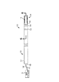
図5は、例示的な別の実施形態によるマッピング・ガイドワイヤ132を示す斜視図である。図5の実施形態において、ガイドワイヤ132は、基端部136および先端部138を有する中空の管状部材ハウジング134を備える。基端部136は、臨床医が手動で身体の外側の位置から、ローラ/ステッパ機構84の補助で、および/または他の好適な手段によって操作されうる。次いで、ガイドワイヤ132の先端部138は、1つまたは複数の標的ペーシング部位への横断を容易にするように構成される。
FIG. 5 is a perspective view illustrating a
図5の実施形態では、管状部材ハウジング134の先端部138は、体内の心臓電気活動のセンシングを行うように構成された1つまたは複数の電極140、142を備える。電極140、142は、導電性材料から作られ、管状部材ハウジング134の先端部138から基端150まで延在する複数の導線を介して信号アナライザ78に電気的に結合される。ガイドワイヤ132の先端部138上に配置された放射線不透過性マーカ154は、ガイドワイヤの送達を円滑にし、体内の電極140、142の配置を測定するために使用されうる。
In the embodiment of FIG. 5, the
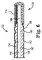
図6は、図5の6−6線に沿って切り取ったマッピング・ガイドワイヤ132の先端部を示す断面図である。図6を見るとさらにわかるように、またいくつかの実施形態において、管状部材ハウジング134は、電極(例えば、基端側電極142)および信号アナライザ78の一方に接続された導線146を収納する内腔144を備える。次いで、ハウジング134は、導電性材料から形成することができ、別の電極(例えば、先端側電極140)および信号アナライザ78に導線147を介して電気的に結合される。ハウジング134の周りに配設された絶縁層148は、周囲の体組織からガイドワイヤ132を電気的に絶縁する。絶縁148の一部は、電極140、142のそれぞれの配置で露出される。
6 is a cross-sectional view showing the distal end portion of the
使用時に、電極140、142は、体内の心臓電気活動のセンシングを行い、心電図活動信号88を分析のため信号アナライザ78に送信するように構成される。いくつかの実施形態では、電極140、142はそれぞれ、双極モードで動作する。代替えとして、また他の実施形態において、電極140、142はそれぞれ、単極モードで動作し、別の埋め込まれているリード上の基準電極、パルス発生器、カテーテル、または他の基準デバイスが、電極140、142に対する陽極として働く。いくつかの実施形態では、放射線不透過性マーカ・バンド154は、ガイドワイヤの送達を円滑にし、および/または体内の電極140、142の配置を測定するために臨床医が使用することができる。
In use, the
図7は、例示的な別の実施形態によるマッピング・ガイドワイヤ212を示す斜視図である。図7の実施形態において、ガイドワイヤ212は、基端部216および先端部218を有する中空の管状部材ハウジング214を備える。基端部216は、臨床医が手動で身体の外側の位置から、ローラ/ステッパ機構84の補助で、および/または他の好適な手段によって操作されうる。次いで、ガイドワイヤ212の先端部218は、1つまたは複数の標的ペーシング部位への横断を容易にするように構成される。
FIG. 7 is a perspective view illustrating a
図7の実施形態では、管状部材ハウジング214の先端部218は、体内の心臓電気活動のセンシングを行うように構成された一対の電極220、222を備える。管状部材ハウジング214の基端部216上の類似の一組の電極220、222が、マッピング・ガイドワイヤ212を信号アナライザ78に電気的に接続するために設けられている。ガイドワイヤ212の先端228上に配置された放射線不透過性マーカ226は、ガイドワイヤの送達を円滑にし、体内の先端側の一対の電極220、222の配置を測定するために使用されうる。
In the embodiment of FIG. 7, the
図8は、図7の8−8線に沿って切り取ったマッピング・ガイドワイヤ212の先端部218を示す断面図である。図8を見るとさらにわかるように、またいくつかの実施形態において、管状状ハウジング214は、少なくとも一部は外側部材232によって囲まれている内側コア部材230を備える。内側コア部材230は、導電性材料からなり、非導電性絶縁体234によって囲まれている。外側コア部材232も、導電性材料からなり、非導電性絶縁体236によって囲まれている。コア部材230を囲む絶縁体234の一部238は、露出しており、ハウジング214に沿って第1の電極220を形成する。外側部材232を囲む絶縁体236の一部240も、露出しており、ハウジング214に沿って第2の電極222を形成する。
FIG. 8 is a cross-sectional view showing the
使用時に、電極220、222は、体内の心臓電気活動のセンシングを行い、心電図活動信号を分析のため信号アナライザ78に送信するように構成される。いくつかの実施形態では、電極220、222はそれぞれ、双極モードで動作する。代替えとして、また他の実施形態において、電極220、222はそれぞれ、単極モードで動作し、別の埋め込まれているリード上の基準電極、パルス発生器、カテーテル、または他の基準デバイスが、電極220、222に対する陽極として働く。
In use, the
図9A〜9Bは、例示的な一実施形態によるリード・ペーシング部位を選択するための例示的な方法156を示すフローチャートである。いくつかの実施形態では、方法156は、図2の心臓リード埋め込みシステム74を使用してCRTリード14、16を埋め込む1つまたは複数の最適な部位を選択するために使用されうる複数の工程からなるものとしてよい。他の実施形態では、方法156を使用して、他の種類の心臓治療デバイスおよび/またはリードを心内膜リードまたは心外膜リードなどの体内の他の場所に埋め込むことができる。方法156は、神経刺激ペーシング・リードなどの他の心臓以外のリードを埋め込むためにも使用されうる。
9A-9B are flowcharts illustrating an
方法156は、一般的に、工程158および160から開始するものとしてよく、そこでは、導入器を使用して血管に経皮的に接近し、次いで、カテーテル(例えば、ガイド・カテーテル)を使用して、カニューレを体内の特定の場所に挿入し、これより、マッピング・ガイドワイヤ76、132、212および/または他のデバイスを後から体内に挿入し、1つまたは複数の標的ペーシング部位に送ることができる。いくつかの実施形態では、例えば、伸縮自在の導入器カテーテルを体内の経皮的アクセス部位(例えば、頸静脈または大腿動脈)に挿入し、体内の特定の場所に送り、第2の計装(例えば、ガイド・カテーテルまたはガイドワイヤ)が血管または心腔内にカニューレを挿入できるようにする。心臓の左心室または左心房にCRT治療を施すために心静脈内に埋め込む心臓リード14の埋め込みの際に、例えば、導入器を体内に経皮的に挿入し、右心房に送ることができる。カテーテルを使用して、冠静脈洞入口部などの体内の特定の場所にカニューレを挿入することができる。このカニューレ挿入は、冠状静脈洞ならびに心臓の左側に隣接して配置されている冠状静脈洞、大心臓静脈の枝、または他の心臓血管枝内に挿入すべき第2の内側カテーテル、マッピング・ガイドワイヤ76、132、212、および/または1つまたは複数の他の計装の経路を構成する。
カニューレ挿入後、第2の内側カテーテルをカテーテルに通して挿入し、体内の第1の血管枝を部分選択する(ブロック160)ことができる。いくつかの実施形態では、例えば、カテーテルの内腔を通して挿入するように構成された第2のカテーテルを心静脈後枝または心静脈中枝などの冠状静脈洞の血管枝内の体内の第2の配置に送ることができる。静脈が部分選択された後、マッピング・ガイドワイヤ76、132、212を内側カテーテルに通して静脈枝内の特定の配置に挿入する。信号アナライザ78は、マッピング・ガイドワイヤ76、132、212に接続されており、ベースラインの測定結果が収集される(ブロック162)。いくつかの実施形態では、例えば、ガイドワイヤ76、132、212上でインピーダンス・テストを実行して、ガイドワイヤと信号アナライザ78との電気的接続が適切であることを確認する。次いで、マッピング・ガイドワイヤ76、132、212を第2のカテーテルに通して第1の血管枝内の標的ペーシング部位に送る(ブロック164)。
After cannulation, a second inner catheter can be inserted through the catheter to partially select the first vessel branch in the body (block 160). In some embodiments, for example, a second catheter configured to be inserted through the lumen of the catheter is second in the body within a vascular branch of the coronary sinus, such as a posterior or intermediate ventricular vein. Can be sent to the deployment. After the vein is partially selected, the
次いで、第1の血管枝内に配置された後、信号アナライザ78は、標的部位での心臓電気的活動のセンシングを行うためにガイドワイヤ電極のうちの1つまたは複数を利用することができる(ブロック166)。マッピング・ガイドワイヤ76、132、212によってセンシングされた心電図活動信号88は、信号アナライザ78に供給される(ブロッ
ク168)。いくつかの実施形態では、別の埋め込まれたリードまたは表面EKGなどの基準デバイス90も、右心房または右心室などの体内の異なる場所で心臓電気活動のセンシングを行い(ブロック170)、信号アナライザ78に、基準心電図信号92を供給する(ブロック172)。
Then, after being placed in the first vessel branch, the
分析モジュール86は、電気的活動信号88および場合によっては基準信号92も比較し、これらの信号88、92から、特定の部位がリードを埋め込みに最適な部位であるかどうかを判定するために後から使用できるタイミング間隔を計算する(ブロック174)。いくつかの実施形態では、分析モジュール86は、心室分極の第1の偏向(例えば、Q1またはQ)および最大偏向(例えば、LV)を測定することによって心室脱分極に関連するタイミング間隔を計算する。測定することができる他のタイミング間隔の例としては、RV−LV、RA−LV、Q*−LVなどが挙げられる。
The analysis module 86 also compares the
標的ペーシング部位で、1つまたは複数の心電図測定を行った後、臨床医は、次に、血管枝内のマッピング・ガイドワイヤ76、132、212を後退させ、ガイドワイヤ76、132、212を血管の原点に近い位置にある血管枝内の別の場所に再配置する(ブロック176)。ガイドワイヤ76、132、212が後退させられるときに、信号アナライザ78は、それぞれの追加の標的部位に対するタイミング間隔を計算するように構成されうる(ブロック178)。
After performing one or more electrocardiogram measurements at the target pacing site, the clinician then retracts the
信号アナライザ78は、1つまたは複数の前の標的部位で測定されたタイミング間隔と突き合わせて現在の標的ペーシング部位で測定されたタイミング間隔(例えば、Q−LV)を比較して、現在の部位がリード埋め込みの最適な部位であるかどうかを判定することができる(ブロック180)。他のタイミング間隔も、特定の部位が最適な部位であるかどうかを判定するために使用されうる。他のパラメータも、タイミング間隔に加えて、またはタイミング間隔の代わりに、現在のペーシング部位が最適であるかどうかを判定するために使用できる。いくつかの実施形態では、例えば、ガイドワイヤ76、132、212は、特定の部位におけるペーシング振幅閾値のセンシングを行うことができ、次いで、これを他の場所でセンシングが行われた振幅閾値および/または所定の閾値と比較して、現在の部位が最適であるかどうかを判定することができる。横隔神経刺激の確率などの他の特性も、現在のペーシング部位が最適であるかどうかを判定するために使用できる。
The
いくつかの実施形態では、センシングが行われるタイミング間隔を閾値と比較して、候補ペーシング部位が最適であるかどうかを判定することができる。比較に使用される閾値は、典型的には、センシングが行われた特定のタイミング間隔に応じて異なる。例えば、Q−LVまたはQ1−LVのタイミング間隔では、部位が最適であるかどうかを判定するための閾値は、80ms以上に設定するとよい。逆に、Q*−LVタイミング間隔を使用する遠距離場センシングでは、より高い閾値(例えば、100ms)を使用して、特定の部位が最適な部位であるかどうかを判定することができる。与えられたタイミング間隔に対する特定の閾値基準は、典型的には、患者の心室脱分極特性に応じて変化し、したがって、患者毎に異なる。 In some embodiments, the timing interval at which sensing is performed can be compared to a threshold value to determine if the candidate pacing site is optimal. The threshold used for comparison typically varies depending on the particular timing interval at which sensing was performed. For example, in the Q-LV or Q1-LV timing interval, the threshold value for determining whether or not the region is optimal may be set to 80 ms or more. Conversely, in far field sensing using the Q * -LV timing interval, a higher threshold (eg, 100 ms) can be used to determine whether a particular site is the optimal site. The particular threshold criteria for a given timing interval typically varies depending on the patient's ventricular depolarization characteristics and thus varies from patient to patient.
それぞれの血管枝について標的ペーシング部位をテストする方法を実行する際に、信号アナライザ78が、標的ペーシング部位の1つが最適な部位であると検知した場合(ブロック182)、信号アナライザ78は、潜在的埋め込み部位が存在することを(例えば、ユーザ・インターフェース94を介して)臨床医に警告し、臨床医がその部位をリード電極に対する可能な埋め込み部位としてみなすよう促す(ブロック188)。いくつかの実施形態では、例えば、信号アナライザ78は、現在の部位のタイミング間隔が1つまたは複数の前の標的部位で測定した値より大きい場合に現在の部位が最適な部位であると臨床医に警告することができる。他の実施形態では、信号アナライザ78は、タイミング間隔
が1つまたは複数の前の標的部位で測定した値より大きく、現在のタイミング間隔がタイミング間隔閾値を超えている場合に現在の部位が最適な部位であると臨床医に警告することができる。
In performing the method of testing target pacing sites for each vessel branch, if
臨床医が、決定ブロック182において、標的ペーシング部位のどれも最適でないと判定した場合、または臨床医が、リードの挿入に関して他の血管枝を考えたい場合に、臨床医は、マッピング・ガイドワイヤ76、132、212を引き出してカテーテル内に戻し、テストのため別の血管枝を選択することができる(ブロック184)。例えば、テストされた第1の血管枝が、心静脈後枝であり、信号アナライザ78が、最適である標的ペーシング部位がなかったと判定した場合、臨床医は、マッピング・ガイドワイヤ76、132、212を後退させてカテーテル内に戻し、第1の血管枝に対して実行されたのと似た手法でテストするためにもっと外側の血管枝にカテーテル/ガイドワイヤを送ることができる。次いで、この方法を1回または複数回繰り返して、追加の血管枝を分析することができる。
If the clinician determines at
次いで、臨床医はリードをその部位に埋め込むか(ブロック189)、または他の潜在的ペーシング部位を考えるために他の血管枝を選択する方法を継続することができる。部位の選択が終わった後、リードをガイドワイヤ76、132、212に載せてその部位に送ることができる。次いで、埋め込まれたリードを血管内に固定し、PSA100および/またはプログラマ102を使用してテストし、選択された部位が結果として活動を生じることを確認することができる。次いで、必要ならば、方法156を繰り返して、体内に他のリードを埋め込むために適している他の部位を決定することができる。選択された埋め込み部位に関連するタイミング間隔に基づくペーシング出力構成の選択を含む、治療デバイス10をプログラムするために他の追加の工程も実行することができる。
The clinician can then embed the lead at that site (block 189) or continue with the method of selecting other vessel branches to consider other potential pacing sites. After the site selection is complete, the lead can be placed on the
図10〜15は、図2のリード埋め込みシステム74を使用して冠状静脈枝内のリード・ペーシング部位を選択するために使用される複数の例示的な工程を示すいくつかの図である。図10〜15は、例えば、図9A〜9Bに関して本明細書で説明されている方法156を使用してリード・ペーシング部位を選択するために使用されうるいくつかの例示的な工程を表すものとしてよい。しかし、体内の標的領域の選択は、特定の用途に応じて、図示されているものと異なることがある。
FIGS. 10-15 are several diagrams illustrating multiple exemplary steps used to select a lead pacing site in a coronary vein branch using the
図10に示されている第1の工程では、カテーテル190は、冠静脈洞入口部40内に挿入され、これにより、冠状静脈洞42にカニューレが挿入される。カニューレが挿入された後、図11の第2の工程でさらに示されているように、第2のカテーテル192をカテーテル190内に挿入し、図示されているように、カテーテル190の先端194を超えて冠状静脈後枝196などの体内の第1の血管枝に送ることができる。しかし、選択された特定の血管枝は、血管のサイズ、血管枝内にカテーテル192を挿入することの容易さ、さらには他の要因に応じて異なりうる。第2のカテーテル192内の内腔198は、図11に示されているように血管枝196内にカテーテル192が配置された後カテーテル192の先端200を超えて先端側に送ることができるマッピング・ガイドワイヤ(例えば、ガイドワイヤ76)を運ぶように構成されうる。
In the first step shown in FIG. 10, the
いくつかの実施形態では、図11に示されているように、マッピング・ガイドワイヤ76は血管枝196内の第1の場所202に送られ、信号アナライザ78に、上で説明されているように、その場所で1回または複数回の心電図測定を行い、特定の部位が最適であるかどうかを判定するために使用されうるタイミング間隔を計算することを行わせる。次いで、臨床医は、図12にさらに示されているように血管枝196内の追加の電気的測定を行うことを続けながらガイドワイヤ76を血管枝196の底部204に向けて一定距離だけ基端側に後退させることができる。いくつかの実施形態では、ガイドワイヤ76が血
管枝196内に後退させられるときに測定を連続的に行うことができる。他の実施形態では、血管枝196内の1つまたは複数の特定の配置で測定を連続的に行うことができる。いくつかの実施形態では、ローラ/ステッパ機構84または他の好適なサーボ機構を使用して、電気的測定を行うときに信号アナライザ78に体内のガイドワイヤ76の正確な配置を供給することができる。
In some embodiments, as shown in FIG. 11, the
臨床医が異なる埋め込み部位を選択することを望んでいる場合、臨床医は、ガイドワイヤ76をカテーテル192内に基端側に後退させて、テストする別の血管枝を選択することができる。いくつかの実施形態では、また図13の別の工程を見るとわかるように、例えば、ガイドワイヤ76を運ぶカテーテル192を中外側血管枝などの第2のより外側の血管枝206に送ることができ、ガイドワイヤ76を、再び、カテーテル192の先端200を超えて先端側に、第2の血管枝206内の第1の場所208に送り、そこで、その場所208で電気的測定値のセンシングを行うことができる。次いで、図14の別の工程を見るとさらにわかるように、1回または複数回の追加の電気的測定を行いながらガイドワイヤ76を血管枝206の底部210に向けて基端側に後退させる方法を第2の血管枝206内で実行することができる。いくつかの実施形態では、臨床医は、ペーシング・パルスをガイドワイヤ電極にさらに印加し、特定のペーシング部位がペーシング刺激に反応し、その結果活性化するかどうかを判定することができる。必要ならば、体内の追加の血管枝(複数可)について、他の最適な部位を決定する方法を実行することができる。
If the clinician wishes to select a different implantation site, the clinician can retract the
部位が選択された後、図15の別の工程にさらに示されているように、臨床医は、次に、リード16をマッピング・ガイドワイヤ76の上に載せて提案されている部位に送ることができる。追加のテストも、ペーシング・システム・アナライザ(PSA)と連携して実行し、捕捉振幅、インピーダンスなどのリード特性を決定することができる。いくつかの実施形態では、マッピング・ガイドワイヤ76を使用して、心臓の一時的ペーシングを行って、その部位に関連するペーシング閾値を決定することができる。次いで、マッピング・ガイドワイヤ76およびカテーテル190、192を身体から取り外して、体内に埋め込まれる追加のリードについてこの方法を繰り返すことができる。
After the site is selected, the clinician then places the
本発明の範囲から逸脱することなく、さまざまな修正および追加を説明されている例示的な実施形態に加えることができる。例えば、上述の実施形態は、特定の特徴を指しているが、本発明の範囲は、特徴の異なる組み合わせを有する実施形態および説明されている特徴のすべてを含むわけではない実施形態も含む。したがって、本発明の範囲は、請求項の範囲内に収まるようなすべてのそのような代替、修正、および変更形態を、そのすべての等価形態と一緒に、包含することが意図されている。 Various modifications and additions can be made to the described exemplary embodiments without departing from the scope of the present invention. For example, although the embodiments described above refer to particular features, the scope of the invention includes embodiments that have different combinations of features and embodiments that do not include all of the described features. Accordingly, the scope of the present invention is intended to embrace all such alternatives, modifications and variations that fall within the scope of the claims, along with all their equivalents.
Claims (17)
マッピング・ガイドワイヤであって、基端部と先端部とを有し、先端部は体内の心臓電気活動のセンシングを行うように構成された1つ以上の電極を備え、導電性材料からなる中実なコアワイヤの周りに配設された絶縁体を備え、前記各電極は前記中実なコアワイヤの露出部分を含む、マッピング・ガイドワイヤと、
信号アナライザであって、前記マッピング・ガイドワイヤによってセンシングが行われた心電図活動信号を分析するように構成された分析モジュールを備え、該センシングが行われた心電図活動信号に少なくとも基づき心室脱分極に関連するタイミング間隔を決定するように構成された、信号アナライザと、
前記体内におけるタイミング間隔を監視するように構成されたユーザ・インターフェースと、を備えるシステム。 In cardiac lead implantation system,
A mapping guidewire having a proximal end and a distal end, the distal end comprising one or more electrodes configured to sense cardiac electrical activity in the body and comprising a conductive material A mapping guidewire comprising an insulator disposed around a solid core wire, each electrode including an exposed portion of the solid core wire;
A signal analyzer comprising an analysis module configured to analyze an electrocardiogram activity signal sensed by the mapping guidewire and related to ventricular depolarization based at least on the sensed electrocardiogram activity signal A signal analyzer configured to determine a timing interval to be
A user interface configured to monitor timing intervals in the body.
表示するための手段を備える請求項6に記載のシステム。 7. The system of claim 6 , wherein the display module comprises means for visually displaying timing interval measurement results on a display screen.
導電性材料からなる中実なコアワイヤの周りに配設された1つ以上の絶縁部材を備える長尺状の本体部と、
心臓電気活動のセンシングを行うように構成された1つ以上の電極であって、前記中実なコアワイヤの露出部分を含む、1つ以上の電極と、
ガイドワイヤを信号アナライザに電気的に結合するための手段と、を備えるマッピング・ガイドワイヤ。 A mapping guide wire,
An elongate body comprising one or more insulating members disposed around a solid core wire of conductive material ;
One or more electrodes configured to sense cardiac electrical activity, the one or more electrodes comprising an exposed portion of the solid core wire ;
A mapping guidewire comprising: means for electrically coupling the guidewire to the signal analyzer.
該システムは、
基端部と先端部とを有し、先端部は1つ以上の電極を備え、導電性材料からなる中実なコアワイヤの周りに配設された絶縁体を備え、前記各電極は前記中実なコアワイヤの露出部分を含む、マッピング・ガイドワイヤと、
前記マッピング・ガイドワイヤによってセンシングが行われた心電図活動信号を分析するように構成された分析モジュールを備える信号アナライザと、
前記体内におけるタイミング間隔を監視するように構成されたユーザ・インターフェースとを備え、
患者に対して、
第1のカテーテルが体内に挿入され、冠状静脈洞にカニューレが挿入されており、
該第1のカテーテルに通して第2のカテーテルが心臓または心臓の近くの第1の血管枝内に送り込まれており、
該第2のカテーテルに通して前記マッピング・ガイドワイヤが該第1の血管枝内の第1の場所に送り込まれている状態において、前記心臓リード埋め込みシステムが、
該第1の血管枝内の第1の標的ペーシング部位で1つ以上の電気的測定値のセンシングを行うことと、
該マッピング・ガイドワイヤが該第1の血管枝内の1つまたは複数の追加の標的ペーシング部位に移動されたときに、心電図活動信号を信号アナライザに送信することと、
各追加の標的ペーシング部位で1つまたは複数の追加の電気的測定値のセンシングを行い、1つ以上の追加の心電図活動信号を該信号アナライザに送信することと、
該第1の血管枝における該標的ペーシング部位のうちの1つ以上が最適な部位であるかどうかを判定することと、を備える作動方法。 A method of operating a cardiac lead implantation system for selecting a cardiac lead pacing site in a body comprising:
The system
A proximal end portion and a distal end portion, the distal end portion including one or more electrodes, and an insulator disposed around a solid core wire made of a conductive material, wherein each of the electrodes is the solid A mapping guide wire including an exposed portion of the core wire,
A signal analyzer comprising an analysis module configured to analyze an electrocardiogram activity signal sensed by the mapping guidewire;
A user interface configured to monitor timing intervals in the body;
For patients
First catheter is inserted into the body, and a cannula is inserted into the coronary sinus,
Second catheter cage sends write Marete within the first branch vessel near the heart or the heart through the first catheter,
In the state wherein the mapping guidewire through the catheter the second is rarely write sent to the first location in the branch vessel of the first, the cardiac lead embedded system,
Sensing one or more electrical measurements at a first target pacing site in the first vascular branch;
Sending an electrocardiogram activity signal to a signal analyzer when the mapping guidewire is moved to one or more additional target pacing sites in the first vessel branch;
Sensing one or more additional electrical measurements at each additional target pacing site and transmitting one or more additional electrocardiogram activity signals to the signal analyzer;
Operating method comprising the that one or more of the target pacing site in a blood vessel branch of the first to determine whether the optimal site, the.
前記標的ペーシング部位で心室脱分極に関連するタイミング間隔を測定することと、
前記タイミング間隔を1つまたは複数の他のタイミング間隔、またはタイミング間隔閾値と比較することとを含む請求項11に記載の作動方法。 Determining whether one or more of the target pacing sites is an optimal site is by the signal analyzer,
Measuring a timing interval associated with ventricular depolarization at the target pacing site;
The operating method as claimed in claim 11, and comparing said timing interval of one or more other timing intervals or timing interval threshold.
前記1つ以上の電極により、前記体内における基準電気的測定値のセンシングを行い、基準心電図信号を前記信号アナライザに送信することと、
前記信号アナライザにより、前記標的ペーシング部位における前記センシングが行われた心電図活動信号と前記基準心電図信号とに基づき心室脱分極に関連するタイミング間隔を決定することと、
前記信号アナライザにより、前記タイミング間隔を1つまたは複数の他のタイミング間隔、またはタイミング間隔閾値と比較することとを含む請求項11に記載の作動方法。 Determining whether at least one of the target pacing sites is an optimal site is
Sensing a reference electrical measurement in the body with the one or more electrodes and transmitting a reference electrocardiogram signal to the signal analyzer;
Determining, by the signal analyzer, a timing interval associated with ventricular depolarization based on the sensed electrocardiogram activity signal at the target pacing site and the reference electrocardiogram signal;
Wherein the signal analyzer, the method of operation according to claim 11, and comparing said timing interval of one or more other timing intervals or timing interval threshold.
該1つ以上の追加の血管枝内の1つまたは複数の標的ペーシング部位において1つ以上の電気的測定値のセンシングを行うことと、
1つ以上のタイミング間隔を測定することによって該1つ以上の追加の血管枝内のける1つ以上の標的ペーシング部位が最適な部位であるかどうかを判定することとをさらに備える請求項11に記載の作動方法。 With the catheter and mapping guidewire inserted into one or more additional vessel branches,
Sensing one or more electrical measurements at one or more target pacing sites in the one or more additional vessel branches;
12. The method of claim 11 , further comprising determining whether one or more target pacing sites in the one or more additional vessel branches are optimal sites by measuring one or more timing intervals. The operating method described.
Applications Claiming Priority (3)
| Application Number | Priority Date | Filing Date | Title |
|---|---|---|---|
| US41522110P | 2010-11-18 | 2010-11-18 | |
| US61/415,221 | 2010-11-18 | ||
| PCT/US2011/060165 WO2012067935A1 (en) | 2010-11-18 | 2011-11-10 | Guidewire and signal analyzer for pacing site optimization |
Publications (2)
| Publication Number | Publication Date |
|---|---|
| JP2013536743A JP2013536743A (en) | 2013-09-26 |
| JP5640149B2 true JP5640149B2 (en) | 2014-12-10 |
Family
ID=45218858
Family Applications (1)
| Application Number | Title | Priority Date | Filing Date |
|---|---|---|---|
| JP2013527379A Expired - Fee Related JP5640149B2 (en) | 2010-11-18 | 2011-11-10 | Guidewire and signal analyzer for pacing site optimization |
Country Status (4)
| Country | Link |
|---|---|
| US (1) | US9031647B2 (en) |
| EP (1) | EP2640457A1 (en) |
| JP (1) | JP5640149B2 (en) |
| WO (1) | WO2012067935A1 (en) |
Families Citing this family (17)
| Publication number | Priority date | Publication date | Assignee | Title |
|---|---|---|---|---|
| US20140039312A1 (en) * | 2012-08-02 | 2014-02-06 | Cardiac Pacemakers, Inc. | Pacing-site selection for lead placement |
| JP6396923B2 (en) * | 2012-12-31 | 2018-09-26 | ボルケーノ コーポレイション | Intravascular device, system and method |
| US9351783B2 (en) | 2013-05-01 | 2016-05-31 | Medtronic Cryocath Lp | Diagnostic guidewire for cryoablation sensing and pressure monitoring |
| EP2810686B1 (en) * | 2013-06-04 | 2016-03-23 | Sorin CRM SAS | Assembly suitable for implantation in the coronary venous network for stimulation of a left heart chamber |
| FR3034642B1 (en) * | 2015-04-07 | 2021-01-15 | Benjamin Faurie | INTRODUCTOR FOR A HEART VALVE REPLACEMENT KIT OR FOR CORONARY ANGIOPLASTY KIT |
| WO2017070322A1 (en) * | 2015-10-21 | 2017-04-27 | Toth, Landy | Controlled and precise treatment of cardiac tissues |
| CN106621047B (en) * | 2015-10-29 | 2020-06-16 | 创领心律管理医疗器械(上海)有限公司 | Active cardiac electrical lead |
| ES2947184T3 (en) * | 2016-03-18 | 2023-08-02 | Teleflex Life Sciences Ltd | stimulation guide |
| ES2892273T3 (en) * | 2016-10-07 | 2022-02-03 | Electroducer | Heart valve replacement kit or coronary angioplasty kit |
| FR3057155B1 (en) * | 2016-10-07 | 2020-11-27 | Benjamin Faurie | BIPOLAR WIRE GUIDE FOR HEART VALVE REPLACEMENT KIT OR CORONARY ANGIOPLASTY KIT INCLUDING DELIVERY CATHETER OR INTRODUCER |
| JP7229771B2 (en) * | 2016-11-30 | 2023-02-28 | フクダ電子株式会社 | Electrocardiogram display method and electrocardiogram analyzer |
| US10953204B2 (en) | 2017-01-09 | 2021-03-23 | Boston Scientific Scimed, Inc. | Guidewire with tactile feel |
| US11647935B2 (en) * | 2017-07-24 | 2023-05-16 | St. Jude Medical, Cardiology Division, Inc. | Masked ring electrodes |
| US10918870B2 (en) * | 2018-03-07 | 2021-02-16 | Medtronic, Inc. | Atrial lead placement for treatment of atrial dyssynchrony |
| US11951319B2 (en) * | 2018-08-07 | 2024-04-09 | Pacesetter, Inc. | Systems and methods for applying anti-tachycardia pacing using subcutaneous implantable cardioverter-defibrillators |
| US11844912B2 (en) * | 2019-08-23 | 2023-12-19 | Thabet Alsheikh | Method for visualizing a catheterization guidewire |
| US20210138239A1 (en) | 2019-09-25 | 2021-05-13 | Swift Sync, Llc | Transvenous Intracardiac Pacing Catheter |
Family Cites Families (24)
| Publication number | Priority date | Publication date | Assignee | Title |
|---|---|---|---|---|
| US5699796A (en) * | 1993-01-29 | 1997-12-23 | Cardima, Inc. | High resolution intravascular signal detection |
| WO1995009561A1 (en) | 1993-10-01 | 1995-04-13 | Target Therapeutics, Inc. | Sheathed multipolar catheter and multipolar guidewire for sensing cardiac electrical activity |
| US5517989A (en) | 1994-04-01 | 1996-05-21 | Cardiometrics, Inc. | Guidewire assembly |
| US6144880A (en) | 1998-05-08 | 2000-11-07 | Cardiac Pacemakers, Inc. | Cardiac pacing using adjustable atrio-ventricular delays |
| US6453192B1 (en) | 2000-03-13 | 2002-09-17 | Cardiac Pacemakers, Inc. | Detection of ventricular ectopic beats using ventricular electrogram |
| US6993389B2 (en) | 2001-03-30 | 2006-01-31 | Cardiac Pacemakers, Inc. | Identifying heart failure patients suitable for resynchronization therapy using QRS complex width from an intracardiac electrogram |
| JP4222775B2 (en) | 2001-06-15 | 2009-02-12 | ラディ・メディカル・システムズ・アクチェボラーグ | Measuring device that can be inserted into living organisms |
| US7113823B2 (en) | 2001-10-26 | 2006-09-26 | Cardiac Pacemakers, Inc. | Morphology-based optimization of cardiac resynchronization therapy |
| US20040024425A1 (en) | 2002-07-31 | 2004-02-05 | Worley Seth J. | Method and apparatus for using a cardiac stimulating, sensing and guidewire combination |
| US6923772B2 (en) | 2002-09-06 | 2005-08-02 | Cardiac Pacemakers, Inc. | Apparatus and method for determining responders to cardiac resynchronization therapy using implantable accelerometers |
| US7142922B2 (en) | 2002-12-20 | 2006-11-28 | Cardiac Pacemakers, Inc. | Method and apparatus for predicting acute response to cardiac resynchronization therapy at a given stimulation site |
| US8103358B2 (en) * | 2003-04-04 | 2012-01-24 | Medtronic, Inc. | Mapping guidelet |
| US7123960B2 (en) | 2003-12-22 | 2006-10-17 | Cardiac Pacemakers, Inc. | Method and system for delivering cardiac resynchronization therapy with variable atrio-ventricular delay |
| US20050165324A1 (en) * | 2004-01-26 | 2005-07-28 | Rogier Receveur | System and method for using sensors to identify an anatomical position |
| US7347751B2 (en) | 2004-09-30 | 2008-03-25 | Cardiac Pacemakers, Inc. | Cardiac lead implantation system |
| WO2006105474A2 (en) | 2005-03-31 | 2006-10-05 | Proteus Biomedical, Inc. | Automated optimization of multi-electrode pacing for cardiac resynchronization |
| US7751882B1 (en) * | 2005-12-21 | 2010-07-06 | Pacesetter, Inc. | Method and system for determining lead position for optimized cardiac resynchronization therapy hemodynamics |
| US9717468B2 (en) * | 2006-01-10 | 2017-08-01 | Mediguide Ltd. | System and method for positioning an artificial heart valve at the position of a malfunctioning valve of a heart through a percutaneous route |
| US7890172B2 (en) | 2007-01-18 | 2011-02-15 | Cardiac Pacemakers, Inc. | Pacing output configuration selection for cardiac resynchronization therapy patients |
| US8155756B2 (en) * | 2007-02-16 | 2012-04-10 | Pacesetter, Inc. | Motion-based optimization for placement of cardiac stimulation electrodes |
| US20080243195A1 (en) | 2007-03-30 | 2008-10-02 | Sommer John L | Mapping guidelet |
| US9037239B2 (en) | 2007-08-07 | 2015-05-19 | Cardiac Pacemakers, Inc. | Method and apparatus to perform electrode combination selection |
| JP5403785B2 (en) | 2008-10-15 | 2014-01-29 | 国立大学法人 名古屋工業大学 | Insertion device |
| US8527049B2 (en) | 2008-12-11 | 2013-09-03 | Pacesetter, Inc. | Cardiac resynchronization therapy optimization using vector measurements obtained from realtime electrode position tracking |
-
2011
- 2011-11-10 JP JP2013527379A patent/JP5640149B2/en not_active Expired - Fee Related
- 2011-11-10 WO PCT/US2011/060165 patent/WO2012067935A1/en active Application Filing
- 2011-11-10 EP EP11793897.7A patent/EP2640457A1/en not_active Withdrawn
- 2011-11-10 US US13/293,707 patent/US9031647B2/en active Active
Also Published As
| Publication number | Publication date |
|---|---|
| JP2013536743A (en) | 2013-09-26 |
| US9031647B2 (en) | 2015-05-12 |
| US20120130220A1 (en) | 2012-05-24 |
| WO2012067935A1 (en) | 2012-05-24 |
| EP2640457A1 (en) | 2013-09-25 |
Similar Documents
| Publication | Publication Date | Title |
|---|---|---|
| JP5640149B2 (en) | Guidewire and signal analyzer for pacing site optimization | |
| US20210069491A1 (en) | Implantable medical device fixation | |
| US8346372B2 (en) | Motion-based optimization for placement of cardiac stimulation electrodes | |
| US6671550B2 (en) | System and method for determining location and tissue contact of an implantable medical device within a body | |
| US8560068B2 (en) | Medical device for stimulation of the HIS bundle | |
| EP0473070B1 (en) | Cardiac pacing systems with tensiometry | |
| US8594792B2 (en) | Implantable lead and coronary venous pressure sensor apparatus and method | |
| US20160228715A9 (en) | Implantable medical device fixation | |
| JP2008532638A5 (en) | ||
| US10195442B2 (en) | Methods and systems for multi-site pacing | |
| US11911623B2 (en) | Implantable medical electrode assemblies, devices, systems, kits, and methods | |
| US11786741B2 (en) | Systems and methods for implanting a medical device using an active guidewire | |
| US20120203295A1 (en) | Pacing site optimization using paced interventricular delays |
Legal Events
| Date | Code | Title | Description |
|---|---|---|---|
| A621 | Written request for application examination |
Free format text: JAPANESE INTERMEDIATE CODE: A621 Effective date: 20130228 |
|
| A131 | Notification of reasons for refusal |
Free format text: JAPANESE INTERMEDIATE CODE: A131 Effective date: 20140212 |
|
| A521 | Request for written amendment filed |
Free format text: JAPANESE INTERMEDIATE CODE: A523 Effective date: 20140509 |
|
| TRDD | Decision of grant or rejection written | ||
| A01 | Written decision to grant a patent or to grant a registration (utility model) |
Free format text: JAPANESE INTERMEDIATE CODE: A01 Effective date: 20141007 |
|
| A61 | First payment of annual fees (during grant procedure) |
Free format text: JAPANESE INTERMEDIATE CODE: A61 Effective date: 20141027 |
|
| R150 | Certificate of patent or registration of utility model |
Ref document number: 5640149 Country of ref document: JP Free format text: JAPANESE INTERMEDIATE CODE: R150 |
|
| R250 | Receipt of annual fees |
Free format text: JAPANESE INTERMEDIATE CODE: R250 |
|
| R250 | Receipt of annual fees |
Free format text: JAPANESE INTERMEDIATE CODE: R250 |
|
| R250 | Receipt of annual fees |
Free format text: JAPANESE INTERMEDIATE CODE: R250 |
|
| R250 | Receipt of annual fees |
Free format text: JAPANESE INTERMEDIATE CODE: R250 |
|
| LAPS | Cancellation because of no payment of annual fees |