JP5633938B2 - Direct forced draft cooler / cooling tower and liquid collector therefor - Google Patents
Direct forced draft cooler / cooling tower and liquid collector therefor Download PDFInfo
- Publication number
- JP5633938B2 JP5633938B2 JP2011552972A JP2011552972A JP5633938B2 JP 5633938 B2 JP5633938 B2 JP 5633938B2 JP 2011552972 A JP2011552972 A JP 2011552972A JP 2011552972 A JP2011552972 A JP 2011552972A JP 5633938 B2 JP5633938 B2 JP 5633938B2
- Authority
- JP
- Japan
- Prior art keywords
- liquid
- heat exchanger
- ridge
- housing
- exchanger means
- Prior art date
- Legal status (The legal status is an assumption and is not a legal conclusion. Google has not performed a legal analysis and makes no representation as to the accuracy of the status listed.)
- Expired - Fee Related
Links
Images


Classifications
-
- F—MECHANICAL ENGINEERING; LIGHTING; HEATING; WEAPONS; BLASTING
- F28—HEAT EXCHANGE IN GENERAL
- F28F—DETAILS OF HEAT-EXCHANGE AND HEAT-TRANSFER APPARATUS, OF GENERAL APPLICATION
- F28F25/00—Component parts of trickle coolers
- F28F25/02—Component parts of trickle coolers for distributing, circulating, and accumulating liquid
- F28F25/04—Distributing or accumulator troughs
-
- F—MECHANICAL ENGINEERING; LIGHTING; HEATING; WEAPONS; BLASTING
- F28—HEAT EXCHANGE IN GENERAL
- F28C—HEAT-EXCHANGE APPARATUS, NOT PROVIDED FOR IN ANOTHER SUBCLASS, IN WHICH THE HEAT-EXCHANGE MEDIA COME INTO DIRECT CONTACT WITHOUT CHEMICAL INTERACTION
- F28C1/00—Direct-contact trickle coolers, e.g. cooling towers
- F28C1/02—Direct-contact trickle coolers, e.g. cooling towers with counter-current only
-
- F—MECHANICAL ENGINEERING; LIGHTING; HEATING; WEAPONS; BLASTING
- F24—HEATING; RANGES; VENTILATING
- F24F—AIR-CONDITIONING; AIR-HUMIDIFICATION; VENTILATION; USE OF AIR CURRENTS FOR SCREENING
- F24F3/00—Air-conditioning systems in which conditioned primary air is supplied from one or more central stations to distributing units in the rooms or spaces where it may receive secondary treatment; Apparatus specially designed for such systems
- F24F3/12—Air-conditioning systems in which conditioned primary air is supplied from one or more central stations to distributing units in the rooms or spaces where it may receive secondary treatment; Apparatus specially designed for such systems characterised by the treatment of the air otherwise than by heating and cooling
-
- F—MECHANICAL ENGINEERING; LIGHTING; HEATING; WEAPONS; BLASTING
- F28—HEAT EXCHANGE IN GENERAL
- F28C—HEAT-EXCHANGE APPARATUS, NOT PROVIDED FOR IN ANOTHER SUBCLASS, IN WHICH THE HEAT-EXCHANGE MEDIA COME INTO DIRECT CONTACT WITHOUT CHEMICAL INTERACTION
- F28C1/00—Direct-contact trickle coolers, e.g. cooling towers
-
- F—MECHANICAL ENGINEERING; LIGHTING; HEATING; WEAPONS; BLASTING
- F28—HEAT EXCHANGE IN GENERAL
- F28D—HEAT-EXCHANGE APPARATUS, NOT PROVIDED FOR IN ANOTHER SUBCLASS, IN WHICH THE HEAT-EXCHANGE MEDIA DO NOT COME INTO DIRECT CONTACT
- F28D5/00—Heat-exchange apparatus having stationary conduit assemblies for one heat-exchange medium only, the media being in contact with different sides of the conduit wall, using the cooling effect of natural or forced evaporation
- F28D5/02—Heat-exchange apparatus having stationary conduit assemblies for one heat-exchange medium only, the media being in contact with different sides of the conduit wall, using the cooling effect of natural or forced evaporation in which the evaporating medium flows in a continuous film or trickles freely over the conduits
-
- F—MECHANICAL ENGINEERING; LIGHTING; HEATING; WEAPONS; BLASTING
- F28—HEAT EXCHANGE IN GENERAL
- F28F—DETAILS OF HEAT-EXCHANGE AND HEAT-TRANSFER APPARATUS, OF GENERAL APPLICATION
- F28F25/00—Component parts of trickle coolers
- F28F25/02—Component parts of trickle coolers for distributing, circulating, and accumulating liquid
-
- Y—GENERAL TAGGING OF NEW TECHNOLOGICAL DEVELOPMENTS; GENERAL TAGGING OF CROSS-SECTIONAL TECHNOLOGIES SPANNING OVER SEVERAL SECTIONS OF THE IPC; TECHNICAL SUBJECTS COVERED BY FORMER USPC CROSS-REFERENCE ART COLLECTIONS [XRACs] AND DIGESTS
- Y10—TECHNICAL SUBJECTS COVERED BY FORMER USPC
- Y10T—TECHNICAL SUBJECTS COVERED BY FORMER US CLASSIFICATION
- Y10T137/00—Fluid handling
- Y10T137/8593—Systems
Landscapes
- Engineering & Computer Science (AREA)
- Mechanical Engineering (AREA)
- General Engineering & Computer Science (AREA)
- Physics & Mathematics (AREA)
- Thermal Sciences (AREA)
- Chemical & Material Sciences (AREA)
- Combustion & Propulsion (AREA)
- Heat-Exchange Devices With Radiators And Conduit Assemblies (AREA)
Description
本出願は、2009年3月3日に出願された米国仮特許出願第60/208995号、2009年6月5日に出願された米国仮特許出願第61/217822号及び2009年7月13日に出願された米国仮特許出願第61/270723号の恩典を主張する。これらの出願の開示は本明細書に参照として含まれる。 This application is based on US Provisional Patent Application No. 60/208995 filed on March 3, 2009, US Provisional Patent Application No. 61/217822 filed on June 5, 2009, and July 13, 2009. Claims the benefit of US Provisional Patent Application No. 61 / 270,723, filed in the United States. The disclosures of these applications are included herein by reference.
本発明は全般的には直接強制通風液体冷却器/閉ループ冷却塔及び/または小型冷却塔に関し、さらに詳しくは、そのような冷却器及び冷却塔のための改善された散気集排水システムに関する。 The present invention relates generally to direct forced air liquid coolers / closed loop cooling towers and / or small cooling towers, and more particularly to an improved diffused collection and drainage system for such coolers and cooling towers.
従来タイプの工業用冷却塔は、水または他の液体が、塔内を上に向かって移動している空気に対向する流れとして、逆方向に、塔内を落下するかまたは下に向けて散布される、いわゆる向流塔を備える。そのようなシステムは、水/空気スクラバー、集塵装置、空冷塔、蒸発冷却器、流体冷却器または閉ループ冷却塔、蒸発凝縮器等を含む、様々な用途に用いられる。一般にそのような工業用冷却塔は、降り注ぐ水を集めるために非常に大きな底部水溜めを備える極めて大きな恒久設備である。 Traditional industrial cooling towers are a system in which water or other liquid falls in the opposite direction as a stream facing the air moving upward in the tower or is scattered downward. The so-called countercurrent tower is provided. Such systems are used in a variety of applications, including water / air scrubbers, dust collectors, air cooling towers, evaporative coolers, fluid coolers or closed loop cooling towers, evaporative condensers, and the like. In general, such industrial cooling towers are very large permanent installations with a very large bottom reservoir for collecting the pouring water.
屋上設置小型タワーのような、そのような目的のための、可搬型の比較的小さな冷却塔がいくつか、様々な用途のためにつくられている。例えば、ハロルド・ディー・カーティス(Harold D. Curtis)の特許文献1及び2は、工場で既製品として製作され、容易に搬送でき、現場で簡単に組み立てて、現場における特定の水/液体冷却または処理のプロジェクトに必要な容量を提供できる大きさの個別モジュール型冷却塔を開示している。特許文献1及び2に開示されるシステムでは、塔に空気を供給するための1つないし複数のファンが、充填/蒸発冷却材、あるいは液体冷却コイルの下側の、塔の底部に配置されている。ファンは、直接、空気を強制的に塔上方に送る。これらのシステムは一般に直接強制通風向流冷却塔と称される。 Several portable, relatively small cooling towers for such purposes, such as small rooftop towers, have been made for various applications. For example, Patent Documents 1 and 2 of Harold D. Curtis are manufactured off-the-shelf at the factory and can be easily transported, easily assembled on-site, with specific water / liquid cooling or on-site Disclosed is an individual modular cooling tower sized to provide the capacity needed for a processing project. In the systems disclosed in US Pat. Nos. 5,057,049 and 5,5, the fan or fans for supplying air to the tower are located at the bottom of the tower, below the packed / evaporative coolant or liquid cooling coil. Yes. The fan forces air directly above the tower. These systems are commonly referred to as direct forced countercurrent cooling towers.
底部ファンを備える別のタイプのモジュール型直接強制通風向流冷却塔が特許文献3に開示されている。 Another type of modular direct forced countercurrent cooling tower with a bottom fan is disclosed in US Pat.
これらのシステムのそれぞれは、システム用の循環水を集めて収めるための大きな集水/集液槽、液溜めまたは貯液槽を用いる。これらの集液槽または液溜めは一般に、付帯配管の全てを含む、システムを充填するに十分な液体を収めなければならないから非常に大きい。システム内の(水であることが多いが、水であるとは限らない)プロセス液は、空気をスクラブして空中浮遊粒子を集め、そのような粒子は集液槽、液溜めまたは貯液槽に溜め込まれ、したがって、集液槽、液溜めまたは貯液槽は定期的に清掃されなければならず、システム内の大量の液体は排出されて、雑物除去されるかまたは廃棄されなければならないであろう。本質的に、そのような集液槽、液溜め及び貯液槽は内部沈殿物溜めになる。そのような集液槽は頻繁なメンテナンス作業が必要であり、清掃を実施するために作業者は狭い空間に入って作業しなければならない。同時に、大量の液体自体に、水または廃棄するのでなければ化学処理が必要であり、さらに費用がかかる。さらに、そのようなシステムにおける液体の体積はシステムの重量を非常に大きくし、したがって屋上設置荷重を増大させる。 Each of these systems uses a large water / collector, sump or reservoir to collect and store the circulating water for the system. These collection tanks or reservoirs are generally very large because they must contain enough liquid to fill the system, including all of the associated piping. The process liquid in the system (often water but not necessarily water) scrubs air to collect airborne particles, which can be collected in a collection tank, reservoir or reservoir. Therefore, collection tanks, reservoirs or reservoirs must be cleaned regularly, and large amounts of liquid in the system must be drained, decontaminated or discarded Will. In essence, such collection tanks, reservoirs and reservoirs become internal sediment reservoirs. Such a liquid collection tank requires frequent maintenance work, and an operator must work in a narrow space in order to perform cleaning. At the same time, the large amount of liquid itself requires chemical treatment unless it is water or discarded, which is more expensive. Furthermore, the volume of liquid in such a system greatly increases the weight of the system and thus increases the rooftop load.
沈殿物、液体体積及び廃棄の問題に加えて、先に提案されているシステムは、それぞれの集液システムによる散気の問題に十分な対処がなされていない。一般に、冷却塔(または液体冷却器のような別の形態の塔)の効率は、上昇している空気流が降下してくる液体とどれだけよく混ざり合うかによって決定される。そのようなシステム内のファンは、もちろん丸く、ファンは均整のとれた空気流を送り出さないから、空気は塔材料または素子にかけて均等に分配されない。したがって、例えば、特許文献1及び2に開示されるシステムにおいては、複数枚の平行する、傾けられて重なり合う、細長い収集プレートが集液器に用いられる。これらのプレートは塔の壁領域上の気流を、遮断はしないとしてとも、制限して、塔または筐体の一方の側にかなりの空気をあてる角度で、充填材またはその上方の熱交換液体冷却器コイルに押し込む。実際上、これらの収集プレートは一般に、それらを通る空気の分散を遮断または制限し、それらの間の空気の横方向分散を防止する、横方向の支持部材または支持プレートによって塔筐体に支持される。これらの要因は塔に入る空気の品質及び分散に大きく影響し、したがって塔の熱性能を低める。 In addition to sedimentation, liquid volume and disposal issues, the previously proposed systems have not been adequately addressed with the problem of air diffusion due to their respective collection systems. In general, the efficiency of a cooling tower (or another form of tower such as a liquid cooler) is determined by how well the rising air stream mixes with the falling liquid. The fans in such systems are, of course, round and air is not evenly distributed over the tower material or elements because the fans do not deliver a balanced air flow. Thus, for example, in the systems disclosed in Patent Documents 1 and 2, a plurality of parallel, tilted and overlapping, elongate collection plates are used for the collector. These plates restrict, if not block, the airflow over the wall area of the tower, at an angle that allows a significant amount of air on one side of the tower or enclosure, and the heat exchange liquid cooling above the packing. Push it into the coil. In practice, these collection plates are generally supported on the tower housing by lateral support members or support plates that block or limit the dispersion of air through them and prevent the lateral dispersion of air between them. The These factors greatly affect the quality and dispersion of the air entering the tower and thus reduce the thermal performance of the tower.
本発明の課題は、改善された可搬型の冷却塔及び/または液体冷却器システムを提供することにある。 It is an object of the present invention to provide an improved portable cooling tower and / or liquid cooler system.
本発明の別の課題は、性能を高めてメンテナンス費用を低減する、強制通風冷却塔及び液体冷却器に用いるための改善された散気装置及び集液システムを提供することにある。 Another object of the present invention is to provide an improved diffuser and collection system for use in forced draft cooling towers and liquid coolers that enhances performance and reduces maintenance costs.
本発明のまた別の課題は、システムの液体充填量を低減し、清掃及び/または液体交換を容易にする集液システムを備える、ロープロファイル可搬型冷却塔及び/または液体冷却器を提供することにある。 Yet another object of the present invention is to provide a low profile portable cooling tower and / or liquid cooler with a liquid collection system that reduces the liquid fill of the system and facilitates cleaning and / or liquid replacement. It is in.
本発明の一態様にしたがえば、塔筐体の基部の1基ないしさらに多くのファンの上方に配置された新規な集水/集液器/散気装置システムを備える、ロープロファイル可搬型冷却塔及び/または液体冷却器/閉ループ冷却塔が開示される。本発明の集液器は塔の充填材または液体冷却器の伝熱コイルの下方に配置される。集液器は充填材または伝熱コイルを流過する液体の実質的に全てをあつめ、集められた液体を、そこから液体を塔上部に戻す、外部集液槽に供給する1つないし複数の内部側溝に導く。集液器は、充填材または伝熱コイルを通る気流が一様であるように、支持構造を通して塔の幅にかけてファンからの空気を拡散させるようにも構成される。 In accordance with one aspect of the present invention, low profile portable cooling comprising a novel water collector / collector / aeration system positioned above one or more fans at the base of the tower enclosure. A tower and / or liquid cooler / closed loop cooling tower is disclosed. The collector of the present invention is located below the tower packing or the heat transfer coil of the liquid cooler. One or more collectors collect substantially all of the liquid flowing through the filler or heat transfer coil and supply the collected liquid to an external collection tank from which liquid is returned to the top of the tower. Lead to the inner groove. The collector is also configured to diffuse the air from the fan through the support structure across the width of the tower so that the airflow through the packing or heat transfer coil is uniform.
本発明の別の態様にしたがえば、ロープロファイル可搬型冷却塔及び/または液体冷却器は、ファンの側方に、比較的少量の液体を保持し、清掃のために容易にアクセスすることができる、外部集水/集液槽を備える。 In accordance with another aspect of the invention, the low profile portable cooling tower and / or liquid cooler holds a relatively small amount of liquid on the side of the fan and can be easily accessed for cleaning. An external water / collection tank is provided.
本発明のまた別の態様にしたがえば、複数の層をなして配列されたチャネルを形成するかまたは定める、横方向に隔てられた、複数本のV字形またはU字形の細長い樋で形成された、ロープロファイル可搬型冷却塔及び/または液体冷却器に用いるための、水/液体冷却器及び散気装置が提供される。それぞれの層の樋は、充填材または熱交換機とファンの間に100%完璧な湿/乾障壁を提供し、同時に上方に流れる空気の一様拡散を生じさせるために、塔内の下方に流れる液体の実質的に全てを取り込むように、その上下の層の樋からオフセットされて」配置される。 In accordance with yet another aspect of the present invention, formed by a plurality of V-shaped or U-shaped elongated scissors spaced laterally to form or define channels arranged in a plurality of layers. In addition, a water / liquid cooler and a diffuser are provided for use in low profile portable cooling towers and / or liquid coolers. The soot in each layer flows down in the tower to provide a 100% perfect wet / dry barrier between the packing or heat exchanger and the fan, while at the same time creating a uniform diffusion of air flowing up It is placed “offset from the ridges of its upper and lower layers” so as to take up substantially all of the liquid.
本発明の集水/集液システムは、水/空気スクラバー、集塵装置、冷却塔、蒸発冷却器、液体冷却器及び蒸発凝縮器のような装置に、またスクラブ、清浄化または蒸発冷却のために水またはいずれかの液体を利用するいかなる装置にも、利用することができる。本発明の集液器/散気システムは小形可搬型冷却塔及び/または液体冷却器での使用について説明されるが、本システムは、従来の底部液溜め及び集液槽を有するシステムを含む、いかなるタイプのシステムでも使用することができる。 The water collection / collection system of the present invention is suitable for devices such as water / air scrubbers, dust collectors, cooling towers, evaporative coolers, liquid coolers and evaporative condensers, and for scrubbing, cleaning or evaporative cooling. Any device that utilizes water or any liquid can be utilized. While the liquid collector / aeration system of the present invention is described for use with a small portable cooling tower and / or liquid cooler, the system includes a system having a conventional bottom sump and liquid collection tank, Any type of system can be used.
下方に流れてくる液体の全てを集めるだけでなく、本集液システムは、空気を集液樋の間で垂直上方に流して冷却材または液体冷却器コイルシステムに流すための、低圧手段を提供する。チャネルを形成する樋は、充填材または熱交換機を通る気流の一様性を高めるために、上昇気流を導き、拡散させるように計画的に配置される。本集液器の構造により支持システムを通して横方向に空気を流して空気を一様に分散させることが可能になる。これにより、一層効率が高い液体への空気の混合が生じ、熱交換器または冷却塔の熱性能がかなり向上する。さらに、先に提案された集液器には、集液器パネルにかけてかなりの圧力降下がある。本発明は既存技術に比較して圧力降下を低めるであろう。これにより、熱交換器または冷却塔の熱性能がさらに高まるであろう。さらに、本発明の集液器システムは、現状技術よりもかなり経済的に作成することができる。これらの利点は、集められた水が最終的にどこに導かれるかまたは収められるかにかかわらず、達成される。 In addition to collecting all of the liquid flowing down, the collection system provides a low pressure means to allow air to flow vertically upwards between collection tanks to the coolant or liquid cooler coil system. To do. The soot forming the channel is systematically arranged to guide and diffuse the updraft in order to increase the uniformity of the airflow through the filler or heat exchanger. The structure of the present collector allows air to be distributed evenly by flowing air laterally through the support system. This results in a more efficient mixing of the air into the liquid and significantly improves the thermal performance of the heat exchanger or cooling tower. Furthermore, the previously proposed collector has a significant pressure drop across the collector panel. The present invention will reduce the pressure drop compared to existing technology. This will further enhance the thermal performance of the heat exchanger or cooling tower. Furthermore, the collector system of the present invention can be made much more economical than the state of the art. These benefits are achieved regardless of where the collected water is ultimately directed or stored.
本発明の構造の結果として、塔の底部ファンの下方の、及び底部ファンを囲む、集液槽、液溜めまたは貯液槽の使用を排除することができ、よって塔の高さ及び重量をさらに減じることができる。これにより、ユニット製造費用も低減される。さらに、1つないし複数のファンの側方の外部集液槽の利用により、集液槽がファンの下方にある従来構成に比較して、システムに必要なプロセス液量が低減される。本発明によれば、システムに充填するに十分な液体及びポンプのキャビテーションを防止するに十分なポンプ水頭の供給だけが必要である。 As a result of the structure of the present invention, the use of a collection tank, sump or reservoir below and surrounding the bottom fan of the tower can be eliminated, thus further increasing the height and weight of the tower. Can be reduced. This also reduces unit manufacturing costs. Further, the use of an external liquid collection tank on the side of one or more fans reduces the amount of process liquid required for the system as compared to the conventional configuration where the liquid collection tank is below the fan. In accordance with the present invention, it is only necessary to supply sufficient liquid to fill the system and sufficient pump head to prevent pump cavitation.
塔の底部に取り付けられたファンを収める強制通風システムを備える、本発明の集液/散気システムの利用により、いくつかの利点が得られる。 The use of the liquid collection / aeration system of the present invention with a forced draft system containing a fan mounted at the bottom of the tower provides several advantages.
第1に、湿潤空気システムの外部及び塔構造の下でファンが動作し、したがってファンは自然力から保護される。この特徴により、ファンのメンテナンス費用が大きく低減され、ファンの実用寿命が長くなる。また、ファンは、装置の環境的に優しくない湿潤領域に保全/修理担当者が入る必要無しに、ユニットの下方からアクセスすることができ、保守/修理を行い、及び/または取り外すことができる。この特徴により、メンテナンス費用も大きく低減され、保守/修理担当者をいかなる健康リスクにもさらす必要がなくなるであろう。 First, the fan operates outside of the humid air system and under the tower structure, thus protecting the fan from natural forces. This feature greatly reduces fan maintenance costs and extends the service life of the fan. The fan can also be accessed from below the unit, maintained / repaired, and / or removed without the need for maintenance / repair personnel to enter the environmentally unfriendly wet area of the device. This feature greatly reduces maintenance costs and eliminates the need to expose maintenance / repair personnel to any health risks.
第2に、底部取付ファンの使用が容易になることで、集液システムが上昇気流を拡散させるから、空気取入れルーバー及び空気プレナムチャンバの必要がなくなる。さらに、プレナムチャンバ及び空気取入れルーバーがなくなっているから、装置高が低くなるであろう。したがって空気は屋上面または地面とファンの間の空間において装置の下から引き込まれる。この装置の高さ及び重量の低減により、製造費用、運送費用及び吊上げ費用がさらに低減されるであろう。 Second, the ease of use of the bottom mounting fan eliminates the need for air intake louvers and air plenum chambers because the collection system diffuses the updraft. In addition, the device height will be lower because the plenum chamber and air intake louvers are missing. Air is therefore drawn from below the device in the roof or in the space between the ground and the fan. This reduction in equipment height and weight will further reduce manufacturing, transportation and lifting costs.
第3に、底部取付ファンは上部取付ファンまたは側面取付ファンよりもかなり高効率である。丸形ファンで方形箱に気流を送り込む場合、冷却材を気流が十分かつ一様に包み込むことを保証することは難題である。上部取付ファンまたは側面取付ファンを備える塔に供給される空気は冷却材に入る直前に水平方向から垂直方向に向きを変えなければならず、冷却材の底部に一様に入ることはない。この結果、ボイドが発生する。底部取付ファンでは、空気は地面または屋上面とファンの間の開放空間において取り込まれる。空気はファンに入りながら90°の方向転換を行う。空気は塔の下で横方向で内向きに流れ、充填材の中心に向けて流れる。従来システムにおいて、そのようなタイプの気流は冷却塔の周縁のまわりのボイドを発生させがちである。これは、ある程度は横向き運動から上向き運動に90°の方向転換を行う際に空気が遭遇する困難による。さらに、吸込通風冷却塔のファンは塔の中心近くにあり、したがって気流の全てが充填材の中心に向って集束する傾向がある。本発明によれば、ファンは集液器の下側及び充填材またはその上の熱交換コイルに対して極めて強い空気ブラストを与え、上方に流れる空気の比較的一様な分散が得られるように、実効的に加圧プレナムを形成する。すなわち、底部取付ファンは一層効率的な液体への空気混合物を形成し、熱性能をかなり向上させる。 Third, the bottom mounting fan is much more efficient than the top mounting fan or side mounting fan. When sending airflow into a square box with a round fan, it is a challenge to ensure that the airflow wraps around the coolant sufficiently and uniformly. The air supplied to the tower with the top or side mounted fans must turn from the horizontal to the vertical just before entering the coolant and does not enter the bottom of the coolant uniformly. As a result, voids are generated. In a bottom mounted fan, air is taken in the open space between the ground or rooftop and the fan. The air turns 90 ° while entering the fan. The air flows inward in the lateral direction under the tower and flows toward the center of the packing material. In conventional systems, such types of air flow tend to generate voids around the periphery of the cooling tower. This is due in part to the difficulty that air encounters when making a 90 ° turn from side to side movement. Furthermore, the fans in the suction draft cooling tower are near the center of the tower, so that all of the airflow tends to converge towards the center of the packing material. In accordance with the present invention, the fan provides a very strong air blast to the underside of the collector and to the heat exchange coil on or above the filler so that a relatively even distribution of the upwardly flowing air is obtained. , Effectively forming a pressurized plenum. That is, the bottom mounting fan forms a more efficient air-to-liquid mixture and significantly improves thermal performance.
さらに、暖気は通常、垂直に上昇する。この自然エネルギーは気流効率を高めるために最適化することができる。 Furthermore, warm air usually rises vertically. This natural energy can be optimized to increase airflow efficiency.
本発明の集液システムは、塔からの下降液体の全てを収め、塔または筐体の1つまたは2つの側壁に配置された側溝に液体を導くような大きさにつくられる。側溝は一端で閉じられ、液体を一方向に流してユニットの一端に配置された外部槽に入れる。本発明の外部集液槽も、全ての水冷装置で用いられるような、装置の下側に配置された水溜または貯水槽の完全な排除を可能にするから、有利である。これらの液溜めは下降してくる水または液体を集めるから、液体内の空中浮揚汚染物も集められ、液溜めにため込まれる。したがって、そのような液溜めは定期的に清掃しなければならず、かなりのメンテナンス費用がかかる。液溜めは、ポンプのキャビテーションがおこらないであろうように十分なポンプ水頭を確保するため、液体のある垂直深さも維持しなければならない。 The collection system of the present invention is sized to contain all of the descending liquid from the tower and direct the liquid into side grooves located on one or two side walls of the tower or housing. The gutter is closed at one end, allowing the liquid to flow in one direction and into an external tank located at one end of the unit. The external collection tank of the present invention is also advantageous because it allows complete elimination of a water reservoir or reservoir located on the underside of the device, as used in all water cooling devices. Since these reservoirs collect falling water or liquid, airborne contaminants in the liquid are also collected and stored in the reservoir. Therefore, such reservoirs must be cleaned regularly and are expensive to maintain. The sump must also maintain a certain vertical depth of liquid to ensure sufficient pump head so that pump cavitation will not occur.
外部槽は、その最も底に小さな定められた空間をつくる、4面傾斜形状または円錐形状を底に有する。沈泥、汚れ及びその他の水または液体に運ばれる屑は槽の傾斜底のそのような小領域に溜まるであろう。これにより、費用を節減できるいくつかの利点が生じる。 The outer tub has a four-sided inclined shape or a conical shape at the bottom, which creates a small defined space at the bottom. Silt, dirt and other debris carried in water or liquid will accumulate in such small areas at the bottom of the tank. This has several advantages that can save costs.
第1に、液溜めが排除されるから、液溜めの清掃費用が完全に排除される。すなわち、バルブを用いて定期的に手動でまたは自動的に集液槽の底から屑をパージすることができる。標準のドレーンパイプを通して、またはその他の手段により、屑を廃棄することができる。別途に集液槽の清掃が必要な場合には、槽の蓋を開けることで容易にアクセスすることができる。沈殿物の廃棄のための槽の自動パージにより、清掃のために装置の狭い空間に入る必要がなくなり、沈殿物の廃棄にともなう、不必要な健康リスクまたは環境にさらされることも全くなくなる。 First, since the reservoir is eliminated, the cleaning cost of the reservoir is completely eliminated. That is, waste can be purged from the bottom of the liquid collection tank periodically or automatically using a valve. Waste can be discarded through standard drain pipes or by other means. If the collection tank needs to be cleaned separately, it can be easily accessed by opening the lid of the tank. Automatic purging of the tank for deposit disposal eliminates the need to enter a confined space in the apparatus for cleaning, and eliminates any unnecessary health risks or environment associated with deposit disposal.
第2に、外部集液槽にはシステム充填のための最小液量しか必要ではない。この特徴により、従来の液溜めに比較して装置重量が大きく低減される。上述したようにこの液体は定期的に廃棄されなければならず、本発明の集液槽によれば、システムのパージに必要な液量は、従来の液溜めの数100ガロンに比較して、数ガロンでしかない(1ガロン=3.7853リットル)。 Secondly, the external collection tank requires only a minimum amount of liquid for filling the system. Due to this feature, the weight of the apparatus is greatly reduced as compared with the conventional liquid reservoir. As described above, this liquid must be periodically discarded, and according to the liquid collection tank of the present invention, the amount of liquid required for purging the system is compared to several hundred gallons of conventional liquid reservoirs, Only a few gallons (1 gallon = 3.77853 liters).
地面捕捉液溜めと対照的な、本発明の集液システムの使用によって得られる第3の利点は、液体を液体分配システムに戻すためにポンプに必要なポンプ水頭がかなり低いことである。ポンプには実効的に、槽内の液体の上面レベルの高さと分配配管の高さの間の差に等しいポンプ水頭を与えることだけしか必要ではない。他方で、従来システムでは、捕捉液溜めが配置される地面から液体分配システムが配置されている塔の最上部までをカバーするポンプ水頭が与えられなければならない。本発明でポンプにより与えられなければならないポンプ水頭は数フィートでしかなく(1フィート=0.3048m)、したがって、必要なポンプ容量が大きく低減される。これは、塔の運用者にとり、従来の吸込通風塔に比較して経費節減になる。 A third advantage gained by the use of the collection system of the present invention, as opposed to a ground capture reservoir, is that the pump head required for the pump to return liquid to the liquid distribution system is significantly lower. In effect, the pump need only be given a pump head equal to the difference between the top level height of the liquid in the tank and the height of the distribution line. On the other hand, in conventional systems, a pump head must be provided that covers from the ground where the capture reservoir is located to the top of the tower where the liquid distribution system is located. The pump head that must be provided by the pump in the present invention is only a few feet (1 foot = 0.3048 m), thus greatly reducing the required pump capacity. This is a cost savings for the tower operator compared to conventional suction towers.
上の議論から理解されるであろうように、本発明の直接強制通風向流システムにより、工業界において現在最も普通に用いられている吸込通風向流水冷却塔に比較して、多くの利点が得られる。 As will be appreciated from the above discussion, the direct forced draft counterflow system of the present invention provides many advantages over the suction draft countercurrent water cooling towers currently most commonly used in the industry. can get.
第1に、水溜め及びルーバーの排除並びに構造体総高の低減による、モジュール型ユニットの初期建造費用の低減が主要な利点である。これらのユニットは既製とすることもできるが、一般的な現地建設吸込向流冷却塔はできない。 First, the main advantage is the reduction of the initial construction cost of the modular unit by eliminating the sump and louvers and reducing the total structural height. These units can be made off-the-shelf, but general field construction suction countercurrent cooling towers are not possible.
第2に、ファン下の空間が開放されていて下からのファンへのアクセスが可能になっているから、ファンユニットへのアクセスが極めて容易である。 Second, since the space under the fan is open and access to the fan from below is possible, access to the fan unit is extremely easy.
第3に、本発明のファンユニットは、集水器内を充填材または伝熱コイルを通って上方向に流れている空気に強い乱流を生じさせ、よって、塔を通って下方に流れている水に空気が乱流態様で当たるから、より良い空気分布及びより良い冷却を生じさせる。これは気流がどちらかといえば層流態様にある吸込通風冷却塔と対照的である。 Third, the fan unit of the present invention creates strong turbulence in the air flowing upward through the packing material or heat transfer coil in the water collector, and thus flows downward through the tower. The air hits the water in a turbulent manner, resulting in better air distribution and better cooling. This is in contrast to a suction draft cooling tower where the airflow is rather laminar.
別の利点は、吸込通風モードより強制通風モードでファンを用いた場合にファン効率が一般に大きく向上することである。さらに、ファンを充填材または伝熱コイルに極めて近づけることにより、空気機能流圧力損失が小さくなり、これもファン効率を向上させる。 Another advantage is that fan efficiency is generally greatly improved when the fan is used in forced draft mode rather than suction draft mode. Further, by bringing the fan very close to the filler or heat transfer coil, the air functional flow pressure loss is reduced, which also improves fan efficiency.
要約すれば、集水システムは、水で動作する装置に利用される場合に、
高められた熱性能、
低減されたエネルギー消費、
低減された装置内水体積及び水重量、
低減された水及び化学薬品の所要量、
低減されたメンテナンス及び長くなった装置寿命、
低減された装置重量、
空気取入ルーバーの排除、
プレナムチャンバの排除、
低減された装置構造高、
液溜めの排除、
低減された製造コスト、
湿潤排気流からのファン装置の除去、
自浄式集水槽、
ポンプキャビテーションの排除、
環境への優しさ、
液溜めまたはファンの保守/修理のために湿潤領域に入る必要の排除、
を含む、費用を節減する多くの特徴を提供し、水装置にともなう健康及び安全のリスクの排除も提供する。
In summary, when a water collection system is used in a device that operates on water,
Increased thermal performance,
Reduced energy consumption,
Reduced water volume and water weight in the device,
Reduced water and chemical requirements,
Reduced maintenance and longer equipment life,
Reduced equipment weight,
Elimination of air intake louvers,
Elimination of the plenum chamber,
Reduced device structure height,
Elimination of liquid reservoirs,
Reduced manufacturing costs,
Removal of the fan device from the wet exhaust stream,
Self-cleaning water tank,
Elimination of pump cavitation,
Kindness to the environment,
Eliminates the need to enter wet areas for reservoir / fan maintenance / repair,
Provides many cost-saving features, including the elimination of health and safety risks associated with water systems.
本発明の上記及びその他の目的、特徴及び利点は、本発明の以下の例示実施形態の詳細な説明を添付図面と合わせて読めば、当業者には明らかになるであろう。 These and other objects, features and advantages of the present invention will become apparent to those skilled in the art when the following detailed description of the exemplary embodiment of the present invention is read in conjunction with the accompanying drawings.
図面をここで詳細に参照する。初めに図1を参照すれば、直接通風液体冷却器10が示される。冷却器は、装置内に配置された熱交換機内の二次液体を冷却するために水またはその他の液体の蒸発を有益に利用するように設計される。本発明のシステムは水またはその他の液体とともに使用でき、例示実施形態は水を利用するとして説明されるが、本発明はそれに限定されない。
Reference will now be made in detail to the drawings. Referring initially to FIG. 1, a direct
液体冷却器10は、オープントップ14,垂直側壁15,端壁17及び底壁16を有する外部筐体12を備える。冷却器内部を示すために側壁15が取り外されている図2に見られるように、筐体12は、上端22に液体分配システム20を収め、図面には冷却コイル型構造として示される熱交換機24を収めている。熱交換機24は、冷却されるべき液体を熱交換機に供給するための送込端26及び冷却された液体(例えばグリコール)を外部システム、例えば冷房システムに供給するための排出端28を有する曲り管として形成される。
The
筐体12内には、水分配システム20からコイルシステムの間の空間を流過する水を集めるための集水器30も熱交換機コイル24の下に配置される。筐体の底部開口を通して空気を引き込み、集水器30及び冷却コイル24を通し、分配システム20から分配される水に対向して、空気を吹き上げるための、1つないしさらに多くのファン32が、いずれかの適切な態様で支持されて、筐体12の底に備えられる。
A
水分配システム20は、以降で説明されるように、集水システム30によって集められた水を受け取るために、ファンとほぼ同じレベルで筐体12の外部に取り付けられた集水槽34を有する。集められた水は槽34から放出管36を通してポンプ38に放出される。ポンプは、複数のノズル42が筐体内部で連結されている、分配管40を通して液体を再循環させる。これらのノズルは、熱交換機コイル24の上方で熱交換機内に水の下向きスプレーをつくり出す。ノズルは、流体冷却器または蒸発冷却装置に用いるに適するいずれか既知の構成を有することができるが、国際公開第2009/070691号パンフレットに開示されているタイプのスプレーノズルが好ましい。
The
熱交換機コイル24を通して吹き上げられるミストを途中で捕らえ、トラップし、集めて、ミストの大気への飛散を防止するために、既知の形態のドリフト除去構造44が筐体12のオープントップ14に取り付けられる。そのようなドリフト除去器は技術上既知であり、本明細書で詳細に説明される必要はない。適するドリフト除去器の例が、それぞれの取付けとともに、特許文献1及び2に示され、説明されている。これらの2つの特許文献の開示は本明細書に参照として含まれる。
A known form of drift removal structure 44 is attached to the
図2及び3に示されるように、筐体12及び筐体12に取り付けられた装備は、床上または地上に、あるいは例えばビルの屋上に、支持体すなわちIビーム脚46,またはその他いずれかの適切な基礎支持体によって、支持される。筐体12の底16は、この構造によって形成される空間49への、ファン32によって筐体に引き込まれる、空気の吹込みが可能になるように、支持床から隔てられる。
As shown in FIGS. 2 and 3, the
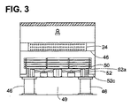
図面の図3は、内部を露出させるためにハウジングの後壁17が取り外されている、図2の線3-3に沿ってとられた図である。図3に見られるように、熱交換機コイル24は、コイルの送込入口26において流入する冷却されるべき液体が、冷却器を流過する、向流空気及び分配システム20からの液体の冷却効果にさらされるための冷却器内で比較的長い進路を有するように、複数回転回するコイル形成管を有する。コイル構造はいずれかの適切な態様で作成することができ、技術上既知のいずれかの適切な態様で筐体12内にブラケットまたは孔あき筐体46によって支持される。
FIG. 3 of the drawing is a view taken along line 3-3 of FIG. 2 with the
図2及び3に見られるように、集水システム30は、以降でさらに詳細に説明されるように、複数の層をなして配列された複数のV字形樋50を有する。これらの樋は、コイル24を通過する液体を中途で捕らえてファン32から遠ざけるために、液体を集める。図3に示されるように、樋50の末端は開放されて、システム30は筐体12のそれぞれの側面においてL字形壁構造52上に支持される。この壁構造は筐体の長さに沿って延び、筐体の側壁が側溝を形成する。2本の側溝は槽34に隣接する開口54に水を運び、集められた水が槽に流入して、上述したように、再循環され得るように、槽の対応する開口に防水シール等によって連結される。
As seen in FIGS. 2 and 3, the
次に図面の図5を参照すれば、集水システム30の一部の拡大斜視図が示される。図6は樋50の1つの独立図である。集水/集液器30の全体は、以降で説明されるように、図7に見られるように相互に連結され、図5に見られるように複数の集水ユニットすなわちセグメント60でつくられる。ユニット60のそれぞれは、樋50を受け入れるために開口64が開けられた、複数の樋支持プレートまたは樋支持構造62を有する。これらの支持プレートは軽量成形プラスチック等で形成することができる。図示される実施形態においては、4枚の支持プレートが備えられるが、支持プレートの数はユニットの大きさに依存するであろう。図5及び6に示される本発明の実施形態において、樋50は一般にV字形であり、樋を支持プレートに嵌め込むに便利なように樋の脚66の撓みを可能にする、可撓性の金属材料またはプラスチック材料で形成される。
Referring now to FIG. 5 of the drawings, an enlarged perspective view of a portion of the
支持プレート62のさらに詳細な図が、樋50のV字形形状に相補的なV字形の底縁形状をプレートの開口64が一般に有することが分かる、図8に示される。開口64のV字形縁端64aは、縁端64aの末端においてプレートにノッチ64cを形成する、突当点64bで終端する。開口64の上端64dは若干のアーチを描く。この構造により、可撓性V字形樋の脚66が相互に若干近づき、よって開口に縦に挿入され得るような、可撓性V字形樋の若干の曲げが可能になる。樋がプレート開口に適切に配置されると、脚66に形成されたノッチ68がプレートのノッチ64cの下の所定の場所に嵌り込むであろう。この構成により、樋を支持プレートに保持するため及びプレート自体を安定にするための、集水システム集水器アセンブリにおける協同手段が提供される。
A more detailed view of the
本システムのスロット/ノッチ構成により、機械的締結具を用いずとも、モジュールの構造一体性を維持する組立てが可能になる。本システムのスロット/ノッチ構成により取外し容易性も提供される。 The slot / notch configuration of the system allows assembly that maintains the structural integrity of the module without the use of mechanical fasteners. The slot / notch configuration of the system also provides ease of removal.
組立てを容易にするだけでなく、この支持プレート構造は、空気が集液器を通って移動している間の空気の一様な横方向分散を保証するため、樋が液体で満たされていても、空気が支持プレートの間を通ることができるように、樋の上方にプレートを通る空気通路を形成する。 In addition to facilitating assembly, this support plate structure ensures the uniform lateral distribution of air as it travels through the collector, so that the soot is filled with liquid. Also forms an air passage through the plate above the ridge so that air can pass between the support plates.
図8及び9を参照すれば、プレート62の側縁70はその上に形成された縦壁素子72を有する。そのような壁素子は、図7に示されるように、複数の集水セグメント60が筐体内に配置される場合、相互に接触するであろう。さらに、図5,7及び8に見られるように、支持プレートの側縁70には部分開口64が形成されており、部分開口64は隣接するプレート上の対応する部分開口に相補的であり、よってプレート側縁が接触したときにそれぞれの部分開口がそれらの間で完全な開口を形成する。この構成により、V字形樋素子50がそのような開口に嵌め込まれると、樋自体が2枚の支持プレートの間の連結体となり、集水セグメント60を相互連結させるためにはたらく。図示される実施形態にはプレート62のそれぞれの側縁に2つのそのような部分開口が示されているが、そのような開口の数はプレートの大きさに依存するであろう。
Referring to FIGS. 8 and 9, the side edge 70 of the
図9に見られるように、支持プレート62の底縁74は、支持プレート62から延び出し、側溝壁52a(図3)の上端に支持のために載ることができる支持面78を底縁74に与える、薄い、オフセットされた壁体75を有する。さらに、1つより多くの集水ユニット層が用いられる場合、ユニットは、プレート62の上端79上に支持面78を載せて、相互に積み重ねることができる。
As seen in FIG. 9, the
上述したように、本発明の好ましい実施形態は集められた液体を側溝に導く集液チャネルを設けるためにV字形樋を用いるが、U字形樋のような別の適切な形状も用い得ることは当然である。さらに、図3に示されるように、樋の逆側の末端は水を一対の側溝に流し込むために開放されており、望ましければ、筐体内の単一の側溝に全ての液体が流し込まれるように、樋の一端を閉じることができる。 As mentioned above, although the preferred embodiment of the present invention uses a V-shaped scissors to provide a collection channel that guides the collected liquid to the gutter, it is possible that other suitable shapes such as U-shaped scissors can also be used. Of course. Further, as shown in FIG. 3, the opposite end of the jar is open to allow water to flow into the pair of side grooves, so that all liquid can be poured into a single side groove in the housing if desired. In addition, one end of the bag can be closed.
次に図11を参照すれば、集水器の樋アレイの略図が与えられる。図11に見られるように、ファンから流れてくる空気は低層側の樋50に当たり、樋間の間隙を通過して、上方の樋の底に向かって拡散する。さらに、開口64は樋の上方に大きな上部領域をもって形成されるから、図11の右上に簡略に描かれ、矢印Bで示されるように、樋が水で満たされていたとしても、空気はプレート62を通ってプレートの逆側に流れることができる。この拡散パターンは、集水システムの上部において空気が完全に横方向に拡散して、冷却コイルを通る一様な流れになり、したがって熱伝達が一様になるように、樋の複数の層でおこり、複数の層にわたって継続する。同じく図11に見られるように、それぞれの層の樋50は、相互に横方向で隔てられ、上下の層の樋に対してオフセットされている。それぞれの層における樋の末端の間隔78は樋自体の幅より小さく、したがって、ミストまたは液滴として集液器を通ってファンに向けて流れ落ちる液体を樋が集める機会が増える。
Referring now to FIG. 11, a schematic representation of a water collecting ridge array is provided. As seen in FIG. 11, the air flowing from the fan hits the
好ましい実施形態の1つにおいて、単一の樋50の脚の幅は約3インチ(76.2mm)であり、隣り合う脚の末端の間隔は2インチ(50.8mm)である。
In one preferred embodiment, the leg width of a
図2〜9に示されるように5層の樋を用いると、熱交換機を通って槽34に戻る水滴の実質的に100%が集められることが分かった。しかし、望ましければさらに多いかまたは少ない層を用いることができる。 It has been found that using five layers of soot as shown in FIGS. 2-9, substantially 100% of the water droplets returning through the heat exchanger back to the tub 34 are collected. However, more or fewer layers can be used if desired.
もちろん、上述した樋の一様間隔が必須でないことは当然である。実際、用途または筐体の特定の形状に依存して気流を特定の領域に導くために樋の間隔を変えることは本発明の範囲内にある。さらに、隣り合う樋の間の開口の大きさを変えることは樋間の空気速度に影響するであろう。樋間の間隙を変えることにより、システム全体にわたって空気分布の均衡を一層良くとることができる。しかし、上述した通り、水がファンから逃れることができないように樋が重なり合ったままでいることが重要である。 Of course, the above-mentioned uniform spacing of the ridges is not essential. In fact, it is within the scope of the present invention to vary the spacing of the ridges to direct the airflow to a specific area, depending on the application or the specific shape of the housing. Furthermore, changing the size of the opening between adjacent ridges will affect the air velocity between the ridges. By changing the gap between the ridges, the air distribution can be better balanced throughout the system. However, as mentioned above, it is important that the folds remain overlapped so that water cannot escape from the fan.
図10は、先に説明した支持プレート構造と同様であるが4層の集液樋を用いる、支持プレート構造を示す。この場合、支持プレート62'は、プレートの縁端が相互にかみ合い、縁端上の縦壁72が相互支持のために重なり合うように、若干異なる縁端形状を有する。これらの縦壁には、隣接するプレートの対向する平縁端72'を受け入れ、縁端72'と機能的に嵌合して、隣接プレートと嵌り合うようであろう、嵌込みU字形状のような、スナップ嵌め構造を形成することができる。
FIG. 10 shows a support plate structure that is similar to the support plate structure described above, but uses a four-layered collection tank. In this case, the support plate 62 'has a slightly different edge shape so that the edges of the plates engage each other and the
図12及び13は本発明の別の実施形態を簡略に示す。この場合、先の実施形態におけるように個別の樋50を用いるのではなく、それぞれ樋の頂点の間を垂直に延びる複合ウエブ82によって連結された、樋対80が備えられる。そのような構造体は、先に説明した開口64に対応する、支持プレートの開口に嵌め込まれることになろう。しかし、この実施形態のプレートは、ウエブ82を収めるため、開口64の間を延びるスロット83を有するであろう。図12において、プレート及びプレートの開口は簡略に示されている。ウエブ82連結されて対になった樋を備えることにより、構造体に若干高い剛性が与えられるが、支持プレートを通る空気の分布は維持される。
Figures 12 and 13 schematically illustrate another embodiment of the present invention. In this case, instead of using
図8を再び参照すれば、樋支持プレートには、下方に延び、樋からでて下側の樋に向かうリブ90が形成されている。本発明にしたがう冷却器の動作の過程において、システム20からの液体はプレートの表面上に凝縮し、液膜になって支持プレートに沿って下方に流れ得ることが分かった。そのような凝縮はファン領域に入らないように集められることが必要である。したがって、リブ90が、凝縮液膜が下方に流れる間に凝縮液膜を細分して直下の集水樋に導く。同様に、凝縮液膜は塔の内部壁面上にも形成され得る。したがって、図2に示されるように、内部壁面上を下方に流れている凝縮液膜を樋に導くための偏流プレート96が端壁17上に備えられる。側壁上では凝縮液膜は下方に流れて側溝に導かれるであろうから、図3に見られるように、そのような偏流プレートは必要ではない。
Referring to FIG. 8 again, the rib support plate is formed with
次に図4を参照すれば、本発明の技術が蒸発冷却器に同様に用いるために適合されている。蒸発冷却器において、液体はコイル24を通過する代わりに筐体12内の層100を形成する周知の構造の蒸発冷却材を通過する対向流になる。蒸発冷却材は多くの形態をとることができ、一般には、液体と空気が対向して通過する空気通路を形成する、成形コルゲートプラスチックシートとすることができるであろう。水分は空気と接触しながら冷却材内で蒸発し、よって空調システム等に用いるための空気を冷却する。
Referring now to FIG. 4, the technique of the present invention is adapted for use in an evaporative cooler as well. In the evaporative cooler, instead of passing through the
上述したように、集水システムは底部ファンシステムを備える小型可搬液体冷却器または冷却塔に関して図示及び説明されるが、集水システムは、その優れた空気拡散及び分散特性及び利点を保持したまま、例えば特許文献1及び3またはその他のシステムを備える、液体冷却器または充填材料の下に従来の集水槽または水溜めを有するさらに通常のシステムに用いることができる。 As mentioned above, although the water collection system is illustrated and described with respect to a small portable liquid cooler or cooling tower with a bottom fan system, the water collection system retains its superior air diffusion and dispersion characteristics and advantages. Can be used in a more conventional system having a conventional catchment tank or sump under a liquid cooler or filling material, including, for example, US Pat.
次に図14及び15を参照すれば、下層集水器の樋50間の間隙を閉じて、水分配システムから集水器を通って滴下しているいかなる液体も集水器の下のファンに入れないようにするための、ダンパーシステムが示されている。図14及び15に示される実施形態においては、下層の樋50間の間隙のそれぞれに小形の樋様ダンパー110が備えられる。ダンパー110は樋20の長さに対応する長さを有し、一般に、それぞれの樋の脚の上端に載る小さな脚をもつ、概ねM字形状を有する。これらのダンパーは軽量プラスチック部材であり、ファンが動作しているときは空気圧の影響の下に図15に示される位置まで上方に移動して、上方の樋の底面に保持されるであろう。ファンが停止すると、これらのダンパーは下のレベルの樋の上端に降下して、その上に載るであろう。これらのダンパーは自由に浮揚できるが、好ましければ、図14に示される閉位置から図15に示される開位置までのダンパーの垂直方向移動を誘導するための、支持プレートに形成されたスロットに嵌合する誘導ピンをダンパーに形成することができるであろう。
Referring now to FIGS. 14 and 15, any liquid dripping from the water distribution system through the collector is closed to the fan below the collector, with the gap between the
図16a及び16bに示されるような、別の構成において、一体蝶番112または当業者が思いつくであろう、その他の適切な軸旋回機構を用いて、ダンパー110を樋と一体形成することができる。この場合、ダンパーは、最下層の樋の隣のV字形樋の頂点に連結された一対の細長いプレート111で形成される。それぞれのプレート111は、樋の内の2つに示されるような一体蝶番112によるか、あるいはロッド上でのダンパープレート111の軸旋回を可能にする半円柱蝶番115が嵌合する、V字の頂点に形成された旋回軸ロッドを有する適切な機械的蝶番により、樋に連結される。これらの構成のいずれかにより、ファンが停止しているときに、ダンパーは図16aに実線で示される位置に重力によって下がり、ファンが作動しているときにダンパーは強制気流の影響の下で図16bの点線の位置まで移動するであろう。当業者には当然であろうように、樋が支持プレートに載ることができるように、ダンパーは上述したノッチ68の間のセグメントにおいて樋上に形成される。さらに、樋が支持プレートに装着されている間は装着を妨害しないように、軸旋回ダンパーパネルは図16bの開位置に保持しておくことができる。さらに、上述した本発明の集液システムによって提供される改善された空気分散を図15または図16のダンパーが妨げることはないであろう。
In another configuration, as shown in FIGS. 16a and 16b, the
本発明におけるダンパーの使用は、液体をファンから隔離して、ファンを害し、損傷を生じさせ得るであろう、腐蝕を回避するためだけではなく、水を冷凍状態にしないでおくためにも有益である。 The use of dampers in the present invention is beneficial not only to avoid corrosion, but also to keep the water refrigerated, which could isolate the liquid from the fan and harm the fan and cause damage. It is.
いくつかの用途において、(ファンが作動しているか停止しているかにかわらず)水分が樋の外表面上に凝縮し得るかまたは樋に縁端に打ち当たる液滴が表面張力または何か別の機構によって樋の外表面に流れ得ると考えられる。そのような液体は外表面に沿って流れて、下の樋に落ち込むであろう。液滴が最下層の樋で生じた場合、液滴はファン上に落下し得るはずである。 In some applications, water can condense on the outer surface of the heel (whether the fan is running or stopped), or droplets that hit the edge of the heel are subject to surface tension or something else. It is thought that it can flow to the outer surface of the ridge by this mechanism. Such liquid will flow along the outer surface and fall into the lower ridge. If a drop occurs on the bottom ridge, it should be able to fall on the fan.
このファン上への液滴落下の可能性を排除するため、図20〜22に示される集液システムを用いることができる。この実施形態においては、上述したような開口64が支持プレート62に形成される。さらに、これらの開口には、開口縁端64aの合流点において垂直スロット64eが形成される。それぞれのスロット64eの下端に小V字形スロット64fも形成される。
In order to eliminate the possibility of the droplet falling onto the fan, the liquid collection system shown in FIGS. 20 to 22 can be used. In this embodiment, the
スロット64e及び64fは、垂直脚67a及びその末端に形成された小V字形樋67bを有する樋エクステンション67を受け入れて収めるように形成される。そのような樋に外表面上に凝縮するかまたは移動する液体は小樋67bに取り込まれる。もちろん、樋67bの長さが本質的に、その中に集められた液体を塔の側溝に運ぶために、樋66の長さと同じであることは当然である。
The slots 64e and 64f are formed to receive and accommodate a
エクステンション67を有する樋66は、図22示されるように、開口64及びスロット64e及び64fに受け入れられる。図22にはプレート62の一部しか示されておらず、明解さのために1つの樋66が所定の位置に示されている。本システムを組み立てるため、上述したように支持プレート62の開口64内に樋が誘導されると同時に、ノッチ68が支持プレートと所定の位置に合わせられて嵌め込まれるまで、樋エクステンションがスロット64e及び64f内に誘導される。
As shown in FIG. 22, the
原理的には、上述したように上方の樋の外表面上のいかなる液体もその下の樋に捕らえられて側溝に運ばれるはずであるから、そのようなエクステンション67は支持プレートの最下層の樋にしか必要ではないはずである。したがって、上述したように、下層の樋の外表面上のいかなる残留液体も小樋67bによって集められて、同様に側溝に送られる。しかし、そのような液体を可能な限り迅速に気流から除去するため、集液システムの全ての樋層がエクステンション67を有する樋を備えることが好ましい。
In principle, as described above, any liquid on the outer surface of the upper ridge should be trapped in the lower ridge and carried into the gutter, so such an
図17〜19は集水槽34をさらに詳細に示す。直接強制通風液体冷却器または閉ループ冷却塔に用いる代表的な用途においては、上述したように、従来技術の装置に比較してこの槽は小形につくられる。これは、そのようなシステムでは水が流体冷却器を決して離れず、槽からスプレーヘッドに送られ、再び戻る、再循環を行うからである。これが、水が冷却のためにシステムの外部で用いられてから戻される冷却塔との違いである。 17-19 show the water collection tank 34 in more detail. In typical applications used for direct forced liquid coolers or closed loop cooling towers, as described above, the vessel is made smaller compared to prior art devices. This is because in such a system, the water never leaves the fluid cooler and is sent from the tank to the spray head and recirculates again. This is the difference from a cooling tower where water is used outside the system for cooling and then returned.
液体冷却器とともに用いるための本発明の集水槽は一般に、システム全体に対してほぼ90ガロン(約340リットル)の液体を保持するであろう。上で論じられるように、また図17〜19に示されるように、槽は、全ての液体が底の流出口に導かれるように、テーパ付きの概ね三角形の4枚の壁で形成されるか、または円錐形としてつくられた、テーパ付きの底35を有する。この構成により、作動液内に集められた沈殿物等は槽内のテーパ付き底に溜め込まれ、この沈殿物は必要に応じてドレーン120を通してシステムから容易に流し出すことができる。さらに、槽は筐体外部に配置され、簡単に取り外すことができる上蓋14を有するから、清掃のための槽へのアクセスが容易である。さらにまた、層はポンプより高い位置に置かれるから、作動に必要な水頭は従来システムより低く、また流出口39の位置により、ポンプは迎え水が入れられたままであり、よって動作に必要なポンプが小型になる。
The catchment tank of the present invention for use with a liquid cooler will generally hold approximately 90 gallons of liquid for the entire system. As discussed above, and as shown in FIGS. 17-19, is the tank formed of four tapered, generally triangular walls so that all liquid is directed to the bottom outlet? Or having a tapered bottom 35 made as a cone. With this configuration, the sediment collected in the working fluid is stored in a tapered bottom in the tank, and this sediment can be easily discharged from the system through the drain 120 as necessary. Furthermore, since the tank is disposed outside the housing and has an
上述したように、本発明のシステムは多くの大きな改善を提供する。集液システムは、下降してくる水の全てを集め、また全充填材が熱交換器または充填材の全表面にかけて実質的に等しい気流を得るように上昇気流を導き、分散させる。これにより、水への空気の混合の効率を一層高め、よってシステムの性能を高める。さらに、集水器の構造により、既存の技術に比較して、集水器パネルにかけてかなりの圧力降下が得られる。低減された圧力降下も冷却塔の熱性能を高める。さらに、集水システムは製造が比較的簡単で、経済的である。 As mentioned above, the system of the present invention provides many significant improvements. The collection system collects all of the descending water and directs and disperses the updraft so that the total filler obtains a substantially equal airflow over the entire surface of the heat exchanger or filler. This further increases the efficiency of mixing the air with the water and thus increases the performance of the system. Furthermore, the structure of the water collector provides a significant pressure drop across the water collector panel compared to existing technology. The reduced pressure drop also increases the thermal performance of the cooling tower. Furthermore, the water collection system is relatively simple to manufacture and economical.
本明細書において図面に示される特定の実施形態を参照して本発明を説明したが、本発明がそのような正確な実施形態に限定されず、本発明の範囲及び精神を逸脱することなく様々な変更及び改変が本発明に実施され得ることは当然である。 Although the invention herein has been described with reference to particular embodiments shown in the drawings, the invention is not limited to such precise embodiments and can be varied without departing from the scope and spirit of the invention. Of course, various changes and modifications may be made to the invention.
10 液体冷却器
12 筐体
14 オープントップ
15 側壁
16 底壁
17 端壁
20 液体分配システム
22 筐体上端
24 熱交換機
26 送込端
28 排出端
30 集水器
32 ファン
34 集水槽
36 放出管
38 ポンプ
40 分配管
42 ノズル
44 ドリフト除去構造
46 Iビーム脚
48 孔あき筐体
49 構造下空間
50 V字形樋
52 L字形構造
54 開口
62 支持プレート
96 偏向プレート
DESCRIPTION OF
Claims (16)
筐体、
前記液体冷却装置の外部で用いるために冷却されるべき第1の液体を収めるための前記筐体内の熱交換機手段、
前記熱交換機手段上に第2の液体を、前記第2の液体が重力により前記熱交換機手段を通って下降するように、分配するための、前記熱交換機手段の上方に配置された液体分配手段、
前記第2の液体の蒸発冷却をおこさせ、よって前記熱交換機手段内の前記第1の液体を冷却するために、前記熱交換機手段を通して空気を吹き上げるための、前記熱交換機手段の下方に配置されたファン手段、
前記熱交換機手段から落ちてくる前記第2の液体の実質的に全てを集めるための集水樋の複数の層を有する、前記熱交換機手段の下方で前記筐体内の集水手段であって、前記層のそれぞれの前記樋は前記それぞれの層の上方または下方の前記層の前記樋から横方向にオフセットされており、前記樋のそれぞれは少なくとも1つの開放端を有するものである集水手段、
前記樋の前記少なくとも1つの開放端から前記第2の液体を受け取るための前記筐体内の側溝手段、及び
前記樋の下部層の内の少なくとも1つに付帯する、少なくとも1つのファンが停止しているときは前記層の前記少なくとも1つにおいて隣り合う樋間の間隙を閉じ、前記ファンが作動しているときは前記少なくとも1つのファンによって生じる気流に応答して前記間隙を開くための、手段、
を備えることを特徴とする装置。 In the direct forced draft liquid cooling device,
Housing,
Heat exchanger means in the housing for containing a first liquid to be cooled for use outside the liquid cooling device;
Liquid distribution means disposed above the heat exchanger means for distributing the second liquid on the heat exchanger means such that the second liquid descends through the heat exchanger means by gravity. ,
Arranged below the heat exchanger means for blowing up air through the heat exchanger means to evaporate and cool the second liquid and thus cool the first liquid in the heat exchanger means. Fan means,
Water collecting means in the housing below the heat exchanger means, having a plurality of layers of water collecting tanks for collecting substantially all of the second liquid falling from the heat exchanger means, Water collecting means , wherein each said ridge of said layer is laterally offset from said ridge of said layer above or below said respective layer, each said ridge having at least one open end ;
A gutter means in the housing for receiving the second liquid from the at least one open end of the trough; and
When at least one fan attached to at least one of the lower layers of the ridge is stopped, the gap between adjacent ridges is closed in the at least one of the layers, and the fan is operating. Means for opening the gap in response to the air flow generated by the at least one fan,
A device comprising:
筐体、
前記液体冷却装置の外部で用いるために冷却されるべき第1の液体を収めるための前記筐体内の熱交換機手段、
前記熱交換機手段上に第2の液体を、前記第2の液体が重力により前記熱交換機手段を通って下降するように、分配するための、前記熱交換機手段の上方に配置された液体分配手段、
前記第2の液体の蒸発冷却をおこさせ、よって前記熱交換機手段内の前記第1の液体を冷却するために、前記熱交換機手段を通して空気を吹き上げるための、前記熱交換機手段の下方に配置されたファン手段、
前記熱交換機手段から落ちてくる前記第2の液体の実質的に全てを集めるための集水樋の複数の層を有する、前記熱交換機手段の下方で前記筐体内の集水手段であって、前記層のそれぞれの前記樋は前記それぞれの層の上方または下方の前記層の前記樋から横方向にオフセットされており、前記樋のそれぞれは少なくとも1つの開放端を有するものである集水手段、及び
前記樋の前記少なくとも1つの開放端から前記第2の液体を受け取るための前記筐体内の側溝手段、
を備え、
前記集水手段が前記樋を受け入れるための開口を有する少なくとも一対の樋支持プレート構造体を備え、前記プレート構造体が前記樋の長さに沿って軸方向に相互に隔てられ、
前記支持プレート構造体が、前記プレート構造体上の前記第2の液体のいずれをも下側の前記樋層に導くために配置された、前記プレート構造体の前記開口に隣接する表面リブ手段を備えることを特徴とする装置。 In the direct forced draft liquid cooling device,
Housing,
Heat exchanger means in the housing for containing a first liquid to be cooled for use outside the liquid cooling device;
Liquid distribution means disposed above the heat exchanger means for distributing the second liquid on the heat exchanger means such that the second liquid descends through the heat exchanger means by gravity. ,
Arranged below the heat exchanger means for blowing up air through the heat exchanger means to evaporate and cool the second liquid and thus cool the first liquid in the heat exchanger means. Fan means,
Water collecting means in the housing below the heat exchanger means, having a plurality of layers of water collecting tanks for collecting substantially all of the second liquid falling from the heat exchanger means, Water collecting means, wherein each said ridge of said layer is laterally offset from said ridge of said layer above or below said respective layer, each said ridge having at least one open end; And a gutter means in the housing for receiving the second liquid from the at least one open end of the trough;
Equipped with a,
The water collecting means comprises at least a pair of eaves support plate structures having openings for receiving the eaves, the plate structures being axially spaced along the length of the eaves;
Surface rib means adjacent to the opening of the plate structure, wherein the support plate structure is arranged to guide any of the second liquid on the plate structure to the undercoat layer. device, characterized in that it comprises.
筐体、
前記液体冷却装置の外部で用いるために冷却されるべき第1の液体を収めるための前記筐体内の熱交換機手段、
前記熱交換機手段上に第2の液体を、前記第2の液体が重力により前記熱交換機手段を通って下降するように、分配するための、前記熱交換機手段の上方に配置された液体分配手段、
前記第2の液体の蒸発冷却をおこさせ、よって前記熱交換機手段内の前記第1の液体を冷却するために、前記熱交換機手段を通して空気を吹き上げるための、前記熱交換機手段の下方に配置されたファン手段、
前記熱交換機手段から落ちてくる前記第2の液体の実質的に全てを集めるための集水樋の複数の層を有する、前記熱交換機手段の下方で前記筐体内の集水手段であって、前記層のそれぞれの前記樋は前記それぞれの層の上方または下方の前記層の前記樋から横方向にオフセットされており、前記樋のそれぞれは少なくとも1つの開放端を有するものである集水手段、及び
前記樋の前記少なくとも1つの開放端から前記第2の液体を受け取るための前記筐体内の側溝手段、
を備え、
前記集水手段が前記樋を受け入れるための開口を有する少なくとも一対の樋支持プレート構造体を備え、前記プレート構造体が前記樋の長さに沿って軸方向に相互に隔てられ、
前記支持プレート構造体のそれぞれが、対向する末端が相互に突き当たるように適合されている実質的に同等の形状の少なくとも2枚のプレート素子及び前記末端を確実に突き合わせておくための手段を有することを特徴とする装置。 In the direct forced draft liquid cooling device,
Housing,
Heat exchanger means in the housing for containing a first liquid to be cooled for use outside the liquid cooling device;
Liquid distribution means disposed above the heat exchanger means for distributing the second liquid on the heat exchanger means such that the second liquid descends through the heat exchanger means by gravity. ,
Arranged below the heat exchanger means for blowing up air through the heat exchanger means to evaporate and cool the second liquid and thus cool the first liquid in the heat exchanger means. Fan means,
Water collecting means in the housing below the heat exchanger means, having a plurality of layers of water collecting tanks for collecting substantially all of the second liquid falling from the heat exchanger means, Water collecting means, wherein each said ridge of said layer is laterally offset from said ridge of said layer above or below said respective layer, each said ridge having at least one open end; And a gutter means in the housing for receiving the second liquid from the at least one open end of the trough;
Equipped with a,
The water collecting means comprises at least a pair of eaves support plate structures having openings for receiving the eaves, the plate structures being axially spaced along the length of the eaves;
Each of the support plate structures has at least two plate elements of substantially equivalent shape adapted to abut opposite ends and a means for ensuring that the ends meet. A device characterized by.
筐体、
前記液体冷却装置の外部で用いるために冷却されるべき第1の液体を収めるための前記筐体内の熱交換機手段、
前記熱交換機手段上に第2の液体を、前記第2の液体が重力により前記熱交換機手段を通って下降するように、分配するための、前記熱交換機手段の上方に配置された液体分配手段、
前記第2の液体の蒸発冷却をおこさせ、よって前記熱交換機手段内の前記第1の液体を冷却するために、前記熱交換機手段を通して空気を吹き上げるための、前記熱交換機手段の下方に配置されたファン手段、
前記熱交換機手段から落ちてくる前記第2の液体の実質的に全てを集めるための集水樋の複数の層を有する、前記熱交換機手段の下方で前記筐体内の集水手段であって、前記層のそれぞれの前記樋は前記それぞれの層の上方または下方の前記層の前記樋から横方向にオフセットされており、前記樋のそれぞれは少なくとも1つの開放端を有するものである集水手段、及び
前記樋の前記少なくとも1つの開放端から前記第2の液体を受け取るための前記筐体内の側溝手段、
を備え、
前記集水手段が前記樋を受け入れるための開口を有する少なくとも一対の樋支持プレート構造体を備え、前記プレート構造体が前記樋の長さに沿って軸方向に相互に隔てられ、
前記支持構造体プレート構造体のそれぞれが、対向する末端が相互に突き当たるように適合されている少なくとも2枚のプレート素子を有し、前記対向する末端が突き当たっているときに、合わせて樋に対する開口を形成する切欠き部分が前記対向する末端のそれぞれに形成されており、前記樋及び前記プレート構造体の前記協同手段が樋をそれぞれに、及び前記突き当たっているプレート素子を一緒に、確実に固定することを特徴とする装置。 In the direct forced draft liquid cooling device,
Housing,
Heat exchanger means in the housing for containing a first liquid to be cooled for use outside the liquid cooling device;
Liquid distribution means disposed above the heat exchanger means for distributing the second liquid on the heat exchanger means such that the second liquid descends through the heat exchanger means by gravity. ,
Arranged below the heat exchanger means for blowing up air through the heat exchanger means to evaporate and cool the second liquid and thus cool the first liquid in the heat exchanger means. Fan means,
Water collecting means in the housing below the heat exchanger means, having a plurality of layers of water collecting tanks for collecting substantially all of the second liquid falling from the heat exchanger means, Water collecting means, wherein each said ridge of said layer is laterally offset from said ridge of said layer above or below said respective layer, each said ridge having at least one open end; And a gutter means in the housing for receiving the second liquid from the at least one open end of the trough;
Equipped with a,
The water collecting means comprises at least a pair of eaves support plate structures having openings for receiving the eaves, the plate structures being axially spaced along the length of the eaves;
Each of the support structure plate structures has at least two plate elements that are adapted to abut the opposite ends against each other, and when the opposite ends abut, together the opening to the heel Are formed at each of the opposing ends, and the cooperating means of the ridge and the plate structure securely fix the ridge to each other and the abutting plate element together. A device characterized by that.
Applications Claiming Priority (7)
| Application Number | Priority Date | Filing Date | Title |
|---|---|---|---|
| US20899509P | 2009-03-03 | 2009-03-03 | |
| US61/208,995 | 2009-03-03 | ||
| US21782209P | 2009-06-05 | 2009-06-05 | |
| US61/217,822 | 2009-06-05 | ||
| US27072309P | 2009-07-13 | 2009-07-13 | |
| US61/270,723 | 2009-07-13 | ||
| PCT/US2010/024929 WO2010110980A1 (en) | 2009-03-03 | 2010-02-22 | Direct forced draft fluid cooler/cooling tower and liquid collector therefor |
Publications (3)
| Publication Number | Publication Date |
|---|---|
| JP2012519824A JP2012519824A (en) | 2012-08-30 |
| JP2012519824A5 JP2012519824A5 (en) | 2013-04-11 |
| JP5633938B2 true JP5633938B2 (en) | 2014-12-03 |
Family
ID=42781363
Family Applications (1)
| Application Number | Title | Priority Date | Filing Date |
|---|---|---|---|
| JP2011552972A Expired - Fee Related JP5633938B2 (en) | 2009-03-03 | 2010-02-22 | Direct forced draft cooler / cooling tower and liquid collector therefor |
Country Status (9)
| Country | Link |
|---|---|
| US (3) | US9033318B2 (en) |
| EP (1) | EP2404115A4 (en) |
| JP (1) | JP5633938B2 (en) |
| KR (1) | KR20120000051A (en) |
| CN (1) | CN102341655B (en) |
| BR (1) | BRPI1006288A2 (en) |
| CA (1) | CA2752644A1 (en) |
| MX (1) | MX2011009109A (en) |
| WO (1) | WO2010110980A1 (en) |
Families Citing this family (30)
| Publication number | Priority date | Publication date | Assignee | Title |
|---|---|---|---|---|
| CN102341655B (en) * | 2009-03-03 | 2014-02-26 | 蒙特斯公司 | Direct forced draft fluid cooler/cooling tower and liquid collector therefor |
| US20150330710A1 (en) * | 2009-03-03 | 2015-11-19 | Harold D. Curtis Revocable Trust | Direct Forced Draft Fluid Cooling Tower |
| US9617087B2 (en) | 2010-10-28 | 2017-04-11 | General Electric Technology Gmbh | Control valve and control valve system for controlling solids flow, methods of manufacture thereof and articles comprising the same |
| US9557115B2 (en) * | 2010-10-28 | 2017-01-31 | General Electric Technology Gmbh | Orifice plate for controlling solids flow, methods of use thereof and articles comprising the same |
| CN102141274B (en) * | 2011-03-24 | 2014-03-26 | Tcl空调器(中山)有限公司 | Split air-conditioner |
| US20130277020A1 (en) * | 2012-04-23 | 2013-10-24 | Aaf-Mcquay Inc. | Heat exchanger |
| CN103458652B (en) * | 2012-05-31 | 2016-06-01 | 英业达股份有限公司 | Electronic installation |
| CN102778144A (en) * | 2012-08-16 | 2012-11-14 | 上海廷亚冷却系统有限公司 | Jet type evaporation cooler with low water outlet temperature |
| US9057564B2 (en) * | 2012-12-17 | 2015-06-16 | Baltimore Aircoil Company, Inc. | Cooling tower with indirect heat exchanger |
| EP3117175B1 (en) | 2014-03-13 | 2018-11-14 | Schneider Electric IT Corporation | Water collection system for indirect evaporative cooler |
| US20150276318A1 (en) * | 2014-03-28 | 2015-10-01 | Ronald J. Marks | Cmu cooling tower and method of construction |
| US10107001B2 (en) | 2014-03-28 | 2018-10-23 | Syntech Towers, L.L.C. | CMU cooling tower and method of construction |
| EP3158271B1 (en) | 2014-06-20 | 2021-09-22 | Nortek Air Solutions Canada, Inc. | Systems and methods for managing conditions in enclosed space |
| WO2016054444A1 (en) * | 2014-10-01 | 2016-04-07 | E-Polytech Mfg. Sys, Llc | Compact heat exchange system and method of cooling |
| CA2986055A1 (en) | 2015-05-15 | 2016-11-24 | Nortek Air Solutions Canada, Inc. | Using liquid to air membrane energy exchanger for liquid cooling |
| WO2017117644A1 (en) | 2016-01-08 | 2017-07-13 | Moghaddam Davood Ghadiri | Integrated make-up air system in 100% air recirculation system |
| US10775117B2 (en) | 2016-09-30 | 2020-09-15 | Baltimore Aircoil Company | Water collection/deflection arrangements |
| US10852079B2 (en) | 2017-07-24 | 2020-12-01 | Harold D. Curtis | Apparatus for cooling liquid and collection assembly therefor |
| US10677543B2 (en) * | 2017-08-31 | 2020-06-09 | Baltimore Aircoil Company, Inc. | Cooling tower |
| US10527303B2 (en) | 2017-11-16 | 2020-01-07 | Grahame Ernest Maisey | Load follower and load anticipator for a liquid desiccant air conditioning system |
| CN113167538A (en) * | 2018-10-17 | 2021-07-23 | Js创造私人有限公司 | Cooling device and method for cooling a water flow |
| WO2020161611A1 (en) * | 2019-02-05 | 2020-08-13 | Khalifa University of Science and Technology | Water droplets collection device from airflow using electrostatic separators |
| WO2020251424A1 (en) * | 2019-06-13 | 2020-12-17 | Ibrahim Hussein Mohamed Hussein | Highly-efficient horizontal thermal exchange air condition |
| US20210172619A1 (en) | 2019-12-10 | 2021-06-10 | Lg Electronics Inc. | Air management apparatus or device |
| CN112944471A (en) * | 2019-12-10 | 2021-06-11 | Lg电子株式会社 | Air management device |
| US11609051B2 (en) | 2020-04-13 | 2023-03-21 | Harold D. Revocable Trust | Apparatus for cooling liquid and collection assembly therefor |
| CN114623499B (en) * | 2020-12-11 | 2023-07-21 | 广东美的白色家电技术创新中心有限公司 | Air conditioner indoor unit and air conditioner |
| CN113251527B (en) * | 2021-06-09 | 2022-06-10 | 福建蓝海节能科技有限公司 | Water distributor and water cold accumulation system |
| CN114234169B (en) * | 2021-12-25 | 2023-08-25 | 东营威联化学有限公司 | Sieve plate tray type regular sewage draining expansion vessel |
| CN114264183B (en) * | 2021-12-30 | 2023-09-22 | 东营联合石化有限责任公司 | Oil gas cooler |
Family Cites Families (55)
| Publication number | Priority date | Publication date | Assignee | Title |
|---|---|---|---|---|
| US1647281A (en) | 1926-04-01 | 1927-11-01 | Frank M Doyle | Cooling tower |
| US1803854A (en) | 1926-10-14 | 1931-05-05 | Atmospheric Nitrogen Corp | Method of separating finely divided liquids from gases and apparatus therefor |
| FR702279A (en) | 1929-12-10 | 1931-04-03 | gas and smoke purifier | |
| US3217631A (en) | 1963-07-16 | 1965-11-16 | Formica Corp | Louver |
| CH431600A (en) | 1965-07-09 | 1967-03-15 | Lex Eduard | Ventilation grilles for vehicles, in particular rail vehicles |
| US3290025A (en) | 1965-11-19 | 1966-12-06 | Baltimore Aircoil Co Inc | Trough system for evaporative heat exchangers |
| US3384165A (en) * | 1966-02-03 | 1968-05-21 | Du Pont | Heat exchanger |
| US3647191A (en) | 1970-07-27 | 1972-03-07 | Marley Co | Splash bar for cooling tower fill assembly |
| US3803997A (en) | 1972-01-21 | 1974-04-16 | Mahon Ind Corp | Particle collecting device |
| US3750418A (en) | 1972-03-20 | 1973-08-07 | Borg Warner | Evaporator and condensate collector arrangement for refrigeration apparatus |
| JPS4911345U (en) * | 1972-04-27 | 1974-01-30 | ||
| US3834129A (en) | 1972-09-13 | 1974-09-10 | E Darlinger | Absorption optimization apparatus |
| JPS5219245Y2 (en) * | 1973-05-28 | 1977-05-02 | ||
| US3968738A (en) | 1974-04-29 | 1976-07-13 | Champion International Corporation | Plastic louver frame assembly |
| JPS51125666A (en) | 1975-04-25 | 1976-11-02 | Mitsubishi Heavy Ind Ltd | A gas-liquid contact arrangement |
| JPS5219245A (en) | 1975-08-06 | 1977-02-14 | Nitto Electric Ind Co | Method of producing resisting elements or resisting network |
| US4014669A (en) * | 1975-12-24 | 1977-03-29 | Ecodyne Corporation | Self-locking drift eliminator |
| DE2606429C3 (en) | 1976-02-18 | 1979-05-31 | Krapf & Lex, 8480 Weiden | Ventilation grille with rows of slats |
| DE7717599U1 (en) | 1977-06-03 | 1977-11-17 | Regehr, Ulrich, Dr.-Ing., 5100 Aachen | LAMINATED DEFLECTOR FOR SEPARATING LIQUID CARRIED OUT IN A LIQUID-STEAM MIXTURE |
| US4164399A (en) | 1977-09-28 | 1979-08-14 | American Air Filter Company, Inc. | Wet scrubbing device |
| US4196157A (en) * | 1978-07-06 | 1980-04-01 | Baltimore Aircoil Company, Inc. | Evaporative counterflow heat exchange |
| US4273733A (en) * | 1979-07-30 | 1981-06-16 | Niagara Blower Company | Apparatus for cooling fluids |
| FR2493718A1 (en) * | 1980-11-12 | 1982-05-14 | Hamon | DEVICE FOR COLLECTING A FLOWING FALLING FLUID AND ITS APPLICATION TO AN INSTALLATION FOR CONTRA-CURRENT CONTACTING A LIQUID WITH A GAS |
| US4500330A (en) * | 1983-05-31 | 1985-02-19 | Evapco, Inc. | Drift eliminator |
| US4521350A (en) | 1984-01-16 | 1985-06-04 | The Munters Corporation | Drainage collection system |
| US4759315A (en) | 1986-09-02 | 1988-07-26 | Crane Co. | Deaerator tray for a steam boiler feedwater heater system |
| US5161248A (en) | 1989-10-02 | 1992-11-03 | Motorola, Inc. | Method of predicting cell-to-cell hand-offs for a satellite cellular communications system |
| US5000883A (en) | 1989-10-23 | 1991-03-19 | Max Leva | Apparatus and method for supporting packing in mass transfer towers and subsequent liquid redistribution |
| US4981113A (en) | 1990-05-04 | 1991-01-01 | Crane, Co. | Deaerator tray for a steam boiler feedwater heater system |
| DE4119216C2 (en) | 1991-06-11 | 1994-09-22 | Wurz Dieter | Droplet separator |
| GB2258524B (en) | 1991-08-08 | 1995-05-31 | Nat Power Plc | Film type packing element for use in cooling towers |
| US5227095A (en) | 1991-11-27 | 1993-07-13 | Curtis Harold D | Modular cooling tower |
| AU684589B2 (en) * | 1993-12-03 | 1997-12-18 | Tower Tech, Inc. | Dual layered drainage collection system |
| US5487849A (en) | 1993-12-03 | 1996-01-30 | Tower Tech, Inc. | Pultruded cooling tower construction |
| US5545356A (en) | 1994-11-30 | 1996-08-13 | Tower Tech, Inc. | Industrial cooling tower |
| JPH0989493A (en) | 1995-09-26 | 1997-04-04 | Ishikawajima Harima Heavy Ind Co Ltd | Heat-exchange tower |
| JPH10220972A (en) | 1997-02-04 | 1998-08-21 | Shinko Pantec Co Ltd | Cooling tower and water collecting device for it |
| JP4062374B2 (en) | 1997-07-10 | 2008-03-19 | 株式会社前川製作所 | Ice maker |
| US5958306A (en) | 1997-10-16 | 1999-09-28 | Curtis; Harold D. | Pre-collectors for cooling towers |
| JP2000130800A (en) * | 1998-10-29 | 2000-05-12 | Sharp Corp | Outdoor machine for air conditioner |
| US6527258B2 (en) | 1999-03-19 | 2003-03-04 | Sulzer Chemtech Ag | Apparatus for the collection and distribution of liquid in a column |
| CN2395236Y (en) * | 1999-09-22 | 2000-09-06 | 梁少敏 | Divider of cooling tower |
| JP2002370518A (en) | 2001-06-13 | 2002-12-24 | Sanyo Electric Co Ltd | Air-conditioning unit for trunk room, and conveying truck |
| JP2003314972A (en) | 2002-04-23 | 2003-11-06 | Shin Nippon Reiki Kk | Cooling tower |
| JP2004232925A (en) | 2003-01-29 | 2004-08-19 | Yae Kogyo:Kk | Method and device for manufacturing cool water |
| GB0303195D0 (en) | 2003-02-12 | 2003-03-19 | Baltimore Aircoil Co Inc | Cooling system |
| JP2006034716A (en) * | 2004-07-28 | 2006-02-09 | Sanyo Electric Co Ltd | Washing machine |
| CN100392340C (en) * | 2005-02-24 | 2008-06-04 | 上海交通大学 | Ultra-low noise cooling tower with integrated structure dropping plate and water tank |
| US7484718B2 (en) * | 2006-02-13 | 2009-02-03 | Baltimore Aircoil Company, Inc | Cooling tower with direct and indirect cooling sections |
| JP2008292065A (en) | 2007-05-24 | 2008-12-04 | Toyo Eng Works Ltd | Water storing/draining device of water storage tank |
| JP2009002528A (en) | 2007-06-19 | 2009-01-08 | Mitsubishi Electric Building Techno Service Co Ltd | Cold water generating device |
| WO2009070691A1 (en) | 2007-11-27 | 2009-06-04 | Curtis Harold D | Spray nozzle |
| US20150330710A1 (en) * | 2009-03-03 | 2015-11-19 | Harold D. Curtis Revocable Trust | Direct Forced Draft Fluid Cooling Tower |
| CN102341655B (en) * | 2009-03-03 | 2014-02-26 | 蒙特斯公司 | Direct forced draft fluid cooler/cooling tower and liquid collector therefor |
| US8585024B2 (en) | 2009-08-26 | 2013-11-19 | Aggreko, Llc | Cooling tower |
-
2010
- 2010-02-22 CN CN201080010125.2A patent/CN102341655B/en not_active Expired - Fee Related
- 2010-02-22 US US13/148,541 patent/US9033318B2/en not_active Expired - Fee Related
- 2010-02-22 WO PCT/US2010/024929 patent/WO2010110980A1/en active Application Filing
- 2010-02-22 BR BRPI1006288A patent/BRPI1006288A2/en not_active Application Discontinuation
- 2010-02-22 MX MX2011009109A patent/MX2011009109A/en active IP Right Grant
- 2010-02-22 KR KR1020117020255A patent/KR20120000051A/en not_active Application Discontinuation
- 2010-02-22 EP EP10756538.4A patent/EP2404115A4/en not_active Withdrawn
- 2010-02-22 CA CA2752644A patent/CA2752644A1/en not_active Abandoned
- 2010-02-22 JP JP2011552972A patent/JP5633938B2/en not_active Expired - Fee Related
-
2014
- 2014-08-26 US US14/468,656 patent/US9562729B2/en active Active
-
2015
- 2015-03-17 US US14/660,871 patent/US9644904B2/en not_active Expired - Fee Related
Also Published As
| Publication number | Publication date |
|---|---|
| WO2010110980A1 (en) | 2010-09-30 |
| EP2404115A1 (en) | 2012-01-11 |
| CN102341655A (en) | 2012-02-01 |
| US9644904B2 (en) | 2017-05-09 |
| US20150241148A1 (en) | 2015-08-27 |
| US9562729B2 (en) | 2017-02-07 |
| US9033318B2 (en) | 2015-05-19 |
| US20110315350A1 (en) | 2011-12-29 |
| EP2404115A4 (en) | 2015-01-14 |
| KR20120000051A (en) | 2012-01-03 |
| US20140361450A1 (en) | 2014-12-11 |
| CN102341655B (en) | 2014-02-26 |
| JP2012519824A (en) | 2012-08-30 |
| BRPI1006288A2 (en) | 2016-04-19 |
| CA2752644A1 (en) | 2010-09-30 |
| MX2011009109A (en) | 2011-10-19 |
Similar Documents
| Publication | Publication Date | Title |
|---|---|---|
| JP5633938B2 (en) | Direct forced draft cooler / cooling tower and liquid collector therefor | |
| US9568248B2 (en) | Direct forced draft fluid cooling tower | |
| US7484718B2 (en) | Cooling tower with direct and indirect cooling sections | |
| CN111164368B (en) | Water collecting device | |
| CA2713628C (en) | Cooling tower | |
| EP1962045B1 (en) | Cooling tower with improved drain pan | |
| US20130081414A1 (en) | Evaporative cooler | |
| US10852079B2 (en) | Apparatus for cooling liquid and collection assembly therefor | |
| US20230324134A1 (en) | Apparatus for cooling liquid and collection assembly therefor | |
| US20210318082A1 (en) | Apparatus for cooling liquid and collection assembly therefor | |
| JP2022190597A (en) | cooling tower |
Legal Events
| Date | Code | Title | Description |
|---|---|---|---|
| A521 | Written amendment |
Free format text: JAPANESE INTERMEDIATE CODE: A523 Effective date: 20130219 |
|
| A621 | Written request for application examination |
Free format text: JAPANESE INTERMEDIATE CODE: A621 Effective date: 20130219 |
|
| A977 | Report on retrieval |
Free format text: JAPANESE INTERMEDIATE CODE: A971007 Effective date: 20140120 |
|
| A131 | Notification of reasons for refusal |
Free format text: JAPANESE INTERMEDIATE CODE: A131 Effective date: 20140128 |
|
| A521 | Written amendment |
Free format text: JAPANESE INTERMEDIATE CODE: A523 Effective date: 20140428 |
|
| TRDD | Decision of grant or rejection written | ||
| A01 | Written decision to grant a patent or to grant a registration (utility model) |
Free format text: JAPANESE INTERMEDIATE CODE: A01 Effective date: 20140909 |
|
| A61 | First payment of annual fees (during grant procedure) |
Free format text: JAPANESE INTERMEDIATE CODE: A61 Effective date: 20141009 |
|
| R150 | Certificate of patent or registration of utility model |
Ref document number: 5633938 Country of ref document: JP Free format text: JAPANESE INTERMEDIATE CODE: R150 |
|
| R250 | Receipt of annual fees |
Free format text: JAPANESE INTERMEDIATE CODE: R250 |
|
| R250 | Receipt of annual fees |
Free format text: JAPANESE INTERMEDIATE CODE: R250 |
|
| LAPS | Cancellation because of no payment of annual fees |