JP5632772B2 - Wireless network system, wireless communication method thereof, and transmission node thereof - Google Patents
Wireless network system, wireless communication method thereof, and transmission node thereof Download PDFInfo
- Publication number
- JP5632772B2 JP5632772B2 JP2011039996A JP2011039996A JP5632772B2 JP 5632772 B2 JP5632772 B2 JP 5632772B2 JP 2011039996 A JP2011039996 A JP 2011039996A JP 2011039996 A JP2011039996 A JP 2011039996A JP 5632772 B2 JP5632772 B2 JP 5632772B2
- Authority
- JP
- Japan
- Prior art keywords
- channel
- node
- frequency hopping
- hopping pattern
- available
- Prior art date
- Legal status (The legal status is an assumption and is not a legal conclusion. Google has not performed a legal analysis and makes no representation as to the accuracy of the status listed.)
- Expired - Fee Related
Links
Images


Classifications
-
- H—ELECTRICITY
- H04—ELECTRIC COMMUNICATION TECHNIQUE
- H04B—TRANSMISSION
- H04B1/00—Details of transmission systems, not covered by a single one of groups H04B3/00 - H04B13/00; Details of transmission systems not characterised by the medium used for transmission
- H04B1/69—Spread spectrum techniques
- H04B1/713—Spread spectrum techniques using frequency hopping
- H04B1/7143—Arrangements for generation of hop patterns
-
- H—ELECTRICITY
- H04—ELECTRIC COMMUNICATION TECHNIQUE
- H04B—TRANSMISSION
- H04B1/00—Details of transmission systems, not covered by a single one of groups H04B3/00 - H04B13/00; Details of transmission systems not characterised by the medium used for transmission
- H04B1/69—Spread spectrum techniques
- H04B1/713—Spread spectrum techniques using frequency hopping
- H04B1/715—Interference-related aspects
- H04B2001/7154—Interference-related aspects with means for preventing interference
Landscapes
- Engineering & Computer Science (AREA)
- Computer Networks & Wireless Communication (AREA)
- Signal Processing (AREA)
- Mobile Radio Communication Systems (AREA)
- Time-Division Multiplex Systems (AREA)
Description
(発明の背景)
本発明は、大まかには、無線ネットワークに関し、より具体的には、タイムスロット方式を採用した無線ネットワークにおける適応型周波数ホッピングに関する。
(Background of the Invention)
The present invention relates generally to wireless networks, and more specifically to adaptive frequency hopping in wireless networks employing a time slot scheme.
ISA100.11a又はWirelessHART等の既存の産業用の無線システムは、タイムスロット周波数ホッピング・アプローチ及びメッシュ・ネットワーク技術により信頼性のある無線通信が可能である。しかし、これらの無線システムは、WiFi又はブルートゥースと同じ2.4GHzの周波数バンドを使用するので、WiFi又はブルートゥース等の他の無線システムからの干渉の影響を大きく受けることがある。WiFiは、ブロードバンド信号を使用しているので、WiFiからの干渉の影響が、最も重大である。このような他の無線システムからの干渉の影響を緩和するために、測定されたチャンネル状態に基づき送信周波数チャンネルをダイナミックに変更する適応型周波数ホッピング(AFH)アプローチがこれまで提案されている。 Existing industrial wireless systems such as ISA100.11a or WirelessHART are capable of reliable wireless communication with a time slot frequency hopping approach and mesh network technology. However, since these wireless systems use the same 2.4 GHz frequency band as WiFi or Bluetooth, they may be greatly affected by interference from other wireless systems such as WiFi or Bluetooth. Since WiFi uses broadband signals, the effects of interference from WiFi are the most significant. In order to mitigate the effects of interference from other wireless systems, adaptive frequency hopping (AFH) approaches that dynamically change the transmission frequency channel based on measured channel conditions have been proposed.
しかし、このような産業用の無線システムにAFHを適用すると、次の問題が生じる。第1の問題は、大規模無線ネットワークに適用することに関する。通信範囲が比較的大きく、システム内で互いに通信するノードが多数存在するので、各ノードが利用可能なチャンネルは異なる。このため、各トランシーバは、全ての周波数ホッピング・パターンを有していなければならないので、ネットワークの複雑度が高く、各デバイスのメモリ・サイズが大きくなる。第2の問題は、信頼性のある高速干渉検出に関する。信頼性のある測定を行うには、干渉信号を統計的に検出しなければならない。このようにチャンネル状態を判定するには、長い測定時間が必要である。このことは、干渉が大幅に増えると、ネットワークの性能が低下することを意味する。 However, when AFH is applied to such an industrial wireless system, the following problems occur. The first problem relates to application to large-scale wireless networks. Since the communication range is relatively large and there are many nodes communicating with each other in the system, the channels that can be used by each node are different. For this reason, each transceiver must have all frequency hopping patterns, which increases the complexity of the network and increases the memory size of each device. The second problem relates to reliable fast interference detection. In order to make a reliable measurement, the interference signal must be detected statistically. In this way, a long measurement time is required to determine the channel state. This means that if the interference increases significantly, the performance of the network will decrease.
(本発明の概要)
本発明の実施形態は、信頼性のある通信を可能にする低コストかつ低複雑度の大規模ネットワークに適した分散適応型周波数ホッピング・システムを提供する。具体的な実施形態では、システムの複数のノード間で一つの周波数ホッピング・パターンを共用し、互いに通信する二つのノード間毎に一つのチャンネル・リストを共用する。送信機が割当タイムスロットにおいて共用周波数ホッピング・パターンの割当チャンネルで受信機へのパケット送信を試みるとき、このチャンネルが不良チャンネルである場合、送信機は、送信チャンネルを、その受信機のために共用チャンネル・リストから選択された代りのチャンネルに変更する。受信機も同じように選択されたチャンネルでパケットを待つ。更に、チャンネル状態を知るために、誤り率に基づく測定とCCA(Clear Channel Assessment:空きチャンネル判定)に基づく測定との両方を利用する。CCAメカニズムを使用して、干渉信号の空間占有率(Space Occupancy)を測定する。干渉を検出するCCA測定用にタイムスロットが一つ割り当てられる。このタイムスロットでは、どのノードもデータを送信しない。このタイムスロットでは、システムのノードは、周波数ホッピング・パターンの全てのチャンネルにわたって干渉信号の強度を測定し、これらの強度と所定のスレッショルドとを比較する。ノードは、数回の測定を通して強度がスレッショルドよりも大となった測定回数をカウントすることにより、チャンネル状態を判定する。したがって、信頼性を改善する適応型周波数チャンネル・メカニズムは、低コストかつ低複雑度のタイムスロット周波数ホッピングに基づくネットワーク及びメッシュ・ネットワークに組み込むことができる。
本発明の一つの特徴は、複数のノードを有する無線ネットワーク・システムに関し、前記複数のノードは、互いに通信する送信ノード及びターゲット・ノードを含み、前記複数のノード間で一つの周波数ホッピング・パターンを共用し、前記共用周波数ホッピング・パターンは、一連のタイムスロットに関連するチャンネルを含み、前記タイムスロットは、各々が前記ノードのうちの二つのノード間への割当リンクを有する無線ネットワーク・システムにおいて、各送信ノードについて、一つ以上のチャンネル・リストを含むチャンネル・リスト・テーブルを提供するステップであって、各チャンネル・リストは、ターゲット・ノードとの通信に利用可能な少なくとも一つのチャンネルを含む前記共用周波数ホッピング・パターンのチャンネルの状態を含む前記ステップと、前記送信ノードにおいて、前記共用周波数ホッピング・パターンから、次の割当タイムスロットのチャンネルを選択するステップと、前記チャンネル・リスト・テーブルから、前記送信ノードが送信する先の前記ターゲット・ノードの前記チャンネル・リストを選択するステップと、前記選択されたチャンネル・リストに基づき、前記選択されたチャンネルが利用可能であるかどうかをチェックするステップと、前記選択されたチャンネルが利用可能な場合、前記送信ノードにおいて、前記選択されたチャンネルを設定するステップと、前記選択されたチャンネルが利用可能でない場合、前記送信ノードにおいて、前記選択されたチャンネルの代わりに、前記チャンネル・リストから代りのチャンネルを計算するステップとを含む方法である。
(Outline of the present invention)
Embodiments of the present invention provide a distributed adaptive frequency hopping system suitable for low-cost, low-complexity large-scale networks that enables reliable communication. In a specific embodiment, one frequency hopping pattern is shared between multiple nodes of the system, and one channel list is shared between two nodes communicating with each other. When a transmitter attempts to transmit a packet to a receiver on an assigned channel with a shared frequency hopping pattern in an assigned time slot, if this channel is a bad channel, the transmitter will share the transmit channel for that receiver. Change to the alternate channel selected from the channel list. Similarly, the receiver waits for a packet on the selected channel. Furthermore, in order to know the channel state, both measurement based on error rate and measurement based on CCA (Clear Channel Assessment) are used. The CCA mechanism is used to measure the space occupancy of the interference signal (Space Occupancy). One time slot is allocated for CCA measurement to detect interference. In this time slot, no node transmits data. In this time slot, the nodes of the system measure the strength of the interference signal across all channels of the frequency hopping pattern and compare these strengths to a predetermined threshold. The node determines the channel state by counting the number of measurements where the intensity is greater than the threshold through several measurements. Thus, an adaptive frequency channel mechanism that improves reliability can be incorporated into networks and mesh networks based on low cost and low complexity time slot frequency hopping.
One aspect of the present invention relates to a wireless network system having a plurality of nodes, the plurality of nodes including a transmission node and a target node communicating with each other, and a single frequency hopping pattern between the plurality of nodes. The shared frequency hopping pattern includes a channel associated with a series of time slots, wherein the time slots are each in a wireless network system having an assigned link between two of the nodes; Providing, for each transmitting node, a channel list table including one or more channel lists, each channel list including at least one channel available for communication with a target node; Shared frequency hopping pattern channel A step of selecting a channel of the next assigned time slot from the shared frequency hopping pattern at the transmitting node, and a destination to which the transmitting node transmits from the channel list table. Selecting the channel list of the target node; checking whether the selected channel is available based on the selected channel list; and using the selected channel. If possible, setting the selected channel at the transmitting node and, if the selected channel is not available, from the channel list instead of the selected channel at the transmitting node. Calculate alternate channel The method comprising the steps that.
いくつかの実施形態では、本方法は、前記次の割当タイムスロットが到達するのを待つステップと、前記次の割当タイムスロットにおいて、前記送信ノードから前記ターゲット・ノードへデータを送信するステップとを更に含む。前記共用周波数ホッピング・パターンの前記タイムスロットは、一連のフレーム内に配置されており、各フレームは、フレーム番号を有し、複数のタイムスロットを含み、前記代りのチャンネルを計算するステップは、前記選択されたチャンネル・リストから作成された利用可能チャンネル・リストから代りのチャンネルを選択するステップを含む。前記代りのチャンネルを選択するステップは、F(x,y)=[x/y]+mod(x,y)(ここで[a]は、「a」を超えない最大の整数であり、mod(x,y)は、xをyで割った余りである。)に従って、フレーム番号(x)、前記共用周波数ホッピング・パターンの周期(y)、及びN個の利用可能なチャンネルのリストである利用可能チャンネル・リストの長さ(N)から前記代りのチャンネルのアドレスを計算することを含む。前記利用可能チャンネル・リストは、良好チャンネルだけを含む。 In some embodiments, the method comprises waiting for the next assigned time slot to arrive and transmitting data from the transmitting node to the target node in the next assigned time slot. In addition. The timeslots of the shared frequency hopping pattern are arranged in a series of frames, each frame having a frame number, including a plurality of timeslots, and calculating the alternative channel comprises: Selecting an alternate channel from the available channel list created from the selected channel list. The step of selecting the alternative channel is F (x, y) = [x / y] + mod (x, y) (where [a] is the largest integer not exceeding “a”, and mod ( x, y) is the remainder of dividing x by y.) According to the frame number (x), the period of the shared frequency hopping pattern (y), and a usage that is a list of N available channels. Calculating the address of the alternative channel from the length (N) of the possible channel list. The available channel list includes only good channels.
具体的な実施形態では、誤り率に基づく測定及び空間占有率の測定に基づき、チャンネルを判定することにより、前記チャンネル・リストを作成する。チャンネルの誤り率を得るためのデータが送信されたとき、前記誤り率に基づく測定を行う。データ送信リンクが割り当てられていないタイムスロットで前記空間占有率の測定を行い、各ノードは、前記共用周波数ホッピング・パターン内の全てのチャンネルにわたって、1回以上の空きチャンネル判定(CCA)を実行して、チャンネル毎に前記空きチャンネル判定(CCA)がビジー(busy)の回数をカウントし、前記チャンネルの空間占有率に関係する干渉の統計的指標を得る。あるチャンネルについて、前記誤り率に基づく測定及び前記空間占有率の測定の一方又は両方が前記チャンネルの不良を示した場合、前記チャンネルを不良チャンネルとし、そうでない場合、前記チャンネルを良好チャンネルとする。前記誤り率を、パケット誤り率、ビット誤り率及びリンク品質インジケータからなるグループから選択する。測定された無線信号強度インジケータ(RSSI)がスレッショルド値よりも大である場合、前記CCAはビジーであり、前記スレッショルド値は、予め設定した固定スレッショルド値、又は前記CCAを実行する前記ノードの受信機と通信を試みる送信機からの受信信号パワーに応じて変化する可変スレッショルド値の一方である。 In a specific embodiment, the channel list is created by determining a channel based on an error rate measurement and a space occupancy measurement. When data for obtaining a channel error rate is transmitted, a measurement based on the error rate is performed. The space occupancy is measured in a time slot to which no data transmission link is allocated, and each node performs one or more free channel determinations (CCAs) across all channels in the shared frequency hopping pattern. For each channel, the free channel determination (CCA) counts the number of busy times, and obtains a statistical index of interference related to the space occupancy of the channel. For one channel, if one or both of the measurement based on the error rate and the measurement of the space occupancy indicate a failure of the channel, the channel is set as a bad channel, and otherwise, the channel is set as a good channel. The error rate is selected from the group consisting of a packet error rate, a bit error rate, and a link quality indicator. If the measured radio signal strength indicator (RSSI) is greater than the threshold value, the CCA is busy, and the threshold value is a preset fixed threshold value or the receiver of the node executing the CCA. Is one of the variable threshold values that change according to the received signal power from the transmitter attempting to communicate with the receiver.
本発明の別の特徴は、互いに通信する送信ノードとターゲット・ノードとを含む複数のノードを有する無線ネットワーク・システムにおける送信ノードに関する。前記送信ノードは、メイン送信機及びメイン受信機を有するメイントランシーバと、各送信ノードについて、一つ以上のチャンネル・リストを含むチャンネル・リスト・テーブルを有するコントローラとを備える。各チャンネル・リストは、ターゲット・ノードとの通信に利用可能な少なくとも一つのチャンネルを含む前記共用周波数ホッピング・パターンのチャンネルの状態を含む。前記メイントランシーバは、他のノードのメイントランシーバと一つの周波数ホッピング・パターンを共用し、前記共用周波数ホッピング・パターンは、一連のタイムスロットに関連するチャンネルを含み、前記タイムスロットは、各々が前記ノードのうちの二つのノード間への割当リンクを有する。前記コントローラは、前記送信ノードにおいて、前記共用周波数ホッピング・パターンから、前記メイントランシーバのために次の割当タイムスロットのチャンネルを選択し、前記チャンネル・リスト・テーブルから、前記メイン送信機により前記送信ノードが送信する先のターゲット・ノードの前記チャンネル・リストを選択し、前記メイン送信機のために選択されたチャンネル・リストに基づき、前記選択されたチャンネルが利用可能であるかどうかをチェックし、前記メイン送信機のために選択されたチャンネルが利用可能な場合、前記送信ノードにおいて、前記選択されたチャンネルを設定し、前記メイン送信機のために選択されたチャンネルが利用可能でない場合、前記送信ノードにおいて、前記選択されたチャンネルの代わりに、前記チャンネル・リストから代りのチャンネルを計算するように構成されるチャンネル設定モジュールを含む。 Another aspect of the invention relates to a transmitting node in a wireless network system having a plurality of nodes including a transmitting node and a target node that communicate with each other. The transmission node includes a main transceiver having a main transmitter and a main receiver, and a controller having a channel list table including one or more channel lists for each transmission node. Each channel list includes the state of the channels of the shared frequency hopping pattern that includes at least one channel available for communication with the target node. The main transceiver shares a frequency hopping pattern with the main transceivers of other nodes, the shared frequency hopping pattern including a channel associated with a series of time slots, each of the time slots being the node Have an allocation link between two of the nodes. The controller selects a channel of the next assigned time slot for the main transceiver from the shared frequency hopping pattern at the transmission node, and from the channel list table by the main transmitter by the transmission node. Select the channel list of the target node to which to transmit, check whether the selected channel is available based on the channel list selected for the main transmitter, and When the channel selected for the main transmitter is available, the transmitter node sets the selected channel at the transmitting node, and when the channel selected for the main transmitter is not available, the transmitting node In place of the selected channel It includes a channel setting module configured to calculate a channel instead of the channel list.
いくつかの実施形態では、前記送信ノードは、サブ送信機及びサブ受信機を含むサブトランシーバを更に備える。前記メイントランシーバは、前記システムの他のノードのメイントランシーバと前記共用周波数ホッピング・パターンを共用する。前記サブトランシーバは、前記システムの他のノードのサブトランシーバとオフセット周波数ホッピング・パターンを共用し、前記オフセット周波数ホッピング・パターンは、前記メイントランシーバの前記共用周波数ホッピング・パターンからオフセットしている。前記メイントランシーバ及び前記サブトランシーバは、異なるチャンネルで同じデータを送信し、異なるチャンネルで同じデータを受信する。前記コントローラの前記チャンネル設定モジュールは、前記送信ノードにおいて、前記オフセット周波数ホッピング・パターンから、前記サブトランシーバのために次の割当タイムスロットのチャンネルを選択し、前記チャンネル・リスト・テーブルから、前記サブ送信機により前記送信ノードが送信する先のターゲット・ノードの前記チャンネル・リストを選択し、前記サブ送信機のために選択されたチャンネル・リストに基づき、前記オフセット周波数ホッピング・パターンから前記選択されたチャンネルが利用可能であるかどうかをチェックし、前記サブ送信機のために選択されたチャンネルが利用可能な場合、前記送信ノードにおいて、前記選択されたチャンネルを設定し、前記サブ送信機のために選択されたチャンネルが利用可能でない場合、前記送信ノードにおいて前記選択されたチャンネルの代わりに、前記チャンネル・リストから代りのチャンネルを計算するように構成される。前記サブ送信機は、前記次の割当タイムスロットの到達を待ち、前記次の割当タイムスロットで前記送信ノードから前記ターゲット・ノードにデータを送信する。 In some embodiments, the transmitting node further comprises a sub-transceiver including a sub-transmitter and a sub-receiver. The main transceiver shares the shared frequency hopping pattern with main transceivers of other nodes of the system. The sub-transceiver shares an offset frequency hopping pattern with sub-transceivers of other nodes in the system, and the offset frequency hopping pattern is offset from the shared frequency hopping pattern of the main transceiver. The main transceiver and the sub-transceiver transmit the same data on different channels and receive the same data on different channels. The channel setting module of the controller selects a channel of the next assigned time slot for the sub-transceiver from the offset frequency hopping pattern at the transmission node, and from the channel list table, the sub-transmission Selecting the channel list of the target node to which the transmitting node transmits by means of a machine, and based on the channel list selected for the sub-transmitter, the selected channel from the offset frequency hopping pattern If the channel selected for the sub-transmitter is available, set the selected channel at the transmitting node and select for the sub-transmitter. Channel available No case, instead of the selected channel at the transmitting node, configured to calculate the channel instead of the channel list. The sub-transmitter waits for arrival of the next assigned time slot, and transmits data from the transmitting node to the target node in the next assigned time slot.
本発明の別の特徴は、互いに通信する送信ノードとターゲット・ノードとを含む複数のノードを有する無線ネットワーク・システムにおける送信ノードに関する。前記送信ノードは、各々が送信機及び受信機を有する複数のトランシーバと、各送信ノードについて、一つ以上のチャンネル・リストを含むチャンネル・リスト・テーブルを有するコントローラとを備える。各チャンネル・リストは、ターゲット・ノードとの通信に利用可能な少なくとも一つのチャンネルを含む前記共用周波数ホッピング・パターンのチャンネルの状態を含む。前記トランシーバは、各々が他のノードの対応するトランシーバと一つの周波数ホッピング・パターンを共用し、前記共用周波数ホッピング・パターンは、一連のタイムスロットに関連するチャンネルを含み、前記タイムスロットは、各々が前記ノードのうちの二つのノード間への割当リンクを有する。前記コントローラは、前記送信ノードにおいて、前記共用周波数ホッピング・パターンから、前記複数のトランシーバのうちの一つの送信機を有する一つのトランシーバのために次の割当タイムスロットのチャンネルを選択し、前記チャンネル・リスト・テーブルから、前記一つの送信機により前記送信ノードが送信する先のターゲット・ノードの前記チャンネル・リストを選択し、前記一つの送信機のために選択されたチャンネル・リストに基づき、前記選択されたチャンネルが利用可能であるかどうかをチェックし、前記一つの送信機のために選択されたチャンネルが利用可能な場合、前記送信ノードにおいて、前記選択されたチャンネルを設定し、前記一つの送信機のために選択されたチャンネルが利用可能でない場合、前記送信ノードにおいて、前記選択されたチャンネルの代わりに、前記チャンネル・リストから代りのチャンネルを計算するように構成されるチャンネル設定モジュールを含む。前記複数のトランシーバは、互いにオフセットした周波数ホッピング・パターンを有する。前記トランシーバは、異なるチャンネルで同じデータを送信し、異なるチャンネルで同じデータを受信する。 Another aspect of the invention relates to a transmitting node in a wireless network system having a plurality of nodes including a transmitting node and a target node that communicate with each other. The transmitting node includes a plurality of transceivers each having a transmitter and a receiver, and a controller having a channel list table that includes one or more channel lists for each transmitting node. Each channel list includes the state of the channels of the shared frequency hopping pattern that includes at least one channel available for communication with the target node. The transceivers each share a frequency hopping pattern with corresponding transceivers of other nodes, the shared frequency hopping pattern including channels associated with a series of time slots, each of the time slots being It has an allocation link between two of the nodes. The controller selects a channel of a next assigned time slot for one transceiver having one transmitter of the plurality of transceivers from the shared frequency hopping pattern at the transmitting node, and From the list table, select the channel list of the target node to which the transmitting node transmits by the one transmitter, and select the channel list based on the channel list selected for the one transmitter. The selected channel is available, and if the channel selected for the one transmitter is available, the transmitting node sets the selected channel and the one transmission If the channel selected for the machine is not available, In in place of the selected channel, including a channel setting module configured to calculate a channel instead of the channel list. The plurality of transceivers have frequency hopping patterns that are offset from each other. The transceiver transmits the same data on different channels and receives the same data on different channels.
具体的な実施形態について次の発明の詳細な説明をみれば、本発明の上記及びそれ以外の特徴ならびに効果は、当業者にとって明らかになる。 The above and other features and advantages of the present invention will become apparent to those skilled in the art from the following detailed description of the invention with respect to specific embodiments.
(発明の詳細な説明)
次の発明の詳細な説明では、本開示の一部を形成する添付図面を参照する。添付図面は、発明を限定するためではなく発明を説明するために、本発明を実施した実施形態を示す。図面中のいくつかの図にわたって、同じ番号は、実質的に類似するコンポーネントを表わす。更に、次の発明の詳細な説明は、以下に説明し図示する種々の実施形態を提示するが、本発明は、ここで説明し図示する実施形態に限定されるものではなく、当業者に知られているか、知られるようになる他の実施形態にも拡張できることに注意すべきである。本明細書における「一実施形態」、「この実施形態」又は「これらの実施形態」の記載は、実施形態に関連して説明された具体的な特徴、構造又は特性が本発明の少なくとも一つの実施形態に含まれることを意味し、本明細書の種々の箇所におけるこれらのフレーズの記載の全てが必ずしも同じ実施形態を指すことを意味しない。更に、次の発明の詳細な説明において、本発明の完全な理解のために、種々の具体的な細部が説明される。しかし、本発明を実施するためにこれらの具体的な細部の全てを必要としないことは、当業者には明らかである。他方、本発明を不必要に不明瞭にしないよう、周知の構造、材料、回路、プロセス及びインターフェースについては、詳細には説明せず、及び/又はブロック図の形式で示す。
(Detailed description of the invention)
In the following detailed description of the invention, reference is made to the accompanying drawings that form a part hereof. The accompanying drawings illustrate embodiments in which the present invention has been implemented to illustrate the invention and not to limit the invention. Throughout the several figures in the drawings, the same number represents a substantially similar component. Further, the following detailed description of the invention presents various embodiments, which are described and illustrated below, but the present invention is not limited to the embodiments described and illustrated herein and is known to those skilled in the art. It should be noted that it can be extended to other embodiments that are known or become known. In this specification, the description of “one embodiment”, “this embodiment”, or “these embodiments” includes at least one of the specific features, structures, or characteristics described in connection with the embodiments. It is meant to be included in an embodiment and not all of the phrases described in various places in this specification necessarily refer to the same embodiment. Furthermore, in the following detailed description of the invention, various specific details are set forth in order to provide a thorough understanding of the present invention. However, it will be apparent to one skilled in the art that not all of these specific details are required to practice the invention. On the other hand, well-known structures, materials, circuits, processes, and interfaces are not described in detail and / or are shown in block diagram form in order not to unnecessarily obscure the present invention.
更に、次の発明の詳細な説明のいくつかの部分は、コンピュータのアルゴリズム及び動作の象徴的表現(Symbolic Representations)を用いて表わされる。これらのアルゴリズムの記載及び象徴的表現は、データ処理技術の当業者が新しいアイデアのエッセンスを他の当業者に最も効果的に伝えるために用いる手段である。アルゴリズムとは、所望の最終ステート、すなわちある結果に導く一連の定義されたステップである。本発明では、実行されるステップは、具体的な結果を得るために具体的な量の物理的操作を必要とする。通常、必ずではないが、これらの量は、記憶、転送、結合、比較その他の方法で操作できる電気的若しくは磁気的な信号又は命令の形式をとる。これらの信号をビット、値、要素、シンボル、キャラクター、ターム、番号、命令等ということが、主に一般的用法であるという理由から、時には、便利であることが知られている。しかし、これら及び類似の用語は、全て適当な物理量に関連付けるべきであり、これらの量に適用される単に便宜的なラベルにすぎないことを念頭に入れておくべきである。次の説明から明らかなように、当然、特に明記しないかぎり、発明の詳細な説明全体にわたり、「処理」、「コンピューティング」、「計算」、「決定」、「ディスプレイ」等の用語を用いた説明は、コンピュータ・システムのレジスタ及びメモリ内の物理(電子的)量として表わされるデータを操作し、コンピュータ・システムのメモリ、レジスタその他の情報記憶装置、伝送デバイス又はディスプレイ・デバイス内の物理量として同様に表わされる他のデータに変換するコンピュータ・システムその他の情報処理デバイスの動作及びプロセスを含むことができる。 In addition, some portions of the detailed description of the invention that follows are presented using computer algorithms and symbolic representations of operations (Symbolic Representations). These algorithmic descriptions and symbolic representations are the means used by those skilled in the data processing arts to most effectively convey the essence of new ideas to others skilled in the art. An algorithm is a series of defined steps that lead to a desired final state, ie a result. In the present invention, the steps performed require a specific amount of physical manipulation to obtain a specific result. Usually, though not necessarily, these quantities take the form of electrical or magnetic signals or instructions capable of being stored, transferred, combined, compared, and otherwise manipulated. Bits, values, elements, symbols, characters, terms, numbers, instructions, etc. of these signals are sometimes known to be convenient, mainly because of their general usage. However, it should be borne in mind that these and similar terms are all to be associated with the appropriate physical quantities and are merely convenient labels applied to these quantities. As will be apparent from the following description, unless otherwise stated, terms such as “processing”, “computing”, “calculation”, “decision”, “display”, etc. were used throughout the detailed description of the invention. The description manipulates data represented as physical (electronic) quantities in computer system registers and memory, and similar as physical quantities in computer system memory, registers and other information storage, transmission devices or display devices. Including the operations and processes of a computer system or other information processing device that translates into other data represented in
本発明は、ここで説明する動作を実行するための装置にも関する。この装置は、必要な目的のために特別に構成してもよいし、一つ以上のコンピュータ・プログラムによって選択的に動作されるか、又は再構成される一つ以上の汎用コンピュータを含んでもよい。このようなコンピュータ・プログラムは、光ディスク、磁気ディスク、リードオンリー・メモリ、ランダム・アクセス・メモリ、ソリッド・ステート・デバイス及びドライブその他の電子情報を記憶するのに適した任意のタイプの媒体等のコンピュータ読取可能記憶媒体に記憶してよい。ここで説明するアルゴリズム及びディスプレイは、任意の特定のコンピュータその他の装置に固有のものではない。この教示に従い、プログラム及びモジュールと共に種々の汎用システムを使用してもよいし、所望の方法のステップを実行するのに、より特殊な装置を構築することが便利かもしれない。更に、本発明について特定のプログラム言語を参照しては説明しない。当然、ここで教示する本発明を実施するのに、種々のプログラム言語を使用してよい。プログラム言語の命令は、一つ以上の処理デバイス、例えば、中央処理ユニット(CPU)、プロセッサ又はコントローラによって実行してよい。 The present invention also relates to an apparatus for performing the operations described herein. The apparatus may be specially configured for the required purposes, and may include one or more general purpose computers that are selectively operated or reconfigured by one or more computer programs. . Such a computer program may be an optical disk, a magnetic disk, a read only memory, a random access memory, a solid state device, a drive or any other type of medium suitable for storing electronic information, etc. You may memorize | store in a readable storage medium. The algorithms and displays described herein are not specific to any particular computer or other device. In accordance with this teaching, various general purpose systems may be used with programs and modules, and it may be convenient to construct more specialized devices to perform the desired method steps. In addition, the present invention is not described with reference to a particular programming language. Of course, various programming languages may be used to implement the invention taught herein. The program language instructions may be executed by one or more processing devices, eg, a central processing unit (CPU), a processor or a controller.
以下により詳細に説明するように、本発明の実施形態は、信頼性のある通信を可能にするより低コストかつより低複雑度の大規模ネットワークに適した分散適応型周波数ホッピングのための装置、方法及びコンピュータ・プログラムを提供する。 As described in more detail below, embodiments of the present invention provide an apparatus for distributed adaptive frequency hopping suitable for lower cost and lower complexity large networks that enables reliable communication, Methods and computer programs are provided.
ISA100.11aシステムの簡単な説明 Brief description of ISA100.11a system
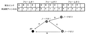
ISA100.11aは、プロセス制御及び関連するアプリケーション用の無線システムに特定され、OSI標準モデルにより動作する。この規格では、メッシュ・ネットワークにおいてタイムスロット・チャンネル・ホッピング・メカニズムがデータ・リンク層として採用される。このようなメカニズムでは、二つのノード間の各リンクに一つのタイムスロットが割り当てられる。更に、図1に一例として示されるように、送信周波数チャンネルは、タイムスロット毎にホッピングする。タイムスロット・チャンネル・ホッピング・コンセプトの説明を容易にするために、図1のフレーム構造及びホッピング・パターンは簡略化されている。上の表は、各フレームが5つのタイムスロットを含むフレーム構造を示す。第1行は、各タイムスロットへの割当リンクを示し、第2行は、送信周波数チャンネルを示す。この例は、{0,1,2,3,4,5}の共用周波数ホッピング・パターンを用いる。このケースでは、ノード#1からアクセス・ポイントAPへの通信、すなわちリンクAのホッピング・パターンは、{0,5,4,3,2,1}としなければならない。このシステムは、元のホッピング・パターンからオフセットした別の周波数ホッピング・パターンと共に、マルチフレーム構造を用いてもよい。このようなシステムでは、コンテンション(contention)を生じることなく、一つのタイムスロット内で多数の通信が可能である。このシステムは、WiFiシステム等の同じ周波数バンドを有する別の無線システムからの干渉の影響を大きく受ける。「ISA100.11a−2009、ISA規格、産業自動化用の無線システム:プロセス制御及び関連するアプリケーション用の無線システム、2009年10月」を参照されたい。
ISA100.11a is specific to wireless systems for process control and related applications and operates according to the OSI standard model. This standard employs a time slot channel hopping mechanism as a data link layer in mesh networks. In such a mechanism, one time slot is assigned to each link between two nodes. Furthermore, as shown in FIG. 1 as an example, the transmission frequency channel hops every time slot. To facilitate the description of the time slot channel hopping concept, the frame structure and hopping pattern of FIG. 1 has been simplified. The table above shows a frame structure in which each frame contains 5 time slots. The first row shows the allocation link to each time slot, and the second row shows the transmission frequency channel. This example uses a shared frequency hopping pattern of {0, 1, 2, 3, 4, 5}. In this case, the communication from the
ブルートゥース用の適応型周波数ホッピング Adaptive frequency hopping for Bluetooth
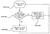
特許文献1には、特にブルートゥース・システム用のオーバーレイ適応型周波数ホッピング・アプローチの開示がある。このコンセプトは、最初に選択されたホッピング周波数のチャンネル状態の特性が不良である場合、カーネル(Kernel)は、最初に選択されたホッピング周波数をチャンネル状態の特性が良好な代りのホッピング周波数にマッピングする。図2は、特許文献1のブルートゥース用の適応型周波数ホッピング・システムの動作フロー・チャートである。このシステムは、GP FHカーネルを実行し(ステップ510)、得られたチャンネルが良好チャンネル・リストにあるかどうかを決定する(ステップ530)。YESであれば、システムは、得られたチャンネルを選択し、出力する(ステップ540)。NOであれば、システムは、良好チャンネル・リストから代りのチャンネルを選択し、出力する(ステップ550)。しかし、このメカニズムは、基本的にはポイントツーポイント通信のためのものであり、時間分割多重アクセス・システム又は適応型周波数ホッピングのネットワーク管理全体のためのメカニズムの開示はない。すなわち、前に説明したように、タイムスロット周波数ホッピングを採用する産業用の無線システムでは、多数のノードが一つの周波数ホッピング・シーケンスで通信し各ノードのチャンネル状態が異なるため、このメカニズムしか使用しないシステムは動作しない。したがって、特許文献1には、大規模ネットワークにおいて、チャンネル状態が異なるこのような多数のノードを扱うのに必要なメカニズムについての開示はない。
U.S. Pat. No. 6,053,077 discloses an overlay adaptive frequency hopping approach, particularly for Bluetooth systems. The concept is that if the channel state characteristics of the initially selected hopping frequency are poor, the kernel will map the initially selected hopping frequency to an alternative hopping frequency with good channel state characteristics. . FIG. 2 is an operation flowchart of the adaptive frequency hopping system for Bluetooth disclosed in
周波数チャンネルの判定及び選択 Judgment and selection of frequency channels
適応型周波数ホッピングのための周波数チャンネルの判定及び選択には、チャンネル状態を測定するためのメカニズムが必要である。特許文献2には、RSSI(Radio Signal Strength Indicator:無線信号強度インジケータ)を測定する方法の開示がある。更に、RSSI測定とパケット/ビット誤り率測定とを組み合わせて使用することの開示がある。WiFi信号等の干渉信号を考慮すると、無線信号が常に空中に発生されているとは言えないので、空間占有率等の統計的測定がより重要である。このような意味において、パケット誤り率は、チャンネルの判定に適当な指標である。しかし、このようなシステムにおけるチャンネルの判定のために全てのチャンネルにわたる十分な測定サンプルを収集するには、長い時間を要する傾向がある。このため干渉状態が大幅に変化したときに性能が劣化する。
The determination and selection of frequency channels for adaptive frequency hopping requires a mechanism for measuring channel conditions.
A.タイムスロット方式を採用した無線ネットワークにおける適応型周波数ホッピング A. Adaptive frequency hopping in wireless networks using time slot method
上記問題を解決するために、我々は分散適応型周波数ホッピング・ネットワークを提案する。図3に、図1の変形バージョンである本発明の一実施形態によるタイムスロット方式を採用したネットワークにおける適応型周波数ホッピングの一例を示す。全てのノード及びAP(アクセス・ポイント)は、これまで説明したような共用スーパー・フレームを有する。更に、全てのノード及びAPは、スーパー・フレーム構造のための一つの周波数ホッピング・パターンを共用する。図3の例の共用ホッピング・パターンは、{0,1,2,3,4,5}である。 In order to solve the above problem, we propose a distributed adaptive frequency hopping network. FIG. 3 shows an example of adaptive frequency hopping in a network employing a time slot method according to an embodiment of the present invention which is a modified version of FIG. All nodes and APs (access points) have a shared super frame as described above. Furthermore, all nodes and APs share one frequency hopping pattern for the super frame structure. The shared hopping pattern in the example of FIG. 3 is {0, 1, 2, 3, 4, 5}.
図3に、リンク毎のチャンネル・リストも示す。例えば、測定結果として、リンクAは、{3,4,5}の利用可能チャンネル・リスト及び{0,1,2}の不良チャンネル・リストを有する。これらのリストは、リンクAに関連するコミニュケータ(Communicators)であるノード#1とAPとの間で共用される。フレーム#1の第1タイムスロットでは、共用ホッピング・チャンネルは、リンクAの不良チャンネル・リストにあるチャンネル0である。このように、ノード#1は、チャンネル0の代わりに、利用可能チャンネル・リストから選択されたチャンネル3でデータを送信する。APも同じように利用可能チャンネル・リストからチャンネル3を選択する。フレーム#1の4番目のタイムスロットでは、共用ホッピング・チャンネルは、リンクDの不良チャンネル・リストにないチャンネル3である。このケースでは、ノード#3は、チャンネル3でデータを送信し、ノード#1は、同じチャンネルでデータを待つ。このように、全てのリンクで同じプロセスが実行される。
FIG. 3 also shows a channel list for each link. For example, as a measurement result, link A has an available channel list of {3,4,5} and a bad channel list of {0,1,2}. These lists are shared between the
この例とは異なり、利用可能チャンネル・リストは、良好チャンネルだけを含むとは限らない。このことは、利用可能チャンネル・リストは不良チャンネルを含むことがあり得ることを意味する。不良チャンネルを含む場合、ノードは、不良チャンネルの変化する状態を知って、後で、不良チャンネルが良好な状態となった場合、このチャンネルを再利用できる。 Unlike this example, the available channel list may not include only good channels. This means that the available channel list can contain bad channels. If it contains a bad channel, the node knows the changing state of the bad channel and can later reuse this channel if the bad channel becomes good.
B.タイムスロット方式を採用した無線ネットワークにおける適応型周波数ホッピング装置 B. Adaptive frequency hopping equipment in wireless network using time slot method
1)通信デバイス 1) Communication device
図4は、本発明の一実施形態によるノード又はアクセス・ポイントに含まれる通信デバイスのブロック図を示す。図4の各ブロックは、本発明の分散適応型周波数ホッピングを実行するのに採用された無線通信デバイスの機能ユニットである。通信デバイスは、トランシーバとコントローラとを含む。トランシーバは、空中に無線信号を送信する送信機(Tx)と、空中から無線信号を受信する受信機(Rx)とを含む。トランシーバは、送受信用の周波数チャンネルについてはコントローラによって構成される。 FIG. 4 shows a block diagram of a communication device included in a node or access point according to an embodiment of the present invention. Each block in FIG. 4 is a functional unit of the wireless communication device employed to perform the distributed adaptive frequency hopping of the present invention. The communication device includes a transceiver and a controller. The transceiver includes a transmitter (Tx) that transmits radio signals in the air and a receiver (Rx) that receives radio signals from the air. The transceiver is configured by a controller for frequency channels for transmission and reception.
コントローラは、管理モジュールと、チャンネル設定モジュールと、チャンネル・テーブルと、MAC/DLモジュールとを含む。コントローラのMAC/DL機能は、無線リンクの媒体アクセス制御層と上位層とを取り扱う。管理機能は通信全てにわたる構成及び管理に関与する。図5は、通信デバイスにおける典型的な通信フローを示す。まず最初に、ステップ502において、次の割当タイムスロットの構成が処理される。この機能の詳細については後述する。ステップ504において、デバイスは、次の割当タイムスロットを待つ。ステップ506において、割当タイムスロットに到達すると、デバイスは、データがあればその送信を試みるか、又は他のノードが送信したデータを待つ。一旦、このタイムスロットで全ての通信が実行されると、次の割当タイムスロットのチャンネル構成が再び処理される。コントローラは、チャンネル設定機能及びチャンネル・テーブルも有する。チャンネル・テーブルは、少なくとも共用周波数ホッピング・パターン及びコントローラ自身のデバイスが通信できるいくつかのノードのチャンネル・リストを含む。チャンネル・リストは、チャンネル状態の情報を含む。
The controller includes a management module, a channel setting module, a channel table, and a MAC / DL module. The MAC / DL function of the controller handles the medium access control layer and the upper layer of the radio link. Management functions are involved in configuration and management across all communications. FIG. 5 shows a typical communication flow in a communication device. Initially, in
図6は、図4の通信デバイスにおけるチャンネル設定機能の構造の一例を示す。図7は、図5の次の割当タイムスロットを構成するためのステップ502に対応するチャンネル設定機能のフロー・チャートの一例を示す。ステップ702において、チャンネル・テーブルにある共用周波数ホッピング・パターンから次の割当タイムスロットのためのカレント(Current)通信周波数チャンネルがロードされる。このことは、図6の入力としてタイムスロット番号及びフレーム番号、並びにホッピング・パターン・テーブルを有する「カレント・チャンネル」ブロックが示している。ステップ704において、チャンネル・テーブルから、コントローラ自身のデバイスが通信を試みる相手のターゲット・ノードのチャンネル・リストがロードされる。このことは、図6の入力としてターゲット・ノードのアドレス及びチャンネル・リスト・テーブルを有する「チャンネル・リスト」ブロックが示している。
FIG. 6 shows an example of the structure of the channel setting function in the communication device of FIG. FIG. 7 shows an example of a flow chart of the channel setting function corresponding to step 502 for configuring the next assigned time slot of FIG. In
図8に、チャンネル・リスト・テーブルの一例を示す。図8に、図3の例について、ノード#1のチャンネル・リストだけを示す。より完全なテーブルであれば、他のノードのチャンネル・リストも同じように示される。このテーブルは、それぞれターゲットAP、ノード#2、ノード#3に対する三つのチャンネル・リストを示す。各チャンネル・リストは、各チャンネルに対して「良好」又は「不良」という判定がされた複数のチャンネルを有する。これらのチャンネルの判定については後述する。
FIG. 8 shows an example of the channel list table. FIG. 8 shows only the channel list of
図7のステップ706(図6の「利用可能なチャンネルか?」ブロック)において決定されたチャンネル・リストに従い、カレント・チャンネルが利用可能でない場合、ステップ708において、利用可能チャンネル・リストから代りのチャンネルが選択される。一般に、利用可能チャンネル・リストは、チャンネル・リストから作成される。このことは、図6の入力としてタイムスロット番号及びフレーム番号並びにチャンネル・リストを有する「代りのチャンネル」ブロックが示している。ステップ706において、カレント・チャンネルが利用可能と決定された場合、代りのチャンネルを計算するステップ708はスキップされる。次に、ステップ710において、選択されたチャンネルがトランシーバに設定される。
If the current channel is not available according to the channel list determined in
2)代りのチャンネルの例 2) Examples of alternative channels
ここでは、代りのチャンネルの計算例を説明する。図9は、その一例を示す。前に説明したように、代りのチャンネルは、利用可能チャンネル・リストから選択される。選択方法の一例は、フレーム番号情報を利用するものである。図9から分かるように、計算機は、フレーム番号及び共用周波数ホッピング・パターンの周期並びに利用可能チャンネル・リストの長さから計算されたアドレスを有する代りのチャンネルを選択する。 Here, an alternative channel calculation example will be described. FIG. 9 shows an example. As previously described, an alternative channel is selected from the available channel list. An example of the selection method uses frame number information. As can be seen from FIG. 9, the calculator selects an alternate channel having an address calculated from the frame number and the period of the shared frequency hopping pattern and the length of the available channel list.
利用可能チャンネル・リストの例もいくつか存在する。それらの例の一つは、良好な状態のチャンネルだけを含むリストである。利用可能チャンネル・リストの別の例は、共用周波数ホッピング・パターンと同じリストである。この例は、「不良」チャンネルを使用することになる。しかし、不良チャンネルを使用する機会の回数は依然として少なく、代わりにデバイスは、そのチャンネルの誤り率を測定する機会を得ることができる。更に、この例のシステムでは、元のパターンからオフセットした別の周波数ホッピング・パターンを有するマルチフレーム構造が実行されるとき、利用可能チャンネル・リストが他のフレーム構造の周波数ホッピング・パターンからもオフセットしている場合、各スロットでコンテンションしない多数の通信が可能である。例えば、第1フレーム構造の共用周波数ホッピング・パターンが{0,1,2,3,4,5}であり、第2フレーム構造の共用周波数ホッピング・パターンが1のオフセットを意味する{1,2,3,4,5,0}である場合、第1フレーム構造の利用可能チャンネル・リストが{0,1,2,3,4,5}であり、1のオフセットを有する第2フレーム構造の利用可能チャンネル・リストが{1,2,3,4,5,0}であれば、コンテンションは生じない。 There are also some examples of available channel lists. One of those examples is a list containing only channels in good condition. Another example of an available channel list is the same list as the shared frequency hopping pattern. This example would use a “bad” channel. However, the number of opportunities to use a bad channel is still small, and instead the device can have an opportunity to measure the error rate of that channel. Furthermore, in this example system, when a multi-frame structure with another frequency hopping pattern offset from the original pattern is executed, the available channel list is also offset from the frequency hopping pattern of the other frame structure. Multiple communication without contention in each slot is possible. For example, the shared frequency hopping pattern of the first frame structure is {0, 1, 2, 3, 4, 5}, and the shared frequency hopping pattern of the second frame structure is an offset of {1,2. , 3, 4, 5, 0}, the available channel list of the first frame structure is {0, 1, 2, 3, 4, 5}, and the second frame structure has an offset of 1. If the available channel list is {1, 2, 3, 4, 5, 0}, no contention occurs.
C.チャンネルの判定及び選択 C. Channel judgment and selection
AFHシステムにおけるチャンネルの判定及び選択方法は、重要な特徴である。本発明は、誤り率に基づく測定とビジーのCCAの数のカウントによる空間占有率の測定とを組み合わせて使用することを提案する。パケットが送信されるとき、誤り率に基づく測定が行われる。しかし、ある特定のチャンネルでパケットを送受信する機会の回数は、周波数ホッピング・メカニズムのため比較的少ない。このためチャンネル特性を得るための測定時間が長くなり、ダイナミックに変化する干渉状態では、性能の劣化が生じ得る。このとき、CCAメカニズムによる空間占有率の測定は、誤り率に基づく測定のこのような弱点を補う。図3に、このコンセプトを示す。図3では、各フレームの5番目のタイムスロットをCCAの測定期間に割り当てている。このスロットでは、どこもデータの送信を試みないので、全てのノードは、干渉状態だけを測定できる。このスロットでは、各ノードは、共用周波数ホッピング・パターンの全てのチャンネルにわたってCCAを行う。典型的なCCAモードは、RSSI(無線信号強度インジケータ)を測定するED(Energy Detection:エネルギー検出)である。この測定を繰り返し、チャンネル毎にCCAがビジーになる回数をカウントすることにより、チャンネルの判定のための空間占有率等の干渉の統計的指標が得られる。例えば、ある特定のチャンネルにおける所定の期間でビジーのCCAの数が所定の値を超えた場合、そのチャンネルを不良チャンネルとして判定できる。 The channel determination and selection method in the AFH system is an important feature. The present invention proposes to use a combination of error rate based measurements and space occupancy measurements by counting the number of busy CCA. When a packet is transmitted, a measurement based on the error rate is performed. However, the number of opportunities to send and receive packets on a particular channel is relatively small due to the frequency hopping mechanism. For this reason, the measurement time for obtaining the channel characteristics becomes long, and performance degradation may occur in a dynamically changing interference state. At this time, the measurement of the space occupancy by the CCA mechanism compensates for this weakness of the measurement based on the error rate. FIG. 3 illustrates this concept. In FIG. 3, the fifth time slot of each frame is assigned to the CCA measurement period. Since no data transmission is attempted in this slot, all nodes can only measure interference conditions. In this slot, each node performs CCA across all channels of the shared frequency hopping pattern. A typical CCA mode is ED (Energy Detection) that measures RSSI (Radio Signal Strength Indicator). By repeating this measurement and counting the number of times CCA becomes busy for each channel, a statistical index of interference such as space occupancy for channel determination can be obtained. For example, when the number of busy CCAs in a specific channel exceeds a predetermined value in a predetermined period, the channel can be determined as a defective channel.
一般に、CCAがビジーである状態は、測定されたRSSIと所定のスレッショルド値との比較によって決定される。すなわち測定されたRSSIが、スレッショルド値よりも大であれば、CCAはビジーである。スレッショルド値は、あらかじめ決定した固定値でもよいし、受信機との通信を試みる送信機からの受信信号パワーに基づき可変としてもよい。 In general, the state in which the CCA is busy is determined by comparing the measured RSSI with a predetermined threshold value. That is, if the measured RSSI is greater than the threshold value, the CCA is busy. The threshold value may be a fixed value determined in advance, or may be variable based on the received signal power from the transmitter attempting to communicate with the receiver.
典型的な誤り率に基づく測定は、パケット誤り率(PER)を測定する。PERとCCAの両方の結果を考慮して、図10の例に示されるように、最終チャンネル判定が行われる。この図は、APの測定結果及びノード#1とノード#2のチャンネル・リストを示す。この例では、ノードのチャンネル・リストは互いに異なる。更に、ビット誤り率(BER)測定又はLQI(Link Quality Indicator:リンク品質インジケータ)測定を誤り率に基づく測定として使用できる。
A typical error rate based measurement measures the packet error rate (PER). Considering the results of both PER and CCA, the final channel determination is performed as shown in the example of FIG. This figure shows the AP measurement results and the channel list of
D.チャンネル・リストの通知 D. Channel list notification
二つのノード間で一つのチャンネル・リストを共用するには、チャンネル・リストを一方のノードから他方のノードに通知しなければならない。チャンネル・リストを通知するための詳細なシーケンスは、当該技術分野で知られているので、ここでは説明しないが、解説のためにいくつかの例を示す。 In order to share one channel list between two nodes, the channel list must be notified from one node to the other. The detailed sequence for notifying the channel list is known in the art and will not be described here, but some examples are provided for illustration.
一つのアイデアは、実効時間(Effective Time)の情報を有するデータ・パケット又はACK/NACKパケットに将来のチャンネル・リストを挿入することである。別のアイデアは、将来のチャンネル・リストを共用するために、互いに交渉することである。例えば、交換されたチャンネル・リストを有する受信機がその通知と共にパケットを送信機に送信する。送信機は、一旦この情報を受信すると、この通知の受信確認を送信する。別のアイデアは、システム・マネージャーがシステムの全てのノードの測定結果を収集し、全てのリンクのチャンネル・リストを作成するものである。次に、システム・マネージャーは、全てのノードにチャンネル・リストを通知する。 One idea is to insert a future channel list into a data packet or ACK / NACK packet with effective time information. Another idea is to negotiate with each other to share future channel lists. For example, a receiver with an exchanged channel list sends a packet with the notification to the transmitter. Once the transmitter receives this information, it sends an acknowledgment of this notification. Another idea is that the system manager collects measurement results for all nodes in the system and creates a channel list for all links. Next, the system manager notifies the channel list to all nodes.
E.マルチチャンネルの実施形態 E. Multi-channel embodiment
信頼性を更に改善するために、マルチチャンネル通信コンセプトを使用できる。図11は、提案するマルチチャンネル通信ノードの一実施形態を示す。この実施形態は、二つ以上のトランシーバを含み、両方のトランシーバは、異なるチャンネルで同じデータを送信し、異なるチャンネルで同じデータを受信する。 To further improve reliability, a multi-channel communication concept can be used. FIG. 11 shows an embodiment of the proposed multi-channel communication node. This embodiment includes two or more transceivers, both transceivers transmitting the same data on different channels and receiving the same data on different channels.
図12は、マルチチャンネル周波数ホッピング・パターンの一例を示す。サブトランシーバの周波数ホッピング・パターンは、メイントランシーバのものからオフセットしている。説明を容易にするために、この図は、AFH動作を含まない。AFH動作により、前に説明したメカニズムをトランシーバのいずれか又は両方に適用できる。このマルチチャンネル・コンセプトを使用することによって、トランシーバの簡略化を犠牲にして信頼性を大幅に改善できる。 FIG. 12 shows an example of a multi-channel frequency hopping pattern. The sub-transceiver frequency hopping pattern is offset from that of the main transceiver. For ease of explanation, this figure does not include AFH operation. With AFH operation, the previously described mechanism can be applied to either or both of the transceivers. By using this multi-channel concept, reliability can be significantly improved at the expense of transceiver simplification.
図13は、提案するAFHの効果及びAFHによるマルチチャンネル通信の効果を示し、ある特定の干渉状態下でのシミュレーション結果をプロットしたものである。単一チャンネルの例に対してAFHを使用するとき、及びマルチチャンネルの例に対してAFHを使用するときに、パケット損失レートが低下する。 FIG. 13 shows the effect of the proposed AFH and the effect of multichannel communication using AFH, and plots the simulation results under a specific interference condition. The packet loss rate is reduced when using AFH for the single channel example and when using AFH for the multi-channel example.
F.本発明の利点 F. Advantages of the present invention
本発明は、信頼性のある通信を可能にするため、より低コストかつより低複雑度の大規模ネットワークのための適応型周波数ホッピング・メカニズムを提供する。一実施形態では、ネットワークのノードは、一つ以上の周波数ホッピング・パターンを共用し、互いに通信を試みる二つのノードは、チャンネル状態を含むチャンネル・リストを共用する。本発明の二つの主な利点は、改善された信頼性及び高速測定である。信頼性を改善する適応型周波数チャンネル・メカニズムを、低コストかつ低複雑度のタイムスロット周波数ホッピングに基づくネットワーク及びメッシュ・ネットワークに組み込むことができる。図13には、信頼性の改善が示されている。更に、例えば、誤り率に基づく測定と空間占有率の測定とを組み合わせて使用することにより、上記のチャンネルの判定及び選択のための信頼性のある高速チャンネル状態測定を実現できる。 The present invention provides an adaptive frequency hopping mechanism for large networks with lower cost and lower complexity to enable reliable communication. In one embodiment, the nodes of the network share one or more frequency hopping patterns, and the two nodes attempting to communicate with each other share a channel list containing channel conditions. The two main advantages of the present invention are improved reliability and high speed measurement. An adaptive frequency channel mechanism that improves reliability can be incorporated into networks and mesh networks based on low cost and low complexity time slot frequency hopping. FIG. 13 shows the improvement in reliability. Further, for example, by using a combination of measurement based on error rate and measurement of space occupancy, reliable high-speed channel state measurement for channel determination and selection can be realized.
本発明による無線システムは、プラント/工場の自動化、ビルの自動化、環境監視等の信頼性を必要とする産業用の無線アプリケーションに利用できる。典型的なアプリケーションの一つは監視アプリケーションである。典型的な監視アプリケーションでは、ターミナル・ノードは、センサ及び提案するトランシーバを有し、測定データをセンターに送る。別のアプリケーションは制御アプリケーションである。典型的な制御アプリケーションでは、ターミナル・ノードは、無線通信によって送信された信号により制御されるアクチュエータも有する。 The wireless system according to the present invention can be used for industrial wireless applications that require reliability such as plant / factory automation, building automation, and environmental monitoring. One typical application is a monitoring application. In a typical monitoring application, the terminal node has a sensor and a proposed transceiver and sends measurement data to the center. Another application is a control application. In a typical control application, the terminal node also has an actuator that is controlled by signals transmitted by wireless communication.
本発明を実施するコンピュータ及び記憶システムは、上記発明の実施に使用されるモジュール、プログラム及びデータ構造の記憶及び読取が可能な公知のI/Oデバイス(例えば、CD及びDVDドライブ、フロッピー(登録商標)・ディスク・ドライブ、ハード・ドライブ)も有することができる。これらのモジュール、プログラム及びデータ構造は、このようなコンピュータ読取可能媒体上に符号化できる。例えば、本発明のデータ構造は、本発明で使用されるプログラムが常駐している一つ以上のコンピュータ読取可能媒体とは独立に、コンピュータ読取可能媒体上に記憶できる。システムのコンポーネントは、デジタル・データ通信、例えば、任意の形式又は媒体の通信ネットワークにより、相互接続できる。通信ネットワークの例としては、ローカル・エリア・ネットワーク、インターネット等のワイド・エリア・ネットワーク、無線ネットワーク、記憶エリア・ネットワーク等が挙げられる。 The computer and storage system embodying the present invention are known I / O devices (for example, CD and DVD drives, floppy (registered trademark)) capable of storing and reading modules, programs and data structures used in the above-described invention. ) Disk drive, hard drive). These modules, programs and data structures can be encoded on such computer-readable media. For example, the data structure of the present invention can be stored on a computer readable medium independent of one or more computer readable media on which the program used in the present invention resides. The components of the system can be interconnected by digital data communication, eg, any form or medium of communication network. Examples of communication networks include local area networks, wide area networks such as the Internet, wireless networks, storage area networks, and the like.
発明の詳細な説明において、本発明を完全に理解できるように説明するために多数の細部について説明した。しかし、本発明を実施するのにこれらの具体的な細部の全てが必要となるわけではないことは当業者に明らかである。また、本発明は、通常、フロー・チャート、フロー図、構造図又はブロック図に描かれるプロセスとして説明できるとも言える。動作がフロー・チャートにシーケンシャルなプロセスとして説明されていても、動作の多くは並列又は同時に実行することができる。また、動作の順序は変更してもよい。 In the detailed description of the invention, numerous details are set forth in order to provide a thorough understanding of the present invention. However, it will be apparent to one skilled in the art that not all of these specific details are required to practice the invention. It can also be said that the present invention can usually be described as a process drawn in a flow chart, flow diagram, structure diagram or block diagram. Even though the operations are described as a sequential process in the flow chart, many of the operations can be performed in parallel or simultaneously. The order of operations may be changed.
当該技術分野で知られているように、上記動作は、ハードウェア、ソフトウェア、又はソフトウェアとハードウェアのある組み合わせにより実行できる。本発明の実施形態の種々の特徴は、回路及び論理デバイス(ハードウェア)を使って実現し、他の特徴は、プロセッサに実行させるなら、本発明の実施形態を実施するための方法をプロセッサに実行させるマシン読取可能媒体上に記憶された命令(ソフトウェア)を使って実現してよい。更に、本発明のいくつかの実施形態は、ハードウェアのみにより実施してよいし、他の実施形態はソフトウェアのみで実施してよい。更に、説明した種々の機能は、単一ユニットで実施できるか、又は種々の方法で多数の部品にわたって分散させることもできる。ソフトウェアで実施するとき、コンピュータ読取可能媒体に記憶された命令に基づき、汎用コンピュータ等のプロセッサによってこれらの方法を実行してもよい。必要なら、命令は、圧縮フォーマット及び/又は暗号化フォーマットで媒体に記憶できる。 As is known in the art, the above operations can be performed by hardware, software, or some combination of software and hardware. Various features of embodiments of the present invention are realized using circuitry and logic devices (hardware), and other features may be performed by a processor if the processor is implemented. It may be implemented using instructions (software) stored on a machine readable medium to be executed. Furthermore, some embodiments of the present invention may be implemented solely by hardware, while other embodiments may be implemented solely by software. Further, the various functions described can be performed in a single unit or can be distributed across multiple parts in various ways. When implemented in software, the methods may be performed by a processor such as a general purpose computer based on instructions stored on a computer-readable medium. If necessary, the instructions can be stored on the medium in a compressed and / or encrypted format.
以上から、本発明は、タイムスロット方式を採用した無線ネットワークにおける適用型周波数ホッピングのための方法、装置及びコンピュータ読取可能媒体に記憶されるプログラムを提供することが明らかなる。更に、具体的な実施形態を図示し本明細書において説明したが、開示した具体的な実施形態を同じ目的を達成すると予想される任意の構成に代えてもよいことは当業者にとって当然である。この開示は、本発明の任意の、かつ全ての適用例又は変形例をカバーすることを意図したものであり、当然、特許請求の範囲で使用する用語は、本発明を本明細書に開示された具体的な実施形態のみに限定するものと解してはならない。むしろ、本発明の範囲は、もっぱら特許請求の範囲によって決定すべきであり、特許請求の範囲の解釈について確立された原則に従い、このような特許請求の範囲に認められる均等物の全ての範囲を含むと解すべきである。 From the above, it will be apparent that the present invention provides a method, apparatus and program stored on a computer readable medium for adaptive frequency hopping in a wireless network employing a time slot scheme. Further, while specific embodiments have been illustrated and described herein, it will be appreciated by those skilled in the art that the disclosed specific embodiments may be replaced with any configuration that is expected to achieve the same purpose. . This disclosure is intended to cover any and all applications or variations of the present invention, and of course, the terms used in the claims are intended to disclose the present invention herein. It should not be construed as being limited to only specific embodiments. Rather, the scope of the present invention should be determined solely by the claims, and should be in accordance with established principles for interpreting the claims and to cover the full scope of equivalents found in such claims. Should be understood to include.
Claims (20)
各送信ノードは、複数のターゲット・ノードのチャンネル・リストを含むチャンネル・リスト・テーブルを有し、各チャンネル・リストは、ターゲット・ノードとの通信に利用可能な少なくとも一つのチャンネルを含む前記共用周波数ホッピング・パターンのチャンネルの状態を含み、
前記送信ノードにおいて、前記共用周波数ホッピング・パターンから、次の割当タイムスロットのチャンネルを選択するステップと、
前記チャンネル・リスト・テーブルから、前記送信ノードが送信する先のターゲット・ノードのアドレスに基づいて前記ターゲット・ノードの前記チャンネル・リストをロードするステップと、
前記ロードされたチャンネル・リストに基づき、前記選択されたチャンネルが利用可能であるかどうかをチェックするステップと、
前記選択されたチャンネルが利用可能な場合、前記送信ノードにおいて、前記選択されたチャンネルを設定するステップと、
前記選択されたチャンネルが利用可能でない場合、前記送信ノードにおいて、前記選択されたチャンネルの代わりに、前記チャンネル・リストから代りのチャンネルを計算するステップとを含む無線通信方法。 A wireless network system having a plurality of nodes including a transmission node and a target node that communicate with each other, wherein one frequency hopping pattern is shared between the plurality of nodes, and the shared frequency hopping pattern is a series of A wireless communication method in the wireless network system, wherein the time slot includes a channel associated with a time slot, each time slot having an assigned link between two of the nodes;
Each transmitting node has a channel list table including a channel list of a plurality of target nodes, and each channel list includes at least one channel available for communication with the target node. Including the channel state of the hopping pattern,
Selecting a channel of the next assigned time slot from the shared frequency hopping pattern at the transmitting node;
Loading the channel list of the target node from the channel list table based on the address of the target node to which the transmitting node transmits;
Checking whether the selected channel is available based on the loaded channel list;
If the selected channel is available, setting the selected channel at the transmitting node;
And, if the selected channel is not available, calculating at the transmitting node an alternative channel from the channel list instead of the selected channel.
前記次の割当タイムスロットにおいて、前記送信ノードから前記ターゲット・ノードへデータを送信するステップとを更に含む、請求項1に記載の無線通信方法。 Waiting for the next assigned time slot to arrive;
The wireless communication method according to claim 1, further comprising: transmitting data from the transmission node to the target node in the next assigned time slot.
前記代りのチャンネルを計算するステップは、前記ロードされたチャンネル・リストから作成された利用可能チャンネル・リストから代りのチャンネルを選択するステップを含む、請求項1に記載の無線通信方法。 The time slots of the shared frequency hopping pattern are arranged in a series of frames, each frame having a frame number and including a plurality of time slots;
The wireless communication method of claim 1, wherein calculating the alternative channel comprises selecting an alternative channel from an available channel list created from the loaded channel list.
チャンネルの誤り率を得るためのデータが送信されたとき、前記誤り率に基づく測定を行い、
データ送信リンクが割り当てられていないタイムスロットで前記空間占有率の測定を行い、各ノードは、前記共用周波数ホッピング・パターン内の全てのチャンネルにわたって、1回以上の空きチャンネル判定(CCA)を実行して、チャンネル毎に前記空きチャンネル判定(CCA)がビジーの回数をカウントし、前記チャンネルの空間占有率に関係する干渉の統計的指標を得、
あるチャンネルについて、前記誤り率に基づく測定及び前記空間占有率の測定の一方又は両方が前記チャンネルの不良を示した場合、前記チャンネルを不良チャンネルとし、そうでない場合、前記チャンネルを良好チャンネルとする、請求項1に記載の無線通信方法。 Creating the channel list by determining channels based on measurement based on error rate and space occupancy;
When data for obtaining an error rate of a channel is transmitted, measurement based on the error rate is performed,
The space occupancy is measured in a time slot to which no data transmission link is allocated, and each node performs one or more free channel determinations (CCAs) across all channels in the shared frequency hopping pattern. For each channel, the free channel determination (CCA) counts the number of busy times to obtain a statistical index of interference related to the space occupancy of the channel,
For one channel, if one or both of the measurement based on the error rate and the measurement of the space occupancy indicate a failure of the channel, the channel is set as a bad channel; otherwise, the channel is set as a good channel. The wireless communication method according to claim 1.
各送信ノードのコントローラは、
各送信ノードについて、複数のターゲット・ノードのチャンネル・リストを含むチャンネル・リスト・テーブルを有し、各チャンネル・リストは、ターゲット・ノードとの通信に利用可能な少なくとも一つのチャンネルを含む前記共用周波数ホッピング・パターンのチャンネルの状態を含み、
前記送信ノードにおいて、前記共用周波数ホッピング・パターンから、前記メイントランシーバのために次の割当タイムスロットのチャンネルを選択し、
前記チャンネル・リスト・テーブルから、前記メイン送信機により前記送信ノードが送信する先のターゲット・ノードのアドレスに基づいて前記ターゲット・ノードの前記チャンネル・リストをロードし、
前記メイン送信機のためにロードされたチャンネル・リストに基づき、前記選択されたチャンネルが利用可能であるかどうかをチェックし、
前記メイン送信機のために選択されたチャンネルが利用可能な場合、前記送信ノードにおいて、前記選択されたチャンネルを設定し、
前記メイン送信機のための選択されたチャンネルが利用可能でない場合、前記送信ノードにおいて、前記選択されたチャンネルの代わりに、前記チャンネル・リストから代りのチャンネルを計算するように構成されるチャンネル設定モジュールを含む、送信ノード。 A transmission node in a wireless network system having a plurality of nodes including a transmission node and a target node that communicate with each other, wherein the main transceiver includes a main transmitter and a main receiver, and the main transceiver includes the other nodes. Shares a frequency hopping pattern with the main transceiver, the shared frequency hopping pattern including a channel associated with a series of time slots, each of which is between two of the nodes. In the transmitting node having an allocation link,
The controller of each sending node
Each transmitting node has a channel list table including a channel list of a plurality of target nodes, and each channel list includes at least one channel available for communication with the target node. Including the channel state of the hopping pattern,
In the transmitting node, from the shared frequency hopping pattern, select a channel for the next assigned time slot for the main transceiver;
From the channel list table, load the channel list of the target node based on the address of the target node to which the transmitting node transmits by the main transmitter;
Check whether the selected channel is available based on the channel list loaded for the main transmitter;
If the selected channel is available for the main transmitter, set the selected channel at the transmitting node;
A channel setting module configured to calculate an alternative channel from the channel list instead of the selected channel at the transmitting node if the selected channel for the main transmitter is not available Including the sending node.
前記チャンネル設定モジュールは、前記ロードされたチャンネル・リストから作成された利用可能チャンネル・リストから代りのチャンネルを選択する、請求項8に記載の送信ノード。 The time slots of the shared frequency hopping pattern are arranged in a series of frames, each frame having a frame number and including a plurality of time slots;
9. The transmission node of claim 8, wherein the channel setting module selects an alternative channel from an available channel list created from the loaded channel list.
チャンネルの誤り率を得るためのデータが送信されたとき、前記誤り率に基づく測定を行い、
データ送信リンクが割り当てられていないタイムスロットで前記空間占有率の測定を行い、各ノードは、前記共用周波数ホッピング・パターン内の全てのチャンネルにわたって各ノードは、1回以上の空きチャンネル判定(CCA)を実行して、チャンネル毎に空きチャンネル判定(CCA)がビジーの回数をカウントし、前記チャンネルの空間占有率に関係する干渉の統計的指標を得、
あるチャンネルについて、前記誤り率に基づく測定及び前記空間占有率の測定の一方又は両方が前記チャンネルの不良を示した場合、前記チャンネルを不良チャンネルとし、そうでない場合、前記チャンネルを良好チャンネルとする、請求項8に記載の送信ノード。 Creating the channel list by determining channels based on measurement based on error rate and space occupancy;
When data for obtaining an error rate of a channel is transmitted, measurement based on the error rate is performed,
The space occupancy is measured in a time slot to which no data transmission link is allocated, and each node has one or more free channel determinations (CCA) across all channels in the shared frequency hopping pattern. For each channel, the free channel determination (CCA) counts the number of busy times, and obtains a statistical indicator of interference related to the space occupancy of the channel,
For one channel, if one or both of the measurement based on the error rate and the measurement of the space occupancy indicate a failure of the channel, the channel is set as a bad channel; otherwise, the channel is set as a good channel. The transmission node according to claim 8.
前記メイントランシーバは、前記システムの他のノードのメイントランシーバと前記共用周波数ホッピング・パターンを共用し、
前記サブトランシーバは、前記システムの他のノードのサブトランシーバとオフセット周波数ホッピング・パターンを共用し、前記オフセット周波数ホッピング・パターンは、前記メイントランシーバの前記共用周波数ホッピング・パターンからオフセットしており、前記メイントランシーバ及び前記サブトランシーバは、異なるチャンネルで同じデータを送信し、異なるチャンネルで同じデータを受信する、請求項8に記載の送信ノード。 A sub-transceiver including a sub-transmitter and a sub-receiver;
The main transceiver shares the shared frequency hopping pattern with main transceivers of other nodes of the system;
The sub-transceiver shares an offset frequency hopping pattern with sub-transceivers of other nodes of the system, the offset frequency hopping pattern being offset from the shared frequency hopping pattern of the main transceiver, 9. The transmission node of claim 8, wherein the transceiver and the sub-transceiver transmit the same data on different channels and receive the same data on different channels.
前記送信ノードにおいて、前記オフセット周波数ホッピング・パターンから、前記サブトランシーバのために次の割当タイムスロットのチャンネルを選択し、
前記チャンネル・リスト・テーブルから、前記サブ送信機により前記送信ノードが送信する先のターゲット・ノードのアドレスに基づいて前記ターゲット・ノードの前記チャンネル・リストをロードし、
前記サブ送信機のためにロードされたチャンネル・リストに基づき、前記オフセット周波数ホッピング・パターンから前記選択されたチャンネルが利用可能であるかどうかをチェックし、
前記サブ送信機のために選択されたチャンネルが利用可能な場合、前記送信ノードにおいて、前記選択されたチャンネルを設定し、
前記サブ送信機のために選択されたチャンネルが利用可能でない場合、前記送信ノードにおいて、前記選択されたチャンネルの代わりに、前記チャンネル・リストから代りのチャンネルを計算するように構成される請求項14記載の送信ノード。 The channel setting module of the controller is
At the transmitting node, from the offset frequency hopping pattern, select a channel for the next assigned time slot for the sub-transceiver;
From the channel list table, load the channel list of the target node based on the address of the target node to which the transmitting node transmits by the sub-transmitter,
Check whether the selected channel is available from the offset frequency hopping pattern based on the channel list loaded for the sub-transmitter;
If the selected channel is available for the sub-transmitter, set the selected channel at the transmitting node;
15. If the channel selected for the sub-transmitter is not available, the transmitting node is configured to calculate an alternative channel from the channel list instead of the selected channel. The sending node described.
各送信ノードのコントローラは、
各送信ノードについて、複数のターゲット・ノードのチャンネル・リストを含むチャンネル・リスト・テーブルを有し、各チャンネル・リストは、ターゲット・ノードとの通信に利用可能な少なくとも一つのチャンネルを含む前記共用周波数ホッピング・パターンのチャンネルの状態を含み、
前記送信ノードにおいて、前記共用周波数ホッピング・パターンから、前記複数のトランシーバのうちの一つの送信機を有する一つのトランシーバのために次の割当タイムスロットのチャンネルを選択し、
前記チャンネル・リスト・テーブルから、前記一つの送信機により前記送信ノードが送信する先のターゲット・ノードのアドレスに基づいて前記ターゲット・ノードの前記チャンネル・リストをロードし、
前記一つの送信機のためにロードされたチャンネル・リストに基づき、前記選択されたチャンネルが利用可能であるかどうかをチェックし、
前記一つの送信機のために選択されたチャンネルが利用可能な場合、前記送信ノードにおいて、選択されたチャンネルを設定し、
前記一つの送信機のために選択されたチャンネルが利用可能でない場合、前記送信ノードにおいて、前記選択されたチャンネルの代わりに、前記チャンネル・リストから代りのチャンネルを計算するように構成されるチャンネル設定モジュールを含み、
前記複数のトランシーバは、互いにオフセットした周波数ホッピング・パターンを有し、
前記トランシーバは、異なるチャンネルで同じデータを送信し、異なるチャンネルで同じデータを受信するように構成されるチャンネル設定モジュールを含む、送信ノード。 A transmission node in a wireless network system having a plurality of nodes including a transmission node and a target node that communicate with each other, the transmission node comprising a plurality of transceivers each having a transmitter and a receiver, the transceiver Each share a frequency hopping pattern with a corresponding transceiver of another node, the shared frequency hopping pattern including a channel associated with a series of time slots, each of the time slots being each of the nodes The transmitting node having an allocation link between two of the nodes,
The controller of each sending node
Each transmitting node has a channel list table including a channel list of a plurality of target nodes, and each channel list includes at least one channel available for communication with the target node. Including the channel state of the hopping pattern,
In the transmitting node, from the shared frequency hopping pattern, select a channel of the next assigned time slot for one transceiver having one transmitter of the plurality of transceivers;
From the channel list table, load the channel list of the target node based on the address of the target node to which the transmitting node transmits by the one transmitter;
Check if the selected channel is available based on the channel list loaded for the one transmitter;
If the selected channel is available for the one transmitter, set the selected channel at the transmitting node;
A channel configuration configured to calculate an alternative channel from the channel list instead of the selected channel at the transmitting node if a channel selected for the one transmitter is not available. Including modules,
The plurality of transceivers have frequency hopping patterns offset from each other;
The transceiver includes a channel setting module configured to transmit the same data on different channels and receive the same data on different channels.
各送信ノードは、複数のターゲット・ノードのチャンネル・リストを含むチャンネル・リスト・テーブルを有し、各チャンネル・リストは、ターゲット・ノードとの通信に利用可能な少なくとも一つのチャンネルを含む前記共用周波数ホッピング・パターンのチャンネルの状態を含み、
各送信ノードにおいて、誤り率測定又は空間占有率の測定に基づき、チャンネルの状態を表す前記チャンネル・リストを作成するステップと、
前記複数のノードのうち、前記リンクが割り当られた互いに通信する送信ノード及びターゲット・ノードである二つのノードで作成された前記チャンネル・リストの少なくとも一つに基づいて、前記共用周波数ホッピング・パターンによる割当リンクのチャンネルの良否判定を行い、利用可能でないチャンネルと判断された場合は、代わりのチャンネルを計算するステップとを含む無線通信方法。 A wireless network system having a plurality of nodes including a transmission node and a target node that communicate with each other, wherein one frequency hopping pattern is shared between the plurality of nodes, and the shared frequency hopping pattern is a series of A wireless communication method in the wireless network system, wherein the time slot includes a channel associated with a time slot, each time slot having an assigned link between two of the nodes;
Each transmitting node has a channel list table including a channel list of a plurality of target nodes, and each channel list includes at least one channel available for communication with the target node. Including the channel state of the hopping pattern,
In each transmitting node, the method comprising: based on the measurement of the error rate measurement or space occupancy, to create the channel list representing the state of the channel,
The shared frequency hopping pattern based on at least one of the channel lists created by two nodes that are a transmission node and a target node that communicate with each other among the plurality of nodes. And determining the quality of the channel of the allocation link according to, and, if it is determined that the channel is not usable, calculating a substitute channel.
前記チャンネル・リスト・テーブルから、前記送信ノードが送信する先のターゲット・ノードのアドレスに基づいて前記ターゲット・ノードの前記チャンネル・リストをロードするステップと、
前記ロードされたチャンネル・リストに基づき、前記選択されたチャンネルが利用可能であるかどうかをチェックするステップと、
前記選択されたチャンネルが利用可能な場合、前記送信ノードにおいて、前記選択されたチャンネルを設定するステップと、
前記選択されたチャンネルが利用可能でない場合、前記送信ノードにおいて、前記選択されたチャンネルの代わりに、前記チャンネル・リストから代りのチャンネルを計算するステップとを含む、請求項19に記載の無線通信方法。 Calculating the alternative channel comprises selecting a channel of a next assigned time slot from the shared frequency hopping pattern at the transmitting node;
Loading the channel list of the target node from the channel list table based on the address of the target node to which the transmitting node transmits;
Checking whether the selected channel is available based on the loaded channel list;
If the selected channel is available, setting the selected channel at the transmitting node;
20. The wireless communication method according to claim 19, further comprising the step of calculating an alternative channel from the channel list instead of the selected channel at the transmitting node if the selected channel is not available. .
Applications Claiming Priority (2)
| Application Number | Priority Date | Filing Date | Title |
|---|---|---|---|
| US12/761,676 | 2010-04-16 | ||
| US12/761,676 US8363693B2 (en) | 2010-04-16 | 2010-04-16 | Adaptive frequency hopping in time-slotted based wireless network |
Publications (3)
| Publication Number | Publication Date |
|---|---|
| JP2011229126A JP2011229126A (en) | 2011-11-10 |
| JP2011229126A5 JP2011229126A5 (en) | 2013-04-11 |
| JP5632772B2 true JP5632772B2 (en) | 2014-11-26 |
Family
ID=44788166
Family Applications (1)
| Application Number | Title | Priority Date | Filing Date |
|---|---|---|---|
| JP2011039996A Expired - Fee Related JP5632772B2 (en) | 2010-04-16 | 2011-02-25 | Wireless network system, wireless communication method thereof, and transmission node thereof |
Country Status (2)
| Country | Link |
|---|---|
| US (1) | US8363693B2 (en) |
| JP (1) | JP5632772B2 (en) |
Families Citing this family (45)
| Publication number | Priority date | Publication date | Assignee | Title |
|---|---|---|---|---|
| CN103238281B (en) * | 2010-08-25 | 2016-05-11 | Utc消防及保安公司 | The frequency agility method and system of Wireless Embedded System |
| US9398564B2 (en) * | 2011-03-01 | 2016-07-19 | General Dynamics C4 Systems, Inc. | Channel selection in a wireless network |
| US8812689B2 (en) * | 2012-02-17 | 2014-08-19 | The Boeing Company | System and method for rotating a gateway address |
| JP5841462B2 (en) * | 2012-03-08 | 2016-01-13 | 株式会社日立製作所 | Gateway wireless communication apparatus, wireless communication system, and communication control method |
| US20130301681A1 (en) * | 2012-05-14 | 2013-11-14 | Microsoft Corporation | Frequency Hopping for Dynamic Spectrum Access |
| CN104620610A (en) * | 2012-09-21 | 2015-05-13 | 三菱电机株式会社 | Wireless communication device, wireless communication system and wireless communication method |
| US9191063B2 (en) * | 2013-03-12 | 2015-11-17 | Rosemount Inc. | Channel grey listing |
| US9924509B2 (en) | 2013-09-27 | 2018-03-20 | Qualcomm Incorporated | Techniques for configuring an adaptive frame structure for wireless communications using unlicensed radio frequency spectrum |
| US9295066B2 (en) * | 2013-12-09 | 2016-03-22 | Honeywell International Inc. | Method of coexistence of multiple wireless fire systems |
| US9473364B2 (en) * | 2014-01-06 | 2016-10-18 | Cisco Technology, Inc. | Learning machine-based granular segment/path characteristic probing technique |
| CN106664177B (en) | 2014-06-27 | 2020-10-23 | 泰科弗勒克斯公司 | Method and apparatus for transmitting data |
| CN104301259B (en) * | 2014-10-13 | 2018-02-02 | 东南大学 | A kind of resource allocation methods suitable for multi-hop wireless mesh networks |
| US9877203B2 (en) * | 2015-05-07 | 2018-01-23 | Qualcomm Incorporated | Channel feedback reporting for shared frequency spectrum |
| WO2016182387A1 (en) * | 2015-05-14 | 2016-11-17 | Samsung Electronics Co., Ltd. | Method for transmitting and receiving data in wireless communication system using shared band, and device therefor |
| EP3672103B1 (en) * | 2015-09-29 | 2021-03-10 | Huawei Technologies Co. Ltd. | Method for controlling transmit power of wireless communications terminal, and wireless communications terminal |
| TWI568279B (en) * | 2015-10-27 | 2017-01-21 | 財團法人工業技術研究院 | Management method for wireless network and network management node |
| US10230491B2 (en) | 2015-12-15 | 2019-03-12 | General Electric Company | System and method for communication in a body area network system |
| US10305646B2 (en) | 2016-01-22 | 2019-05-28 | Space Systems/Loral LLC | Protected overlay of assigned frequency channels |
| FR3048536A1 (en) * | 2016-03-01 | 2017-09-08 | Atos Worldgrid | USE OF AN INTELLIGENT KNOB IN AN INTELLIGENT AND UNIVERSAL SYSTEM OF SUPERVISION OF INDUSTRIAL PROCESSES |
| FR3048535A1 (en) * | 2016-03-01 | 2017-09-08 | Atos Worldgrid | INTELLIGENT NODE FOR NETWORK DISTRIBUTED ACCORDING TO A MESH |
| DE102016205052A1 (en) * | 2016-03-24 | 2017-09-28 | Fraunhofer-Gesellschaft zur Förderung der angewandten Forschung e.V. | TELEGRAM MESSAGE TRANSMISSION PROCEDURE FOR BIDIRECTIONAL NETWORKS |
| US10454877B2 (en) | 2016-04-29 | 2019-10-22 | Cisco Technology, Inc. | Interoperability between data plane learning endpoints and control plane learning endpoints in overlay networks |
| CN105979599B (en) * | 2016-05-09 | 2019-03-22 | 重庆邮电大学 | A kind of adaptive hop channel method of wireless sensor network based on channel quality prediction |
| US10091070B2 (en) | 2016-06-01 | 2018-10-02 | Cisco Technology, Inc. | System and method of using a machine learning algorithm to meet SLA requirements |
| FR3056867B1 (en) | 2016-09-29 | 2020-01-24 | Airbus Defence And Space Sas | METHOD FOR TRANSMITTING, BY A TERMINAL OF A SLOT ACCESS COMMUNICATION SYSTEM, A MESSAGE WITH INTRA-MESSAGE FREQUENCY HOPPING |
| US10963813B2 (en) | 2017-04-28 | 2021-03-30 | Cisco Technology, Inc. | Data sovereignty compliant machine learning |
| US10477148B2 (en) | 2017-06-23 | 2019-11-12 | Cisco Technology, Inc. | Speaker anticipation |
| US10608901B2 (en) | 2017-07-12 | 2020-03-31 | Cisco Technology, Inc. | System and method for applying machine learning algorithms to compute health scores for workload scheduling |
| CN107395251B (en) * | 2017-07-17 | 2019-07-02 | 电子科技大学 | Frequency hopping sequence generating method suitable for more transceiver cognition wireless networks |
| US10091348B1 (en) | 2017-07-25 | 2018-10-02 | Cisco Technology, Inc. | Predictive model for voice/video over IP calls |
| JP7013721B2 (en) * | 2017-08-21 | 2022-02-01 | 沖電気工業株式会社 | Wireless communication devices, wireless communication programs, and wireless communication systems |
| JP6924102B2 (en) * | 2017-08-24 | 2021-08-25 | 日立Astemo株式会社 | Information sharing method for wireless communication systems, radio stations and mobiles |
| KR102395297B1 (en) * | 2017-10-13 | 2022-05-09 | 현대자동차주식회사 | Communication method between short range wireless communication devices |
| US10608697B2 (en) | 2018-01-12 | 2020-03-31 | At&T Intellectual Property I, L.P. | Facilitating improvements to the uplink performance of 5G or other next generation networks |
| EP3522404B1 (en) * | 2018-02-02 | 2021-04-21 | Mitsubishi Electric R&D Centre Europe B.V. | Wifi interference identification for a use in a public frequency hopping system |
| CN108093460B (en) * | 2018-02-07 | 2020-12-15 | 成都泰格微电子研究所有限责任公司 | Self-adaptive network access method for wireless networking communication |
| JP7289614B2 (en) * | 2018-03-07 | 2023-06-12 | 株式会社日立製作所 | Communication management method, communication system and program |
| WO2019229952A1 (en) * | 2018-05-31 | 2019-12-05 | 三菱電機株式会社 | Wireless communication device, wireless communication system, and wireless communication method |
| US10867067B2 (en) | 2018-06-07 | 2020-12-15 | Cisco Technology, Inc. | Hybrid cognitive system for AI/ML data privacy |
| US10595300B2 (en) * | 2018-06-15 | 2020-03-17 | Landis+Gyr Innovations, Inc. | Channel hopping sequence generation with variable channel width |
| US10446170B1 (en) | 2018-06-19 | 2019-10-15 | Cisco Technology, Inc. | Noise mitigation using machine learning |
| CN109302210B (en) * | 2018-10-24 | 2019-10-18 | 电子科技大学 | A kind of asynchronous FH Sequence Design method suitable for multiple antennas cognition wireless network |
| DE112019006799T5 (en) * | 2019-03-05 | 2021-11-04 | Mitsubishi Electric Corporation | Wireless communication device, wireless communication system, wireless communication method and control circuit |
| US11109408B2 (en) | 2019-08-16 | 2021-08-31 | Techflux, Inc. | Method and device for uplink transmission |
| CN113746536B (en) * | 2021-07-22 | 2024-04-26 | 中国电子科技集团公司第五十四研究所 | Scattering communication method, signal transmitting device, signal receiving device and system |
Family Cites Families (13)
| Publication number | Priority date | Publication date | Assignee | Title |
|---|---|---|---|---|
| JP3814339B2 (en) * | 1995-07-14 | 2006-08-30 | キヤノン株式会社 | COMMUNICATION METHOD AND RADIO COMMUNICATION DEVICE |
| JP3397561B2 (en) * | 1996-01-16 | 2003-04-14 | キヤノン株式会社 | Wireless communication system |
| JP3384343B2 (en) * | 1998-11-25 | 2003-03-10 | 双葉電子工業株式会社 | Synchronization method between synchronous frequency hopping systems and base station of synchronous frequency hopping system |
| JP2001267970A (en) * | 2000-03-16 | 2001-09-28 | Mitsubishi Electric Corp | Frequency hopping wireless communication device and frequency hopping wireless communication method |
| US7221911B2 (en) * | 2002-08-16 | 2007-05-22 | Wisair Ltd. | Multi-band ultra-wide band communication method and system |
| US7035314B1 (en) | 2002-09-03 | 2006-04-25 | Rfmd Wpan, Inc. | Method and apparatus implementing an overlay adaptive frequency hopping kernel in a wireless communication system |
| DE10320176B3 (en) | 2003-05-06 | 2004-12-09 | Infineon Technologies Ag | Frequency channel selection method for frequency hopping radio communications system using evaluation of available channel transmission qualities |
| DE10322735B3 (en) | 2003-05-20 | 2004-12-16 | Infineon Technologies Ag | Qualification, selection of frequency channels for adaptive frequency hopping involves setting PLL to respective channel end frequencies for field strength measurement within measurement time slice |
| US8009752B2 (en) * | 2004-10-01 | 2011-08-30 | Qualcomm Incorporated | Multi-carrier incremental redundancy for packet-based wireless communications |
| JP2006211242A (en) * | 2005-01-27 | 2006-08-10 | Toshiba Corp | Method and device for radio communication |
| US20070183338A1 (en) * | 2006-02-06 | 2007-08-09 | Manoneet Singh | Method and apparatus for detecting interference in a wireless communication system |
| DE602008000890D1 (en) * | 2008-03-20 | 2010-05-12 | Ntt Docomo Inc | A transceiver and method for transmitting and receiving data packets in a mobile communication network |
| CN102113367B (en) * | 2008-06-23 | 2013-11-20 | Hart通信基金会 | Wireless communication network analyzer |
-
2010
- 2010-04-16 US US12/761,676 patent/US8363693B2/en not_active Expired - Fee Related
-
2011
- 2011-02-25 JP JP2011039996A patent/JP5632772B2/en not_active Expired - Fee Related
Also Published As
| Publication number | Publication date |
|---|---|
| US8363693B2 (en) | 2013-01-29 |
| US20110255570A1 (en) | 2011-10-20 |
| JP2011229126A (en) | 2011-11-10 |
Similar Documents
| Publication | Publication Date | Title |
|---|---|---|
| JP5632772B2 (en) | Wireless network system, wireless communication method thereof, and transmission node thereof | |
| EP2592871B1 (en) | Routing communications based on link quality | |
| TWI323579B (en) | System and method for optimizing bluetooth transmissions to overcome signal interference | |
| TWI596913B (en) | Devices, systems and methods for scheduling communication between wireless devices to reduce interference associated with full duplex communication in multi-cell networks | |
| JP3963464B2 (en) | Wireless communication apparatus and frequency channel selection method | |
| US7593356B1 (en) | Method and system for dynamically assigning channels across multiple access elements in a wireless LAN | |
| Song et al. | Performance analysis of spectrum handoff for cognitive radio ad hoc networks without common control channel under homogeneous primary traffic | |
| US9088873B2 (en) | Method for allocating group address in wireless local network area, method for transmitting response request frame and response frame in plurality of stations, and method for transmitting data using group address | |
| EP2768256B1 (en) | Prediction of quality of service of a possible future connection of a device to a wireless network | |
| EP2592870B1 (en) | Routing communications based on node availability | |
| CN107113749A (en) | System and method for power control | |
| TWI605725B (en) | The scheme of finite power transmission statuses for low cost wireless broadband communication system | |
| JP5708102B2 (en) | Wireless communication terminal apparatus and wireless communication terminal apparatus control method | |
| Tian et al. | Traffic-demand-aware collision-free channel assignment for multi-channel multi-radio wireless mesh networks | |
| JP2014179699A (en) | Radio communication equipment | |
| JP2023530995A (en) | STR capability indication method and related device | |
| CN113328813B (en) | Remedial action based on inter-packet received power | |
| US20120188992A1 (en) | Interference control system for simultaneously supporting low power communication and high spectral efficient communication | |
| Gomes et al. | Evaluation of a Link Quality Estimator in an Outdoor WSN Using a Dedicated Node | |
| Zhao et al. | Optimal cooperative spectrum sensing with non-coherent inter-channel interference cancellation for cognitive wireless mesh networks | |
| JP4837612B2 (en) | Radio link selection control device, radio device and radio link selection method | |
| Juraschek et al. | Measurement-based interference modeling using channel occupancy in wireless mesh networks | |
| US20220174505A1 (en) | Wireless communication characteristic evaluation method | |
| CN109005597B (en) | Anti-collision method and device for wireless communication | |
| CN114915323A (en) | Network access device, method, medium, and computer program product thereof |
Legal Events
| Date | Code | Title | Description |
|---|---|---|---|
| A521 | Request for written amendment filed |
Free format text: JAPANESE INTERMEDIATE CODE: A523 Effective date: 20130226 |
|
| A621 | Written request for application examination |
Free format text: JAPANESE INTERMEDIATE CODE: A621 Effective date: 20130226 |
|
| A977 | Report on retrieval |
Free format text: JAPANESE INTERMEDIATE CODE: A971007 Effective date: 20140131 |
|
| A131 | Notification of reasons for refusal |
Free format text: JAPANESE INTERMEDIATE CODE: A131 Effective date: 20140204 |
|
| A521 | Request for written amendment filed |
Free format text: JAPANESE INTERMEDIATE CODE: A523 Effective date: 20140404 |
|
| A131 | Notification of reasons for refusal |
Free format text: JAPANESE INTERMEDIATE CODE: A131 Effective date: 20140822 |
|
| A521 | Request for written amendment filed |
Free format text: JAPANESE INTERMEDIATE CODE: A523 Effective date: 20140904 |
|
| TRDD | Decision of grant or rejection written | ||
| A01 | Written decision to grant a patent or to grant a registration (utility model) |
Free format text: JAPANESE INTERMEDIATE CODE: A01 Effective date: 20140924 |
|
| A61 | First payment of annual fees (during grant procedure) |
Free format text: JAPANESE INTERMEDIATE CODE: A61 Effective date: 20141010 |
|
| R150 | Certificate of patent or registration of utility model |
Ref document number: 5632772 Country of ref document: JP Free format text: JAPANESE INTERMEDIATE CODE: R150 |
|
| LAPS | Cancellation because of no payment of annual fees |