JP5631032B2 - Image processing apparatus, image processing system, image processing method, and program for causing computer to execute image processing - Google Patents
Image processing apparatus, image processing system, image processing method, and program for causing computer to execute image processing Download PDFInfo
- Publication number
- JP5631032B2 JP5631032B2 JP2010064755A JP2010064755A JP5631032B2 JP 5631032 B2 JP5631032 B2 JP 5631032B2 JP 2010064755 A JP2010064755 A JP 2010064755A JP 2010064755 A JP2010064755 A JP 2010064755A JP 5631032 B2 JP5631032 B2 JP 5631032B2
- Authority
- JP
- Japan
- Prior art keywords
- layer
- image
- tomographic image
- boundary
- image processing
- Prior art date
- Legal status (The legal status is an assumption and is not a legal conclusion. Google has not performed a legal analysis and makes no representation as to the accuracy of the status listed.)
- Active
Links
Images


Classifications
-
- A—HUMAN NECESSITIES
- A61—MEDICAL OR VETERINARY SCIENCE; HYGIENE
- A61B—DIAGNOSIS; SURGERY; IDENTIFICATION
- A61B3/00—Apparatus for testing the eyes; Instruments for examining the eyes
- A61B3/10—Objective types, i.e. instruments for examining the eyes independent of the patients' perceptions or reactions
- A61B3/102—Objective types, i.e. instruments for examining the eyes independent of the patients' perceptions or reactions for optical coherence tomography [OCT]
-
- G—PHYSICS
- G06—COMPUTING; CALCULATING OR COUNTING
- G06T—IMAGE DATA PROCESSING OR GENERATION, IN GENERAL
- G06T7/00—Image analysis
- G06T7/10—Segmentation; Edge detection
- G06T7/13—Edge detection
-
- G—PHYSICS
- G06—COMPUTING; CALCULATING OR COUNTING
- G06T—IMAGE DATA PROCESSING OR GENERATION, IN GENERAL
- G06T2207/00—Indexing scheme for image analysis or image enhancement
- G06T2207/10—Image acquisition modality
- G06T2207/10072—Tomographic images
- G06T2207/10101—Optical tomography; Optical coherence tomography [OCT]
-
- G—PHYSICS
- G06—COMPUTING; CALCULATING OR COUNTING
- G06T—IMAGE DATA PROCESSING OR GENERATION, IN GENERAL
- G06T2207/00—Indexing scheme for image analysis or image enhancement
- G06T2207/20—Special algorithmic details
- G06T2207/20172—Image enhancement details
- G06T2207/20192—Edge enhancement; Edge preservation
-
- G—PHYSICS
- G06—COMPUTING; CALCULATING OR COUNTING
- G06T—IMAGE DATA PROCESSING OR GENERATION, IN GENERAL
- G06T2207/00—Indexing scheme for image analysis or image enhancement
- G06T2207/30—Subject of image; Context of image processing
- G06T2207/30004—Biomedical image processing
- G06T2207/30041—Eye; Retina; Ophthalmic
Description
本発明は断層画像における層構造を特定する画像処理装置、画像処理システム、画像処理方法、及び画像処理をコンピュータに実行させるためのプログラムに関する。 The present invention relates to an image processing apparatus for specifying a layer structure in a tomographic image, an image processing system, an image processing method, and a program for causing a computer to execute image processing.
生活習慣病や失明原因の上位を占める疾病の早期診断を目的として、眼部の検査が広く行われている。光干渉断層計(OCT:Optical Coherence Tomography)などの断層像撮像装置は、網膜層内部の状態を三次元的に観察することが可能であるため疾病の診断に有用である。 Eye examinations are widely performed for the purpose of early diagnosis of lifestyle-related diseases and diseases that occupy the top causes of blindness. A tomographic imaging apparatus such as an optical coherence tomography (OCT) is useful for diagnosing a disease because it can three-dimensionally observe the state inside the retinal layer.
例えば網膜は複数の層からなる層構造を有しており、各層の厚み等の情報は疾病の進行度を測る客観的な指標として利用されている。このような指標を利用するため、網膜の断層画像を解析して層構造を特定する技術が重要である。このような技術として、特許文献1には、断層画像に階調変換などの前処理を施した後、深さ方向のエッジを検出し、エッジの位置を層境界の位置として特定する技術が記載されている。 For example, the retina has a layer structure composed of a plurality of layers, and information such as the thickness of each layer is used as an objective index for measuring the degree of disease progression. In order to use such an index, a technique for identifying a layer structure by analyzing a tomographic image of the retina is important. As such a technique, Patent Document 1 describes a technique for detecting an edge in the depth direction after performing preprocessing such as gradation conversion on a tomographic image and specifying the position of the edge as the position of the layer boundary. Has been.
網膜層は視神経乳頭部や黄斑など特徴的な構造を有する部位などで層構造が異なる。また血管や白斑等の構造がある場合に、これらより深い部位にある組織は信号光が到達せず、特定対象となる層境界が画像上に存在しない場合がある。しかしながら特許文献1に記載の技術は部位ごとの層構造の変化を考慮しておらず層構造の特定を誤ってしまう。 The retinal layer has a different layer structure at a site having a characteristic structure such as the optic nerve head or the macula. In addition, when there are structures such as blood vessels and vitiligo, signal light does not reach tissues deeper than these, and there is a case where the layer boundary to be specified does not exist on the image. However, the technique described in Patent Document 1 does not consider the change in the layer structure for each part and erroneously specifies the layer structure.
本発明は係る課題を解決するためになされたものであり、撮影対象の断層画像を取得する取得手段と、前記取得された断層画像の深さ方向に積層された各層の層境界を検出する検出手段と、前記検出された層境界の数に応じて前記撮影対象の構造を判定する判定手段と、を有することを特徴とする。 The present invention has been made to solve the above-described problem, and is an acquisition unit that acquires a tomographic image to be imaged, and a detection that detects a layer boundary of each layer stacked in the depth direction of the acquired tomographic image. Means for determining the structure of the object to be imaged according to the number of detected layer boundaries.
かかる構成を有する本発明によれば、層境界の数に応じて構造を判定することができるため、層構造の違いに対応し、構造を判定する際の誤りを低減することができる。 According to the present invention having such a configuration, since the structure can be determined according to the number of layer boundaries, errors in determining the structure can be reduced corresponding to the difference in the layer structure.
以下、適宜図面を参照しながら本発明の実施例を説明する。 Embodiments of the present invention will be described below with reference to the drawings as appropriate.
本実施例に係る画像処理システム100では、画像処理装置101が、断層画像取得装置102から受け取った網膜の断層画像から、層構造の位置及び種類を特定する。その際に、断層画像において異なる構造である各部位に対して、層境界を特定するための異なるテンプレート情報を用いる。
In the
また、テンプレートを用いて特定された層境界の位置から、テンプレートにより特定されなかった層境界を補間する。その際には、特定された層境界の位置から未だ特定されていない層境界が存在すると考えられる範囲を設定し、その範囲内における輝度値の変化に基づいて層境界を特定する。以下、画像処理システム100の構成および処理を説明する。
Further, the layer boundary not specified by the template is interpolated from the position of the layer boundary specified using the template. In that case, a range in which a layer boundary that has not been specified yet exists is set from the position of the specified layer boundary, and the layer boundary is specified based on a change in luminance value within the range. Hereinafter, the configuration and processing of the
図1に基づいて画像処理システム100の構成を説明する。画像処理装置101は例えば電子計算機であり、画像取得部103、画像変換部104、輝度情報生成部105、検出部106、構造判定部1071、表示制御部110、記憶部111を備える。これらの各部は回路により実装されていても、画像処理装置101のハードウェアとソフトウェアの協働によりこれら各部の機能ブロックが実現されていてもよい。ソフトウェアを利用する場合には、画像処理装置101の不図示のCPUが、同じく不図示のROM内に保持された図4、図7及び図11に記載の機能を実現するためのプログラムを格納され、これを不図示のRAMに展開し逐次実行する。これにより、電子計算機のハードウェアとソフトウェアが協働して本発明が実現されることとなる。
The configuration of the
断層画像取得装置102は例えば光干渉断層計(Optical Coherence Tomography)の原理を利用した光干渉断層撮像装置である。この装置の詳細は後述する。 The tomographic image acquisition apparatus 102 is, for example, an optical coherence tomography apparatus that uses the principle of optical coherence tomography (Optical Coherence Tomography). Details of this apparatus will be described later.
画像処理装置101の画像取得部103は断層画像取得装置102から断層画像を取得する。この断層画像は、網膜の表面における所定の二次元領域を走査して得られた網膜の三次元領域の断層画像であり、網膜内部の層構造を画像化したものである。この画像は、複数の二次元の断層画像(Bスキャン画像)として取得しても、網膜の表面において信号光が照射された複数の位置の一次元画像(Aスキャン画像)として取得しても、Aスキャン画像から生成される三次元ボリュームデータとして取得してもよい。
The
画像変換部104は、取得した断層画像のエッジを強調するSobelフィルタを適用したSobel画像と、平滑化画像を生成するメディアンフィルタを適用したメディアン画像とを、変換画像として得る。 The image conversion unit 104 obtains, as converted images, a Sobel image to which a Sobel filter that enhances the edge of the acquired tomographic image is applied and a median image to which a median filter that generates a smoothed image is applied.
輝度情報生成部105は、Sobel画像及びメディアン画像から水平方向の所定位置における深さ方向の位置と輝度値の関係を示す情報を生成する。この情報として、所定の水平方向の位置における深さ方向のプロファイルを生成する。プロファイルは、深さ方向の位置と値の関係を示す情報であり、水平方向に1画素の幅を持つ。このプロファイルは、深さ方向に並ぶ画素列を元データとして生成される。Sobel画像は画像のエッジを強調する画像であるため、Sobel画像における輝度値は原画像における輝度変化の値を示す。
The luminance
なお、一つのプロファイルの生成する際の所定位置として、上記のように一次元の画像領域を用いなくても、水平方向の数画素の幅を持ち、深さ方向に画素が並んだ二次元の画像領域をこの所定位置として用いてもよい。あるいは三次元の画像領域を所定位置として用いてもよい。このプロファイルが作成された水平方向の位置における深さ方向に存在する層境界が特定される。ここで水平方向とは、信号光を照射する方向(Aスキャン方向)と垂直な方向であり、好ましくは画像における水平方向と一致する。黄斑や視神経乳頭部を除いたほとんどの正常眼では、層の広がる方向または層に沿う方向が水平方向である。また深さ方向とは信号光を照射する方向(Aスキャン方向)であり、好ましくは画像における垂直方向と一致する。網膜層は深さ方向に各層が積層された構造を有しているため、黄斑や視神経乳頭部を除いたほとんどの正常眼では、層が積層され重なる方向が深さ方向である。輝度情報生成部105が生成するプロファイルの水平方向の位置は、所定の間隔、例えば5画素間隔とする。このプロファイルが作成される位置以外では本発明による層境界の特定が行われないが、プロファイルに基づき特定された層境界の位置に基づいて周知の方法により補間すればよい。
As a predetermined position for generating one profile, a two-dimensional image having a width of several pixels in the horizontal direction and pixels arranged in the depth direction can be used without using a one-dimensional image area as described above. An image area may be used as the predetermined position. Alternatively, a three-dimensional image area may be used as the predetermined position. A layer boundary existing in the depth direction at the horizontal position where the profile is created is specified. Here, the horizontal direction is a direction perpendicular to the direction in which the signal light is irradiated (A scan direction), and preferably coincides with the horizontal direction in the image. In most normal eyes excluding the macula and the optic disc, the direction in which the layer spreads or the direction along the layer is the horizontal direction. The depth direction is a direction in which signal light is irradiated (A scan direction), and preferably coincides with a vertical direction in an image. Since the retinal layer has a structure in which each layer is laminated in the depth direction, in most normal eyes excluding the macula and the optic papilla, the direction in which the layers are laminated and overlapped is the depth direction. The horizontal position of the profile generated by the luminance
検出部106は各位置のSobel画像のプロファイルから深さ方向に積層された各層の層境界の位置を示す特徴点を取得する。本実施例においては、特徴点はプロファイルにより示される深さ方向へのエッジのうち所定の閾値よりも大きいものとする。なお、ここでエッジとは、画像における輝度値の勾配を指す。所定の閾値は実験的に定められる値であり、本発明における本発明に第一の閾値に相当する。なおここで層境界とは、断層画像において所定の厚さを有する層と層の界面を指すこととする。画像の解像度によっては、1画素よりも小さい厚みを有する層は境界として検出されることもあるが、これについても境界として扱う。第一の閾値は、プロファイルから算出される統計量などに基づいてプロファイル毎に変更して定めてもよい。
The
構造判定部1071は、検出部106により検出された層境界の数に応じて層構造を判定する。ここでいう層構造とは、層または層境界の数、位置及び種類、血管や白斑による偽像の有無並びに視神経乳頭部や黄斑部や黄斑部及び視神経乳頭部以外の領域であるか否かを指す。本実施例においては、構造判定部1071は層境界の位置及び種類を決定する決定手段に相当する。構造判定部1071は、テンプレート選択部107、層境界特定部108、層境界補間部109を有している。
The structure determination unit 1071 determines the layer structure according to the number of layer boundaries detected by the
テンプレート選択部107は、プロファイルから取得された特徴点の数に応じてプロファイルに対してテンプレート情報を割り当てる。このテンプレート情報は、層境界の種類及び位置、層境界間つまり層領域の輝度値の大小関係を示す情報である。記憶部111には、このテンプレートが網膜層の構造や血管の有無などの状況に対応させて複数保持されており、このテンプレート情報によりプロファイルから層境界の位置及び種類を特定する。テンプレート情報には特徴点の数の情報が対応付けられて格納されており、これにより特徴点に応じてテンプレートを決定することができる。テンプレートは、予め層境界の位置及び種類が特定された同一部位の複数の断層画像から平均値や中央値を取ることにより作成される参照用のプロファイルから、層境界の位置及び種類の情報と、層境界間の輝度値の大小関係の情報とを抽出して作成される。各層の輝度値の情報を有していてもよい。
The
例えば、黄斑部や視神経乳頭部における網膜層の構造はこれら以外の網膜層の構造と異なっており、これら部位に対応したテンプレートが用意されている。また、網膜層の所定の位置に血管がある場合には、信号光が血管により吸収され血管下の領域の信号強度が著しく弱くなるため、血管がない場合と比べてプロファイルが異なる。そのような状況に対応させて、例えば同じ黄斑部であっても血管の有無により異なるテンプレートが用意されている。その他、病変の有無等、想定し得るあらゆるプロファイルの変化に対応させてプロファイルを用意する。テンプレート情報の作成は、複数の被検眼の断層画像から実験的に行われるものである。なお、処理時間を考慮して、そのうち一部のプロファイルのみを選択可能としておいてもよい。テンプレートの具体例については後述する。 For example, the structure of the retinal layer in the macula and optic nerve head is different from the structure of the other retinal layers, and templates corresponding to these parts are prepared. Further, when there is a blood vessel at a predetermined position in the retinal layer, the signal light is absorbed by the blood vessel, and the signal intensity in the region under the blood vessel is remarkably weakened. Therefore, the profile is different from that when there is no blood vessel. Corresponding to such a situation, for example, different templates are prepared depending on the presence or absence of blood vessels even in the same macular region. In addition, a profile is prepared corresponding to any possible change in profile, such as the presence or absence of a lesion. The template information is created experimentally from tomographic images of a plurality of eyes to be examined. Note that only some of the profiles may be selectable in consideration of the processing time. A specific example of the template will be described later.
層境界特定部108は、テンプレートを各プロファイルに適用して断層画像から層構造を特定する特定手段または第一の特定手段を構成する。ここでいう層構造の特定とは、層構造の位置またはその種類を特定することを指す。特定された層境界の情報はプロファイルまたは断層画像と関連付けられて記憶部111またはデータサーバ113に保持される。この特定処理の詳細については後述する。
The layer
層境界補間部109は、テンプレートの適用により特定されなかった層境界の位置を特定することにより補間する特定手段または第二の特定手段を構成する。ここで補間された層境界位置情報は、層境界補間部109により補間された旨の情報を関連付けられ、更にプロファイルまたは断層画像と関連付けられて記憶部111またはデータサーバ113に保持される。この補間処理の詳細については後述する。
The layer
表示制御部110は、断層画像と層境界の種類及び位置の情報とを表示部112に表示させる制御を行う。この制御は、表示部112に対して、断層画像を表示させるとともに、断層画像上に層境界の位置が層の種類毎に色分けして表示させる制御を行う。また、テンプレートにより特定された層境界の位置と補間処理により特定された層境界の位置を異なる表示形態で表示することとしてもよい。
The
記憶部111は、画像処理装置101の各部が必要とする情報や、各部により出力された情報を記憶する。例えば、検出部106に利用される第一の閾値またはその算出方法、テンプレート選択部107等が利用するテンプレート情報や、層境界補間部109が利用する探索範囲の設定値や、第二の閾値などが保持される。
The storage unit 111 stores information required by each unit of the image processing apparatus 101 and information output by each unit. For example, the first threshold used by the
表示部112は、例えば液晶ディスプレイであり、画像処理装置101により出力される断層画像や層境界の位置及び種類を表示する。データサーバ113は、断層画像取得装置102により取得された断層画像を書誌情報とともに記憶する記憶部である。
The
図2に従い断層画像取得装置102の構成の詳細を説明する。断層画像取得装置102は、いわゆるフーリエドメイン型の光干渉断層撮像装置である。断層画像取得装置102は不図示の操作者による操作に応じて、不図示の被検眼の撮影を行い、得られた画像を画像処理装置101やデータサーバ113へと送信する。 Details of the configuration of the tomographic image acquisition apparatus 102 will be described with reference to FIG. The tomographic image acquisition apparatus 102 is a so-called Fourier domain type optical coherence tomographic imaging apparatus. The tomographic image acquisition apparatus 102 shoots an eye to be examined (not shown) in response to an operation by an operator (not shown), and transmits the obtained image to the image processing apparatus 101 and the data server 113.
光源114は光を射出し、ビームスプリッタ115はその光を測定光124と参照光125とに分割する。測定光124は、観察対象である眼118を経由した戻り光126となって戻される。ここで戻り光126は、眼118における測定光の反射光及び散乱光を含む概念である。
The
ビームスプリッタ115はまた、戻り光126と参照光125を合波し干渉光127を生成する干渉光生成手段として機能する。回折格子120はこの干渉光を分光し、レンズ121により一次元センサ122上に結像される。一次元センサ122の各画素回路は受光した光量に応じた電気信号を出力する。画像形成部123は一次元センサ内の位置つまり干渉光の波数でフーリエ変換し、眼118の断層画像を得る。
The
次に、光源114の周辺について説明する。光源114は代表的な低コヒーレント光源であるSLD(Super Luminescent Diode)である。波長は830nm、バンド幅50nmである。このバンド幅は、得られる断層画像の光軸方向の分解能に影響するため、重要なパラメーターである。また、光源の種類は、ここではSLDを選択したが、低コヒーレント光が射出できればよく、ASE(Amplified Spontaneous Emission)等も用いることができる。また、波長は眼を測定することを鑑みると、近赤外光が適する。さらに波長は、得られる断層像の横方向の分解能に影響するため、なるべく短波長であることが望ましく、ここでは830nmとする。観察対象の測定部位によっては他の波長を選んでもよい。
Next, the periphery of the
参照光125の光路について説明する。ビームスプリッタ115によって分割された参照光125は、参照物体であるミラー119により反射され、ビームスプリッタ115に戻る。この光路長は測定光124と同じ長さにすることにより、参照光と測定光を干渉させることができる。
The optical path of the
次に、測定光124の光路について説明する。ビームスプリッタ115によって分割された測定光124は、XYスキャナ116のミラーに入射する。XYスキャナ116は入射した測定光124を眼118へと向けるとともに、その方向を逐次変更することで眼118の網膜上を光軸に垂直な方向に二次元的にラスタースキャンする走査光学系として機能する。XYスキャナ116は簡単のため一つのミラーとして記したが、実際にはXスキャン用ミラーとYスキャン用ミラーとの2枚のミラーが近接して配置されている。また、測定光124の中心はXYスキャナ116のミラーの回転中心と一致するように調整されている。レンズ117は網膜上に測定光124を集光する。これらの光学系により、測定光124は眼118に入射すると、眼118の網膜からの反射や散乱により戻り光126となる。なお、網膜のある点に測定光を入射させて一次元の画像を生成することをAスキャンと呼び、この一次元の画像をAスキャン画像という。また、このAスキャンを網膜表面における所定の線上に沿って所定の間隔で行い二次元の画像を生成する操作をBスキャンと呼び、この二次元画像をBスキャン画像と呼ぶ。Bスキャンにより、測定光の入射位置が所定の間隔で順次変更される各位置の複数のAスキャン画像が得られ、この複数のAスキャン画像に補間処理等を施して二次元のBスキャン画像が得られることとなる。
Next, the optical path of the
また、通常OCT装置では撮像位置をモニタするために、不図示の走査型レーザー検眼鏡または、眼底像を二次元で撮像する光学系を持っている。 Further, the normal OCT apparatus has a scanning laser ophthalmoscope (not shown) or an optical system for capturing a fundus image in two dimensions in order to monitor the imaging position.
次に分光系について説明する。前記の様に干渉光127は回折格子120により分光されるが、この分光は光源の中心波長、バンド幅と同じ波長条件で分光を行う。また、干渉光を測定する一次元センサは一般的にCCD型やCMOS型があるが、どちらを用いてもよい。 Next, the spectroscopic system will be described. As described above, the interference light 127 is split by the diffraction grating 120. This split is performed under the same wavelength conditions as the center wavelength and bandwidth of the light source. Further, one-dimensional sensors for measuring interference light are generally CCD type or CMOS type, but either one may be used.
以上のような断層画像取得装置102としての光干渉断層撮像装置にて撮像された断層画像を画像処理装置101が解析する。なお、断層画像取得装置102は必ずしも光干渉断層撮像装置自体でなくてもよく、光干渉断層撮像装置により撮影されデータサーバ113から断層画像を取得する装置であってもよい。 The image processing apparatus 101 analyzes the tomographic image captured by the optical coherence tomographic imaging apparatus as the tomographic image acquisition apparatus 102 as described above. Note that the tomographic image acquisition apparatus 102 is not necessarily the optical coherence tomography apparatus itself, and may be an apparatus that acquires a tomographic image from the data server 113 taken by the optical coherence tomography apparatus.
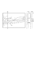
次に図3に基づいて、上述の断層画像取得装置102により取得され画像処理装置101により層構造が特定される網膜の断層画像の例を説明する。 Next, an example of a tomographic image of the retina acquired by the above-described tomographic image acquisition apparatus 102 and whose layer structure is specified by the image processing apparatus 101 will be described with reference to FIG.
次に、本実施例に係る層構造を同定する処理の適用対象である網膜層の構造について図3を用いて説明する。図3(a)は網膜の黄斑部の断層像を模式図として示したものであり実線で層境界の位置が示されている。黄斑部の二次元断層像(B−Scan画像、以下、断層像と呼ぶ)T1〜Tnの夫々はA−Scanを網膜表面の1ラインで行い二次元画像として構成したものである。A−Scanは連続して行うわけではなく、1ライン上にて所定の間隔で行われるため、隣り合うA−Scanの間は所定の補間方法により補間して二次元画像が構成される。 Next, the structure of the retinal layer to which the process for identifying the layer structure according to the present embodiment is applied will be described with reference to FIG. FIG. 3A shows a tomogram of the macular portion of the retina as a schematic diagram, and the position of the layer boundary is indicated by a solid line. Each of the two-dimensional tomographic images (B-Scan image, hereinafter referred to as tomographic images) T1 to Tn of the macular portion is formed as a two-dimensional image by performing A-Scan on one line of the retina surface. Since A-Scan is not performed continuously but at a predetermined interval on one line, a two-dimensional image is constructed by interpolating between adjacent A-Scans using a predetermined interpolation method.
断層像Tnにおいて、内境界膜(ILM:Inner Limiting Membrane)の界面L1、神経線維層(NFL:Nerve Fiber Layer)とその下部層との境界L2、神経線維層L2’が示されている。また内網状層とその下部の層との境界L3、外網状層をその下部の層との境界L4が示される。また、視細胞内節外節接合部(IS/OS:Interface between inner and outer segments of the photoreceptors)の境界L5、網膜色素上皮(RPE)の下側の境界L6が示されている。このように、網膜は深さ方向に複数の層が積層された層構造を有している。 In the tomographic image Tn, the interface L1 of the inner limiting membrane (ILM), the boundary L2 between the nerve fiber layer (NFL) and its lower layer, and the nerve fiber layer L2 'are shown. In addition, a boundary L3 between the inner mesh layer and the lower layer is shown, and a boundary L4 between the outer mesh layer and the lower layer is shown. In addition, a boundary L5 of an inner / outer segment of the photoreceptor cell (IS / OS) and a lower boundary L6 of the retinal pigment epithelium (RPE) are shown. Thus, the retina has a layer structure in which a plurality of layers are stacked in the depth direction.
なお、OCT撮像装置の性能によっては、IS/OSとRPEの境界が区別不可となる場合があるが、本発明においてはその精度は問題にしないこととする。また、内境界膜(ILM)や視細胞内節/外節接合部(IS/OS)は実際には所定の厚みを持つ層であるが、ごく薄い層であるため画像上では線で表示されている。そのため、画像の解像度がある程度低い状態では、例えば内境界膜の界面と内境界膜自体が画像上区別不可能となる。そのため、内境界膜の界面を特定することは内境界膜自体を特定することと実質的に同義となる。また、層境界と界面とは実質的に同義として用いる。 Depending on the performance of the OCT imaging apparatus, the boundary between IS / OS and RPE may be indistinguishable. However, in the present invention, the accuracy is not a problem. In addition, the inner boundary membrane (ILM) and the photoreceptor inner / outer segment junction (IS / OS) are actually layers having a predetermined thickness, but are very thin layers and are therefore displayed as lines on the image. ing. Therefore, when the image resolution is low to some extent, for example, the interface between the inner boundary film and the inner boundary film itself cannot be distinguished on the image. Therefore, specifying the interface of the inner boundary film is substantially synonymous with specifying the inner boundary film itself. Moreover, a layer boundary and an interface are used substantially synonymously.
一般に網膜はこのように複数の層が積層された層構造を有しているが、部位や病変によってはこれと異なる構造を取り得る。図3(b)も同じく網膜の黄斑部の断層画像である。ここでは、血管V1が存在しており、血管内の赤血球により信号光が減衰するため、血管V1のある水平方向の領域S2において、血管下の領域が画像化されず、偽像が発生してしまう。そのため、血管の存在しない領域S1と比較して、断層画像により特定される見かけ上の構造が異なっている。なお血管に限らず、白斑によっても白斑下の領域に偽像が発生することがある。 In general, the retina has a layered structure in which a plurality of layers are stacked in this way, but may have a different structure depending on a part or a lesion. FIG. 3B is also a tomographic image of the macular portion of the retina. Here, since the blood vessel V1 exists and the signal light is attenuated by the red blood cells in the blood vessel, the region under the blood vessel is not imaged in the horizontal region S2 where the blood vessel V1 exists, and a false image is generated. End up. Therefore, the apparent structure specified by the tomographic image is different from that in the region S1 where no blood vessel exists. Not only blood vessels but also vitiligo may cause false images in the area below the vitiligo.
これら病変等の異常や構造の変化が大きいのは現れるのは内境界膜L1から網膜色素上皮の境界L6までの間の層であるため、これらの層を特定した後、その内部の層を特定することとなる。 Since abnormalities such as lesions and structural changes appear in the layer between the inner boundary membrane L1 and the boundary L6 of the retinal pigment epithelium, after identifying these layers, the inner layers are identified. Will be.
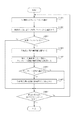
図4に示したフローチャートに従い上述の構成を有する画像処理装置101の処理の流れを説明する。本実施例における処理では、内境界膜の界面及び視細胞内節外節接合部の界面を特定する。なお、内境界膜または視細胞内節外節接合部についての界面とは、これら層と他の層との境界を指す。本実施例では下側から上側へのエッジを見ているため、深さ方向から見て上側の界面の位置を特定する処理である。画像の解像度によってはこれら層の幅が画像の1画素よりも狭い場合もありうる。この場合には、層境界として特定される位置が上側の界面、下側の界面、または層そのものの位置とが画像上では区別がつかなくなる場合があり、そのような場合には層の界面を特定することと層自体を特定することは同義である。 A processing flow of the image processing apparatus 101 having the above-described configuration will be described with reference to the flowchart shown in FIG. In the processing in this embodiment, the interface of the inner boundary membrane and the interface of the photoreceptor inner / outer joint junction are specified. It should be noted that the interface for the inner boundary membrane or the photoreceptor inner / outer joint junction refers to the boundary between these layers and other layers. In the present embodiment, since the edge from the lower side to the upper side is seen, this is a process of specifying the position of the upper interface as seen from the depth direction. Depending on the resolution of the image, the width of these layers may be narrower than one pixel of the image. In this case, the position specified as the layer boundary may be indistinguishable on the image from the upper interface, the lower interface, or the position of the layer itself. Specifying and specifying the layer itself are synonymous.
(ステップS401)
ステップS401において、画像取得部103は断層画像取得装置102で撮像したOCT断層画像を取得する。
(Step S401)
In step S <b> 401, the
(ステップS402)
ステップS402において、画像変換部104は画像取得部103で取得したOCT断層像に対して画像変換を行う。
(Step S402)
In step S <b> 402, the image conversion unit 104 performs image conversion on the OCT tomographic image acquired by the
本実施形態では断層像に対して、メディアンフィルタ(以後、メディアンフィルタで変換した画像をメディアン画像とする)と、2種類のSobelフィルタを適用した。この2種類のSobelフィルタとは、A−scanラインの深度方向に対して、輝度値の低い画素から高い画素へのエッジを強調するSobelフィルタと、輝度値の高い画素から低い画素へのエッジを強調するSobelフィルタである。以後これらのフィルタで変換した画像を順にSobel画像A、Sobel画像Bとする。 In the present embodiment, a median filter (hereinafter, an image converted by the median filter is referred to as a median image) and two types of Sobel filters are applied to the tomographic image. These two types of Sobel filters are a Sobel filter that emphasizes an edge from a pixel with a low luminance value to a high pixel and an edge from a pixel with a high luminance value to a low pixel in the depth direction of the A-scan line. This is a Sobel filter to be emphasized. Hereinafter, images converted by these filters are referred to as a Sobel image A and a Sobel image B in order.
図5にOCT断層像に対して2種類のSobelフィルタを適用した例を示す。図5(a)はSobel画像Aの例であり、特に、内境界膜と視細胞内節外節接合部のエッジが強調された画像になる。また、図5(b)はSobel画像Bの例であり、特に、神経線維層境界、内網状層、外網状層、網膜色素上皮が強調された画像になる。本ステップでは画像変換により、メディアン画像、Sobel画像A、Sobel画像Bを作成し、データサーバ113に保存する。 FIG. 5 shows an example in which two types of Sobel filters are applied to an OCT tomogram. FIG. 5A is an example of the Sobel image A, and in particular, an image in which the edge of the inner boundary membrane and the joint between the inner and outer segments of the photoreceptor cell is emphasized. FIG. 5B is an example of the Sobel image B, in particular, an image in which the nerve fiber layer boundary, the inner mesh layer, the outer mesh layer, and the retinal pigment epithelium are emphasized. In this step, a median image, a Sobel image A, and a Sobel image B are created by image conversion and stored in the data server 113.
但し、画像変換の方法はこれに限定されるものではなく、例えばメディアンフィルタの代わりに平均値フィルタのような平滑化フィルタを用いてもよい。さらに、本実施形態のような、平滑化フィルタやエッジ強調フィルタの他に、ガンマ補正のような階調変換フィルタやモルフォロジーフィルタなどを用いて画像変換を行ってもよい。また、画像変換を行わず、原画像輝度値のまま、次ステップの入力としてもよい。 However, the image conversion method is not limited to this. For example, a smoothing filter such as an average value filter may be used instead of the median filter. Furthermore, in addition to the smoothing filter and the edge enhancement filter as in the present embodiment, image conversion may be performed using a gradation conversion filter such as gamma correction, a morphological filter, or the like. Alternatively, the image conversion may not be performed, and the input of the next step may be performed with the original image luminance value unchanged.
(ステップS403)
ステップS403において、輝度情報生成部105はステップS402で変換した画像から輝度情報を生成する。
(Step S403)
In step S403, the luminance
本実施形態では、所定位置の画像領域で深度方向に、1画素単位で輝度値を調べ、輝度情報としてプロファイルを作成する。所定位置はAスキャンラインすなわち深さ方向に並んだ一次元の画像領域とする。A−Scanラインとは画像における深さ方向の画素の列を指す。プロファイル画像の深さ方向はOCTにおける軸方向のスキャン(Aスキャン)の方向と一致する。必ずしもAスキャンが行われた位置に対応する画素列でなくてもよい。本実施形態では幅256pixel、高さ250pixelの断層像に対して、幅5pixel間隔でA−scanラインを走査するため、一枚のBスキャン画像に対して50本のA−scanラインを網膜層境界の特定対象とする。これらの各A−scanラインでプロファイルが生成される。これを、前ステップから入力された変換画像についてそれぞれ行い、データサーバ113に保存する。記憶部111に保存してもよい。 In the present embodiment, a luminance value is examined in units of one pixel in the depth direction in an image region at a predetermined position, and a profile is created as luminance information. The predetermined position is an A scan line, that is, a one-dimensional image region arranged in the depth direction. The A-Scan line refers to a row of pixels in the depth direction in the image. The depth direction of the profile image coincides with the axial scan (A scan) direction in OCT. It does not necessarily have to be a pixel column corresponding to the position where the A scan was performed. In the present embodiment, since the A-scan line is scanned at a width of 5 pixels with respect to a tomographic image having a width of 256 pixels and a height of 250 pixels, 50 A-scan lines are used for one B-scan image. The specific target. A profile is generated for each of these A-scan lines. This is performed for each of the converted images input from the previous step and stored in the data server 113. You may preserve | save in the memory | storage part 111. FIG.
但し、輝度情報の作成方法はこれに限定されるものではなく、例えば1画素単位ではなく、複数の画素からなるブロック領域を用いて作成してもよい。 さらに、A−Scanラインを走査する間隔もこれに限定されるものではない。 However, the method of creating the luminance information is not limited to this, and for example, the luminance information may be created using a block region including a plurality of pixels instead of one pixel. Further, the interval for scanning the A-Scan line is not limited to this.
(ステップS404)
ステップS404において、検出部106はステップS403で作成した輝度情報から特徴領域を取得する。
(Step S404)
In step S404, the
本実施例では、Sobel画像Aから作成されたプロファイルを調べ、そのうち所定の閾値以上である領域を特徴領域として取得する。Sobel画像は画像のエッジを強調する画像であり、深さ方向の輝度変化が所定の閾値以上となっている領域を意味する。以下、この領域をピーク領域またはピークと称する。 In this embodiment, the profile created from the Sobel image A is examined, and an area that is equal to or greater than a predetermined threshold is acquired as a feature area. The Sobel image is an image that emphasizes the edge of the image, and means a region in which the luminance change in the depth direction is equal to or greater than a predetermined threshold. Hereinafter, this region is referred to as a peak region or a peak.
ある断層像からピークを検出する例を、図6を用いて説明する。図6のOCT断層画像で、A6は断層画像中の一つのA−scanライン(画素列)を表す。 An example of detecting a peak from a certain tomographic image will be described with reference to FIG. In the OCT tomographic image of FIG. 6, A6 represents one A-scan line (pixel row) in the tomographic image.
PSA6はA−scanラインA6のSobel画像Aのプロファイル、PSB6はA−scanラインA6のSobel画像Bのプロファイルを表す。ステップS302で説明したとおり、Sobel画像A、Bのプロファイルは特定の網膜層境界が強調され、輝度変化のグラフにおいてピークとして現れる。本実施形態では、閾値Thを設定し、この閾値以上の領域の領域だけをピークとみなす。この閾値が本発明における所定の閾値または第一の閾値に相当する。このようにピークをA−Scanライン毎に検出し、それぞれのピークの位置、大きさをデータサーバ113に保存する。ここでピークの位置及び大きさとは、ピーク領域における極大点の位置及び大きさとする。このピークの極大となる点を特徴点とする。本実施例では、検出部106がこのピークの位置を層境界の位置として取得する。この段階では、位置が特定された層境界がどの種類であるかは特定されていない。
PSA6 represents the profile of the Sobel image A on the A-scan line A6, and PSB6 represents the profile of the Sobel image B on the A-scan line A6. As described in step S302, the profiles of the Sobel images A and B appear as peaks in the graph of the luminance change with the specific retinal layer boundary emphasized. In the present embodiment, a threshold value Th is set, and only a region having a region equal to or greater than the threshold value is regarded as a peak. This threshold corresponds to the predetermined threshold or the first threshold in the present invention. In this way, the peak is detected for each A-Scan line, and the position and size of each peak are stored in the data server 113. Here, the peak position and size are the position and size of the maximum point in the peak region. The point at which this peak is maximum is defined as a feature point. In this embodiment, the
なお、特徴領域の検出方法はこれに限定されるものではない。また、特徴点も極大値のみでなく、例えばプロファイルの最大点や最小点など、特徴領域内の点を採用してよい。 The feature region detection method is not limited to this. Further, the feature points are not limited to the local maximum values, but may be points in the feature region such as the maximum point and the minimum point of the profile.
以下、ステップS405及びS406において、検出部106の検出した層境界またはエッジに基づいて構造判定部1071が構造を判定する処理を行う。本実施例では、各Aスキャンラインにおいて存在する層境界の種類を決定する。
Hereinafter, in steps S405 and S406, the structure determination unit 1071 performs a process of determining the structure based on the layer boundary or edge detected by the
(ステップS405)
ステップS405において、テンプレート選択部107では、ステップS404で検出した特徴点からおおよその網膜層構造を把握する。そして、その層構造に応じてテンプレートを選択する。これにより、検出部106が取得した位置の層境界のいずれかが対応する層境界の種類が決定することとなる。そして、層境界特定部108はステップS404にて取得した位置とテンプレート情報とを用いて、層境界の種類との対応関係を特定する。
(Step S405)
In step S405, the
本ステップの詳しい処理は図7のフローチャートを用いて説明する。図7のフローチャートではA−scanライン単位で処理する。全てのA−scanラインで、図7のフローチャートの処理を終えたら、ステップS406へ進む。 Detailed processing of this step will be described with reference to the flowchart of FIG. In the flowchart of FIG. 7, processing is performed in units of A-scan lines. When the process of the flowchart of FIG. 7 is completed for all A-scan lines, the process proceeds to step S406.
(ステップS406)
ステップS406において、層境界補間部109では、網膜層境界が特定されていないA−scanラインにおいて、網膜層境界を補間する。
(Step S406)
In step S406, the layer
本ステップの詳しい処理は図8のフローチャートを用いて説明する。図8のフローチャートではA−scanライン単位で分岐しながら処理されていく。全てのA−scanラインで、図8のフローチャートの処理を終えたら、ステップS407へ進む。 Detailed processing of this step will be described with reference to the flowchart of FIG. In the flowchart of FIG. 8, processing is performed while branching in units of A-scan lines. When the processing of the flowchart of FIG. 8 is completed for all A-scan lines, the process proceeds to step S407.
(ステップS407)
ステップS407において、所定間隔のA−scanライン毎に特定した内境界膜または視細胞内節外節接合部の境界点をつなぎ合わせ、表示制御部110が表示部112に表示させる。
(Step S407)
In step S407, the boundary points of the inner boundary membrane or the photoreceptor cell inner / outer node junction specified for each A-scan line at a predetermined interval are connected together, and the
このように、画像上の特徴から特定すべき層境界の種類を決定することにより、層境界の種類を特定する誤りを減らすことができる。また、テンプレートを選択して適用し、層境界を特定することにより、画像上の特徴に合わせて層境界の位置を特定することができるため、層境界の位置の精度または信頼性を向上させることができる。
次に図8に従い、上述のステップS405においてテンプレート選択部107及び層境界特定部108が実行する処理の流れを説明する。
As described above, by determining the type of the layer boundary to be specified from the feature on the image, it is possible to reduce errors specifying the type of the layer boundary. In addition, by selecting and applying a template and specifying the layer boundary, the position of the layer boundary can be specified according to the feature on the image, so that the accuracy or reliability of the position of the layer boundary is improved. Can do.
Next, the flow of processing executed by the
(ステップS701)
ステップS701において、テンプレート選択部107は解析の対象とする画素列(Aスキャンライン)を選択する。この画素列は、水平方向に対して5画素間隔で深さ方向に並ぶ画素列を順に選択していく。なおこれに限らず間隔は任意に設定してよい。
(Step S701)
In step S701, the
(ステップS702)
ステップS702において、テンプレート選択部107では、A−scanライン毎に特徴点を数え、特定対象とする層境界の種類を決定する。特徴点の数が二つである場合には、内境界膜の界面と視細胞内接外節接合部の界面を特定すべき層境界として決定し、ステップS703に進む。特徴点の数が二つでない場合にはステップS705へと進む。
(Step S702)
In step S702, the
具体的な処理は図8を用いて説明する。図8は網膜の断層画像であり、A81とA82は断層像中のA−scanラインを表す。PSA81とPSA82はSobel画像Aから求めたプロファイルを表す。網膜層を把握するために、プロファイル中のピークを数える。図8に示された断層画像では、血管V1による偽像が発生し視細胞内節外節接合部が画像中に現れないA−scanラインが存在している。そのため、A−scan ライン毎にSobel画像Aのプロファイル中のピークを数え、ピークが二つ存在するとき、そのA−scanラインには内境界膜及び視細胞内節外節接合部が画像中に存在する可能性が高いと判定する。特定対象の層境界の種類は内境界膜及び視細胞内節外節接合部と決定する。その後、ステップS702へ進む。ピークが一つ存在するとき、そのA−scanラインには内境界膜だけが画像中に存在する可能性が高いと判定し、特定対象の層境界の種類は内境界膜と決定する。ステップS303へ進む。ピークが二つでも一つでもないとき、ノイズが存在する可能性が高い判定し、特定対象の層境界の種類はなしと決定する。そのA−scanラインでは網膜層境界を特定しない。 Specific processing will be described with reference to FIG. FIG. 8 is a tomographic image of the retina, and A81 and A82 represent A-scan lines in the tomographic image. PSA 81 and PSA 82 represent profiles obtained from the Sobel image A. To understand the retinal layer, count the peaks in the profile. In the tomographic image shown in FIG. 8, there is an A-scan line in which a false image is generated by the blood vessel V <b> 1 and the photoreceptor inner / outer node joint does not appear in the image. Therefore, the peak in the profile of the Sobel image A is counted for each A-scan line, and when there are two peaks, the inner boundary membrane and the photoreceptor inner / outer joint junction are included in the A-scan line. It is determined that there is a high possibility that it exists. The type of the layer boundary of the specific object is determined as the inner boundary membrane and the photoreceptor inner / outer joint junction. Thereafter, the process proceeds to step S702. When one peak exists, it is determined that there is a high possibility that only the inner boundary film exists in the image in the A-scan line, and the type of the layer boundary of the specific target is determined as the inner boundary film. Proceed to step S303. When the number of peaks is neither two nor one, it is determined that there is a high possibility of noise, and it is determined that there is no type of layer boundary to be specified. The A-scan line does not specify the retinal layer boundary.
(ステップS703)
ステップS703において、テンプレート選択部107は特徴点すなわちエッジとして検出される層境界の数に応じたテンプレートを記憶部111から選択する。
(Step S703)
In step S703, the
(ステップS704)
層境界特定部108では、ステップS702において、内境界膜・視細胞内節外節接合部が存在する可能性が高いと判定されたA−scanラインに対して各層境界の特定を行う。ここで、テンプレート情報を用いて二つの特徴点の位置を浅い方から順に内境界膜の界面、視細胞内節外節接合部の界面として特定する。
(Step S704)
In step S702, the layer
なお以下のような処理をすることも可能である。具体的な処理は図9を用いて説明する。図9は網膜の断層像であり、A9は断層像中の一つのA−scanラインを表す。PSA9はSobel画像Aから求めたプロファイル(以後、プロファイルPSA9とする)、PMD9はメディアン画像から求めたプロファイル(以後、プロファイルPMD9)である。また、本ステップでは内境界膜・視細胞内節外節接合部の二層の境界を特定するため、メディアン画像から求めたプロファイルの参照用プロファイルPRE9(以後、プロファイルPRE9)を用意する。プロファイルPRE9は内境界膜・視細胞内節外節接合部の二層が存在するA−scanラインのプロファイルの典型例である。ここで典型例とは、ノイズが存在せず、且つ、内境界膜・視細胞内節外節接合部の二層が存在するA−scanラインにおける、各層の輝度の傾向を示したものである。例えば、内境界膜と視細胞内節外節接合部の間の輝度値を見たとき、神経線維層や内網状層が存在するために、内境界膜寄りの方が輝度値が高い傾向にある。そのような輝度の特徴を示すプロファイルPRE9を作成しておく。なお、このプロファイルPRE9は各網膜層の輝度の傾向と位置関係が参照できればよく、部位によって変化する各網膜層の厚さには対応させないため、内境界膜・視細胞内節外節接合部の二層が存在するA−scanラインであればどこでも使用することができる。これを用いて、二つのピークが内境界膜・視細胞内節外節接合部に当てはまるか否かを判定する。 The following processing can also be performed. Specific processing will be described with reference to FIG. FIG. 9 is a tomographic image of the retina, and A9 represents one A-scan line in the tomographic image. PSA9 is a profile obtained from the Sobel image A (hereinafter referred to as profile PSA9), and PMD9 is a profile obtained from the median image (hereinafter referred to as profile PMD9). Also, in this step, a reference profile PRE9 (hereinafter referred to as profile PRE9) of the profile obtained from the median image is prepared in order to specify the boundary between the two layers of the inner boundary membrane and the photoreceptor inner / outer joint junction. The profile PRE9 is a typical example of the profile of the A-scan line in which two layers of the inner boundary membrane and the photoreceptor inner / outer node junction exist. Here, the typical example shows the tendency of the brightness of each layer in the A-scan line where there is no noise and there are two layers of the inner boundary membrane / photocell inner / outer joint junction. . For example, when looking at the luminance value between the inner boundary membrane and the photoreceptor inner / outer node junction, there is a nerve fiber layer and inner plexiform layer, and the luminance value tends to be higher near the inner boundary membrane. is there. A profile PRE9 showing such luminance characteristics is created in advance. The profile PRE9 only needs to refer to the luminance trend and positional relationship of each retinal layer, and does not correspond to the thickness of each retinal layer that changes depending on the region. Any A-scan line with two layers can be used. Using this, it is determined whether or not the two peaks apply to the inner boundary membrane / photocell inner / outer joint junction.
まず、プロファイルPSA9における各ピーク間の平均輝度値を算出する。輝度値はプロファイルPSA9の位置に対応したプロファイルPMD9の値を用いる。プロファイルPSA10における2つのピークを、浅い位置から第一ピーク、第二ピークとする。平均輝度値を算出する範囲は、第一ピークと第二ピーク間(以後、ピーク間A1とする)、第一ピークと第二ピークの間を二等分し、第一ピークに近い方の範囲(以後、ピーク間A11とする)と第二ピークに近い方の範囲(以後、ピーク間A12とする)である。また、背景(画像中の網膜層以外の領域)の平均輝度値も算出する。本実施形態ではメディアン画像に対して経験的に決定した閾値を用いて二値化し、閾値以下の領域だけを対象にして平均輝度値を算出する。但し、背景の平均輝度値の算出方法はこれに限定されるものではなく、二値化における閾値の決定を判別分析法やP−tile法などを用いて決定してもよい。また、網膜層の存在しない画像の上端や下端の輝度値を用いて平均輝度値を算出してもよい。 First, an average luminance value between the peaks in the profile PSA9 is calculated. As the luminance value, the value of the profile PMD9 corresponding to the position of the profile PSA9 is used. Two peaks in profile PSA10 are defined as a first peak and a second peak from a shallow position. The range for calculating the average luminance value is the range closer to the first peak between the first peak and the second peak (hereinafter referred to as peak-to-peak A1), the first peak and the second peak divided into two equal parts. (Hereinafter referred to as A11 between peaks) and the range closer to the second peak (hereinafter referred to as A12 between peaks). Also, the average luminance value of the background (region other than the retinal layer in the image) is calculated. In this embodiment, the median image is binarized using a threshold value determined empirically, and an average luminance value is calculated only for an area below the threshold value. However, the method of calculating the average luminance value of the background is not limited to this, and the threshold value in binarization may be determined using a discriminant analysis method, a P-tile method, or the like. Further, the average luminance value may be calculated using the luminance values at the upper end and the lower end of the image without the retinal layer.
次にプロファイルPRE9に習って、算出した平均輝度値の大小関係を比較する。プロファイルPRE9から、平均輝度値において、ピーク間A1>背景の平均輝度値、ピーク間A11>ピーク間A12という条件が導かれる。これらに算出した平均輝度値を当てはめて、内境界膜・視細胞内節外節接合部の二層の妥当性を確かめる。条件を全て満たしたとき、第一ピーク、第二ピークはそれぞれ内境界膜・視細胞内節外節接合部の境界として特定され、データサーバ113に保存される。条件を一つでも満たさないものがあったとき、そのA−scanラインでは網膜層境界を特定しない。 Next, the magnitude relationship of the calculated average luminance values is compared according to the profile PRE9. From the profile PRE9, in the average luminance value, the conditions of peak-to-peak A1> background average luminance value, peak-to-peak A11> peak-to-peak A12 are derived. By applying the calculated average luminance value to these, the validity of the two layers of the inner boundary membrane and the inner / outer joint junction of photoreceptor cells is confirmed. When all the conditions are satisfied, the first peak and the second peak are specified as the boundary between the inner boundary membrane and the photoreceptor inner / outer node junction, respectively, and stored in the data server 113. When there is something that does not satisfy even one condition, the retinal layer boundary is not specified in the A-scan line.
(ステップS705)
ステップS705において、テンプレート選択部107は、Aスキャンライン上のエッジの数が一つであるか否かを判定する。一つと判定された場合には、内境界膜の界面を特定すべき層境界として特定する。ステップS706に進む。0または3以上と判定された場合には、適切なテンプレートが存在しないとして、ステップS708に進む。このように、層境界が存在するとしても、適切なテンプレートが存在しないと判定される場合には、層境界の検出の誤りがある可能性が高いとして特定を行わない。これにより、Aスキャンライン全体の情報を用いて、当該Aスキャンラインにおける層構造の判定を行うため、ノイズや構造の変化に強い層構造の判定が実現されることとなる。
(Step S705)
In step S705, the
(ステップS706)
ステップS706において、テンプレート選択部107は、特徴点が一つの場合のテンプレートを選択して、記憶部111から取得する。
(Step S706)
In step S <b> 706, the
(ステップS707)
層境界特定部108は内境界膜だけが画像中に存在する可能性が高いと判定されたA−scanラインに対して各層境界の特定を行う。ここで、テンプレート情報を用いて一つの特徴点の位置を内境界膜の界面として特定する。
(Step S707)
The layer
なお以下のような処理をすることも可能である。具体的な処理は図10を用いて説明する。図10は網膜の断層像であり、A10は断層像中の一つのA−scanラインを表す。PSA10はSobel画像Aから求めたプロファイル(以後、プロファイルPSA10とする)、PMD10はメディアン画像から求めたプロファイル(以後、プロファイルPMD10)である。また、本ステップでは内境界膜の境界を特定するため、メディアン画像から求めたプロファイルの参照用プロファイルPRE10(以後、プロファイルPRE10)を用意する。この参照用プロファイルは内境界膜と、その下に偽像が存在するA−scanラインのプロファイルの典型例である。これを用いて、ピークが内境界膜に当てはまるか否かを判定する。 The following processing can also be performed. Specific processing will be described with reference to FIG. FIG. 10 is a tomographic image of the retina, and A10 represents one A-scan line in the tomographic image. PSA10 is a profile obtained from the Sobel image A (hereinafter referred to as profile PSA10), and PMD10 is a profile obtained from the median image (hereinafter referred to as profile PMD10). In this step, in order to specify the boundary of the inner boundary film, a profile for reference PRE10 (hereinafter, profile PRE10) obtained from the median image is prepared. This reference profile is a typical example of the profile of the A-scan line in which an inner boundary film and a false image exist below. This is used to determine whether the peak applies to the inner boundary membrane.
本ステップでは、プロファイルPSA10とプロファイルPMD10を用いて、ピーク前後の所定の範囲内における平均輝度値を算出する。具体的には、A−scanライン上で、ピークの前後10画素(以後、ピーク上B1、ピーク下B2とする)をそれぞれ算出範囲とする。 In this step, an average luminance value within a predetermined range before and after the peak is calculated using the profile PSA10 and the profile PMD10. More specifically, on the A-scan line, 10 pixels before and after the peak (hereinafter referred to as the upper peak B1 and the lower peak B2) are set as the calculation ranges, respectively.
次にプロファイルの典型例に習って、算出した平均輝度値の大小関係を比較する。PRE10から、平均輝度値において、ピーク上B1<ピーク下B2という条件が導かれる。これらを算出した平均輝度値を当てはめて、内境界膜の妥当性を確かめる。条件を満たしたとき、ピークは内境界膜の境界として特定され、データサーバ113に保存される。条件を満たさなかったとき、そのA−scanラインでは網膜層境界を特定しない。
Next, following the typical example of the profile, the magnitude relationship of the calculated average luminance values is compared. From the PRE 10, the condition that the upper peak B 1 <the
(ステップS708)
ステップS708にて、層境界特定部108が特定対象とする全てのAスキャンラインが選択されたか否かを判定する。テンプレートが存在するとしないとに関わらずステップS701にて選択されたか否かが判定の基準とする。網膜層境界の特定対象となっている全てのA−scanラインが図7のフローチャートの処理を終了したらステップS406へ進む。ステップS708にて未だ選択されていないAスキャンラインがあると判定された場合には、ステップS701の処理に進む。
(Step S708)
In step S708, the layer
このように、水平方向に対する所定の間隔でAスキャンラインに対して特徴点であるエッジの数に応じて特定すべき層境界の種類を決定するため、画像における構造や特徴の変化に対応して層境界の種類を特定することができる。また、特徴点の数に応じたテンプレート情報に基づいて層境界の位置及び種類を特定するため、画像における構造や特徴の変化に対応して層境界の種類及び位置を特定することができる。 In this way, the type of the layer boundary to be specified is determined according to the number of edges that are feature points with respect to the A scan line at a predetermined interval in the horizontal direction. The type of layer boundary can be specified. In addition, since the position and type of the layer boundary are specified based on the template information corresponding to the number of feature points, the type and position of the layer boundary can be specified in response to changes in the structure and features in the image.
次に層境界補間部109がステップS406にて行う処理の詳細について図11のフローチャートに従い説明する。この補間処理は層境界の種類毎に行われるものであり、例えば内境界膜の界面の補間処理として行われる。
Next, details of the process performed by the layer
(ステップS1101)
ステップS1101において、層境界補間部109では、層境界の位置の特定対象とするAスキャンラインを選択する。ここでは、先述のステップS405の処理において層境界の位置が特定されていないAスキャンラインが選択される。ここで、層境界の位置が特定されていないAスキャンラインとは、テンプレートが存在しなかったAスキャンラインである。
(Step S1101)
In step S <b> 1101, the layer
(ステップS1102)
層境界補間部109は、層境界を特定できていないA−scanラインを中心とした局所領域(以後、近傍領域とする)を考え、その領域内の特定されている網膜層境界の座標を基に補間する。具体的な説明は図12を用いて行う。図中のA12は網膜層境界が特定されていないA−scanラインであり、RはそのA−scanラインを中心とした近傍領域であり、近傍領域内に所定の本数のA−scanラインが含まれるように範囲を設定する。この近傍領域は、網膜層境界の特定対象となっているA−scanラインを中心に、周囲9×9本のA−scanラインが存在する範囲とする。ここで層境界補間部109が、特定対象とするAスキャンラインの近傍領域内に網膜層境界が特定されているA−scanラインが所定の数より下回ると判定した場合、補間処理を行ったとしてもその信頼性は低い。この場合ステップS1107へ進み、補間処理は行わない。所定の数を上回るA−scanラインが近傍領域内に存在する場合にのみ、ステップS1103へと進み、補間処理を行う。所定の数を下回ったA−Scanラインについては、ステップS1101乃至S1107を繰り返すことで、徐々に近傍領域内の網膜層境界が特定されてゆき、所定の数を上回った時点で補間処理が行われることとなる。本実施形態では、所定の数を近傍領域内に存在する、網膜層境界の特定対象となっているA−scanラインの半数、つまり40とする。
(Step S1102)
The layer
(ステップS1103)
ステップS1103において、層境界補間部109では、本ステップまでに網膜層境界を特定できていないA−scanラインについて、網膜層境界を特定するための特徴量を算出する。特徴量は本ステップまでに網膜層境界が特定されているA−scanラインの情報から算出される。
(Step S1103)
In step S1103, the layer
本実施例では、網膜層境界を特定できていないA−scanラインを中心とした局所領域(以後、近傍領域とする)を考え、その領域内の特定されている網膜層境界を基に基準位置を算出する。図12のような網膜層境界が特定されていないA−scanラインを中心とした近傍領域を考える。近傍領域内で特定されている各網膜層境界のz座標平均値を求めて基準位置とする。基準位置を算出するか否かの判定条件もステップS402と同様に、近傍領域内に網膜層境界が特定されているA−scanラインが所定の数より大きいか小さいかで行う。基準位置を算出したら、層境界補間部109では、で算出した各層の基準位置を用いて層境界が存在すると考えられる画像領域を探索範囲として決定する。この探索範囲内においてA−scanラインの網膜層境界を特定する。基準位置として算出した各網膜層のz座標平均値を用いて、その座標値の前後、所定の深さ方向の範囲内を網膜層境界の探索範囲とする。本実施形態では、所定の範囲はz座標平均値の上下5画素とする。
In this embodiment, a local region centered on an A-scan line where the retinal layer boundary cannot be specified (hereinafter referred to as a neighboring region) is considered, and the reference position is based on the specified retinal layer boundary in the region. Is calculated. Consider a neighboring region centered on an A-scan line in which the retinal layer boundary is not specified as shown in FIG. An average z-coordinate value of each retinal layer boundary specified in the vicinity region is obtained as a reference position. Whether or not to calculate the reference position is determined according to whether or not the number of A-scan lines in which the retinal layer boundary is specified in the vicinity region is larger or smaller than the predetermined number, as in step S402. When the reference position is calculated, the layer
なお、これに限らず探索範囲の設定は種々の形態を取ることができる。例えば、画像のノイズが少ない場合には探索範囲を大きく取ることでより正確に層境界の特定を行うことができる。また、層構造が比較的単調で平坦な場合には、探索範囲をそれほど大きく取る必要がないため、周囲の層構造の情報を用いて探索範囲を変えてもよい。 Note that the search range is not limited to this, and can take various forms. For example, when there is little noise in the image, the layer boundary can be specified more accurately by increasing the search range. Further, when the layer structure is relatively monotonous and flat, the search range does not need to be so large, and the search range may be changed using information on the surrounding layer structure.
更には、ノイズの等方性などを利用して画像全体または処理対象のAスキャンラインからノイズ成分を抽出し、局所的にノイズと信号成分を分離してもよい。 Furthermore, the noise component may be extracted locally from the entire image or the A scan line to be processed using the isotropy of noise, and the noise and signal component may be separated locally.
(ステップS1104)
S1104にて、層境界補間部109は探索範囲内でSobel画像Aのプロファイルにおけるピーク領域を探索する。ピーク領域とは、Sobel画像Aのプロファイルにおける所定以上大きい極大値の付近の領域である。これは断層画像において輝度変化が所定の閾値を超える領域に対応する。この所定の閾値が本発明における第二の閾値に相当する。
(Step S1104)
In S1104, the layer
探索範囲を限り、その中でピークを探すこととなるため、ステップS404にて検出部106が設定した第一の閾値よりも小さな閾値で小さなピーク領域を見つけることができる。また、近傍領域において特定済みの層境界の深さ方向の位置の平均値に基づいて探索範囲を設定するため、層境界が存在する確率の高い領域を設定することができる。
Since the search range is limited and a peak is searched for in the search range, a small peak region can be found with a threshold smaller than the first threshold set by the
(ステップS1105)
層境界補間部109は、ピーク領域が存在するか否かを判定する。存在すると判定した場合には、補間対象となる層境界の存在位置が特定できると考えられるためステップS1106に進み補間処理を続行する。存在しないと判定した場合には、補間処理の信頼性が低くなると考えられるため、補間処理を行わずステップS1107へと進む。
(Step S1105)
The layer
なお、ステップS1105においてピーク領域が存在しないとき、その探索範囲内のSobel画像Aのエッジ成分が一番大きな位置を網膜層境界と特定してもよい。 When no peak region exists in step S1105, the position where the edge component of the Sobel image A within the search range is the largest may be specified as the retinal layer boundary.
(ステップS1106)
層境界補間部109は、ピーク領域のうち、最も輝度変化が大きい位置を境界の位置として特定する。
(Step S1106)
The layer
(ステップS1107)
層境界補間部109は、特定対象となる全Aスキャンラインにおいて層境界が特定されたか否かを判定し、未特定のAスキャンラインがある場合にはステップS1101に進み、補間処理が行われる。全Aスキャンラインにおいて層境界が特定された場合には、処理を終了する。なお、処理時間やループの回数によって処理を打ち切ってもよい。また、S1101からS1107のループを所定回数繰り返しても特定済みのAスキャンラインの数が変わらない場合には処理を打ち切るとしてもよい。
(Step S1107)
The layer
このように、特定済みの層境界の深さ方向の位置に基づいて探索範囲を定め、この探索範囲内の輝度変化に基づいて層境界の位置を特定する。これによりAスキャンライン全体における輝度変化に基づいて層境界を特定する場合に比べて精度を向上させることができる。また、探索範囲内を限ることにより、ピークを探索する際の閾値をより小さくすることができるため、より小さな輝度変化から層境界の位置を特定することができる。 Thus, the search range is determined based on the position of the specified layer boundary in the depth direction, and the position of the layer boundary is specified based on the luminance change within the search range. Thereby, the accuracy can be improved as compared with the case where the layer boundary is specified based on the luminance change in the entire A scan line. Further, by limiting the search range, the threshold for searching for a peak can be made smaller, so that the position of the layer boundary can be specified from a smaller luminance change.
以上、本実施例では、被検眼の断層像中の網膜層境界を特定する処理において、近傍領域における各網膜層の輝度値や境界の位置を算出し、その情報に基づいた網膜層境界の特定条件を設定する。これにより、網膜層の輝度値や層構造が変化しても間違えることなく網膜層境界を特定することができる。例えば、OCTでは同一の網膜層であっても、部位によってプロファイルが大きく変化する。そのような輝度値の変化が起きても、近傍領域から各網膜層の情報を使うことで、特定対象となっている部位に適した網膜層境界の特定条件を設定することができ、精度よく網膜層境界を特定することができる。また、個人差や機種による輝度値の傾向の違いについても、手作業による閾値の調整を行わずに、入力された画像から、適切な網膜層境界の特定条件を設定することができる。よって、眼部を撮影した光干渉断層画像において、異なる複数の構造が現れる場合であっても、層境界の種類を特定する際の誤りを減らすことができる。 As described above, in the present embodiment, in the process of identifying the retinal layer boundary in the tomographic image of the eye to be examined, the luminance value and boundary position of each retinal layer in the vicinity region are calculated, and the retinal layer boundary is identified based on the information. Set conditions. Thereby, even if the luminance value or the layer structure of the retinal layer changes, the retinal layer boundary can be specified without making a mistake. For example, in OCT, even if the retinal layer is the same, the profile varies greatly depending on the site. Even if such a change in luminance value occurs, using the information of each retinal layer from the neighboring area, it is possible to set a specific condition for the retinal layer boundary suitable for the part to be specified, with high accuracy. Retinal layer boundaries can be identified. In addition, with regard to differences in brightness values depending on individual differences and models, appropriate retinal layer boundary specifying conditions can be set from an input image without manually adjusting the threshold value. Therefore, even when a plurality of different structures appear in the optical coherence tomographic image obtained by photographing the eye, errors in specifying the type of layer boundary can be reduced.
実施例2では、本発明を神経線維層の界面、内網状層の界面、外網状層の界面の特定に適用した例である。また、本実施例ではテンプレート情報の選択後に、画像のプロファイルとテンプレート情報とが適合するか否かを判定する。この判定部はテンプレート選択部が兼ねるが、判定部として機能する回路を別途設けてもよい。 In Example 2, the present invention is applied to the specification of the interface of the nerve fiber layer, the interface of the inner mesh layer, and the interface of the outer mesh layer. In this embodiment, after the template information is selected, it is determined whether or not the profile of the image matches the template information. This determination unit also serves as a template selection unit, but a circuit that functions as a determination unit may be provided separately.
ここで、内境界膜の界面と視細胞内節外節接合部の界面は予め特定されているものとする。神経線維層・内網状層・外網状層の構造に応じた参照用プロファイルをそれぞれ用意し、Sobel画像Bのプロファイルから求めた特徴点の数によって、参照用プロファイルを切り換えることで各網膜層境界を特定する。 Here, it is assumed that the interface between the inner boundary membrane and the interface between the photoreceptor inner and outer joints is specified in advance. Prepare a reference profile according to the structure of the nerve fiber layer, inner plexiform layer, and outer reticular layer, and switch the reference profile according to the number of feature points obtained from the profile of Sobel image B. Identify.
本実施例では、選択されたテンプレートが適切か否かを判定する際に、輝度変化のピーク位置の上下の領域の輝度値を用いる。網膜の各層毎の反射率が違うため、この層領域の輝度値を用いることにより、より層境界及び層の種類の特定を正確に行うことが可能である。 In this embodiment, when determining whether or not the selected template is appropriate, the luminance values of the regions above and below the peak position of the luminance change are used. Since the reflectance of each layer of the retina is different, it is possible to more accurately identify the layer boundary and the layer type by using the luminance value of this layer region.
画像処理システムの構成については実施例1と同様であるため説明を省略する。 Since the configuration of the image processing system is the same as that of the first embodiment, description thereof is omitted.
図13に記載のフローチャートに従い、画像処理装置101が実行する処理の流れを説明する。なお、実施例1における処理と同様の部分については説明を省略する。 The flow of processing executed by the image processing apparatus 101 will be described with reference to the flowchart shown in FIG. Note that a description of the same parts as the processing in the first embodiment will be omitted.
(ステップS1304)
ステップS1304では、内境界膜の界面と、視細胞内節外節接合部の界面とを特定する。この処理は、実施例1のように特定しても、その他の方法で特定してもよい。例えば、これら層境界の位置が予め特定されている断層画像を取得して、その特定された位置データを用いてもよい。この内境界膜の界面と視細胞内節外節接合部の界面の位置を利用して、神経線維層の界面、内網状層の界面、及び外網状層の界面を特定する。
(Step S1304)
In step S1304, the interface of the inner boundary membrane and the interface of the photoreceptor inner / outer joint junction are specified. This process may be specified as in the first embodiment or may be specified by other methods. For example, a tomographic image in which the position of the layer boundary is specified in advance may be acquired and the specified position data may be used. Using the position of the interface between the inner boundary membrane and the interface between the inner and outer segments of the photoreceptor cell, the interface of the nerve fiber layer, the interface of the inner mesh layer, and the interface of the outer mesh layer are specified.
(ステップS1306)
ステップS1306では、テンプレート選択部107がテンプレート情報を選択し、層境界特定部108が層境界を特定する処理を行う。詳細は後述するが、テンプレートの選択処理の後に、選択されたテンプレート情報と断層画像のプロファイルとが適合するか否かを判定する処理を行う点が実施例1と異なっている。
(Step S1306)
In step S1306, the
(ステップS1307)
ステップS1307では、ステップS1306で特定できなかった層境界の位置を補間する処理を行う。詳細は後述するが、探索範囲内で発見されたピーク領域のうち、算出された平均Z座標に最も近いピーク領域のピーク位置を層境界の位置として特定する点が実施例1と異なっている。
(Step S1307)
In step S1307, a process of interpolating the position of the layer boundary that could not be specified in step S1306 is performed. Although details will be described later, it is different from the first embodiment in that the peak position of the peak area closest to the calculated average Z coordinate among the peak areas found within the search range is specified as the position of the layer boundary.
上述のステップS1306にてテンプレート選択部107及び層境界特定部108が行う処理の流れを図14のフローチャートに従い説明する。なお、実施例1の処理と共通する部分については説明を省略する。
The flow of processing performed by the
(ステップS1402)
ステップS1402の処理は、実施例1のステップS702、S703、S705、S706の処理をまとめて表現したものである。具体的な処理は図15を用いて説明する。図15は網膜の断層像であり、A151とA152は断層像中のA−scanラインを表す。PSB151とPSB152はSobel画像Bから求めたプロファイルを表す。なお、層構造判定処理に用いるプロファイルの深度方向の範囲は、予め特定された内境界膜の界面及び視細胞内節外節接合部の界面を上端・下端としているため、図15のPSB151、PSB152において、実線で描かれている範囲だけが処理に用いられる。
(Step S1402)
The process of step S1402 represents the processes of steps S702, S703, S705, and S706 of the first embodiment collectively. Specific processing will be described with reference to FIG. FIG. 15 is a tomographic image of the retina, and A151 and A152 represent A-scan lines in the tomographic image. PSB 151 and PSB 152 represent profiles obtained from the Sobel image B. Note that the range in the depth direction of the profile used for the layer structure determination processing has the interface of the inner boundary membrane and the interface of the photoreceptor cell inner / outer joint joints as the upper end and the lower end, and therefore PSB 151 and PSB 152 in FIG. In FIG. 5, only the range indicated by the solid line is used for processing.
網膜層を把握するために、テンプレート選択部107は内境界膜から視細胞内節外節接合部までの範囲で、プロファイル中のピークを数える。図15にて示されるように、神経線維層が画像中に現れないA−scanラインも存在する。このような状況にも対応するため,A−scan ライン毎にSobel画像Bのプロファイル中のピークを数え、ピークが三つ存在するとき、そのA−scanラインには神経線維層・内網状層・外網状層が存在する可能性が高いと判定する。これら各層が処理対象となっているA−scanラインにおいて存在する層境界または層の候補であり、ピークの位置がこれら各層の位置の候補となる。そして、ピークの数が三つの場合に対応する参照プロファイルを選択する。ピークが二つ存在するとき、そのA−scanラインには内網状層・外網状層が存在する可能性が高いと判定する。これら各層が、処理対象となっているA−scanにおいて存在する層の候補であり、ピークの位置がこれら各層の位置の候補とある。そしてこの場合、テンプレート選択部107は、ピークの数が二つの場合に対応する参照プロファイルを選択する。
In order to grasp the retinal layer, the
なお、本実施例において各層境界を特定する際にはSobel画像Bを用いている。このSobel画像Bは深さ方向に対して輝度値が大きい側から小さい側へと変わるいわゆる下側へのエッジを抽出した画像である。 In the present embodiment, the Sobel image B is used when specifying the boundary of each layer. The Sobel image B is an image obtained by extracting a so-called lower edge that changes from a larger luminance value to a smaller luminance value in the depth direction.
(ステップS1403)
ステップS1403において、テンプレート選択部107は処理対象のAスキャンラインに対して参照プロファイルが選択されたか否かを判定する。選択されている場合には層境界の特定処理に入ることができるためステップS1404に進む。選択されていないと判定された場合には、ノイズが多く層境界の特定ができないとして次のAスキャンラインに対してテンプレートの選択をする処理に移るためにステップS1408へと進む。
(Step S1403)
In step S1403, the
(ステップS1404)
ステップS1404において、判定部では、ステップS1403において選択されたテンプレートが処理対象のAスキャンラインに適合するか否かを判定するために、各特徴点間の輝度の平均値を算出する。
(Step S1404)
In step S1404, the determination unit calculates an average value of luminance between feature points in order to determine whether or not the template selected in step S1403 matches the A scan line to be processed.
(ステップS1405)
ステップS1405において、判定部では、算出した各特徴点間の輝度値の大小関係と、テンプレート情報である参照プロファイルの輝度情報と比較する。
(Step S1405)
In step S1405, the determination unit compares the calculated luminance value magnitude relationship between each feature point with the luminance information of the reference profile, which is template information.
(ステップS1406)
ステップS1406にて、判定部は比較の結果からテンプレート情報が処理対象のAスキャンラインに適合するか否かを判定する。適合すると判定した場合は層境界の特定処理が可能としてステップS1407に進み、適合しないと判定した場合にはテンプレートが決まらないため、特定を行わず、ステップS1408に進む。
(Step S1406)
In step S1406, the determination unit determines whether the template information matches the A scan line to be processed from the comparison result. If it is determined that the layer boundary is determined, the layer boundary can be specified, and the process proceeds to step S1407. If it is determined that the layer boundary does not match, the template is not determined.
ステップS1407及びステップS1408の処理については実施例1と動揺であるため説明を省略する。 Since the processing in steps S1407 and S1408 is upset with the first embodiment, the description thereof is omitted.
ステップS1404からS1406までの具体的な処理を説明する。 Specific processing from steps S1404 to S1406 will be described.
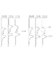
特徴点が3つである場合の具体的な処理を図16を用いて説明する。図16は網膜の断層像であり、A16は断層像中の一つのA−scanラインを表す。PSB16はSobel画像Bから求めたプロファイル(以後、プロファイルPSB16とする)、PMD16はメディアン画像から求めたプロファイル(以後、プロファイルPMD16)である。また、本ステップでは神経線維層・内網状層・外網状層の三層の境界を特定するため、メディアン画像から求めたプロファイルの参照用プロファイルPRE16(以後、プロファイルPRE16)を用意する。プロファイルPRE16は神経線維層・内網状層・外網状層の三層が存在するA−scanラインのプロファイルの典型例である。ここで典型例とは、ノイズが存在せず、且つ、神経線維層・内網状層・外網状層の三層が存在するA−scanラインにおける、各層の輝度の傾向を示したものである。例えば、神経線維層の輝度値は内網状層・外網状層の輝度値よりも高い傾向が経験的にわかっており、そのような輝度の特徴を示すプロファイルPRE16を作成しておく。なお、このプロファイルPRE16は各網膜層の輝度の傾向と位置関係が参照できればよく、部位によって変化する各網膜層の厚さには対応させないため、神経線維層・内網状層・外網状層の三層が存在するA−scanラインであればどこでも使用することができる。これを用いて、三つのピークが神経線維層・内網状層・外網状層に当てはまるか否かを判定する。 A specific process when there are three feature points will be described with reference to FIG. FIG. 16 is a tomographic image of the retina, and A16 represents one A-scan line in the tomographic image. PSB16 is a profile obtained from the Sobel image B (hereinafter referred to as profile PSB16), and PMD16 is a profile obtained from the median image (hereinafter referred to as profile PMD16). In this step, a profile reference profile PRE16 (hereinafter, profile PRE16) obtained from the median image is prepared in order to specify the boundary between the three layers of the nerve fiber layer, the inner mesh layer, and the outer mesh layer. The profile PRE16 is a typical example of an A-scan line profile in which three layers of a nerve fiber layer, an inner reticulated layer, and an outer reticulated layer exist. Here, the typical example shows a tendency of luminance of each layer in an A-scan line in which noise does not exist and three layers of a nerve fiber layer, an inner mesh layer, and an outer mesh layer exist. For example, it has been empirically known that the luminance value of the nerve fiber layer tends to be higher than the luminance values of the inner mesh layer and the outer mesh layer, and a profile PRE16 showing such luminance characteristics is created. The profile PRE16 only needs to be able to refer to the luminance trend and positional relationship of each retinal layer, and does not correspond to the thickness of each retinal layer that changes depending on the region. Any A-scan line with a layer can be used. Using this, it is determined whether or not the three peaks apply to the nerve fiber layer, the inner mesh layer, and the outer mesh layer.
まず、プロファイルPSB16における各ピーク間の平均輝度値を算出する。輝度値はプロファイルPSB16の位置に対応したプロファイルPMD16の値を用いる。プロファイルPSB17における三つのピークを、浅い位置から第一ピーク、第二ピーク、第三ピークとする。平均値を算出する範囲は、内境界膜と第一ピーク間、第一ピークと第二ピーク間、第二ピークと第三ピーク間、第三ピークと視細胞内節外節接合部間とする。これらを順にピーク間A1、ピーク間A2、ピーク間A3,ピーク間A4とする。さらに第二ピークと第三ピークの間を二等分し、第二ピークに近い方の範囲(以後、ピーク間A31とする)と第三ピークに近い方の範囲(以後、ピーク間A32とする)についても、プロファイルPMD16から平均輝度値を算出する。 First, an average luminance value between the peaks in the profile PSB16 is calculated. As the luminance value, the value of the profile PMD16 corresponding to the position of the profile PSB16 is used. The three peaks in the profile PSB17 are defined as a first peak, a second peak, and a third peak from a shallow position. The average value is calculated between the inner boundary membrane and the first peak, between the first peak and the second peak, between the second peak and the third peak, and between the third peak and the photoreceptor inner / outer segment junction. . These are sequentially referred to as A1 between peaks, A2 between peaks, A3 between peaks, and A4 between peaks. Further, the second peak and the third peak are divided into two equal parts, and the range closer to the second peak (hereinafter referred to as A31 between peaks) and the range closer to the third peak (hereinafter referred to as A32 between peaks). ) Also calculates an average luminance value from the profile PMD16.
次にプロファイルPRE16に習って、算出した平均輝度値の大小関係を比較する。プロファイルPRE16から、平均輝度値において、ピーク間A1>ピーク間A2、ピーク間A1>ピーク間A3、ピーク間A3>ピーク間A4、ピーク間A31<ピーク間A32という条件が導かれる。これらに算出した平均輝度値を当てはめて、神経線維層・内網状層・外網状層の三層の妥当性を確かめる。条件を全て満たしたとき、第一ピーク、第二ピーク、第三ピークはそれぞれ神経線維層・内網状層・外網状層の境界として特定され、データサーバ113に保存される。条件を一つでも満たさないものがあったとき、そのA−scanラインでは網膜層境界を特定しない。 Next, the magnitude relationship of the calculated average luminance values is compared according to the profile PRE16. From the profile PRE16, conditions of peak-to-peak A1> peak-to-peak A2, peak-to-peak A1> peak-to-peak A3, peak-to-peak A3> peak-to-peak A4, peak-to-peak A31 <peak-to-peak A32 are derived. By applying the calculated average luminance value to these, the validity of the three layers of the nerve fiber layer, the inner mesh layer, and the outer mesh layer is confirmed. When all the conditions are satisfied, the first peak, the second peak, and the third peak are specified as boundaries of the nerve fiber layer, the inner network layer, and the outer network layer, respectively, and stored in the data server 113. When there is something that does not satisfy even one condition, the retinal layer boundary is not specified in the A-scan line.
特徴点が3つである場合の具体的な処理を図17を用いて説明する。図17は網膜の断層像であり、A17は断層像中の一つのA−scanラインを表す。PSB17はSobel画像Bから求めたプロファイル(以後、プロファイルPSB17とする)、PMD17はメディアン画像から求めたプロファイル(以後、プロファイルPMD17)である。また、本ステップでは内網状層・外網状層の二層の境界を特定するため、メディアン画像から求めたプロファイルの参照用プロファイルPRE17(以後、プロファイルPRE17)を用意する。この参照用プロファイルは内網状層・外網状層の二層が存在するA−scanラインのプロファイルの典型例である。典型例はステップS1402の考え方と同様に、ノイズが存在せず、且つ、内網状層・外網状層の二層が存在するA−scanラインにおける、各層の輝度の傾向を示したものであり、対象の二層が存在するA−scanラインであればどこでも使用することができる。これを用いて、二つのピークが内網状層・外網状層に当てはまるか否かを判定する。 A specific process when there are three feature points will be described with reference to FIG. FIG. 17 is a tomographic image of the retina, and A17 represents one A-scan line in the tomographic image. PSB17 is a profile obtained from the Sobel image B (hereinafter referred to as profile PSB17), and PMD17 is a profile obtained from the median image (hereinafter referred to as profile PMD17). Also, in this step, a reference profile PRE17 (hereinafter referred to as profile PRE17) of the profile obtained from the median image is prepared in order to specify the boundary between the inner mesh layer and the outer mesh layer. This reference profile is a typical example of an A-scan line profile in which two layers of an inner mesh layer and an outer mesh layer exist. The typical example shows the tendency of the brightness of each layer in the A-scan line where there is no noise and there are two layers of the inner mesh layer and the outer mesh layer, as in the idea of step S1402. Any A-scan line where there are two layers of interest can be used. Using this, it is determined whether or not the two peaks apply to the inner network layer and the outer network layer.
本ステップでも、まず、プロファイルPSB17とプロファイルPMD17を用いて、各ピーク間の平均輝度値を算出する。プロファイルPSB17における2つのピークを、浅い位置から第一ピーク、第二ピークとする。平均輝度値を算出する範囲は、内境界膜と第一ピーク間、第一ピークと第二ピーク間、第二ピークと視細胞内節外節接合部間とする。これらピーク間を順にピーク間B1、ピーク間B2、ピーク間B3とする。さらに第一ピークと第二ピークの間を二等分し、第一ピークに近い方の範囲(以後、ピーク間B21とする)と第二ピークに近い方の範囲(以後、ピーク間B22とする)についても、プロファイルPMD17から平均輝度値を算出する。 Also in this step, first, the average luminance value between the peaks is calculated using the profile PSB17 and the profile PMD17. Two peaks in the profile PSB17 are defined as a first peak and a second peak from a shallow position. The range for calculating the average luminance value is between the inner boundary film and the first peak, between the first peak and the second peak, and between the second peak and the photoreceptor inner / outer node junction. These peaks are referred to as peak-to-peak B1, peak-to-peak B2, and peak-to-peak B3 in order. Further, the first peak and the second peak are divided into two equal parts, the range closer to the first peak (hereinafter referred to as B21 between peaks) and the range closer to the second peak (hereinafter referred to as B22 between peaks). ) Also calculates the average luminance value from the profile PMD17.
次にプロファイルの典型例に習って、算出した平均輝度値の大小関係を比較する。PRE17から、平均輝度値において、ピーク間B1>ピーク間B2、ピーク間B2>ピーク間B3、ピーク間B21<ピーク間B22という条件が導かれる。これらを算出した平均輝度値を当てはめて、内網状層・外網状層の二層の妥当性を確かめる。条件を全て満たしたとき、第一ピーク、第二ピークはそれぞれ内網状層・外網状層の境界として特定され、データサーバ113に保存される。条件を一つでも満たさないものがあったとき、そのA−scanラインでは網膜層境界を特定しない。 Next, following the typical example of the profile, the magnitude relationship of the calculated average luminance values is compared. From the PRE 17, in the average luminance value, conditions of peak-to-peak B1> peak-to-peak B2, peak-to-peak B2> peak-to-peak B3, peak-to-peak B21 <peak-to-peak B22 are derived. The validity of the two layers of the inner mesh layer and the outer mesh layer is confirmed by applying the calculated average luminance value. When all the conditions are satisfied, the first peak and the second peak are specified as the boundary between the inner network layer and the outer network layer, and are stored in the data server 113. When there is something that does not satisfy even one condition, the retinal layer boundary is not specified in the A-scan line.
このように、特徴点の数に応じて選択されたテンプレートが処理対象となるAスキャンラインに適合するか否かを判定することにより、テンプレート選択の誤りに起因する層境界の特定の誤りを軽減することができる。また、テンプレート情報の適合を判断する際に、境界間の領域の輝度値を用いることで、層境界の同定の誤りを減らすことができる。 In this way, by determining whether the template selected according to the number of feature points is compatible with the A scan line to be processed, it is possible to reduce specific errors in the layer boundary caused by template selection errors. can do. Further, when determining the suitability of the template information, the layer boundary identification error can be reduced by using the luminance value of the region between the boundaries.
本実施例は、アルゴリズム切り換え部において、Sobel画像のプロファイルにおけるピークの数ではなく、プロファイル同士のパターンマッチングによってアルゴリズムを切り換える実施例である。具体的には、処理対象となるメディアン画像のプロファイルと各参照用プロファイルを位置合わせし、対応する信号間の距離を算出する。そして、その距離の累積値が最も小さい参照プロファイルの層構造に従って、網膜層境界特定のアルゴリズムを切り換える。本実施形態では、神経線維層・内網状層・外網状層を特定する際のアルゴリズム切り換えを例に説明する。 In this embodiment, the algorithm switching unit switches the algorithm by pattern matching between profiles instead of the number of peaks in the profile of the Sobel image. Specifically, the profile of the median image to be processed and each reference profile are aligned, and the distance between corresponding signals is calculated. Then, the algorithm for specifying the retinal layer boundary is switched according to the layer structure of the reference profile having the smallest accumulated value of the distance. In the present embodiment, algorithm switching when specifying a nerve fiber layer, an inner mesh layer, and an outer mesh layer will be described as an example.
本実施例におけるテンプレート選択部107及び層境界特定部108が実行する処理の流れを示すフローチャートを図18に示す。なお、実施例2において図14のフローチャートに示される処理と同様の処理については説明を省略する。
FIG. 18 is a flowchart showing the flow of processing executed by the
(ステップS1802)
ステップS1802において、テンプレート選択部107では、A−scanライン毎に全ての参照用プロファイルとの類似度を算出し、その類似度を基にアルゴリズムを切り換える。ここで、類似度とは、パターンマッチング手法によるプロファイル同士の比較によって算出されるものであり、その算出方法は下記に示す。
(Step S1802)
In step S1802, the
具体的な処理は図19を用いて説明する。図19のA19は断層像中の一つのA−scanラインを表す。PMD190はメディアン画像から求めたプロファイル(以後、プロファイルPMD190)である。PRE191は神経線維層・内網状層・外網状層の三層が存在する場合の参照用プロファイル(以後、プロファイルPRE191)であり、RPE192は内網状層・外網状層の二層が存在する場合の参照用プロファイル(以後、プロファイルPRE192)である。 Specific processing will be described with reference to FIG. A19 in FIG. 19 represents one A-scan line in the tomographic image. PMD 190 is a profile obtained from the median image (hereinafter, profile PMD 190). PRE191 is a reference profile (hereinafter referred to as profile PRE191) when there are three layers of nerve fiber layer, inner mesh layer, and outer mesh layer, and RPE192 is a case where there are two layers of inner mesh layer and outer mesh layer. This is a reference profile (hereinafter profile PRE192).
まず、処理対象となるA−scanラインのメディアン画像プロファイルと各参照用プロファイルの位置合わせを行う。位置合わせはステップS1406までに特定した内境界膜・視細胞内節外節接合部の位置を基に行う。プロファイルPMD190の内境界膜・視細胞内節外節接合部の位置を端として合わせて、プロファイルPRE191、プロファイルPRE192を伸縮させる。そして、図20にて示されるPMT201・PMT202のように、プロファイルPMD190に、プロファイルPRE191・プロファイルPRE192をそれぞれ重ね合わせて、対応する点同士の距離を算出していく。ここでの距離は位置合わせ後のプロファイルにおいて、同じz座標でのx座標の差とする。この距離の累積値を各参照用プロファイルについて算出する。
First, the median image profile of the A-scan line to be processed and each reference profile are aligned. The alignment is performed based on the position of the inner boundary membrane / photocell inner / outer joint joint specified up to step S1406. The profile PRE191 and the profile PRE192 are expanded and contracted with the position of the inner boundary membrane / photocell inner / outer node joint portion of the profile PMD 190 as the end. Then, like the
(ステップS1803)
ステップS1803では、テンプレート選択部107は算出した類似度に応じて最も適するテンプレートを選択する。ここではテンプレート選択部107累積値の最も低い(つまり、類似度が最も高い)参照用プロファイルの構造に沿ったテンプレートを選択する。選択されたテンプレート情報には、層境界の位置及び種類の情報が対応付けられているため、テンプレート選択部107により処理対象となるAスキャンラインにおいて特定されるべき層境界の種類が決定されることとなる。本実施形態では、プロファイルPRE191との類似度が高い場合、そのA−scanラインには神経線維層・内網状層・外網状層が存在する可能性が高いと判定し、ステップS1804へ進む。
(Step S1803)
In step S1803, the
このように、パターンマッチング処理を行ってテンプレートを選択し、テンプレート情報に基づいて層境界の位置及び種類を特定するため、画像における構造や特徴の変化に対応して層境界の種類及び位置を特定することができる。 In this way, pattern matching processing is performed to select a template, and the position and type of the layer boundary are specified based on the template information. Therefore, the type and position of the layer boundary is specified in response to changes in structure and features in the image. can do.
なお、本実施例のようにパターンマッチングによるテンプレート選択を行う場合には、算出された類似度が高い場合には実施例2のような適合性の判定処理を行わなくてもよい。類似度が高ければ、適合していると考えられるからである。この場合、特徴点の数に応じた選択処理とその後の判定処理とを行う場合に比べて処理を簡略化することができる。また逆に、実施例2において、判定部が行う適合性の判定処理として本実施例に特徴的なパターンマッチング処理を行い、算出された類似度が所定の閾値を超えるか否かに応じて判定を行ってもよい。 When performing template selection by pattern matching as in the present embodiment, the suitability determination process as in the second embodiment may not be performed if the calculated similarity is high. This is because if the degree of similarity is high, it is considered to be compatible. In this case, the processing can be simplified as compared with the case where the selection processing according to the number of feature points and the subsequent determination processing are performed. Conversely, in the second embodiment, pattern matching processing characteristic of the present embodiment is performed as suitability determination processing performed by the determination unit, and determination is made based on whether or not the calculated similarity exceeds a predetermined threshold value. May be performed.
また、本実施例におけるテンプレートは、予め層境界が特定された断層画像のプロファイルの平均またはメディアンを取って作成される参照用のプロファイルそのものであってもよい。 Further, the template in the present embodiment may be a reference profile itself created by taking an average or median of profiles of tomographic images in which layer boundaries are specified in advance.
本実施例は、層境界補間部109が実行する補間処理において、探索範囲内における輝度変化のピークのうち、特定済みの層境界の深さの平均値に最も近い位置を層境界の位置として特定する。本実施例では、神経線維層の界面、内網状層の界面、外網状層の界面についての補間処理を説明する。
In this embodiment, in the interpolation processing executed by the layer
本実施形態における網膜層境界補間処理のフローチャートを図21に示す。なお、実施例1の図11に示される処理と重複する部分については説明を一部省略する。 A flowchart of the retinal layer boundary interpolation process in this embodiment is shown in FIG. Note that a part of the description of the same part as the process shown in FIG.
(ステップS2103)
ステップS2103において、層境界補間部109では、本ステップまでに網膜層境界を特定できていないA−scanラインについて、網膜層境界を特定するための特徴量を算出する。特徴量は本ステップまでに網膜層境界が特定されているA−scanラインの情報から算出される。本実施形態では、網膜層境界を特定できていないA−scanラインを中心とした局所領域(以後、近傍領域とする)を考え、その領域内の特定されている網膜層境界を基に特徴量を算出する。特徴量の算出はステップS1103と同様に、図12のような網膜層境界が特定されていないA−scanラインを中心とした近傍領域を考える。近傍領域内で特定されている各網膜層境界のz座標平均値を求めて特徴量とする。特徴量を算出するか否かの判定条件もステップS1102と同様に、近傍領域内に網膜層境界が特定されているA−scanラインが所定の数より大きいか小さいかで行う。この特徴量として算出した各網膜層のz座標平均値を用いて、層境界補間部109はその座標値の前後、所定の範囲内を網膜層境界の探索範囲として設定する。本実施形態では、所定の範囲はz座標平均値の前後5画素とする。
(Step S2103)
In step S2103, the layer
(ステップS2106)
探索範囲内でSobel画像Bのプロファイルにおけるピークが探索され、ピークが存在したとき、層境界補間部109はその中で所定の閾値以上一番大きなピークを網膜層境界として特定する。そのようなピークが二つ以上ある場合には、算出されたZ座標の平均値に最も近い位置のピークを層境界の位置として特定する。これは、複数の層境界が近接して存在する場合に、一つの層境界を特定するための探索範囲内に2以上の層境界が含まれる場合に対応して、近傍領域において特定済みの層境界の深さの平均値に最も近いピークを選択することとしたものである。これにより、層境界を精度よく特定することができる。
(Step S2106)
A peak in the profile of the Sobel image B is searched within the search range, and when a peak exists, the layer
図22は神経線維層・内網状層・外網状層の三層が存在するA−scanラインにおけるSobel画像Bのプロファイルの例である。図22のプロファイルPSB220はノイズ等の影響によりによって4つのピークが存在し、且つ、大きさからもどこが各網膜層境界であるか、判断が難しい。しかし、近傍領域から算出したz座標平均値を基に本ステップS2104により設定される神経線維層境界の探索範囲CN、内網状層の境界の探索範囲CI、外網状層の境界の探索範囲COを用いることで、各網膜層境界を精度よく特定することができる。 FIG. 22 is an example of a profile of the Sobel image B in the A-scan line in which three layers of a nerve fiber layer, an inner mesh layer, and an outer mesh layer exist. The profile PSB 220 in FIG. 22 has four peaks due to the influence of noise and the like, and it is difficult to determine where each retinal layer boundary is based on the size. However, the nerve fiber layer boundary search range CN, the inner network layer boundary search range CI, and the outer network layer boundary search range CO set in step S2104 based on the z coordinate average value calculated from the neighboring region By using it, each retinal layer boundary can be specified with high accuracy.
このように、ピークの位置が複数発見されても、既に特定済みのZ座標平均値に最も近いピークの位置を層境界の位置として特定することにより、網膜層境界を精度よく特定することができる。 As described above, even when a plurality of peak positions are found, the retinal layer boundary can be accurately identified by specifying the peak position closest to the already specified Z coordinate average as the layer boundary position. .
(その他の実施例)
なお、上述した本実施形態における記述は本発明に係る好ましい画像処理装置の一例であり、本発明はこれに限定されるものではない。また、前記実施例1乃至4の画像処理装置101を、ソフトウェアを用いて実現することも可能である。その場合には、先述の各実施例における画像処理装置101の処理を実行するためのプログラムを記録した記憶媒体を、システムあるいは装置に供給する。そしてそのシステムあるいは装置のコンピュータ(またはCPUやMPU)が記憶媒体に格納されたプログラムコードを読出し実行することによっても、達成されるものである。 この場合、記憶媒体から読出されたプログラムコード自体が前述した実施例記載の機能を実現することになり、そのプログラムコードを記憶した記憶媒体は本発明を構成することになる。
(Other examples)
The description in the above-described embodiment is an example of a preferable image processing apparatus according to the present invention, and the present invention is not limited to this. In addition, the image processing apparatus 101 according to the first to fourth embodiments can be realized using software. In that case, a storage medium storing a program for executing the processing of the image processing apparatus 101 in each of the above-described embodiments is supplied to the system or apparatus. This can also be achieved by the computer (or CPU or MPU) of the system or apparatus reading and executing the program code stored in the storage medium. In this case, the program code itself read from the storage medium realizes the functions described in the above-described embodiments, and the storage medium storing the program code constitutes the present invention.
上述の実施例では、取得する複数の断層像群からなる三次元画像データに対して解析処理を行う場合について説明する。しかし、三次元画像データから注目すべき二次元の断層像を選択して、選択した断層像に対して処理を行う構成であってもよい。例えば、予め定めた眼底の特定部位(例えば中心窩)を含む断層像に対して処理を行ってもよい。この場合、検出される層の境界等は、いずれも当該断面上における二次元のデータとなる。 In the above-described embodiment, a case where analysis processing is performed on three-dimensional image data including a plurality of tomographic image groups to be acquired will be described. However, the configuration may be such that a notable two-dimensional tomographic image is selected from the three-dimensional image data, and the selected tomographic image is processed. For example, the processing may be performed on a tomographic image including a predetermined specific part (for example, fovea) of the fundus. In this case, the detected layer boundaries are all two-dimensional data on the cross section.
上述の実施例においては層境界を特定していたが、これに限らず、テンプレート情報を用いて層の種類及び位置を特定してもよい。この際には、層境界の位置に対応するエッジの輝度変化の大きさまたは輝度値、層領域の輝度値またはその大小関係等の情報がテンプレート情報として必要となる。テンプレート情報としては、黄斑部、視神経乳頭部、血管が存在する網膜の領域、または血管が存在しない網膜の領域などが考えられる。 In the above-described embodiment, the layer boundary is specified. However, the present invention is not limited to this, and the type and position of the layer may be specified using template information. At this time, information such as the magnitude or luminance value of the luminance change of the edge corresponding to the position of the layer boundary, the luminance value of the layer region or the magnitude relationship thereof is required as the template information. Examples of the template information include a macular portion, an optic papilla, a retina region where blood vessels exist, or a retina region where blood vessels do not exist.
さらには、層境界の数や層領域の輝度値に基づいて黄斑部であるか否か、視神経乳頭部であるか否かなどの構造を判定することもできる。例えば、黄斑部であるか否か、視神経乳頭部であるか否か、その他の領域であるか否か、血管が存在する領域であるか否か、白斑が存在する領域であるか否か網膜はく離が存在する領域であるか否か、その他の網膜層の構造を判定することができる。または、断層画像に現れる特徴として、血管や白斑による偽像があるか否かを構造として判定することも可能である。 Furthermore, it is also possible to determine the structure such as whether it is a macular part or whether it is an optic papilla based on the number of layer boundaries and the luminance value of the layer region. For example, whether it is the macula, whether it is the optic papilla, whether it is another area, whether it is an area where blood vessels are present, whether it is an area where vitiligo is present The structure of other retinal layers can be determined. Alternatively, it is also possible to determine as a structure whether or not there is a false image due to blood vessels or vitiligo as a feature that appears in a tomographic image.
上述の実施例における層境界の補間処理は、上述のテンプレートにより層境界を特定する処理とともに用いずともよい。例えば、その他の方法により層境界の一部分が特定されている場合に適用してもよい。 The layer boundary interpolation processing in the above-described embodiment may not be used together with the processing for specifying the layer boundary using the above-described template. For example, the present invention may be applied when a part of the layer boundary is specified by another method.
なお、網膜に限らず、前眼部の断層画像であってもよい。前眼部も角膜、水晶体、硝子体等からなる層構造が形成されており、信号光の入射する方向つまり深さ方向に対して積層された層構造を有している。そのため前眼部の断層画像に対しても本発明を適用可能である。その場合には、前眼部の断層画像のプロファイルにおける複数の構造に対応した複数のテンプレートを記憶部111に保持しておく。 The tomographic image of the anterior segment is not limited to the retina. The anterior segment also has a layer structure formed of a cornea, a crystalline lens, a vitreous body, and the like, and has a layer structure laminated in the direction in which signal light enters, that is, the depth direction. Therefore, the present invention can also be applied to a tomographic image of the anterior segment. In that case, a plurality of templates corresponding to a plurality of structures in the profile of the tomographic image of the anterior segment is held in the storage unit 111.
上述の実施例では画像処理システム100により本発明を実施する例を示したが、これに限らず、画像処理装置101の機能を光干渉断層撮像装置内に実装してもよい。
In the above-described embodiment, an example in which the present invention is implemented by the
また上述の実施例では光干渉断層撮像装置により得られる断層画像を例に説明したが、これに限らず、超音波断層撮像装置その他の撮影対象の内部構造を画像化する装置により得られた断層画像に対して本発明を適用してもよい。 In the above-described embodiments, the tomographic image obtained by the optical coherence tomographic imaging apparatus has been described as an example. However, the present invention is not limited to this, and the tomographic image obtained by the ultrasonic tomographic imaging apparatus or other apparatus that images the internal structure of the imaging target. The present invention may be applied to images.
100 画像処理システム
101 画像処理装置
102 断層像取得装置
105 輝度情報生成部
106 検出部
107 テンプレート選択部
108 層境界特定部
109 層境界補間部
1071 構造判定部
DESCRIPTION OF
Claims (24)
前記取得された断層画像の深さ方向に積層された各層の層境界を検出する検出手段と、
前記断層画像の所定の位置において前記検出された層境界の数を算出する算出手段と、
前記層境界の数に応じて前記検出された層の種類を判定する判定手段と、
を有することを特徴とする画像処理装置。 An acquisition means for acquiring a tomographic image to be imaged;
Detecting means for detecting a layer boundary of each layer laminated in the depth direction of the acquired tomographic image;
Calculating means for calculating the number of layer boundaries detected at a predetermined position of the tomographic image;
Determining means for determining the type of the detected layer according to the number of layer boundaries;
An image processing apparatus comprising:
前記選択されたテンプレート情報と前記検出された層境界とに基づいて前記所定位置における層境界の種類を特定する特定手段を有することを特徴とする請求項2に記載の画像処理装置。 The determining means includes at least one of a plurality of template information indicating types of layer boundaries existing in the depth direction at each of the plurality of positions to be imaged according to the number of layer boundaries detected at the predetermined position. Selecting means for selecting two template information,
The image processing apparatus according to claim 2, further comprising a specifying unit that specifies a type of a layer boundary at the predetermined position based on the selected template information and the detected layer boundary.
前記選択手段が選択するテンプレート情報は、前記断層画像の深さ方向に存在する層境界の位置及び種類と、層領域の輝度値の情報を有しており、層境界の数と関連付けられて記憶部に記憶されることを特徴とする請求項6に記載の画像処理装置。 The determining means includes at least one of a plurality of template information indicating types of layer boundaries existing in the depth direction at each of the plurality of positions to be imaged according to the number of layer boundaries detected at the predetermined position. Selecting means for selecting two template information,
The template information selected by the selection means includes information on the position and type of the layer boundary existing in the depth direction of the tomographic image and the luminance value of the layer region, and is stored in association with the number of layer boundaries. The image processing apparatus according to claim 6, wherein the image processing apparatus is stored in the unit.
前記判定の結果に基づいて前記選択されたテンプレート情報と前記検出された層境界とに基づいて前記所定位置における層境界の種類を特定する特定手段を有することを特徴とする請求項7に記載の画像処理装置。 The selection unit selects template information according to the number of detected layer boundaries, and information on luminance values of the layer area included in the selected template information and a pixel row arranged in the depth direction at the predetermined position And determining whether the selected template information matches the predetermined position based on the information of
8. The specifying unit according to claim 7, further comprising: specifying a layer boundary type at the predetermined position based on the selected template information based on the determination result and the detected layer boundary. Image processing device.
前記検出手段は、前記生成されたプロファイルに基づいて前記断層画像の深さ方向における所定の閾値より大きいエッジを取得し、該エッジの位置を前記層境界の位置として検出することを特徴とする請求項1乃至12のいずれか1項に記載の画像処理装置。 Generating means for generating, from the tomographic image, a profile indicating the relationship between the position in the depth direction and the luminance at a predetermined position in the horizontal direction of the tomographic image;
The detection means acquires an edge larger than a predetermined threshold in the depth direction of the tomographic image based on the generated profile, and detects the position of the edge as the position of the layer boundary. Item 13. The image processing apparatus according to any one of Items 1 to 12.
ことを特徴とする請求項1乃至13のいずれか1項に記載の画像処理装置。 The determination means includes a layer boundary type or position at a predetermined position in the horizontal direction of the tomographic image, a layer type, presence or absence of a false image at the predetermined position, or whether the predetermined position is a macular portion of the retina, The structure of the eye part as the imaging target is determined as to whether or not the optic papilla of the retina, or the region other than the macula and the optic papilla. 14. The image processing device according to any one of items 13.
前記眼部の断層画像の水平方向の複数の位置における深さ方向へのエッジの数と、該エッジに対応する層境界の種類と関連付けて記憶する記憶手段と、
前記取得された断層画像の水平方向の所定位置において深さ方向に並ぶ画素列からエッジを検出する検出手段と、
前記検出されたエッジの数と前記記憶された情報とから前記エッジに対応する層境界の種類を決定する決定手段と、
を有することを特徴とする画像処理装置。 Obtaining means for obtaining a tomographic image of the eye;
Storage means for storing the number of edges in the depth direction at a plurality of positions in the horizontal direction of the tomographic image of the eye portion in association with the type of layer boundary corresponding to the edges;
Detecting means for detecting an edge from a pixel row arranged in a depth direction at a predetermined position in a horizontal direction of the acquired tomographic image;
Determining means for determining the type of layer boundary corresponding to the edge from the number of detected edges and the stored information;
An image processing apparatus comprising:
前記生成されたプロファイルに基づいて、前記断層画像の水平方向の複数の位置における深さ方向の位置と輝度との関係を示す情報と層境界の種類及び位置を示す情報とを有するテンプレート情報から、前記所定位置に適合するテンプレート情報を選択する選択手段と、
前記選択されたテンプレート情報に基づいて、前記生成されたプロファイルから前記所定位置の層境界を特定する特定手段と、
を有することを特徴とする画像処理装置。 Generating means for generating a profile indicating a relationship between a position in the depth direction and a luminance at a predetermined position in the horizontal direction from a tomographic image of the eye;
Based on the generated profile, from template information having information indicating the relationship between the position in the depth direction and the luminance at a plurality of horizontal positions of the tomographic image and information indicating the type and position of the layer boundary, Selecting means for selecting template information suitable for the predetermined position;
Identifying means for identifying a layer boundary at the predetermined position from the generated profile based on the selected template information;
An image processing apparatus comprising:
前記取得されたエッジの数に応じて、前記所定位置の深さ方向に存在する層の種類を決定する決定手段と、
を有することを特徴とする画像処理装置。 An acquisition means for acquiring an edge in the depth direction at a predetermined position in the horizontal direction of the tomographic image of the eye;
Determining means for determining the type of layer existing in the depth direction of the predetermined position according to the number of the acquired edges;
An image processing apparatus comprising:
前記光干渉断層撮像装置により形成された眼部の断層画像を取得する取得手段と、
前記取得された断層画像の深さ方向に積層された各層の層境界を検出する検出手段と、
前記断層画像の所定の位置において前記検出された層境界の数を算出する算出手段と、
前記層境界の数に応じて前記検出された層の種類を判定する判定手段と、
前記断層画像と該断層画像において前記判定された構造を表示する表示手段と、
を有することを特徴とする画像処理システム。 An optical coherence tomography device;
An acquisition means for acquiring a tomographic image of the eye formed by the optical coherence tomography apparatus;
Detecting means for detecting a layer boundary of each layer laminated in the depth direction of the acquired tomographic image;
Calculating means for calculating the number of layer boundaries detected at a predetermined position of the tomographic image;
Determining means for determining the type of the detected layer according to the number of layer boundaries;
Display means for displaying the tomographic image and the determined structure in the tomographic image;
An image processing system comprising:
前記取得された断層画像の深さ方向に積層された各層の層境界を検出する処理と、
前記断層画像の所定の位置において前記検出された層境界の数を算出する処理と、
前記層境界の数に応じて前記検出された層の種類を判定する処理と、
をコンピュータに実行させることを特徴とするプログラム。 Processing to obtain a tomographic image of the eye,
Processing for detecting a layer boundary of each layer stacked in the depth direction of the acquired tomographic image;
A process of calculating the number of detected layer boundaries at a predetermined position of the tomographic image;
A process of determining the type of the detected layer according to the number of layer boundaries;
A program that causes a computer to execute.
前記取得された断層画像の深さ方向に積層された各層の層境界を検出するステップと、
前記断層画像の所定の位置において前記検出された層境界の数を算出するステップと、
前記層境界の数に応じて前記検出された層の種類を判定するステップと、
を有することを特徴とする画像処理方法。 Obtaining a tomographic image of the eye;
Detecting a layer boundary of each layer stacked in the depth direction of the acquired tomographic image;
Calculating the number of detected layer boundaries at a predetermined position of the tomographic image;
Determining the type of the detected layer according to the number of layer boundaries;
An image processing method comprising:
前記第1プロファイルと前記参照用プロファイルとに基づいて眼部の断層画像の層境界を特定する特定手段と、Identifying means for identifying a layer boundary of a tomographic image of the eye based on the first profile and the reference profile;
を有することを特徴とする画像処理装置。An image processing apparatus comprising:
Priority Applications (4)
| Application Number | Priority Date | Filing Date | Title |
|---|---|---|---|
| JP2010064755A JP5631032B2 (en) | 2010-03-19 | 2010-03-19 | Image processing apparatus, image processing system, image processing method, and program for causing computer to execute image processing |
| US13/583,116 US8620048B2 (en) | 2010-03-19 | 2011-03-11 | Image processing apparatus, image processing system, image processing method, and image processing computer program |
| PCT/JP2011/001457 WO2011114685A1 (en) | 2010-03-19 | 2011-03-14 | Image processing apparatus, image processing system, image processing method, and image processing computer program |
| US14/083,812 US9398846B2 (en) | 2010-03-19 | 2013-11-19 | Image processing apparatus, image processing system, image processing method, and image processing computer program |
Applications Claiming Priority (1)
| Application Number | Priority Date | Filing Date | Title |
|---|---|---|---|
| JP2010064755A JP5631032B2 (en) | 2010-03-19 | 2010-03-19 | Image processing apparatus, image processing system, image processing method, and program for causing computer to execute image processing |
Publications (3)
| Publication Number | Publication Date |
|---|---|
| JP2011194061A JP2011194061A (en) | 2011-10-06 |
| JP2011194061A5 JP2011194061A5 (en) | 2013-05-09 |
| JP5631032B2 true JP5631032B2 (en) | 2014-11-26 |
Family
ID=43984022
Family Applications (1)
| Application Number | Title | Priority Date | Filing Date |
|---|---|---|---|
| JP2010064755A Active JP5631032B2 (en) | 2010-03-19 | 2010-03-19 | Image processing apparatus, image processing system, image processing method, and program for causing computer to execute image processing |
Country Status (3)
| Country | Link |
|---|---|
| US (2) | US8620048B2 (en) |
| JP (1) | JP5631032B2 (en) |
| WO (1) | WO2011114685A1 (en) |
Families Citing this family (28)
| Publication number | Priority date | Publication date | Assignee | Title |
|---|---|---|---|---|
| JP6039156B2 (en) * | 2010-06-08 | 2016-12-07 | キヤノン株式会社 | Image processing apparatus, image processing method, and program |
| JP5938926B2 (en) * | 2012-01-31 | 2016-06-22 | 株式会社ニデック | Optical tomography apparatus and noise removal method |
| EP2693399B1 (en) * | 2012-07-30 | 2019-02-27 | Canon Kabushiki Kaisha | Method and apparatus for tomography imaging |
| JP6130723B2 (en) * | 2013-05-01 | 2017-05-17 | キヤノン株式会社 | Information processing apparatus, information processing apparatus control method, and program |
| US9211064B2 (en) | 2014-02-11 | 2015-12-15 | Welch Allyn, Inc. | Fundus imaging system |
| US9237847B2 (en) | 2014-02-11 | 2016-01-19 | Welch Allyn, Inc. | Ophthalmoscope device |
| EP3129956B1 (en) * | 2014-04-07 | 2020-01-01 | Mimo AG | Method for the analysis of image data representing a three-dimensional volume of biological tissue |
| CN104287763B (en) * | 2014-09-09 | 2016-08-24 | 沈阳东软医疗系统有限公司 | Monitored area method of adjustment and device in a kind of spotting scaming |
| US11045088B2 (en) | 2015-02-27 | 2021-06-29 | Welch Allyn, Inc. | Through focus retinal image capturing |
| US10799115B2 (en) | 2015-02-27 | 2020-10-13 | Welch Allyn, Inc. | Through focus retinal image capturing |
| JP6765786B2 (en) * | 2015-05-01 | 2020-10-07 | キヤノン株式会社 | Image pickup device, operation method of image pickup device, information processing device, and operation method of information processing device |
| JP6736270B2 (en) * | 2015-07-13 | 2020-08-05 | キヤノン株式会社 | Image processing apparatus and method of operating image processing apparatus |
| US10136804B2 (en) | 2015-07-24 | 2018-11-27 | Welch Allyn, Inc. | Automatic fundus image capture system |
| US10573007B2 (en) | 2015-08-19 | 2020-02-25 | Kowa Company, Ltd. | Image processing apparatus, image processing method, and image processing program |
| JP6647305B2 (en) * | 2015-08-19 | 2020-02-14 | 興和株式会社 | Image processing apparatus, image processing method, and image processing program |
| JP6632267B2 (en) * | 2015-09-04 | 2020-01-22 | キヤノン株式会社 | Ophthalmic apparatus, display control method and program |
| US10506165B2 (en) | 2015-10-29 | 2019-12-10 | Welch Allyn, Inc. | Concussion screening system |
| US10772495B2 (en) | 2015-11-02 | 2020-09-15 | Welch Allyn, Inc. | Retinal image capturing |
| WO2017120217A1 (en) | 2016-01-07 | 2017-07-13 | Welch Allyn, Inc. | Infrared fundus imaging system |
| US10602926B2 (en) | 2016-09-29 | 2020-03-31 | Welch Allyn, Inc. | Through focus retinal image capturing |
| US10285589B2 (en) | 2016-09-30 | 2019-05-14 | Welch Allyn, Inc. | Fundus image capture system |
| US11096574B2 (en) | 2018-05-24 | 2021-08-24 | Welch Allyn, Inc. | Retinal image capturing |
| WO2020160446A1 (en) * | 2019-02-01 | 2020-08-06 | The Johns Hopkins University | Layer boundary evolution for macular optical coherence tomography segmentation |
| JP6888643B2 (en) * | 2019-03-22 | 2021-06-16 | 株式会社ニデック | OCT analysis processing device and OCT data processing program |
| CN110599491B (en) * | 2019-09-04 | 2024-04-12 | 腾讯医疗健康(深圳)有限公司 | Priori information-based eye image segmentation method, apparatus, device and medium |
| WO2021067435A1 (en) * | 2019-10-01 | 2021-04-08 | Yuscan Usa, Llc | Devices and methods for determining a disease state based total lens fluorescence |
| TWI728818B (en) * | 2020-05-22 | 2021-05-21 | 貞安有限公司 | Home monitoring system and method for fundus image in a schedule |
| KR102530717B1 (en) * | 2020-06-19 | 2023-05-09 | 가부시키가이샤 스크린 홀딩스 | Image processing method, program and recording medium |
Family Cites Families (13)
| Publication number | Priority date | Publication date | Assignee | Title |
|---|---|---|---|---|
| US6276798B1 (en) * | 1998-09-29 | 2001-08-21 | Applied Spectral Imaging, Ltd. | Spectral bio-imaging of the eye |
| EP1976424B1 (en) | 2006-01-19 | 2011-09-21 | Optovue, Inc. | A method of eye examination by optical coherence tomography |
| US7768652B2 (en) * | 2006-03-16 | 2010-08-03 | Carl Zeiss Meditec, Inc. | Methods for mapping tissue with optical coherence tomography data |
| WO2007133964A2 (en) | 2006-05-12 | 2007-11-22 | The General Hospital Corporation | Processes, arrangements and systems for providing a fiber layer thickness map based on optical coherence tomography images |
| JP4855150B2 (en) * | 2006-06-09 | 2012-01-18 | 株式会社トプコン | Fundus observation apparatus, ophthalmic image processing apparatus, and ophthalmic image processing program |
| JP5095167B2 (en) * | 2006-09-19 | 2012-12-12 | 株式会社トプコン | Fundus observation apparatus, fundus image display apparatus, and fundus observation program |
| JP4921201B2 (en) * | 2007-02-23 | 2012-04-25 | 株式会社トプコン | Optical image measurement device and program for controlling optical image measurement device |
| US8363783B2 (en) | 2007-06-04 | 2013-01-29 | Oraya Therapeutics, Inc. | Method and device for ocular alignment and coupling of ocular structures |
| JP4940070B2 (en) * | 2007-09-10 | 2012-05-30 | 国立大学法人 東京大学 | Fundus observation apparatus, ophthalmic image processing apparatus, and program |
| JP5165510B2 (en) | 2008-09-09 | 2013-03-21 | 住友化学株式会社 | Vent pipe in storage tank |
| JP4810562B2 (en) * | 2008-10-17 | 2011-11-09 | キヤノン株式会社 | Image processing apparatus and image processing method |
| JP5473358B2 (en) * | 2009-03-02 | 2014-04-16 | キヤノン株式会社 | Image processing apparatus, image processing method, and program |
| US9700210B2 (en) * | 2009-03-02 | 2017-07-11 | Canon Kabushiki Kaisha | Image processing apparatus and method for controlling the same |
-
2010
- 2010-03-19 JP JP2010064755A patent/JP5631032B2/en active Active
-
2011
- 2011-03-11 US US13/583,116 patent/US8620048B2/en not_active Expired - Fee Related
- 2011-03-14 WO PCT/JP2011/001457 patent/WO2011114685A1/en active Application Filing
-
2013
- 2013-11-19 US US14/083,812 patent/US9398846B2/en active Active
Also Published As
| Publication number | Publication date |
|---|---|
| US20130004046A1 (en) | 2013-01-03 |
| US8620048B2 (en) | 2013-12-31 |
| WO2011114685A1 (en) | 2011-09-22 |
| JP2011194061A (en) | 2011-10-06 |
| US20140176905A1 (en) | 2014-06-26 |
| US9398846B2 (en) | 2016-07-26 |
Similar Documents
| Publication | Publication Date | Title |
|---|---|---|
| JP5631032B2 (en) | Image processing apparatus, image processing system, image processing method, and program for causing computer to execute image processing | |
| JP5645432B2 (en) | Image processing apparatus, image processing system, image processing method, and program for causing computer to execute image processing | |
| US9872614B2 (en) | Image processing apparatus, method for image processing, image pickup system, and computer-readable storage medium | |
| JP5751815B2 (en) | Image processing apparatus, photographing system, image processing method, and program | |
| JP5693101B2 (en) | Image processing apparatus and image processing method | |
| EP2458550B1 (en) | Analysis of retinal images | |
| JP2020058800A (en) | Image processing device, image processing method, and image processing program | |
| US9918625B2 (en) | Image processing apparatus and control method of image processing apparatus | |
| KR101894808B1 (en) | Ophthalmologic apparatus and ophthalmologic apparatus control method | |
| US10758122B2 (en) | Volume analysis and display of information in optical coherence tomography angiography | |
| JP6025882B2 (en) | Image processing apparatus, image processing method, and program | |
| US10111582B2 (en) | Image processing device and method to identify disease in an ocular fundus image | |
| US10916012B2 (en) | Image processing apparatus and image processing method | |
| JP6243957B2 (en) | Image processing apparatus, ophthalmic system, control method for image processing apparatus, and image processing program | |
| WO2020075719A1 (en) | Image processing device, image processing method, and program | |
| JP2018057828A (en) | Image processing apparatus and image processing method | |
| JP6061984B2 (en) | Image processing apparatus, image processing method, and program | |
| JP7086708B2 (en) | Image processing equipment, image processing methods and programs |
Legal Events
| Date | Code | Title | Description |
|---|---|---|---|
| A521 | Request for written amendment filed |
Free format text: JAPANESE INTERMEDIATE CODE: A523 Effective date: 20130319 |
|
| A621 | Written request for application examination |
Free format text: JAPANESE INTERMEDIATE CODE: A621 Effective date: 20130319 |
|
| A131 | Notification of reasons for refusal |
Free format text: JAPANESE INTERMEDIATE CODE: A131 Effective date: 20140624 |
|
| A521 | Request for written amendment filed |
Free format text: JAPANESE INTERMEDIATE CODE: A523 Effective date: 20140820 |
|
| TRDD | Decision of grant or rejection written | ||
| A01 | Written decision to grant a patent or to grant a registration (utility model) |
Free format text: JAPANESE INTERMEDIATE CODE: A01 Effective date: 20140909 |
|
| A61 | First payment of annual fees (during grant procedure) |
Free format text: JAPANESE INTERMEDIATE CODE: A61 Effective date: 20141007 |
|
| R151 | Written notification of patent or utility model registration |
Ref document number: 5631032 Country of ref document: JP Free format text: JAPANESE INTERMEDIATE CODE: R151 |