JP5628144B2 - Object and motion detection - Google Patents
Object and motion detection Download PDFInfo
- Publication number
- JP5628144B2 JP5628144B2 JP2011500289A JP2011500289A JP5628144B2 JP 5628144 B2 JP5628144 B2 JP 5628144B2 JP 2011500289 A JP2011500289 A JP 2011500289A JP 2011500289 A JP2011500289 A JP 2011500289A JP 5628144 B2 JP5628144 B2 JP 5628144B2
- Authority
- JP
- Japan
- Prior art keywords
- impulse response
- filter
- matrix
- signal
- image
- Prior art date
- Legal status (The legal status is an assumption and is not a legal conclusion. Google has not performed a legal analysis and makes no representation as to the accuracy of the status listed.)
- Active
Links
Images


Classifications
-
- G—PHYSICS
- G06—COMPUTING; CALCULATING OR COUNTING
- G06F—ELECTRIC DIGITAL DATA PROCESSING
- G06F3/00—Input arrangements for transferring data to be processed into a form capable of being handled by the computer; Output arrangements for transferring data from processing unit to output unit, e.g. interface arrangements
- G06F3/01—Input arrangements or combined input and output arrangements for interaction between user and computer
- G06F3/017—Gesture based interaction, e.g. based on a set of recognized hand gestures
-
- G—PHYSICS
- G01—MEASURING; TESTING
- G01S—RADIO DIRECTION-FINDING; RADIO NAVIGATION; DETERMINING DISTANCE OR VELOCITY BY USE OF RADIO WAVES; LOCATING OR PRESENCE-DETECTING BY USE OF THE REFLECTION OR RERADIATION OF RADIO WAVES; ANALOGOUS ARRANGEMENTS USING OTHER WAVES
- G01S15/00—Systems using the reflection or reradiation of acoustic waves, e.g. sonar systems
- G01S15/02—Systems using the reflection or reradiation of acoustic waves, e.g. sonar systems using reflection of acoustic waves
- G01S15/50—Systems of measurement, based on relative movement of the target
- G01S15/58—Velocity or trajectory determination systems; Sense-of-movement determination systems
- G01S15/62—Sense-of-movement determination
-
- G—PHYSICS
- G06—COMPUTING; CALCULATING OR COUNTING
- G06F—ELECTRIC DIGITAL DATA PROCESSING
- G06F3/00—Input arrangements for transferring data to be processed into a form capable of being handled by the computer; Output arrangements for transferring data from processing unit to output unit, e.g. interface arrangements
- G06F3/01—Input arrangements or combined input and output arrangements for interaction between user and computer
- G06F3/03—Arrangements for converting the position or the displacement of a member into a coded form
- G06F3/041—Digitisers, e.g. for touch screens or touch pads, characterised by the transducing means
- G06F3/043—Digitisers, e.g. for touch screens or touch pads, characterised by the transducing means using propagating acoustic waves
-
- G—PHYSICS
- G01—MEASURING; TESTING
- G01S—RADIO DIRECTION-FINDING; RADIO NAVIGATION; DETERMINING DISTANCE OR VELOCITY BY USE OF RADIO WAVES; LOCATING OR PRESENCE-DETECTING BY USE OF THE REFLECTION OR RERADIATION OF RADIO WAVES; ANALOGOUS ARRANGEMENTS USING OTHER WAVES
- G01S15/00—Systems using the reflection or reradiation of acoustic waves, e.g. sonar systems
- G01S15/02—Systems using the reflection or reradiation of acoustic waves, e.g. sonar systems using reflection of acoustic waves
- G01S15/04—Systems determining presence of a target
-
- G—PHYSICS
- G06—COMPUTING; CALCULATING OR COUNTING
- G06F—ELECTRIC DIGITAL DATA PROCESSING
- G06F2203/00—Indexing scheme relating to G06F3/00 - G06F3/048
- G06F2203/041—Indexing scheme relating to G06F3/041 - G06F3/045
- G06F2203/04106—Multi-sensing digitiser, i.e. digitiser using at least two different sensing technologies simultaneously or alternatively, e.g. for detecting pen and finger, for saving power or for improving position detection
-
- G—PHYSICS
- G06—COMPUTING; CALCULATING OR COUNTING
- G06F—ELECTRIC DIGITAL DATA PROCESSING
- G06F2203/00—Indexing scheme relating to G06F3/00 - G06F3/048
- G06F2203/041—Indexing scheme relating to G06F3/041 - G06F3/045
- G06F2203/04108—Touchless 2D- digitiser, i.e. digitiser detecting the X/Y position of the input means, finger or stylus, also when it does not touch, but is proximate to the digitiser's interaction surface without distance measurement in the Z direction
-
- H—ELECTRICITY
- H04—ELECTRIC COMMUNICATION TECHNIQUE
- H04L—TRANSMISSION OF DIGITAL INFORMATION, e.g. TELEGRAPHIC COMMUNICATION
- H04L25/00—Baseband systems
- H04L25/02—Details ; arrangements for supplying electrical power along data transmission lines
- H04L25/0202—Channel estimation
- H04L25/0204—Channel estimation of multiple channels
-
- H—ELECTRICITY
- H04—ELECTRIC COMMUNICATION TECHNIQUE
- H04L—TRANSMISSION OF DIGITAL INFORMATION, e.g. TELEGRAPHIC COMMUNICATION
- H04L25/00—Baseband systems
- H04L25/02—Details ; arrangements for supplying electrical power along data transmission lines
- H04L25/0202—Channel estimation
- H04L25/024—Channel estimation channel estimation algorithms
- H04L25/0242—Channel estimation channel estimation algorithms using matrix methods
Landscapes
- Engineering & Computer Science (AREA)
- General Engineering & Computer Science (AREA)
- Theoretical Computer Science (AREA)
- Physics & Mathematics (AREA)
- General Physics & Mathematics (AREA)
- Human Computer Interaction (AREA)
- Acoustics & Sound (AREA)
- Radar, Positioning & Navigation (AREA)
- Remote Sensing (AREA)
- Computer Networks & Wireless Communication (AREA)
- Image Analysis (AREA)
- Measurement Of Velocity Or Position Using Acoustic Or Ultrasonic Waves (AREA)
- Measurement Of The Respiration, Hearing Ability, Form, And Blood Characteristics Of Living Organisms (AREA)
- User Interface Of Digital Computer (AREA)
Description
本発明は、特に、もっとも排他的ではないが、超音波を用いた、一つ若しくはそれ以上の目的物の検出、配置及び/又は追跡に関する。 The present invention is particularly, but not exclusively, related to the detection, placement and / or tracking of one or more objects using ultrasound.
三角測量若しくは他の幾何学的交差技術と組み合わされた飛行時間測定法を用いて、超音波送信器及び複数の受信器により一つ若しくはそれ以上の目的物を追跡することが可能であることは周知である。大抵の画像技術と同様に、解像度は利用するセンサの数により増加する。特に、一つの目的物からの信号を別の目的物からの信号と分離することができる十分な解像度を与えることには、多数のセンサが要求される。十分な多数のセンサにより、パーソナルコンピュータとの相互作用に対して、手の指などの複数の目的物を追跡することが可能になることが分かる。実際に、例えば、Appleによる米国特許出願2006/0161871(特許文献1)やNavisenseによる米国特許出願2007/0121097(特許文献2)などで、上記のような追跡のための種々の提案が為されている。しかしながら、これら提案のいずれも欠点を有する。特に、多数の目的物を正確に追跡するために多数のセンサを利用すると、相当に高い程度のシステムの複雑性及び著しいコストを生じてしまう。 It is possible to track one or more objects with an ultrasonic transmitter and multiple receivers using time-of-flight measurements combined with triangulation or other geometric intersection techniques It is well known. As with most imaging technologies, resolution increases with the number of sensors used. In particular, a large number of sensors are required to provide sufficient resolution to be able to separate a signal from one object from a signal from another object. It can be seen that a sufficiently large number of sensors allow a plurality of objects such as fingers to be tracked for interaction with a personal computer. Actually, various proposals for tracking as described above have been made in, for example, US Patent Application 2006/0161871 (Patent Document 1) by Apple and US Patent Application 2007/0121097 (Patent Document 2) by Navisense. Yes. However, both of these proposals have drawbacks. In particular, the use of multiple sensors to accurately track multiple objects results in a fairly high degree of system complexity and significant cost.
本発明は、異なるアプローチを採ることを目的とする。 The present invention aims to take a different approach.
第1の形態から精査して、本発明は、人間の手の動きを認識する方法において、
夫々の時間フレームで複数の送信信号を送信するステップと、
複数の受信信号を受信するステップであって、上記受信信号のうち少なくとも一部は上記手から反射されたものである、ステップと、
上記送信信号と上記受信信号を利用して、複数のチャネルインパルス応答を判定するステップと、
近接する時間フレームに対するインパルス応答を相互に近接させて、インパルス応答のマトリクスを規定するステップと、
上記手の動きに対応するパターンに対する上記マトリクスを分析するステップと
を含む方法である。
In scrutiny from the first aspect, the present invention provides a method for recognizing a human hand movement,
Transmitting a plurality of transmission signals in each time frame;
Receiving a plurality of received signals, wherein at least some of the received signals are reflected from the hand; and
Determining a plurality of channel impulse responses using the transmitted signal and the received signal;
Bringing impulse responses for adjacent time frames close together to define a matrix of impulse responses;
Analyzing the matrix for patterns corresponding to the hand movements.
本発明は、人間の手の動作を認識するための装置において、
夫々の時間フレームで複数の送信信号を送信するように構成された送信手段と、
上記手から反射された上記受信信号のうち少なくとも一部にて、複数の受信信号を受信するように構成された受信手段と、
上記送信信号と上記受信信号を利用して、複数のチャネルインパルス応答を判定し、近接する時間フレームに対するインパルス応答を相互に近接させて、インパルス応答のマトリクスを規定し、更に、上記手の動きに対応するパターンに対する上記マトリクスを分析するように、構成された処理手段と
を含む装置にまで、及ぶ。
The present invention relates to an apparatus for recognizing the movement of a human hand,
Transmitting means configured to transmit a plurality of transmission signals in each time frame;
Receiving means configured to receive a plurality of received signals at least in part of the received signals reflected from the hand;
A plurality of channel impulse responses are determined using the transmission signal and the reception signal, impulse responses for adjacent time frames are made close to each other, a matrix of impulse responses is defined, and further, the movement of the hand Extends to an apparatus including processing means configured to analyze the matrix for a corresponding pattern.
本発明は、コンピュータ上で稼動する際、人間の手の動作を認識するように構成されたコンピュータソフトウエアプロダクト、及びそれを坦持するキャリアにおいて、
ソフトウエアが、
夫々の時間フレーム内の複数の送信信号と、複数の受信信号とに対するインプットを有し、
更に、
上記送信信号と上記受信信号を利用して、複数のチャネルインパルス応答を判定し、近接する時間フレームに対するインパルス応答を相互に近接させて、インパルス応答のマトリクスを規定し、更に、上記手の動きに対応するパターンに対する上記マトリクスを分析するように、構成されたロジックを含む、
コンピュータソフトウエアプロダクト、及びそれを坦持するキャリアにまで、及ぶ。
The present invention relates to a computer software product configured to recognize the movement of a human hand when operating on a computer, and a carrier carrying the same.
The software
Having inputs for a plurality of transmitted signals and a plurality of received signals in each time frame;
Furthermore,
A plurality of channel impulse responses are determined using the transmission signal and the reception signal, impulse responses for adjacent time frames are made close to each other, a matrix of impulse responses is defined, and further, the movement of the hand Including logic configured to analyze the matrix for the corresponding pattern;
It extends to computer software products and carriers that carry them.
よって、本発明において、連続の時間フレーム内で手からの反射から生じるインパルス応答に対応するパターンにより手の動作が表されるマトリクスが、構築されることは、当業者には理解され得る。このことにより、本発明の種々の実施形態において、人間の手の動作の認識が可能になり、物理的接触が要求されないコントロールインタフェース、即ち、タッチレスインタフェースで利用することが可能になる。例えば、動作の認識は、指の動作を追跡すること、手全体で為されるジェスチャを探索すること、手の形状、方向若しくは構成の変化を探索すること、又は、これらの組み合わせ、などである。本明細書で開示する多くの形態及び特徴が達成する助けとなる重要な利点は、上述の動作認識は、高画像解像度無しで達成され得るということである。ノイズに対する許容性、及び、より低い解像度から生じる特有の曖昧さは、うまく提供され得る。 Thus, it can be understood by those skilled in the art that, in the present invention, a matrix is constructed in which hand movements are represented by patterns corresponding to impulse responses resulting from hand reflections within successive time frames. This allows various embodiments of the present invention to recognize human hand movements and to be used in a control interface that does not require physical contact, i.e., a touchless interface. For example, motion recognition may include tracking finger motion, searching for gestures made with the entire hand, searching for changes in hand shape, orientation or configuration, or a combination thereof. . An important advantage that helps to achieve the many forms and features disclosed herein is that the motion recognition described above can be achieved without high image resolution. The tolerance to noise and the inherent ambiguity resulting from lower resolutions can be successfully provided.
本発明の概念は、手により制御される無生物の目的物の動作、又は、人間の手以外の目的物の動作、例えば、別の人間の身体部分の動作、若しくは、動物の体の部分の動作を、認識することを含む。動作以外の、特定の位置、形状、及び構成を認識することも含む。よって、第2の形態から精査して、本発明は、画像フィールド内の一つ若しくはそれ以上の目的物の状態を判定する方法において、
夫々の時間フレームで複数の送信信号を送信するステップと、
複数の受信信号を受信するステップと、
上記送信信号と上記受信信号を利用して、複数のチャネルインパルス応答を判定するステップと、
近接する時間フレームに対するインパルス応答を相互に近接させて、インパルス応答のマトリクスを規定するステップと、
上記一つ若しくはそれ以上の目的物に対応するパターンに対する上記マトリクスを分析するステップと
を含む方法である。
The concept of the present invention is the movement of an inanimate object controlled by a hand, or the movement of an object other than a human hand, for example, the movement of another human body part or the movement of an animal body part. Including recognition. It also includes recognizing specific positions, shapes, and configurations other than motion. Thus, in scrutiny from the second form, the present invention provides a method for determining the state of one or more objects in an image field,
Transmitting a plurality of transmission signals in each time frame;
Receiving a plurality of received signals;
Determining a plurality of channel impulse responses using the transmitted signal and the received signal;
Bringing impulse responses for adjacent time frames close together to define a matrix of impulse responses;
Analyzing the matrix for patterns corresponding to the one or more objects.
次に本発明は、画像フィールド内の一つ若しくはそれ以上の目的物の状態を判定する装置において、
夫々の時間フレームで複数の送信信号を送信するように構成された送信手段と、
複数の受信信号を受信するように構成された受信手段と、
上記送信信号と上記受信信号を利用して、複数のチャネルインパルス応答を判定し、近接する時間フレームに対するインパルス応答を相互に近接させて、インパルス応答のマトリクスを規定し、更に、上記一つ若しくはそれ以上の目的物に対応するパターンに対する上記マトリクスを分析するように、構成された処理手段と
を含む装置に、及ぶ。
Next, the present invention relates to an apparatus for determining the state of one or more objects in an image field.
Transmitting means configured to transmit a plurality of transmission signals in each time frame;
Receiving means configured to receive a plurality of received signals;
A plurality of channel impulse responses are determined using the transmission signal and the reception signal, impulse responses for adjacent time frames are close to each other, a matrix of impulse responses is defined, and the one or more The present invention extends to an apparatus including processing means configured to analyze the matrix for patterns corresponding to the above objects.
本発明は同様に、コンピュータ上で稼動する際、画像フィールド内の一つ若しくはそれ以上の目的物の状態を判定するように構成されたコンピュータソフトウエアプロダクト、及びそれを坦持するキャリアにおいて、
ソフトウエアが、
夫々の時間フレームの複数の送信信号と、複数の受信信号とに対するインプットを有し、
更に、
上記送信信号と上記受信信号を利用して、複数のチャネルインパルス応答を判定し、近接する時間フレームに対するインパルス応答を相互に近接させて、インパルス応答のマトリクスを規定し、更に、上記一つ若しくはそれ以上の目的物に対応するパターンに対する上記マトリクスを分析するように、構成されたロジックを含む、
コンピュータソフトウエアプロダクト、及びそれを坦持するキャリアにまで、及ぶ。
The present invention also relates to a computer software product configured to determine the state of one or more objects in an image field when operating on a computer, and a carrier carrying the same,
The software
Having inputs for a plurality of transmitted signals and a plurality of received signals for each time frame;
Furthermore,
A plurality of channel impulse responses are determined using the transmission signal and the reception signal, impulse responses for adjacent time frames are close to each other, a matrix of impulse responses is defined, and the one or more Including logic configured to analyze the matrix for patterns corresponding to these objects;
It extends to computer software products and carriers that carry them.
本発明の好適な実施形態では、上記方法及びソフトウエアは、コンピュータ、PDA、携帯電話、ディスプレイ機器、AV機器、若しくは音声再生機器などである電子装置を制御するのに利用される。なお、これらは限定的な例示ではない。よって、本発明は、本明細書に開示される方法及びソフトウエアにより制御される電子装置にまで及ぶ。 In a preferred embodiment of the present invention, the method and software are used to control an electronic device, such as a computer, PDA, mobile phone, display device, AV device, or audio playback device. These are not limiting examples. Thus, the present invention extends to electronic devices controlled by the methods and software disclosed herein.
送信信号の特質は適宜選択され得る。簡単な実施形態では、送信信号は、単一のインパルス若しくはスパイク、即ち、利用可能な帯域幅の制約の範囲内でディラックデルタ関数を概算することを、含むことができる。これは、インパルス応答を計算するのに“生の信号”の処理を殆ど必要としない(純粋なインパルスの理論的ケースでは、計算は要求されない)という意味で利点があるが、意図的な短い送信のために、貧弱なS/N比しか与えない。別の実施形態では、送信信号は、一連の若しくはひとつながりのパルスで構成され得る。このことにより、必要とされる計算を大きく増やすこと無く、単一パルスよりもより良いS/N比を得られる。別の実施形態では、送信信号は、一つ若しくはそれ以上のチャープ、即ち、周波数が増える、若しくは減る信号を含む。これらにより、S/N比は良好となり、更にこれらのことは、“生の”受信信号に適用される対応するデチャープ関数を用いてインパルス応答を計算するためには、合理的なものである。 The characteristics of the transmission signal can be appropriately selected. In a simple embodiment, the transmitted signal may include a single impulse or spike, ie, approximating the Dirac delta function within the available bandwidth constraints. This is advantageous in that it requires very little "raw signal" processing to calculate the impulse response (in the theoretical case of pure impulse, no calculation is required), but intentionally short transmission Therefore, it gives only a poor S / N ratio. In another embodiment, the transmitted signal may consist of a series or series of pulses. This provides a better signal-to-noise ratio than a single pulse without greatly increasing the required calculations. In another embodiment, the transmitted signal includes one or more chirps, ie, signals that increase or decrease in frequency. These result in a good signal-to-noise ratio, which is reasonable for calculating the impulse response using the corresponding dechirp function applied to the “raw” received signal.
マトリクスは、計算装置のメモリ若しくは他の格納媒体内に記録されるデータを含む論理的構成である。同様に、マトリクスの値を画像内の明るさレベルに対応させて、画像として見ることができる。いずれの表現でも、夫々の時間フレームに対するインパルス応答は、静止の目的物に対する応答が水平ラインにより表されるように、調整される。しかしながら、このことは本質的なことではない。例えば、サンプリングスキーム及びマトリクスは、平方若しくは方形である必要は無い。六角形などの異なる形状であってもよい。概略、マトリクスは、異なる時間のインパルス応答のサンプルから成り、この場合インパルス応答はそれ自身時間の関数である。 A matrix is a logical configuration that includes data recorded in a memory or other storage medium of a computing device. Similarly, the matrix value can be viewed as an image in correspondence with the brightness level in the image. In either representation, the impulse response for each time frame is adjusted so that the response to a stationary object is represented by a horizontal line. However, this is not essential. For example, the sampling scheme and matrix need not be square or square. Different shapes such as hexagons may be used. In general, the matrix consists of samples of impulse responses at different times, where the impulse response is itself a function of time.
出願人は、(実際に画像として表されていても、いなくても)画像として表され得るようにインパルス応答を体系化することにより、画像の強力な分析を利用でき、よって目的物の有用な情報を推測できる。このような分析について以下で説明する際には、インパルス応答画像と称することとする。しかしながら、当業者にとっては当然のことながら、そのような分析は、マトリクスのデータがそのように格納されていてもいなくても、純粋な論理的構成であってもなくても、マトリクスのデータに関して同様に実行され得るものであり、現実の画像若しくは他の表現の生成を要求することに本発明を本質的に限定して、解釈することは本明細書では行なわない。 Applicants can take advantage of powerful analysis of the image by organizing the impulse response so that it can be represented as an image (whether or not actually represented as an image), thus making the object useful Can guess the right information. Such analysis will be referred to as an impulse response image when described below. However, it will be appreciated by those skilled in the art that such analysis can be performed on matrix data, whether or not the matrix data is stored as such, or whether it is in a pure logical configuration. It can be carried out in the same way and is not hereby limited to an interpretation which essentially restricts the invention to requiring the generation of real images or other representations.
本明細書にてインパルス応答及びインパルス応答画像を参照する場合、これらの用語は、逆変換や線形スケール変換などの、受信されたインパルス応答の簡素な線形変換を含むと理解されるべきである。以下における、インパルス応答及びインパルス応答画像の用語は、このような均等物を全て含むと解釈されるべきである。 When referring to impulse responses and impulse response images herein, these terms should be understood to include simple linear transformations of received impulse responses, such as inverse transformations and linear scale transformations. In the following, the terms impulse response and impulse response image should be construed to include all such equivalents.
周知のシステムでは、目的物追跡は、反射された信号の連続的なペアを(例えば、それらの位相を比較するなど、)比較することにより、実行される。これは、“生の信号”領域として考慮され得る。しかしながら、出願人は、本発明に従ってインパルス応答画像領域内で追跡を実行することにより、重要な利点が現実のものとなり得ることに気付いた。例えば、多数の小さいパルスを分離する要求、若しくは、“生の信号”領域内で操作する際よりも波形の前縁を見つける要求は、より少ない。本発明の好適な実施形態により、“シーン”の概観が可能になり、更にこのことにより、特定の目的物及びそれらの動作を伴う画像部分の識別について、より質の高い評価をすることが可能になる。このことは、所与の時間に“サーチ”操作を単に行なうのとは異なるものである。 In known systems, object tracking is performed by comparing successive pairs of reflected signals (eg, comparing their phases). This can be considered as a “raw signal” region. However, Applicants have realized that significant advantages can be realized by performing tracking within the impulse response image region in accordance with the present invention. For example, there are fewer requests to separate a large number of small pulses, or to find the leading edge of the waveform than when operating in the “raw signal” region. The preferred embodiment of the present invention allows an overview of the “scene”, which also allows a higher quality assessment of the identification of specific objects and image portions that involve their movement. become. This is different from simply performing a “search” operation at a given time.
目的物及びそれらの動作に対応するインパルス応答“画像”内のパターンは、通常、複数の連続的時間間隔からのインパルス応答から成るものである。簡単な最大値、最小値、ゼロ位相ポイント若しくはコラムペア位相、又は時間遅延と対照して、本発明に係るパターンを利用することにより、画像の範囲内のより正確且つ信頼性の高い傾向の分析が可能になり、そのことにより今度は、目的物についての信頼性の高い識別、配置及び/又は追跡が可能になる。本発明に係る実施形態では、インパルス応答画像により、マルチフレームモーション評価を行なうことが可能になる。即ち、モーションがフレーム毎から計算され更に可能であればフレームに渡って平均されるに過ぎないのではなく、モーションが将に最初から複数フレームを用いて計算される、というモーション評価である。このことは、“抽出の前に”統合を実施することとして実効的に理解され得るのであり、データが“飛行中に”抽出され続いてフィルタされ、平均され若しくは平滑化される従前の技術とは、基本的に異なる。 The patterns in the impulse response “image” corresponding to the objects and their movements usually consist of impulse responses from multiple consecutive time intervals. Analysis of more accurate and reliable trends within the image by utilizing the pattern according to the present invention as opposed to simple maximum, minimum, zero phase point or column pair phase, or time delay In turn, which in turn enables reliable identification, placement and / or tracking of objects. In the embodiment according to the present invention, it is possible to perform multi-frame motion evaluation using an impulse response image. That is, it is a motion evaluation in which the motion is calculated from frame to frame, and if possible, is not only averaged over the frame, but the motion is generally calculated using a plurality of frames from the beginning. This can be effectively understood as performing an integration “before extraction”, with conventional techniques where data is extracted “in flight” and subsequently filtered, averaged or smoothed. Is basically different.
しかしながら、このことは、本発明の或る形態では本質的ではない。複数の目的物及び/又は単一の目的物の範囲内の複数のピクセルに対する可能な動作が計算されるモーション評価、即ちマルチピクセル/マルチ候補のモーション評価も、インパルス応答のペア若しくはその倍数に対して計算される場合でも、インパルス応答により可能になる。そのようなモーション評価は、2つ若しくはそれ以上の連続時間から、インパルス応答サンプルを利用し得る。実際には、目的物の表面の異なるポイントは、目的物のサイズ及び方向によって、異なるモーションパターンを有することがある、ということを我々の研究は示した。例えば、受信器/送信器セットアップの直ぐ前で、手を一定の速度で直線に沿って動かしていると、その手の一方の側の反射ポイント若しくは部分的目的物は、手の他方の側のポイント若しくは部分的目的物とは、受信器/送信器セットアップに対して同じ一連の距離を有するわけではない。 However, this is not essential in some forms of the invention. Motion estimation in which possible motions for multiple objects and / or multiple pixels within a single object are calculated, i.e., multi-pixel / multi-candidate motion evaluation, is also performed on an impulse response pair or multiples thereof. Even if it is calculated, the impulse response makes it possible. Such motion estimation may utilize impulse response samples from two or more consecutive times. In fact, our research has shown that different points on the surface of an object may have different motion patterns depending on the size and orientation of the object. For example, if you move your hand along a straight line at a constant speed, just before the receiver / transmitter setup, the reflection point or partial object on one side of the hand will A point or partial object does not have the same series of distances to the receiver / transmitter setup.
それに反して、先行技術の中には、一つのフレームから次のフレームへの信号の位相遅延を計算することに基づくものがある。これは、単一の“平均”位相遅延、若しくは“重心の”位相遅延があることを仮定する。それは、全体として目的物を表すものである。しかしながら、出願人は、追跡される目的物の形状に拠っては、このことは正確な仮定ではないことがあることに気付いた。追跡カーブにおける望まれない作為などの、曖昧さが発生し得、このことにより、特に2Dや3D位置が計算されるとき、目的物の位置の動作について混乱が生じよって不正確な位置となってしまうおそれがある。 On the other hand, some of the prior art is based on calculating the phase delay of a signal from one frame to the next. This assumes that there is a single “average” or “centroid” phase delay. It represents the object as a whole. However, Applicants have realized that this may not be an accurate assumption, depending on the shape of the object being tracked. Ambiguity can occur, such as undesired behavior in the tracking curve, which can lead to inaccurate positions, especially when 2D or 3D positions are calculated, resulting in confusion about the movement of the target position. There is a risk that.
それ故に、本発明の少なくともいくつかの実施形態は、インパルス応答画像内の目的物の多数の反射ポイント若しくは部分に対して、動作情報を与え得る。これらのポイントの動作は、インパルス応答マトリクスの一つのコラムから次のコラムへの特に局所的に“明るい”若しくは“暗い”ピクセルの移動に関連する。インパルス応答内のこの“ピクセルの動作”は“光学流れ場”とも形容され得る。 Therefore, at least some embodiments of the present invention may provide motion information for multiple reflection points or portions of an object in an impulse response image. The operation of these points relates to the movement of “light” or “dark” pixels, particularly locally, from one column of the impulse response matrix to the next. This “pixel motion” within the impulse response can also be described as an “optical flow field”.
よって、好適な実施形態において、インパルス応答画像は、単一の(事実上、ポイントの)目的物を追跡するための多数フレームを利用し得る、若しくは、有限のサイズの複数目的物、若しくは目的物の複数部分を追跡するための2つ若しくはそれ以上のフレームを利用し得る、又は、これらの組み合わせを利用し得る。 Thus, in a preferred embodiment, the impulse response image may utilize multiple frames to track a single (virtually pointed) object, or a finite size multi-object, or object Two or more frames may be used to track multiple parts of the or a combination of these may be used.
一つの時点にて目的物を実効的に配置しようとし、更に、例えば、位相遅延技術を用いて、次の時点までの配置の変化を探索することで目的物の移動を追跡しようとする、従来技術の追跡アプローチと、このアプローチは対照され得る。位相遅延は、インパルス応答のペアに対して計算され、続いてこれは経時的に平均される。しかしながら、各々のこのペアワイズ比較は、(特にノイズインパルス応答を生じるノイズのバーストがあるならば)ノイズ及びエラーに対して敏感であるので、このプロセスの変化は(ゼロ平均を有する場合であっても)経時的に大きくなる傾向がある。結果は、個々のチャネルに関する追跡飛行時間内のドリフトの傾向の発生であり、このことは、空間における二次元若しくは三次元位置を判別するためにこれらの位置を組み合わせる試みが為される場合に、より厄介な作為となってしまうことがある。このドリフトを訂正するいくつかの方法はあるが、このドリフトを回避し、よってこのような訂正を適用する必要性を除去するにあたり、本発明の実施形態は有用である。 Conventionally, it tries to place an object effectively at one point of time, and further, for example, to track the movement of the object by searching for a change in arrangement until the next point of time using a phase delay technique. This approach can be contrasted with a technology tracking approach. The phase delay is calculated for a pair of impulse responses, which are then averaged over time. However, since this pair-wise comparison is sensitive to noise and errors (especially if there is a burst of noise that produces a noise impulse response), this process change (even if it has a zero average). ) There is a tendency to increase over time. The result is the occurrence of a drift tendency in the tracking flight time for the individual channels, which means that if an attempt is made to combine these positions to determine a two-dimensional or three-dimensional position in space, It can be a more troublesome work. While there are several ways to correct this drift, embodiments of the present invention are useful in avoiding this drift and thus eliminating the need to apply such correction.
更に、先行技術のアプローチは、フィールド内の別の目的物に接近し過ぎた追跡目的物について、十分には処理することができない。更に、2つの目的物が空間上相互に近接していなくても、2つの目的物が送信器・受信器のペアから相互に同じような飛行距離にあるとき、それらアプローチは十分には処理できない。少なくとも、多数フレームモーション評価を採用する好適な実施形態における本発明は、代わりに複数のエコーインパルス応答を共通して利用することにより、エコー若しくはインパルス応答の、エラーの生じやすい最新式のペアワイズの比較に対して、利点を有する。 Moreover, prior art approaches cannot adequately handle tracking objects that are too close to another object in the field. In addition, even if the two objects are not in close proximity to each other in space, when the two objects are at similar flight distances from the transmitter / receiver pair, the approaches cannot be adequately handled. . The present invention, at least in a preferred embodiment employing multiple frame motion estimation, instead uses a plurality of echo impulse responses in common, thereby providing an error-prone, state-of-the-art, pairwise comparison of echo or impulse responses. Has advantages.
好適な実施形態では、パターンは、強度輪郭を含む。この輪郭の微細構造は、送信信号の性質に依存することは明白であり、オーバラップするラインの間の干渉は揺らぎを生じ得るので、これら輪郭は静的ではない。しかしながら、輪郭は、ラインにより近似し得る。これらラインは直線でも曲線でもよく、好適な実施形態では、ライン自身は、複数のラインセグメントにより近似される。 In a preferred embodiment, the pattern includes an intensity contour. It is clear that the fine structure of this contour depends on the nature of the transmitted signal, and these contours are not static because the interference between overlapping lines can cause fluctuations. However, the contour can be approximated by a line. These lines may be straight or curved, and in the preferred embodiment the lines themselves are approximated by a plurality of line segments.
簡易な適用例では、例えば、目的物を示す画像の所定の領域内で十分に突出するラインを探索することにより、本発明の実施形態は存在検出に用いられ得る。ラインの性質、例えば、それらの広がり若しくはパターンは、周囲の目的物と比較して、例えば、目的物のサイズ、形状若しくは反射性などの、特性を判別するのに用いられ得る。概略、画像フィールド内に目的物が存在する場合、インパルス応答画像は、エネルギと明確な方向(例えば、静止目的物に対しては水平であり動く目的物に対しては角度を為すなど、)の両方を伴う特性を含む。一方でノイズはエネルギを有するが、認識される方向を有さない傾向にある。 In a simple application example, the embodiment of the present invention can be used for presence detection, for example, by searching for a line that protrudes sufficiently within a predetermined region of an image showing the object. The nature of the lines, such as their spread or pattern, can be used to determine characteristics such as, for example, the size, shape, or reflectivity of the object relative to the surrounding objects. In general, if there is an object in the image field, the impulse response image will be energy and in a well-defined direction (eg, horizontal for stationary objects and angled for moving objects). Includes properties with both. On the other hand, noise has energy but tends not to have a recognized direction.
静止の目的物がインパルス応答画像内で水平ラインとして表されるならば、動く目的物は非水平ラインにより表される。送信器から目的物まで及び受信器に戻るまでの、飛行時間を一定割合で延ばす若しくは縮める動作は、水平に対して角度を持つ直線として表される。一方で、他の動作は曲線により表される。出願人は、これらのラインの分析が目的物の動作を判別するのに利用され得ることを、結果として理解した。更に、目的物の動作の物理的原理から導出される幾つかの簡単なルールを適用することにより、複数の目的物の動きは、所与の瞬間に目的物を区別できる解像度が不十分であっても、追跡することができることを、更に理解した。 If a stationary object is represented as a horizontal line in the impulse response image, a moving object is represented by a non-horizontal line. The operation of extending or shortening the time of flight at a certain rate from the transmitter to the object and back to the receiver is expressed as a straight line having an angle with respect to the horizontal. On the other hand, other operations are represented by curves. Applicant has realized that the analysis of these lines can be used to determine the behavior of the object. In addition, by applying some simple rules derived from the physical principles of object movement, the movement of multiple objects has insufficient resolution to distinguish the objects at a given moment. However, I understood that it can be traced.
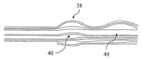
目的物がオーバラップしているときであっても、目的物を分離して画像化し得る十分な解像度と通常考えられる程度でなくとも目的物を分離できるキー原理として、目的物の動作を理解できる。このことは、エコー配置のプロセスが線形であるという観察から始まる。一つの目的物からのエコーは別の目的物のエコーの上に重ね合わせされ、全体画像を、シーン内の種々の反射体の動作から始まる“透過的な”インパルス応答画像の和とする。よって、本発明の好適な実施形態は、多数フレーム透過モーション評価を用いる。このことを可視化する簡単な方法は、相互の上に敷かれた透過シート上にプリントされた異なるテキストを考察することである。シートが相互に静止していれば、どのテキストも読むことが困難若しくは不可能である。しかしながら、それらシートが相互に動いていれば、ずっと読むことが容易である。 Even when the objects overlap, it is possible to understand the operation of the object as a key principle that can separate the object even if it is not of a resolution that is normally considered to be sufficient resolution to separate and image the object. . This begins with the observation that the process of echo placement is linear. The echoes from one object are superimposed on the echoes of another object, and the overall image is the sum of “transparent” impulse response images starting from the movement of the various reflectors in the scene. Thus, the preferred embodiment of the present invention uses multiple frame transmission motion estimation. A simple way to visualize this is to consider different texts printed on transparent sheets laid on top of each other. If the sheets are stationary with respect to each other, it is difficult or impossible to read any text. However, it is much easier to read if the sheets move relative to each other.
モーションを用いて、近接離隔する若しくはオーバラップする目的物を分離するという概念は、時間領域でより高い解像度を活用することにより、空間領域で貧弱な解像度を強化することとして、理解され得る。 The concept of using motion to separate closely spaced or overlapping objects can be understood as enhancing poor resolution in the spatial domain by exploiting higher resolution in the time domain.
更なる形態から精査して、本発明は、一つ若しくはそれ以上の他の目的物が存在する画像フィールド内の目的物を追跡する方法において、
エネルギを上記画像フィールド内に送信するステップと、
上記画像フィールドから反射されたエネルギを受信するステップと、
連続する時間間隔で一連のインパルス応答を計算するステップと、
連続動作に対応する上記インパルス応答のサブセットを選択するステップと
を含む方法を与える。本発明は、その方法を実行するように構成された装置にまで及び、上記計算するステップと上記選択するステップとを実行するように構成されたコンピュータソフトウエアプロダクトにまで及ぶ。
In scrutiny from further aspects, the present invention provides a method for tracking an object in an image field in which one or more other objects are present.
Transmitting energy into the image field;
Receiving energy reflected from the image field;
Calculating a series of impulse responses at successive time intervals;
Selecting a subset of the impulse response corresponding to continuous motion. The invention extends to an apparatus configured to perform the method and to a computer software product configured to perform the calculating step and the selecting step.
送信されるエネルギは、(規則的に、若しくは不規則的に)間欠的であり、例えば、個別のパルス、パルストレーン、チャープ等の形態であり、又は、連続的である。 The transmitted energy is intermittent (regularly or irregularly), for example in the form of individual pulses, pulse trains, chirps, etc., or continuous.
このことが意味するところは、少なくとも好適な実施形態では、他のケースよりも、本発明により、より少ないセンサで多数の目的物の移動を追跡することができる、ということである。本発明に係る技術により、目的物のオーバラップにも拘らず、必要な完全な画像無しで、実効的にモーションを検出できる。第1の目的物の動作に対応するインパルス応答画像内のパターンは、分離して識別可能であり、インパルス応答画像のサブセット(例えば、ライン)として分離することができる。このことは、合成画像を、独立のモーションに対応する独立の層に実効的に分解することである。もちろん、目的物に対するパターンがオーバラップする場合、上述の画像“サブセット”の一部は、他の目的物のモーションに対する対応する“サブセット”にも属する。 This means that, at least in the preferred embodiment, the present invention can track the movement of a large number of objects with fewer sensors than in other cases. With the technology according to the present invention, it is possible to effectively detect a motion without a necessary complete image despite the overlap of objects. The patterns in the impulse response image corresponding to the operation of the first object can be separated and identified and separated as a subset (eg, line) of the impulse response image. This is effectively decomposing the composite image into independent layers corresponding to independent motions. Of course, if the patterns for the objects overlap, some of the above-mentioned image “subsets” also belong to corresponding “subsets” for the motion of other objects.
物理的原理の利用の例をインパルス応答画像に適用して、追跡される目的物が手の指であるならば、所定の速度及び/又は加速度以下で、連続的な移動のみを考察することにより、移動についてインテリジェントな評価を為すことができる。これは、インパルス応答画像内のラインの特性に翻訳され得る。ラインは連続であり、しきい値以下の勾配を有し、またしきい値以下の曲率を有することがある。この最後の基準は、最良適合の線形セクションに対する勾配の最大限の変化として、適用され得る。もちろん、一つ以上の送信器受信器のペアを有するシステム内の異なる“チャネル”の各々に対して、異なる勾配及び異なるしきい値が適用され得る。 By applying an example of the use of physical principles to an impulse response image, if the object being tracked is a finger of a hand, consider only continuous movements below a given velocity and / or acceleration , Make intelligent assessments of travel. This can be translated into a characteristic of the line in the impulse response image. The line is continuous, has a slope below the threshold, and may have a curvature below the threshold. This last criterion can be applied as the maximum change in slope for the best-fit linear section. Of course, different slopes and different thresholds may be applied to each of the different “channels” in a system having one or more transmitter-receiver pairs.
インパルス応答画像が分析されて目的物のモーションを判別する、多くの方法がある。ある状況では、相対的に大まかな分析が十分であることもある。例えば、システムは、変化の正確な性質、若しくは変化を生じた移動を判別する必要無く、しきい値以上の、インパルス応答における、若しくはその所定の部分における集合的な変化を検出するように、構成されている。このことに関して一つだけ例をとると、所与の期間に渡りインパルス応答が10%以上変化すれば、それは移動として解釈される、と判別され得る。 There are many ways in which the impulse response image is analyzed to determine the motion of the object. In some situations, a relatively rough analysis may be sufficient. For example, the system can be configured to detect collective changes in the impulse response, or in certain parts thereof, above the threshold without having to determine the exact nature of the change or the movement that caused the change. Has been. Taking only one example in this regard, it can be determined that if the impulse response changes by more than 10% over a given period, it is interpreted as a movement.
より識別性のある分析が要求されるならば、利用可能な多数の様々なアプローチが存在する。例えば、どのセットのフィルタも、又は、線形若しくは非線形変換も、利用可能であり、以下のものを含むがそれらに限定されない。曲線−線形フィルタ、ハフ変換、ランダム変換、ピタウ(pi−tau)変換、及び、フーリエ変換若しくは非整数次フーリエ変換、これらはインパルス応答画像全体若しくはそれらの部分に適用される。別の形態では、上記画像のサブブロックを基本画像ブロックのセットに適合する、若しくは、上記画像のサブブロックを基本画像ブロックのセットにスライドすることにより、突起アプローチは採用され得る。 There are many different approaches available if more discriminatory analysis is required. For example, any set of filters, or linear or non-linear transformations can be used, including but not limited to: Curve-linear filters, Hough transforms, random transforms, pi-tau transforms, and Fourier transforms or non-integer order Fourier transforms, which are applied to the entire impulse response image or parts thereof. In another form, a protrusion approach may be employed by fitting the image sub-blocks to a set of basic image blocks, or by sliding the image sub-blocks into a set of basic image blocks.
別の形態では、順応フィルタ、若しくは他の適切な数学的技術が、2つ若しくはそれ以上の目的物のモーションに対応する2つ若しくはそれ以上の層を“分解する”ために、適用され得る。 In another form, an adaptive filter, or other suitable mathematical technique, can be applied to “decompose” two or more layers corresponding to the motion of two or more objects.
更に別の形態では、画像は、関数データ分析を用いて表され得る。更に別の形態では、インパルス応答コラムのシフト及び移動平均を含む、フーリエ変換領域、非整数次フーリエ変換領域、若しくは時間領域で、フィルタが実現され得る。ある実施形態では、アップサンプリング、ダウンサンプリング、若しくはリサンプリングにより、インパルス応答画像が変換され得る。ある実施形態では、インパルス応答領域にコンボリューションする前に、受信した信号(即ち、“生の”信号領域)に、フィルタが適用され得る。 In yet another form, the image may be represented using functional data analysis. In yet another form, the filter may be implemented in the Fourier transform domain, non-integer order Fourier transform domain, or time domain, including impulse response column shifts and moving averages. In some embodiments, the impulse response image may be transformed by upsampling, downsampling, or resampling. In some embodiments, a filter may be applied to the received signal (ie, the “raw” signal domain) before convolving to the impulse response domain.
複数のそのような分析は単一のインパルス応答画像に対して組み合わせ可能であり、例えば、一つ若しくはそれ以上のフィルタがインパルス応答画像に適用される。結果としてフィルタされた画像は、ウエーブレット変換により変換される。一つ若しくはそれ以上の更なるフィルタが変換された画像に適用される。逆変換が適用される。そして一つ若しくはそれ以上の更なるフィルタがインパルス応答画像領域に適用される。 Multiple such analyzes can be combined for a single impulse response image, for example, one or more filters are applied to the impulse response image. The resulting filtered image is transformed by wavelet transformation. One or more additional filters are applied to the transformed image. Inverse transformation is applied. One or more additional filters are then applied to the impulse response image region.
しかしながら、目的物の静止状態及びモーションは、インパルス応答画像から、より速やかに明白であるから、例えば、計算の簡素性の意味で、(変換された領域内ではなく)インパルス応答画像内で或る分析を行なうことは、有利である、ということを、出願人は理解した。 However, the stationary state and motion of the object are more quickly apparent from the impulse response image, so for example in the impulse response image (rather than in the transformed region) in the sense of computational simplicity. Applicants have understood that it is advantageous to perform the analysis.
方法の好適な実施形態の一つの設定は、一つ若しくはそれ以上のラインフィルタを画像に適用することを含む。ラインフィルタは、画像の残部に対して所与のライン上に配置する画像の部分を強化するアルゴリズムである。これは、それら部分の元の強度からそれら部分を強化すること、他の部分の強度を減少すること、若しくはその二つを組み合わせることにより、達成され得る。ラインフィルタの更なる利点は、マトリクス内に“悪いコラム”を発生させ、従来の飛行時間追跡システムを混乱させるような、チャネルノイズのスプリアスの、一時的バーストの効果を減少するのに、効果的であることである。 One setting of a preferred embodiment of the method includes applying one or more line filters to the image. A line filter is an algorithm that enhances the portion of an image that is placed on a given line relative to the rest of the image. This can be accomplished by strengthening the parts from their original strength, reducing the strength of the other parts, or a combination of the two. A further advantage of the line filter is that it is effective in reducing the effects of temporary bursts of channel noise spurs that can cause “bad columns” in the matrix and disrupt conventional time-of-flight tracking systems. It is to be.
実施形態の好適な設定では、直線フィルタが採用される。これらは、比較的簡単な計算を与えるという利点を有するが、にもかかわらず、万一必要であれば順次の曲線適合を介して非線形モーションを概算するのに利用され得る。例えば、特定の動きのみを探索するシステムのために、単一のフィルタを利用することができるが、複数の異なるフィルタが適用されるのが好ましい。個々のフィルタにより鉄製される結果は、比較されて“勝利者”、即ち、所与の領域全体で若しくは所与の領域の範囲内で、最も強い結果を与えるものを、判別できる。しきい値結果の強度は適用され、例えば、対象の目的物が存在しない場合に誤り整合を回避できる。 In a preferred setting of the embodiment, a linear filter is employed. These have the advantage of providing relatively simple calculations, but can nevertheless be used to approximate nonlinear motion via sequential curve fitting if necessary. For example, a single filter can be utilized for a system that searches only for specific movements, but preferably a plurality of different filters are applied. The results made of iron by the individual filters can be compared to determine the “winner”, ie, the one that gives the strongest result over a given area or within a given area. The intensity of the threshold result is applied, and for example, error matching can be avoided when the target object does not exist.
ラインフィルタマスクは、その端部にてロールオフを伴って構成され、即ち、シャープな境界ではなく、ラインに垂直な方向(即ち、水平ラインであれば上と下)と、ラインの端部から離れる方向の両方で、ラインの中心から離れて差異エンハンスメントの減少があるのが望ましい。 The line filter mask is configured with a roll-off at its end, i.e., not a sharp boundary, but in a direction perpendicular to the line (i.e., up and down for a horizontal line) and away from the end of the line. In both cases, it is desirable to have a decrease in difference enhancement away from the center of the line.
合計や平均を含む、簡単なラインフィルタは、画像への線形操作として理解され得る。しかしながら、合計や平均に先立って、ノイズピクセルが他のピクセルと汚すことを回避するために、ノイズの可能性の高いコラム、ロー若しくはピクセルを除去する適応異常値フィルタを備えることによりパフォーマンスを向上するなどの、フィルタに対する簡素な若しくは複雑な非線形の改良を、想定することができる。 Simple line filters, including sums and averages, can be understood as linear operations on the image. However, prior to summing and averaging, performance is improved by having an adaptive outlier filter that removes columns, rows, or pixels with a high probability of noise to avoid smearing noisy pixels with other pixels. Simple or complex non-linear improvements to the filter can be envisaged.
更に若しくは一方で、エッジフィルタが利用される。線形バンドの厚さの範囲内のどこでも整合する、ラインフィルタとは対照的に、エッジフィルタはそのバンドの2つの境界の一つ若しくは両方にのみ整合する。よって、エッジフィルタは、概略、高い大きさの領域と低い大きさ(例えば、ゼロ近く)の領域(インパルス応答の絶対値の大きさ)の近傍を要求する。エッジフィルタは水平でもよいが、所定の角度があるのが好ましい。所定のタイプのモーションの早期の判別で、通常有用である。インパルス応答画像の範囲内のラインのエッジのみに強く整合するからである。これは目的物の前面若しくは背面の検出に対応しうるのであり、例えば、人間の指を位置付けるのに有効に用いられ得る。 In addition or on the other hand, an edge filter is used. In contrast to a line filter that matches anywhere within the thickness of a linear band, an edge filter only matches one or both of the two boundaries of the band. Therefore, the edge filter generally requires a vicinity of a high-size area and a low-size (for example, near zero) area (the magnitude of the absolute value of the impulse response). The edge filter may be horizontal, but preferably has a predetermined angle. It is usually useful for early discrimination of a given type of motion. This is because it strongly matches only the edge of the line within the range of the impulse response image. This can correspond to detection of the front or back of the object, and can be used effectively, for example, to position a human finger.
更に若しくは一方で、フィルタマスクのコラムは送信信号の帯域幅を表すシンク信号でコンボルーションされ得る。このことにより、近傍のラインからの情報が組み合わされ、これにより、より可視的なラインが抽出される。 Additionally or alternatively, the filter mask column can be convoluted with a sync signal representing the bandwidth of the transmitted signal. This combines information from nearby lines, thereby extracting more visible lines.
更に若しくは一方で、目的物のモーションの位相、方向、及び振幅の両方を捕らえる複素フィルタも利用され得る。 In addition or on the other hand, complex filters that capture both the phase, direction, and amplitude of the motion of the object may also be utilized.
ある状況では、フィルタマスクがインパルス応答画像内の複数のラインを組み合わせて、より少ないライン、例えば、単一のラインを与えることもできる。例えば、対象の目的物が、強い反射体、例えば、コンピュータスクリーン近くで動いているならば、インパルス応答画像は、目的物から直接反射する信号と、夫々スクリーンも介して反射した信号とに対応する、類似のラインを含む。 In certain situations, the filter mask may combine multiple lines in the impulse response image to give fewer lines, eg, a single line. For example, if the target object is moving near a strong reflector, eg, a computer screen, the impulse response image corresponds to a signal reflected directly from the object and a signal reflected through the screen, respectively. , Including similar lines.
ある利用例では大量の計算資源を要求する2次元フィルタマスクを計算することは、必ずしも必要ではなく、例えば、別のものが、ローリング平均、有限インパルス応答フィルタ、若しくはサブバンドコーディングラフィックに基づくフィルタを利用する、ということを、出願人は更に理解した。当然のことながら、そのようなフィルタが、二つ若しくはそれ以上の連続的なインパルス応答からの情報に作用し得る。 In some applications, it is not always necessary to calculate a two-dimensional filter mask that requires a large amount of computational resources, for example, another can be a rolling average, a finite impulse response filter, or a filter based on a subband chordal graphic. The applicant further understood that it would use it. Of course, such a filter can operate on information from two or more successive impulse responses.
更に、直線フィルタを利用することは本質的ではない。例えば、特定の曲線に対応するフィルタ、即ち、曲線−線形フィルタが、代わりに若しくは加えて、適用され得る。更に別途、特に、複数の移動する目的物のケースで、例えば、ジェスチャ認識で、特定の動作を探索するために、より複雑なマスクが用いられてもよい。このことの例は、往復する目的物の動作、例えば、手を振ること、を検出する正弦関数フィルタである。 Furthermore, it is not essential to use a linear filter. For example, a filter corresponding to a specific curve, ie a curve-linear filter, may be applied instead or in addition. In addition, more complex masks may be used to search for specific movements, particularly in the case of multiple moving objects, for example with gesture recognition. An example of this is a sine function filter that detects the movement of a reciprocating object, such as waving.
しかしながら、比較的複雑な形状のマスクを用いる代わりに、インパルス応答画像内のパターンは、簡単なフィルタがインパルス応答に適合する順番を記録することにより、判別され得る、ということを出願人は理解した。このことにより、ジェスチャなどの、特定タイプの動作が、ジェスチャに関する特定の位置、方向若しくは速度に拘らず、インパルス応答画像内の対応するパターンにより、検出され得る。よって、好適な実施形態の設定は、インパルス応答画像の夫々の部分に適合するフィルタのシーケンスを記録するステップ、及び、上記シーケンスを一つ若しくはそれ以上の所定のシーケンスと比較して、例えば、特定のジェスチャに対応する、インパルス応答内の特徴パターンを識別するステップを、含む。所定のシーケンスは、特定の所定のフィルタを含み得るが、正しいセットからのフィルタがシーケンスを満足し得るフィルタのセットのシーケンスを含んでもよい。 However, the applicant has understood that instead of using a relatively complex shaped mask, the pattern in the impulse response image can be determined by recording the order in which simple filters fit the impulse response. . This allows a specific type of motion, such as a gesture, to be detected by the corresponding pattern in the impulse response image, regardless of the specific position, direction or velocity with respect to the gesture. Thus, the preferred embodiment settings include the steps of recording a sequence of filters that fit respective portions of the impulse response image, and comparing the sequence to one or more predetermined sequences, eg, specifying Identifying a feature pattern in the impulse response that corresponds to the gesture. The predetermined sequence may include a specific predetermined filter, but may also include a sequence of sets of filters in which filters from the correct set may satisfy the sequence.
一つの例では、水平フィルタが続き、更には下方スロープフィルタが続く、上方スロープフィルタを含む所与の一連のフィルタにより、正のフィルタが適合するならば、振動などの通常のモーションが推測され得る。この技術は、例えば、振り若しくは招きジェスチャの、リズミカルな小刻みな動きである、一つ若しくはそれ以上の人間の指を検出するのに、利用され得る。そのような特定のジェスチャを検出して、接続された電子システムはジェスチャに対応する特定の作用を行なうことができる。適合したものから比較的簡単なフィルタのシーケンスを識別するこのアプローチは、正弦関数ラインフィルタなどの、一つの複雑なフィルタを適用するよりも、通常、計算上廉価である。特に、曲線を追跡することのみに必要であるラインフィルタを適用することに加えて、このことが為される場合は、そうである。例えば、正弦関数ラインフィルタは、トレース内の変動の周波数の狭い範囲にのみ整合するので、より多用途でもある。このアプローチは、ラインフィルタ、エッジフィルタ、目的物に関する方向の情報を捕らえる他のフィルタ、又はこれらの一部若しくは全ての組み合わせによって、適用され得る。 In one example, a given series of filters, including an upper slope filter followed by a horizontal filter, followed by a lower slope filter, normal motion such as vibration can be inferred if the positive filter fits. . This technique can be used to detect one or more human fingers, for example, rhythmic tiny movements of a swing or beckoning gesture. Upon detecting such a specific gesture, the connected electronic system can perform a specific action corresponding to the gesture. This approach of identifying a relatively simple sequence of filters from the fit is usually less computationally expensive than applying a single complex filter, such as a sinusoidal line filter. In particular, if this is done, in addition to applying a line filter that is only needed to track the curve. For example, sinusoidal line filters are more versatile because they only match a narrow range of frequencies of variation within the trace. This approach can be applied by line filters, edge filters, other filters that capture directional information about the object, or some or all combinations thereof.
概略、フィルタマスクの形状は、様々に変化し得る。例えば、特定のラインを強化することに加えて、又は、その代わりに、例えば、対象でない、ノイズ、干渉、若しくは移動に関する周知の、若しくは予め識別されたソースに対応する、インパルス応答画像の特定領域を抑圧する、若しくはより強く抑圧するのに、用いられ得る。 In general, the shape of the filter mask can vary. For example, in addition to or instead of enhancing a specific line, a specific region of the impulse response image, eg corresponding to a known or pre-identified source of noise, interference or movement that is not of interest Can be used to suppress or more strongly suppress.
その最も簡単な実施形態では、本発明は、単一の送信器及び単一のセンサ/受信器のみを用いる単一の若しくは多数の本体の存在若しくは動作に関する有用な情報を与えるのに、用いられ得る。しかしながら、複数の送信器及び/又は複数の受信器が設けられてもよい。 In its simplest embodiment, the present invention is used to provide useful information regarding the presence or operation of a single or multiple bodies using only a single transmitter and a single sensor / receiver. obtain. However, multiple transmitters and / or multiple receivers may be provided.
本発明のある実施形態は、単一の送信器及び受信器のペアのみを利用し得る。これらは、物理的に独立したトランスデューサであるか、若しくは、単一の及び/又はトランスデューサにより与えられる。しかしながら、少なくとも或る実施形態では、複数の受信器が与えられる。インパルス応答画像が個々のセンサに対して構築されるのが、好ましい。一つ若しくはそれ以上の“勝ち”ラインは、これら画像の各々から判別可能であり、何らかの方法で組み合わされたラインは2D若しくは3D空間で全体ラインを与える。しかしながら、個々の特定のセンサチャネルに対する共通速度の推測から適合されるフィルタ、例えば、ラインフィルタが、適用される。言い換えれば、システムは、前の軌道及び物理的ルールと一致する目的物に対する速度を推測し、個々のセンサチャネルに対するライン(若しくは他の)フィルタのセットに、この速度の推測を変換するのが、好ましい。個々のセンサチャネルは、所与の軌道に対して異なるフィルタを要求する。目的物に対するセンサの様々な位置に依存して、インパルス応答画像の一つのコラムと次のコラムの間に、夫々が、僅かに異なる変化を与えるためである。 Certain embodiments of the invention may utilize only a single transmitter and receiver pair. These are either physically independent transducers or are provided by a single and / or transducer. However, at least in some embodiments, multiple receivers are provided. It is preferred that impulse response images are constructed for individual sensors. One or more “winning” lines can be discriminated from each of these images, and lines combined in some way give an overall line in 2D or 3D space. However, a filter adapted from an estimate of the common speed for each particular sensor channel, for example a line filter, is applied. In other words, the system estimates the velocity for objects that match the previous trajectory and physical rules, and translates this velocity estimate into a set of line (or other) filters for the individual sensor channels. preferable. Each sensor channel requires a different filter for a given trajectory. This is because, depending on the various positions of the sensor relative to the object, each gives a slightly different change between one column and the next column of the impulse response image.
少なくとも或る好適な実施形態では、複数の送信器が利用される。好適な実施形態の一つのうちの設定では、個々のセンサに対する送信信号に対して、異なる遅延が加えられる。他のセンサに対する位置に依存する、個々のセンサに対する適切な時間遅延により、例えば、全方向性送信信号でも、送信信号の狭い“ビーム”を共通して送信でき、よってビームの経路の目的物のみが検出され若しくは追跡される。このことは、モバイルのバッテリ電源デバイスの場合に重要である、全体より少ない送信器パワーが用いられ得ることにつき利点がある。このことの理由は、ビーム形成はより大きい選択性をもたらし、そのため、所与の最小限S/N比を達成するのに全体より少ないパワーが要求されるに過ぎないことである。 In at least some preferred embodiments, multiple transmitters are utilized. In the setting of one of the preferred embodiments, different delays are added to the transmitted signals for the individual sensors. With appropriate time delays for individual sensors, depending on the position relative to other sensors, for example, even omnidirectional transmission signals can transmit a narrow “beam” of the transmission signal in common, so only the target of the beam path Is detected or tracked. This has the advantage that less transmitter power can be used, which is important for mobile battery powered devices. The reason for this is that beamforming provides greater selectivity, so less power is required overall to achieve a given minimum S / N ratio.
同様の概念が、複数のセンサに適用され得る。よって、複数のセンサを含む好適な実施形態では、人為的な遅延が、少なくとも一部のセンサのインパルス応答に加えられ、よってシステムは、センサの位置及び夫々の時間遅延により規定される対応するビームの範囲内から発するエコーにのみ、感受性が有ることになる。ビームの方向は、適用される遅延のパターンを変化することにより、勿論整合的に変化し得る。その集束の属性は、適切な重みを適用することによっても変わり得る。ビームの方向は、追跡される目的物の予測されたモーションに基づいて、決定されるのが好ましい。前述のように、そのような予測は、前の軌道と、動作の連続性及び最大限の加速度に基づく簡単な物理法則とに、基づく。多数の送信器の場合のように、そのようなビーム形成により、対象でない方向から生じる信号を効果的に抑圧でき、よって、対象の目的物のより正確な追跡が可能になる。 Similar concepts can be applied to multiple sensors. Thus, in a preferred embodiment comprising a plurality of sensors, an artificial delay is added to the impulse response of at least some sensors, so that the system can detect the corresponding beam defined by the position of the sensor and the respective time delay. Only echoes originating from within the range are sensitive. The direction of the beam can of course be changed consistently by changing the pattern of delay applied. The focusing attribute can also be changed by applying appropriate weights. The beam direction is preferably determined based on the predicted motion of the tracked object. As mentioned above, such predictions are based on previous trajectories and simple physical laws based on motion continuity and maximum acceleration. As in the case of multiple transmitters, such beamforming can effectively suppress signals originating from non-target directions, thus allowing more accurate tracking of target objects.
例えば、比較的低い解像度で十分であるような、実施形態では、本発明に係る送信信号は、非送信の期間が散在された離散インパルスを含み得る。例えば、より大きい解像度が要求される、他の実施形態では、連続送信が利用される。これは、時間スロットの期間も、別の期間も、その多数を規則正しく繰り返す。当然ながら、連続送信が用いられる場合、時間スロットは、送信される物理信号に関係なく、純粋に理論的に構築され得る。このような場合、“時間スロット”は、インパルス応答画像が構築されるとき、インパルス応答を特定のサンプリング間隔に関連付けるラベルに過ぎない。 For example, in embodiments where a relatively low resolution is sufficient, the transmitted signal according to the present invention may include discrete impulses interspersed with non-transmission periods. For example, in other embodiments where greater resolution is required, continuous transmission is utilized. This regularly repeats many of the time slot periods and other periods. Of course, when continuous transmission is used, time slots can be constructed purely theoretically, regardless of the physical signal transmitted. In such a case, a “time slot” is just a label that associates the impulse response with a particular sampling interval when the impulse response image is constructed.
インパルス応答は、適切な技術を用いて計算され得る。例えば、離散パルスが送信されるならば、信号が周知の技術により分離され得る限りにおいてのみ、エコーが干渉しない若しくは干渉する、十分な時間がパルス間に存在することがある。パルスがより近接した上で離隔する場合、若しくは連続送信が用いられる場合、WO2006/067436(特許文献3)で開示される相互相関若しくは連続反転技術などの、他の方法が利用され得る。 The impulse response can be calculated using a suitable technique. For example, if discrete pulses are transmitted, there may be sufficient time between the pulses that the echoes do not interfere or interfere as long as the signals can be separated by known techniques. If the pulses are spaced closer together, or if continuous transmission is used, other methods such as cross-correlation or continuous inversion techniques disclosed in WO 2006/067436 may be utilized.
マルチフレーム若しくはマルチポイントで利用するためのインパルス応答画像の利用により、モーション評価は、それ自体で新規性及び進歩性があると考えられ、よって、更なる形態から精査すると、本発明は、画像フィールド内の一つ若しくはそれ以上の目的物の動作を判別する方法において、
連続の若しくは非連続の送信信号を送信するステップと、
複数の受信信号を受信するステップと、
上記送信信号と上記受信信号を利用して、複数のチャネルインパルス応答を判別するステップと、
夫々の時間間隔に対するインパルス応答を相互に近接させて、インパルス応答のマトリクスを規定するステップと、
上記目的物の一つの動作に対応するパターンを上記マトリクスから分離するステップと
を含む方法を、提供する。
Through the use of impulse response images for multi-frame or multi-point use, motion estimation is considered novel and inventive in itself, so that, upon further examination from a further form, the present invention A method for determining the behavior of one or more objects
Transmitting a continuous or non-continuous transmission signal;
Receiving a plurality of received signals;
Determining a plurality of channel impulse responses using the transmitted signal and the received signal;
Defining the matrix of impulse responses by bringing the impulse responses for each time interval close to each other;
Separating a pattern corresponding to one operation of the object from the matrix.
本発明は、画像フィールド内で一つ若しくはそれ以上の目的物の動作を判別する装置において、
連続の若しくは非連続の送信信号を送信するように構成された送信手段と、
複数の受信信号を受信するように構成された受信手段と、
上記送信信号と上記受信信号を利用して、複数のチャネルインパルス応答を判別し、近接する時間フレームに対するインパルス応答を相互に近接させて、インパルス応答のマトリクスを規定し、更に、上記目的物の一つの動作に対応するパターンを上記マトリクスから分離するように、構成された処理手段と
を含む装置にまで、及ぶ。
The present invention provides an apparatus for discriminating the operation of one or more objects in an image field.
Transmission means configured to transmit a continuous or non-continuous transmission signal;
Receiving means configured to receive a plurality of received signals;
A plurality of channel impulse responses are discriminated using the transmission signal and the reception signal, impulse responses for adjacent time frames are made close to each other, a matrix of impulse responses is defined, Extends to an apparatus including processing means configured to separate a pattern corresponding to one operation from the matrix.
本発明は、コンピュータ上で稼動する際、画像フィールド内で一つ若しくはそれ以上の目的物の動作を判別するように構成されたコンピュータソフトウエアプロダクト、及びそれを坦持するキャリアにおいて、
ソフトウエアは、
連続の若しくは非連続の送信信号と複数の受信信号とに対するインプットを有し、
更に、
上記送信信号と上記受信信号を利用して、複数のチャネルインパルス応答を判別し、近接する時間フレームに対するインパルス応答を相互に近接させて、インパルス応答のマトリクスを規定し、更に、上記目的物の一つの動作に対応するパターンを上記マトリクスから分離するように、構成されたロジックを含む、
コンピュータソフトウエア、及びそれを坦持するキャリアにまで、及ぶ。
The present invention relates to a computer software product configured to determine the operation of one or more objects in an image field when operating on a computer, and a carrier carrying the same.
The software
Having inputs for continuous or non-continuous transmit signals and multiple receive signals;
Furthermore,
A plurality of channel impulse responses are discriminated using the transmission signal and the reception signal, impulse responses for adjacent time frames are made close to each other, a matrix of impulse responses is defined, Including logic configured to separate a pattern corresponding to one operation from the matrix;
It extends to computer software and carriers that carry it.
本発明の全ての前述の形態によると、インパルス応答情報は、既に説明したように、時間領域でのみ分析され得る。しかしながら、更に若しくは一方で、本発明の或る実施形態では、インパルス応答は周波数領域で分析される。このことは、インパルス応答の少なくともいくつかに関して、フーリエ変換、好ましくは高速フーリエ変換を実施することにより、達成される。出願人は、このような周波数領域分析から更なる情報が得られることを理解した。例えば、目的物の回転運動と並進運動との間で区別をすることができる。回転運動は振幅スペクトラムのゼロポイント内に(相殺的干渉に起因する)シフトを生じるのに対し、並進運動はそうではないからである。よって、好適な実施形態は、周波数領域での振幅スペクトラクを分析することを含む。 According to all the aforementioned aspects of the invention, the impulse response information can only be analyzed in the time domain, as already explained. However, in addition or on the other hand, in some embodiments of the invention, the impulse response is analyzed in the frequency domain. This is achieved by performing a Fourier transform, preferably a fast Fourier transform, on at least some of the impulse responses. Applicants have understood that further information can be obtained from such frequency domain analysis. For example, a distinction can be made between rotational and translational movements of the object. This is because rotational motion causes a shift (due to destructive interference) within the zero point of the amplitude spectrum, whereas translational motion is not. Thus, the preferred embodiment includes analyzing the amplitude spectrum in the frequency domain.
更に、絶対エネルギレベルは送信器/受信器への距離に依存するのであるが、並進運動する単一の目的物に対して周波数スペクトラムの形状(個々の周波数の相対的量)は一定のままであることが、分かった。しかしながら、多数の目的物が運動していれば、周波数スペクトラムの形状は経時的に変化する。この情報は、例えば、より正確に若しくは効果的に時間領域内で運動をいかに分析するかを決定するのに利用され得る。このように周波数スペクトラムでの経時的な変化が判別される。 Furthermore, while the absolute energy level depends on the distance to the transmitter / receiver, the shape of the frequency spectrum (the relative amount of individual frequencies) remains constant for a single object that translates. I knew that there was. However, if a large number of objects are moving, the shape of the frequency spectrum changes over time. This information can be used, for example, to determine how to analyze motion in the time domain more accurately or effectively. In this way, a change with time in the frequency spectrum is determined.
画像フィールドの目的物が、観察の時間ウインドウの間にサイズ若しくは形状において変わるならば、その周波数スペクトラムは変化する。例えば、サイズの変化は、周波数におけるシフトを生じる。このことは、例えば、個々の指の位置を詳細に追跡すること無く、閉じた構成から開いた構成へ手が開くことを検出するための、簡素なアルゴリズムで利用され得る。 If the object of the image field changes in size or shape during the observation time window, its frequency spectrum will change. For example, a change in size causes a shift in frequency. This can be used, for example, with a simple algorithm to detect a hand opening from a closed configuration to an open configuration without closely tracking the position of individual fingers.
目的物がその形状を変化するならば、インパルス応答画像の対応する部分におけるその対応する周波数表現も変化する。フーリエ変換を利用する周波数情報の応用例は、目的物はその形状を変えつつあるもしくはその形状を変えていた、ということを、単に検出し得るということである。親指を突き出す若しくは引っ込めるなど、目的物がその形状を変化するならば、このことは、インパルス応答の対応する部分の周波数スペクトラム及び位相を変化させる。次にこのことは、コンピュータが特定の作用を行なうコマンドとして、例えば、マウスクリックとして作用を取り扱うコマンドとして、捉えられ得る。このことは、インパルス応答の変化のしきい値レベルが検出される、若しくは適切なフィルタを用いて“ヒット”のシーケンスが検出される、時間領域での、前述の分析の周波数領域のコロラリである。 If the object changes its shape, its corresponding frequency representation in the corresponding part of the impulse response image also changes. An application example of frequency information using Fourier transform is that it can simply detect that the object is changing its shape or changing its shape. If the object changes its shape, such as sticking out or retracting the thumb, this will change the frequency spectrum and phase of the corresponding part of the impulse response. This can then be viewed as a command that the computer performs a specific action, for example, a command that handles the action as a mouse click. This is the frequency domain of the above analysis in the time domain, where the threshold level of change in impulse response is detected, or a sequence of “hits” is detected using a suitable filter. .
時間領域の分析と概略同様に、目的物のサイズ、形状若しくは絶対位置を知ること無く、周波数領域の分析を利用して、特定タイプのモーションを識別すること、及び/又は、目的物を追跡することが、可能である。このことは、ポイント毎の“決定性”の追跡アプローチとは対照的に、“確率的”追跡アプローチとして。理解され得る。 Similar to time domain analysis, use frequency domain analysis to identify specific types of motion and / or track objects without knowing the size, shape or absolute position of the object. Is possible. This is a “stochastic” tracking approach as opposed to a point-by-point “deterministic” tracking approach. Can be understood.
周波数領域の分析は、それ自体で新規性及び進歩性を有すると考えられ、よって別の形態から精査すると、本発明は、目的物の所定の動作を識別する方法において、
送信信号を送信するステップと、
第1の時間間隔の間に第1の受信信号を受信するステップと、
上記第1の受信信号の第1の周波数構成を判別するステップと、
第2の時間間隔の間に第2の受信信号を受信するステップと、
上記第2の受信信号の第2の周波数構成を判別するステップと、
上記第1の周波数構成と上記第2の周波数構成の間に所定の差異が存在するかどうか判別するステップと
を含む方法を、提供する。
Frequency domain analysis is considered to be novel and inventive in its own right, and thus, when scrutinized from another form, the present invention provides a method for identifying a predetermined behavior of an object:
Transmitting a transmission signal;
Receiving a first received signal during a first time interval;
Determining a first frequency configuration of the first received signal;
Receiving a second received signal during a second time interval;
Determining a second frequency configuration of the second received signal;
Determining whether there is a predetermined difference between the first frequency configuration and the second frequency configuration.
本発明は、目的物の所定の動作を識別する装置において、
送信信号を送信するように構成された送信手段と、
第1の時間間隔の間に第1の受信信号を受信し、第2の時間間隔の間に第2の受信信号を受信するように構成された受信手段と、
上記第1の受信信号の第1の周波数構成を判別し、上記第2の受信信号の第2の周波数構成を判別し、更に、上記第1の周波数構成と上記第2の周波数構成の間に所定の差異が存在するかどうか判別するように、構成された処理手段と
を含む装置にまで、及ぶ。
The present invention provides an apparatus for identifying a predetermined operation of an object,
A transmission means configured to transmit a transmission signal;
Receiving means configured to receive a first received signal during a first time interval and receive a second received signal during a second time interval;
Determining a first frequency configuration of the first received signal; determining a second frequency configuration of the second received signal; and further, between the first frequency configuration and the second frequency configuration. Extends to an apparatus that includes processing means configured to determine whether a predetermined difference exists.
本発明は更に、コンピュータ上で稼動する際、目的物の所定の動作を識別するように構成されたコンピュータソフトウエアプロダクト、及びそれを坦持するキャリアにおいて、
ソフトウエアは、
第1の時間間隔の間の第1の受信信号と、第2の時間間隔の間の第2の受信信号とに対するインプットを有し、
更に、
上記第1の受信信号の第1の周波数構成を判別し、上記第2の受信信号の第2の周波数構成を判別し、更に、上記第1の周波数構成と上記第2の周波数構成の間に所定の差異が存在するかどうか判別するように、構成されたロジックを含む
コンピュータソフトウエアプロダクト、及びそれを坦持するキャリアにまで、及ぶ。
The present invention further includes a computer software product configured to identify a predetermined operation of an object when operating on a computer, and a carrier that carries the computer software product.
The software
Having inputs to a first received signal during a first time interval and a second received signal during a second time interval;
Furthermore,
Determining a first frequency configuration of the first received signal; determining a second frequency configuration of the second received signal; and further, between the first frequency configuration and the second frequency configuration. It extends to computer software products that include structured logic and carriers that carry them to determine whether a given difference exists.
上記の概念は、共通して収集され分析される、多数の信号若しくは多数のインパルス応答を対象にするように拡張され得る。時間領域で、インパルス信号の周波数領域表現が例えば、マトリクスで調整されるので、本明細書に記載の分析技術が利用可能であり、例えば、ラインフィルタが、スペクトラムパターンでの最小値若しくは最大値のモーションを抽出するのに利用され得る。 The above concept can be extended to cover multiple signals or multiple impulse responses that are commonly collected and analyzed. In the time domain, the frequency domain representation of the impulse signal is adjusted, for example, in a matrix, so that the analysis techniques described herein can be used, for example, the line filter may have a minimum or maximum value in the spectrum pattern. Can be used to extract motion.
部分フーリエ領域やウエーブレット領域などの、時間と空間の間の他の中間領域も、分析のために利用され得る。それら中間領域により、目的物のモーションの時間若しくは周波数局面に関する更なる情報が与えられ得る。よって、更なる形態から、本発明は、目的物の所定の動作を識別する方法において、
送信信号を送信するステップと、
第1の時間間隔の間に第1の受信信号を受信し、第2の時間間隔の間に第2の受信信号を受信するステップと、
上記第1の受信信号を所定の領域に変換するステップと、
上記第2の受信信号を上記所定の領域に変換するステップと、
上記領域の範囲内で上記第1の信号と上記第2の信号の間に所定の差異が存在するかどうか判別するステップと
を含む方法を、提供する。
Other intermediate regions between time and space, such as partial Fourier regions and wavelet regions, can also be used for analysis. These intermediate regions can provide further information regarding the time or frequency aspect of the motion of the object. Thus, from a further aspect, the present invention provides a method for identifying a predetermined action of an object,
Transmitting a transmission signal;
Receiving a first received signal during a first time interval and receiving a second received signal during a second time interval;
Converting the first received signal into a predetermined region;
Converting the second received signal into the predetermined region;
Determining whether there is a predetermined difference between the first signal and the second signal within the region.
本発明は、上記の方法を実行するように構成された装置、並びに、上記の変換するステップと判別するステップを実行するように構成された、コンピュータソフトウエアプロダクト、及び、それを坦持するキャリアにまで、及ぶ。 The present invention relates to an apparatus configured to execute the above method, a computer software product configured to execute the step of discriminating from the converting step, and a carrier carrying the computer software product. It extends to.
領域は、前述のように周波数領域であればよいが、一方で、部分フーリエ領域、ウエーブレット領域、若しくは他のどんな適切な領域であってもよい。 The region may be a frequency region as described above, while it may be a partial Fourier region, a wavelet region, or any other suitable region.
好適な実施形態の設定では本明細書に記載の方法は、人間の手のモーション若しくはその一部を追跡するのに利用される。これは、視覚ディスプレイを伴う装置を含むがそれに限定されない電子装置を制御するのに、用いられるのが好ましい。ここで、視覚ディスプレイを伴う装置は、計算装置、モバイル装置、携帯電話、PDA、ラップトップコンピュータ、デスクトップコンピュータ、テレビジョン、ミュージックシステム、又は、これら若しくは他の機能に組み合わせを実行する固定式の若しくは携帯式の装置などである。ユーザの指の運動を追跡して、計算装置上のカーソル、若しくは、グラフィックユーザインタフェース(GUI)を伴う他の装置を制御することは、一つの特定の、非限定の例示である。 In a preferred embodiment setting, the method described herein is utilized to track the motion of a human hand or a portion thereof. This is preferably used to control electronic devices, including but not limited to devices with visual displays. Here, a device with a visual display can be a computing device, a mobile device, a mobile phone, a PDA, a laptop computer, a desktop computer, a television, a music system, or a fixed or performing combination of these or other functions Such as a portable device. Tracking a user's finger movement and controlling a cursor on a computing device or other device with a graphic user interface (GUI) is one specific, non-limiting example.
特に好適な実施形態の一つの設定では、本発明に係る方法は、手のジェスチャを識別するステップを含む。これらジェスチャに対する多数の可能性がある。それらの例を少し以下に示す。しかしながら、本発明の実施形態によって達成し得る原理及び利点が有用に若しくは可能にする、可能な代替策が多数あることは、当業者には明白であろう。 In one setting of a particularly preferred embodiment, the method according to the invention comprises the step of identifying a hand gesture. There are many possibilities for these gestures. Some examples are shown below. However, it will be apparent to those skilled in the art that there are many possible alternatives that make the principles and advantages attainable by embodiments of the present invention useful or possible.
一つの例では、システムは、一緒に若しくは離れて(即ち、集まって、若しくは分離して)動く2本の指を検出するように構成される。もちろん、機能の制御に対する特定のジェスチャのマッピングは、特定例に従って決定され得る。しかしながら、このジェスチャは、例えば、スクリーン目的物が夫々ズームアウト若しくはズームインされるべきことを示すのに利用され得る。好適な実施形態では、前述のジェスチャは、インパルス応答画像の夫々の半分若しくは一部にて、異なる方向の運動から識別される。当然のことながら、本発明のこの実施形態により、この識別が実行され得る。インパルス応答画像により、未分析レベルの空間分解能によるモーション識別が可能になるからである。更に、手の指のどれも、正確な位置を決定する必要が無い。その代わりに、(正確な“決定性の追跡”と対照的な)“確率的追跡”アプローチを利用して、相対的に分離するのか集まるのか、決定される必要がある。例えば、指先の運動に対応しやすい高反射エネルギの領域を識別することにより、画像の或るプレフィルタリングが利用され得る。 In one example, the system is configured to detect two fingers that move together or apart (ie, gathered or separated). Of course, the mapping of a specific gesture to function control may be determined according to a specific example. However, this gesture can be used, for example, to indicate that the screen object should be zoomed out or zoomed in, respectively. In a preferred embodiment, the aforementioned gestures are identified from different directions of motion in each half or part of the impulse response image. Of course, this identification may be performed by this embodiment of the invention. This is because the impulse response image enables motion discrimination with an unanalyzed level of spatial resolution. Furthermore, none of the fingers of the hand need to determine the exact position. Instead, a “probabilistic tracking” approach (as opposed to accurate “deterministic tracking”) needs to be used to determine whether to separate or aggregate. For example, some pre-filtering of the image can be utilized by identifying regions of high reflected energy that are likely to accommodate fingertip movement.
実施形態の設定では、目的物の形状の変化が、時間領域内で検出される。或る実施形態では、このことは、インパルス応答内の所定の変形をモニタすることにより、達成される。所与の時間フレーム内のインパルス応答の個別の部分が、近接するタイムフレーム内で逸脱するときに、変形が発生する。このことは、一つの時間フレームからのインパルス応答が、時間方向での単純なシフトにより、次の時間フレームからのインパルス応答に、整合できないことを意味する。インパルス応答画像で見ると、これは、発散する若しくは集束する個別のラインとして表れる。それに反して、形状を変化しない動作中の目的物を表すラインは、ライン間の一定の分離を維持する。この技術は強力である。目的物の個別の部分が追跡されて相対的運動が計算される決定性アプローチに依存するのではなく、位置、方向、若しくは開始時の形状にかかわらず、(拡張や収縮を含む)形状の一般的変化が検出され得るからである。このことにより、決定性の指追跡に必要な計算器資源を要求すること無く、ジェスチャを検出することが有用となる。 In the setting of the embodiment, a change in the shape of the object is detected in the time domain. In some embodiments, this is accomplished by monitoring a predetermined deformation in the impulse response. Deformation occurs when individual portions of the impulse response within a given time frame deviate within adjacent time frames. This means that the impulse response from one time frame cannot be matched to the impulse response from the next time frame due to a simple shift in the time direction. When viewed in the impulse response image, this appears as individual lines that diverge or converge. On the other hand, lines representing an operating object that does not change shape maintain a constant separation between the lines. This technology is powerful. Rather than relying on a deterministic approach where individual parts of an object are tracked and relative motion is calculated, the generality of shapes (including expansion and contraction) regardless of position, orientation, or starting shape This is because changes can be detected. This makes it useful to detect gestures without requiring the computational resources required for deterministic finger tracking.
手の構成を検出できることが利用される別の方法が、運動がいつ追跡されるのかいつ追跡されないのか、判別するのに利用される。システムが意図的なコマンドのみに応答すること、及び感度のゼロ近くの故意でない運動には応答しないことを、保証するタッチレスコントロールシステムに関する一般的な問題がある。このことに関して複数の方法が提案されてきた。その一つは、感度ゾーンの境界の存在に関するユーザに対する物理的構造若しくは表示を利用し、ゾーンに外部で検出される運動を無視することである。別のアプローチは、そのようなゾーンを“仮想的に”即ち、輪郭を書く物理的構造無しに設けるが、ゾーン内部で運動が検出された場合或る種のフィードバックを与える、というものである。しかしながら、本発明の想定される実施形態により、手の構成は、運動若しくはジェスチャがシステムにより解釈され得るかどうか判別するのに、用いられ得る。一つの非限定的な例であるが、後者の構成において追跡され若しくは解釈される手による、ジェスチャ若しくは運動のみによって、開いた手と、一本の突き出された指を伴う閉じた手との間を、区別するように、システムは構成され得る。そのような概念は、ユーザフレンドリ性が高く、故意でない運動の解釈の機会を大きく減らす。 Another method that is utilized to be able to detect hand configuration is used to determine when motion is tracked and not tracked. There is a general problem with touchless control systems that ensure that the system responds only to intentional commands and does not respond to unintentional movements near zero sensitivity. Several methods have been proposed in this regard. One is to use the physical structure or display to the user regarding the presence of sensitivity zone boundaries and ignore the motion detected externally to the zone. Another approach is to provide such a zone "virtually", i.e. without contoured physical structures, but give some kind of feedback if motion is detected inside the zone. However, according to the envisaged embodiment of the present invention, the hand configuration can be used to determine whether a motion or gesture can be interpreted by the system. In one non-limiting example, between an open hand and a closed hand with one protruding finger, by gesture or movement alone, with the hand being tracked or interpreted in the latter configuration The system can be configured to distinguish between Such a concept is highly user-friendly and greatly reduces the opportunity for unintentional interpretation of movement.
更なる形態から精査すると、本発明は、第1の構成内の手の運動に応答するが、手が第2の構成内に有るとき手の運動を無視するように、構成された、タッチレスコントロールシステムを、設ける。 Reviewing further aspects, the present invention is a touchless device configured to respond to hand movement in the first configuration but to ignore hand movement when the hand is in the second configuration. A control system is provided.
別の例では、手の回転が検出される。このことは、例えば、コンピュータゲームで利用され得る。インパルス応答画像は、この例では多くのオーバラップするラインを含むことがあるが、にもかかわらず、好適な実施形態によると、例えば、適切に設計されたフィルタによって、及び/又は周波数領域分析を用いて、そのような運動は区別され得る。 In another example, hand rotation is detected. This can be used, for example, in computer games. The impulse response image may include many overlapping lines in this example, but nevertheless, according to a preferred embodiment, for example, with a suitably designed filter and / or frequency domain analysis. Using such movements can be distinguished.
別の例では、親指の運動が検出される。このことは、例えば、コンピュータマウスボタンのクリックをエミュレートするのに用いられ得る。インパルス応答画像では、そのような運動は、(手の残部に対応する)グループの残部と対照して、(親指に対応する)複数ラインの間の差分勾配として示される。このことは、目的物の形状の変化を判別するためにインパルス応答内の所与の変形が検出される上述の特徴の例である。十分な大きさを有する、言い換えれば、ポイント目的物として近似できない、目的物の運動を追跡若しくは検出するのに、本発明に係る方法が用いられ得る、ということを示す。 In another example, thumb movement is detected. This can be used, for example, to emulate a computer mouse button click. In the impulse response image, such movement is shown as a differential gradient between multiple lines (corresponding to the thumb) as opposed to the rest of the group (corresponding to the rest of the hand). This is an example of the above-described feature where a given deformation in the impulse response is detected to determine a change in the shape of the object. It shows that the method according to the present invention can be used to track or detect the movement of an object that has a sufficient size, in other words cannot be approximated as a point object.
より一般的に、コンピュータインタフェースで、マウスクリックと均等なものなどの作用を促進するために親指のモーションを用いることは、人差し指のタッピングを用いる前述の案に対して、優位性がある、ということを、出願人は理解した。タッピングの間の人差指の動作は、検出された指の横位置における意図しない動作を生じることがあり、意図した作用が実行されないことを意味する、対応する、カーソルの意図しない動作の原因となることがある。このことは、ユーザにとって非常にフラストレーションが増し得ることである。 More generally, the use of thumb motion to facilitate actions such as those equivalent to mouse clicks in a computer interface has an advantage over the previous scheme using index finger tapping. Applicant understood. Index finger movements during tapping can cause unintended movements in the lateral position of the detected finger and cause corresponding unintended movements of the cursor, meaning that the intended action is not performed. There is. This can be very frustrating for the user.
更なる形態から精査して、本発明は、デバイスを制御する装置において、上記デバイスの第1の作用を制御するための第1の指の動作を検出する手段と、上記デバイスの第2の作用を制御するための、上記第1の指に対する第2の指の動作を検出する手段とを含む装置を、提供する。 In scrutiny from further aspects, the invention relates to a device for controlling a first action of the device for detecting a first finger action for controlling the first action of the device, and a second action of the device in an apparatus for controlling the device And a means for detecting movement of the second finger relative to the first finger.
上記第1の作用は、複数の別途の位置間で選択器を動かすことを含む。これは、例えば、カーソル若しくはメニュであってもよい。上記第2の作用は、上記選択器の位置に対応する作用を含む。 The first action includes moving the selector between a plurality of separate positions. This may be, for example, a cursor or a menu. The second action includes an action corresponding to the position of the selector.
第1の指は人差し指であってもよい。第2の指は親指であってもよい。人差し指は、移動やポインティングに自然に利用され、親指は、“クリック”作用で、他の指とは独立して、容易に且つ自然に動作し得ることが、見出されている。手が表面上に有るときに、このことは特に自然である。好適な実施形態では、第1の指が静止している場合のみ、上記第2の作用が実施される。 The first finger may be an index finger. The second finger may be a thumb. It has been found that the index finger is naturally used for movement and pointing, and that the thumb can be moved easily and naturally independently of other fingers with a “click” action. This is particularly natural when the hand is on the surface. In a preferred embodiment, the second action is performed only when the first finger is stationary.
第1の指に対する第2の指の動作を検出する手段は、相対モーションを検出するための確率的アプローチを用いることができることが、わかる。第1と第2の指の絶対位置を独立して判別しこれらを比較することにより、相対的モーションを検出しないのが好ましい、ということを意味する。 It can be seen that the means for detecting the movement of the second finger relative to the first finger can use a stochastic approach to detect relative motion. It means that it is preferable not to detect relative motion by independently determining the absolute positions of the first and second fingers and comparing them.
概略、本発明の好適な実施形態によって、並進、若しくは回転、又は目的物の異なる部分間の相対的動作などの、或るタイプの動作が、目的物の正確な形状やサイズを知ること若しくは計測すること無く、検出され得る、ということを、前述は示す。このことは、明確な計算上の利点があるが、広汎な範囲の目的物が、最小限の“学習”で、若しくは“学習”が無くても、認識され得ることを意味する。 In general, according to a preferred embodiment of the present invention, some type of motion, such as translation or rotation, or relative motion between different parts of the object, knows or measures the exact shape or size of the object. The foregoing shows that it can be detected without doing so. This means that although there are clear computational advantages, a wide range of objects can be recognized with minimal “learning” or without “learning”.
上述のように、インパルス応答画像を構築しこれらのライン及び謙譲を分析する技術は、本発明の好適な実施形態において、重要な利点を生じるものである。しかしながら、そのような分析を実行するのに利用されるキー原理の一つは、つまり、オーバラップした若しくは未分解の目的物を分解するため物理法則に従うモーションを利用することは、別の状況でも適用され得る。例えば、画像システムでは、“未分解の”若しくはオーバラップした目的物は、識別されること若しくは追跡されることが可能である。インパルス応答画像ではないシステムが必然的に構築される場合、(例えば、多数のセンサからの)複数のチャネルに渡るインパルス応答は、組み合わされて、個々の時間間隔において、目的物の位置の2次元若しくは3次元画像を、又は、シーン内の全ての反射ポイントの反射性の2次元の若しくは3次元のマップを、生成し得る。これに関連して利用されるが好適な実施形態ではディレイアンドサム画像が利用される、複数のビーム形成若しくは画像の技術が存在する。 As mentioned above, the technique of constructing impulse response images and analyzing these lines and humility produces important advantages in the preferred embodiment of the present invention. However, one of the key principles used to perform such an analysis, i.e., using motion that follows the laws of physics to decompose overlapping or undecomposed objects, is not Can be applied. For example, in an imaging system, “unresolved” or overlapping objects can be identified or tracked. If a system that is not an impulse response image is inevitably constructed, the impulse responses across multiple channels (eg, from multiple sensors) can be combined into two dimensions of the location of the object at individual time intervals. Alternatively, a three-dimensional image or a reflective two-dimensional or three-dimensional map of all reflection points in the scene may be generated. There are multiple beamforming or imaging techniques that are utilized in this regard, but in preferred embodiments, delay and sum images are utilized.
そのような画像の変化は、前述のモーション分離技術を用いて、経時的に分析され得る。言い換えれば、それら技術がインパルス応答画像に適用可能であるように、目的物の物理的位置のマップに適用可能である。 Such image changes can be analyzed over time using the motion separation techniques described above. In other words, it can be applied to the physical location map of the object, just as those techniques can be applied to impulse response images.
更なる形態から精査すると、本発明は、目的物を識別する若しくは追跡する方法において、
継続的に若しくは連続的に送信信号を送信するステップと、
複数の時間間隔にて、センサで上記目的物から反射された信号を受信するステップと、
上記複数の時間間隔からの受信信号に基づいて画像を構築するステップと、
上記目的物の所定の動作に対応する一つ若しくはそれ以上のパターンに対する上記画像を分析するステップと
を含む方法を、提供する。
Upon further inspection from further aspects, the present invention provides a method for identifying or tracking an object, comprising:
Transmitting the transmission signal continuously or continuously;
Receiving a signal reflected from the object by a sensor at a plurality of time intervals;
Building an image based on received signals from the plurality of time intervals;
Analyzing the image for one or more patterns corresponding to a predetermined motion of the object.
本発明は、目的物を識別する若しくは追跡する装置において、
継続的に若しくは連続的に送信信号を送信する手段と、
複数の時間間隔にて、センサで上記目的物から反射された信号を受信する手段と、
上記複数の時間間隔からの受信信号に基づいて画像を構築し、上記目的物の所定の動作に対応する一つ若しくはそれ以上のパターンに対する上記画像を分析するように構成された処理手段と
を含む装置にまで、及ぶ。
The present invention provides an apparatus for identifying or tracking an object.
Means for transmitting the transmission signal continuously or continuously;
Means for receiving a signal reflected from the object by a sensor at a plurality of time intervals;
Processing means configured to construct an image based on received signals from the plurality of time intervals and to analyze the image for one or more patterns corresponding to a predetermined operation of the object. Extends to equipment.
本発明は、コンピュータ上で稼動する際、目的物を識別する若しくは追跡するように構成されたコンピュータソフトウエアプロダクト、及びそれを坦持するキャリアにおいて、
ソフトウエアは、
複数の時間間隔にて、センサで上記目的物から反射された信号に対するインプットを有し、
更に、
上記複数の時間間隔からの受信信号に基づいて画像を構築し、上記目的物の所定の動作に対応する一つ若しくはそれ以上のパターンに対する上記画像を分析するように構成されたロジックを含む
コンピュータソフトウエアプロダクト、及びそれを坦持するキャリアにまでも及ぶ。
The present invention relates to a computer software product configured to identify or track an object when operating on a computer, and a carrier carrying the same.
The software
At multiple time intervals, it has an input for the signal reflected from the object by the sensor,
Furthermore,
Computer software including logic configured to construct an image based on received signals from the plurality of time intervals and to analyze the image for one or more patterns corresponding to a predetermined operation of the object It extends to wear products and carriers that carry them.
本発明の前述の形態のように、ラインフィルタを利用して、即ち、所定の動作と一致する画像の部分のみを選択して、画像を比較することができる。もちろん、分析は通常、2つ以上の時間間隔からの結果を利用し、このことはもちろん、目的物を追跡する正確性を強化する。時間間隔のローリングウインドウが用いられてもよい。 As in the above-described embodiment of the present invention, the images can be compared using the line filter, that is, by selecting only the part of the image that matches the predetermined operation. Of course, analysis typically utilizes results from more than one time interval, which, of course, enhances the accuracy of tracking objects. A time interval rolling window may be used.
反射体の物理的マッピングの利点は、(他のチャネルは同じ物理的目的物から反射を受けているので)他のチャネルからのデータと調和しない、例えば、一つのチャネルからの、“非物理的な”データ若しくは不正データを、マッピングプロセスが自動的に処理することである。このことは、データのプレフィルタリングの要素を効果的に与える。 The advantage of reflector physical mapping is that it does not match data from other channels (because other channels are receiving reflections from the same physical object), eg “non-physical from one channel” The mapping process automatically handles “data” or illegal data. This effectively provides an element of data pre-filtering.
更に本発明の前述の形態のように、反射体の物理的マッピングは、可視的に表される必要は無いが、可視的表現が導出され得るデータを含んでも良い。 Further, as in the previous embodiment of the present invention, the physical mapping of the reflector need not be represented visually, but may include data from which a visual representation can be derived.
本発明の前述の形態の好適な若しくは可能な特徴として明細書に記載する他の特徴は、いずれも前述の物理的画像に均等に適用され得る。 Any of the other features described herein as suitable or possible features of the foregoing aspects of the invention may be equally applied to the aforementioned physical images.
本明細書の方法の全てにおいて、結果は揮発性若しくは不揮発性メモリに格納されるのが好ましい。更に若しくは一方で、それら結果はディスプレイ装置に表示される。よって、それら方法は、ディスプレイ装置に対するディスプレイ信号を提供するステップを含んでもよい。更に若しくは一方で、該方法は外部装置を制御するのに用いられる。よって、それら方法は、外部装置に対する制御信号を提供するステップを含んでもよい。 In all of the methods herein, the results are preferably stored in volatile or non-volatile memory. In addition or on the other hand, the results are displayed on a display device. Thus, the methods may include providing a display signal for the display device. Additionally or alternatively, the method is used to control an external device. Thus, the methods may include providing a control signal for an external device.
本発明の方法は、計算手段、計算機、データ処理装置、若しくは格納された命令を実行信号できる他の装置を用いて、実施されても良い。本発明はモバイル装置でも等しく利用されても良いが、上記のような装置は、静的なものであってもよい。絶対的方向や位置には不耐性であるが、異なるモーションを分離できる、本発明の少なくとも一部の実施形態によって達成され得る利点は、モバイル装置で利用するのに特に適切であることである。よって別の形態から精査して、本発明は、超音波送信器及び分離/統合超音波受信器を含むモバイルデバイスであって、上記に記載した方法のいずれにも従って、ユーザのテーブルトップの動作を判別することによって、少なくとも一つの操作が制御されるように構成されている、モバイルデバイスを、提供する。 The method of the present invention may be implemented using computing means, computers, data processing devices, or other devices capable of executing stored instructions. Although the present invention may equally be used with mobile devices, such devices may be static. An advantage that can be achieved by at least some embodiments of the present invention that is intolerant to absolute directions and positions, but that can separate different motions, is that it is particularly suitable for use in mobile devices. Thus, scrutinized from another aspect, the present invention is a mobile device that includes an ultrasonic transmitter and a separate / integrated ultrasonic receiver, in accordance with any of the methods described above, the operation of the user's tabletop. By providing a mobile device, at least one operation is configured to be controlled.
信号が送信され、目的物で反射され、そして受信される構成を本明細書で参照しているが、検出され若しくは追跡される目的物自身が送信器を含み信号が目的物で反射されるのではなく目的物から発生する、“アクティブの目的物”にも、その原理は、等しく適用される。 Reference is made herein to the configuration in which a signal is transmitted, reflected by an object, and received, but the object to be detected or tracked itself includes a transmitter and the signal is reflected by the object. The principle applies equally to “active objects” that originate from objects rather than objects.
本発明の全ての形態において、信号は超音波であることが好ましい。このことは、通常の人間の可聴域より高い周波数の音響による信号を意味する。通常、このことは、信号が20kHzより大きい、例えば、30〜50kHzの間の、周波数、ベースの若しくはメジアンの周波数を有することを、意味する。 In all aspects of the invention, the signal is preferably ultrasound. This means an acoustic signal having a higher frequency than the normal human audible range. Usually this means that the signal has a frequency, base or median frequency greater than 20 kHz, for example between 30 and 50 kHz.
本発明の好適な実施形態は、例示としてのみ記載されるものであり、添付の図面を参照するものである。 Preferred embodiments of the present invention are described by way of example only and reference is made to the accompanying drawings.
本発明において、連続の時間フレーム内で手からの反射から生じるインパルス応答に対応するパターンにより手の動作が表されるマトリクスが、構築されることは、当業者には理解され得る。このことにより、本発明の種々の実施形態において、人間の手の動作の認識が可能になり、物理的接触が要求されないコントロールインタフェース、即ち、タッチレスインタフェースで利用することが可能になる。例えば、動作の認識は、指の動作を追跡すること、手全体で為されるジェスチャを探索すること、手の形状、方向若しくは構成の変化を探索すること、又は、これらの組み合わせ、などである。本明細書で開示する多くの形態及び特徴が達成する助けとなる重要な利点は、上述の動作認識は、高画像解像度無しで達成され得るということである。ノイズに対する許容性、及び、より低い解像度から生じる特有の曖昧さは、うまく提供され得る。 It can be understood by those skilled in the art that in the present invention, a matrix is constructed in which hand motion is represented by a pattern corresponding to an impulse response resulting from hand reflections in successive time frames. This allows various embodiments of the present invention to recognize human hand movements and to be used in a control interface that does not require physical contact, i.e., a touchless interface. For example, motion recognition may include tracking finger motion, searching for gestures made with the entire hand, searching for changes in hand shape, orientation or configuration, or a combination thereof. . An important advantage that helps to achieve the many forms and features disclosed herein is that the motion recognition described above can be achieved without high image resolution. The tolerance to noise and the inherent ambiguity resulting from lower resolutions can be successfully provided.
先ず図1を参照して、コンピュータのグラフィックユーザインタフェースのタッチレスコントロールに対する、本発明の原理の実施例を以下に記す。信号生成器2は、超音波送信器4により超音波に変換される超音波周波数の信号を生成する。これらの波は、手などの、追跡される目的物6で反射する。同様にその近傍の障害物でも反射する。反射したエネルギは、プロセッサ10に通されるべきアナログ電気信号にエネルギを変換し戻す一つ若しくはそれ以上の超音波受信器6により、受信される。後でより詳細に説明するように、プロセッサ10は、インパルス応答を計算し、フィルタリングを実行し、2D若しくは3D画像等となるようにインパルス応答画像を組み合わせ、最終的に目的物6の動作を決定する。目的物6の存在及び位置に関する情報は、カーソル14の動きを制御するためのディスプレイ12に通される。ディスプレイは、独立のシステムでも、プロセッサ10が設けられたコンピュータの一部であってもよい。カーソル14は、スクリーン上の目的物の動作を再生する。
Referring first to FIG. 1, an embodiment of the principles of the present invention for touchless control of a computer graphic user interface is described below. The
プロセッサ10は、プロセッサが正確な送信時間、信号コード、若しくは必要であれば他のパターンを制御するために、信号生成器3に結合される。
The
超音波受信器8によりアウトプットされるアナログ信号は、超音波送信器4、対象の目的物6を含む画像フィールド及び超音波受信器を含む“チャネル”のために、“インパルス応答”を計算するのに用いられる。
The analog signal output by the
チャネルインパルス応答を評価する一つの方法は、信号の中に短インパルスを駆動し、受信したエコーをリッスンし、エネルギを受信した経路に向くことである。しかしながら、送信器に“ショック”を与えること無くそのような信号を送信することは困難であるので、インパルス応答が評価する帯域以外の周波数成分を含むことが、求められる。相互相関やパルス圧縮技術などの、他の技術も適切である。 One way to evaluate the channel impulse response is to drive a short impulse into the signal, listen to the received echo, and direct the energy to the received path. However, since it is difficult to transmit such a signal without giving a “shock” to the transmitter, it is required to include frequency components other than the band evaluated by the impulse response. Other techniques such as cross-correlation and pulse compression techniques are also appropriate.
先ず、チャネルに渡る信号の送信は以下のモデル式に従うと仮定できる。
![]()
x(t)は送信信号、y(t)は受信信号、h(t)はチャネルのインパルス応答、n(t)は環境ノイズ項、*は畳み込み演算子である。
First, it can be assumed that the transmission of the signal across the channel follows the following model equation.
![]()
x (t) is a transmission signal, y (t) is a reception signal, h (t) is a channel impulse response, n (t) is an environmental noise term, and * is a convolution operator.
送信された信号は、時系列として、即ち、規則正しい時間間隔での一連の離散信号値として、表される。受信された信号も、サンプリングされた信号となるので、時系列で表される。インパルス応答h(t)は、計測することが求められるものである。チャネルh(t)は、少なくとも、実際に用いられる時間ウインドウの範囲内では、一定値である、若しくは、x(t)及びy(t)の変化に対して非常に緩慢に変化すると仮定される。時間変化するチャネルは計測できないということではなく、少なくとも好適な実施形態では、本発明は、チャネルが時間に関してどのように変化するかに関する。チャネル変化が信号変化に比べて緩慢であるということである。 The transmitted signal is represented as a time series, i.e. as a series of discrete signal values at regular time intervals. Since the received signal is also a sampled signal, it is represented in time series. The impulse response h (t) is required to be measured. The channel h (t) is assumed to be constant or change very slowly with respect to changes in x (t) and y (t), at least within the time window actually used. . It does not mean that time-varying channels are not measurable, and at least in a preferred embodiment, the present invention relates to how the channels change with respect to time. The channel change is slower than the signal change.
チャネルは、Qタップ有限インパルス応答(FIR)フィルタとして表される。周知のように、これは、チャネルh(t)がインプット信号の前のQ時間サンプルに適用される一連の重みとして見られる構造である。信号x(t)がラウドスピーカを介して送信されたと仮定すると、y(t)としてマイクロホンを介して受信される。受信された信号y(t)は、以下のように、送信された信号x(t)に関連して捉えられる。
![]()

![]()
![]()
![]()
![]()
![]()
![]()
![]()
![]()
![]()
たくさんのエコーがあり、インパルス応答に周波数更新が望ましい状況では、エコーに関して問題は、次のフレーム内の受信信号y(t)内にリークする過去のアウトプット信号x(t)から生じる。この問題を克服する方法は、個々のサブセクションが可及的に相互に直交すること、即ち、ゼロの相互相関関数を有する、駆動信号x(t)を利用することである。所与の時間ステップでインパルス応答を評価すると、相関は、対象の時間スパンの間にアウトプットされたx(t)の部分についてのみ為される。実際、ウインドウ化されたスナップショットが直交である信号x(t)を構成することは困難であることがある。WO2006/067436(特許文献3)では、x(t)の完全な区分的直交信号セクションに対する必要なく、チャネルインパルス応答を連続的に評価するための異なるモデルを用いることにより、この問題を克服する方法を提示していた。本発明は、この方法、又は、インパルス応答のシーケンスを評価し続いてインパルス応答画像にそれらを収集し追跡、モーション評価、検出若しくはモーション特徴抽出のためにこれを利用する、他の方法を、含むものである。 In situations where there are many echoes and a frequency update is desired for the impulse response, problems with echoes arise from the past output signal x (t) leaking into the received signal y (t) in the next frame. A way to overcome this problem is to make use of a drive signal x (t) where the individual subsections are as orthogonal as possible to each other, i.e. having a cross-correlation function of zero. When evaluating the impulse response at a given time step, correlation is done only for the portion of x (t) output during the time span of interest. In fact, it may be difficult to construct a signal x (t) in which the windowed snapshot is orthogonal. In WO 2006/067436, a method for overcoming this problem by using different models to continuously evaluate the channel impulse response without the need for a complete piecewise orthogonal signal section of x (t) Was presenting. The present invention includes this method, or other methods that evaluate impulse response sequences and subsequently collect and track them in impulse response images and utilize it for motion estimation, detection or motion feature extraction. It is a waste.
上述で計算したように、近傍の時間スロットに対するインパルス応答は、相互に近傍に配置され、インプット応答画像を形成することが可能である。単一のインパルス応答画像の視覚表示が、図2に示される。計算されたインパルス応答に関する関連分析は、それらを表示すること無く実施され得るので、実際のシステムでは、このような視覚表示はおそらく必要では無い。画像のピクセルの個々の垂直コラムは、一つのサンプリングウインドウ若しくは時間スロットを示す。よって、垂直スケールはフィルタタップ数である。水平スケールはサンプル数である。インパルス応答画像は従って、インパルス応答の連続時間ラインをサンプルウウインドウの長さに等しい長さに細分し、相互にその長さを配置する結果として、考えられ得る。 As calculated above, impulse responses for nearby time slots can be placed near each other to form an input response image. A visual display of a single impulse response image is shown in FIG. In a real system, such a visual display is probably not necessary, since the relevant analysis on the calculated impulse responses can be performed without displaying them. Each vertical column of image pixels represents one sampling window or time slot. Therefore, the vertical scale is the number of filter taps. The horizontal scale is the number of samples. The impulse response image can thus be considered as a result of subdividing the continuous time line of the impulse response into a length equal to the length of the sample window and placing that length on each other.
図2では、単一の静的目的物を画像フィールドに置いて(しきい値フィルタを適用して明瞭さを拡張した後に)得られたインパルス応答画像を概略示す。下方のセットのライン16は、目的物、例えば、手に対するインパルス応答である。目的物は静的であるので、時間スロットの夫々においてインパルス応答は同じであり、よってライン16は直線で水平である。
FIG. 2 schematically illustrates an impulse response image obtained after placing a single static object in the image field (after applying a threshold filter to enhance clarity). The lower set of
上方のセットのライン18は、直接経路信号、即ち、送信器から受信器へ真っ直ぐに行く信号に対応する。インパルス応答画像に対する、直接経路のこの寄与18、及び、場合によっては、例えば、装置の一部からの背景反射は、都合の良いことに、多数の方法で除去され得る。一つの簡単な方法は、例えば、平均、メジアン、最大値のコラムなどの、コラムのセットからインパルス応答の“代表的な”コラムを計算して、コラムの各々からこれを引くことである。これは、送信と受信の間のブランキング期間が用いられる、即ち、インパルス応答が、所与の時間スロットにおける最初の数フィルタタップに対しては計算されない、周知の構成に対する改良である。周知の構成は理想的ではない。なぜなら、対象の目的物からの反射と、直接経路若しくは背景反射のいずれかとの間で、オーバラップが発生し得る状況が存在するからである。もちろん、画像に対する直接経路の寄与が、移動する目的物からのエコーの寄与にオーバラップする状況で分離するために、より進歩的な技術も用いられ得る。
The upper set of
図3は、(上述のように)直接経路信号が除去され手がトランスデューサセットアップの前面で振られるときに、図2の概略のインパルス応答画像がどのように変わるか、を示す。ライン20は、連続を維持するが、対応するプロフィールを有する。ライン20の正の勾配は、受信器に向かう動きを示し、負の勾配は、離れる動きを示す。
FIG. 3 shows how the schematic impulse response image of FIG. 2 changes when the direct path signal is removed and the hand is shaken in front of the transducer setup (as described above).
インパルス応答画像が自動的に分析され画像フィールド内の目的物の存在若しくは動きを判定する、多数の様々な方法がある。このことを為すためのラインフィルタの利用の説明を、以下行う。 There are a number of different ways in which the impulse response image is automatically analyzed to determine the presence or movement of the object in the image field. The use of a line filter to do this will be described below.
ラインフィルタは、インパルス応答画像に適用され、所与の勾配の直線上に存在しない画像の部分を抑える、即ち、残りの画像の残部に対するラインに沿って存在する画像の部分を強める、アルゴリズムである。ラインフィルタは、その端部にて、鋭利な境界ではなく、ロールオフを有する上記マトリクスの所与の領域。更に、フィルタマスクの個々のコラムは、送信信号の帯域幅を示すシンク関数で、コンボリューションされる。これは、近傍のラインからの情報を組み合わせて、より可視的なラインを抽出する。 A line filter is an algorithm that is applied to an impulse response image and suppresses the portion of the image that does not exist on a given gradient line, i.e., enhances the portion of the image that exists along the line relative to the rest of the remaining image. . A line filter is a given region of the matrix having a roll-off rather than a sharp boundary at its end. Furthermore, the individual columns of the filter mask are convolved with a sync function that indicates the bandwidth of the transmitted signal. This combines information from nearby lines to extract more visible lines.
図4Aから図4Cは、図3の画像が分析される一つの方法を示す。インパルス応答画像22は、フィルタバンク24を介して送信され、ラインフィルタされた画像26を生成する。各々に対してフィルタが適用されている。もちろん、個々のフィルタは元の画像の別の部分を取り上げるので、フィルタされた画像の各々は異なるものである。
4A-4C illustrate one way in which the image of FIG. 3 is analyzed. The
所与の時間ステップtに対して、即ち、フィルタされた画像26の各々に沿う所与の水平位置において、画像の全体セットを介する“スラブ”カットが取られ、以下でZ(t)と表すマトリクス28内に集められる。最も左のコラムが、ラインフィルタ内のラインが上方に鋭く傾く(フィルタバンク24内の最上のライン)ラインフィルタインパルス応答画像26に対応し、最も右のコラムが、ラインが下方に鋭く傾く(フィルタバンク24内の最下のライン)ラインフィルタに対応するように、Z(t)は構成される。中間のコラムは、インパルス応答画像222に適用される中間のラインフィルタを示す。
For a given time step t, i.e. at a given horizontal position along each of the filtered
この表示は、特定の動作傾向を検出するのに有用である。例えば、マトリクスZ(t)が図4Bで示すような広範なレイアウトを有するならば、シーンの上方部分にて、送信器/受信器(TX/RX)セットアップに近接する目的物の表示は、これら目的物の動作がTX/RXセットアップに向かっていることを示す。画像の下方部分にて、TX/RXセットアップから離れる目的物の表示は、目的物がTX/RXから離れて動いていることを示す。図4Cに示すように、状況もより局所化できる。ここで、TX/RXセットアップに非常に近接して、若しくは、非常に離れて、進行しているものではない。しかしながら、中央部分では、TX/RXへ近接して動く目的物があり、更に離れて動く目的物が僅かに更に離れている。これは、マトリクスZ(t)上にフィルタFを用いて検出され得、以下のように示される。
![]()
![]()
![]()
![]()
上述の“モーションフィルタ”アプローチは、ラインフィルタされたインパルス応答画像から始まるマトリクスZ(t)に関して、それらの利用を超えて拡張する。背景データがインパルス応答画像ではなく、代わりに反転などにより形成される、二次元若しくは三次元画像であるならば、フィルタマスクB及びFは、2又は3の空間次元と一つの時間次元でのフィルタリングを表す、3元若しくは4元のフィルタマスクである。この変形は、3次元空間での目的物の回転の方向など、単一のTX/RXチャネルからのインパルス応答を考慮することで即座には特定できない状況を検出するために、若しくは、指が離れる動きが生じる正確な軸を検出するために、有用である。フィルタマスクFがリニアフィルタでなくてもよいこと、及び、畳み込み演算子“*”がリニアフィルタ演算子を示すことに限定されないことも、明白である。最大/最小若しくは平均フィルタなどの、非リニアフィルタ、若しくはフィルタの組み合わせも用いられ得る。ウインドウの上方部分で最大値を抽出することや、下方部分で最小値を抽出することなどの、フィルタの種々の局所的な組み合わせも用いられ得る。更に、フィルタリング演算は、下部のデータ実体のリニア抽出若しくは非リニア抽出を用いて実施され得る。要素毎の絶対値|.|演算子は一例に過ぎない。 The “motion filter” approach described above extends beyond their use for matrices Z (t) starting from line filtered impulse response images. If the background data is not an impulse response image but instead a two-dimensional or three-dimensional image formed by inversion, etc., the filter masks B and F are filtered in two or three spatial dimensions and one time dimension. Is a ternary or quaternary filter mask. This deformation can be used to detect situations that cannot be immediately identified by taking into account the impulse response from a single TX / RX channel, such as the direction of rotation of the object in three-dimensional space, or when the finger is lifted Useful for detecting the exact axis in which movement occurs. It is also clear that the filter mask F may not be a linear filter and that the convolution operator “*” is not limited to indicating a linear filter operator. Non-linear filters, such as maximum / minimum or average filters, or combinations of filters may also be used. Various local combinations of filters may also be used, such as extracting the maximum value in the upper part of the window and extracting the minimum value in the lower part. Further, the filtering operation can be performed using linear or non-linear extraction of the underlying data entity. Absolute value for each element |. The | operator is only an example.
ラインフィルタに加えて、若しくはラインフィルタに代えて、エッジフィルタがフィルタバンク24に含まれ得る。エッジフィルタは、インパルス応答画像に適用され、且つ、所与の勾配の直線のエッジ上に存在しない画像の部分を抑える、即ち、フィルタと平行である画像内部のラインのエッジを強める、アルゴリズムである。これは、エッジフィルタの勾配に直交する勾配に沿った強度変化のしきいレートとして、実装され得る。これは、目的物の周辺を追跡するのに有用である。特に、目的物が送信器/受信器に近づく若しくは遠ざかる際の、目的物の表面の前縁若しくは後縁を追跡するのに有用である。ある状況では、どの方向付けのエッジ若しくはラインもパスする、非方向性エッジ若しくはラインを適用するのに有用である。
An edge filter may be included in the
図5は、離れて移動し、サイドを交換し、更に元の構成に戻るべく交換する、2つの目的物に対応するインパルス応答画像の概略図である。これにより、目的物が“飛行時間”方向に離れて動き始めるポイントAにて、画像の左手エッジにおける平行ラインのセットが分岐することが、わかる。所与の飛行時間と、(通常は物理的に離れている)それらの間の送信器及び受信器は、2つの焦点における送信器と受信器による楕円を規定する。検出される動きは、目的物と楕円の中心とを繋ぐラインに沿う実際の動きの成分である。このことは、飛行時間の方向として考慮され得る。 FIG. 5 is a schematic diagram of impulse response images corresponding to two objects moving away, swapping sides, and swapping back to the original configuration. This reveals that the set of parallel lines at the left hand edge of the image branches at point A where the object begins to move away in the “time of flight” direction. A given time of flight and the transmitter and receiver between them (usually physically separated) define an ellipse with the transmitter and receiver at two focal points. The detected motion is an actual motion component along a line connecting the object and the center of the ellipse. This can be considered as a direction of flight time.
2つの目的物は続いて再び共に動き、サイドを交換して再びポイントBにて離れる。その後、それらは再び夫々を越えて交換し、それらが静止を維持する元の位置(ポイントC)に戻り、その後ラインは再び水平となる。 The two objects then move together again, swap the sides and leave again at point B. They then exchange again across each other and return to their original position (point C) where they remain stationary, after which the line is level again.
図6Aは、ラインフィルタが適用された後の、図5のインパルス応答画像を示す。図から分かるように、結果の画像は、ソフトウエアが読み解くのにより容易なものである。フィルタ(及び、適用され得る、様々なスプープによる類似のフィルタ)により強調されるエネルギパターンは、予想される場所内でエネルギを探すアルゴリズムにより解釈され得る。 FIG. 6A shows the impulse response image of FIG. 5 after the line filter has been applied. As can be seen, the resulting image is easier for the software to read and understand. The energy pattern emphasized by the filter (and similar filters with different spoops that can be applied) can be interpreted by an algorithm that looks for energy within the expected location.
図6Bは、エッジフィルタが適用された後の、図5のインパルス応答画像を示す。ラインフィルタと同様に、エッジフィルタにより強調されるエネルギパターンは、予想される場所内でエネルギを探すアルゴリズムにより解釈され得る。 FIG. 6B shows the impulse response image of FIG. 5 after the edge filter has been applied. Similar to the line filter, the energy pattern enhanced by the edge filter can be interpreted by an algorithm that looks for energy in the expected location.
図7は、“親指クリック”に対応するインパルス応答画像を示す。それは、人差し指が他の指の前でテーブルに僅かに触れ、テーブル上を動く、手である。画像の上方部分が平坦である部位30、32では、前の指はじっとしたままであるが、手の残部に対する親指の動き34、36が見られる。
FIG. 7 shows an impulse response image corresponding to “thumb click”. It is a hand where the index finger touches the table slightly in front of the other fingers and moves on the table. In
図8Aは、離れて動く二本の指の例を示す。「38」は、最も前の指の曲線を示し、「40」は、他の方向に動く別の指が殆ど見えない状況を指し示す。「42」は、絵の中に連続して存在する重いラインを示す。それらは“手の残部”に関するインパルス応答内のピーク値を表し、その“手の残部”は多かれ少なかれ静止しており、一方、二本の指は動く。それらの分離及び検出は、画像内でズームする、又は(共に挟んで)目的物をつかむ、若しくは(指を離して)目的物を開放する、コンピュータに対する信号として、捉えられ得る。 FIG. 8A shows an example of two fingers moving away. “38” indicates the curve of the foremost finger, and “40” indicates a situation in which another finger moving in the other direction is hardly visible. “42” indicates a heavy line continuously present in the picture. They represent the peak value in the impulse response for the “hand rest”, which is more or less stationary, while the two fingers move. Their separation and detection can be seen as a signal to the computer that zooms in the image or grabs the object (pinching it together) or releases the object (releases the finger).
図8Bは、図8Aのインパルス応答画像を示すが、(静止する要素に対応する)水平ラインが適切なフィルタにより除去されている。ここでは上昇及び下降の両方の動きが、見られる。 FIG. 8B shows the impulse response image of FIG. 8A with the horizontal lines (corresponding to the stationary elements) removed with a suitable filter. Here both up and down movements are seen.
図8Cは、適切なラインフィルタを適用した後の、インパルス応答画像を示す。対象の動きは明確に可視的であり、非常に混乱している元のインパルス応答画像(図8A)から抽出されているものである。 FIG. 8C shows the impulse response image after applying the appropriate line filter. The movement of the object is clearly visible and is extracted from the original impulse response image (FIG. 8A), which is very confusing.
これらの簡単な例は、本発明の実施形態により、比較的複雑なジェスチャが、簡単なエネルギパターンマッチングアルゴリズムを用いて自動的に解釈され得ることを示す。上述のアプローチは、個々の指を分析的に追跡しておらず、(よって、解像度及び計算パワーに対する要求は、そのような追跡を為す場合よりも、ずっと低いものであり、)トランスデューサからの手の距離、動きの速度、手の形状及び方向、更に画像フィールド内の他の目的物の存在などのファクタに対する、許容範囲の程度は高い。しかしながら、当然のことながら、必要であれば若しくは所望であれば、本発明の原理は、追跡され得る指などの個々の目的物の動きを分離するのにも適用され得る。 These simple examples show that, according to embodiments of the present invention, relatively complex gestures can be automatically interpreted using a simple energy pattern matching algorithm. The approach described above does not track individual fingers analytically (thus, the requirements for resolution and computational power are much lower than with such tracking). The degree of tolerance is high for factors such as distance, speed of movement, hand shape and direction, and the presence of other objects in the image field. However, it will be appreciated that, if necessary or desired, the principles of the present invention can also be applied to isolate the movement of individual objects such as fingers that can be tracked.
上述のラインフィルタアプローチをより分析的に考慮すると、ラインフィルタは、空間方向Δx(t)に移動する、位置x(t)における反射体の存在を判定するのに、通常利用され得る。 Considering the above line filter approach more analytically, a line filter can usually be used to determine the presence of a reflector at position x (t) moving in the spatial direction Δx (t).
方向Δx(t)を伴って空間を移動する、位置x(t)における反射体が存在すると仮定すると、空間における次の点は以下のようになる。
x(t+1)=x(t)+Δx(t)
ここで、局所的な線形移動を仮定している。x(t)及びx(t+1)の両方は、個々の送信器/受信器のペアに対して、即ち、個々のチャネルkに対して、飛行時間{dk(t)}及び{dk(t+1)}を生じる。特定のチャネルkに対して、dk(t)からdk(t+1)への時間遅延の変化は、インパルス応答画像内のラインと協調(一致)するのであり、以下の角を有する。
αk=tan−1{dk(t+1)−dk(t)}
従って、x(t)に位置する反射体が方向Δx(t)に実際に動いているかどうかをテストする方法は、インパルス応答画像Z1、Z2・・・Zkをチェックすることであり、個々の画像Zkは、勾配角αkのラインを有するラインフィルタでフィルタされており、時間インデクスtに対するコラム内の高エネルギを反射体が有するかどうかを見る。
Assuming there is a reflector at position x (t) that moves in space with direction Δx (t), the next point in space is:
x (t + 1) = x (t) + Δx (t)
Here, a local linear movement is assumed. Both x (t) and x (t + 1) are the time of flight {d k (t)} and {d k (for individual transmitter / receiver pairs, ie for individual channels k. t + 1)}. For a particular channel k, the change in time delay from d k (t) to d k (t + 1) is coordinated with the line in the impulse response image and has the following corners:
α k = tan −1 {d k (t + 1) −d k (t)}
Therefore, the way to test whether the reflector located at x (t) is actually moving in the direction Δx (t) is to check the impulse response images Z 1 , Z 2 ... Z k , The individual images Z k are filtered with a line filter having a line with a gradient angle α k to see if the reflector has high energy in the column for the time index t.
Wk=F(Zk,αk)
上式が、画像Zkのフィルタリングについて、αkに等しい勾配の角度を有するラインフィルタを示すものであるとすると、画像W1、W2・・・Wkが、時間インデクスtに対応するコラムの高エネルギを有するかどうかが、チェックされなければならない。正確に言うと、Wk(t,d)は、t番目の時間フレーム、並びに、送信器、可能な反射ポイント及び受信器の間の(サンプルの)移動時間dにより対応する、フィルタされた画像Wkの値を示す。次に、テストのためのテストオブザーバは以下のようになる。
![]()
Assuming that the above expression represents a line filter having a gradient angle equal to α k for the filtering of the image Z k , the images W 1 , W 2 ... W k are columns corresponding to the time index t. It must be checked whether it has a high energy of To be precise, W k (t, d) is a filtered image corresponding to the t th time frame and the (sample) travel time d between the transmitter, possible reflection points and the receiver. It shows the value of W k. Next, the test observer for testing is as follows.
![]()
初期位置x(t0)が見出されると、このテストはシーン全体を通じて目的物を追跡するのに用いられ得ることが明白である。一つのフレームから次のフレームへポイントが除去されたところに関して、テストが行われ得るからである。追跡の質を向上するために、限定された数の異なるΔx(t)を個別のステージで試用できる。即ち、可能な物理的動作における合理的推量に対応するもののみ試用できる。時間ステップから時間ステップへ、加速度が無限となり得ないことは、明白である。 Once the initial position x (t 0 ) is found, it is clear that this test can be used to track the object throughout the scene. This is because a test can be performed where points are removed from one frame to the next. To improve the quality of tracking, a limited number of different Δx (t) can be tried on individual stages. That is, only those that correspond to a reasonable guess at possible physical motion can be tried. It is clear that the acceleration cannot be infinite from time step to time step.
追跡プロセスが、ポイント{xi(t)}の近傍にも適用可能であり、これにより、特に、システムの周波数帯の範囲内でポイント反射体として表されない反射体に対して、追跡プロセスのロバスト性が改良される。反射ポイント{xi(t)}の可能なセットは、追跡される目的物の予備的知識に関連し得る。例えば、それらは、指が或る方向にのみ曲がり得ることを特定することなどにより、手若しくは指のセットのモデルを表すことができる。そのようなモデルは静的である必要は無く、能動的な形状モデル、統計的な形状モデル、能動的な概観モデル、スネークブロブ、若しくは“能動的なブロブ”などの、可撓性のあるモデルであればよい。インパルス応答ドメインで追跡するそのような動作モデルにより、特定の目的物のより正確な追跡が可能になる。2D若しくは3Dの画像ドメインで適用可能である。 The tracking process is also applicable in the vicinity of the point {x i (t)}, which makes the tracking process robust, especially for reflectors that are not represented as point reflectors within the frequency band of the system. Improved. A possible set of reflection points {x i (t)} may be related to prior knowledge of the tracked object. For example, they can represent a model of a hand or finger set, such as by specifying that a finger can only bend in a certain direction. Such models do not need to be static, but are flexible models such as active shape models, statistical shape models, active overview models, snake blobs, or “active blobs” If it is. Such a behavioral model that tracks in the impulse response domain allows more accurate tracking of a particular object. Applicable in 2D or 3D image domain.
最新技術に関する前述のアプローチを利用する利点は、多数の反射ポイントが、一つ若しくはそれ以上のチャネル内で同じ飛行時間若しくはチャネル遅延を生じるとしても、多数の反射ポイントはシーン内で同時に追跡され得ることである。対応する重複曲線がラインフィルタを用いて“分解”されるので、このことが可能になる。特に、一つの目的物を追跡するとき、Δx(t)の狭い範囲のみが特定の目的物の動きに対してテストされるので、2つの目的物は、どの目的物がどの飛行時間のシーケンスに属するかに関して混乱を生じること無く、個々の他の経路とより頻繁に交差し得る。このことは、シーン内で多数の手、指、スタイラス若しくは目的物を追跡する際に、利点である。 The advantage of using the above-mentioned approach for the state of the art is that multiple reflection points can be tracked simultaneously in a scene even if multiple reflection points cause the same flight time or channel delay in one or more channels That is. This is possible because the corresponding overlapping curves are “decomposed” using a line filter. In particular, when tracking a single object, only a narrow range of Δx (t) is tested for the movement of a specific object, so two objects are in which sequence of flight. Can intersect each other more frequently without causing confusion about belonging. This is an advantage when tracking a large number of hands, fingers, styluses or objects in a scene.
ラインフィルタの利用の更なる利点は、空間上物理的“方向”を有する目的物のインパルス応答画像エネルギを、一般的なノイズから分離できることである。アコースティックシーン内で目的物の存在及び初期位置を検出する際、このことは重要である。なぜなら、この動作情報フィルタリングを用いなければ、追跡システムは、シーン内での反射体の存在及び位置についての誤検出の兆候を示すからである。特に、手から突き出る指、即ち、手の残部よりもTX/RXセットアップにより近い指を、追跡することを求められる。しかしながら、指がポイントアウトして、手がアコースティックシーン内に移動するとき、指の動きが、手の動きと通常大きく異なるということはない。従って、動作情報は、区分の目的のために、即ち、特定の方向に特定の速度で動作する目的物(の全体)を識別するために、実効的に利用され得る。移動するセグメントとして識別される、或るサイズの目的物の検出は、追跡を開始するキューとして捉えられ得る。このことにより、例えば、アコースティックシーン内に挿入される手、指、又は、より小さい若しくはより大きい目的物の間で、システムが区別をすることが、可能になる。別の利点は、指先などの、シーンの中に移動する目的物の外側を配置する助けになり得る、ということである。よって指先はセグメントの最も前の部分として定義可能であり、セグメントは特定の方向及び速度を伴って移動するポイントの収集として定義され得る。 A further advantage of the use of a line filter is that the impulse response image energy of objects having a physical "direction" in space can be separated from general noise. This is important when detecting the presence and initial position of an object in an acoustic scene. This is because without this motion information filtering, the tracking system shows signs of false detection of the presence and location of reflectors in the scene. In particular, it is required to track a finger protruding from the hand, ie, a finger that is closer to the TX / RX setup than the rest of the hand. However, when the finger points out and the hand moves into the acoustic scene, the finger movement is not usually significantly different from the hand movement. Thus, the motion information can be effectively used for segmentation purposes, i.e. to identify (whole) objects that operate in a specific direction and at a specific speed. The detection of an object of a certain size, identified as a moving segment, can be viewed as a cue to begin tracking. This allows, for example, the system to distinguish between hands, fingers or smaller or larger objects inserted into the acoustic scene. Another advantage is that it can help place outside the moving object in the scene, such as a fingertip. Thus, a fingertip can be defined as the foremost part of a segment, and a segment can be defined as a collection of points that move with a particular direction and speed.
本発明のある特徴に関するある実施形態では、動作分離のための前述の技術は、例えば、ディレイアンドサム画像により形成されるシーンの三次元画像に適用され得る。この技術の背後の原理は、3次元グリッドのポイントの反射性を評価することである。よって、これらのグリッドポイントは3次元シーンの実効的な表現となり、グリッドポイントは3次元画像の“ボクセル”(2次元画像のピクセルの3次元における等価物)に関するものとなる。 In certain embodiments relating to certain aspects of the invention, the techniques described above for motion separation may be applied to a three-dimensional image of a scene formed by, for example, a delay and sum image. The principle behind this technique is to evaluate the reflectivity of the points of the 3D grid. Thus, these grid points are an effective representation of the 3D scene, and the grid points relate to the “voxels” of the 3D image (the 3D equivalent of the pixels of the 2D image).
ディレイアンドサム画像が以下に稼動するかを説明するために、位置r1,r2・・・rNに配置された、N個の球面の受信器と、原点に配置された単一の送信器があると、先ず仮定される(概念は一つ以上の送信器を利用する可能性をカバーするように拡張され得るのは、明白である。)。目的は、空間の種々のポイントx1,x2,・・・xQにおける“ボクセル”値を計算すること、即ち、これらポイントにおける反射性を示す値を計算することである。インパルス応答は、送信器によるパルス発信を介して、若しくは前述の他の手段により計算されて、個々の受信器において記録され/計算される。これらは、i1(s),i2(s),・・・iN(s)として定義される。 To illustrate how the delay-and-sum image works below, N spherical receivers located at positions r 1 , r 2 ... R N and a single transmission located at the origin. It is first assumed that there is a transmitter (obviously, the concept can be extended to cover the possibility of using more than one transmitter). The purpose is to calculate “voxel” values at various points x 1 , x 2 ,... X Q in space, ie to calculate values indicative of reflectivity at these points. The impulse response is recorded / calculated at the individual receivers via pulse transmission by the transmitter or by other means as described above. These are defined as i 1 (s), i 2 (s),... I N (s).
ここで、位置xkに配置された反射ポイントが存在するのかどうか、及び、どの程度までであるのかが、チェックされ得る。 Here, whether there is placed reflected point where x k, and, whether it is to what extent can be checked.
原点の送信器から、仮定された反射ポイントxk及び受信器rjまで、アコースティック信号により移動する距離は、以下の式で表される。
![]()
![]()
実際、選択されたポイントにおいて反射体があれば、この距離は、どの所与の受信器jに対してもインパルス応答内の“ピーク”と一致する。反射体の存在に対する作業仮説は、“(a)パルスが時刻ゼロにて送信され、(b)xkに配置される反射体で跳ね返るのであれば、音が反射体にヒットした後の所与の時間において、受信器の各々はエネルギのバーストを検出する”ということである。f/cを掛け合わせることにより、距離は(多数のサンプルで計測される)タイミングに変換され得る。ここで、fはサンプリング周波数であり、cは音速である。 In fact, if there is a reflector at the selected point, this distance matches the “peak” in the impulse response for any given receiver j. The working hypothesis for the presence of a reflector is: “(a) If a pulse is transmitted at time zero and (b) bounces off the reflector located at x k , then the given after the sound hits the reflector. At each time, each of the receivers will detect a burst of energy. By multiplying by f / c, the distance can be converted to a timing (measured with multiple samples). Here, f is the sampling frequency and c is the speed of sound.
換言すれば、以下の式の値は、どのjに対しても大きい値である。インパルス応答は、時間における所与のサンプリングポイントにてどれだけ多くのエネルギが受信されたかを単に計測するに過ぎないからである。
![]()
![]()
ポイントx1,x2,・・・xQに対応する、反射キャパシティ値、即ち、“ボクセル”強度値E1,E2,・・・EQを計算して、ディレイアンドサム画像が終了する。サンプリングポイントの選択が画像の質にとって重要であることは明白であり、個々の受信器(及び/又は送信器)の位置も同様に重要であることも明白である。サンプル以下のアレイが利用されるならば問題となり得る“サイドローブ”及び“格子ローブ”の効果を最小限にするためには、信号の帯域幅も重要である。
Point x 1, x 2, corresponds to · · · x Q, reflecting capacity value, i.e., "voxels" intensity values E 1,
2・・・信号生成器、
4・・・超音波送信器、
6・・・目的物、
8・・・超音波受信器、
10・・・プロセッサ、
12・・・ディスプレイ、
14・・・カーソル。
2 ... Signal generator,
4 ... Ultrasonic transmitter,
6 ... object,
8 ... Ultrasonic receiver,
10: Processor,
12 ... Display,
14 ... Cursor.
Claims (17)
少なくとも一つの送信器から夫々の時間フレームで複数の送信信号を送信するステップと、
複数の受信信号を受信するステップであって、上記受信信号のうち少なくとも一部は上記手から反射されたものである、ステップと、
上記送信信号と上記受信信号を利用して、複数のチャネルインパルス応答を計算するステップであって、上記受信信号は上記送信信号と上記チャネルインパルス応答のコンボリューションである、ステップと、
近接する時間フレームに対するインパルス応答を相互に近接させてインパルス応答のマトリクスを規定し、ある軸をフィルタタップ数とし別の軸をサンプル数としてインパルス応答画像を作成するステップと、
上記手の動きに対応するパターンに対する上記マトリクスを分析するステップと
を含む方法。 In the method of recognizing the movement of the human hand,
Transmitting a plurality of transmission signals in each time frame from at least one transmitter ;
Receiving a plurality of received signals, wherein at least some of the received signals are reflected from the hand; and
Calculating a plurality of channel impulse responses using the transmission signal and the received signal , wherein the received signal is a convolution of the transmission signal and the channel impulse response ;
Defining an impulse response matrix by bringing impulse responses for adjacent time frames close together , creating an impulse response image with one axis as the number of filter taps and another axis as the number of samples ;
Analyzing the matrix for a pattern corresponding to the hand movement.
上記マトリクスの所与の領域の全体において、若しくは上記マトリクスの所与の領域の範囲内で、最も強い結果を与えるフィルタを判別するために、上記複数のフィルタのアウトプットを比較するステップと
を含む請求項1乃至4のうちのいずれか一に記載の方法。 Applying a plurality of filters to the matrix;
Comparing the outputs of the plurality of filters to determine the filter that gives the strongest result in the entire given region of the matrix or within the given region of the matrix. 5. A method according to any one of claims 1 to 4 .
夫々の時間フレームで複数の送信信号を送信するように構成された送信手段と、
上記手から反射された上記受信信号のうち少なくとも一部にて、複数の受信信号を受信するように構成された受信手段と、
上記送信信号と上記受信信号を利用して複数のチャネルインパルス応答を計算し、ここで上記受信信号は上記送信信号と上記チャネルインパルス応答のコンボリューションであり、更に、近接する時間フレームに対するインパルス応答を相互に近接させてインパルス応答のマトリクスを規定し、ある軸をフィルタタップ数とし別の軸をサンプル数としてインパルス応答画像を作成し、更に、上記手の動きに対応するパターンに対する上記マトリクスを分析する
ように構成された処理手段と
を含む装置。 In a device for recognizing the movement of the human hand,
Transmitting means configured to transmit a plurality of transmission signals in each time frame;
Receiving means configured to receive a plurality of received signals at least in part of the received signals reflected from the hand;
A plurality of channel impulse responses are calculated using the transmission signal and the reception signal, wherein the reception signal is a convolution of the transmission signal and the channel impulse response, and further, an impulse response for a close time frame is calculated. Define an impulse response matrix in close proximity to each other, create an impulse response image with one axis as the number of filter taps and another axis as the number of samples, and then analyze the matrix for the pattern corresponding to the hand movement And a processing means configured as described above.
ソフトウエアは、
夫々の時間フレーム内の複数の送信信号と、複数の受信信号とに対するインプットを有し、
更に、
上記送信信号と上記受信信号を利用して、複数のチャネルインパルス応答を計算し、ここで上記受信信号は上記送信信号と上記チャネルインパルス応答のコンボリューションであり、更に、近接する時間フレームに対するインパルス応答を相互に近接させてインパルス応答のマトリクスを規定し、ある軸をフィルタタップ数とし別の軸をサンプル数としてインパルス応答画像を作成し、更に、上記手の動きに対応するパターンに対する上記マトリクスを分析するように、構成されたロジックを含む、
コンピュータプログラム。 In a computer program configured to recognize the movement of a human hand when running on a computer,
The software
Having inputs for a plurality of transmitted signals and a plurality of received signals in each time frame;
Furthermore,
A plurality of channel impulse responses are calculated using the transmission signal and the reception signal, wherein the reception signal is a convolution of the transmission signal and the channel impulse response, and further, an impulse response to an adjacent time frame. Define the impulse response matrix by placing them close to each other, create an impulse response image with one axis as the number of filter taps and another axis as the number of samples, and analyze the matrix for the pattern corresponding to the hand movement Including configured logic to
Computer program .
請求項1乃至13のうちのいずれか一に記載の方法に従って、ユーザのテーブルトップの動作を判別することによって、少なくとも一つの操作が制御されるように構成されている、モバイルデバイス。 A mobile device comprising an ultrasonic transmitter and a separate / integrated ultrasonic receiver,
According to the method as claimed in any one of claims 1 to 13, by determining the operation of the top of the user table, and is configured so that at least one of the operations is controlled, mobile device.
Applications Claiming Priority (5)
| Application Number | Priority Date | Filing Date | Title |
|---|---|---|---|
| GB0805053A GB0805053D0 (en) | 2008-03-18 | 2008-03-18 | Object and movement detection |
| GB0805053.6 | 2008-03-18 | ||
| GB0805145A GB0805145D0 (en) | 2008-03-19 | 2008-03-19 | Object and movement detection |
| GB0805145.0 | 2008-03-19 | ||
| PCT/GB2009/000725 WO2009115799A1 (en) | 2008-03-18 | 2009-03-18 | Object and movement detection |
Publications (3)
| Publication Number | Publication Date |
|---|---|
| JP2011517584A JP2011517584A (en) | 2011-06-16 |
| JP2011517584A5 JP2011517584A5 (en) | 2012-05-10 |
| JP5628144B2 true JP5628144B2 (en) | 2014-11-19 |
Family
ID=40847854
Family Applications (1)
| Application Number | Title | Priority Date | Filing Date |
|---|---|---|---|
| JP2011500289A Active JP5628144B2 (en) | 2008-03-18 | 2009-03-18 | Object and motion detection |
Country Status (7)
| Country | Link |
|---|---|
| US (3) | US8625846B2 (en) |
| EP (2) | EP2701042B1 (en) |
| JP (1) | JP5628144B2 (en) |
| CN (1) | CN102027440A (en) |
| AU (1) | AU2009227717B2 (en) |
| CA (1) | CA2718680C (en) |
| WO (1) | WO2009115799A1 (en) |
Families Citing this family (81)
| Publication number | Priority date | Publication date | Assignee | Title |
|---|---|---|---|---|
| DE602007002693D1 (en) * | 2007-02-09 | 2009-11-19 | Agfa Gevaert | Visual highlighting of interval changes using a time subtraction technique |
| EP2701042B1 (en) * | 2008-03-18 | 2015-01-28 | Elliptic Laboratories AS | Object and movement detection |
| GB0806196D0 (en) * | 2008-04-04 | 2008-05-14 | Elliptic Laboratories As | Multi-range object location estimation |
| GB0810179D0 (en) * | 2008-06-04 | 2008-07-09 | Elliptic Laboratories As | Object location |
| US9329728B2 (en) | 2009-10-07 | 2016-05-03 | Elliptic Laboratories As | User interfaces |
| EP2491474B1 (en) | 2009-10-23 | 2018-05-16 | Elliptic Laboratories AS | Touchless interfaces |
| CN102361597A (en) * | 2010-01-20 | 2012-02-22 | 松下电器产业株式会社 | Displacement estimation method, displacement estimation device |
| KR101678549B1 (en) * | 2010-02-02 | 2016-11-23 | 삼성전자주식회사 | Method and apparatus for providing user interface using surface acoustic signal, and device with the user interface |
| JP5672739B2 (en) * | 2010-03-29 | 2015-02-18 | ヤマハ株式会社 | Sound processor |
| US8907929B2 (en) * | 2010-06-29 | 2014-12-09 | Qualcomm Incorporated | Touchless sensing and gesture recognition using continuous wave ultrasound signals |
| GB201010953D0 (en) | 2010-06-29 | 2010-08-11 | Elliptic Laboratories As | User control of electronic devices |
| GB201013117D0 (en) | 2010-08-04 | 2010-09-22 | Elliptic Laboratories As | Control of electronic devices |
| US9983679B2 (en) | 2010-08-19 | 2018-05-29 | Elliptic Laboratories As | Interaction with portable devices |
| WO2012028884A1 (en) | 2010-09-02 | 2012-03-08 | Elliptic Laboratories As | Motion feedback |
| US8223589B2 (en) * | 2010-10-28 | 2012-07-17 | Hon Hai Precision Industry Co., Ltd. | Gesture recognition apparatus and method |
| GB201021477D0 (en) | 2010-12-17 | 2011-02-02 | Elliptic Laboratories As | Signal processing |
| US9857868B2 (en) | 2011-03-19 | 2018-01-02 | The Board Of Trustees Of The Leland Stanford Junior University | Method and system for ergonomic touch-free interface |
| WO2012128916A2 (en) | 2011-03-24 | 2012-09-27 | AYaH, LLC | Method for generating a human likeness score |
| US8840466B2 (en) | 2011-04-25 | 2014-09-23 | Aquifi, Inc. | Method and system to create three-dimensional mapping in a two-dimensional game |
| US10459579B2 (en) | 2011-06-13 | 2019-10-29 | Elliptic Laboratories As | Touchless interaction |
| GB201116734D0 (en) | 2011-09-28 | 2011-11-09 | Elliptic Laboratories As | Improvements in touchless object motion estimation |
| US9245447B2 (en) * | 2011-11-21 | 2016-01-26 | Continental Teves Ag & Co. Ohg | Method and device for the position determination of objects in road traffic, based on communication signals, and use of the device |
| US9563278B2 (en) * | 2011-12-19 | 2017-02-07 | Qualcomm Incorporated | Gesture controlled audio user interface |
| CN104023644B (en) * | 2011-12-30 | 2017-10-13 | 皇家飞利浦有限公司 | Method and apparatus for the pin visual enhancement in ultrasonic imaging |
| US9383436B2 (en) | 2012-01-18 | 2016-07-05 | Tdc Acquisition Holdings, Inc. | One way time of flight distance measurement |
| US9639959B2 (en) * | 2012-01-26 | 2017-05-02 | Qualcomm Incorporated | Mobile device configured to compute 3D models based on motion sensor data |
| US8854433B1 (en) | 2012-02-03 | 2014-10-07 | Aquifi, Inc. | Method and system enabling natural user interface gestures with an electronic system |
| US9606138B2 (en) | 2012-03-02 | 2017-03-28 | Nec Corporation | Motion recognition apparatus, motion recognition system, and motion recognition method |
| GB201203832D0 (en) | 2012-03-05 | 2012-04-18 | Elliptic Laboratories As | User input system |
| GB201203830D0 (en) | 2012-03-05 | 2012-04-18 | Elliptic Laboratories As | Touchless user interfaces |
| WO2013140130A1 (en) | 2012-03-21 | 2013-09-26 | Elliptic Laboratories As | Signal processing for acoustic user input |
| US10448161B2 (en) | 2012-04-02 | 2019-10-15 | Qualcomm Incorporated | Systems, methods, apparatus, and computer-readable media for gestural manipulation of a sound field |
| CN103377647B (en) * | 2012-04-24 | 2015-10-07 | 中国科学院声学研究所 | A kind of note spectral method of the automatic music based on audio/video information and system |
| CN103229127A (en) * | 2012-05-21 | 2013-07-31 | 华为技术有限公司 | Method and device for contact-free control by hand gesture |
| CN103473543B (en) * | 2012-06-07 | 2016-10-05 | 富士通株式会社 | For extracting device, method and the electronic equipment on objects in images border |
| US8934675B2 (en) | 2012-06-25 | 2015-01-13 | Aquifi, Inc. | Systems and methods for tracking human hands by performing parts based template matching using images from multiple viewpoints |
| US9111135B2 (en) | 2012-06-25 | 2015-08-18 | Aquifi, Inc. | Systems and methods for tracking human hands using parts based template matching using corresponding pixels in bounded regions of a sequence of frames that are a specified distance interval from a reference camera |
| GB201212685D0 (en) | 2012-07-17 | 2012-08-29 | Elliptic Laboratories As | Control of electronic devices |
| US8836768B1 (en) | 2012-09-04 | 2014-09-16 | Aquifi, Inc. | Method and system enabling natural user interface gestures with user wearable glasses |
| US9091628B2 (en) | 2012-12-21 | 2015-07-28 | L-3 Communications Security And Detection Systems, Inc. | 3D mapping with two orthogonal imaging views |
| US9092665B2 (en) | 2013-01-30 | 2015-07-28 | Aquifi, Inc | Systems and methods for initializing motion tracking of human hands |
| US9129155B2 (en) | 2013-01-30 | 2015-09-08 | Aquifi, Inc. | Systems and methods for initializing motion tracking of human hands using template matching within bounded regions determined using a depth map |
| EP2956840B1 (en) | 2013-02-15 | 2023-05-10 | Elliptic Laboratories ASA | Touchless user interfaces |
| JP5862587B2 (en) * | 2013-03-25 | 2016-02-16 | コニカミノルタ株式会社 | Gesture discrimination device, gesture discrimination method, and computer program |
| US9298266B2 (en) | 2013-04-02 | 2016-03-29 | Aquifi, Inc. | Systems and methods for implementing three-dimensional (3D) gesture based graphical user interfaces (GUI) that incorporate gesture reactive interface objects |
| GB201306475D0 (en) * | 2013-04-10 | 2013-05-22 | Elliptic Laboratories As | Touchless interaction devices |
| US9798388B1 (en) | 2013-07-31 | 2017-10-24 | Aquifi, Inc. | Vibrotactile system to augment 3D input systems |
| US11243611B2 (en) | 2013-08-07 | 2022-02-08 | Nike, Inc. | Gesture recognition |
| WO2015022498A1 (en) | 2013-08-15 | 2015-02-19 | Elliptic Laboratories As | Touchless user interfaces |
| EP3041736B1 (en) * | 2013-09-06 | 2019-02-20 | LM Wind Power International Technology II ApS | One way time of flight distance measurement |
| US9507417B2 (en) | 2014-01-07 | 2016-11-29 | Aquifi, Inc. | Systems and methods for implementing head tracking based graphical user interfaces (GUI) that incorporate gesture reactive interface objects |
| US9619105B1 (en) | 2014-01-30 | 2017-04-11 | Aquifi, Inc. | Systems and methods for gesture based interaction with viewpoint dependent user interfaces |
| WO2015139002A1 (en) * | 2014-03-14 | 2015-09-17 | Sony Computer Entertainment Inc. | Gaming device with volumetric sensing |
| GB201412268D0 (en) | 2014-07-10 | 2014-08-27 | Elliptic Laboratories As | Gesture control |
| CN105373215B (en) * | 2014-08-25 | 2018-01-30 | 中国人民解放军理工大学 | Dynamic radio gesture identification method with decoding is encoded based on gesture |
| GB201421427D0 (en) | 2014-12-02 | 2015-01-14 | Elliptic Laboratories As | Ultrasonic proximity and movement detection |
| US10859675B2 (en) * | 2015-04-20 | 2020-12-08 | Resmed Sensor Technologies Limited | Gesture recognition with sensors |
| US11592913B2 (en) * | 2015-07-17 | 2023-02-28 | Origin Wireless, Inc. | Method, apparatus, and system for wireless writing tracking |
| CN105260024B (en) * | 2015-10-15 | 2018-01-26 | 广东欧珀移动通信有限公司 | A kind of method and device that gesture motion track is simulated on screen |
| CN105335025A (en) * | 2015-10-15 | 2016-02-17 | 广东欧珀移动通信有限公司 | Method and device for carrying out screen capturing on mobile terminal |
| US10184797B2 (en) * | 2015-12-18 | 2019-01-22 | Invensense, Inc. | Apparatus and methods for ultrasonic sensor navigation |
| GB201602319D0 (en) | 2016-02-09 | 2016-03-23 | Elliptic Laboratories As | Proximity detection |
| FR3054325B1 (en) * | 2016-07-21 | 2019-08-16 | Centre National De La Recherche Scientifique - Cnrs - | METHOD AND ACOUSTIC DEVICE FOR MEASURING SURFACE MOVEMENTS. |
| US10528147B2 (en) * | 2017-03-06 | 2020-01-07 | Microsoft Technology Licensing, Llc | Ultrasonic based gesture recognition |
| US10102452B2 (en) * | 2017-03-14 | 2018-10-16 | Clarius Mobile Health Corp. | Systems and methods for identifying an imaged needle in an ultrasound image |
| US10984315B2 (en) | 2017-04-28 | 2021-04-20 | Microsoft Technology Licensing, Llc | Learning-based noise reduction in data produced by a network of sensors, such as one incorporated into loose-fitting clothing worn by a person |
| US11144153B2 (en) | 2017-12-07 | 2021-10-12 | Elliptic Laboratories As | User interface with acoustic proximity and position sensing arrangements |
| CN108089702B (en) * | 2017-12-07 | 2020-01-17 | 深圳大学 | Human-computer somatosensory interaction method and system based on ultrasonic waves |
| EP3518002A1 (en) * | 2018-01-25 | 2019-07-31 | Ibeo Automotive Systems GmbH | Method and device for optically measuring distances |
| CN108961308B (en) * | 2018-06-01 | 2021-07-02 | 南京信息工程大学 | Residual error depth characteristic target tracking method for drift detection |
| US11287526B2 (en) * | 2018-11-21 | 2022-03-29 | Microsoft Technology Licensing, Llc | Locating spatialized sounds nodes for echolocation using unsupervised machine learning |
| CN109871122B (en) * | 2019-01-18 | 2023-01-10 | 深圳大学 | Underwater control system and method for intelligent electronic equipment |
| CN110163886A (en) * | 2019-05-16 | 2019-08-23 | 东莞职业技术学院 | A kind of more image motion estimations and matching algorithm based on transparent movement |
| CN110223323B (en) * | 2019-06-02 | 2022-03-04 | 西安电子科技大学 | Target tracking method based on depth feature adaptive correlation filtering |
| CN112258132B (en) * | 2020-11-18 | 2023-06-16 | 中国联合网络通信集团有限公司 | Warehouse management method, system, computer equipment and storage medium |
| CN114943242A (en) * | 2021-02-08 | 2022-08-26 | 北京小米移动软件有限公司 | Event detection method and device, electronic equipment and storage medium |
| US11606152B2 (en) * | 2021-06-08 | 2023-03-14 | Cisco Technology, Inc. | Channel predictive behavior and fault analysis |
| NO347670B1 (en) | 2021-11-05 | 2024-02-19 | Elliptic Laboratories Asa | Proximity and distance detection |
| NO20211335A1 (en) | 2021-11-05 | 2023-05-08 | Elliptic Laboratories As | Presence detecting device |
| NO347534B1 (en) | 2021-11-05 | 2023-12-11 | Elliptic Laboratories Asa | Person or object detection |
| WO2023239205A1 (en) * | 2022-06-10 | 2023-12-14 | Samsung Electronics Co., Ltd. | Method and device for inference in ultra-wide band system (uwb) |
Family Cites Families (24)
| Publication number | Priority date | Publication date | Assignee | Title |
|---|---|---|---|---|
| US5645077A (en) * | 1994-06-16 | 1997-07-08 | Massachusetts Institute Of Technology | Inertial orientation tracker apparatus having automatic drift compensation for tracking human head and other similarly sized body |
| JP3777650B2 (en) * | 1995-04-28 | 2006-05-24 | 松下電器産業株式会社 | Interface equipment |
| US5875257A (en) * | 1997-03-07 | 1999-02-23 | Massachusetts Institute Of Technology | Apparatus for controlling continuous behavior through hand and arm gestures |
| US6313825B1 (en) * | 1998-12-28 | 2001-11-06 | Gateway, Inc. | Virtual input device |
| EP1041485A1 (en) * | 1999-03-31 | 2000-10-04 | Sony Service Center (Europe) N.V. | Object with polymorphism |
| JP2003131785A (en) * | 2001-10-22 | 2003-05-09 | Toshiba Corp | Interface device, operation control method and program product |
| US6990639B2 (en) * | 2002-02-07 | 2006-01-24 | Microsoft Corporation | System and process for controlling electronic components in a ubiquitous computing environment using multimodal integration |
| US7340077B2 (en) * | 2002-02-15 | 2008-03-04 | Canesta, Inc. | Gesture recognition system using depth perceptive sensors |
| US7627139B2 (en) * | 2002-07-27 | 2009-12-01 | Sony Computer Entertainment Inc. | Computer image and audio processing of intensity and input devices for interfacing with a computer program |
| GB0311177D0 (en) * | 2003-05-15 | 2003-06-18 | Qinetiq Ltd | Non contact human-computer interface |
| US7308286B2 (en) * | 2003-11-20 | 2007-12-11 | Telefonaktiebolaget Lm Ericsson (Publ) | Multi-dimensional joint searcher and channel estimators |
| KR100588042B1 (en) * | 2004-01-14 | 2006-06-09 | 한국과학기술연구원 | Interactive presentation system |
| US7653883B2 (en) | 2004-07-30 | 2010-01-26 | Apple Inc. | Proximity detector in handheld device |
| KR100754385B1 (en) * | 2004-09-30 | 2007-08-31 | 삼성전자주식회사 | Apparatus and method for object localization, tracking, and separation using audio and video sensors |
| EP2330783B1 (en) | 2004-12-21 | 2012-10-10 | Elliptic Laboratories AS | Channel impulse response estimation |
| WO2007033286A2 (en) * | 2005-09-13 | 2007-03-22 | Verificon Corporation | System and method for object tracking and activity analysis |
| US7414705B2 (en) | 2005-11-29 | 2008-08-19 | Navisense | Method and system for range measurement |
| US7834850B2 (en) * | 2005-11-29 | 2010-11-16 | Navisense | Method and system for object control |
| US8055073B1 (en) * | 2006-12-19 | 2011-11-08 | Playvision Technologies, Inc. | System and method for enabling meaningful interaction with video based characters and objects |
| US7412077B2 (en) * | 2006-12-29 | 2008-08-12 | Motorola, Inc. | Apparatus and methods for head pose estimation and head gesture detection |
| US8321219B2 (en) * | 2007-10-05 | 2012-11-27 | Sensory, Inc. | Systems and methods of performing speech recognition using gestures |
| US8555207B2 (en) * | 2008-02-27 | 2013-10-08 | Qualcomm Incorporated | Enhanced input using recognized gestures |
| EP2701042B1 (en) * | 2008-03-18 | 2015-01-28 | Elliptic Laboratories AS | Object and movement detection |
| US20100295782A1 (en) * | 2009-05-21 | 2010-11-25 | Yehuda Binder | System and method for control based on face ore hand gesture detection |
-
2009
- 2009-03-18 EP EP13189288.7A patent/EP2701042B1/en active Active
- 2009-03-18 CA CA2718680A patent/CA2718680C/en active Active
- 2009-03-18 AU AU2009227717A patent/AU2009227717B2/en active Active
- 2009-03-18 CN CN2009801173541A patent/CN102027440A/en active Pending
- 2009-03-18 WO PCT/GB2009/000725 patent/WO2009115799A1/en active Application Filing
- 2009-03-18 JP JP2011500289A patent/JP5628144B2/en active Active
- 2009-03-18 EP EP09723592.3A patent/EP2281231B1/en active Active
- 2009-03-18 US US12/933,393 patent/US8625846B2/en active Active
-
2013
- 2013-12-18 US US14/133,391 patent/US9098116B2/en active Active
-
2015
- 2015-06-29 US US14/753,468 patent/US20150301611A1/en not_active Abandoned
Also Published As
| Publication number | Publication date |
|---|---|
| EP2281231B1 (en) | 2013-10-30 |
| AU2009227717B2 (en) | 2015-02-05 |
| US20140320390A1 (en) | 2014-10-30 |
| EP2701042A1 (en) | 2014-02-26 |
| CN102027440A (en) | 2011-04-20 |
| JP2011517584A (en) | 2011-06-16 |
| US9098116B2 (en) | 2015-08-04 |
| US20110096954A1 (en) | 2011-04-28 |
| WO2009115799A1 (en) | 2009-09-24 |
| EP2281231A1 (en) | 2011-02-09 |
| US20150301611A1 (en) | 2015-10-22 |
| AU2009227717A1 (en) | 2009-09-24 |
| CA2718680C (en) | 2016-12-06 |
| US8625846B2 (en) | 2014-01-07 |
| CA2718680A1 (en) | 2009-09-24 |
| EP2701042B1 (en) | 2015-01-28 |
Similar Documents
| Publication | Publication Date | Title |
|---|---|---|
| JP5628144B2 (en) | Object and motion detection | |
| EP2470981B1 (en) | Acoustic motion determination | |
| JP5624976B2 (en) | Estimating the position of objects in various ranges | |
| JP5615270B2 (en) | Object positioning | |
| US9465461B2 (en) | Object detection and tracking with audio and optical signals | |
| EP2486474B1 (en) | User interfaces | |
| EP3470963B1 (en) | Control using movements | |
| US8913039B2 (en) | Method and device for locating at least one touch on a touch-sensitive surface of an object | |
| US20170347990A1 (en) | Ultrasound diagnostic device and ultrasound signal processing method | |
| JP2019074478A (en) | Identification device, identification method and program | |
| CN111282261A (en) | Human-computer interaction method and device and motion sensing game equipment | |
| Fertl et al. | Comparison of Approaches for Gesture Recognition with MEMS Ultrasonic Transducers | |
| CN110995376B (en) | WiFi channel state information-based air handwriting input method | |
| CN116700496A (en) | Multi-mode fusion type aerial track input system and method |
Legal Events
| Date | Code | Title | Description |
|---|---|---|---|
| A521 | Request for written amendment filed |
Free format text: JAPANESE INTERMEDIATE CODE: A523 Effective date: 20120316 |
|
| A621 | Written request for application examination |
Free format text: JAPANESE INTERMEDIATE CODE: A621 Effective date: 20120316 |
|
| A977 | Report on retrieval |
Free format text: JAPANESE INTERMEDIATE CODE: A971007 Effective date: 20130627 |
|
| A131 | Notification of reasons for refusal |
Free format text: JAPANESE INTERMEDIATE CODE: A131 Effective date: 20130806 |
|
| A601 | Written request for extension of time |
Free format text: JAPANESE INTERMEDIATE CODE: A601 Effective date: 20131105 |
|
| A602 | Written permission of extension of time |
Free format text: JAPANESE INTERMEDIATE CODE: A602 Effective date: 20131112 |
|
| A521 | Request for written amendment filed |
Free format text: JAPANESE INTERMEDIATE CODE: A523 Effective date: 20140122 |
|
| TRDD | Decision of grant or rejection written | ||
| A01 | Written decision to grant a patent or to grant a registration (utility model) |
Free format text: JAPANESE INTERMEDIATE CODE: A01 Effective date: 20140902 |
|
| A61 | First payment of annual fees (during grant procedure) |
Free format text: JAPANESE INTERMEDIATE CODE: A61 Effective date: 20141001 |
|
| R150 | Certificate of patent or registration of utility model |
Ref document number: 5628144 Country of ref document: JP Free format text: JAPANESE INTERMEDIATE CODE: R150 |
|
| R250 | Receipt of annual fees |
Free format text: JAPANESE INTERMEDIATE CODE: R250 |
|
| R250 | Receipt of annual fees |
Free format text: JAPANESE INTERMEDIATE CODE: R250 |
|
| R250 | Receipt of annual fees |
Free format text: JAPANESE INTERMEDIATE CODE: R250 |
|
| R250 | Receipt of annual fees |
Free format text: JAPANESE INTERMEDIATE CODE: R250 |
|
| R250 | Receipt of annual fees |
Free format text: JAPANESE INTERMEDIATE CODE: R250 |
|
| R250 | Receipt of annual fees |
Free format text: JAPANESE INTERMEDIATE CODE: R250 |
|
| R250 | Receipt of annual fees |
Free format text: JAPANESE INTERMEDIATE CODE: R250 |