JP5628107B2 - Substation monitoring and control equipment - Google Patents
Substation monitoring and control equipment Download PDFInfo
- Publication number
- JP5628107B2 JP5628107B2 JP2011155322A JP2011155322A JP5628107B2 JP 5628107 B2 JP5628107 B2 JP 5628107B2 JP 2011155322 A JP2011155322 A JP 2011155322A JP 2011155322 A JP2011155322 A JP 2011155322A JP 5628107 B2 JP5628107 B2 JP 5628107B2
- Authority
- JP
- Japan
- Prior art keywords
- substation
- power supply
- power
- monitoring
- control device
- Prior art date
- Legal status (The legal status is an assumption and is not a legal conclusion. Google has not performed a legal analysis and makes no representation as to the accuracy of the status listed.)
- Active
Links
Images

Classifications
-
- Y—GENERAL TAGGING OF NEW TECHNOLOGICAL DEVELOPMENTS; GENERAL TAGGING OF CROSS-SECTIONAL TECHNOLOGIES SPANNING OVER SEVERAL SECTIONS OF THE IPC; TECHNICAL SUBJECTS COVERED BY FORMER USPC CROSS-REFERENCE ART COLLECTIONS [XRACs] AND DIGESTS
- Y02—TECHNOLOGIES OR APPLICATIONS FOR MITIGATION OR ADAPTATION AGAINST CLIMATE CHANGE
- Y02E—REDUCTION OF GREENHOUSE GAS [GHG] EMISSIONS, RELATED TO ENERGY GENERATION, TRANSMISSION OR DISTRIBUTION
- Y02E60/00—Enabling technologies; Technologies with a potential or indirect contribution to GHG emissions mitigation
-
- Y—GENERAL TAGGING OF NEW TECHNOLOGICAL DEVELOPMENTS; GENERAL TAGGING OF CROSS-SECTIONAL TECHNOLOGIES SPANNING OVER SEVERAL SECTIONS OF THE IPC; TECHNICAL SUBJECTS COVERED BY FORMER USPC CROSS-REFERENCE ART COLLECTIONS [XRACs] AND DIGESTS
- Y04—INFORMATION OR COMMUNICATION TECHNOLOGIES HAVING AN IMPACT ON OTHER TECHNOLOGY AREAS
- Y04S—SYSTEMS INTEGRATING TECHNOLOGIES RELATED TO POWER NETWORK OPERATION, COMMUNICATION OR INFORMATION TECHNOLOGIES FOR IMPROVING THE ELECTRICAL POWER GENERATION, TRANSMISSION, DISTRIBUTION, MANAGEMENT OR USAGE, i.e. SMART GRIDS
- Y04S10/00—Systems supporting electrical power generation, transmission or distribution
- Y04S10/16—Electric power substations
Landscapes
- Remote Monitoring And Control Of Power-Distribution Networks (AREA)
Description
本発明は、変電所に存する遮断器や断路器などの開閉機器の開閉状態を含む変電所設備の稼働状況を監視する変電所監視制御装置に関する。 The present invention relates to a substation monitoring and control device that monitors the operating status of substation equipment including the switching state of switching devices such as circuit breakers and disconnectors in the substation.
最近、風力や太陽光などの自然エネルギーを利用した発電が家庭用にも産業用にも注目されている。また、発電所と需要家との間を例えばメッシュ状に結ぶ電力系統を、IT(Information Technology)技術を活用して効率的に運用するスマートグリッド(次世代送電網)と呼ばれる技術も、電力系統の安定化を担う技術として注目されている。 Recently, power generation using natural energy such as wind power and sunlight has been attracting attention for both home use and industrial use. In addition, a technology called smart grid (next-generation transmission network) that efficiently operates a power system that connects a power plant and a customer in, for example, a mesh shape by utilizing IT (Information Technology) technology is also known as a power system. It is attracting attention as a technology responsible for stabilization of
こうした電力系統内の各所には、発電所から送電されてきた高電圧の電力を低電圧に変圧するために、変電所が設けられている。これらの変電所の多くは、それぞれの電圧階級にもよるが、多くの場合、無人で稼働している。変電所には、変電所に存する遮断器や断路器などの開閉機器の開閉状態を含む変電所設備の稼働状況を監視する変電所監視制御装置が設けられている。 In each place in such a power system, a substation is provided in order to transform the high voltage power transmitted from the power plant into a low voltage. Many of these substations are unattended in many cases, depending on their voltage class. The substation is provided with a substation monitoring and control device that monitors the operating status of the substation equipment including the switching state of switching devices such as circuit breakers and disconnectors existing in the substation.
仮に、ある変電所に存する開閉機器の開閉状態が閉止から開放へと変動するなど、変電所設備の稼働状況が変化した旨を、変電所監視制御装置が検出したとする。この場合、変電所監視制御装置は、変電所設備の稼働状況が変化した旨を有人の制御所宛に通報する。制御所側では、変電所から通報されてきた変電所設備の稼働状況に基づいて、電力系統全体としての稼働状況を把握すると共に、電力融通や機器管理などの必要性を判断して、変電所設備の操作(例えば、変電所に存する開閉機器類の開閉操作)を遠方制御によって実施する(例えば特許文献1,2参照)。
Suppose that the substation monitoring and control device detects that the operating status of the substation equipment has changed, for example, the switching state of the switchgear in a certain substation has changed from closed to open. In this case, the substation monitoring and control apparatus reports to the manned control station that the operating status of the substation equipment has changed. At the control station side, based on the operating status of the substation equipment reported from the substation, the operating status of the entire power system is determined, and the necessity for power interchange and equipment management is determined. Operation of equipment (for example, opening / closing operation of switching equipment existing in a substation) is performed by remote control (for example, refer to
特許文献1,2に係る変電所監視制御装置によれば、電力系統の安定運用に寄与する情報を適時に通報することができる。
According to the substation monitoring and control apparatus according to
特許文献1,2に係る変電所監視制御装置は、変電所設備の稼働状況を常時監視すべき要請から、原則として24時間体制で動作している。ところが、例えば、変電所設備の定期点検時などに、変電所監視制御装置の電源を切る作業が生じる。また、電源に何らかのトラブルが生じて、電源の安定供給が損なわれる事態も想定される。このような変電所監視制御装置への電源供給が不安定である場合においては、例えば、電源中に含まれるコンデンサの放電特性に起因して、変電所設備の稼働状況に係る誤った情報を検出し、この誤情報を通報してしまうおそれがあった。
The substation monitoring and control apparatus according to
本発明は、前記の課題を解決するためになされたものであり、変電所監視制御装置への電源供給が不安定である場合であっても、変電所設備の稼働状況に係る誤情報を通報しないようにすることを目的とする。 The present invention has been made to solve the above-described problems, and reports erroneous information related to the operating status of substation equipment even when the power supply to the substation monitoring and control device is unstable. The purpose is not to.
本発明は、変電所に存する開閉機器の開閉状態を含む変電所設備の稼働状況を監視する変電所監視制御装置において、前記変電所設備の稼働状況に係る変電所情報を検出する変電所情報検出部と、前記変電所情報検出部で検出された前記変電所情報を外部装置へ通報する制御を行う通報制御部と、前記変電所の機能部への電源供給が不安定である場合に、前記変電所情報検出部および前記通報制御部の動作を無効化する無効化処理部と、を備えることを最も主要な特徴とする。 The present invention relates to a substation monitoring and control device that monitors the operating status of substation equipment including the switching status of switching equipment existing in the substation, and detects substation information related to the operating status of the substation equipment. The power supply to the function unit of the substation, the notification control unit that performs control to report the substation information detected by the substation information detection unit to an external device, The main feature is that it includes a substation information detection unit and an invalidation processing unit that invalidates the operation of the notification control unit .
本発明によれば、変電所監視制御装置への電源供給が不安定である場合であっても、変電所設備の稼働状況に係る誤情報を通報しないようにすることができる。 ADVANTAGE OF THE INVENTION According to this invention, even if it is a case where the power supply to a substation monitoring control apparatus is unstable, it can prevent reporting the misinformation regarding the operating condition of a substation equipment.
以下、本発明の実施形態に係る変電所監視制御装置について、適宜図面を参照しながら詳細に説明する。 Hereinafter, a substation monitoring and control apparatus according to an embodiment of the present invention will be described in detail with reference to the drawings as appropriate.
(本発明の実施形態に係る変電所監視制御装置17が設置される変電所13および給電制御所15を含む電力系統11の概要)
初めに、本発明の実施形態に係る変電所監視制御装置17が設置される変電所13および給電制御所15を含む電力系統11の概要について、図1を参照して説明する。図1は、本発明の実施形態に係る変電所監視制御装置17が設置される変電所13および給電制御所15を含む電力系統11の概要を表す機能ブロック図である。電力系統11は、図1に示すように、変電所13と給電制御所15との間を、通信線16を介して相互に接続して構成されている。
(Outline of power system 11 including substation 13 and power supply control station 15 where substation monitoring and control device 17 according to the embodiment of the present invention is installed)
First, an outline of the power system 11 including the substation 13 and the power feeding control station 15 where the substation monitoring and control device 17 according to the embodiment of the present invention is installed will be described with reference to FIG. FIG. 1 is a functional block diagram showing an outline of a power system 11 including a substation 13 and a power supply control station 15 where a substation monitoring and control device 17 according to an embodiment of the present invention is installed. As shown in FIG. 1, the power system 11 is configured by connecting a substation 13 and a power supply control station 15 to each other via a
変電所13は、図1に示すように、変電所監視制御装置17と、変電所設備19と、開閉状態検知センサ25と、直流電源27とを備えて構成されている。変電所設備19は、主母線21a上の分岐点21bから分岐した副母線21cに介在する遮断器23や不図示の断路器などの開閉機器類を含む。
As shown in FIG. 1, the substation 13 includes a substation monitoring and control device 17, a substation facility 19, an open / close
開閉状態検知センサ25は、図1に示すように、遮断器23に備えられた可動接触子23aの動きを検出することにより、遮断器23の開閉状態を検知する機能を有する。開閉状態検知センサ25で検知された開閉状態に係る出力信号は、後記するように、信号線29aを介して変電所監視制御装置17のA/D変換部39に入力される。
As shown in FIG. 1, the open / close
直流電源27は、図1に示すように、例えば110Vの電源電位(V0)の直流電力を出力する電源である。直流電源27から出力される直流電力は、後記するように、電源供給線29bなどを介して変電所監視制御装置17のDC/DCコンバータ(本発明の“電力変換器”に相当する。)35に入力される。
As shown in FIG. 1, the
変電所監視制御装置17は、図1に示すように、主制御部31と、電源スイッチ33と、DC/DCコンバータ35と、電圧検出部37と、A/D変換部39と、を備えて構成されている。電源スイッチ33は、直流電源27とDC/DCコンバータ35との間を結ぶ電源供給線29bに介在するように設けられている。電源スイッチ33は、例えば、常時閉止型のスイッチであり、変電所設備19の定期点検時、変電所13への設備増設に対応する改造時、故障機器類の復旧対応時などに、保守員などによって開放側へと操作される。
As shown in FIG. 1, the substation monitoring and control device 17 includes a main control unit 31, a
DC/DCコンバータ35は、図1に示すように、直流電源27から供給される電源電位(V0)の直流電力を入力して、例えば24Vの第1電位(V1)の直流電力と、例えば5Vの第2電位(V2)の直流電力とをそれぞれ変換出力する機能を有する。第1電位(V1)の直流電力は、図1に示すように、開閉状態検知センサ25(電源供給端子25a参照)およびA/D変換部39(電源供給端子29e参照)にそれぞれ供給される。また、第2電位(V2)の直流電力は、図1に示すように、主制御部31(電源供給端子29f参照)に供給される。
As shown in FIG. 1, the DC /
電圧検出部37は、図1に示すように、電源供給線29bの電源供給端子29b1および電源スイッチ33を介して、直流電源27に接続されている。従って、電圧検出部37には、電源スイッチ33のオン時において、電源電位(V0)の直流電力が入力される。電圧検出部37は、電源供給端子29b1の電位と、予め定められる基準電位(例えば100Vなど)との大小関係を比較し、電源供給端子29b1の電位が基準電位に満たない場合に、電源スイッチ33がオフされたとみなして、電源スイッチオフ検出信号を、信号線29cを介してA/D変換部39へと出力するように動作する。
As shown in FIG. 1, the
A/D変換部39は、図1に示すように、開閉状態検知センサ25で検知された開閉状態に係るアナログ信号を、ディジタル信号に変換して出力する。また、A/D変換部39は、電圧検出部37で検出された電源スイッチオフに係るアナログ信号を、ディジタル信号に変換して出力する。A/D変換部39から出力されるディジタル信号は、信号線29dを介して主制御部31に供給される。
As shown in FIG. 1, the A /
主制御部31は、図1に示すように、変電所情報検出部41と、無効化処理部43と、通報制御部45と、を備えて構成されている。
なお、主制御部31は、CPU(Central Processing Unit)、ROM(Read Only Memory)、RAM(Random Access Memory)などを備えた不図示のマイクロコンピュータ(以下“マイコン”という。)により構成される。このマイコンは、ROMに記憶されているプログラムを読み出して実行し、前記した機能部41,43,45の実行制御を行うように機能する。
As shown in FIG. 1, the main control unit 31 includes a substation
The main control unit 31 includes a microcomputer (not shown) (hereinafter referred to as “microcomputer”) including a CPU (Central Processing Unit), a ROM (Read Only Memory), a RAM (Random Access Memory), and the like. The microcomputer functions to read and execute a program stored in the ROM and to control the execution of the above-described
変電所情報検出部41は、遮断器23や断路器(不図示)などの開閉機器の開閉状態を含む、変電所設備19の稼働状況に係る変電所情報を検出する機能を有する。この変電所情報検出部41は、図1に示すように、開閉状態検知センサ25、および、A/D変換部39と協働して、本発明に係る“変電所情報検出部”としての役割を果たすようになっている。
The substation
無効化処理部43は、変電所13内の各種機能部(開閉状態検知センサ25、主制御部31、A/D変換部39;以下、“各種機能部25,31,39”と省略する。)への電源供給が不安定である場合に、変電所情報検出部41および通報制御部45の少なくともいずれかの動作を無効化する機能を有する。ここで、“変電所情報検出部41および通報制御部45の少なくともいずれかの動作を無効化する”ことには、変電所設備19の稼働状況に係る誤情報の通報を防ぐといった本発明の主題に係る実施態様として、次の3つの態様を含む。すなわち、本発明の主題に係る実施態様として、変電所情報検出部41が行う検出動作を無効化する第1の態様と、通報制御部45が行う変電所設備19の稼働状況に係る情報の通報制御動作を無効化する第2の態様と、これら第1および第2の態様を組み合わせた第3の態様とを含む。
The invalidation processing unit 43 is abbreviated as various functional units in the substation 13 (open / closed
変電所情報検出部41が行う検出動作を無効化する第1の態様では、誤情報の発生源を元から絶つことによって、変電所設備19の稼働状況に係る誤情報の通報を防いでいる。また、通報制御部45が行う変電所設備19の稼働状況に係る情報の通報制御動作を無効化する第2の態様では、誤情報の流出源を水際で絶つことによって、変電所設備19の稼働状況に係る誤情報の通報を防いでいる。そして、これら第1および第2の態様を組み合わせた第3の態様では、誤情報の発生源を元から絶つと共に誤情報の流出源を水際で絶つといった二重のフェールセーフ機構を構築することによって、変電所設備19の稼働状況に係る誤情報の通報を防いでいる。
In the first mode in which the detection operation performed by the substation
また、“変電所13内の各種機能部25,31,39への電源供給が不安定である場合”とは、典型的には、電源スイッチ33がオン状態からオフ状態へと切り替えられた場合を意味する。
ただし、例えば、電源供給線29bの断線や、直流電源27および電源供給線29b間の接触不良が生じた場合も、変電所13内の各種機能部25,31,39への電源供給が不安定となる。したがって、かかる場合も、前記した“変電所13内の各種機能部25,31,39への電源供給が不安定である場合”に相当するものとする。
The “case where the power supply to the various
However, for example, when the
通報制御部45は、変電所情報検出部41で検出された変電所情報に基づいて得られた変電所設備19の稼働状況に係る情報を、次述する変電所統括管理装置51へ通報する制御を行う機能を有する。
The report control unit 45 is a control for reporting information related to the operation status of the substation equipment 19 obtained based on the substation information detected by the substation
一方、給電制御所15には、“外部装置”に相当する変電所統括管理装置51が設けられている。変電所統括管理装置51は、変電所13から通報されてきた変電所設備の稼働状況に基づいて、電力系統11全体としての稼働状況を把握すると共に、電力融通や機器管理などの必要性を判断して、変電所設備19の操作(例えば、変電所13に存する遮断器23等の開閉操作)を遠方制御によって実施する機能を有して構成されている。
On the other hand, the power supply control station 15 is provided with a substation
(本発明に係る課題の整理)
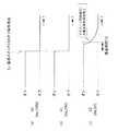
ここで、本発明の実施形態に係る変電所監視制御装置17の動作説明に先立って、変電所13内の各種機能部25,31,39への電源供給が不安定である場合に、変電所設備19の稼働状況に係る誤情報を検出し、この誤情報を通報してしまう作用機序について、図2を参照して説明する。図2(a)〜(c)は、変電所13内の各種機能部25,31,39にそれぞれ供給される、DC/DCコンバータ35が出力する3パターンの電圧経時波形を、電源スイッチ33のオン状態からオフ状態への切り替え操作時点t1を挟んで表す説明図である。
(Organization of problems according to the present invention)
Here, prior to explaining the operation of the substation monitoring and control device 17 according to the embodiment of the present invention, when the power supply to the various
図2(a)に示すように、電圧検出部37への電源供給端子29b1の電位に係る経時特性では、電源スイッチ33のオフ操作時点t1において、オン状態に対応する電源電位(V0;例えば100V以上などの電位レベルであって、本実施形態では110V)から、オフ状態に対応する電位(例えば10V以下など)へと遅延なく切り替わることがわかる。このとき、電圧検出部37は、電源スイッチ33がオフ操作された旨を検出すると、電源スイッチオフ検出信号を、信号線29cを介してA/D変換部39へと出力するように動作する。
As shown in FIG. 2A, in the time-dependent characteristics relating to the potential of the power supply terminal 29b1 to the
図2(b)に示すように、開閉状態検知センサ25への電源供給端子25a、および、A/D変換部39への電源供給端子29eの電位に係る経時特性では、図2(a)の例と同様に、電源スイッチ33のオフ操作時点t1において、オン状態に対応する第1電位(V1;例えば20V以上などの電位レベルであって、本実施形態では24V)から、オフ状態に対応する電位(例えば3V以下などの電位レベルであって、本実施形態では0V)へと遅延なく切り替わることがわかる。このとき、開閉状態検知センサ25は、電源供給端子25aの電位がオフ状態に対応する電位(0V)である旨の無電圧信号を、信号線29aを介してA/D変換部39へと出力するように動作する。
As shown in FIG. 2B, the time-dependent characteristics relating to the potentials of the
また、A/D変換部39は、電源スイッチ33がオフ操作された時点で入力されてきたアナログ信号を、ディジタル信号に変換して主制御部31へ出力するように動作する。これにより、主制御部31には、電源供給端子25aの電位レベルとして無電圧信号が伝達される。この無電圧信号の伝達が、後記するように、誤情報を生じる原因となる。
The A /
これに対し、図2(c)に示すように、マイコン(主制御部31)への電源供給端子29fの電位に係る経時特性では、電源スイッチ33のオフ操作時点t1において、オン状態に対応する第2電位(V2;本実施形態では3V以上で、定格電圧は5Vの電位レベル)をそのまま維持している。ここで、マイコン31の最低動作保証電圧(例えば3Vなどの、マイコンの仕様に従う電圧値)を考慮した場合、マイコン31への電源供給端子29fの電位が、オン状態に対応する第2電位(V2;3V以上)から、オフ状態に対応する最低動作保証電位(3V)未満へと切り替わるのに、所定の遅延時間Tdを要することがわかる。
On the other hand, as shown in FIG. 2C, the time-dependent characteristic relating to the potential of the
この遅延時間Tdの間は、マイコン31への電源供給端子29fの電位が、最低動作保証電圧以上に維持されている。このため、電源スイッチ33のオフ操作がなされた後も、マイコン31が正常動作を継続する。
During this delay time Td, the potential of the
これに対し、電源供給端子25a,29eの電位に係る経時特性では、図2(b)に示すように、電源スイッチ33のオフ操作時点t1から遅延なくオフ状態へと切り替わっている。このとき、開閉状態検知センサ25は、“低レベル”に対応する開閉状態を検知した状態となり、こうして検知された開閉状態検知センサ25の出力信号が、電源スイッチ33のオフ操作がなされた後であって、マイコン(主制御部31)が正常動作を継続している期間に供給される。
On the other hand, in the time-dependent characteristics relating to the potentials of the
ここで、遮断器23の開閉状態と、開閉状態検知センサ25の出力信号との対応関係の設定例について、表1を参照して説明する。遮断器23の開閉状態が“開放”である場合において、これに対応する開閉状態検知センサ25の出力信号は、表1に示すように、“低レベル”(電源スイッチ33のオン時)に設定されているものとする。また、遮断器23の開閉状態が“閉止”である場合において、これに対応する開閉状態検知センサ25の出力信号は、表1に示すように、“高レベル”(電源スイッチ33のオン時)に設定されているものとする。
遮断器23の開閉状態と、開閉状態検知センサ25の出力信号との対応関係が、前記のように設定されている場合に、電源スイッチ33がオフ操作されたとする。この場合、開閉状態検知センサ25は、表1に示すように、遮断器23の開閉状態が“開放”または“閉止”のいずれであるかとは無関係に、“低レベル”の無電圧信号を出力する。これは、開閉状態検知センサ25は、電源電位V1の供給がなければ、正常な動作を行うことができないことに基づく。そして、この“低レベル”の無電圧信号が、電源スイッチ33のオフ操作がなされた後であって、マイコン(主制御部31)の正常動作が継続している期間に供給される。
Assume that the
前記の場合において、マイコン(主制御部31)は、開閉状態検知センサ25が遮断器23の“開放”を検知したのか、または、実際とは異なる遮断器23の開閉状態に係る情報を誤って出力してしまったのか、を区別することができない(表1の2カ所の下線付与部分を対比して参照のこと)。その結果、変電所監視制御装置17への電源供給が不安定である場合において、変電所監視制御装置17は、変電所設備19の稼働状況に係る誤情報を検出し、この誤情報を通報してしまうおそれがあったのである。
In the above-described case, the microcomputer (main control unit 31) detects that the open / close
(本発明の実施形態に係る変電所監視制御装置17の動作)
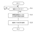
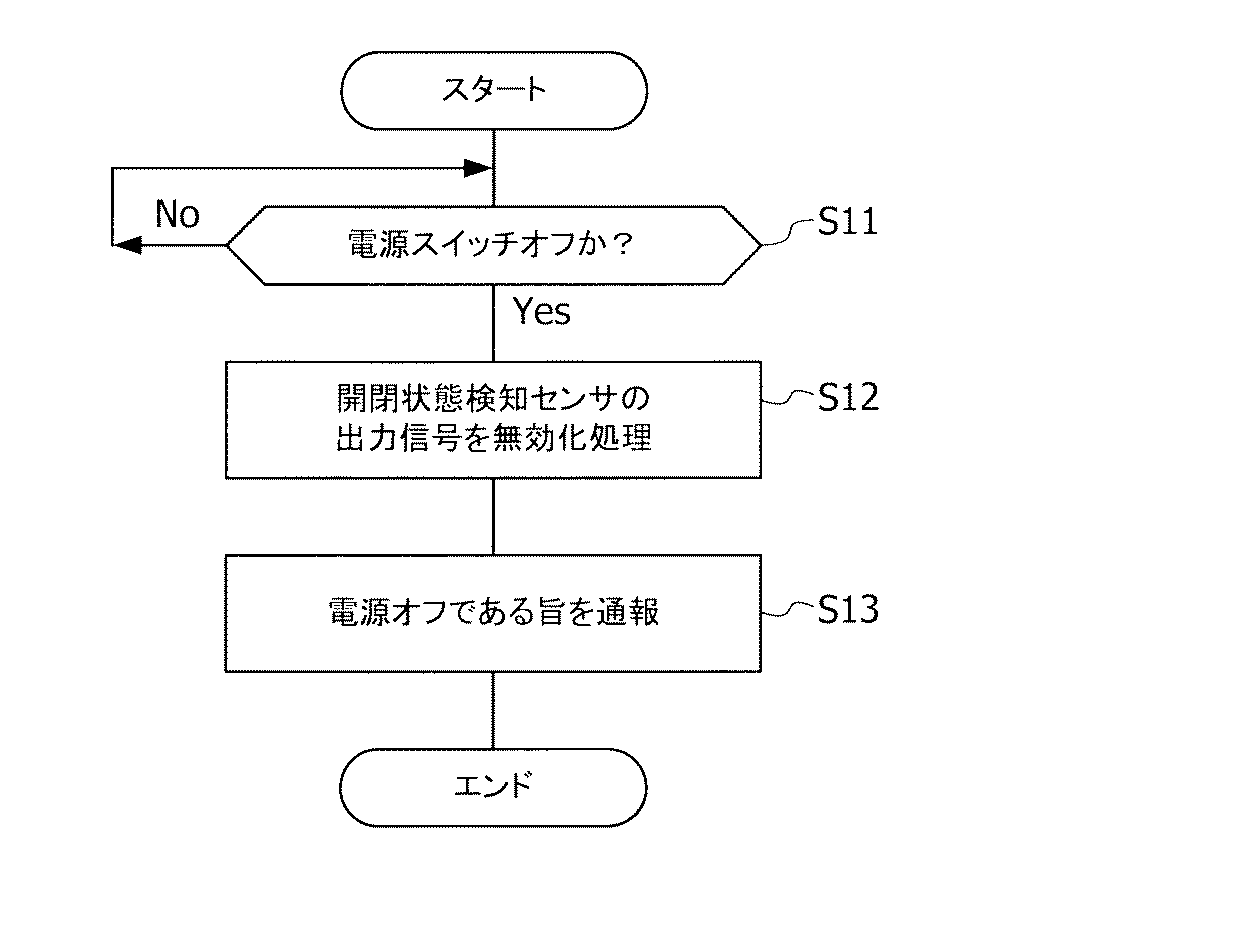
次に、本発明の実施形態に係る変電所監視制御装置17の動作について、図3を参照して説明する。図3は、本発明の実施形態に係る変電所監視制御装置17の動作説明に供するフローチャート図である。図3に示す処理の流れは、変電所監視制御装置17の稼働中において常時実行される。
(Operation of the substation monitoring and control device 17 according to the embodiment of the present invention)
Next, the operation of the substation monitoring and control device 17 according to the embodiment of the present invention will be described with reference to FIG. FIG. 3 is a flowchart for explaining the operation of the substation monitoring and control device 17 according to the embodiment of the present invention. The process flow shown in FIG. 3 is always executed while the substation monitoring control device 17 is in operation.
ステップS11において、電圧検出部35は、変電所監視制御装置17の稼働中に、電源スイッチ33がオフされたか否かを常時監視している。
In step S <b> 11, the
ステップS11の監視中に、電圧検出部35によって電源スイッチ33がオフされた旨が検出されると、主制御部31は、処理の流れを次のステップS12へと進ませる。
なお、ステップS11の監視処理は、電源スイッチ33がオン状態からオフ状態に切り替え操作されるまでの間、電位V0の電源供給を受けながら、継続して実行される。
If the
Note that the monitoring process in step S11 is continuously executed while receiving the power supply of the potential V0 until the
ステップS12において、無効化処理部43は、変電所情報検出部41が行う検出動作を無効化(第1の態様)する。これにより、無効化処理部43は、開閉状態検出センサ25の出力信号を無効化する処理を実行する。
In step S12, the invalidation processing unit 43 invalidates the detection operation performed by the substation information detection unit 41 (first mode). Thereby, the invalidation processing unit 43 executes a process of invalidating the output signal of the open / closed
なお、ステップS12の無効化処理は、電源スイッチ33のオフ操作がなされた後から、遅延時間Tdが過ぎる前までの、マイコン(主制御部31)が正常動作を継続している期間に実行される。ステップS12の無効化処理を実行後に、主制御部31は、処理の流れを次のステップS13へと進ませる。
The invalidation process in step S12 is executed during a period in which the microcomputer (main control unit 31) continues normal operation after the
ステップS13において、通報制御部45は、給電制御所13の変電所統括管理装置51宛に、変電所監視制御装置17は電源オフ状態にある旨を通知する。この通知は、通報制御部45が、変電所設備19の稼働状況に係る情報を、変電所統括管理装置51宛に通報する制御を実行することによって遂行される。
In step S13, the notification control unit 45 notifies the substation supervising
なお、ステップS13の通報制御処理は、電源スイッチ33のオフ操作がなされた後から、遅延時間Tdが過ぎる前までの、マイコン(主制御部31)が正常動作を継続している期間に実行される。ステップS13の通報制御処理を実行後に、主制御部31は、一連の処理の流れを終了させる。
The notification control process in step S13 is executed during a period in which the microcomputer (main control unit 31) continues normal operation after the
(本発明の実施形態に係る変電所監視制御装置17が奏する作用効果)
本発明の実施形態に係る変電所監視制御装置17では、無効化処理部43は、変電所13内の各種機能部25,31,39への電源供給が不安定である場合に、変電所情報検出部41および通報制御部45の動作を無効化するように動作する。したがって、本発明の実施形態に係る変電所監視制御装置17によれば、変電所監視制御装置17への電源供給が不安定である場合であっても、変電所設備19の稼働状況に係る誤情報の通報を未然に防ぐことができる。
(Operational effects produced by the substation monitoring and control device 17 according to the embodiment of the present invention)
In the substation monitoring and control device 17 according to the embodiment of the present invention, the invalidation processing unit 43 performs the substation information when the power supply to the various
本発明に係る主題“変電所設備19の稼働状況に係る誤情報の通報を未然に防ぐ”を実現するための実施態様として、大きく3つのアプローチがある。 There are roughly three approaches as embodiments for realizing the subject “preventing reporting of erroneous information relating to the operation status of the substation equipment 19” according to the present invention.
このうち、第1の態様“変電所情報検出部41が行う検出動作を無効化する”では、誤情報の発生源を元から絶つことによって、変電所設備19の稼働状況に係る誤情報の通報を未然に防ぐことができる。
Among these, in the first mode “invalidating the detection operation performed by the substation
また、第2の態様“通報制御部45が行う変電所設備19の稼働状況に係る情報の通報制御動作を無効化する”では、誤情報の流出源を水際で絶つことによって、変電所設備19の稼働状況に係る誤情報の通報を未然に防ぐことができる。 Further, in the second mode “invalidating the information control operation of information related to the operation status of the substation equipment 19 performed by the report control unit 45”, the substation equipment 19 It is possible to prevent reporting of misinformation related to the operating status.
そして、これら第1および第2の態様を組み合わせた第3の態様では、誤情報の発生源を元から絶つと共に誤情報の流出源を水際で絶つといった二重のフェールセーフ機構を構築することによって、変電所設備19の稼働状況に係る誤情報の通報を未然に防ぐことができる。 And in the 3rd mode which combined these 1st and 2nd modes, by constructing a double fail-safe mechanism that cuts off the source of erroneous information from the source and disconnects the source of erroneous information at the water's edge In addition, it is possible to prevent reporting of erroneous information related to the operation status of the substation equipment 19.
[その他の実施形態]
以上説明した実施形態は、本発明に係る具現化の例を示したものである。従って、この記載事項によって本発明の技術的範囲が限定的に解釈されることがあってはならない。本発明はその要旨またはその主要な特徴から逸脱することなく、様々な形態で実施することができるからである。
[Other Embodiments]
The embodiment described above shows an example of realization according to the present invention. Therefore, the technical scope of the present invention should not be limitedly interpreted by this description. This is because the present invention can be implemented in various forms without departing from the gist or main features thereof.
具体的には、例えば、本実施形態の説明において、変電所監視制御装置17から変電所設備19の稼働状況に係る情報の通報を受ける相手先として、給電制御所15の変電所統括管理装置51を例示して説明したが、本発明はこの例に限定されない。
Specifically, for example, in the description of the present embodiment, the substation supervising
変電所監視制御装置17から変電所設備19の稼働状況に係る情報の通報を受ける相手先としては、例えば、別の変電所の変電所監視制御装置であってもよいし、電力会社の管理下にある中央指令所の統括管理装置であってもよい。 For example, a substation monitoring and control device of another substation may be used as a counterpart to receive information on the operational status of the substation equipment 19 from the substation monitoring and control device 17, or under the control of the power company. May be a central management station of the central command station.
また、本実施形態の説明において、電気エネルギーを一時的に蓄えるコンデンサ(不図示)を含むDC/DCコンバータ(電力変換器)35が供給する電源の形態として、第1電位(V1;24V)の直流電源と、第2電位(V2;3V以上で、定格電圧は5V)の直流電源とを例示して説明したが、本発明はこの例に限定されない。DC/DCコンバータ(電力変換器)35が供給する電源の形態としては、電源の数、または、各電源の電位のいずれも、任意の値に設定すればよい。 In the description of the present embodiment, the first potential (V1; 24V) is used as a form of power supplied by a DC / DC converter (power converter) 35 including a capacitor (not shown) that temporarily stores electric energy. Although the DC power supply and the DC power supply of the second potential (V2; 3V or more and the rated voltage is 5V) have been described as examples, the present invention is not limited to this example. As a form of power supplied by the DC / DC converter (power converter) 35, the number of power supplies or the potential of each power supply may be set to an arbitrary value.
11 電力系統
13 変電所
15 給電制御所
16 通信線
17 変電所監視制御装置
19 変電所設備
23 遮断器(開閉機器)
25 開閉状態検知センサ
27 直流電源
31 主制御部
33 電源スイッチ
35 DC/DCコンバータ(電力変換器)
37 電圧検出部
39 A/D変換部
41 変電所情報検出部
43 無効化処理部
45 通報制御部
51 変電所統括管理装置(外部装置)
DESCRIPTION OF SYMBOLS 11 Electric power system 13 Substation 15 Power
25 Open / Closed
37 Voltage Detection Unit 39 A /
Claims (2)
前記変電所設備の稼働状況に係る変電所情報を検出する変電所情報検出部と、
前記変電所情報検出部で検出された前記変電所情報を外部装置へ通報する制御を行う通報制御部と、
前記変電所内の各種機能部への電源供給が不安定である場合に、前記変電所情報検出部および前記通報制御部の動作を無効化する無効化処理部と、
を備えることを特徴とする変電所監視制御装置。 In a substation monitoring and control device that monitors the operational status of substation equipment, including the switching status of switchgear in the substation,
A substation information detecting unit for detecting substation information related to the operating status of the substation equipment;
A notification control unit that performs control to report the substation information detected by the substation information detection unit to an external device;
When power supply to various functional units in the substation is unstable, an invalidation processing unit for invalidating the operation of the substation information detection unit and the notification control unit ,
A substation monitoring and control device comprising:
前記変電所内の各種機能部への電源供給は、電気エネルギーを一時的に蓄えるコンデンサを含む電力変換器を介して行われる、
ことを特徴とする変電所監視制御装置。 The substation monitoring and control device according to claim 1,
Power supply to various functional units in the substation is performed via a power converter including a capacitor that temporarily stores electrical energy.
Substation monitoring and control device characterized by that.
Priority Applications (1)
| Application Number | Priority Date | Filing Date | Title |
|---|---|---|---|
| JP2011155322A JP5628107B2 (en) | 2011-07-14 | 2011-07-14 | Substation monitoring and control equipment |
Applications Claiming Priority (1)
| Application Number | Priority Date | Filing Date | Title |
|---|---|---|---|
| JP2011155322A JP5628107B2 (en) | 2011-07-14 | 2011-07-14 | Substation monitoring and control equipment |
Publications (2)
| Publication Number | Publication Date |
|---|---|
| JP2013021881A JP2013021881A (en) | 2013-01-31 |
| JP5628107B2 true JP5628107B2 (en) | 2014-11-19 |
Family
ID=47692763
Family Applications (1)
| Application Number | Title | Priority Date | Filing Date |
|---|---|---|---|
| JP2011155322A Active JP5628107B2 (en) | 2011-07-14 | 2011-07-14 | Substation monitoring and control equipment |
Country Status (1)
| Country | Link |
|---|---|
| JP (1) | JP5628107B2 (en) |
Families Citing this family (1)
| Publication number | Priority date | Publication date | Assignee | Title |
|---|---|---|---|---|
| KR101505176B1 (en) * | 2014-10-15 | 2015-03-24 | 한국전력공사 | Apparatus and method for detecting failure of bus |
Family Cites Families (6)
| Publication number | Priority date | Publication date | Assignee | Title |
|---|---|---|---|---|
| JPS6258743A (en) * | 1985-09-06 | 1987-03-14 | Hitachi Ltd | Abnormality detecting device for remote supervisory data |
| JP3034717B2 (en) * | 1993-03-09 | 2000-04-17 | 株式会社日立製作所 | Power monitoring and control system |
| JP3352411B2 (en) * | 1998-03-05 | 2002-12-03 | 株式会社東芝 | Control system, power system protection control system, and storage medium storing program |
| JP2005056156A (en) * | 2003-08-05 | 2005-03-03 | Tm T & D Kk | Monitoring and controlling system |
| JP2006033441A (en) * | 2004-07-16 | 2006-02-02 | Meidensha Corp | Remote monitoring system |
| JP5259069B2 (en) * | 2006-10-02 | 2013-08-07 | 株式会社東芝 | Circuit breaker switching control system |
-
2011
- 2011-07-14 JP JP2011155322A patent/JP5628107B2/en active Active
Also Published As
| Publication number | Publication date |
|---|---|
| JP2013021881A (en) | 2013-01-31 |
Similar Documents
| Publication | Publication Date | Title |
|---|---|---|
| CN101299536A (en) | Power system safety stabilization emergency control policy automatically matching method | |
| JP2014193107A (en) | Highly reliable static transfer switch circuit for uninterruptible power supply system | |
| CN104991628B (en) | Intelligent power monitoring system and monitoring method for data center | |
| CN104297676A (en) | Method, device and system for monitoring circuit breaker of wind generating set | |
| JP5628107B2 (en) | Substation monitoring and control equipment | |
| KR101283873B1 (en) | Trouble-free automatic photovoltaic power generation management system | |
| CN106300462A (en) | Electricity circuit under battery | |
| CN202997683U (en) | A double power supply automatic switching device | |
| CN106229968B (en) | A kind of interlock and its control method | |
| CN112751316B (en) | Configuration method and device for power failure of bus voltage transformer | |
| CN101826719A (en) | Trip-proof lockout microcomputer protection system | |
| CN201717611U (en) | Anti-tripping latching protection system for microcomputers | |
| CN204835696U (en) | Switching of power device based on DCS | |
| CN209982170U (en) | UPS (uninterrupted power supply) fault switching device | |
| CN207753501U (en) | The air compressor machine of anti-low voltage crossing controls power supply | |
| CN112366811A (en) | Power supply switching device and method for automatically detecting running state of generator | |
| JP6612990B2 (en) | Power converter | |
| WO2019159513A1 (en) | Power storage control device, power storage control method, and computer program | |
| CN106505728B (en) | Power supply control loop of wind power doubly-fed converter in grid connection | |
| CN111262222A (en) | Intelligent reclosing control system | |
| CN205791787U (en) | A kind of automation control system electric supply installation | |
| CN218243021U (en) | Energy storage system capable of being remotely controlled | |
| CN104362578B (en) | Can reclosing RCCB | |
| CN111049095B (en) | Cross-region integrated relay protection system | |
| CN105471095A (en) | Low-voltage AC looped network loop power supply monitoring method |
Legal Events
| Date | Code | Title | Description |
|---|---|---|---|
| A621 | Written request for application examination |
Free format text: JAPANESE INTERMEDIATE CODE: A621 Effective date: 20130723 |
|
| A977 | Report on retrieval |
Free format text: JAPANESE INTERMEDIATE CODE: A971007 Effective date: 20140514 |
|
| A131 | Notification of reasons for refusal |
Free format text: JAPANESE INTERMEDIATE CODE: A131 Effective date: 20140520 |
|
| A521 | Written amendment |
Free format text: JAPANESE INTERMEDIATE CODE: A523 Effective date: 20140722 |
|
| TRDD | Decision of grant or rejection written | ||
| A01 | Written decision to grant a patent or to grant a registration (utility model) |
Free format text: JAPANESE INTERMEDIATE CODE: A01 Effective date: 20140909 |
|
| A61 | First payment of annual fees (during grant procedure) |
Free format text: JAPANESE INTERMEDIATE CODE: A61 Effective date: 20141001 |
|
| R150 | Certificate of patent or registration of utility model |
Ref document number: 5628107 Country of ref document: JP Free format text: JAPANESE INTERMEDIATE CODE: R150 |