JP5618710B2 - Bus controller integrated with power supply device for process control system - Google Patents
Bus controller integrated with power supply device for process control system Download PDFInfo
- Publication number
- JP5618710B2 JP5618710B2 JP2010195500A JP2010195500A JP5618710B2 JP 5618710 B2 JP5618710 B2 JP 5618710B2 JP 2010195500 A JP2010195500 A JP 2010195500A JP 2010195500 A JP2010195500 A JP 2010195500A JP 5618710 B2 JP5618710 B2 JP 5618710B2
- Authority
- JP
- Japan
- Prior art keywords
- bus
- power
- controller
- terminal
- output
- Prior art date
- Legal status (The legal status is an assumption and is not a legal conclusion. Google has not performed a legal analysis and makes no representation as to the accuracy of the status listed.)
- Active
Links
- 238000004886 process control Methods 0.000 title claims description 43
- 238000004891 communication Methods 0.000 claims description 135
- 238000000034 method Methods 0.000 claims description 58
- 230000008569 process Effects 0.000 claims description 51
- 230000007547 defect Effects 0.000 claims description 9
- 230000001419 dependent effect Effects 0.000 claims description 5
- 238000009413 insulation Methods 0.000 claims description 4
- 230000008878 coupling Effects 0.000 claims description 2
- 238000010168 coupling process Methods 0.000 claims description 2
- 238000005859 coupling reaction Methods 0.000 claims description 2
- 229920000856 Amylose Polymers 0.000 claims 3
- 238000010292 electrical insulation Methods 0.000 claims 1
- 230000006870 function Effects 0.000 description 50
- 238000013461 design Methods 0.000 description 22
- 230000009977 dual effect Effects 0.000 description 21
- 238000010586 diagram Methods 0.000 description 14
- 238000012544 monitoring process Methods 0.000 description 11
- 238000001514 detection method Methods 0.000 description 8
- 230000001012 protector Effects 0.000 description 8
- 238000005259 measurement Methods 0.000 description 7
- 241000196324 Embryophyta Species 0.000 description 6
- 238000013480 data collection Methods 0.000 description 6
- 238000013500 data storage Methods 0.000 description 6
- 238000007726 management method Methods 0.000 description 6
- 238000002955 isolation Methods 0.000 description 5
- 238000004519 manufacturing process Methods 0.000 description 5
- 238000012546 transfer Methods 0.000 description 5
- 239000002131 composite material Substances 0.000 description 4
- 230000003750 conditioning effect Effects 0.000 description 4
- 230000001276 controlling effect Effects 0.000 description 4
- 230000008859 change Effects 0.000 description 3
- 238000003745 diagnosis Methods 0.000 description 3
- 238000013154 diagnostic monitoring Methods 0.000 description 3
- 230000001105 regulatory effect Effects 0.000 description 3
- 230000004913 activation Effects 0.000 description 2
- 230000005540 biological transmission Effects 0.000 description 2
- 238000011217 control strategy Methods 0.000 description 2
- 231100001010 corrosive Toxicity 0.000 description 2
- 238000005516 engineering process Methods 0.000 description 2
- 230000010365 information processing Effects 0.000 description 2
- 238000012986 modification Methods 0.000 description 2
- 230000004048 modification Effects 0.000 description 2
- 238000012545 processing Methods 0.000 description 2
- 230000005855 radiation Effects 0.000 description 2
- 230000008054 signal transmission Effects 0.000 description 2
- 229910000679 solder Inorganic materials 0.000 description 2
- 238000004804 winding Methods 0.000 description 2
- 235000002566 Capsicum Nutrition 0.000 description 1
- 239000006002 Pepper Substances 0.000 description 1
- 235000016761 Piper aduncum Nutrition 0.000 description 1
- 235000017804 Piper guineense Nutrition 0.000 description 1
- 244000203593 Piper nigrum Species 0.000 description 1
- 235000008184 Piper nigrum Nutrition 0.000 description 1
- 241000282485 Vulpes vulpes Species 0.000 description 1
- 230000009471 action Effects 0.000 description 1
- 230000008901 benefit Effects 0.000 description 1
- 239000003990 capacitor Substances 0.000 description 1
- 239000003518 caustics Substances 0.000 description 1
- 238000005553 drilling Methods 0.000 description 1
- 230000000694 effects Effects 0.000 description 1
- 230000007613 environmental effect Effects 0.000 description 1
- 238000001914 filtration Methods 0.000 description 1
- 230000017525 heat dissipation Effects 0.000 description 1
- 230000036039 immunity Effects 0.000 description 1
- 238000012905 input function Methods 0.000 description 1
- 230000002452 interceptive effect Effects 0.000 description 1
- 239000004922 lacquer Substances 0.000 description 1
- 239000007788 liquid Substances 0.000 description 1
- 238000012423 maintenance Methods 0.000 description 1
- 230000007257 malfunction Effects 0.000 description 1
- 239000000463 material Substances 0.000 description 1
- 230000007246 mechanism Effects 0.000 description 1
- 230000003287 optical effect Effects 0.000 description 1
- 230000000704 physical effect Effects 0.000 description 1
- 230000003863 physical function Effects 0.000 description 1
- 238000007670 refining Methods 0.000 description 1
- 230000004044 response Effects 0.000 description 1
- 230000002441 reversible effect Effects 0.000 description 1
- 238000003756 stirring Methods 0.000 description 1
- 239000000126 substance Substances 0.000 description 1
- 239000000758 substrate Substances 0.000 description 1
- 230000008646 thermal stress Effects 0.000 description 1
- 230000001052 transient effect Effects 0.000 description 1
Images


Classifications
-
- H—ELECTRICITY
- H04—ELECTRIC COMMUNICATION TECHNIQUE
- H04L—TRANSMISSION OF DIGITAL INFORMATION, e.g. TELEGRAPHIC COMMUNICATION
- H04L25/00—Baseband systems
- H04L25/02—Details ; arrangements for supplying electrical power along data transmission lines
-
- H—ELECTRICITY
- H04—ELECTRIC COMMUNICATION TECHNIQUE
- H04B—TRANSMISSION
- H04B3/00—Line transmission systems
- H04B3/54—Systems for transmission via power distribution lines
- H04B3/548—Systems for transmission via power distribution lines the power on the line being DC
-
- G—PHYSICS
- G05—CONTROLLING; REGULATING
- G05B—CONTROL OR REGULATING SYSTEMS IN GENERAL; FUNCTIONAL ELEMENTS OF SUCH SYSTEMS; MONITORING OR TESTING ARRANGEMENTS FOR SUCH SYSTEMS OR ELEMENTS
- G05B19/00—Programme-control systems
- G05B19/02—Programme-control systems electric
- G05B19/418—Total factory control, i.e. centrally controlling a plurality of machines, e.g. direct or distributed numerical control [DNC], flexible manufacturing systems [FMS], integrated manufacturing systems [IMS] or computer integrated manufacturing [CIM]
- G05B19/4185—Total factory control, i.e. centrally controlling a plurality of machines, e.g. direct or distributed numerical control [DNC], flexible manufacturing systems [FMS], integrated manufacturing systems [IMS] or computer integrated manufacturing [CIM] characterised by the network communication
-
- H—ELECTRICITY
- H04—ELECTRIC COMMUNICATION TECHNIQUE
- H04L—TRANSMISSION OF DIGITAL INFORMATION, e.g. TELEGRAPHIC COMMUNICATION
- H04L12/00—Data switching networks
- H04L12/28—Data switching networks characterised by path configuration, e.g. LAN [Local Area Networks] or WAN [Wide Area Networks]
- H04L12/40—Bus networks
- H04L12/40006—Architecture of a communication node
- H04L12/40013—Details regarding a bus controller
-
- H—ELECTRICITY
- H04—ELECTRIC COMMUNICATION TECHNIQUE
- H04L—TRANSMISSION OF DIGITAL INFORMATION, e.g. TELEGRAPHIC COMMUNICATION
- H04L25/00—Baseband systems
- H04L25/02—Details ; arrangements for supplying electrical power along data transmission lines
- H04L25/0264—Arrangements for coupling to transmission lines
- H04L25/0278—Arrangements for impedance matching
-
- H—ELECTRICITY
- H04—ELECTRIC COMMUNICATION TECHNIQUE
- H04L—TRANSMISSION OF DIGITAL INFORMATION, e.g. TELEGRAPHIC COMMUNICATION
- H04L25/00—Baseband systems
- H04L25/02—Details ; arrangements for supplying electrical power along data transmission lines
- H04L25/0264—Arrangements for coupling to transmission lines
- H04L25/0298—Arrangement for terminating transmission lines
-
- H—ELECTRICITY
- H04—ELECTRIC COMMUNICATION TECHNIQUE
- H04B—TRANSMISSION
- H04B2203/00—Indexing scheme relating to line transmission systems
- H04B2203/54—Aspects of powerline communications not already covered by H04B3/54 and its subgroups
- H04B2203/5429—Applications for powerline communications
- H04B2203/5458—Monitor sensor; Alarm systems
-
- H—ELECTRICITY
- H04—ELECTRIC COMMUNICATION TECHNIQUE
- H04L—TRANSMISSION OF DIGITAL INFORMATION, e.g. TELEGRAPHIC COMMUNICATION
- H04L25/00—Baseband systems
- H04L25/02—Details ; arrangements for supplying electrical power along data transmission lines
- H04L25/0264—Arrangements for coupling to transmission lines
- H04L25/0266—Arrangements for providing Galvanic isolation, e.g. by means of magnetic or capacitive coupling
-
- Y—GENERAL TAGGING OF NEW TECHNOLOGICAL DEVELOPMENTS; GENERAL TAGGING OF CROSS-SECTIONAL TECHNOLOGIES SPANNING OVER SEVERAL SECTIONS OF THE IPC; TECHNICAL SUBJECTS COVERED BY FORMER USPC CROSS-REFERENCE ART COLLECTIONS [XRACs] AND DIGESTS
- Y02—TECHNOLOGIES OR APPLICATIONS FOR MITIGATION OR ADAPTATION AGAINST CLIMATE CHANGE
- Y02P—CLIMATE CHANGE MITIGATION TECHNOLOGIES IN THE PRODUCTION OR PROCESSING OF GOODS
- Y02P90/00—Enabling technologies with a potential contribution to greenhouse gas [GHG] emissions mitigation
- Y02P90/02—Total factory control, e.g. smart factories, flexible manufacturing systems [FMS] or integrated manufacturing systems [IMS]
Landscapes
- Engineering & Computer Science (AREA)
- Computer Networks & Wireless Communication (AREA)
- Signal Processing (AREA)
- Power Engineering (AREA)
- Quality & Reliability (AREA)
- Manufacturing & Machinery (AREA)
- General Engineering & Computer Science (AREA)
- Physics & Mathematics (AREA)
- General Physics & Mathematics (AREA)
- Automation & Control Theory (AREA)
- Programmable Controllers (AREA)
- Dc Digital Transmission (AREA)
- Small-Scale Networks (AREA)
Description
本発明は、プロセスプラントや他のプロセスにおいて、プロセス制御処理の遂行に用いるバス依拠プロセス通信システムに概ね関し、より具体的にはプロセス制御通信システムに用いるバス依拠電源一体化バスコントローラに関する。 The present invention generally relates to a bus-dependent process communication system used to perform process control processing in a process plant and other processes, and more specifically to a bus-dependent power supply integrated bus controller used for a process control communication system.
プロセス制御システムは、製品を製造したりプロセスを制御したりする工場および/またはプロセスプラント内で幅広く用いられ(例えば、化学的製造や発電所制御や石油精製等)、幾つかの種類の製品を生産する。プロセス制御システムは、天然資源、例えば石油やガス等の産出や掘削処理プロセス等にも用いられている。どのような製造プロセスも殆どが、1以上のプロセス制御システムの適用を通じて資源産出プロセス等を自動化することができる。 Process control systems are widely used in factories and / or process plants that manufacture products or control processes (eg, chemical manufacturing, power plant control, oil refining, etc.), Produce. Process control systems are also used in the production of natural resources, such as oil and gas, and drilling processes. Most of any manufacturing process can automate resource production processes, etc. through the application of one or more process control systems.
プロセス制御システムを実装する仕方は、何年にも渡って進化してきた。旧世代のプロセス制御システムは通常、専用の中央統合ハードウェアを用いて実装されていた。しかしながら、最新のプロセス制御システムは一般に、作業端末や知的コントローラや高性能のフィールドデバイス等で、その一部または全てがプロセス制御全体のストラテジあるいはスキームの一部を遂行することのできる高度分散ネットワークを用いて実装される。特に、大半の最新のプロセス制御システムは、1以上のデジタルのあるいはデジタルとアナログが複合されたデータバスを介して相互にかつ/または1以上のプロセスコントローラに通信可能に結合した高性能のフィールドデバイスや他のプロセス制御構成要素を含んでいる。無論、これらの最新の制御システムの多くは、例えば4〜20ミリアンペア(MA)デバイスや0〜10ボルト直流(VDC)デバイス等もまた含むことがあり、それらは共有デジタルバス等を使用するのとは対照的に一般にコントローラへ直接結合される。 The way in which process control systems are implemented has evolved over the years. Older generation process control systems were typically implemented using dedicated central integrated hardware. However, the latest process control systems are generally highly distributed networks, such as work terminals, intelligent controllers, and high performance field devices, some or all of which can execute part of the overall process control strategy or scheme. Implemented using. In particular, most modern process control systems include high performance field devices that are communicatively coupled to each other and / or to one or more process controllers via one or more digital or combined digital and analog data buses. And other process control components. Of course, many of these modern control systems may also include, for example, 4-20 milliamp (MA) devices, 0-10 volt direct current (VDC) devices, etc., which use shared digital buses, etc. Is generally coupled directly to the controller.
より具体的には、分散させあるいは規模拡大が可能なプロセス制御システム等の最新のプロセス制御システムは一般に、アナログやデジタルあるいはアナログ/デジタル複合バスを介し、相互にあるいは少なくとも1個のホストのまたはオペレータの作業端末や1以上のフィールドデバイスに通信可能に結合された1以上のプロセスコントローラを含んでいる。フィールドデバイスは、例えばバルブやバルブポジショナやスイッチや送信器(例えば、温度、圧力、流量センサ)とされることがあるが、バルブの開閉やプロセスパラメータの計測等のプロセス内の機能を遂行する。プロセスコントローラは、フィールドデバイスが作成するプロセス計測値および/またはフィールドデバイスに属する他の情報等を示す信号を受け取り、この情報を用いて1以上の制御ルーチンを実行し、バス上をフィールドデバイスへ送信されてプロセスの操作を制御する制御信号を生成する。フィールドデバイスやコントローラからの情報は通常、オペレータ作業端末が実行する1以上のアプリケーションに利用可能とされており、プロセスの現況を視認したりプロセスの操作を修正したりする等のプロセスに対するあらゆる所望の機能をオペレータが遂行できるようにしてある。 More specifically, modern process control systems, such as process control systems that can be distributed or scaled, are typically connected to each other or to at least one host or operator via an analog, digital or analog / digital composite bus. And one or more process controllers communicatively coupled to one or more work terminals and one or more field devices. The field device may be, for example, a valve, a valve positioner, a switch, or a transmitter (for example, temperature, pressure, flow rate sensor), and performs a function in the process such as opening / closing of a valve or measurement of a process parameter. The process controller receives a signal indicating a process measurement value created by the field device and / or other information belonging to the field device, etc., and executes one or more control routines using this information, and transmits the signal on the bus to the field device. A control signal for controlling the operation of the process. Information from field devices and controllers is usually made available to one or more applications executed by the operator work terminal, and any desired process for the process, such as viewing the current state of the process or modifying the operation of the process. The function can be performed by the operator.
エマーソン・プロセス・マネージメント(Emerson_Process_Management)が販売するDeltaV(登録商標)システム等の一部のプロセス制御システムは、プロセスコントローラ内や異なるフィールドデバイスあるいは入/出力(I/O)コントローラ内に配置されて制御操作を遂行するモジュールと呼ぶ機能ブロックあるいは機能ブロック群を用いている。これらの場合、プロセスコントローラや他のデバイスは、1以上の機能ブロックやモジュールを含みこれを実行することができ、そのそれぞれが(同一のデバイス内かあるいは異なるデバイス内のいずれかで)他の機能ブロックから入力を受け取り、かつ/またはそこへ出力を供給し、プロセスパラメータを計測しあるいは検出し、デバイスを制御し、比例−微分−積分(PID)制御ルーチンを実行する等の制御操作を遂行する等の何らかのプロセス制御操作を遂行する。プロセス制御システム内の異なる機能ブロックおよびモジュールは一般に、(例えば、バス上で)互いに通信して1以上のプロセス制御ループを形成するよう構成される。 Some process control systems, such as the DeltaV® system sold by Emerson Process Management (Emerson_Process_Management), are located in the process controller or in different field devices or input / output (I / O) controllers for control A functional block or a functional block group called a module for performing an operation is used. In these cases, the process controller or other device can contain and execute one or more functional blocks or modules, each of which can perform other functions (either in the same device or in different devices). Performs control operations such as receiving inputs from blocks and / or providing outputs thereto, measuring or detecting process parameters, controlling devices, and executing proportional-derivative-integral (PID) control routines Perform some process control operations such as Different functional blocks and modules within a process control system are generally configured to communicate with each other (eg, on a bus) to form one or more process control loops.
多くの場合、プロセスコントローラは、流量制御ループや温度制御ループや圧力制御ループ等のプロセス用に規定されあるいはその中に含まれる多数の異なるループごとに、異なるアルゴリズムやサブルーチンや制御ループ(これらは全て制御ルーチンである)を実行するようプログラムされている。概して、この種の制御ループはそれぞれ、アナログ入力(AI)機能ブロック等の1以上の入力ブロックと、比例−積分−微分(PID)やファジー論理制御機能ブロック等の制御ブロックと、アナログ出力(AO)機能ブロック等の出力ブロックとを含んでいる。制御ルーチンとこの種ルーチンを実行する機能ブロックは、例えばPID制御やファジー論理制御、Smith予測器あるいはモデル予測制御(MPC)等のモデル依拠制御技法を含む多数の制御技法に従って構成されてきた。 In many cases, the process controller will have a different algorithm, subroutine, or control loop for each of the many different loops defined or included in the process, such as flow control loops, temperature control loops, pressure control loops, etc. Control routine). Generally, each of these types of control loops includes one or more input blocks such as analog input (AI) function blocks, control blocks such as proportional-integral-derivative (PID) and fuzzy logic control function blocks, and analog output (AO). ) Output blocks such as functional blocks. Control routines and functional blocks that execute such routines have been organized according to a number of control techniques including, for example, model-based control techniques such as PID control, fuzzy logic control, Smith predictor or model predictive control (MPC).
この数の増えたコントローラ機能が、プロセス制御システム内にあってコントローラ機能をサポートする異なるデバイス間で生ずるに違いないデータ転送レベルの増大に繋がる。従って、最新のプロセス制御システム設計の一つの特に重要な側面には、フィールドデバイスを相互に、かつプロセス制御システムあるいはプロセスプラント内のプロセスコントローラや他のシステムあるいはデバイスと通信可能に結合させる仕方が含まれる。一般に、フィールドデバイスがプロセス制御システム内で機能できるようにする様々な通信チャネル、リンクおよびパスは、集合的に入/出力(I/O)通信ネットワークと呼ばれる。 This increased number of controller functions leads to an increased level of data transfer that must occur between different devices in the process control system that support the controller function. Thus, one particularly important aspect of modern process control system design includes the way in which field devices are communicatively coupled to each other and to process controllers and other systems or devices in the process control system or process plant. It is. In general, the various communication channels, links and paths that enable a field device to function within a process control system are collectively referred to as an input / output (I / O) communication network.
I/O通信ネットワークの実装に用いられる通信ネットワーク空間配置や物理的接続路やパスは、特にI/O通信ネットワークがプロセス制御システムに関連する環境的要因や条件にさらされるときに、フィールドデバイス通信の耐性や完全性に対しかなり強い影響を及ぼすことがある。例えば、多くの工業的な制御アプリケーションは、往々にしてフィールドデバイスやそれらの関連するI/O通信ネットワークを苛酷な物理的な環境(例えば、高温や低温あるいは激しく変化する周囲温度や振動や腐食性ガスまたは液体等)や、厄介な電気的環境(例えば、ノイズの多い環境や劣悪な電源品質や一過性電圧)等にさらすものである。その結果、多数の異種I/O通信ネットワークおよび通信プロトコルが、これらネットワーク上での通信の提供に用いるべく開発されてきた。 The communication network space layout, physical connection paths and paths used to implement the I / O communication network are field device communication, especially when the I / O communication network is exposed to environmental factors and conditions associated with the process control system. Can have a rather strong effect on the tolerance and integrity of For example, many industrial control applications often use field devices and their associated I / O communication networks in harsh physical environments (eg, high and low temperatures or rapidly changing ambient temperatures, vibrations and corrosives). Gas, liquid, etc.), troublesome electrical environment (for example, noisy environment, poor power quality and transient voltage), etc. As a result, a number of heterogeneous I / O communication networks and communication protocols have been developed for use in providing communication over these networks.
より具体的には、分散されたプロセス制御システム内での制御ルーチンの実行をサポートすべく、一般的な工業用あるいはプロセス用プラントは統合制御室を有し、該統合制御室が1以上の分散プロセスコントローラやプロセスI/Oサブシステムと通信可能に接続され、該分散プロセスコントローラやプロセスI/Oサブシステムをプロセス変数の計測やプラント内での物理的動作の遂行(例えば、バルブの開弁や閉弁)等のプラント内での制御動作を遂行する1以上のフィールドデバイスに接続されている。これまで、アナログのフィールドデバイスは信号伝送と電力の供給用に2線式あるいは4線式の電流ループによりコントローラへ接続されてきた。制御室へ信号を伝送するアナログのフィールドデバイス(例えば、センサや伝送器)は、電流ループを流れる電流を変調し、電流が被検出プロセス変数に比例するようにしている。他方、制御室の制御下で1つの動作を遂行するアナログのフィールドデバイスは、ループを流れる電流の大きさにより制御される。 More specifically, to support the execution of control routines within a distributed process control system, a typical industrial or process plant has an integrated control room that has one or more distributed control rooms. The distributed process controller and the process I / O subsystem are communicably connected to a process controller and a process I / O subsystem. It is connected to one or more field devices that perform control operations in the plant, such as valve closing. Until now, analog field devices have been connected to the controller via a two-wire or four-wire current loop for signal transmission and power supply. Analog field devices (eg, sensors and transmitters) that transmit signals to the control room modulate the current flowing through the current loop so that the current is proportional to the detected process variable. On the other hand, an analog field device that performs an operation under the control of a control room is controlled by the magnitude of the current flowing through the loop.
しかしながら、さらに最近では、アナログ信号の伝送に用いる電流ループ上にデジタルデータを重畳するプロセス制御通信システムが開発されてきている。例えば、ハイウェイ・アドレッサブル・リモート・トランスデューサ(HART(登録商標):Highway_Addressable_Remote_Transducer)プロトコルはアナログ信号の送受信にループ電流の大きさを用いるものであるが、電流ループ信号上にデジタルの搬送信号を重畳し、高性能のフィールド機器との双方向フィールド通信もまた可能にする。さらにまた、I/O通信ネットワークに関連するバス上で全てのデジタル通信を提供する他のプロトコルが開発されてきている。例えば、FOUNDATION(登録商標)フィールドバスプロトコルは、一般にフィールドバス(Fieldbus)プロトコルと呼ばれており、全デジタルI/O通信ネットワークに関連するバス上に全てのデジタル通信を提供する。フィールドバスプロトコルは実際、ネットワークに結合したフィールドデバイスに給電する一方で、最大毎秒31.25キロビットのレートでのデータ転送をサポートするH1プロトコルと、バスを介してフィールドデバイスへ電力を供給することなく最大毎秒2.5メガビットのレートでのデータ転送をサポートするH2プロトコルを含む2つのサブプロトコルを含んでいる。これらの種類の通信プロトコルを用いることで、一般に現に全てデジタルの、高性能のフィールドデバイスが、多くの保守モードと、旧来の制御システムが提供していない拡張機能とをサポートしている。しかしながら、これらのデジタル依拠通信プロトコルは通常、バス上での適切な通信を保証し、I/O通信ネットワーク等に取り付けられていないプロセスコントローラやユーザ・インタフェース・デバイス等の外部デバイスとのインタフェースをとるべく、時としてリンク・コントローラ・デバイスと呼ばれるバス・コントローラ・デバイスもまた必要とする。 More recently, however, process control communication systems have been developed that superimpose digital data on a current loop used for analog signal transmission. For example, the Highway Addressable Remote Transducer (HART (registered trademark): Highway_Addressable_Remote_Transducer) protocol uses the magnitude of the loop current to send and receive analog signals, but superimposes a digital carrier signal on the current loop signal, It also enables bi-directional field communication with high performance field devices. Furthermore, other protocols have been developed that provide all digital communication on the bus associated with the I / O communication network. For example, the FOUNDATION (R) Fieldbus protocol is commonly referred to as the Fieldbus protocol and provides all digital communication on the bus associated with an all-digital I / O communication network. The fieldbus protocol actually powers field devices coupled to the network, while supporting the H1 protocol that supports data transfer at a rate of up to 31.25 kilobits per second, and without powering the field devices over the bus It includes two sub-protocols including the H2 protocol that supports data transfer at a rate of up to 2.5 megabits per second. By using these types of communication protocols, generally all digital, high performance field devices support many maintenance modes and extended functions not provided by traditional control systems. However, these digitally based communication protocols typically ensure proper communication over the bus and interface with external devices such as process controllers and user interface devices that are not attached to an I / O communication network or the like. Thus, a bus controller device, sometimes called a link controller device, is also required.
上述のように、I/O通信ネットワークの一部およびこれらネットワークに関連するプロトコルが、網路バス上でのデジタルおよび/またはアナログ信号の通信に加え、ネットワークに接続されたフィールドデバイスへ電力を供給するよう開発されてきた。網路バス上に電力(本願明細書ではバス電力と呼ぶ)を供給することで、I/O通信ネットワーク自体はこのI/O通信ネットワークに接続されたフィールドデバイスや他のデバイスに給電できるようになり、それによってI/O通信ネットワークに接続された各フィールドデバイスやコントローラ等へ個別電源を提供する必要性が取り除かれる。この機能は、戸外や苛酷な環境あるいは遠隔地や簡単にアクセスできない場所に実装されるプロセス制御システムに非常に有用である。しかしながら、バス電力機能は封鎖プラントや他のより旧来の場所においても極めて有用である。何故ならそれはプロセス制御システム内の各フィールドデバイスに対し個別の電力信号を供給するのに必要な配線や結線を減らすからである。 As described above, portions of I / O communication networks and protocols associated with these networks provide power to field devices connected to the network in addition to communicating digital and / or analog signals over the network bus Has been developed to do. By supplying power (referred to as bus power in this specification) on the network bus, the I / O communication network itself can supply power to field devices and other devices connected to the I / O communication network. This eliminates the need to provide a separate power supply to each field device, controller, etc. connected to the I / O communication network. This feature is very useful for process control systems that are implemented outdoors, in harsh environments, or in remote locations or places that are not easily accessible. However, the bus power function is also extremely useful in blockade plants and other older locations. This is because it reduces the wiring and connections required to supply individual power signals to each field device in the process control system.
一般に、バス電力を供給するI/O通信ネットワークは、バスに接続して適当な電力信号を使用対象バスへ乗せ、このバスに接続された他のデバイスへ給電するのに用いられる個別の電力モジュールあるいは電源デバイスを含んでいる。フィールドバスH1プロトコルにおけるような一部の事例では、電源を現に複式とし、電源が網路バス上のデジタル信号の流れを妨害しないようにするインピーダンスネットワークによりバスから絶縁することができる。このように、多くの場合、バス電力を供給するI/O通信ネットワークの構成は、バスに接続されたバスコントローラとフィールドデバイスに加え、個別電源デバイスをバスに接続し、バス上で電力を供給できるようにすることが必要である。これらのシステムは、網路バス上でのデジタル通信から電源を絶縁すべく電源デバイスとバスの間に配置する追加のデバイスもまた必要としてもよい。これらの要件はI/O通信ネットワークにとって追加のハードウェアと結線が必要となることに通じ、I/O通信ネットワーク用のハードウェアを収容する収容ケース内に追加の空間が必要となり、I/O通信ネットワークの設定構成時に追加の構成と配線作業とが必要となる。さらに、一般にI/O通信ネットワークを創成するための設定とハードウェアどうしの結線を伴う追加の設定構成手順は、特定のI/O通信ネットワークの実装および稼働における多くの障害と、潜在的な課題とに通ずる。 In general, an I / O communication network that supplies bus power is a separate power module that is used to connect to the bus, place an appropriate power signal on the target bus, and power other devices connected to the bus. Or it contains a power supply device. In some cases, such as in the fieldbus H1 protocol, the power supply can actually be duplexed and isolated from the bus by an impedance network that prevents the power supply from interfering with the flow of digital signals on the network bus. Thus, in many cases, the configuration of the I / O communication network that supplies bus power is connected to the bus controller and field device connected to the bus, and an individual power supply device is connected to the bus to supply power on the bus. It is necessary to be able to do it. These systems may also require additional devices that are placed between the power supply device and the bus to isolate the power supply from digital communications over the network bus. These requirements lead to the need for additional hardware and connections for the I / O communication network, and additional space is required in the housing case that houses the hardware for the I / O communication network. Additional configuration and wiring work is required when setting up the communication network. In addition, additional configuration procedures, which typically involve setting up I / O communication networks and connecting the hardware together, lead to many obstacles and potential challenges in the implementation and operation of specific I / O communication networks. Go to and.
電源デバイス一体化バスコントローラは、その大きさと外部構成を通常のI/O通信ネットワークに関連する標準的なバス・コントローラ・デバイスに適合させることのできる共通筺体内に配置した一般的あるいは標準的なバスコントローラおよびバス電源を含んでいる。一体化デバイスのバスコントローラは1以上のプロトコルあるいは通信制御ルーチンを記憶して実行し、1以上のデバイス、例えばI/O通信ネットワークに接続されたフィールドデバイス間のバス上で行われる適切な通信を強制しあるいは保証し、一方で一体化デバイスのバス電源はI/O通信ネットワークのバス用に適切な電力信号を生成して供給し、この電力信号がI/O通信ネットワークに接続されたデバイスの給電に用いられる。電源デバイス一体化バスコントローラは、個別の専用バスコントローラならびに電源デバイスを構成してバスへ取り付けたり、多数の端子ブロックを用いてこれらのデバイスを互いに結線したりしなければならないということなく、I/O通信ネットワークのバスに簡単に接続し、I/O通信ネットワークに対しバスコントローラ機能とバス電力供給機能の両方を提供することができる。 Power supply device integrated bus controllers are general or standard located in a common enclosure whose size and external configuration can be adapted to standard bus controller devices associated with normal I / O communication networks. Includes bus controller and bus power. The integrated device bus controller stores and executes one or more protocols or communication control routines, and performs appropriate communication over the bus between one or more devices, eg, field devices connected to an I / O communication network. Force or guarantee, while the integrated device bus power generates and supplies the appropriate power signal for the bus of the I / O communication network, and this power signal of the device connected to the I / O communication network Used for power supply. The power supply device integrated bus controller can be configured as an I / O without having to configure individual dedicated bus controllers and power supply devices and attach them to the bus, or connect these devices to each other using multiple terminal blocks. It is possible to easily connect to the bus of the O communication network and provide both the bus controller function and the bus power supply function to the I / O communication network.
電源デバイス一体化バスコントローラは多数の異なる仕方で構成することができ、そのそれぞれがたった1個の電源デバイス一体化バスコントローラを特定のI/O通信ネットワークに接続する単式構成、あるいは2個の電源デバイス一体化バスコントローラを特定のI/O通信ネットワークに接続し、I/O通信ネットワークに対しバスまたはプロトコルコントローラ機能と電力供給機能の両方の冗長性をもたらす複式構成にてデバイスを使用できるようにする。加えて、単純化された端子ブロックを用い、単式あるいは重複式のいずれかの構成にて1または多数の電源デバイス一体化バスコントローラをI/O通信ネットワークへ同時に接続することができる。 A power device integrated bus controller can be configured in a number of different ways, each of which has a single configuration connecting only one power device integrated bus controller to a specific I / O communication network, or two power supplies. Device integrated bus controller can be connected to a specific I / O communication network so that the device can be used in a dual configuration that provides redundancy for both the bus or protocol controller function and the power supply function for the I / O communication network To do. In addition, a simplified terminal block can be used to simultaneously connect one or multiple power device integrated bus controllers to the I / O communication network in either a single or redundant configuration.
電源デバイス一体型バスコントローラをその関連する装備と共に使用することで、バス電力を含むI/O通信ネットワークに必要なハードウェアおよび結線を低減し、バス給電I/O通信ネットワークの設定と構成に必要な構成設定作業を低減し、通常のバス給電I/O通信ネットワークに必要とされあるいはこれに関連する収容ケース空間を低減する。さらにまた、電源デバイス一体型バスコントローラはI/O通信ネットワーク内での冗長機能の設定をより簡単にする。何故ならそれは先行技術システムにおいて通常必要とされる少なくとも4個の基本的デバイスや複数の端子ブロックを必要とする代わりに、2個の基本的デバイスと単一の端子ブロックを用いるコントローラ機能と電力供給機能の両方の冗長性をもたらすからである。 Using a power device integrated bus controller with its associated equipment reduces the hardware and connections required for an I / O communication network that includes bus power and is required for setting up and configuring a bus-fed I / O communication network Reducing the amount of space required for or associated with normal bus powered I / O communication networks. Furthermore, the power supply device integrated bus controller makes it easier to set a redundant function within the I / O communication network. Because it requires at least four basic devices and multiple terminal blocks normally required in prior art systems, controller function and power supply using two basic devices and a single terminal block This is because it provides both functional redundancy.
ここで図1を参照するに、プロセス制御システム10は、データ収集蓄積部14や1以上の作業端末やコンピュータ16(任意の種類のパーソナルコンピュータや作業端末等とすることができる)に接続したプロセスコントローラ12を含む。データ収集蓄積部14およびコンピュータ16はそれぞれディスプレイ画面18を有する。コントローラ12は入/出力(I/O)デバイス30,32を介してフィールドデバイス20〜27にも接続してあり、該デバイス30,32はここではコントローラデバイスあるいはプロトコル・コントローラ・デバイスとも呼ばれる。データ収集蓄積部14は、任意の所望種のメモリおよび任意の所望のまたはデータを記憶する周知のソフトウェアやハードウェアあるいはファームウエアを有するデータ収集及び蓄積ユニットとすることができる。データ収集蓄積部14は作業端末16とは(図1に示すように)別個とするか、あるいは作業端末16のうちの1つの一部とすることができる。コントローラ12は、一例を挙げればエマーソン・プロセス・マネージメントが販売するDeltaV(登録商標)コントローラとすることができ、例えばイーサネット接続路や他の任意の所望の通信ネットワーク34を介してホストコンピュータ16やデータ収集蓄積部14に通信可能に接続してある。コントローラ12は、例えば標準的な4〜20maデバイスおよび/またはFOUNDATION(登録商標)フィールドバスプロトコルやHART(登録商標)プロトコル等の任意の情報処理能力を有するプロトコルに関連する所望のハードウェアとソフトウェアを用い、バス・コントローラ・デバイス30,32を介してフィールドデバイス20〜27にも通信可能に接続してある。一実施例では、コントローラ12はデバイス30,32へも電力を供給することのできるバックプレーン接続あるいはバス(図1には図示せず)を介してバス・コントローラ・デバイス30,32へ結合してある。
Referring now to FIG. 1, the
フィールドデバイス20〜27は、センサやバルブ、送信器、ポシショナ等の任意の種類のデバイスとすることができ、一方でI/Oデバイスやバス・コントローラ・デバイス30,32は任意の所望の通信またはコントローラプロトコルに準拠する任意の種類のI/Oデバイスとすることができる。図1に示す実施形態では、フィールドデバイス20〜23はアナログ線路あるいはアナログおよびデジタル複合線路を介してI/Oデバイス30と通信する標準的な4〜20maデバイスまたはHARTデバイスであり、一方でフィールドデバイス24〜27はフィールドバスプロトコル通信を用いてデジタルバス35を介してI/Oデバイス32と通信するフィールドバスフィールドデバイス等の高性能のデバイスである。この場合、I/Oデバイスやバス・コントローラ・デバイス32はプロセッサ32Aを含んでおり、メモリ32B内に1以上のバス・コントローラ・ルーチンを記憶させ、このメモリ32Bがプロセッサ上での稼働時にデバイス32にフィールドバスプロトコルに関連するバス35上で通信規則を監督させ強制できるようにする。この場合、デバイス32はフィールドバススタックを実行するよう作動し、フィールドバスプロトコルに従ってフィールドバスバス35用のリンク・アクティブ・スケジューラ(LAS)として実行させることができる。無論、フィールドデバイス20〜27は、将来開発される任意の規格あるいはプロトコルを含む任意の他の所望の(1または複数)の規格あるいはプロトコルに準拠させうる。さらに、フィールドデバイス20〜27は、例えば入力デバイス(例えば、温度や圧力、流量等の被計測プロセス変数を示す状態信号を供給するセンサ等)や、あるいはコントローラおよび/または他のフィールドデバイスから受け取ったコマンドに応答して物理的な動作を遂行する制御オペレータまたはアクチュエータとすることができる。例えば、コントローラはバルブに対しては圧力または流量を増大させ、加熱器や冷却器に対しては温度を変更し、撹拌器に対してはプロセス制御システム内の材料を撹拌する等の信号を送ることができる。
Field devices 20-27 may be any type of device such as sensors, valves, transmitters, positioners, etc., while I / O devices and
コントローラ12は、(メモリ37に記憶させた)1以上の制御ルーチンを実行しあるいは監督するプロセッサ36を含んでおり、このルーチンにはその中に記憶させ、さもなくばそこに関連付けられる制御ループを含ませ、デバイス20〜27やホストコントローラ16やデータ収集蓄積部14と通信させ、任意の所望の態様にてプロセスを制御することができる。本願明細書に記載する任意の制御ルーチンまたはモジュールは異なるコントローラあるいは所望に応じて他のデバイスにより実装あるいは実行するその部品を持たせることができることを、理解されたい。同様に、プロセス制御システム10内に実装するものとして本願明細書に記載する制御ルーチンやモジュールは、ソフトウェアやファームウエア、ハードウェア等を含む任意の形態を取らせることができる。本開示目的に合わせ、プロセス制御モジュールは、例えば任意のコンピュータ読み取りが可能な媒体上に記憶させるルーチンやブロックあるいは任意の要素を含むプロセス制御システムの任意の部分あるいは一部とすることができる。モジュールあるいはサブルーチンやサブルーチンの一部(数行のコード等)等の制御手順の一部とすることのできる制御ルーチンは、オブジェクト指向プログラミングを用いたり、梯子型論理回路やシーケンス型機能チャートや機能ブロック線図を用いたり、他の任意のソフトウェアプログラミング言語や設計パラダイムを用いたりする等して任意の所望のソフトウェアフォーマットにて実行することができる。同様に、制御ルーチンは、例えば1以上のEPROMやEEPROM、特定用途向け集積回路(ASIC)、他の任意のハードウェア要素あるいはファームウエア要素へ変更不能にコード化することができる。さらにまた、制御ルーチンはグラフィック設計ツールや任意の他種のソフトウェア/ハードウェア/ソフトウェアプログラミングあるいは設計ツールを含む任意の設計ツールを用いて設計することができる。かくして、プロセスコントローラ12は任意の所望の態様にて制御ストラテジあるいは制御ルーチンを実行するよう構成することができる。
The
一部の実施形態では、プロセスコントローラ12は一般に機能ブロックと呼ばれるものを用いて制御ストラテジを実行し、ここで各機能ブロックは制御ルーチン全体の1つのオブジェクトあるいはその他の部分(例えば、サブルーチン)であり、他の機能ブロックと併せ(リンクと呼ばれる通信を介して)作動し、プロセス制御システム10内でプロセス制御ループを実行する。機能ブロックは一般に、送信器やセンサ、他のプロセスパラメータ計測デバイスに関連するもの等の入力機能や、PIDやファジー論理等の制御を遂行する制御ルーチンに関連するもの等の制御機能や、バルブ等の一部のデバイスの動作を制御し、出力機能プロセス制御システム10内の一部の物理的機能を遂行する出力機能のうちの1つを遂行する。無論、混成のあるいは他の種類の機能ブロックは存在する。機能ブロックはコントローラ12に記憶させ、これにて実行してもよく、このことはこれらの機能ブロックを標準的な4〜20maデバイスやHARTやフィールドバスデバイス等の一部の種類の情報処理能力を有するフィールドデバイス用に用いたり関連付けたりするときに一般に当てはまり、またフィールドデバイス自体に記憶させて実行させてもよく、このことはフィールドバスデバイスにも当てはまりうる。
In some embodiments, the
図1の分解されたブロック40が示すように、プロセスコントローラ12はルーチン42,42として示す多数の単一ループ制御ルーチンを含ませることができ、所望とあらば、制御ループ46として示した1以上の高機能制御ループを実装することもできる。この種のループのそれぞれは、一般に制御モジュールと呼ばれる。単一ループ制御ルーチン42,44は、適当なアナログ入力(AI)機能ブロックとアナログ出力(AO)機能ブロックとにそれぞれ接続された単一入力/単一出力ファジー論理制御ブロックと単一入力/単一出力PID制御ブロックを用いて単一ループ制御を遂行するとして図示してあり、それらはバルブ等の制御デバイスや、温度や圧力送信器等の計測デバイスや、プロセス制御システム10内の他の任意のデバイスに関連付けることができる。高機能制御ループ46は、AI機能ブロックに通信可能に接続した複数の入力端と、AO機能ブロックに通信可能に接続した複数の出力端とを有する高機能制御ブロック48を含むとして示したが、高機能制御ブロック48の入力端および出力端を他の任意の所望の機能ブロックあるいは制御要素に接続し、他種入力を受けて他種制御出力を供給することもできる。図1に示した機能ブロックがプロセスコントローラ12により実行できたり、代替的にはフィールドバスネットワーク35に関連するバス・コントローラ・デバイス32あるいはフィールドデバイス24〜27のうちの1つまでもといった他の任意の処理デバイス内に配置し、これにて実行したりすることができる。
As shown in the exploded
図2は、先行技術ネットワーク構成50を示すものであり、そこでは1以上のバス・コントローラ・デバイス52が端子ブロック54を介して電源モジュール56へ接続されており、このモジュールは1以上のFOUNDATION(登録商標)フィールドバスH1セグメント等のバス依拠通信ネットワークにバス電力を供給するよう構成される。ここで、バス・コントローラ・デバイス52は図1のI/Oデバイス32として動作させることができる。図2に示すように、この場合、一対のフィールドバスH1バス・コントローラ・デバイス52A,52Bは図2には示していないバックプレーン接続を介して端子ブロック54に接続してある。バスコントローラ52A,52Bは、例えばエマーソン・プロセス・マネージメントを含む任意の製造業者が作製する典型的な標準H1バスコントローラとすることができ、バスコントローラ52A,52Bの出力端は端子ブロック54を通じ外部結線接続路を介して電源モジュール56の入力ブロックへ接続してある。図2に示す電源モジュール56は、4個の別個の異なるフィールドバスセグメントを作動させあるいは冗長電力を供給する構成とした4組の複式電源を含んでいる。ここで、複式電源群は電源対60A,60B,60C,60Dとして識別してある。さらに、電源モジュール56は個別の診断モジュールカード62を含んでおり、これが電源60A〜60Dの動作についての診断内容を監視しこれを供給する。
FIG. 2 shows a prior
電源モジュール56は、端子ブロック63上の4個一組の出力端子もまた含んでおり、この出力端子群のうちの1つがコントローラ52Aをセグメントプロテクタ66と、これに接続されたフィールドデバイス68とを有するI/O通信網路バス64へ接続するのに用いられる。端子ブロック63あるいは電源60A〜60Dには、電源60A〜60Dが供給する直流(DC)電力をバス64上のデジタル信号とは絶縁するよう作動するバス絶縁デバイスを含ませることができる。さらに、図2に示すように、主24ボルト直流電源接続と副24ボルト直流接続が電源モジュール56へ生の電力を供給するよう配設してあり、この生の電力を電源60A〜60Dが用い、セグメントプロテクタ66に関連するフィールドバスセグメント64を含む1以上のフィールドバスセグメントへ適当な電圧および電流を供給する。フィールドバスセグメントプロテクタ66は、セグメントプロテクタ66に接続されたフィールドデバイス68の1つにおける短絡あるいは開路等のセグメント64上での故障の場合にセグメント64を保護するよう動作する。
The
理解されるように、電源モジュール56と、特に複式電源群60A〜60Dのうち1つが、セグメントプロテクタ66に関連するフィールドバスセグメント64に対し電力を供給する。加えて、電源モジュール56はH1バスコントローラ52Aをセグメントバス64へ接続し、セグメント64上のフィールドデバイス68の給電ならびに制御を可能にしている。この場合、フィールドデバイス68はFOUNDATION(登録商標)フィールドバス準拠フィールドデバイスとして示したが、ネットワーク64には例えばアクチュエータ・センサ・インタフェース(ASI:Actuator_Sensor_Interface)やDeviceNet等を含む他種のデバイスと通信プロトコルに関連付けてこれを使用しうる。しかしながら、この先行技術構成では、バス給電フィールドバス通信ネットワーク64は、セグメントプロテクタ66やフィールドデバイス68やH1バスコントローラカード52A,52Bとは別個の電源モジュール56を用いている。さらに、この構成はバスコントローラ52A,52Bがコントローラカード52A,52Bに関連する第1の出力端子ブロック54を介して電源供給モジュール56の入力端子ブロックへ接続することと、バスコントローラ52A,52Bがそこで電源モジュール56上の出力端子ブロック63を介してセグメント64等の1以上のフィールドバスセグメントに接続することとが要求される。その結果、この構成は異なるバスコントローラカード52A,52Bや電源モジュール56や端子ブロック54,63のそれぞれについて別個の実装空間(例えば、収容ケース空間)を必要とする。さらに、この設定は例えばフィールドバスセグメント64に関連するバス依拠通信システムを実装し構成するときに複雑な構成手順および構成作業を必要とする。加えて、複式構成内のバスコントローラ52A,52Bと電源60A,60B,60C,60Dを接続してセグメント64に対し冗長性を提供するには、バスコントローラカード52A,52Bは冗長性に合わせ個別に結線しなければならず、電源60A〜60Dと診断モジュール62のうちの2組もまた設定し、個別に結線してセグメント64に対し冗長性を提供しなければならない。
As will be appreciated, the
図3は、バス給電I/O通信ネットワーク上でバスまたはプロトコル制御や電力を供給するのに用いる新規のI/O通信ネットワーク構成70を示すものである。図3に示すように、ネットワーク構成70は単一の端末ブロック74に接続した1以上の電源デバイス一体型バスコントローラ72A,72Bを含んでいる。ここで、端子ブロック74はフィールドバスセグメント64に直接接続してあり、このセグメントはセグメントプロテクタ66を介してフィールドデバイス68へ接続してある。この場合、フィールドバスセグメント64は(デバイス72Aの電力供給機能を用いて生成された)電力と(デバイス72Aのバスコントローラ機能を用いて生成された)バスまたは通信制御信号の両方を、個別の電力モジュールや電源モジュール端子ブロックを必要とすることなく、電源デバイス一体型バスコントローラ72Aから受け取る。より具体的には、図3の通信ネットワーク構成70は電源デバイス一体型バスコントローラ72A,72Bを含んでおり、そのそれぞれがその中に一体化された(図1のI/Oデバイス32が提供するもののように)電力供給およびバスコントローラ機能を含んでおり、そのうちの少なくとも1つが端子ブロック74を介してフィールドバスセグメント64へ直接接続してある。その結果、通信ネットワーク構成70は縮減された収容ケース空間を必要とし、通信ネットワークの設定に関連する結線ならびにハードウェア費用を低減し、その一方でネットワーク64の設定と構成をより簡単にする。このネットワーク構成70は、ネットワーク構成70に関連する低減されたハードウェアならびに結線によって、ネットワークあるいはセグメント64に対するバス診断もまた簡単化しかつ潜在的に改善する。
FIG. 3 illustrates a new I / O
図4は、端子ブロック74と併せ図3の電源デバイス一体型バスコントローラ72A,72Bのうち1つ(図4ではデバイス72と呼んでいる)の一般化されたブロック線図を示すものである。この場合、電源デバイス一体型バスコントローラ72は、デバイス72に関連する共通のあるいは単一の筺体86の内部に配置されるバスコントローラ80(これは、H1フィールドバスバスコントローラとすることができる)と電源82の両方の回路系および機能を含んでいる。図4に示すように、バスコントローラ80は筺体86を介して配置された入/出力端子88を介して制御機能を提供し、そことの間で信号を送信し受信することができる。バスコントローラ80は、H1バスコントローラデバイス等の任意の周知種のバスあるいはプロトコル制御デバイス内に実装される典型的なバスコントローラ回路系を含ませることができ、エマーソン・プロセス・マネージメントのフィールドバスH1バス・コントローラ・カード内に配設されているような周知のバスコントローラ回路系を含ませることができる。必ずという訳ではないが、バスコントローラ80とこれに関連する回路系は筺体86内に配置した1個の印刷回路基板(PCB)上に配置することができ、その一方で電源82とその関連する回路系を筺体86内に配置された第2のPCB板上に配置することができる。いずれにせよ、バスコントローラ80は(バス64等の)網路バス上で特定のプロトコル準拠通信を監督し強制しかつ/または実行するのに用いる通信ルーチンならびにデータを含んでいる。コントローラ80がフィールドバスコントローラデバイスである場合、バスコントローラ80は1以上のフィールドバススタックを実行することができ、所望とあらばバス64上でフィールドバスリンク能動スケジューラとして機能させ、それによってバス64上でフィールドバス通信を実行させる。同様に、所望とあらば、バスコントローラ80はプロセス制御動作の遂行に用いるべくデバイス72用にダウンロードされたプロセス制御ルーチンを記憶させることのできるメモリを含ませ、例えば図1の制御モジュール42,44,46からなる機能ブロックのうちいずれかを記憶させ実行させることができる。
FIG. 4 shows a generalized block diagram of one of the power supply device integrated
図4に示すように、電源82は外部電源から例えば24ボルト直流電力信号を受け取り、ネットワークあるいはセグメント64が必要とするバス電力を生成する一般的なあるいは周知の回路系を含んでいる。電源82の出力端は筺体86を挿通して配置した出力端子90へ複式デバイス95を介して接続してあり、このデバイスは例えば電力用ダイオード92により実装した「論理和」ネットワークの形をとらせることができる。図4には具体的に図示してはいないが、電源82には実際に例えば同じPCB上に装着した2個の別個の電源を含ませ、(例えば、2個の異なるフィールドバスセグメントあるいはネットワークごとに)2個の異なるI/O通信ネットワーク向けの関連する電力供給機能を持たせることができる。さらにまた、主バスコントローラ80は2個の個別のあるいは異なるバス・コントローラ・チャネルに関連する(媒体アクセスユニット等の)バスコントローラ回路系と共に単一のプロセッサ(図示せず)を含ませることができ、それらはプロセッサを共有するが、2個の異なるネットワークあるいはセグメントに対しバスコントローラ機能を提供する。かくして、この場合、電源デバイス一体化バスコントローラ72は2個の異なるフィールドバスH1セグメント等の2個の異なるチャネルに対し(すなわち、2個の異なるネットワークあるいはセグメントに対し)独立した給電およびコントローラ機能を提供することができる。
As shown in FIG. 4, the
いずれにせよ、図4に示すように、端子ブロック74はコントローラ出力端子88に接続した第1の入力端と、電源出力端子90に接続した第2の入力端とを含んでいる。端子ブロック74内の回路系は、電源82からの給電線路と、電源デバイス一体化バスコントローラ72のコントローラ80からの制御線路とを端子ブロック74の単一の出力端94にて組み合わせ、それによってコントローラおよびフィールドデバイス通信信号に端子すなわち出力端94に接続されたネットワークデバイス64上のバス電力信号を重畳させる。
In any case, as shown in FIG. 4, the
さらに、インピーダンスデバイス98を端子ブロック74内に配置し、ダイオード92と端子ブロック74の出力端94との間に接続し、電源82とセグメントあるいはバス64との間に絶縁をもたらしている。概して、インピーダンスデバイス98はネットワーク64上の高周波信号を電源82から絶縁し、電圧制御電源であってもよい電源82がネットワーク64上でデジタル信号を吸収あるいは相殺しないようにする。インピーダンスデバイス98は、例えば能動ジャイレータネットワーク等の能動構成要素であっても、インダクタやインダクタ群等の受動構成要素であってもよい。一実施形態では、インピーダンスデバイス98は5mHインピーダンスの受動インダクタとしてもよい。この種のインピーダンスデバイスは一般に、例えばフィールドバスH1ネットワーク用に電源モジュールからなる端子ブロックに用いられ、通常は電圧駆動電源である電源がフィールドバスセグメント上の高周波電圧信号を効果的に補償したり除去したり試みないようにする。動作時に、インピーダンスデバイス98は(電源82に対し)フィルタとして機能し、セグメント64上高速で変化しているデジタル信号が電源82に達するのを阻止し、それによって全ての周波数において、電源82がセグメント64を一定の直流電圧へ駆動する試みを阻止する。
In addition, an
加えて、図4に示すように、ユーザが選択可能な高信頼性端子ネットワーク100を端子ブロック74内に配設することができ、あるいは一部実施形態では、外部要素として端子ブロック74の外部に配設し、フィールドバスネットワークあるいはセグメント64内に終端機能を提供することができる。この種の終端ユニット100は通常、フィールドバスネットワーク面バスの終端において、インピーダンス整合用に用いられ、セグメントあるいはバス上での反射を防止し、それによってバス上に高信頼性通信を提供する。
In addition, as shown in FIG. 4, a user selectable reliable
従って、理解されるように、図4の単一の電源デバイス一体化バスコントローラ72は筺体86内に配置された電源とバスコントローラの両方を含んでおり、この単一のデバイス72は電力信号とプロトコル制御信号あるいは機能の両方を端子ブロック74に、またそこから通信ネットワークに関連するバスあるいはセグメントへ供給する。デバイス72が提供する一体化された機能は、それによってバスコントローラと電源のための別個の筺体の必要性を取り除き、バス給電ネットワークの設定に必要な収容ケース空間および結線を減らし、個別の電源とコントローラカードに通常必要とされる結線端子を減らし、バス給電通信ネットワークの設定と構成をより簡単にする。何故ならこの機能が通信ネットワーク内の相互接続およびその設計を簡単にするからである。
Thus, as will be appreciated, the single power device integrated
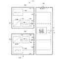
図5は、ネットワーク64用に複式のコントローラおよび電源構成を形成する仕方で単一の端子ブロック74Rへ接続されるカード72A,72Bと名付けた図4の電源デバイス一体化バスコントローラ72のうち2つを示す。特に、図5の複式構成は単一のバスセグメント64に対し複式の電力供給およびコントローラ機能を提供する。図5から特記されるように、カード72A,72Bは図4のものと同一であり、簡単な構成の端子ブロック74Rを用いて複式構成へ簡単に接続することができる。より具体的には、主バスコントローラおよび電源デバイス72Aはデバイス72Aの出力端88Aに接続された主バスコントローラ80Aを含んでおり、またダイオード92Aを介してデバイス72Aの電力出力端90Aへ接続する主電源82Aを含んでいる。同様に、バックアップ用のすなわち副電源デバイス一体化バスコントローラ72Bは、デバイス72Bの出力端88Bに接続されるバックアップ用バスコントローラ80Bを含むとともに、ダイオード92Bを介してデバイス72Bの電力出力端90Bに接続されるバックアップ用電源82Bを含んでいる。複式端子ブロック74Rは、主および副の電源デバイス一体化バスコントローラ72A,72Bのそれそれの2個の出力のそれぞれを受け入れる入力端を含んでいる。
FIG. 5 shows two of the power device integrated
図5に示すように、端子ブロック74R内の回路系は例えば(端子ブロック74Rの出力端94に接続された)フィールドバスセグメントバス64を両方のデバイス72A,72Bの制御線路へ直接接続している。加えて、端子ブロック74Rは主電源82Aと副電源82Bからの電力信号を(デバイス72A,72B内の複式化ダイオード92A,92Bを電力信号が通過した後で)併せ接続し、この複合電力信号を端子ブロック74R内に配置されたインピーダンスデバイス98の入力端へ給送する。インピーダンスブロック98の出力端は、出力端94を介してセグメント64へ直接接続してある。ここで、インピーダンス回路98は図4の端子ブロック74について説明したものと同じ回路とすることができ、かくして非複式構成内で使用されるのと同じインピーダンス回路98とすることができる。この場合、複式端子ブロック74Rは、電源デバイス一体化バスコントローラ72A,72Bが(図5に示すように)複式構成にて接続されているか、あるいは(図4に示すように)単式あるいは非複式構成にて接続されているかによらず、セグメントバス64に対し同じ逆方向インピーダンスを供給する。
As shown in FIG. 5, the circuit system in the
図4の単式端子ブロック74と同様、複式端子ブロック74Rはユーザが選択可能な高信頼性終端ネットワーク100をその中に含んでおり、これをネットワークセグメント64にとって終端ネットワークが必要かどうかに基づき所望に応じてオンまたはオフすることができる。理解されるように、複式端子ブロック74Rと単式端子ブロック74との間の主な差異は、基本的には、複式端子ブロック74Rがそこに接続すべき2つの電力供給信号および2個の制御信号を見込む追加の入力端を含んでおり、冗長端子ブロック74Rが図5に示すようにブロック74R内でコントローラ信号および電源信号を複合するとの事実に存する。その結果、複式端子ブロック74Rは単に例えば副電源デバイス一体化バスコントローラ72Bに関連する入力端を用いないことにより、単式構成内で使用することができる。いずれにせよ、図5の複式構成では、主電源デバイス一体化バスコントローラ72Aの電力供給出力端は共通端子ブロック72R内部の副電源デバイス一体化バスコントローラ72Bの電力供給出力端へ接続する。共通バスインダクタ98により、バスインピーダンスは選択された複式あるいは単式の構成とは無関係に常に正規の最適なバスインピーダンスおよび終端処理を提供する。さらに、バス・インピーダンス・インダクタ98はより高い信頼性に合わせ設計することができる(例えば、ラッカーを塗布し、かつ半田接合に起因する故障を排除するため複式ピンを用いてPCBに接続するインダクタから形成することができる)。ユーザが選択可能な終端器100は、複式構成要素を用いる高信頼性設計とすることもできる。
Similar to the
図6は、図4の電源デバイス一体化バスコントローラ72のより詳細なブロック線図を示すものである。特に、図6の電源デバイス一体化バスコントローラは、診断動作を遂行し、かつデバイス72の単一の筺体86内に一体化したバスコントローラ80と電源82の両方の動作について他の情報を提供する機能を含んでいる。図示のように、一体化カード72はバスコントローラ80および電源82を含んでいる。ここで、コントローラ80は直流12ボルト電力信号を受け取って外部電源からバスコントローラ80へ給電し、例えばプロセスコントローラ(例えば、図1のプロセスコントローラ12)へ接続することのできるバックプレーンバスや他の入/出力デバイス等へ接続する。
FIG. 6 shows a more detailed block diagram of the power device integrated
電源82は外部直流24ボルト電力信号を受け取り、この信号を用いてバス64へ供給するバス電圧を生成し、加えてデバイス72内の幾つかの回路系に給電するのに用いる直流5ボルト信号あるいは他の電力信号を生成する。電源82が生成するバス電圧は、電源82から流出する電流を検出するよう作動する電流検出モジュール110を介して供給される。電流検出モジュール110は電流計測信号を生成して診断監視マイクロコントローラ112に供給し、これが電源82の監視診断制御を提供すよう動作する。特に、マイクロコントローラ112はデバイス72内で診断を行い、バス64への適切な電流の流れ、すなわち電流検出モジュール110の出力に基づき設定されあるいは査定範囲内での電流の流れを保証することができる。バス電力信号は電流検出モジュール110を介して出力制御スイッチ114へも供給され、このスイッチは診断監視マイクロコントローラ112の制御下で任意の所望種の切り替え回路系とすることができる。出力制御回路114の出力は、出力電圧計測値あるいは電圧検出値として診断および監視マイクロコントローラ112へ供給し戻される。
The
電源82が生成する直流5ボルト信号により給電される診断および監視マイクロコントローラ112は、電流検出モジュール110が供給する電流計測値と、スイッチ114の出力端に供給される電圧計測値とを用い、いずれも電源82内の故障あるいは問題により引き起こされることのある電流過負荷、低電圧や高電圧、変動電圧等の電流および電圧問題を検出する。これらの計測値に基づき、診断監視マイクロコントローラ112は出力制御スイッチ114へ出力を供給し、電源82からカード72の電力出力端90への電流の流れや電圧を切り替えあるいは阻止することができる。従って、診断および監視マイクロコントローラ112はデバイス72内の被検出状態に基づきカード72の出力端90へダイオード92を介して電力が流れるのを阻止するよう作動させることができる。
The diagnostic and
さらにまた、診断および監視マイクロコントローラ112は発光ダイオード(LED)118を駆動する出力を供給することができ、このダイオードはカード72の筺体86を透かして視認し、デバイス72内の電力供給システムの作動状態を示すことができる。従って、一実施例では、診断および監視マイクロコントローラ112は、電源82がカード72の出力端90へ電力を適切に供給するよう作動しているときは常にLED118を点灯させることができ、問題が起きたときや電源82が適切に作動していないときにLED118を消灯することができる。
Furthermore, the diagnostic and
さらにまた、診断および監視マイクロコントローラ112は電源82の故障を指示する1以上の信号あるいは他の診断情報を、絶縁回路120を介してコントローラ80へ供給することができる。絶縁回路120は、例えば光学式の絶縁回路あるいは他の任意種の絶縁回路とすることができる。この絶縁回路120の主目的は、デバイス72により実装される2つの異なるチャネル間の漏話を防止し、一方のチャネルからの電力信号あるいはデジタル信号がノイズとして他方のチャネル内へ流出しないようにすることにある。いずれにせよ、マイクロコントローラ112は出力電圧や出力電流やハードウェア状態(例えば、基準電圧)を監視することで電源の機能を診断する監視を行うことができ、この診断情報は離散する光学的に絶縁された出力端により筺体86内のコントローラ80の離散する入力端へ通信することができる。コントローラ80への出力をトリガーすることのできる状態には、過小電圧や過大電圧、過大電流、ハードウェアの機能不全等の検出を含めることができる。故障状態は、ナムール(Namur)規格NE44に従い赤色LED118(その1つは電源チャネルごとに配設される)を用いて指示することもできる。電源システムの設計は、デバイス72上のシリアルインタフェースを用いて離散出力を供給できるようにもしてある。この機能をデバイス72上に実装し、任意の所望時間にデバイス72からの詳細な診断情報(例えば、総出力電流)へ監視システムがアクセスできるようにすることができる。
Furthermore, the diagnostic and
マイクロコントローラ112とプロセッサコントローラ80との間の通信は同じデバイス筺体86内で行われ、マイクロコントローラ112が供給する診断情報に基づきバスコントローラ80がより良好に作動できるようにする。特に、バスコントローラ80はカード72の同一筺体内の電源回路系から直接に診断情報を受け取り、それによってこの情報をより迅速に受け取り、例えばバックアップ用バスコントローラを切り替えたり、マイクロコントローラ112からの診断情報に基づき必要に応じてバス64上で他の何らかの行動をとったりするべく、この情報に基づき迅速に作動させることができる。さらに、コントローラ80は例えばユーザをコントローラ80へ接続するバックプレーンバスあるいは他のネットワークを介してユーザに問題を通知することができる。さらにまた、バスコントローラ80は筺体86内の電源82に代わって外部電源から給電されるため、バスコントローラ80はたとえ関連する電源82が故障したときでも動作を継続することができる。
Communication between the
図6に示すように、バスコントローラ80はもうひとつの絶縁回路122を介して電圧モードフィールドバス媒体取着ユニットあるいは媒体アクセスユニット(MAU)124とも通信し、MAUはコントローラ80により生成されあるいはこれに送信された信号に対し電圧モード診断や他の動作を行う。MAU124は、実質的にバスプロトコル通信の物理層を実装している。ここでも、電圧モードMAUはバスコントローラ80および電源82と同じ筺体86内に配置され、電源82から(5ボルト線路上で)電力を受け取る。電圧モードMAUの機能は、それ故にコントローラ80と電源82の動作および関連する診断とに緊密に結び付けて調整される。いずれにせよ、コントローラ80とバス64との間を流れる信号は、電圧モードフィールドバスMAU124を介しあるいはこれを用いて供給される。
As shown in FIG. 6, the
重要なことは、多くのH1コントローラカードに現在用いられている電流モードMAUとは対照的に、電圧モードMAU124の使用はデバイス72内で吸収される電力を低減し、デバイス72をして十分に放熱させ、図6に示す全ての構成要素を共通筺体86内に配置させることを可能にできる。特にフィールドバスシステムにあっては、フィールドバス電圧とは無関係の12mAの平均電流消費を伴う電圧モードMAUを用いることができる。この動作は、結果として、30ボルトのバス電圧において、フィールドバスMAU内で最大720mWの電力を消費する。この場合、単一の内部5ボルト電源により給電される電圧モードMAUは、標準的な構成要素に依拠させることができる。さらに、この種の離散MAUは送信側のFF−831フィールドバス仕様に合致し、受信側の具体的なジッター許容限界を一般に2倍上回る(3.2psでなく6.4ps)。いずれにせよ、通常の電力消費は最大で電流モードMAU内で消費される1/3未満となる。その結果、電圧モードMAUの使用がデバイス72内部での電力消費を1つの事例で約400mW低減する。この事実は、出力電流の増大および性能改善を同時に可能にするものである。電圧モードMAUの使用は、筺体86内の必要な基板面積を著しく低減することもできる。
Importantly, in contrast to the current mode MAU currently used in many H1 controller cards, the use of the
上述のように、診断および監視マイクロコントローラ112や電流検出部110や出力制御スイッチ114や複式化結合回路92やLED118を含め、バスコントローラ80と電源82の両方に関連する全ての回路系を、筺体86内の1個の回路基板上に配置するか、あるいはこれに接続することができ、一方でコントローラ80を、また所望とあらば電圧モードフィールドバスMAU124をデバイス72の筺体86内の第2の回路基板上に配置することができる。ここで、図2のシステムに必要とされるデバイス接続路のための外部デバイスを必要とすることなく、同一筺体内に併せ接続した異なるデバイスどうしの近接が、電源と制御デバイスとの間のより高速の送信をもたらし、また単一コントローラに専用の単一電源を提供し、それがこれら2つのデバイスを、ユーザが設定する異なる構成に基づき別個に接続する必要のある個別筺体あるいは個別カード内にこれらデバイスを持たせるよりも良好に併せ動作させられるようにする。さらに、電源診断は電源およびバスコントローラと同じデバイス内にあり、診断をデバイス自体へより密接に結び付ける。さらにまた、これら3個のユニットを単一の筺体内、特に図2のコントローラ専用カード52と実質同じ大きさを有する筺体内に一体化することで、先行技術構成に関連する収容ケースならびに空間を縮減するが、それはI/O通信ネットワークの設定に必要な端子ブロックの数だけでなく必要とされる個別ハードウェアデバイスの数もまた低減するからである。概して、カード72あるいは筺体86は一般のコントローラカードと同じ大きさとなり、一般のコントローラカードと同じ収容ケース内へ摺動挿入されることになる。特に、カードはほぼ深さ4インチ、高さ6インチ、幅1/5インチとすることができる。
As described above, all circuit systems related to both the
理解されるように、バスコントローラ80はフィールドバスセグメントバス64の形をとる第1の網路バスとプロセスコントローラ12へのネットワーク接続(図1)を確立するバックプレーンバスの形をとる第2の網路バスとの間のインタフェースデバイスとして作動する。バスコントローラ80はかくして、第1の網路バス64上でバス依拠通信信号を供給すべく第1の網路バス(バス64)へ接続するための第1の入/出力線路を含んでおり、また第2の網路バス(すなわち、プロセスコントローラ12へ接続されたバックプレーンバス)へ接続するための第2のコントローラ入/出力線路を含んでいる。加えて、理解されるように、デバイス72は筺体86を挿通して配置した第1の物理的ネットワークインタフェースを含んでおり、これが第1のバスコントローラ入/出力線路とバス64との間に適当な電気的接続をもたらす。この第1の物理的ネットワークインタフェースは、端子88および/またはMAU124により形成することができる。デバイス72は筺体86を挿通して配置された第2の物理的ネットワークインタフェースもまた含んでおり、これが第2のバスコントローラ入/出力線路と第2の網路バス(例えば、バックプレーンバス)との間の電気的接続を提供する。これらの接続路ならびにインタフェースを用いることで、バスコントローラ80はインタフェースデバイスとして作動し、バックプレーンバスから網路バス64へ、あるいはその逆に信号を転送し、これらの信号をこれら各網路バス上の適当な通信プロトコルに乗せ、必要に応じて他の通信動作を行なう。従って、バスコントローラ80はバス64上のデバイスがコントローラ12と通信できるよう、またその逆もできるよう作動する。
As will be appreciated, the
図7は、端子ブロック174に接続された電源デバイス一体化バスコントローラ172の第2の実施形態の一般化されたブロック線図を示すものである。この場合、電源デバイス一体化バスコントローラ172はバスコントローラ出力端に接続したバスコントローラ180と、複式化回路要素(例えば、ダイオード)192を介して電源出力端190へ接続した電源182とを含んでいる。しかしながら、この場合、インピーダンスデバイス198はデバイス172の筺体186内にも配設され、電源182とダイオード192との間に配置される。図7に示すように、単式端子ブロック174は出力端190に配設された電源線路を出力端188に配設されたバスコントローラ線路に直接接続し、これら信号の両方を網路バスあるいはセグメント64に直接接続する結線を含む。単式端子ブロック174には、所望とあらばバス64に選択的に接続することのできるユーザが選択可能な高信頼性終端ネットワーク100を含めることもできる。図7の構成は、インピーダンスデバイス198が電源デバイス一体化バスコントローラ172の筺体186内に配置されており、端子ブロック174を簡単化し、デバイス172からネットワーク64への接続を非常に簡単にするが、それは端子ブロック174が基本的には2個の出力端188,190を併せバス64に直接接続するからである。事実、所望とあらば、この構成は、バスコントローラ180の出力端を筺体186内のダイオード192の出力端に接続し、かくして一体化デバイス172が電力信号と制御信号の両方をその上に有する単一の出力端を端子ブロック174に配設するようにすることで、さらに簡単化しうる。この単一の出力端はそこで、端子デバイス174上の単一の入力端を介してバス64と端子ブロック174内の終端ネットワーク100とに接続し、それによって端子ブロック174をさらに簡単化しうる。無論、図7の電源デバイス一体化バスコントローラ172は図6に示した診断素子や他の要素を含ませることができ、コントローラ180と電源182とダイオード192とインピーダンスデバイス198は、図4〜図6について記載した対応要素と同じにできる。
FIG. 7 shows a generalized block diagram of the second embodiment of the power device integrated
図7の電源デバイス一体化バスコントローラ172と端子ブロック174は単式ネットワーク構成構成では良好に作動するが、一体化デバイス172は図8に示す複式構成内に接続することもできる。特に、図8の複式構成は、図7のデバイス172と同じ要素を有する電源デバイス一体化バスコントローラ172のうち2つ(デバイス72A,172Bと書き表す)を含んでいる。しかしながら、ここで複式端子ブロック174Rは、デバイス172A,172Bの出力端190A,190Bにおいて電力供給線路へ接続してあり、またデバイス172A,172Bの出力端188A,188Bにおいてバスコントローラ信号線路を相互にかつセグメントあるいはバス64へ直接接続してある。加えて、端子ブロック174Rは所望に応じてバスあるいはセグメント64に接続することのできるユーザが選択可能な高信頼性終端ネットワークを含んでいる。
Although the power device integrated
受動インダクタ、例えば5mHインダクタを用いて(図7の)バス・インピーダンス・デバイス198と(図8の)バス・インピーダンス・デバイス198A,198Bを用いることも有利であると考えられる。何故なら受動インダクタの信頼性は、熱応力を受ける直列トランジスタを有する演算増幅器により制御されるジャイレータ回路の信頼性と比べてずっと高いからである。さらに、図8の並列複式設計にてジャイレータ回路を使用するときは、2個のジャイレータのそれぞれに監視回路を配設する必要もあろう。さもなくば、1個のジャイレータ回路内の短絡故障はたとえシステムが冗長型であろうとも、バスインピーダンスの損失に通ずることになる。特に、短絡とともに故障したジャイレータは作動中のジャイレータと比べてより少ない電圧降下を生じ、そのため、故障したジャイレータを有する電源の出力端での複式ダイオードが導通し、従って、作動中の健全なジャイレータ回路を短絡させることになる。バス・インピーダンス・デバイス用の受動インダクタネットワークの使用が、この問題を取り除く。
It may also be advantageous to use the bus impedance device 198 (of FIG. 7) and the
いずれにせよ、電源デバイス一体化バスコントローラ172が単式構成(図7に示す)にて稼働している限り、バス64は1個のインピーダンスインダクタをもって給電される。しかしながら、図8のもののような冗長構成にあっては、バス64は互いに並列に配置された2個のインピーダンスインダクタを有する回路により給電される。特に、デバイス172A,172Bからの電力信号線路がバス・インピーダンス・デバイス198A,198Bの後方で互いに接続されているため、バス・インピーダンス・デバイス198A,198Bは互いに並列に接続される。その結果、受動インピーダンス回路系により実装した場合、インピーダンスデバイス198A,198Bは、図8の複式構成において構成したときの電源182A,182Bからのバスあるいはセグメント64に対し、図7の単式構成において構成された単一デバイス172に関連する単一電源182からのセグメント64に提示されるインピーダンスとは異なるインピーダンスを呈する。より具体的には、図7のデバイス172の構成は、複式構成にて使用するときに両インピーダンスインダクタが並列に作動してバスのインダクタンスが単式構成におけるその値の僅か半分となるという犠牲を伴うものとなる。特に、デバイス198A,198Bのインピーダンスが互いに等しいと仮定すると、図8の複式構成におけるネットワーク64から見たインピーダンスは、(図8のインピーダンスデバイスの並列接続のため)図7の単式構成におけるネットワーク64から見たインピーダンスの約半分となろう。
In any case, as long as the power device integrated
インピーダンス差を補正しあるいは補償すべく、デバイス198Aのインピーダンスはネットワーク64から見たインピーダンスを図8の冗長構成において図7の単式構成におけるのと同じにするよう可変しあるいは変更可能にすることができる。他方で、インピーダンスデバイス198A,198Bのインピーダンスは、ネットワーク64から見たインピーダンスが複式構成と単式構成とで異なる一方で、両方の場合に見られるインピーダンス値が電源182A,182Bに対し適切な濾波を提供し、単式構成と複式構成の両方においてシステムの適切な信号調整操作を規定するのに十分となるよう選択することができる。より具体的には、フィールドバス実施形態では、複式モードだけでなく単式モードにおいてもFF−831仕様の要件に応えるべく、バス・インピーダンス・インダクタの値と終端器100の値を選択する際に妥協が必要となる可能性がある。特に、デバイス198の電力供給インダクタンスを5mH超の値(例えば、6〜7mH)へ増大させ、複式構成において得られるインダクタンス値が依然として許容範囲である3〜3.5mH内にあるよう保証することが必要かも知れない。信号品質をさらに調整するには、複式構成での終端デバイス100における終端抵抗あるいは終端容量を増大させ、明確に定義された5mHバスインピーダンスの欠如を補償することが望ましいようである。しかしながら、この操作は、端子ブロック174R内の端子デバイス100が固定されることを概ね要求するが、それはユーザが供給する外部終端器デバイス100の使用を許可することで、終端インピーダンスの値が供給元の管理を逸脱することになるからである。いずれにせよ、電源デバイス一体化バスコントローラ172を単式構成と複式構成の両方で使用可能とする要件は、結果として、バスインピーダンスと、得られる信号品質とに対して妥協することとなる。
To correct or compensate for the impedance difference, the impedance of
図9は、単式構成と複式構成の両方において電源とのインピーダンス整合を可能にする電源デバイス一体化バスコントローラ272のさらに異なる実施形態を表わすものである。図9に示すように、電源デバイス一体化バスコントローラ272は単式端子ブロック272へ接続してある。デバイス272は、デバイス272の出力端に接続したバスコントローラ280と、複式化ダイオード292を介してデバイス272の電力供給出力端290に接続した電源282とを含んでいる。さらに、インピーダンスデバイス298は、受動インダクタネットワークとすることができるが、例えばデバイス272の筺体286を挿通させて配置した入/出力端子300,301に接続する2個の端子を有するデバイス272内に配置する。図9に示すように、単式構成では、デバイス272内の電源280の出力端は入力端子300へ直接戻して接続され、それ故に端子ブロック274内の接続路を介してインピーダンスデバイス298の入力端に接続される。同様に、この単式構成にあっては、インピーダンスデバイス298の出力端はデバイス272の出力端子301を通じ端子ブロック274内の接続路を介してバスあるいはセグメント64に直接接続される。ここでも再び、端子ブロック274にユーザが選択可能な高信頼性終端ネットワーク100を含ませることもできる。図9の構成では、インピーダンスデバイス298は電源デバイス一体化バスコントローラ272の筺体286内に配置し、端子ブロック274の接続と用途を簡単に構成できるようにし、端子ブロック274が最小の構成要素を有することができるようにしてある。無論、図9の電源デバイス一体化バスコントローラ272には図6に示した診断要素と他の要素と、コントローラ280とを含ませることができ、電源282とダイオード292とインピーダンスデバイス298は図4〜図6について説明した対応要素と同一とすることができる。
FIG. 9 represents yet another embodiment of a power device integrated
図10の複式構成では、電源デバイス一体化バスコントローラ272A,272Bのうち2つが、図9の端子ブロック274とは異なる構成の異なる端子ブロック274Rに接続してある。デバイス272A,272Bの要素は、図8のデバイス272のものと同じであるが、A又はBの呼称を用いて指示してある。重要なことは、端子ブロック274Rが単一のインピーダンスデバイス298Rを含んでいて、これをデバイス272A,272B内のインピーダンスデバイス298A,298Bと同じ大きさにできる点にある。この複式構成にあっては、デバイス272A,272B内のインピーダンスデバイス298A,298Bは未使用のままであり、その代わりに電源282A,282Bの出力端が端子ブロック274R内のインピーダンスデバイス298Rの入力端へ併せ接続される。この場合、電源282A,282Bは(図9におけるように並列接続されたインピーダンスデバイスを介する代わりに)単一のインピーダンスデバイスを介して接続されるため、ネットワーク64は図9の単式構成と図10の複式構成の両方において同じインピーダンスを見ることになる。無論、図10の冗長端子ブロック274Rには、バス64へ選択的に接続することのできるユーザが選択可能な高信頼性終端ネットワーク100を含めることができる。図9と図10の構成は、異なる端子ブロック274と274Rを単式状況と複式状況に用いるよう規定する一方で、両状況において同一のインピーダンスを規定し、従ってバスあるいはネットワーク64上への電力供給について電源デバイス一体化バスコントローラ272A,272bのより信頼できる、すなわち最適な操作を保証する。
In the duplex configuration of FIG. 10, two of the power device integrated
図11A〜11Cは、バス終端デバイス100を図4〜図10のいずれかの構成に配設したり、そこで使用したりすることのできる3通りの異なる態様を示すものである。特に、図11A〜11Cは、バスセグメント64用にユーザが選択可能なバス終端デバイス100を実装するのに利用可能な3つの概念を示すものである。図11Aは、端子ブロック74上の2個の端子間あるいはそこに横断配置した2個の端子ねじ込み式リンクあるいはジャンパー線400の使用を示すものである。この場合、端子ブロック74上の各チャネルごとの2個の未使用の端子を組み込み式終端ネットワーク100(図11Aに図示せず)の賦活化に用いることができ、この賦活化は外部ジャンパー線400を用いて着手し、組み込み式終端デバイス100をバス64へ接続することができる。ジャンパー線400の使用が、高信頼性終端ネットワーク100の作動状態を明確に視認可能とする。所望とあらば、リンクあるいはジャンパー線400を初期設定として実装することができ、ユーザから要求された場合に取り除くことができる。この場合、端子ブロック74に高信頼性の受動構成要素だけ含ませることができる。
11A-11C illustrate three different modes in which the
図11Bは、端子デバイス100としてのねじ込み式の被覆成型外部終端器402の使用を示すものである。この場合、端子デバイス100の終端回路系は外部終端器402内に配置されていて、端子ブロック74上の端子ポストを介してバス64へ直接接続される。バスセグメントは端子ブロック74上に4個の端子(2個の(+)端子と2個の(−)端子)を有しており、端子デバイス402(概ね抵抗やコンデンサ等の受動構成要素しかその上に有していない)は2個の個別チャネルごとに端子デバイスを実装することができる。4個の分岐終端器402は、電源カード一体化バスコントローラが中継回線の始端に組み込まれている場合に未使用端子へ接続することができ、ここでは端子ブロック74上のねじ込み端子のうち2個が未使用のまま残ることになる。この場合、外部から組み込まれた終端器デバイス402は高信頼性であり明瞭に視認可能とされる。
FIG. 11B illustrates the use of a screw-on coated molded
図11Cは、ロータリスイッチ404(その起動メカニズムしか図示していない)が端子ブロック74上あるいはその内部に配置され、内部終端デバイス100(図11Cには図示せず)をバス64へ接続するのに用いる事例を示すものである。ロータリスイッチ404の起動は、内部終端デバイス100をバス64に対し接続しあるいは分離するのに用いることができる。この随意選択肢はより視認しづらく、それ故に信頼性が劣るものであり、特に端子ブロック74の使用がG3規格準拠(すなわち、腐食性の高い環境での操作)を要求するときにそうである。
FIG. 11C illustrates that a rotary switch 404 (only its activation mechanism is shown) is disposed on or within the
本願明細書に開示する電源デバイス一体化バスコントローラの設計は、フィールドバスH1ネットワーク等のバス給電ネットワークについての一般的な設計要件に合致するよう実装することができ、その一方で一般のコントローラ専用デバイス(例えば、一般のH1バスコントローラ専用カード)の許容限界内での放熱負荷が達成される。さらに、単式構成ならびに複式構成の両方についてのこれらの設計は、これらのネットワークに対し周知のデバイスを上回る信号品質や耐性や熱負荷の影響を及ぼすことなく行なうことができる。事実、これらのデバイスのより低い電力消費により、制御室の収容ケース内部の実装密度の増大が可能となり、従って、コンパクトな設計が制御室の収容ケース空間を節減する。さらにまた、受動電力調整ユニット(例えば、デバイス98,198,298用の受動インダクタネットワーク)の使用により、長期の耐用年数が保証され、かつ信頼できるデータ伝送に向けた最良のフィールドバス信号が保証される。さらにまた、これらの設計は、これらのデバイスのファームウエアに対する変更や改変を一切要求されずに既存のH1バスコントローラ専用カードの電気的設計に基づいてこれを使用することで、フィールドバス設計に実装することができる。
The power device integrated bus controller design disclosed herein can be implemented to meet general design requirements for bus powered networks such as fieldbus H1 networks, while general controller dedicated devices. A heat radiation load within the allowable limit of (for example, a general card dedicated to the H1 bus controller) is achieved. In addition, these designs for both single and dual configurations can be made to these networks without the impact of signal quality, immunity, and thermal loading over known devices. In fact, the lower power consumption of these devices allows for increased mounting density inside the control room containment case, and thus a compact design saves control room containment space. Furthermore, the use of a passive power conditioning unit (eg, a passive inductor network for
さらにまた、フィールドバス実装にあっては、一般のH1バスコントローラ専用カードの大きさを上回るデバイス筺体の大きさの際立った変更を招くことなく設計を行なうことができる。何故なら電源の追加は、筺体の大きさの変更を必要とする仕方で複合デバイス内の電力消費を増大させることなく可能だからである。かくして、本願明細書に記載する例えば電源デバイス一体化バスコントローラ72,172,272は、ほぼ4インチ×6インチ×1.5インチの大きさの筺体内のフィールドバスネットワークに実装することができる。
Furthermore, in the field bus mounting, the design can be made without causing a noticeable change in the size of the device housing that exceeds the size of a general card dedicated to the H1 bus controller. This is because the addition of a power supply is possible without increasing the power consumption in the composite device in a way that requires a change in the size of the enclosure. Thus, for example, the power device integrated
一般の既存のフィールドバスH1バスコントローラ専用カードによる電力消費は、3ワットである。この電力は、現行のあるいは典型的なフィールドバスH1バスコントローラ専用カードの筺体の内部で完全に消費される。さらに、既存のMAUはH1バスから給電され、MAU内の平均電流は12mAとなる。この電力もまたH1バスコントローラ専用カードの筺体内部で完全に消費され、MAUが引き起こす総電力消費はVFB×2×12mA(例えば、28Vで672mW)として算出される。ここで、フィールドバスH1バス・コントローラ・カード筺体内の最大許容総電力消費は、70℃の周囲温度において、7.5ワットである。これらの放熱設計規範には、本願明細書に記載する新規の電源デバイス一体化バスコントローラを用いて応えることができる。さらに、フィールドバスH1バスコントローラ専用カードの既存の実装はセグメントごとに1個の離散入力端を配設するものであり、これらの入力端を本願明細書に説明する新規の一体化設計により使用し、電源から故障状態を発信させることができる。 Power consumption by a general existing fieldbus H1 bus controller dedicated card is 3 watts. This power is completely consumed inside the current or typical fieldbus H1 bus controller dedicated card housing. Furthermore, the existing MAU is powered from the H1 bus, and the average current in the MAU is 12 mA. This power is also completely consumed inside the H1 bus controller card, and the total power consumption caused by the MAU is calculated as VFB × 2 × 12 mA (eg, 672 mW at 28V). Here, the maximum allowable total power consumption in the fieldbus H1 bus controller card enclosure is 7.5 watts at an ambient temperature of 70 ° C. These heat radiation design rules can be met by using the new power supply device integrated bus controller described in this specification. In addition, existing implementations of fieldbus H1 bus controller dedicated cards provide one discrete input for each segment, and these inputs are used with the new integrated design described herein. The failure state can be transmitted from the power source.
電力消費と信号品質とに加え、回路空間は本願明細書に説明する電源デバイス一体化バスコントローラの設計にあっては重要な問題である。通常のフィールドバスH1バスコントローラカード筺体内の7.5ワットの最大電力消費が、カード筺体内部での70℃〜85℃の温度上昇に通ずるものと想定することにする。さらに、バスコントローラ回路には約3W(12V×250mA)の平均電力消費を想定する。バスコントローラカードの2個の一体化フィールドバスMAUはそれぞれ、フィールドバスネットワークから12mAの電流を引き出し、両フィールドバスMAUについて、カード筺体内部において、フィールドバス電圧28Vで0.672W、30Vで0.72Wの追加の電力消費をもたらす。このため、2個の一体化フィールドバス電源のそれぞれについての最大電力消費は、出力電圧28V供給時に1.914W、出力電圧30V供給時に1.89Wほどの大きさとなる可能性がある。従って、本願明細書に提示する共通電力調整インピーダンス設計は450mAの最大出力電流にて28〜30Vの出力電圧を生成し、フィールドバスセグメントに供給する12.6Wの最小電力をもたらす。電源カード一体化バスコントローラ筺体内部の最大生成電力消費は約7.18Wであり、そのうちの2×1.93Wが診断を含むフィールドバス電力供給に用いられ、2×0.16Wが電圧モードMAUに用いられ、3Wがバスコントローラ回路に用いられる。これは、カード筺体内での7.5W許容最大電力消費まで約320mWの余裕を残すものである。端子ブロック内部の最大電力消費は、約0.53W(2×1.3Ω×450mA2)となる。電源の出力電圧は、IEC60079−15規格とIEC60079−11規格に従い32Vへ安全に制限される。この限界は、電圧制限構成要素に対し安全係数を適用し、要素配置図において、適用可能な距離を適用することで達成することができる。この構成により、Ex_icあるいはEx_nL等級の用途向けに承認されたセグメントプロテクタを組み合わせた電源カード一体化コントローラの使用も可能になる。 In addition to power consumption and signal quality, circuit space is an important issue in the design of the power device integrated bus controller described herein. Assume that a maximum power consumption of 7.5 watts in a normal fieldbus H1 bus controller card enclosure leads to a temperature rise of 70 ° C. to 85 ° C. inside the card enclosure. Further, an average power consumption of about 3 W (12 V × 250 mA) is assumed for the bus controller circuit. Each of the two integrated fieldbus MAUs of the bus controller card draws a current of 12 mA from the fieldbus network, and both fieldbus MAUs have a fieldbus voltage of 28V at 0.672 W and 30 V at 0.72 W within the card housing Brings additional power consumption. For this reason, the maximum power consumption of each of the two integrated fieldbus power supplies may be as large as 1.914 W when the output voltage is 28 V and 1.89 W when the output voltage is 30 V. Thus, the common power regulated impedance design presented herein produces an output voltage of 28-30 V at a maximum output current of 450 mA, resulting in a minimum power of 12.6 W delivered to the fieldbus segment. The maximum generated power consumption inside the power card integrated bus controller housing is about 7.18W, of which 2 × 1.93W is used for fieldbus power supply including diagnosis, and 2 × 0.16W is used for voltage mode MAU 3W is used for the bus controller circuit. This leaves a margin of about 320 mW up to the 7.5 W allowable maximum power consumption in the card housing. The maximum power consumption inside the terminal block is about 0.53 W (2 × 1.3Ω × 450 mA 2 ). The output voltage of the power supply is safely limited to 32V according to the IEC 60079-15 and IEC 60079-11 standards. This limit can be achieved by applying a safety factor to the voltage limiting component and applying an applicable distance in the element layout. This configuration also allows the use of a power card integrated controller combined with segment protectors approved for Ex_ic or Ex_nL grade applications.
フィールドバスネットワークについての標準的な電力供給効率は、室温24V入力電圧において、通常90%である。最悪の事例の効率は、19.2〜35ボルトの特定入力電圧範囲と−40℃〜70℃の温度範囲について約87.5%である。電源カード一体化バスコントローラ筺体に電力調整インダクタが組み込まれている場合、カード電力消費の算出時に電力調整インダクタの電力消費を考慮する必要がある。このことは、電力調整インダクタが端子ブロック内に組み込まれている場合には当てはまらない。
Typical power supply efficiency for fieldbus networks is typically 90% at
電力調整インダクタが筺体内に配置してある事例については、電力調整インダクタの直列抵抗は調整コイルの大きさに応じて通常は1Ω(温度により±30%の幅がある)である。下記の表1は、電源一体化バスコントローラにとって妥当な出力電圧/電流の組み合わせについての幾つかの実例を与えるものである。記載した損失は、電源一体化バスコントローラ筺体内部の損失である。 In the case where the power adjustment inductor is disposed in the housing, the series resistance of the power adjustment inductor is usually 1Ω (with a width of ± 30% depending on the temperature) depending on the size of the adjustment coil. Table 1 below gives some examples of output voltage / current combinations that are reasonable for a power integrated bus controller. The described loss is a loss inside the power controller integrated bus controller housing.

表1から見てとれるように、電力調整インダクタ(すなわち、インピーダンスデバイス98)をカード72の筺体内に配設したときに筺体内の十分な放熱をもたらすことが可能である。
As can be seen from Table 1, it is possible to provide sufficient heat dissipation within the housing when the power regulating inductor (ie, impedance device 98) is disposed within the housing of the
上述のように、能動ジャイレータ回路の使用や5mHインピーダンスの受動インダクタの使用を含め、ACバス信号に対しDC電圧を減結合させるべく電源内には適当なフィールドバスインピーダンスを生成する2つの汎用概念が存在する。能動ジャイレータ回路は、たとえバス上に1個しか終端器100が作動状態にない場合でも、容認可能なバスインピーダンスを提供するため約2.5ボルトの典型的電圧降下を必要とする。十中八九、標準的な回路は特により高い電流要求時にさらに高い電圧降下を必要とする。この事実は、結果として、0.16W(1Ω×400mA2)の5mH受動インダクタ内のずっと少ない電力消費とは対照的に、能動ジャイレータ回路では1W(2.5V×400mA)の典型的な電力損失を引き起こす。
As mentioned above, there are two general concepts that generate the appropriate fieldbus impedance in the power supply to decouple the DC voltage to the AC bus signal, including the use of an active gyrator circuit and the use of a 5mH impedance passive inductor. Exists. An active gyrator circuit requires a typical voltage drop of about 2.5 volts to provide an acceptable bus impedance, even if only one
さらに、共通バスインピーダンス構成により1個のインダクタが節約される(インダクタはコストに対し際立って寄与する)。共通バスインピーダンスと並列バスインピーダンスの両方の信号品質は優れており、結果として電力の利用可能性は両方の受動構成とも高いものとなる。冗長な半田接続を有する共通バス・インピーダンス・インダクタの使用は、電力調整器の高インピーダンス欠陥に関し冗長なインダクタを用いるのと同じ効用をもたらす。しかしながら、1個のインダクタの巻線内短絡は必ずバス通信の妨害を引き起こす。何故なら並列バスインピーダンス構成内で1個のインダクタが短絡故障した場合に生成されるインピーダンスはゼロとなるからである。インダクタコアの巻線内短絡あるいは機械的亀裂の確率は、並列のバスインピーダンス構成を用いるのとは対照的に、共通バスインピーダンス構成を用いたときはたった半分となる。 In addition, a common bus impedance configuration saves one inductor (the inductor contributes significantly to cost). The signal quality of both the common bus impedance and the parallel bus impedance is excellent, and as a result, the power availability is high for both passive configurations. The use of a common bus impedance inductor with redundant solder connections provides the same benefits as using redundant inductors for high impedance defects in power regulators. However, a short in the winding of one inductor always causes interference with bus communication. This is because the impedance generated when one inductor short-circuits in the parallel bus impedance configuration is zero. The probability of an in-winding short circuit or mechanical crack in the inductor core is only half when using a common bus impedance configuration as opposed to using a parallel bus impedance configuration.
端子ブロック内部に電力調整インダクタを組み込むことは、電源カード一体化バスコントローラ内部の消費電力を追加的に低減し、筺体内のより高い出力電力あるいは低減された温度上昇を可能にし、より高い効用をもたらす。その結果、端子ブロック内に組み込んだ共通インダクタを用いることは、端子ブロック内の空間がそのように利用可能な場合、最適となる可能性がある。如何なる理由にせよ端子ブロック内へのインダクタの配置が不可能である場合、複式構成によって、フィールドバスインピーダンスに影響を与えないままとする仕方でインピーダンスを制御することが必要かも知れない。この構成は、複式電源内のインダクタ間で能動的に切り替えるか、あるいは電源内の論理和要素を用いてインピーダンスを制御することで達成することができる。 Incorporating a power conditioning inductor inside the terminal block additionally reduces the power consumption inside the power card integrated bus controller, enabling higher output power in the enclosure or reduced temperature rise for higher utility. Bring. As a result, using a common inductor built into the terminal block may be optimal if space in the terminal block is available as such. If for any reason it is not possible to place the inductor in the terminal block, it may be necessary to control the impedance in a way that leaves the fieldbus impedance unaffected by the duplex configuration. This configuration can be achieved by actively switching between inductors in the dual power supply or by controlling impedance using an OR element in the power supply.
上述のように、提案した電源カード一体化バスコントローラの設計は直流電気的に絶縁された電源を用いるものであり、この電源がフィールドバスセグメントに給電する典型的な30Vと、内部回路系と電圧モードフィールドバスMAUに給電する5Vの調整済み出力電圧とを生成する。上述のように、フィールドバス電力の監視は筺体内の副側マイクロコントローラにより行われる。出力電圧と出力電流とハードウェア状態は絶えず監視され、どのような障害状態も直流電気的に絶縁された離散出力端(あるいはより詳しい診断情報を転送する随意選択的なシリアルリンク)を介してバスコントローラへ発信される。各セグメントごとの赤色LEDは、各フィールドバス電源の状態をユーザへ追加的に指示する。さらに、フィールドバス信号は電圧モードMAUを用いて処理され、このMAUは上述のように、従来の電流モードMAUとは対照的に電源カード一体化バスコントローラ筺体内部の電力消費を低減する。電圧モードMAUは、ジッター許容限界もまた改善する。この構成が、従ってフィールドバス電源の出力電力を増大できるようにする。 As mentioned above, the proposed power card integrated bus controller design uses a galvanically isolated power source, which typically supplies 30V, the internal circuitry and voltage that power the fieldbus segment. And a regulated output voltage of 5V that feeds the mode fieldbus MAU. As described above, the fieldbus power is monitored by the secondary microcontroller in the enclosure. Output voltage, output current and hardware status are constantly monitored, and any fault condition is bused via a DC-isolated discrete output (or an optional serial link that transfers more detailed diagnostic information) Called to the controller. A red LED for each segment additionally indicates to the user the state of each fieldbus power supply. In addition, fieldbus signals are processed using a voltage mode MAU, which, as described above, reduces power consumption within the power card integrated bus controller housing as opposed to a conventional current mode MAU. Voltage mode MAU also improves jitter tolerance. This configuration thus allows the output power of the fieldbus power supply to be increased.
さらに、所望とあらば、FOUNDATION(登録商標)フィールドバス用のピーアンドエフ(Pepperl+Fuchs)社製アドハンスド・ダイアグノスティック・モジュール(ADM:Advanced_Diagnostic_Module)等の高機能診断機能デバイスを、被給電フィールドバスネットワークへ結線することのできる独立型モジュールとして用いることができる。この場合、電源デバイス一体型バスコントローラ上に端子群を配設し、ADMを一体化カードへ直接接続できるようにすることができる。この接続は、ADMの警報状態を通信する離散入力端か、あるいは一体化カードのシリアル通信ポートへの接続のいずれかとして配設しうる。 Further, if desired, a high-function diagnostic function device such as Advanced Diagnostics Module (ADM) manufactured by Pepper + Fuchs for FOUNDATION (registered trademark) fieldbus is connected to a powered fieldbus network. It can be used as a stand-alone module that can. In this case, a terminal group can be disposed on the power device integrated bus controller so that the ADM can be directly connected to the integrated card. This connection can be arranged either as a discrete input that communicates the alarm status of the ADM or as a connection to the serial communication port of the integrated card.
前述の文章は本発明の数多くの異なる実施形態の詳細な説明を記載しているが、本発明範囲は本特許の末尾に記載する特許請求の範囲の文言により規定されることは理解されたい。詳細な説明は例示だけと解釈すべきであり、不可能でないにせよ、全ての可能な実施形態を記載することは実用的でない筈であるが故に、本発明の全ての可能な実施形態を記載するものではない。数多くの代替実施形態が最新の技術あるいは本発明の出願日後に開発される技術のいずれかを用いて実装することができ、それらは依然として本発明を規定する特許請求の範囲内に包含されるものである。従って、例えば、本願明細書に記載した電源デバイス一体化バスコントローラはフィールドバスH1ネットワークとの特定の使用に向け説明してきたが、それらは例えばASIネットワークやDeviceNetネットワークを含むバス電力を含みあるいは供給する他のバス依拠I/O通信ネットワークとともに使用しうる。 While the foregoing text sets forth a detailed description of many different embodiments of the invention, it is to be understood that the scope of the invention is defined by the language of the claims set forth at the end of this patent. The detailed description should be construed as illustrative only and, if not impossible, describes all possible embodiments of the invention since it would not be practical to describe all possible embodiments. Not what you want. Numerous alternative embodiments may be implemented using either state-of-the-art technology or technology developed after the filing date of the present invention, which are still within the scope of the claims defining the present invention. It is. Thus, for example, the power device integrated bus controllers described herein have been described for specific use with a fieldbus H1 network, but they include or provide bus power including, for example, ASI networks and DeviceNet networks. It can be used with other bus-based I / O communication networks.
かくして、本発明の趣旨ならびに範囲から逸脱することなく、本願明細書に記載し図示した技術ならびに構成において多数の改変や変形を行なうことができる。従って、本願明細書に記載する方法と装置は例示しただけであり、本発明範囲に対する限定ではないことを理解されたい。 Thus, many modifications and variations may be made in the techniques and configurations described and illustrated herein without departing from the spirit and scope of the present invention. Accordingly, it should be understood that the methods and apparatus described herein are illustrative only and are not limiting upon the scope of the invention.
Claims (26)
筺体と、
前記筺体内に配置したバスコントローラで、前記バスに接続し、(i)前記バスを介してバス依拠通信信号を受信しかつ(ii)前記受信したバス依拠通信信号に従ってプロセスプラント内で制御動作を遂行するフィールドデバイスに前記バスを介して前記バス依拠通信信号を供給するコントローラ入/出力線路を含むバスコントローラと、
筺体内に配置したバス電源で、前記フィールドデバイスに電力を供給するように前記バス用の電力信号を生成するバス電源と、
筺体内の出力端で、バスコントローラ入/出力線路と電力信号に対する接続路を提供する出力端とを備える、通信ネットワークデバイス。 A communication network device used to supply a bus control signal and a power signal on a bus of a communication network,
The body,
A bus controller disposed within the housing, connected to the bus, a control operation in a process plant in accordance with the bus relying communication signal received life-and-death (ii) bus relying communication signal said received via (i) the bus and the bus controller including a controller input / output lines for supplying the bus relying communication signals over the bus to perform the field devices,
A bus power source that generates a power signal for the bus so as to supply power to the field device with a bus power source arranged in a housing;
A communication network device comprising an output end in a housing and an output end providing a connection path for a bus controller input / output line and a power signal.
筺体と、
前記筺体内に配置したバスコントローラで、(a)前記第1の網路バスに接続して第1の網路バス上で、(i)前記第1の網路バスを介してバス依拠通信信号を受信しかつ(ii)前記受信したバス依拠通信信号に従ってプロセスプラント内で制御動作を遂行するフィールドデバイスに前記バス依拠通信信号を供給する第1のコントローラ入/出力線路を含み、かつ(b)前記第2の網路バスに接続する第2のコントローラ入/出力線路を含み、前記第1の網路バスと前記第2の網路バスとの間のインタフェースデバイスとして作動するバスコントローラと、
前記筺体内に配置したバス電源で、前記フィールドデバイスに電力を供給するように前記第1の網路バスのための電力信号を生成するバス電源と、
前記筺体を挿通して配置した第1の物理的ネットワークインタフェースで、前記第1のコントローラ入/出力線路と前記第1の網路バスとの間に電気的接続路を提供する第1の物理的ネットワークインタフェースと、
前記筺体を挿通して配置した第2の物理的ネットワークインタフェースで、前記第2のコントローラ入/出力線路と前記第2の網路バスとの間に電気的接続を提供する第2の物理的ネットワークインタフェースとを備える、通信ネットワークデバイス。 A communication network interface device used to interface between a first network bus of a first input / output communication network and a second network bus of a second input / output communication network;
The body,
A bus controller disposed within the enclosure; (a) connected to the first network bus and on the first network bus; (i) a bus-based communication signal via the first network bus; And (ii) a first controller input / output line for supplying the bus-dependent communication signal to a field device that performs a control operation in a process plant according to the received bus-dependent communication signal ; and (b) A bus controller including a second controller input / output line connected to the second network bus and operating as an interface device between the first network bus and the second network bus;
A bus power source configured to generate a power signal for the first network bus so as to supply power to the field device with a bus power source disposed in the housing;
In a first physical network interface which is arranged through the housing, the first physical providing electrical connection path between the first controller input / output line and the first amylose bus Network interface,
In a second physical network interface which is arranged through the housing, a second physical providing electrical connection between said second controller input / output line and the second amylose bus A communication network device comprising a network interface.
ロコントローラを含み、前記診断ユニットは電流欠陥または電圧欠陥が検出されたときに電源が出力する電力信号が第1の網路バスへ達しないよう遮断すべく結合したスイッチをさらに含む、請求項18に記載の通信ネットワークデバイス。 The diagnostic unit includes a microcontroller coupled to a power source to detect one of a current defect and a voltage defect. The diagnostic unit receives a first power signal output from the power source when a current defect or a voltage defect is detected. The communication network device of claim 18, further comprising a switch coupled to block from reaching the network bus.
1以上の入力端を含み、かつ前記通信ネットワークの前記バスへ接続する1個の出力端とを含む端子ブロックと、
第1のバス・コントローラ・デバイスであって、
第1の筺体と、
前記第1の筺体内に配置した第1のバスコントローラであって、端子ブロックの入力端の1つへ接続し、前記端子ブロックを介して、(i)前記バスを介してバス依拠通信信号を受信しかつ(ii)前記受信したバス依拠通信信号に従ってプロセスプラント内で制御動作を遂行するフィールドデバイスに接続された前記バスへ前記バス依拠通信信号を供給する第1のコントローラ入/出力線路を含む第1のバスコントローラと、
前記第1の筺体内に配置した第1のバス電源であって、前記フィールドデバイスに電力を供給するように前記バスに対し第1の電力信号を供給し、前記端子ブロックの入力端の1つへ接続し、前記端子ブロックを介してバスへ第1の電力信号を供給する第1のバス電力供給出力端を含む第1のバス電源と、
を含む第1のバス・コントローラ・デバイスと、
第2のバス・コントローラ・デバイスであって、
第2の筺体と、
前記第2の筺体内に配置した第2のバスコントローラであって、前記端子ブロックの入力端の1つへ接続し、前記端子ブロックを介してバスへバス依拠通信信号を供給する第2のコントローラ入/出力線路を含む第2のバスコントローラと、
前記第2の筺体内に配置した第2のバス電源であって、前記バスに対し第2の電力信号を供給し、前記端子ブロックの入力端の1つへ接続し、前記端子ブロックを介して前記バスへ第2の電力信号を供給する第2のバス電力供給出力端を含む第2のバス電源と、
を含む第2のバス・コントローラ・デバイスと、
を備え、
前記端子ブロックが、前記第1のコントローラ入/出力線路と前記第2のコントローラ入/出力線路とを前記バスへ電気的に結合し、前記第1のバス電力供給出力端と前記第2のバス電力供給出力端とを前記バスへ電気的に結合する、通信ネットワーク制御システム。 A communication network control system used for supplying a bus control signal and a power supply signal on a bus of a communication network,
Include one or more input terminals, and a terminal block including a single output terminal for connection to the bus of the communication network,
A first bus controller device,
A first housing;
A first bus controller disposed within said first housing, connected to one input terminal of the terminal block, through the terminal block, the bus relying communication signals via (i) the bus includes receiving vital (ii) a first controller input / output lines for supplying the bus reliance communication signal to the bus connected to perform the field device control operations within the process plant according to the bus relying communication signal to the received A first bus controller;
A first bus power disposed in said first housing, supplying a first power signal to the bus to supply power to the field device, one of the input terminals of the terminal block A first bus power supply including a first bus power supply output terminal connected to the first block and supplying a first power signal to the bus via the terminal block ;
A first bus controller device comprising:
And a second bus controller device,
A second housing;
A second bus controller disposed within the second housing, connected to one input terminal of the terminal block, the second controller supplies the bus reliance communication signals to the bus through the terminal block A second bus controller including input / output lines;
A second bus power disposed within the second housing, the bus to supply a second power signal, connected to one input terminal of the terminal block, through the terminal block A second bus power supply including a second bus power supply output for supplying a second power signal to the bus;
A second bus controller device comprising:
With
The terminal block electrically couples the first controller input / output line and the second controller input / output line to the bus, and the first bus power supply output terminal and the second bus A communication network control system for electrically coupling a power supply output terminal to the bus.
Applications Claiming Priority (2)
| Application Number | Priority Date | Filing Date | Title |
|---|---|---|---|
| US23896709P | 2009-09-01 | 2009-09-01 | |
| US61/238,967 | 2009-09-01 |
Publications (3)
| Publication Number | Publication Date |
|---|---|
| JP2011066881A JP2011066881A (en) | 2011-03-31 |
| JP2011066881A5 JP2011066881A5 (en) | 2013-10-17 |
| JP5618710B2 true JP5618710B2 (en) | 2014-11-05 |
Family
ID=43013504
Family Applications (1)
| Application Number | Title | Priority Date | Filing Date |
|---|---|---|---|
| JP2010195500A Active JP5618710B2 (en) | 2009-09-01 | 2010-09-01 | Bus controller integrated with power supply device for process control system |
Country Status (5)
| Country | Link |
|---|---|
| US (1) | US8949665B2 (en) |
| JP (1) | JP5618710B2 (en) |
| CN (1) | CN102081391B (en) |
| DE (1) | DE102010037262B4 (en) |
| GB (1) | GB2473142B (en) |
Families Citing this family (49)
| Publication number | Priority date | Publication date | Assignee | Title |
|---|---|---|---|---|
| US8738190B2 (en) * | 2010-01-08 | 2014-05-27 | Rockwell Automation Technologies, Inc. | Industrial control energy object |
| US20110185099A1 (en) * | 2010-01-28 | 2011-07-28 | Lsi Corporation | Modular and Redundant Data-Storage Controller And a Method for Providing a Hot-Swappable and Field-Serviceable Data-Storage Controller |
| US9335042B2 (en) | 2010-08-16 | 2016-05-10 | Emerson Process Management Power & Water Solutions, Inc. | Steam temperature control using dynamic matrix control |
| US9447963B2 (en) | 2010-08-16 | 2016-09-20 | Emerson Process Management Power & Water Solutions, Inc. | Dynamic tuning of dynamic matrix control of steam temperature |
| US9217565B2 (en) | 2010-08-16 | 2015-12-22 | Emerson Process Management Power & Water Solutions, Inc. | Dynamic matrix control of steam temperature with prevention of saturated steam entry into superheater |
| DE102011076708A1 (en) * | 2011-05-30 | 2012-12-06 | Endress + Hauser Process Solutions Ag | Radio unit with a supply circuit for power supply and method for operating such a radio unit |
| CN102830661B (en) * | 2011-06-17 | 2017-06-20 | 芯讯通无线科技(上海)有限公司 | House control system and appliance control method |
| GB201110823D0 (en) * | 2011-06-27 | 2011-08-10 | Cooper Technologies Co | Power supply |
| WO2013062432A1 (en) * | 2011-10-24 | 2013-05-02 | Ovchinnikov Valery Vasilievich | Power supply for two-wire communication line |
| US9163828B2 (en) | 2011-10-31 | 2015-10-20 | Emerson Process Management Power & Water Solutions, Inc. | Model-based load demand control |
| SG192299A1 (en) | 2012-01-12 | 2013-08-30 | Rockwell Automation Asia Pacific Business Ctr Pte Ltd | System and method for coupling an automation controller and scaleable module |
| US8972753B2 (en) | 2012-02-14 | 2015-03-03 | International Business Machines Corporation | Determining suitability for disconnection from power outlet of a power distribution unit based on status of power supplies of a hardware device |
| JP5712991B2 (en) * | 2012-10-15 | 2015-05-07 | 横河電機株式会社 | Process control system and management method thereof |
| DE102012110732B3 (en) | 2012-11-09 | 2013-06-13 | R.Stahl Schaltgeräte GmbH | Bus communication apparatus e.g. all-digital, serial, two-way communications system, has coupling device and/or subscriber units formed to perform coupling device current modulation, where gradient of currents is limited to maximum value |
| EP2760154A1 (en) * | 2013-01-28 | 2014-07-30 | Siemens Aktiengesellschaft | Power supply for isolated bus communication |
| AT14580U1 (en) * | 2013-01-31 | 2016-01-15 | Tridonic Gmbh & Co Kg | Device for operating LEDs |
| US9881250B2 (en) | 2013-06-07 | 2018-01-30 | Fisher Controls International Llc | Methods and apparatus for RFID communications in a process control system |
| DE102013105994A1 (en) * | 2013-06-10 | 2014-12-11 | Endress + Hauser Conducta Gesellschaft für Mess- und Regeltechnik mbH + Co. KG | Measuring system with at least one field device with at least one display device and method for operating the same |
| DE102013111179A1 (en) * | 2013-10-09 | 2015-04-09 | Pilz Gmbh. & Co. Kg | Modular control device with load monitoring |
| BR112016015581A2 (en) * | 2014-01-03 | 2017-08-08 | Phoenix Contact Development And Mfg Inc | FIELD BUS COUPLER |
| US9739393B2 (en) * | 2014-02-05 | 2017-08-22 | Pentair Flow Control Ag | Valve controller with flapper nozzle pilot valve |
| DE102014106019A1 (en) | 2014-04-29 | 2015-10-29 | Beckhoff Automation Gmbh | Network participants |
| EP2993537A1 (en) * | 2014-09-08 | 2016-03-09 | Siemens Aktiengesellschaft | Diagnosis of faults in automation systems |
| US10073990B1 (en) * | 2014-09-10 | 2018-09-11 | Maxim Integrated Products, Inc. | System and method for monitoring network devices incorporating authentication capable power supply modules |
| US10331860B2 (en) | 2014-11-18 | 2019-06-25 | Invensys Systems, Inc. | Dynamically inferring variable dimensions in user-added equations |
| GB2548417A (en) * | 2014-12-12 | 2017-09-20 | Pepperl & Fuchs Gmbh | An interface circuit having a data bus interface |
| US10303134B2 (en) | 2015-04-10 | 2019-05-28 | Fisher Controls International Llc | Methods and apparatus for multimode RFST communications in process control systems |
| DE102015004578A1 (en) * | 2015-04-14 | 2016-10-20 | Dräger Safety AG & Co. KGaA | Method for data transmission between measuring devices and a data processing device in a measured data acquisition system |
| US9893770B2 (en) | 2015-07-02 | 2018-02-13 | Fisher Controls International Llc | Base station for gathering data from localized sensors |
| US10802456B2 (en) | 2015-10-09 | 2020-10-13 | Fisher-Rosemount Systems, Inc. | System and method for representing a cause and effect matrix as a set of numerical representations |
| US11605037B2 (en) | 2016-07-20 | 2023-03-14 | Fisher-Rosemount Systems, Inc. | Fleet management system for portable maintenance tools |
| US10599134B2 (en) * | 2016-07-22 | 2020-03-24 | Fisher-Rosemount Systems, Inc. | Portable field maintenance tool configured for multiple process control communication protocols |
| DE102016118004A1 (en) * | 2016-09-23 | 2018-03-29 | Phoenix Contact Gmbh & Co. Kg | Communication system for current-modulated data transmission via a current loop |
| US10503668B2 (en) * | 2016-10-18 | 2019-12-10 | Honeywell International Inc. | Intelligent field input/output (I/O) terminal for industrial control and related system and method |
| DE102017005071A1 (en) * | 2017-05-27 | 2018-11-29 | Wabco Gmbh | Method for operating a speed sensor in a vehicle, and sensor arrangement |
| EP3447593B1 (en) * | 2017-08-24 | 2023-03-01 | Wieland Electric GmbH | Safety controller and field devices for securely transmitting data telegrams in accordance with a safety standard |
| US10824427B2 (en) | 2017-10-25 | 2020-11-03 | Nicor, Inc. | Method and system for power supply control |
| WO2019152348A1 (en) * | 2018-01-30 | 2019-08-08 | Parker-Hannifin Corporation | Method and apparatus for configuring i/o modules connected to a fieldbus controller |
| DE102018133646A1 (en) | 2018-12-28 | 2020-07-02 | Beckhoff Automation Gmbh | Basic module and function module for a control cabinet system |
| DE102018133647A1 (en) | 2018-12-28 | 2020-07-02 | Beckhoff Automation Gmbh | Control cabinet system consisting of basic module and function modules as well as function module |
| DE102018133657A1 (en) * | 2018-12-28 | 2020-07-02 | Beckhoff Automation Gmbh | BASIC MODULE AND FUNCTIONAL MODULE FOR A CONTROL CABINET SYSTEM AND CONTROL CABINET SYSTEM |
| DE102019106082B4 (en) | 2019-03-11 | 2021-06-24 | Beckhoff Automation Gmbh | CABINET SYSTEM WITH SEAL INSERT |
| WO2020223340A1 (en) * | 2019-04-30 | 2020-11-05 | Relativity Space, Inc. | Smart localized control node devices and systems for adaptive avionics applications |
| US11449403B2 (en) * | 2019-10-09 | 2022-09-20 | Honeywell International Inc. | Apparatus and method for diagnosing faults in a fieldbus interface module |
| CN112636715A (en) * | 2020-12-02 | 2021-04-09 | 浙江中控技术股份有限公司 | FF (foundation field) bus passive regulator and parameter determination method |
| CN113048615B (en) * | 2021-03-29 | 2022-04-22 | 珠海格力电器股份有限公司 | Air conditioning system, communication control method and device thereof, storage medium and processor |
| CN114338264B (en) * | 2021-12-17 | 2023-01-24 | 珠海格力电器股份有限公司 | Bus communication quality control method and system, air conditioning unit and electronic equipment |
| DE102022102872A1 (en) * | 2022-02-08 | 2023-08-10 | R. Stahl Schaltgeräte GmbH | network port switching |
| CN116068946A (en) * | 2023-03-15 | 2023-05-05 | 苏州成科自控设备有限公司 | Electric valve controller, visual programming system and visual programming method |
Family Cites Families (27)
| Publication number | Priority date | Publication date | Assignee | Title |
|---|---|---|---|---|
| US4607330A (en) * | 1983-11-29 | 1986-08-19 | Parallel Computers, Inc. | Fault-tolerant power supply system |
| DE19611945C1 (en) * | 1996-03-26 | 1997-11-20 | Daimler Benz Ag | Device for the bus-connected operation of an electronic device with a microcontroller and its use |
| DE19619441A1 (en) * | 1996-05-14 | 1997-11-20 | Fahrzeugklimaregelung Gmbh | Bus system and method for diagnosing nodes connected to one another via the bus system |
| DE19813921A1 (en) | 1998-03-28 | 1999-09-30 | Telefunken Microelectron | Method for operating a restraint system networked via a bus line in the event of a faulty power supply |
| US7271999B2 (en) * | 1999-05-11 | 2007-09-18 | Josef Rabinovitz | Enclosure for computer peripheral devices |
| US6757774B1 (en) * | 2001-03-17 | 2004-06-29 | Hewlett-Packard Development Company, L.P. | High-availability, highly-redundant storage system enclosure |
| US20030041783A1 (en) * | 2001-04-12 | 2003-03-06 | Zstone Technologies, Llc | Cementitious composition containing glass powder as a pozzolan |
| US6859755B2 (en) * | 2001-05-14 | 2005-02-22 | Rosemount Inc. | Diagnostics for industrial process control and measurement systems |
| US7370239B2 (en) * | 2001-05-31 | 2008-05-06 | Fisher-Rosemount Systems, Inc. | Input/output device with configuration, fault isolation and redundant fault assist functionality |
| DE10130156B4 (en) * | 2001-06-22 | 2013-08-08 | Qimonda Ag | Method and system for bidirectional signal transmission |
| US20030074498A1 (en) * | 2001-10-16 | 2003-04-17 | Gareis Ronald E. | Method and circuitry for a programmable controller system |
| US6868509B2 (en) * | 2001-12-07 | 2005-03-15 | Invensys Systems, Inc. | Method and apparatus for network fault correction via adaptive fault router |
| US6800962B2 (en) * | 2002-01-16 | 2004-10-05 | Adtran, Inc. | Method and apparatus for forced current sharing in diode-connected redundant power supplies |
| US7046157B2 (en) * | 2003-11-17 | 2006-05-16 | Relcom, Inc. | Short circuit detector for shield conductor in a fieldbus network |
| US7234084B2 (en) * | 2004-02-18 | 2007-06-19 | Emerson Process Management | System and method for associating a DLPDU received by an interface chip with a data measurement made by an external circuit |
| US7426657B2 (en) * | 2004-07-09 | 2008-09-16 | International Business Machines Corporation | System and method for predictive processor failure recovery |
| US7610526B2 (en) * | 2005-01-24 | 2009-10-27 | Hewlett-Packard Development Company, L.P. | On-chip circuitry for bus validation |
| US7401274B2 (en) * | 2005-03-22 | 2008-07-15 | Eaton Corporation | Method of performing programming and diagnostic functions for a microcontroller |
| JP2007134803A (en) | 2005-11-08 | 2007-05-31 | Flying Mole Corp | Signal transmission system, signal transmitter and signal receiver |
| US7898819B2 (en) * | 2006-01-23 | 2011-03-01 | Watlow Electric Manufacturing Company | Compact modular card system and communications protocols for a power controller |
| US7673186B2 (en) * | 2006-06-07 | 2010-03-02 | Maxwell Technologies, Inc. | Apparatus and method for cold sparing in multi-board computer systems |
| US8006121B1 (en) * | 2007-06-28 | 2011-08-23 | Apple Inc. | Systems and methods for diagnosing and fixing electronic devices |
| TW200923633A (en) * | 2007-11-22 | 2009-06-01 | Inventec Corp | Method and computer device capable of dealing with power fail |
| US8446143B2 (en) * | 2008-06-27 | 2013-05-21 | National Instruments Corporation | Self-calibration circuit with gyrated output impedance |
| DE102009000759B3 (en) | 2009-02-11 | 2010-06-02 | Airbus Deutschland Gmbh | Data e.g. safety relevant control- and audio data, transferring method for use in passenger aircraft, involves transferring frames over bus in sequence, and transferring frames through transmission and receiving lines within time interval |
| JP5246504B2 (en) | 2009-03-11 | 2013-07-24 | オムロン株式会社 | Equipment and network system |
| DE102009049378B4 (en) | 2009-08-01 | 2011-09-01 | Abb Ag | Bus-compatible connection unit for an electrical installation |
-
2010
- 2010-09-01 US US12/873,853 patent/US8949665B2/en active Active
- 2010-09-01 DE DE102010037262.5A patent/DE102010037262B4/en active Active
- 2010-09-01 CN CN201010569812.XA patent/CN102081391B/en active Active
- 2010-09-01 GB GB1014508.4A patent/GB2473142B/en active Active
- 2010-09-01 JP JP2010195500A patent/JP5618710B2/en active Active
Also Published As
| Publication number | Publication date |
|---|---|
| GB2473142A (en) | 2011-03-02 |
| US8949665B2 (en) | 2015-02-03 |
| GB201014508D0 (en) | 2010-10-13 |
| GB2473142B (en) | 2017-03-01 |
| DE102010037262A1 (en) | 2011-04-07 |
| DE102010037262B4 (en) | 2024-03-21 |
| CN102081391A (en) | 2011-06-01 |
| JP2011066881A (en) | 2011-03-31 |
| US20110131455A1 (en) | 2011-06-02 |
| CN102081391B (en) | 2015-03-25 |
Similar Documents
| Publication | Publication Date | Title |
|---|---|---|
| JP5618710B2 (en) | Bus controller integrated with power supply device for process control system | |
| EP2836887B1 (en) | Apparatus for controlling power supply of slave modules | |
| US10698375B2 (en) | Apparatus to communicatively couple three-wire field devices to controllers in a process control system | |
| US8180948B2 (en) | Two-wire loop process IO transmitter powered from the two-wire loop | |
| EP1202145B1 (en) | Field device with a transmitter and/ or receiver for wireless data communication | |
| EP2294765B1 (en) | Rf adapter for field device with loop current bypass | |
| US8532120B2 (en) | Routing facility for a subsea electronics module | |
| US7581053B2 (en) | Distributed modular input/output system with wireless backplane extender | |
| EP2102960B1 (en) | Power supply system for downhole network | |
| EP1698081A2 (en) | Bus powered wireless transmitter | |
| CN102741505B (en) | There is the essential safety linkage unit of network interface, essential safety utensil and network interface thereof | |
| CN110099402B (en) | Wireless IO link communication network with additional master and method of operation thereof | |
| CN101129036A (en) | Transceiver with adjustable terminal network for a control device | |
| JP2023123768A (en) | Portable field-maintenance tool for communication with field device by feeding power to field device through bus | |
| US11316711B2 (en) | Systems, devices and methods for automatically addressing serially connected slave devices | |
| CN201639593U (en) | PSE power supply module with two paths of network ports | |
| US20110254365A1 (en) | Connecting Apparatus for Connection of Field Devices | |
| US8110940B2 (en) | Single input and dual-output power supply with integral coupling feature | |
| EP1688811A2 (en) | Networks for process control | |
| CN102375428B (en) | For the analog input module of programmable logic controller (PLC) | |
| US11815871B2 (en) | I/O network module with unique network address | |
| US11853138B2 (en) | Modular power controller | |
| CN116242094A (en) | Variable frequency control board of refrigerator and control method for switching receiving and transmitting signals |
Legal Events
| Date | Code | Title | Description |
|---|---|---|---|
| A521 | Request for written amendment filed |
Free format text: JAPANESE INTERMEDIATE CODE: A523 Effective date: 20130830 |
|
| A621 | Written request for application examination |
Free format text: JAPANESE INTERMEDIATE CODE: A621 Effective date: 20130830 |
|
| A131 | Notification of reasons for refusal |
Free format text: JAPANESE INTERMEDIATE CODE: A131 Effective date: 20140128 |
|
| A601 | Written request for extension of time |
Free format text: JAPANESE INTERMEDIATE CODE: A601 Effective date: 20140425 |
|
| A602 | Written permission of extension of time |
Free format text: JAPANESE INTERMEDIATE CODE: A602 Effective date: 20140501 |
|
| A521 | Request for written amendment filed |
Free format text: JAPANESE INTERMEDIATE CODE: A523 Effective date: 20140725 |
|
| TRDD | Decision of grant or rejection written | ||
| A01 | Written decision to grant a patent or to grant a registration (utility model) |
Free format text: JAPANESE INTERMEDIATE CODE: A01 Effective date: 20140819 |
|
| A61 | First payment of annual fees (during grant procedure) |
Free format text: JAPANESE INTERMEDIATE CODE: A61 Effective date: 20140916 |
|
| R150 | Certificate of patent or registration of utility model |
Ref document number: 5618710 Country of ref document: JP Free format text: JAPANESE INTERMEDIATE CODE: R150 |
|
| R250 | Receipt of annual fees |
Free format text: JAPANESE INTERMEDIATE CODE: R250 |
|
| R250 | Receipt of annual fees |
Free format text: JAPANESE INTERMEDIATE CODE: R250 |
|
| R250 | Receipt of annual fees |
Free format text: JAPANESE INTERMEDIATE CODE: R250 |
|
| R250 | Receipt of annual fees |
Free format text: JAPANESE INTERMEDIATE CODE: R250 |
|
| R250 | Receipt of annual fees |
Free format text: JAPANESE INTERMEDIATE CODE: R250 |
|
| R250 | Receipt of annual fees |
Free format text: JAPANESE INTERMEDIATE CODE: R250 |
|
| R250 | Receipt of annual fees |
Free format text: JAPANESE INTERMEDIATE CODE: R250 |