JP5615041B2 - Image processing apparatus and image processing method - Google Patents
Image processing apparatus and image processing method Download PDFInfo
- Publication number
- JP5615041B2 JP5615041B2 JP2010118769A JP2010118769A JP5615041B2 JP 5615041 B2 JP5615041 B2 JP 5615041B2 JP 2010118769 A JP2010118769 A JP 2010118769A JP 2010118769 A JP2010118769 A JP 2010118769A JP 5615041 B2 JP5615041 B2 JP 5615041B2
- Authority
- JP
- Japan
- Prior art keywords
- white point
- value
- tristimulus
- pixel position
- image
- Prior art date
- Legal status (The legal status is an assumption and is not a legal conclusion. Google has not performed a legal analysis and makes no representation as to the accuracy of the status listed.)
- Expired - Fee Related
Links
- 238000012545 processing Methods 0.000 title claims description 48
- 238000003672 processing method Methods 0.000 title claims 2
- 230000006978 adaptation Effects 0.000 claims description 65
- 238000009877 rendering Methods 0.000 claims description 36
- 238000000034 method Methods 0.000 claims description 33
- 238000004364 calculation method Methods 0.000 claims description 32
- 230000003044 adaptive effect Effects 0.000 claims description 16
- 230000003595 spectral effect Effects 0.000 claims description 7
- 238000001228 spectrum Methods 0.000 claims description 7
- 238000004590 computer program Methods 0.000 claims description 2
- 238000006243 chemical reaction Methods 0.000 description 22
- 238000007906 compression Methods 0.000 description 7
- 230000006870 function Effects 0.000 description 7
- 230000006835 compression Effects 0.000 description 6
- 238000012937 correction Methods 0.000 description 6
- 230000000007 visual effect Effects 0.000 description 5
- 238000010586 diagram Methods 0.000 description 4
- 230000002093 peripheral effect Effects 0.000 description 4
- 230000008447 perception Effects 0.000 description 3
- 230000005457 Black-body radiation Effects 0.000 description 2
- 230000015572 biosynthetic process Effects 0.000 description 2
- 239000003086 colorant Substances 0.000 description 2
- 238000003786 synthesis reaction Methods 0.000 description 2
- 241000282412 Homo Species 0.000 description 1
- 230000002457 bidirectional effect Effects 0.000 description 1
- 238000004737 colorimetric analysis Methods 0.000 description 1
- 238000006073 displacement reaction Methods 0.000 description 1
- 238000005315 distribution function Methods 0.000 description 1
- 230000000694 effects Effects 0.000 description 1
- 238000002474 experimental method Methods 0.000 description 1
- 230000010354 integration Effects 0.000 description 1
- 239000004973 liquid crystal related substance Substances 0.000 description 1
- 238000005259 measurement Methods 0.000 description 1
- 230000003287 optical effect Effects 0.000 description 1
- 238000004088 simulation Methods 0.000 description 1
- 230000009466 transformation Effects 0.000 description 1
- 238000002834 transmittance Methods 0.000 description 1
Images


Classifications
-
- G—PHYSICS
- G06—COMPUTING; CALCULATING OR COUNTING
- G06T—IMAGE DATA PROCESSING OR GENERATION, IN GENERAL
- G06T15/00—3D [Three Dimensional] image rendering
- G06T15/50—Lighting effects
- G06T15/80—Shading
Landscapes
- Engineering & Computer Science (AREA)
- Computer Graphics (AREA)
- Physics & Mathematics (AREA)
- General Physics & Mathematics (AREA)
- Theoretical Computer Science (AREA)
- Image Generation (AREA)
- Processing Or Creating Images (AREA)
Description
本発明は、画像の表示技術に関するものである。 The present invention relates to an image display technique.
従来、物体の見え方をディスプレイ等の出力デバイスでシミュレーションする方法としては、三次元コンピュータグラフィックス(3D−CG)技術を用いて三次元形状を二次元画面上に擬似三次元表示する方法が知られている。3D−CG技術を用いることにより、物体を回転、拡大・縮小するなどして、様々な視点からの物体の見え方をシミュレーションすることが可能となる。 Conventionally, as a method of simulating the appearance of an object with an output device such as a display, a method of displaying a three-dimensional shape on a two-dimensional screen using a three-dimensional computer graphics (3D-CG) technique is known. It has been. By using the 3D-CG technology, it is possible to simulate the appearance of an object from various viewpoints by rotating, enlarging or reducing the object.
3D−CG技術では、三次元物体や光源といったオブジェクトに対して、反射率、放射輝度、屈折率、あるいは透過率といった光学情報を設定し、XYZ等の三刺激値に基づいて、表示すべき物理色を算出している。これにより、表示すべき物理色を高精度に算出することが出来るが、出力デバイスの色再現範囲に応じてなるべく忠実に再現できるよう圧縮する必要がある。 In 3D-CG technology, optical information such as reflectance, radiance, refractive index, or transmittance is set for objects such as three-dimensional objects and light sources, and the physical to be displayed based on tristimulus values such as XYZ. The color is calculated. As a result, the physical color to be displayed can be calculated with high accuracy, but it is necessary to perform compression so that it can be reproduced as faithfully as possible in accordance with the color reproduction range of the output device.
例えば、特許文献1には、二色性反射モデルを用いて拡散反射成分と鏡面反射成分の線形和で反射光のスペクトルを表す方法が開示されている。この方法では、拡散反射成分と鏡面反射成分のそれぞれに所定の定数あるいは関数を乗じることで、反射光スペクトルを出力デバイスの色再現範囲内に調整する。しかしこの方法は、人間の順応状態が考慮されていないため、シミュレーション結果が人間の主観的知覚に一致しない、という問題がある。
For example,
特許文献2には、レンダリング画像が人間の主観的知覚に一致する画像となるように、オブジェクト毎にアピアランスパラメータを設定し、人間の視覚の順応状態に基づいた良好な画像を生成する方法が開示されている。
しかしながら、人間の視覚特性はより輝度の高いものに順応するため、物体が光沢のある表面を持つものであった場合には、鏡面反射による光源の写り込みがある時とない時で、人間の視覚の順応状態が変化する。光源の写り込みがない場合は、拡散反射成分の最も輝度が高い点に順応しているが、映り込みがある場合は、より輝度の高い鏡面反射成分に順応しようとする。従来技術では、同一オブジェクトを観察する際に起こる経時的な順応状態の変化が考慮されていないため、実際の物体の見えと異なるという課題があった。 However, because human visual characteristics adapt to higher brightness, if the object has a glossy surface, the human light may or may not be reflected due to specular reflection. Visual adaptation changes. When there is no reflection of the light source, it adapts to the point where the diffuse reflection component has the highest luminance, but when there is reflection, it tries to adapt to the specular reflection component with higher luminance. In the prior art, since the change in the adaptation state over time that occurs when observing the same object is not taken into consideration, there is a problem that it differs from the appearance of an actual object.
本発明は以上の問題に鑑みてなされたものであり、物体への光源の写り込みの状態を判定し、その判定結果に応じて算出した順応白色点を用いて出力画像を生成する技術を提供することを目的とする。 The present invention has been made in view of the above problems, and provides a technique for determining the state of reflection of a light source on an object and generating an output image using an adaptive white point calculated according to the determination result. The purpose is to do.
本発明の目的を達成するために、例えば、本発明の画像処理装置は以下の構成を備える。即ち、画像処理装置であって、
仮想空間中に配されている物体の情報、及び光源の情報を取得する第一取得手段と、
前記物体を観察するための観察条件を取得する第二取得手段と、
前記観察条件に基づいて前記物体を観察した際の、前記物体における前記光源の写り込みの状態を決定する第一決定手段と、
前記写り込みの状態に基づいて、前記物体を画像出力部により表示する際の順応白色点を決定する第二決定手段と
を備えることを特徴とする。
In order to achieve the object of the present invention, for example, an image processing apparatus of the present invention comprises the following arrangement. That is, an image processing apparatus,
First acquisition means for acquiring information on an object arranged in a virtual space and information on a light source;
Second acquisition means for acquiring an observation condition for observing the object;
First determining means for determining a reflection state of the light source in the object when the object is observed based on the observation condition;
And a second determining unit configured to determine an adaptive white point when the object is displayed by the image output unit based on the reflection state .
本発明の構成によれば、物体への光源の写り込みの状態を判定し、その判定結果に応じて算出した順応白色点を用いて出力画像を生成する技術を提供することができる。 According to the configuration of the present invention, it is possible to provide a technique for determining the state of reflection of a light source on an object and generating an output image using an adaptive white point calculated according to the determination result.
以下、添付図面を参照し、本発明の好適な実施形態について説明する。なお、以下説明する実施形態は、本発明を具体的に実施した場合の一例を示すもので、特許請求の範囲に記載の構成の具体的な実施例の1つである。 Preferred embodiments of the present invention will be described below with reference to the accompanying drawings. The embodiment described below shows an example when the present invention is specifically implemented, and is one of the specific examples of the configurations described in the claims.
[第1の実施形態]
先ず、本実施形態に係る画像処理装置1の機能構成例及びその周辺機器について、図1を用いて説明する。画像処理装置1には画像出力装置2及びメモリ3が接続されている。この画像出力装置2は本実施形態ではCRTや液晶画面などの表示装置とするが、画像を出力可能な装置であれば、プリンタなど他の装置であっても良い。
[First Embodiment]
First, a functional configuration example of the
メモリ3には、仮想空間の画像(仮想物体の画像)を生成するために必要な情報(仮想空間情報)や、画像出力装置2のデバイスプロファイル等が格納されている。仮想空間情報には、仮想空間中に配置する仮想物体に係る情報、仮想空間中に配置する視点に係る情報、仮想空間中に配置する光源に係る情報、等が含まれている。なお、これ以外の情報で、以下に説明する各処理で登場する様々な情報についてもこのメモリ3に格納されているものとする。
The
物体情報取得部101は、メモリ3から、仮想物体に係る情報(物体情報)を読み出す。光源情報取得部102は、メモリ3から、光源に係る情報を読み出す。観察情報取得部103は、メモリ3から、視点に係る情報(観察情報)を読み出す。
The object
レンダリング画像生成部104は、物体情報取得部101が読み出した物体情報、光源情報取得部102が読み出した光源情報、観察情報取得部103が読み出した観察情報、を用いて、視点から見た仮想物体の画像をレンダリング画像として生成する。より詳しくは、光源から照射され、仮想物体の表面で反射し、視点の位置で受け取った光を、仮想空間中に設定した投影面上に投影することで、レンダリング画像を生成する。
The rendering
光源写り込み領域判定部105は、レンダリング画像を構成する各画素(投影面上の各画素位置)の鏡面反射成分を判定し、割合=(鏡面反射成分の値が0でない画素の数)/(レンダリング画像を構成する全ての画素の数)を求める。
The light source reflection
順応白色点算出部106は、画像出力装置2の白色点の三刺激値と、上記割合に応じて決まる仮想物体の白色点の三刺激値と、基準としての白色点の三刺激値と、を用いて、画像出力装置2の順応白色点の三刺激値、仮想物体の順応白色点の三刺激値を求める。
The adaptive white
色変換部107は、順応白色点算出部106が求めた順応白色点を用いて、レンダリング画像生成部104が生成したレンダリング画像を構成する各画素のRGB値(デバイス値)を確定させる。画像出力部108は、色変換部107により各画素のRGB値が確定されたレンダリング画像を、画像出力装置2に対して出力する。
The
次に、画像処理装置1が1枚のレンダリング画像を生成して画像出力装置2に出力するために行う処理について、同処理のフローチャートを示す図2を用いて説明する。然るに、複数フレーム分のレンダリング画像を画像出力装置2に出力する場合は、図2のフローチャートに従った処理を、それぞれのフレームについて行うことになる。
Next, processing performed for the
先ず、ステップS1では、物体情報取得部101は、メモリ3から上記の物体情報を取得する。本実施形態では仮想物体は図3に示す如く、多数の多角形(面)で構成されているものとするので、この物体情報には多角形毎に、多角形の色情報、多角形を構成する各頂点の位置情報、多角形の法線ベクトル情報、多角形の反射特性情報、等が含まれている。また、物体情報には、この仮想物体の仮想空間中における配置位置、姿勢を示す位置姿勢情報も含まれている。このような物体情報は予めCADソフト等で作成され、メモリ3に格納されている。
First, in step S <b> 1, the object
ここで、反射特性情報とは、多角形におけるBRDF(Bidirectional Reflectance Distribution Function)特性の測定データであり、あらかじめ測定されているものとする。BRDF特性とは、図4に示す如く、反射表面401上のある地点に対して、光源402からある方向から光が入射したときに、それぞれの方向へどれだけの光が反射されるかを表す、反射地点に固有の関数である。
Here, the reflection characteristic information is measurement data of BRDF (Bidirectional Reflectance Distribution Function) characteristics in a polygon, and is assumed to be measured in advance. The BRDF characteristic represents how much light is reflected in each direction when light is incident from a certain direction from a
次に、ステップS2では、光源情報取得部102は、メモリ3から上記の光源情報を取得する。この光源情報には、光源の仮想空間中における配置位置、姿勢を示す情報や、光源の分光放射輝度情報φ(λ)が含まれている(λは光の波長を表す)。なお、光源の分光放射輝度情報φ(λ)とは、λ:380〜780nmの波長ごとの放射輝度情報を表す。なお、光源情報にはこのほかにも、光源から照射される光の色など、光源に係る他の情報を含めても良い。
Next, in step S <b> 2, the light source
次に、ステップS3では、観察情報取得部103は、メモリ3から上記の観察情報を取得する。この観察情報には、仮想空間を観察する視点の位置、姿勢を示す位置姿勢情報や、焦点距離や画角などの観察パラメータが含まれている。
Next, in step S <b> 3, the observation
次に、ステップS4では、レンダリング画像生成部104は、物体情報取得部101が取得した物体情報、光源情報取得部102が取得した光源情報、観察情報取得部103が取得した観察情報を用いて、仮想物体のレンダリング画像を生成する。なお、ステップS4における処理の詳細については後述する。
Next, in step S4, the rendering
次に、ステップS5では、光源写り込み領域判定部105は、ステップS4で生成したレンダリング画像を構成する各画素(投影面上の各画素位置)の鏡面反射成分を判定し、上記割合を求める。ステップS5における処理の詳細については後述する。
Next, in step S5, the light source reflection
ステップS6で順応白色点算出部106は、画像出力装置2の白色点の三刺激値、上記割合に応じた仮想物体の白色点の三刺激値、基準としての白色点の三刺激値、を用いて、画像出力装置2の順応白色点の三刺激値、仮想物体の順応白色点の三刺激値を求める。
In step S6, the adaptive white
次に、ステップS7では、色変換部107は、レンダリング画像から未だ選択していない画素を1つ選択する。そしてステップS8では、色変換部107は、順応白色点算出部106が求めた順応白色点を用いて、ステップS7で選択した画素のRGB値を確定させる。そして、ステップS7でレンダリング画像中の全ての画素を選択したのであれば処理はステップS9を介してステップS10に進み、ステップS7で未だ選択していない画素があれば、処理はステップS9を介してステップS7に戻る。ステップS10では、画像出力部108は、色変換部107により全ての画素のRGB値が確定したレンダリング画像を、画像出力装置2に対して出力する。
Next, in step S7, the
<レンダリング画像生成部104が行う処理(ステップS4)について>
仮想物体のレンダリング画像を生成するためには、図5に示す如く、仮想空間中に視点52、投影面51、仮想物体54、光源53を配置する必要がある。ここではレンダリング画像を生成するための方法として、周知のレイトレーシング法を用いる場合について説明する。
<Regarding Processing Performed by Rendering Image Generation Unit 104 (Step S4)>
In order to generate a rendering image of a virtual object, it is necessary to arrange a
先ず、投影面51上の画素位置Pにおける画素値(RGB値)を決定するためには、視点52の位置と画素位置Pとを通る直線Vを求め、この直線Vが仮想物体54と交差するのであればその交差点(交点)でこの直線Vを反射させる。このように仮想物体との交差があればその交差点で反射させる処理を、反射した直線が光源53と交差するまで行う。そしてそれぞれの交差点における画素値を用いて、画素位置Pにおける画素値を決定する。そしてこのような画素値を求める処理を、投影面51上の各画素位置について行うことで、投影面51上の各画素位置における画素値が決定する。
First, in order to determine the pixel value (RGB value) at the pixel position P on the
ここで、直線Vは仮想物体54と交差しているが、実際に直線Vと交差しているのは、仮想物体54を構成する何れかの多角形である。図5では、直線Vは多角形59と交差している。なお、多角形59のサイズを極限まで小さくすれば、この多角形59は直線Vと仮想物体54との交点(交点位置)となる。
Here, the straight line V intersects with the
多角形59の法線ベクトルnと、光源53からの光線の方向ベクトルLと、が為す角(入射角)をθとすると、この光線の多角形59における鏡面反射光の方向ベクトルSと、法線ベクトルnとが為す角(反射角)もまたθとなる。また、直線Vの方向ベクトルと鏡面反射光の方向ベクトルSとは、角度(ずれ角)ρだけずれている。
If the angle (incident angle) formed by the normal vector n of the
然るにレンダリング画像生成部104は図5の場合、画素位置Pについて直線Vを求めると、この直線Vと仮想物体54とが交差している多角形59を特定する(第1の計算)。そして特定した多角形59について上記のずれ角ρと反射角θとを求める(第2の計算)。また、上記の通り、多角形毎に反射特性情報が定義されている。従って、上記処理によれば、画素位置Pについて、ずれ角ρ、反射角θ、反射特性情報が得られることになる。これは他の画素位置についても同じである。
However, in the case of FIG. 5, when the rendering
次にレンダリング画像生成部104は、画素位置Pについて得た反射角θとずれ角ρとを用いて、多角形59における反射光の輝度スペクトルI(λ,θ,ρ)を求める。そしてレンダリング画像生成部104は、この反射光の輝度スペクトルI(λ,θ,ρ)を用いて、以下の式を計算することで、CIE-XYZ表色系における三刺激値XYZを算出する(第3の計算)。
Next, the rendering

ここで、x(λ)、y(λ)、z(λ)は等色関数である。また、kは照明する光の明るさに比例する量である。このように、この式で表される三刺激値X、Y、Zは、観察される反射光の輝度スペクトルI(λ,θ,ρ)にそれぞれ等色関数x(λ)、y(λ)、z(λ)を乗じ、可視光の波長域(380nm〜780nm)で積分して求められる。係る式に従えば、刺激値Yの値は正規化されて0〜1の値を取り得るが、本実施形態ではk=1として刺激値Yを表す。したがって、刺激値Yの値は、光源の分光放射輝度φ(λ)の強度に依存する。この三刺激値XYZは画素位置Pについて求めたものでもある。 Here, x (λ), y (λ), and z (λ) are color matching functions. Further, k is an amount proportional to the brightness of the illuminating light. As described above, the tristimulus values X, Y, and Z represented by this equation are the color matching functions x (λ) and y (λ), respectively, in the luminance spectrum I (λ, θ, ρ) of the reflected light to be observed. , Z (λ) and integration in the visible light wavelength range (380 nm to 780 nm). According to such an expression, the value of the stimulus value Y can be normalized to take a value of 0 to 1, but in this embodiment, the stimulus value Y is represented as k = 1. Therefore, the value of the stimulus value Y depends on the intensity of the spectral radiance φ (λ) of the light source. The tristimulus values XYZ are also obtained for the pixel position P.
然るに、レンダリング画像生成部104は、投影面上の各画素位置について上記の計算処理(第1乃至3の計算)を行うことで、各画素位置について、ずれ角ρ、反射角θ、三刺激値XYZ、反射特性情報、のセットが得られることになる。
However, the rendering
<光源写り込み領域判定部105が行う処理(ステップS5)について>
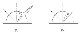
レンダリング画像において、光源の写り込みを判定する際には、投影面上の各画素位置における反射特性情報と、ずれ角ρと、を用いる。着目画素位置におけるずれ角ρが、着目画素位置の反射特性情報に基づいて決まる閾値mより大きい場合、着目画素位置における画素の鏡面反射成分を0とみなすことが出来る。ここで、この閾値mはBRDF特性に応じて決定され、鏡面反射成分が0になる最小のずれ角が閾値mとなる。図6にBRDF特性が異なる場合の閾値mの違いの例を示す。図6(a)は写像性の高いBRDF特性を示しており、図6(b)は写像性の低いBRDF特性を示している。
<Regarding Process Performed by Light Source Reflection Area Determination Unit 105 (Step S5)>
When determining the reflection of the light source in the rendered image, the reflection characteristic information at each pixel position on the projection plane and the shift angle ρ are used. When the shift angle ρ at the target pixel position is larger than the threshold value m determined based on the reflection characteristic information at the target pixel position, the specular reflection component of the pixel at the target pixel position can be regarded as zero. Here, the threshold value m is determined according to the BRDF characteristic, and the minimum deviation angle at which the specular reflection component becomes 0 is the threshold value m. FIG. 6 shows an example of the difference in the threshold value m when the BRDF characteristics are different. FIG. 6A shows a BRDF characteristic with high image clarity, and FIG. 6B shows a BRDF characteristic with low image clarity.
そして光源写り込み領域判定部105は、投影面上の各画素位置について鏡面反射成分が0と見なせるか否かを判定する。そして光源写り込み領域判定部105は、(鏡面反射成分が0と見なせない画素の数=閾値以下の角度を求めた画素の数)を計数する。そして光源写り込み領域判定部105は、この計数した画素数を、(投影面上の全画素数)で割った値を上記割合として求める。当然ながらこの割合は0〜1の間の値を取ることになる。
Then, the light source reflection
<順応白色点算出部106が行う処理(ステップS6)について>
本実施形態では、部分順応白色点の三刺激値を求める為に、仮想物体及び画像出力装置2の白色点の三刺激値と、基準となる白色点の三刺激値と、から、仮想物体及び画像出力装置2の部分順応白色点の三刺激値を求める計算式を、部分順応モデルとして用いる。この部分順応モデルについての詳細な説明は後述する。
<Regarding Processing (Step S6) Performed by Adaptation White
In this embodiment, in order to obtain the tristimulus value of the partially adapted white point, the virtual object and the tristimulus value of the white point of the virtual object and the
そして本実施形態では順応白色点算出部106は、画像出力装置2の白色点の三刺激値と、上記割合の値に応じて決まる仮想物体の白色点の三刺激値と、を上記部分順応モデルに与えてこの部分順応モデルを計算する。係る演算により、仮想物体の部分順応白色点の三刺激値と、画像出力装置2の部分順応白色点の三刺激値とを求める。
In this embodiment, the adaptive white
ここで、画像出力装置2の白色点の三刺激値は、メモリ3内に保持されている画像出力装置2のデバイスプロファイルに含まれている。また、基準となる白色点の三刺激値は、色温度が8500Kの黒体放射軌跡上の点を用い、これもまたメモリ3内に情報として格納されている。なお、等エネルギー白色等、他の白色点の三刺激値を、基準となる白色点の三刺激値として用いてもよい。
Here, the tristimulus value of the white point of the
ここで上記の通り、順応白色点算出部106は、部分順応モデルに与える仮想物体の白色点の三刺激値を、光源写り込み領域判定部105が求めた割合に応じて決めるのであるが、以下に、係る決定の方法について説明する。
Here, as described above, the adaptation white
順応白色点算出部106は、上記割合が0の場合(若しくは充分に0に近い場合)、完全拡散反射面に光源の分光放射輝度値φ(λ)を掛け合わせて算出した三刺激値を、仮想物体の白色点の三刺激値として部分順応モデルに与える。なお、上記割合が0の場合に部分順応モデルに与える三刺激値についてはこれ以外にも考えられ、例えば、投影面上の各画素位置における拡散反射成分を参照し、最も輝度の高い画素位置における三刺激値を、仮想物体の白色点の三刺激値としても良い。
The adaptive white
順応白色点算出部106は、上記割合が1の場合(若しくは充分に1に近い場合)、レンダリング画像内で最も強度が高い鏡面反射成分の輝度値Yを仮想物体の白色点の輝度値とする。なお、仮想物体の白色点の色度は、完全拡散反射面の三刺激値の色度と同じ色度とする。
When the ratio is 1 (or sufficiently close to 1), the adaptive white
順応白色点算出部106は、上記割合が0〜1の場合、上記割合が0の場合に部分順応モデルに与えるものとして説明した三刺激値と、上記割合が1の場合に部分順応モデルに与えるものとして説明した三刺激値と、を上記割合の値に応じて合成する。例えば、上記割合がr(0<r<1)であるとする。この場合、上記割合が0の場合に部分順応モデルに与えるものとして説明した三刺激値に(1−r)を乗じた三刺激値と、上記割合が1の場合に部分順応モデルに与えるものとして説明した三刺激値にrを乗じた三刺激値と、を加算した結果を求める。そして順応白色点算出部106は、この加算結果(合成結果)を、仮想物体の白色点の三刺激値として部分順応モデルに与える。
The adaptation white
これにより、順応白色点算出部106は、画像出力装置2の白色点、光源の分光放射輝度、仮想物体のBRDF特性、を考慮して、仮想物体の部分順応白色点の三刺激値と、画像出力装置2の部分順応白色点の三刺激値と、を求めることができる。
Accordingly, the adaptive white
<色変換部107が行う処理(ステップS8)について>
先ず色変換部107は、メモリ3に格納されている画像出力装置2のデバイスプロファイル内に記述されている各格子点の三刺激値XYZを読み出す。図7に画像出力装置2のデバイスプロファイルの一例を示す。図7に示す如く、デバイスプロファイルには、RGB色空間中における各格子点に対応する三刺激値XYZが記述されている。
<Regarding Process Performed by Color Conversion Unit 107 (Step S8)>
First, the
そして色変換部107は、ステップS6で求めた「画像出力装置2の部分順応白色点の三刺激値」を用いて、デバイスプロファイルから読み出した各格子点の三刺激値XYZに対してCIECAM02色順応変換を行う。これにより、各格子点の三刺激値XYZをJCh値に変換する。そして色変換部107は、各格子点のJch値を参照して、最外郭の格子点を特定し、画像出力装置2の色再現範囲を求める。
Then, the
次に色変換部107は、ステップS6で求めた「仮想物体の部分順応白色点の三刺激値」を用いて、投影面上の各画素位置について得た三刺激値XYZに対してCIECAM02色順応変換を行う。これにより、投影面上の各画素位置について得た三刺激値XYZをJch値に変換する。なお、本実施形態では色順応変換にCIECAM02を用いているが、VonKriesの色順応式等、他の色順応変換を用いても良い。
Next, the
次に色変換部107は、投影面上の各画素位置について求めたJch値を、上記色再現範囲内に色圧縮(カラリメトリック色域圧縮)を行う。色域圧縮処理は、色再現範囲外の色を色再現範囲内の色に変換するために行う。カラリメトリック色域圧縮では、色再現範囲内の色はそのまま保ち、色再現範囲外の色は色再現範囲の最も近い点に圧縮する手法である。なお、色圧縮には様々なものがあり、カラリメトリック以外の色圧縮を用いても良い。
Next, the
そして色変換部107は、ステップS6で求めた「仮想物体の部分順応白色点の三刺激値」を用いて、色圧縮済みのJch値に対してCIECAM02色順応逆変換を行う。これにより、投影面上の各画素位置についてJch値から三刺激値XYZに変換することができる。次に色変換部107は、画像出力装置2のデバイスプロファイルに記述されている、「三刺激値XYZとRGB値との対応情報」を用いて、この三刺激値XYZをRGB値に変換する。これにより、投影面上の各画素位置について三刺激値XYZをRGB値に変換することができる。デバイスプロファイルにない三刺激値XYZをRGB値に変換する場合には、この三刺激値XYZの周囲の格子点の三刺激値XYZから、四面体補間等の補間処理を用いてRGB値を求める。
Then, the
以上の処理により、投影面上の各画素位置に対するRGB値を確定させることができるので、投影面上に、RGB値を有する画素で構成されているレンダリング画像を形成することができる。 With the above processing, the RGB value for each pixel position on the projection plane can be determined, so that a rendered image composed of pixels having RGB values can be formed on the projection plane.
<順応モデルについて>
図10は、白色点の関係を概念的に示す図である。人間の視覚系はモニタの観察時も、仮想物体の観察時も光源の色を完全に補正することはできない。それ故、不完全順応を補正する必要がある。不完全順応を正確に補正するには、人間の視覚系が最も白いと感じる白色を(図10に△印で示す)基準白色として用いるべきである。そこで、上記の通り、色温度8500Kの黒体放射軌跡上の点を基準としての白色点として用いる。これは、モニタに白色を表示して白色の色温度を変化させた場合に被験者が最も好ましいと感じた白色の実験結果に基づく。勿論、基準白色は、この白色点に限られるわけではなく、異なる白色点、例えば等エネルギ白色よりも高い色温度をもつ、昼光軌跡上の白色点を設定してもよい。
<Adaptation model>
FIG. 10 is a diagram conceptually showing the relationship between white points. The human visual system cannot completely correct the color of the light source when observing a monitor or a virtual object. Therefore, it is necessary to correct incomplete adaptation. In order to accurately correct incomplete adaptation, the white color that the human visual system feels the most white should be used as the reference white color (indicated by a Δ mark in FIG. 10). Therefore, as described above, a point on the black body radiation locus with a color temperature of 8500K is used as a white point. This is based on a white experiment result that the subject felt most preferable when white color was displayed on the monitor and the white color temperature was changed. Of course, the reference white is not limited to this white point, and a different white point, for example, a white point on a daylight locus having a color temperature higher than that of an equal energy white may be set.
順応モデルを用いた計算では、画像出力装置2の白色点(以下、モニタ白色点)の色度uWm, vWmと、仮想物体の白色点(以下、仮想物体白色点)の色度uWp, vWpを以下の式(1)によって計算する。
In the calculation using the adaptation model, the chromaticity u Wm , v Wm of the white point (hereinafter referred to as monitor white point) of the
uWi = 4・XWi/(XWi + 15・YWi + 3・ZWi)
vWi = 6・YWi/(XWi + 15・YWi + 3・ZWi) …(1)
ここで、i = m, p
XWmYWmZWmはモニタ白色点の三刺激値
XWpYWpZWpは仮想物体白色点の三刺激値
次に、モニタ白色点の色度に対応するモニタ白色点の色温度TWmと、仮想物体白色点の色度に対応する仮想物体白色点の色温度TWpを、例えば、メモリ3が記憶する色度-色温度テーブルから取得する。
u Wi = 4 ・ X Wi / (X Wi + 15 ・ Y Wi + 3 ・ Z Wi )
v Wi = 6 · Y Wi / (X Wi + 15 · Y Wi + 3 · Z Wi )… (1)
Where i = m, p
X Wm Y Wm Z Wm is the tristimulus value of the monitor white point
X Wp Y Wp Z Wp is the tristimulus value of the virtual object white point.Next , the color temperature T Wm of the monitor white point corresponding to the chromaticity of the monitor white point and the virtual object white corresponding to the chromaticity of the virtual object white point The point color temperature T Wp is acquired from, for example, a chromaticity-color temperature table stored in the
次に、不完全順応補正用の、モニタ白色点の色温度T'Wmと、仮想物体白色点の色温度T'Wpを、以下の式(2)によって算出する。なお、基準白色点の色温度TWrは、上述したように8500Kである。 Next, the color temperature T ′ Wm of the monitor white point and the color temperature T ′ Wp of the virtual object white point for incomplete adaptation correction are calculated by the following equation (2). Note that the color temperature T Wr of the reference white point is 8500K as described above.
1/T'Wm = {kinc_m・1/TWm} + {(1 - kinc_m)・1/TWr}
1/T'Wp = {kinc_p・1/TWp} + {(1 - kinc_p)・1/TWr} …(2)
ここで、kinc_iは不完全順応係数
0 ≦ kinc_i ≦1
なお、不完全順応係数は、ユーザが設定した値を利用するが、関数などを利用して自動的に算出することもできる。また、上記の計算に色温度の逆数を用いるのは、色温度の差は人間の知覚する色差に対応しないが、色温度の逆数は人間の知覚に対してほぼ均等になるからである。
1 / T ' Wm = {k inc_m · 1 / T Wm } + {(1-k inc_m ) · 1 / T Wr }
1 / T ' Wp = {k inc_p · 1 / T Wp } + {(1-k inc_p ) · 1 / T Wr }… (2)
Where k inc_i is the incomplete adaptation coefficient
0 ≤ k inc_i ≤ 1
The incomplete adaptation coefficient uses a value set by the user, but can be automatically calculated using a function or the like. The reason why the reciprocal of the color temperature is used in the above calculation is that the difference in color temperature does not correspond to the color difference perceived by humans, but the reciprocal of the color temperature is almost equal to human perceptions.
式(2)よって求めた色温度の白色点を利用すれば、不完全順応を正確に補正し、画像出力装置2や仮想物体を単独に観察する場合の色の見えを正確に予測することができる。ただし、画像出力装置2と仮想物体を同時に観察する場合は、単独に観察する場合と順応状態が異なり、画像出力装置2を観察する場合は仮想物体白色点の影響を、仮想物体を観察する場合はモニタ白色点の影響を受けると考えられる。
By using the white point of the color temperature obtained by equation (2), it is possible to accurately correct imperfect adaptation and accurately predict the color appearance when observing the
そこで、部分順応を考慮して部分順応補正用の、モニタ白色点の色温度T”Wmと、仮想物体白色点の色温度T”Wpを、以下の式(3)によって計算する。 Therefore, considering the partial adaptation, the color temperature T ″ Wm of the monitor white point and the color temperature T ″ Wp of the virtual object white point for partial adaptation correction are calculated by the following equation (3).
1/T”Wm = (Km・L*m・1/T'Wm - Km'・L*p・1/T'Wp)/(Km・L*m + Km'・L*p)
1/T”Wp = (Kp・L*p・1/T'Wp - Kp'・L*m・1/T'Wm)/(Kp・L*p + Kp'・L*m) …(3)
ここで、Ki = kmix_iは部分順応係数
Ki' = 1 - Ki
0 ≦ Ki ≦ 1
L*iは白色点の輝度による重み係数
なお、部分順応係数は、ユーザが設定した値を利用するが、関数などを利用して自動的に算出することもできる。また、重み係数L*iは、白色点の輝度が高い方に、より順応するという考えから式(4)によって算出する。
1 / T ” Wm = (Km ・ L * m・ 1 / T'Wm -Km '・ L * p・ 1 / T'Wp ) / (Km ・ L * m + Km' ・ L * p )
1 / T ” Wp = (Kp · L * p · 1 / T'Wp -Kp '· L * m · 1 / T'Wm ) / (Kp · L * p + Kp' · L * m )… (3 )
Where Ki = k mix_i is the partial adaptation coefficient
Ki '= 1-Ki
0 ≤ Ki ≤ 1
L * i is a weighting coefficient based on the brightness of the white point. The partial adaptation coefficient uses a value set by the user, but can also be automatically calculated using a function or the like. Further, the weighting factor L * i is calculated by the equation (4) based on the idea that the white point is more adapted to the higher luminance of the white point.
YWm ≦ YWp の場合 L*m = 116.0×(YWm/YWp)1/3 - 16.0
else L*m = 100
YWp ≦ YWm の場合 L*m = 116.0×(YWp/YWm)1/3 - 16.0 …(4)
else L*p = 100
次に、前述した色度-色温度テーブルよって、部分順応補正用のモニタ白色点の色温度に対応する色度u”Wm, v”Wmと、部分順応補正用の仮想物体白色点の色温度に対応する色度u”Wp, v”Wpを逆算する。そして、部分順応補正用のモニタ白色点の三刺激値X”WmY”WmZ”Wmを、以下の式(5)によって算出する。
When Y Wm ≤ Y Wp L * m = 116.0 × (Y Wm / Y Wp ) 1 / 3-16.0
else L * m = 100
When Y Wp ≤ Y Wm L * m = 116.0 × (Y Wp / Y Wm ) 1 /3-16.0… (4)
else L * p = 100
Next, according to the chromaticity-color temperature table described above, chromaticity u ” Wm , v” Wm corresponding to the color temperature of the monitor white point for partial adaptation correction, and the color temperature of the virtual object white point for partial adaptation correction The chromaticity u ” Wp , v” Wp corresponding to is calculated backward. Then, the tristimulus value X ″ Wm Y ″ Wm Z ″ Wm of the monitor white point for partial adaptation correction is calculated by the following equation (5).
YWm ≦ YWp の場合 Y”Wm = {(L*”Wm + 16.0)/116.0}3・YWp
else Y”Wm = YWm
X”Wm = (3.0/2.0)・(u”Wm/v”Wm)・Y”Wm …(5)
Z”Wm = (4.0・X”Wm/u”Wm - X”Wm - 15.0・Y”Wm)/3.0
ここで、L*”Wm = L*m・km + 100.0(1-km)
また、部分順応補正用の仮想物体白色点の三刺激値X”WpY”WpZ”Wpを式(6)によって算出する。
When Y Wm ≤ Y Wp Y ” Wm = {(L *” Wm + 16.0) /116.0} 3・ Y Wp
else Y ” Wm = Y Wm
X ” Wm = (3.0 / 2.0) ・ (u” Wm / v ” Wm ) ・ Y” Wm … (5)
Z ” Wm = (4.0 · X” Wm / u ” Wm -X” Wm -15.0 · Y ” Wm ) /3.0
Where L * ” Wm = L * m · k m + 100.0 (1-k m )
Further, the tristimulus value X ″ Wp Y ″ Wp Z ″ Wp of the virtual object white point for partial adaptation correction is calculated by Equation (6).
YWp ≦ YWm の場合 Y”Wp = {(L*”Wp + 16.0)/116.0}3・YWm
else Y”Wp = YWp
X”Wp = (3.0/2.0)・(u”Wp/v”Wp)・Y”Wp …(6)
Z”Wp = (4.0・X”Wp/u”Wp - X”Wp - 15.0・Y”Wp)/3.0
ここで、L*”Wp = L*p・kp + 100.0(1-kp)
以上の説明により、本実施形態によれば、光源の写り込み領域の面積に応じた最適な順応白色点を用いて色変換を行なうことで、実際の物体の見えをより忠実に再現することができる。
When Y Wp ≤ Y Wm Y ” Wp = {(L *” Wp + 16.0) /116.0} 3・ Y Wm
else Y ” Wp = Y Wp
X ” Wp = (3.0 / 2.0) ・ (u” Wp / v ” Wp ) ・ Y” Wp … (6)
Z ” Wp = (4.0 · X” Wp / u ” Wp -X” Wp -15.0 · Y ” Wp ) /3.0
Where L * ” Wp = L * p * k p + 100.0 (1-k p )
As described above, according to the present embodiment, it is possible to more faithfully reproduce the appearance of an actual object by performing color conversion using the optimal adaptation white point according to the area of the reflection area of the light source. it can.
[第2の実施形態]
第1の実施形態では、(投影面上の総画素数)に対する(鏡面反射成分が0と見なせない画素の数)の割合、即ち、光源写り込み領域の面積に応じて順応白色点を算出した。本実施形態では、レンダリング画像上の各画素位置について、光源の中心点の写り込みからの距離に応じて順応白色点を算出する。
[Second Embodiment]
In the first embodiment, the adaptive white point is calculated according to the ratio of (the number of pixels whose specular reflection component cannot be regarded as 0) to (the total number of pixels on the projection plane), that is, the area of the light source reflection region. did. In the present embodiment, an adaptive white point is calculated for each pixel position on the rendered image according to the distance from the reflection of the center point of the light source.
先ず、本実施形態に係る画像処理装置83の機能構成例とその周辺機器について、図8を用いて説明する。図8において図1と同じ部分については同じ参照番号を付しており、その説明は省略する。 First, a functional configuration example of the image processing apparatus 83 according to the present embodiment and its peripheral devices will be described with reference to FIG. 8, the same parts as those in FIG. 1 are denoted by the same reference numerals, and the description thereof is omitted.
光源中心写り込み位置判定部815は、投影面上のレンダリング画像を形成する為の領域(レンダリング画像領域)内の各画素位置について、光源の中心点の写り込み位置からの距離を判定する。順応白色点算出部816は、光源中心写り込み位置判定部815による判定結果に応じて、レンダリング画像領域内の各画素に対する順応白色点を算出する。
The light source center reflection
次に、画像処理装置83が1フレーム分のレンダリング画像を生成するために行う処理について、同処理のフローチャートを示す図9を用いて説明する。然るに、複数フレーム分のレンダリング画像を画像出力装置2に出力する場合は、図8のフローチャートに従った処理を、それぞれのフレームについて行うことになる。
Next, processing performed by the image processing apparatus 83 to generate a rendering image for one frame will be described with reference to FIG. 9 showing a flowchart of the processing. However, when rendering images for a plurality of frames are output to the
ステップS901〜ステップS904の各ステップにおける処理はそれぞれ、上記のステップS1〜ステップS4の各ステップにおける処理と同様であるため、その説明は省略する。なお、ステップS901〜ステップS904はステップS1〜ステップS4と同様であるものの、以下の処理において不要となる情報を求める処理は省略することができる。 Since the processes in steps S901 to S904 are the same as the processes in steps S1 to S4, the description thereof is omitted. Although steps S901 to S904 are the same as steps S1 to S4, the processing for obtaining unnecessary information in the following processing can be omitted.
ステップS905では、光源中心写り込み位置判定部815は、レンダリング画像領域内の画素群から、未だ選択していない画素を1つ選択する。そしてステップS906では、光源中心写り込み位置判定部815は、投影面上の光源の中心点の写り込み位置を求め、求めた位置からステップS905で選択した画素(選択画素)の位置(選択画素位置)までの距離を求める。本ステップにおける処理の詳細については後述する。
In step S905, the light source center reflection
次に、ステップS907では順応白色点算出部816は、次の処理を行う。選択画素についてステップS906で求めた距離に基づいて、画像出力装置2の白色点の三刺激値、仮想物体の白色点の三刺激値、基準としての白色点の三刺激値を用いて、画像出力装置2の順応白色点の三刺激値、選択画素の順応白色点の三刺激値を求める。
Next, in step S907, the adaptive white
ステップS908では色変換部107は、順応白色点算出部816が求めた順応白色点を用いて、選択画素のRGB値を確定させる。ステップS908における処理は、画素単位で色変換処理を行う点を除けば、上記のステップS8と同じ処理である。
In step S <b> 908, the
ステップS905でレンダリング画像領域内の全ての画素を選択したのであれば処理はステップS909を介してステップS910に進み、ステップS905で未だ選択していない画素があれば、処理はステップS909を介してステップS905に戻る。ステップS910では、画像出力部108は、色変換部107により全ての画素のRGB値が確定したレンダリング画像を、画像出力装置2に対して出力する。
If all the pixels in the rendering image area have been selected in step S905, the process proceeds to step S910 via step S909. If there is a pixel that has not been selected in step S905, the process proceeds to step S909. The process returns to S905. In step S <b> 910, the
<光源中心写り込み位置判定部815が行う処理(ステップS906)について>
光源中心写り込み位置判定部815は投影面上の各画素位置のうち光源の中心点からの光線の方向ベクトルLに対する鏡面反射光の方向ベクトルSと視点52からの直線Vの方向が平行(ずれ角ρが最も0に近い)となる画素位置Cを特定する。即ちこの画素位置Cを「光源中心写り込み位置」として特定する。この画素位置Cの特定処理では、投影面のサイズはレンダリング画像のサイズよりも充分に大きく設けておく。
<Processing Performed by Light Source Center Reflection Position Determination Unit 815 (Step S906)>
The light source center reflection
次に光源中心写り込み位置判定部815は、画素位置Cと選択画素の位置との間の距離を求める。そして次に光源中心写り込み位置判定部815は、この求めた距離を分子、レンダリング画像領域の対角線距離を分母とする分数の値を計算する。なお、分母はこれに限定するものではない。
Next, the light source center reflection
そして光源中心写り込み位置判定部815は、求めた分数の値が1よりも大きい場合には判定結果として0を出力し、求めた分数の値が1の場合には判定結果として0を出力し、求めた分数の値が0の場合には判定結果として1を出力する。また、求めた分数の値がr(0<r<1)の場合には判定結果として(1−r)を出力する。
The light source center reflection
<順応白色点算出部816が行う処理(ステップS907)について>
第1の実施形態では、レンダリング画像に対して判定結果は一意に決まっていたため部分順応白色点は固定であった。本実施形態では、レンダリング画像の画素毎に判定結果が異なるため、部分順応白色点も画素毎に異なる。
<Regarding Processing (Step S907) Performed by Adaptation White
In the first embodiment, since the determination result is uniquely determined for the rendered image, the partially adapted white point is fixed. In this embodiment, since the determination result is different for each pixel of the rendered image, the partially adapted white point is also different for each pixel.
部分順応モデルに入力する仮想物体の白色点の三刺激値は以下のようにして決める。先ず、光源中心写り込み位置判定部815による判定結果が1の場合、画素位置Cにおける鏡面反射光Sの輝度値Yを仮想物体の白色点の輝度値とする。また、仮想物体の白色点の色度は、完全拡散反射面の三刺激値の色度と同じ色度とする。
The tristimulus value of the white point of the virtual object input to the partial adaptation model is determined as follows. First, when the determination result by the light source center reflection
光源中心写り込み位置判定部815による判定結果が0の場合、完全拡散反射面に光源の分光放射輝度φ(λ)を掛け合わせて算出した三刺激値を、選択画素の白色点の三刺激値として部分順応モデルに与える。
When the determination result by the light source center reflection
光源中心写り込み位置判定部815による判定結果が0〜1の場合、第1の実施形態と同様、上記判定結果が0の場合の三刺激値と、上記判定結果が1の場合の三刺激値と、を上記判定結果の値に応じて合成する。例えば、上記判定結果がf(0<f<1)であるとする。この場合、上記判定結果が0の場合の三刺激値に(1−f)を乗じた三刺激値と、上記判定結果が1の場合の三刺激値にfを乗じた三刺激値と、を加算した結果を求める。そして順応白色点算出部816は、この加算結果(合成結果)を、選択画素の白色点の三刺激値として部分順応モデルに与える。
When the determination result by the light source center reflection
以上の説明により、本実施形態によれば、光源中心の写り込み位置からの距離に応じた最適な順応白色点を用いて色変換を行なうことで、実際の物体の見えをより忠実に再現することが可能となる。 As described above, according to the present embodiment, the appearance of an actual object is more faithfully reproduced by performing color conversion using the optimal adaptation white point corresponding to the distance from the reflection position at the center of the light source. It becomes possible.
[第3の実施形態]
第1の実施形態では図1に示した画像処理装置1を構成する各部は何れもハードウェアで構成されているものとして説明したし、第2の実施形態では図8に示した画像処理装置83を構成する各部は何れもハードウェアで構成されているものとして説明した。しかし、これら各部の一部若しくは全部をソフトウェア(コンピュータプログラム)で構成しても良い。
[Third Embodiment]
In the first embodiment, each part constituting the
図1,8に示した画像処理装置1(83)を構成する各部をソフトウェアで構成する場合、このソフトウェアは、CPU等の実行部、RAM、ROM、ハードディスク等のメモリを有するコンピュータにより実行されることになる。この場合、このソフトウェアは、このメモリに格納され、この実行部により実行されることになる。もちろん、このソフトウェアを実行するコンピュータの構成については特に限定するものではない。 When the units constituting the image processing apparatus 1 (83) shown in FIGS. 1 and 8 are configured by software, the software is executed by a computer having an execution unit such as a CPU and a memory such as a RAM, a ROM, and a hard disk. It will be. In this case, the software is stored in the memory and executed by the execution unit. Of course, the configuration of the computer that executes the software is not particularly limited.
[その他の実施形態]
また、本発明は、以下の処理を実行することによっても実現される。即ち、上述した実施形態の機能を実現するソフトウェア(プログラム)を、ネットワーク又は各種記憶媒体を介してシステム或いは装置に供給し、そのシステム或いは装置のコンピュータ(またはCPUやMPU等)がプログラムを読み出して実行する処理である。
[Other Embodiments]
The present invention can also be realized by executing the following processing. That is, software (program) that realizes the functions of the above-described embodiments is supplied to a system or apparatus via a network or various storage media, and a computer (or CPU, MPU, etc.) of the system or apparatus reads the program. It is a process to be executed.
Claims (5)
仮想空間中に配されている物体の情報、及び光源の情報を取得する第一取得手段と、
前記物体を観察するための観察条件を取得する第二取得手段と、
前記観察条件に基づいて前記物体を観察した際の、前記物体における前記光源の写り込みの状態を決定する第一決定手段と、
前記写り込みの状態に基づいて、前記物体を画像出力部により表示する際の順応白色点を決定する第二決定手段と
を備えることを特徴とする画像処理装置。 An image processing apparatus,
First acquisition means for acquiring information on an object arranged in a virtual space and information on a light source;
Second acquisition means for acquiring an observation condition for observing the object;
First determining means for determining a reflection state of the light source in the object when the object is observed based on the observation condition;
An image processing apparatus comprising: a second determination unit configured to determine an adaptive white point when the object is displayed by the image output unit based on the reflection state .
前記仮想空間中に配されている投影面において前記物体のレンダリング画像を形成するための領域をレンダリング画像領域とし、該レンダリング画像領域内の着目画素位置と、前記仮想空間中に設定されている視点の位置と、を通る直線を求め、該求めた直線と前記物体との交点位置を求める第1の計算手段と、
前記光源から照射され、前記交点位置で反射する反射光の方向ベクトルと、前記直線の方向ベクトルと、が為す角度を求める第2の計算手段と、
前記反射光の輝度スペクトルを求め、該求めた輝度スペクトルから三刺激値を計算する第3の計算手段と、
前記第1乃至3の計算手段による計算処理を、前記レンダリング画像領域内の各画素位置について行うことで、前記レンダリング画像領域内の各画素位置について前記角度と前記三刺激値とを求める手段と、
前記角度が0に最も近い画素位置を特定し、該特定した画素位置と、前記レンダリング画像領域内の各画素位置との距離を求め、前記レンダリング画像領域の対角線距離に対する該求めた距離の比を求める手段と
を備えることを特徴とする請求項1に記載の画像処理装置。 The first determining means includes
An area for forming a rendering image of the object on the projection plane arranged in the virtual space is defined as a rendering image area, and a target pixel position in the rendering image area and a viewpoint set in the virtual space A first calculation means for obtaining a straight line passing through the position, and obtaining an intersection position between the obtained straight line and the object;
Second calculation means for obtaining an angle formed by a direction vector of reflected light emitted from the light source and reflected at the intersection position and a direction vector of the straight line;
Obtaining a luminance spectrum of the reflected light and calculating a tristimulus value from the obtained luminance spectrum;
The calculation process by the first to third calculation means, by performing for each pixel position of the rendering image area, means for determining said tristimulus value and the angle for each pixel position of the rendering image area,
It said angle identifying the closest pixel position to 0, and a pixel position the identified seek distance between each pixel position of the rendering image area, the ratio of the distances determined the relative diagonal length of the rendered image area Means to seek and
The image processing apparatus according to claim 1, further comprising:
前記レンダリング画像領域からの選択画素位置の白色点の三刺激値と、前記画像出力部の白色点の三刺激値と、基準となる白色点の三刺激値と、から、前記選択画素位置の部分順応白色点の三刺激値と、前記画像出力部の部分順応白色点の三刺激値と、を求める計算式に対して、前記画像出力部のデバイスプロファイルに含まれている前記画像出力部の白色点の三刺激値と、前記比の値に応じて決まる前記選択画素位置の白色点の三刺激値と、を与えて前記計算式を計算することで、前記選択画素位置の部分順応白色点の三刺激値と、前記画像出力部の部分順応白色点の三刺激値とを求める処理を行い、
前記比が0の場合には、完全拡散反射面の三刺激値に前記光源の分光放射輝度値を乗ずることで算出した三刺激値を、前記選択画素位置の白色点の三刺激値として前記計算式に与え、
前記比が1の場合には、前記選択画素位置における鏡面反射成分の輝度値と、完全拡散反射面の三刺激値の色度と同じ色度と、から成る三刺激値を、前記選択画素位置の白色点の三刺激値として前記計算式に与え、
前記比が0〜1の間の値である場合には、前記比が0の場合の三刺激値と、前記比が1の場合の三刺激値と、を該比に応じて合成した三刺激値を、前記選択画素位置の白色点の三刺激値として前記計算式に与える
ことを特徴とする請求項2に記載の画像処理装置。 The second determining means includes
The portion of the selected pixel position from the tristimulus value of the white point at the selected pixel position from the rendered image region, the tristimulus value of the white point of the image output unit , and the tristimulus value of the white point as a reference tristimulus values of the adaptive white point, the tristimulus values of the image output unit partial adaptation white point of the relative formulas for obtaining the white of the image output unit included in the device profile of the image output unit The tristimulus value of the point and the tristimulus value of the white point at the selected pixel position determined according to the ratio value are calculated to calculate the calculation formula, thereby calculating the partial adaptive white point of the selected pixel position. Processing to determine tristimulus values and tristimulus values of the partially adapted white point of the image output unit ,
When the ratio is 0, the tristimulus value calculated by multiplying the tristimulus value of the perfect diffuse reflection surface by the spectral radiance value of the light source is used as the tristimulus value of the white point at the selected pixel position. Given in the formula,
If the ratio is 1, the luminance value of the specular reflection component in the selected pixel location, the chromaticity of the tristimulus values of a perfect reflecting diffuser and the same chromaticity, the tristimulus values consisting of the selected pixel position Is given to the above formula as the tristimulus value of the white point of
When the ratio is a value between 0 and 1, the tristimulus value obtained by combining the tristimulus value when the ratio is 0 and the tristimulus value when the ratio is 1 according to the ratio The image processing apparatus according to claim 2, wherein a value is given to the calculation formula as a tristimulus value of a white point at the selected pixel position.
前記画像処理装置の第一取得手段が、仮想空間中に配されている物体の情報、及び光源の情報を取得する工程と、
前記画像処理装置の第二取得手段が、前記物体を観察するための観察条件を取得する工程と、
前記画像処理装置の第一決定手段が、前記観察条件に基づいて前記物体を観察した際の、前記物体における前記光源の写り込みの状態を決定する工程と、
前記画像処理装置の第二決定手段が、前記写り込みの状態に基づいて、前記物体を画像出力部により表示する際の順応白色点を決定する工程と
を備えることを特徴とする画像処理方法。 An image processing method performed by an image processing apparatus,
A first acquisition unit of the image processing apparatus acquires information on an object arranged in a virtual space and information on a light source;
A second acquisition unit of the image processing apparatus acquires an observation condition for observing the object;
A step of determining a reflection state of the light source in the object when the first determining means of the image processing apparatus observes the object based on the observation condition;
A second determining unit of the image processing apparatus, further comprising: determining an adaptive white point when the object is displayed by the image output unit based on the reflection state .
Priority Applications (3)
| Application Number | Priority Date | Filing Date | Title |
|---|---|---|---|
| JP2010118769A JP5615041B2 (en) | 2010-05-24 | 2010-05-24 | Image processing apparatus and image processing method |
| US13/582,099 US20120327086A1 (en) | 2010-05-24 | 2011-04-27 | Image processing apparatus and image processing method |
| PCT/JP2011/060691 WO2011148776A1 (en) | 2010-05-24 | 2011-04-27 | Image processing apparatus and image processing method |
Applications Claiming Priority (1)
| Application Number | Priority Date | Filing Date | Title |
|---|---|---|---|
| JP2010118769A JP5615041B2 (en) | 2010-05-24 | 2010-05-24 | Image processing apparatus and image processing method |
Publications (3)
| Publication Number | Publication Date |
|---|---|
| JP2011248476A JP2011248476A (en) | 2011-12-08 |
| JP2011248476A5 JP2011248476A5 (en) | 2013-05-16 |
| JP5615041B2 true JP5615041B2 (en) | 2014-10-29 |
Family
ID=45003768
Family Applications (1)
| Application Number | Title | Priority Date | Filing Date |
|---|---|---|---|
| JP2010118769A Expired - Fee Related JP5615041B2 (en) | 2010-05-24 | 2010-05-24 | Image processing apparatus and image processing method |
Country Status (3)
| Country | Link |
|---|---|
| US (1) | US20120327086A1 (en) |
| JP (1) | JP5615041B2 (en) |
| WO (1) | WO2011148776A1 (en) |
Families Citing this family (9)
| Publication number | Priority date | Publication date | Assignee | Title |
|---|---|---|---|---|
| JP6100086B2 (en) * | 2013-05-15 | 2017-03-22 | キヤノン株式会社 | Image processing apparatus and image processing method |
| JP6506507B2 (en) * | 2013-05-15 | 2019-04-24 | キヤノン株式会社 | Measurement apparatus and control method thereof |
| US9489918B2 (en) * | 2013-06-19 | 2016-11-08 | Lenovo (Beijing) Limited | Information processing methods and electronic devices for adjusting display based on ambient light |
| CN105378573B (en) | 2013-07-19 | 2017-12-22 | 富士通株式会社 | The computational methods of information processor, examination scope |
| US9266287B2 (en) | 2013-09-18 | 2016-02-23 | Disney Enterprises, Inc. | 3D printing with custom surface reflectance |
| JP6604744B2 (en) * | 2015-05-03 | 2019-11-13 | キヤノン株式会社 | Image processing apparatus, image processing method, image forming system, and program |
| US10850495B2 (en) * | 2016-01-29 | 2020-12-01 | Massachusetts Institute Of Technology | Topology optimization with microstructures |
| GB2605171B (en) * | 2021-03-24 | 2023-05-24 | Sony Interactive Entertainment Inc | Image rendering method and apparatus |
| GB2605158B (en) | 2021-03-24 | 2023-05-17 | Sony Interactive Entertainment Inc | Image rendering method and apparatus |
Family Cites Families (6)
| Publication number | Priority date | Publication date | Assignee | Title |
|---|---|---|---|---|
| JP3761263B2 (en) * | 1996-11-15 | 2006-03-29 | 富士写真フイルム株式会社 | Computer graphics reproduction method |
| US6226006B1 (en) * | 1997-06-27 | 2001-05-01 | C-Light Partners, Inc. | Method and apparatus for providing shading in a graphic display system |
| JP2000113215A (en) * | 1998-10-08 | 2000-04-21 | Dainippon Screen Mfg Co Ltd | Image processor, and recording medium recorded with program for executing processing therefor |
| AU2006200969A1 (en) * | 2006-03-07 | 2007-09-27 | Canon Information Systems Research Australia Pty Ltd | Print representation |
| WO2008062874A1 (en) * | 2006-11-22 | 2008-05-29 | Nikon Corporation | Image processing method, image processing program, image processing device and camera |
| JP4850676B2 (en) * | 2006-12-07 | 2012-01-11 | キヤノン株式会社 | Image generating apparatus and image generating method |
-
2010
- 2010-05-24 JP JP2010118769A patent/JP5615041B2/en not_active Expired - Fee Related
-
2011
- 2011-04-27 US US13/582,099 patent/US20120327086A1/en not_active Abandoned
- 2011-04-27 WO PCT/JP2011/060691 patent/WO2011148776A1/en active Application Filing
Also Published As
| Publication number | Publication date |
|---|---|
| WO2011148776A1 (en) | 2011-12-01 |
| JP2011248476A (en) | 2011-12-08 |
| US20120327086A1 (en) | 2012-12-27 |
Similar Documents
| Publication | Publication Date | Title |
|---|---|---|
| JP5615041B2 (en) | Image processing apparatus and image processing method | |
| JP5235805B2 (en) | Color processing method, color processing apparatus, and program | |
| US8711171B2 (en) | Image processing apparatus, method, and storage medium for performing soft proof processing | |
| JP4231661B2 (en) | Color reproduction device | |
| JP5153566B2 (en) | Image processing system, image processing apparatus, and image processing method | |
| JP2006215756A (en) | Image processing apparatus, image processing method, and program for the same | |
| JP2015507413A (en) | Spectral synthesis for image capture device processing. | |
| Hincapié-Ramos et al. | SmartColor: Real-time color correction and contrast for optical see-through head-mounted displays | |
| Menk et al. | Visualisation techniques for using spatial augmented reality in the design process of a car | |
| JP2010114506A (en) | Texture information data acquiring device and display control system with the same | |
| JP6028527B2 (en) | Display processing apparatus, display processing method, and program | |
| US20110292070A1 (en) | Image processing apparatus and image processing method | |
| US20180108168A1 (en) | Surface material pattern finish simulation device and surface material pattern finish simulation method | |
| US9135746B2 (en) | Image processing apparatus and control method thereof | |
| JP6792335B2 (en) | Image processing equipment and its method | |
| JP5941041B2 (en) | A method for normalizing a value indicating an equivalent lightness of a given color and a value indicating a vividness, a tone type determining method, a Munsell value calculating method, an image forming method, and an interface screen display device | |
| Geisler-Moroder et al. | Color-rendering indices in global illumination methods | |
| JP7191208B2 (en) | Method for measuring personal color space and method for correcting digital image according to personal color space | |
| JP7421607B2 (en) | Image processing device and method | |
| Navvab et al. | Evaluation of historical museum interior lighting system using fully immersive virtual luminous environment | |
| KR101366163B1 (en) | Hybrid color conversion method and system to optimize the performancein diverse color perception environment | |
| JP2014146163A (en) | Image processing apparatus, image processing method, image display method, and program | |
| Navvab | Measureable Domain for Colour Differences within Virtual Environment | |
| JP4225414B2 (en) | Image color correction apparatus, method, program, and recording medium | |
| Neumann et al. | Gamut clipping and mapping based on the coloroid system |
Legal Events
| Date | Code | Title | Description |
|---|---|---|---|
| A521 | Request for written amendment filed |
Free format text: JAPANESE INTERMEDIATE CODE: A523 Effective date: 20130402 |
|
| A621 | Written request for application examination |
Free format text: JAPANESE INTERMEDIATE CODE: A621 Effective date: 20130402 |
|
| TRDD | Decision of grant or rejection written | ||
| A01 | Written decision to grant a patent or to grant a registration (utility model) |
Free format text: JAPANESE INTERMEDIATE CODE: A01 Effective date: 20140811 |
|
| A61 | First payment of annual fees (during grant procedure) |
Free format text: JAPANESE INTERMEDIATE CODE: A61 Effective date: 20140909 |
|
| LAPS | Cancellation because of no payment of annual fees |