JP5609112B2 - How to create 3D image data - Google Patents
How to create 3D image data Download PDFInfo
- Publication number
- JP5609112B2 JP5609112B2 JP2009529855A JP2009529855A JP5609112B2 JP 5609112 B2 JP5609112 B2 JP 5609112B2 JP 2009529855 A JP2009529855 A JP 2009529855A JP 2009529855 A JP2009529855 A JP 2009529855A JP 5609112 B2 JP5609112 B2 JP 5609112B2
- Authority
- JP
- Japan
- Prior art keywords
- image
- arm
- video
- patient
- target
- Prior art date
- Legal status (The legal status is an assumption and is not a legal conclusion. Google has not performed a legal analysis and makes no representation as to the accuracy of the status listed.)
- Expired - Fee Related
Links
- 238000000034 method Methods 0.000 claims description 42
- 238000012937 correction Methods 0.000 claims description 27
- 238000012545 processing Methods 0.000 claims description 22
- 238000003384 imaging method Methods 0.000 claims description 15
- 239000003550 marker Substances 0.000 claims description 13
- 230000000694 effects Effects 0.000 claims description 2
- 238000002591 computed tomography Methods 0.000 description 31
- 230000036544 posture Effects 0.000 description 31
- 230000006870 function Effects 0.000 description 15
- 238000004458 analytical method Methods 0.000 description 8
- 230000008859 change Effects 0.000 description 6
- 238000005259 measurement Methods 0.000 description 5
- 230000008569 process Effects 0.000 description 5
- 230000008901 benefit Effects 0.000 description 4
- 238000004364 calculation method Methods 0.000 description 4
- 230000009467 reduction Effects 0.000 description 4
- 230000002159 abnormal effect Effects 0.000 description 3
- 210000000988 bone and bone Anatomy 0.000 description 3
- 238000010586 diagram Methods 0.000 description 3
- 238000005516 engineering process Methods 0.000 description 3
- 239000000463 material Substances 0.000 description 3
- 235000013405 beer Nutrition 0.000 description 2
- 238000001514 detection method Methods 0.000 description 2
- 230000006872 improvement Effects 0.000 description 2
- 208000028752 abnormal posture Diseases 0.000 description 1
- 238000010521 absorption reaction Methods 0.000 description 1
- 238000013170 computed tomography imaging Methods 0.000 description 1
- 238000010276 construction Methods 0.000 description 1
- 230000007547 defect Effects 0.000 description 1
- 230000001419 dependent effect Effects 0.000 description 1
- 238000003745 diagnosis Methods 0.000 description 1
- 238000002594 fluoroscopy Methods 0.000 description 1
- 238000005286 illumination Methods 0.000 description 1
- 238000010191 image analysis Methods 0.000 description 1
- 238000003780 insertion Methods 0.000 description 1
- 230000037431 insertion Effects 0.000 description 1
- 230000002452 interceptive effect Effects 0.000 description 1
- 238000012986 modification Methods 0.000 description 1
- 230000004048 modification Effects 0.000 description 1
- 238000010606 normalization Methods 0.000 description 1
- 230000004044 response Effects 0.000 description 1
- 238000009420 retrofitting Methods 0.000 description 1
- 238000001356 surgical procedure Methods 0.000 description 1
Images


Classifications
-
- A—HUMAN NECESSITIES
- A61—MEDICAL OR VETERINARY SCIENCE; HYGIENE
- A61B—DIAGNOSIS; SURGERY; IDENTIFICATION
- A61B6/00—Apparatus or devices for radiation diagnosis; Apparatus or devices for radiation diagnosis combined with radiation therapy equipment
- A61B6/44—Constructional features of apparatus for radiation diagnosis
- A61B6/4405—Constructional features of apparatus for radiation diagnosis the apparatus being movable or portable, e.g. handheld or mounted on a trolley
-
- H—ELECTRICITY
- H05—ELECTRIC TECHNIQUES NOT OTHERWISE PROVIDED FOR
- H05G—X-RAY TECHNIQUE
- H05G1/00—X-ray apparatus involving X-ray tubes; Circuits therefor
- H05G1/02—Constructional details
-
- A—HUMAN NECESSITIES
- A61—MEDICAL OR VETERINARY SCIENCE; HYGIENE
- A61B—DIAGNOSIS; SURGERY; IDENTIFICATION
- A61B6/00—Apparatus or devices for radiation diagnosis; Apparatus or devices for radiation diagnosis combined with radiation therapy equipment
- A61B6/44—Constructional features of apparatus for radiation diagnosis
- A61B6/4429—Constructional features of apparatus for radiation diagnosis related to the mounting of source units and detector units
- A61B6/4435—Constructional features of apparatus for radiation diagnosis related to the mounting of source units and detector units the source unit and the detector unit being coupled by a rigid structure
- A61B6/4441—Constructional features of apparatus for radiation diagnosis related to the mounting of source units and detector units the source unit and the detector unit being coupled by a rigid structure the rigid structure being a C-arm or U-arm
-
- A—HUMAN NECESSITIES
- A61—MEDICAL OR VETERINARY SCIENCE; HYGIENE
- A61B—DIAGNOSIS; SURGERY; IDENTIFICATION
- A61B6/00—Apparatus or devices for radiation diagnosis; Apparatus or devices for radiation diagnosis combined with radiation therapy equipment
- A61B6/58—Testing, adjusting or calibrating thereof
- A61B6/582—Calibration
- A61B6/583—Calibration using calibration phantoms
Landscapes
- Health & Medical Sciences (AREA)
- Life Sciences & Earth Sciences (AREA)
- Medical Informatics (AREA)
- Engineering & Computer Science (AREA)
- Radiology & Medical Imaging (AREA)
- Biomedical Technology (AREA)
- Biophysics (AREA)
- Nuclear Medicine, Radiotherapy & Molecular Imaging (AREA)
- Optics & Photonics (AREA)
- Pathology (AREA)
- Physics & Mathematics (AREA)
- High Energy & Nuclear Physics (AREA)
- Heart & Thoracic Surgery (AREA)
- Molecular Biology (AREA)
- Surgery (AREA)
- Animal Behavior & Ethology (AREA)
- General Health & Medical Sciences (AREA)
- Public Health (AREA)
- Veterinary Medicine (AREA)
- Apparatus For Radiation Diagnosis (AREA)
Description
本発明は、CアームX線透視装置を用いて作成されるCT画像に関する。 The present invention relates to a CT image created using a C-arm fluoroscope.
コンピューター断層撮影(CT)は、一般に、専用のCT装置を用いて行われる。前記CT装置は、高価であり、医療環境において数が限られており、その寸法及び重量のために医療施設内の専用の場所にある。CT装置が手術室に配置され、手術中の画像化に使用できることは、非常に稀である。これに対して、Cアーム型のX線透視画像装置は、安価であり、病院及び診療所の双方にあり、一般に、前記X線透視画像装置を診察場所又は手術室内にいる患者の位置へ移動させることができる程度に十分な可動性を有する。多くの先行技術文献に、一般のCアーム装置により提供された二次元画像データを用いてCT形式の三次元画像情報を提供する装置が記載されている。このような装置は、専用のCT装置の費用の一部でCT形式の情報を提供することができる。前記装置の少なくとも1つは、市販されており、Cアームを制御下でゆっくり回転させ、X線透視画像を作成するために所定の位置で停止させるためにモーターを使用する。 Computed tomography (CT) is generally performed using a dedicated CT apparatus. The CT devices are expensive, have a limited number in the medical environment, and are in a dedicated location within the medical facility because of their size and weight. It is very rare that a CT device is placed in the operating room and can be used for imaging during surgery. On the other hand, C-arm type fluoroscopic imaging devices are inexpensive and are present in both hospitals and clinics. In general, the X-ray fluoroscopic imaging devices are moved to the location of a patient in an examination place or operating room. It has sufficient mobility to be able to be made. Many prior art documents describe devices that provide CT format three-dimensional image information using two-dimensional image data provided by a general C-arm device. Such a device can provide CT format information at part of the cost of a dedicated CT device. At least one of the devices is commercially available and uses a motor to slowly rotate the C-arm under control and stop in place to create a fluoroscopic image.
このような、Cアームを有するCT装置は、「X線撮影装置及びCアームを用いたコンピューター断層撮影方法」に関する特許文献1に記載されている。特許文献1には、前記CT装置の目的及び利点が記載されているが、詳細な構成が記載されていない。「3D再構成のためのCアームキャリブレーション方法」に関するN. Navabによる特許文献2、「改良されたX線画像装置及び方法」に関するJ.W. Eberhard他による特許文献3及び「様々なラインと組み合わされた短時間スキャンサークルのためのアルゴリズムを用いたCT画像再構成方法」に関するG. Lauritsch他による特許文献4に他の装置が記載されている。また、K. Wiesent他による特許文献5に、位置座標と、物体の焦点及び検出位置とを計算することなく、X線Cアーム画像装置にボクセル操作の逆投影を生じさせる装置及び方法が記載されている。K. Wiesent他による特許文献6に、走査時に画像化され、画像の形状を明らかにする特定の印をCT装置に使用する方法及び装置が記載されている。 Such a CT apparatus having a C-arm is described in Japanese Patent Application Laid-Open No. 2004-228561 concerning “Computer tomography using X-ray imaging apparatus and C-arm”. Patent Document 1 describes the purpose and advantage of the CT apparatus, but does not describe a detailed configuration. N. Navab's US Pat. No. 6,099,096 on “C-arm calibration method for 3D reconstruction”, JW Eberhard et al. On “An improved X-ray imaging apparatus and method” and “combined with various lines” Another apparatus is described in G. Lauritsch et al. In US Pat. In addition, in US Pat. No. 6,057,049 by K. Wiesent et al., An apparatus and method for causing voxel manipulation backprojection on an X-ray C-arm imaging device without calculating position coordinates, object focus and detection position is described. ing. U.S. Patent No. 6,057,049 by K. Wiesent et al. Describes a method and apparatus for using a particular mark in a CT apparatus that is imaged during scanning and reveals the shape of the image.
「X線透視画像装置を用いてコンピューター断層撮影画像を取得し、表示する方法及び装置」に関するV.T. Jensen他による特許文献7に、診察及び診療のためのCT形式の情報を提供するCアーム装置が記載されている。前記Cアーム装置は、X線源と、患者のX線透視画像を取得する検出器とを備えるCアームを有する。前記Cアームは、少なくとも第1画像及び第2画像が得られる画像取得経路を経て移動される。取得モジュールが、前記画像取得経路に沿った所望の位置において多数の二次元X線透視画像を取得し、画像処理プロセッサーが前記二次元X線透視画像に基づいて三次元のオブジェクトデータを構築する。患者情報が三次元の患者情報に基づいて表示される。位置追跡器が前記検出器、前記患者及び(含まれている場合)手術器具の位置を追跡する。位置情報は、照射時間を制御するため及び患者情報を有するディスプレーに手術器具のグラフィック情報を重ね合わせるために使用される。
この装置は、専用装置であり、一般のCアームX線透視画像装置にない多くの追加機器、特に、前記X線源、前記患者、前記検出器及び前記手術器具の位置を測定するために必要な前記位置追跡器を有する。CT装置より安価であるが、この装置は、新たな機器の費用又は操作に必要な追加機器の取付けによる既存のCアームX線透視装置の改修費用を伴う。 This device is a dedicated device and is needed to measure the position of many additional instruments not found in typical C-arm fluoroscopic imaging devices, especially the X-ray source, the patient, the detector and the surgical instrument. The position tracker. Although cheaper than CT equipment, this equipment involves the expense of new equipment or the cost of retrofitting existing C-arm fluoroscopy equipment by installing additional equipment required for operation.
このため、既存のCアームX線透視画像装置の構造に変更や追加を加えることなく、簡単なソフトウェア処理により、前記CアームX線透視画像装置の出力データからCT形式の情報を取得し、これにより従来の装置及び方法の欠点を克服する装置が必要である。 Therefore, CT format information is obtained from the output data of the C-arm X-ray fluoroscopic image device by simple software processing without changing or adding to the structure of the existing C-arm X-ray fluoroscopic image device. Thus, there is a need for an apparatus that overcomes the shortcomings of conventional apparatus and methods.
本明細書に記載した先行技術文献の開示は、参照することによりその全部が本明細書に組み込まれる。 The disclosures of the prior art documents described in this specification are incorporated herein by reference in their entirety.
本発明は、二次元画像を提供する既存のCアームX線透視画像装置からCT形式の三次元情報を作成する装置及び方法を提供する。これにより、広く使用されているCアーム装置をCT形式の情報の提供に適合させることができる。本発明は、既存のCアーム装置を用いて実施されることができるように、好ましくは、従来のCアーム装置に存在する特徴を新たな方法で利用し、前記Cアーム装置の構造への変更又は追加を伴わない。 The present invention provides an apparatus and method for creating CT-format three-dimensional information from an existing C-arm fluoroscopic image apparatus that provides a two-dimensional image. Thereby, the widely used C-arm device can be adapted to provide information in the CT format. As the present invention can be implemented using an existing C-arm device, it is preferable to utilize the features existing in the conventional C-arm device in a new way, and to change the structure of the C-arm device. Or without addition.
本発明に係る装置は、患者に対する固定位置に配置された三次元のターゲットを使用し、手動で又はモーターによりCアームが患者の周囲において動かされている間に前記患者の関心領域の一連のビデオ画像を取得する。前記ビデオ画像に又は前記ビデオ画像のフレームの少なくとも大部分に前記関心領域が現されている限り、前記Cアームの中心又は前記患者の相対位置について仮定しない。 The device according to the present invention uses a three-dimensional target placed in a fixed position relative to the patient and a series of videos of the patient's region of interest while the C-arm is being moved around the patient, either manually or by motor. Get an image. As long as the region of interest appears in the video image or at least in the most part of the frame of the video image, no assumptions are made about the center of the C-arm or the relative position of the patient.
各ビデオ画像は、前記ターゲットの画像パターンの解析により前記患者に対するCアームの姿勢を測定するために解析される。その後、前記患者の前記関心領域の画像化されたデータを提供するため、後述の基準に従って、画像が選択される。これに代え、好ましくは、前記ターゲットの画像パターンの解析により前記患者に対する前記Cアームの姿勢を測定するために前記ビデオ画像から多くのフレーム又はインターレースビデオの場合における多くのフィールドが選択され、解析される。これらの方法によれば、前記患者の前記関心領域の三次元画像データを再構成するために使用される、関連する位置データを有する一連の二次元画像データが得られる。 Each video image is analyzed to measure the C-arm posture relative to the patient by analyzing the image pattern of the target. Thereafter, an image is selected according to the criteria described below to provide imaged data of the region of interest of the patient. Alternatively, preferably many fields in the case of many frames or interlaced video are selected and analyzed from the video image in order to measure the posture of the C-arm with respect to the patient by analysis of the image pattern of the target. The According to these methods, a series of two-dimensional image data with associated position data is obtained that is used to reconstruct the three-dimensional image data of the region of interest of the patient.
前記装置は、好ましくは、1又は2以上の以下の特徴を利用する。
(a)Cアーム画像装置から得られたビデオデータは、データ処理ソフトウェアが三次元CT情報を作成するための一連の二次元X線画像を提供するために利用される。画像化されたデータのビデオ表示は、通常、従来のCアーム装置で使用できるが、その用途は、一般に、医者が、画像化された関心領域を動画観察できるようにすることに限定されている。従来のCアーム装置は、一般に、PAL及びNTSCのような標準形式を用いてアナログビデオ画像としてビデオ画像を出力する。本発明の好適な実施例によれば、全ての画像を取得するためにCアームを停止させる必要がないため、連続的なビデオ画像の使用は、データ取得処理を従来のCアーム画像装置より高速化することができる。連続的なビデオ画像の使用がモーションブラーを生じさせ、(アナログビデオが使用されたときのインターレースのような)他の結果を伴うことがあるので、オンザフライ方式による、このような連続画像の取得を可能にするため、ぶれ補正技術を有する画像処理アルゴリズムが使用される。ビデオデータの使用の他の長所は、再構成に使用可能な多くの画像を利用できることである。
(b)前記Cアームの動きは、好ましくは、内蔵式の動作手段により又は簡単な手動操作によりなされ、一定である必要はない。
(c)前記患者に対する前記Cアームの姿勢は、前記X線透視画像において見ることができる三次元配置のX線非透過性のマーカーを有する三次元のターゲットを用いて測定される。前記ターゲットの画像の少なくとも一部が前記X線透視画像に表示されるように前記ターゲットは前記患者の上に又は前記患者の近傍に配置される。前記患者に対する前記ターゲットの絶対位置が知られている必要はないが、前記ターゲットの位置が前記患者に対して変更されないように前記ターゲットは、前記患者又は該患者が固定された手術台やベッドに取り付けられなければならない。前記装置のソフトウェアが各フレームの画像化されたデータの中で前記患者の位置及び方向を測定できるように前記ターゲットの画像情報は、任意の時点における前記Cアームの角度及び移動位置を測定するために従来のアルゴリズムを用いて処理される。前記ターゲットは、前記Cアームの姿勢の評価の精度、速度及び安定性を向上させるため、好ましくは、動的モデルを用いて前記ビデオ画像に沿って追跡される。
(d)前記ターゲットの実際の画像がより早く得られ、前記Cアームの姿勢がより早く測定されることができるように前記動的モデルは、好ましくは、連続的なフレームの得られた画像データを比較するために使用され、連続的なフレームにおけるターゲットプレートの位置の予測を可能にする。また、前記画像データが改善されることができるように前記動的モデルは、不足した又は異常な細部について前記画像データに修正を加えることができる。さらに、前記動的モデルの使用は、前記Cアームの歪み補正機能をより効率的に発揮させることができる。歪み補正は、画像の歪みを補正するために行われるキャリブレーション処理である。これは、所定の位置を有するマーカーボールを備えるファントムをイメージインテンシファイアに付け、前記マーカーボールの画像の歪みを除去するように歪み補正を行うことにより、実現される。1つの最初の完全な計算と、歪み補正ファントム画像の変化に応じて更新される、連続的なフレームのためのパラメーターとに依存するため、前記動的モデルの使用は全てのフレームについての完全な歪み補正計算の実行を不要にする。また、前記動的モデルは、好ましくは、画像をその質に応じて選択するために使用され、質の悪い画像を拒絶し又は修正する。
(e)CT形式のデータを作成し、前記関心領域の三次元画像の構築を可能にするため、前記ソフトウェアにより取得された、一連のビデオフレームからの出力データは再構成エンジンにより処理される。
The apparatus preferably utilizes one or more of the following features.
(A) Video data obtained from a C-arm imaging device is used by data processing software to provide a series of two-dimensional X-ray images for creating three-dimensional CT information. Video display of imaged data can usually be used with conventional C-arm devices, but its use is generally limited to allowing a doctor to view a moving image of an imaged region of interest. . Conventional C-arm devices typically output video images as analog video images using standard formats such as PAL and NTSC. In accordance with a preferred embodiment of the present invention, the use of continuous video images is faster than a conventional C-arm imager because it is not necessary to stop the C-arm to acquire all images. Can be Since the use of continuous video images can cause motion blur and can have other consequences (such as interlacing when analog video is used), acquiring such continuous images on the fly To enable, an image processing algorithm with blur correction technology is used. Another advantage of using video data is that many images are available for reconstruction.
(B) The movement of the C-arm is preferably made by built-in operating means or by simple manual operation and need not be constant.
(C) The posture of the C-arm with respect to the patient is measured using a three-dimensional target having a three-dimensionally arranged radiopaque marker that can be seen in the fluoroscopic image. The target is placed on or near the patient so that at least a portion of the image of the target is displayed in the fluoroscopic image. The absolute position of the target with respect to the patient need not be known, but the target is placed on the patient or on an operating table or bed to which the patient is fixed so that the position of the target is not changed with respect to the patient. Must be attached. The target image information is used to measure the angle and movement position of the C-arm at any point in time so that the device software can measure the position and orientation of the patient in the imaged data of each frame. Are processed using conventional algorithms. The target is preferably tracked along the video image using a dynamic model to improve the accuracy, speed and stability of the C-arm posture assessment.
(D) The dynamic model is preferably image data obtained for successive frames so that the actual image of the target can be obtained earlier and the attitude of the C-arm can be measured earlier. Are used to compare the positions of the target plates in a continuous frame. Also, the dynamic model can modify the image data for missing or abnormal details so that the image data can be improved. Furthermore, the use of the dynamic model can more efficiently exhibit the C-arm distortion correction function. Distortion correction is a calibration process performed to correct image distortion. This is realized by attaching a phantom including a marker ball having a predetermined position to an image intensifier and performing distortion correction so as to remove distortion of the image of the marker ball. The use of the dynamic model is complete for all frames because it depends on one initial complete calculation and the parameters for successive frames that are updated as the distortion-corrected phantom image changes. Eliminates the need to perform distortion correction calculations. The dynamic model is also preferably used to select images according to their quality, rejecting or correcting poor quality images.
(E) Output data from a series of video frames acquired by the software is processed by a reconstruction engine to create CT format data and enable the construction of a 3D image of the region of interest.
前記再構成エンジンにより、得られた二次元画像データを処理する方法及びアルゴリズムを用いて、前記装置に対する物理的な変更を要することなく、既存のCアームX線透視装置からCT形式の三次元データが得られる。 By using a method and algorithm for processing the obtained two-dimensional image data by the reconstruction engine, the three-dimensional data in the CT format can be obtained from an existing C-arm X-ray fluoroscopic apparatus without requiring physical changes to the apparatus. Is obtained.
本発明を、既存のCアーム装置とともに使用されるものとして説明したが、これは本発明の利点であり、本発明が、本明細書に記載した方法を使用するために製造された専用のCアーム装置を含むことは明らかである。 Although the present invention has been described as being used with an existing C-arm device, this is an advantage of the present invention, and the present invention is a dedicated C manufactured for use with the method described herein. Obviously, it includes an arm device.
本発明の好適な実施例に係る画像装置は、
(1)X線源と、
(2)可動式のCアームにより前記X線源に接続されたX線カメラであって前記X線源と前記X線カメラとの間に配置された患者の関心領域の一連のビデオ画像を作成するX線カメラと、
(3)三次元パターンにあるX線非透過性の複数のマーカーのアレイを有するターゲットであって該ターゲットの少なくとも一部が前記ビデオ画像の少なくとも一部に画像化されるように、前記患者に対する固定位置に配置されるターゲットと、
(4)前記ターゲットの画像パターンを解析することにより前記ビデオ画像の少なくともいくつかについて前記患者に対する前記Cアームの姿勢を測定する画像処理ユニットと、
(5)選択されたビデオ画像及び測定された姿勢から前記患者の前記関心領域の三次元画像データを計算する再構成エンジンとを含む。
An image apparatus according to a preferred embodiment of the present invention includes:
(1) an X-ray source;
(2) An X-ray camera connected to the X-ray source by a movable C-arm, and creating a series of video images of a patient's region of interest placed between the X-ray source and the X-ray camera X-ray camera
(3) a target having an array of a plurality of radiopaque markers in a three-dimensional pattern, wherein at least a portion of the target is imaged into at least a portion of the video image; A target placed in a fixed position;
(4) an image processing unit that measures the posture of the C-arm with respect to the patient for at least some of the video images by analyzing an image pattern of the target;
(5) a reconstruction engine for calculating three-dimensional image data of the region of interest of the patient from the selected video image and the measured posture.
前記画像処理ユニットは、好ましくは、前記ビデオ画像の選択前に前記ビデオ画像の全部について前記患者に対する前記Cアームの姿勢を測定する又は前記ビデオ画像のうち選択されたビデオ画像についてのみ前記患者に対する前記Cアームの姿勢を測定する。各ビデオ画像は、好ましくは、ビデオフレームであり、前記ビデオ画像の少なくともいくつかは、アナログビデオフレームのインターレース方式のフィールドとすることができる。 The image processing unit preferably measures the posture of the C-arm with respect to the patient for all of the video images prior to selection of the video image, or only for the selected video image of the video images. Measure the C-arm posture. Each video image is preferably a video frame, and at least some of the video images may be interlaced fields of analog video frames.
本発明の他の好適な実施例では、前記画像処理ユニットは、前記Cアームの動きの影響を低減させる画像ぶれ補正モジュールを有する。前記Cアームは、手動により動かされてもよいし、モーター駆動されてもよい。前記ターゲットは、前記患者に取り付けられてもよいし、手術ベッドのような、前記患者が横たわる台に取り付けられてもよい。 In another preferred embodiment of the present invention, the image processing unit includes an image blur correction module that reduces the influence of the movement of the C-arm. The C arm may be moved manually or may be motor driven. The target may be attached to the patient or may be attached to a table on which the patient lies, such as a surgical bed.
前記画像処理ユニットは、選択されたビデオ画像の前の少なくともいくつかのビデオ画像の解析により前記選択されたビデオ画像の特徴を予測する画像比較モジュールを有する。前記選択されたビデオ画像の全体に亘って前記ターゲットの前記画像パターンを検索することなく前記選択されたビデオ画像に関する前記姿勢を計算できるように、予測される特徴は、前記ターゲットの前記画像パターンの位置とすることができる。これに代え、前記予測される特徴は、前記選択されたビデオ画像から失われた特徴とすることができる。前記画像比較モジュールは、好ましくは、前記選択されたビデオ画像の前の少なくともいくつかのビデオ画像に関する前記姿勢の歪み補正関数の解析により前記選択されたビデオ画像に関する前記姿勢の歪み補正関数を予測する。 The image processing unit comprises an image comparison module that predicts features of the selected video image by analysis of at least some video images prior to the selected video image. The predicted feature is that of the image pattern of the target so that the pose for the selected video image can be calculated without searching the image pattern of the target over the selected video image. It can be a position. Alternatively, the predicted feature may be a feature lost from the selected video image. The image comparison module preferably predicts the posture distortion correction function for the selected video image by analysis of the posture distortion correction function for at least some video images prior to the selected video image. .
本発明の好適な実施例に係る三次元画像データ作成方法は、
(1)X線源と、Cアームにより前記X線源に接続されたX線カメラとを有する画像装置であって前記X線源と前記X線カメラとの間に配置された患者の関心領域を画像化する画像装置を用意すること、
(2)三次元パターンに配置されたX線非透過性の一連の複数のマーカーを有するターゲットを、該ターゲットの少なくとも一部が前記画像装置により画像化されるように前記患者に対する固定位置に配置すること、
(3)前記Cアームを動かすこと、
(4)前記Cアームが動いているときに前記X線カメラから前記患者の前記関心領域の一連のビデオ画像を取得すること、
(5)前記ターゲットの前記画像パターンを解析することにより、前記ビデオ画像の少なくともいくつかについて前記患者に対する前記Cアームの姿勢を測定すること、
(6)前記ビデオ画像から複数のビデオ画像を選択すること、
(7)前記患者の前記関心領域の三次元画像データを再構成するために、選択されたビデオ画像及び測定された姿勢を使用することを含む。
A three-dimensional image data creation method according to a preferred embodiment of the present invention includes:
(1) An image device having an X-ray source and an X-ray camera connected to the X-ray source by a C-arm, and a region of interest of a patient disposed between the X-ray source and the X-ray camera Providing an image device for imaging
(2) A target having a series of a plurality of radiopaque markers arranged in a three-dimensional pattern is arranged at a fixed position with respect to the patient so that at least a part of the target is imaged by the imaging device. To do,
(3) moving the C-arm;
(4) acquiring a series of video images of the region of interest of the patient from the X-ray camera when the C-arm is moving;
(5) measuring the posture of the C-arm with respect to the patient for at least some of the video images by analyzing the image pattern of the target;
(6) selecting a plurality of video images from the video images;
(7) using the selected video image and the measured posture to reconstruct the 3D image data of the region of interest of the patient.
前記ビデオ画像の選択前に前記ビデオ画像の全部について前記患者に対する前記Cアームの姿勢を測定してもよいし、前記ビデオ画像のうち選択されたビデオ画像についてのみ前記患者に対する前記Cアームの姿勢を測定してもよい。各ビデオ画像は、好ましくは、ビデオフレームであり、前記ビデオ画像の少なくともいくつかは、アナログビデオフレームのインターレース方式のフィールドとすることができる。 Prior to selection of the video image, the posture of the C-arm with respect to the patient may be measured for all of the video images, or the posture of the C-arm with respect to the patient may be measured only for the selected video image among the video images. You may measure. Each video image is preferably a video frame, and at least some of the video images may be interlaced fields of analog video frames.
前記三次元画像データ作成方法は、好ましくは、前記Cアームの動きの影響を低減させる画像ぶれ補正モジュールの中で前記ビデオ画像を処理することを含む。好ましくは、前記Cアームを手動で又はモーターにより動かす。前記ターゲットを前記患者に取り付けてもよいし、手術ベッドのような、前記患者が横たわる台に取り付けてもよい。 The 3D image data creation method preferably includes processing the video image in an image blur correction module that reduces the effects of movement of the C-arm. Preferably, the C-arm is moved manually or by a motor. The target may be attached to the patient or may be attached to a table on which the patient lies, such as a surgical bed.
前記三次元画像データ作成方法は、選択されたビデオ画像の前の少なくともいくつかのビデオ画像の解析により前記選択されたビデオ画像の特徴を予測する画像比較モジュールの中で前記ビデオ画像を処理することを含む。前記選択されたビデオ画像の全体に亘って前記ターゲットの前記画像パターンを検索することなく前記選択されたビデオ画像に関する前記姿勢を計算できるように、予測される特徴は、前記ターゲットの前記画像パターンの位置とすることができる。これに代え、前記予測される特徴は、前記選択されたビデオ画像から失われた特徴とすることができる。前記画像比較モジュールは、好ましくは、前記選択されたビデオ画像の前の少なくともいくつかのビデオ画像に関する前記姿勢の歪み補正関数の解析により前記選択されたビデオ画像に関する前記姿勢の歪み補正関数を予測する。 The method of creating 3D image data includes processing the video image in an image comparison module that predicts characteristics of the selected video image by analyzing at least some of the video images prior to the selected video image. including. The predicted feature is that of the image pattern of the target so that the pose for the selected video image can be calculated without searching the image pattern of the target over the selected video image. It can be a position. Alternatively, the predicted feature may be a feature lost from the selected video image. The image comparison module preferably predicts the posture distortion correction function for the selected video image by analysis of the posture distortion correction function for at least some video images prior to the selected video image. .
本発明は、以下の詳細な説明及び図面からより明らかになる。 The invention will become more apparent from the following detailed description and drawings.
図1に、本発明の好適な実施例に係る、構造上の変更を要することなく、Cアームの既存の特徴を用いてCT形式の三次元情報を作成することができるCアーム装置を示す。Cアーム10は、そのジョーの一端部にあるX線源12と、他端部にあって、ベッド17の上で横たわる患者16を通過したX線により作成された二次元画像を検出する検出器14とを有する。前記検出器は、好ましくは、ビデオカメラと組み合わされたイメージインテンシファイアを有し、入射光子を、X線吸収画像を動的に示すビデオ信号に変換する。
FIG. 1 shows a C-arm apparatus according to a preferred embodiment of the present invention, which can create CT format three-dimensional information using existing features of the C-arm without requiring structural changes. The C-arm 10 is a detector that detects a two-dimensional image created by an
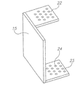
X線非透過性のマーカーボールを有する三次元のターゲット15は、その画像又はその少なくとも一部が、前記Cアーム装置により作成されたビデオ画像に現わされるように、前記患者に対する固定位置に配置されている。前記ターゲットは、前記患者が横たわるベッドに取り付けられていてもよいし、前記患者そのものに取り付けられ又は前記患者の上に配置されていてもよい。実際の位置は、その位置が走査時に固定されている限り、明らかにされる必要がない。このような三次元のプレートは、投影グリッドの使用により前記X線源の位置を測定するターゲットプレートとして、また、前記検出器の上又は前記検出器の近傍に配置されているとき、従来のCアーム装置において歪み補正機能を果たすファントムとして、従来知られている。本発明では、得られたX線透視画像の三次元姿勢が前記ターゲットの位置に対してすなわち前記患者に対して測定されることを可能にするために前記の機能が用いられる。前記ターゲット又はその少なくとも一部は、一連のビデオ画像から得られた二次元のフレームのそれぞれの中に特定されることができ、前記マーカーボールの既知の三次元配置から前記患者に対する前記X線源の姿勢が、好ましくは、各ビデオ画像について測定される。実際には、計算時間を省くため、前記患者に対する前記Cアーム装置の姿勢が、好ましくは、CT形式の三次元データの再構成に最終的に使用される画像について測定される。前記ターゲットは、多くの他の形状を有するものとすることができる。図2に、ターゲットプレートの例を示す。前記ターゲットプレートは、X線非透過性のマーカーボール24を有する、間隔を置かれた2つのプレート22、23であってこれらの位置関係が既知である2つのプレート22、23を有する。
A three-
前記ターゲットプレートは、好ましくは、前記Cアームの経路に沿って得られた前記フレームの全てに現わされる。これは、前記患者及び前記ターゲットが、一般に、前記Cアームの回転中心と同心状に配置されていないため、困難なことである。このため、前記患者及び前記ターゲットが、記録されたフレームの全てにおいてフレーム内にあることを確保することは難しい。他の好適な実施例では、前記ターゲットプレートは、全てのフレームが姿勢評価のために前記ターゲットの少なくとも一部を示すのに十分な大きさの横方向寸法を有する。本実施例によれば、このような前記ターゲットの部分のみの使用が可能である。なぜなら、前記ビデオ画像が、1つのフレームに示された前記ターゲットの部分におけるマーカーの位置と、1又は2以上の前のフレームに示された前記ターゲットの部分における少なくともいくつかの同じマーカー、前のフレームに示された前記ターゲットのより広い部分における少なくともいくつかの同じマーカー又は前のフレームに示された前記ターゲットの全体における少なくともいくつかの同じマーカーとの比較を可能にするからである。このような、既に得られたフレームとの連続的な比較の工程は、いずれかの時点で前記姿勢を測定するために使用される前記ターゲットの部分が、前記Cアームが動いているときに前記ターゲットにおいて移動することがあることを意味する。この段落に記載した位置追跡比較のほかに、前記ターゲットの間隔を置かれた部分が、前記姿勢を規定するために独立して機能することができるように前記ターゲットは、該ターゲットの全体に亘って繰り返されるパターン又は前記ターゲットの各領域の位置がわかるように位置付けられたパターンを用いて構成されていてもよい。 The target plate preferably appears in all of the frames obtained along the path of the C-arm. This is difficult because the patient and the target are generally not arranged concentrically with the center of rotation of the C-arm. For this reason, it is difficult to ensure that the patient and the target are within the frame in all of the recorded frames. In another preferred embodiment, the target plate has a lateral dimension that is large enough for all frames to show at least a portion of the target for posture assessment. According to the present embodiment, it is possible to use only the part of the target. Because the video image has a marker position in the target portion shown in one frame and at least some of the same markers in the target portion shown in one or more previous frames, This is because it allows comparison with at least some of the same markers in a wider portion of the target shown in the frame or at least some of the same markers in the whole of the target shown in the previous frame. Such a step of continuous comparison with the already obtained frame is that the part of the target used to measure the posture at any point in time when the C-arm is moving. This means that the target may move. In addition to the position tracking comparison described in this paragraph, the target can span the entire target so that the spaced portions of the target can function independently to define the attitude. It may be configured using a pattern that is repeated so that the position of each region of the target can be understood.
使用時、前記ターゲットプレートは、前記患者に直接取り付けられることにより又は前記患者が固定されたベッドや手術台に取り付けられることにより、前記患者の関心領域に対して固定された位置に配置される。本発明の他の好適な実施例によれば、前記ターゲットは、三次元構造の半可撓性の表面を有するものとすることができる。前記表面は、前記患者又は前記ベッドの一部を覆うことができ、配置されたとき、画像化される前記患者に対するその位置を維持する。 In use, the target plate is placed in a fixed position relative to the patient's region of interest by being attached directly to the patient or by being attached to a bed or operating table to which the patient is fixed. According to another preferred embodiment of the present invention, the target may have a three-dimensionally structured semi-flexible surface. The surface can cover the patient or a portion of the bed and maintains its position relative to the patient being imaged when placed.
前記X線源は、前記Cアームを手動で動かすことにより又は内蔵された駆動装置の使用により、前記関心領域の上方において回転される。単なる弧状の動き、円形状の動きと前記関心領域の長さ方向に沿った又は前記関心領域の幅方向と交差する連続的な横方向の動きとの組合せ又は揺動のような、いずれかの好適な動きの経路を用いることができる。前記動きは、一定速度である必要はなく、例えば、所望の速度で変更されてもよい。動きは、最終的に必要なデータの収集を妨げることなく、いずれかの位置で一時的に停止されてもよい。前記X線源が前記関心領域を通過するとき、前記X線源と前記検出器との間に介在する人体のX線陰影画像が得られる。このビデオ画像の各フレームに、前記ターゲットの画像、又は広域のターゲットが使用された場合における前記ターゲットの少なくとも一部の画像が表示される。好ましくは、一連のビデオから個別の画像を取得するためにフレーム取込み器が使用される。処理段階において、画像処理アルゴリズムが、1又は2以上の要素に依存する割合で前記ビデオ画像から個別の画像を選択することができる。 The X-ray source is rotated above the region of interest by manually moving the C-arm or by using a built-in drive. Any of a simple arcuate movement, a combination of circular movement and continuous lateral movement along the length of the region of interest or intersecting the width of the region of interest, such as rocking Any suitable path of motion can be used. The movement does not have to be a constant speed, and may be changed at a desired speed, for example. The movement may be temporarily stopped at any position without interfering with the collection of the final required data. When the X-ray source passes through the region of interest, an X-ray shadow image of a human body interposed between the X-ray source and the detector is obtained. In each frame of the video image, an image of the target or an image of at least a part of the target when a wide area target is used is displayed. Preferably, a frame grabber is used to obtain individual images from a series of videos. In the processing stage, an image processing algorithm can select individual images from the video image at a rate depending on one or more factors.
どの画像が選択されるか及びどの程度の頻度で又はどの程度の間隔を置いて画像が選択されるかを決定する初期要素には、以下のものがある。
(1)所望の画像解像度及び精度。要求される画像解像度及び精度が高いほど、前記画像は狭い間隔を置いて選択される。
(2)前記Cアームの動きの瞬間速度。走査速度が遅いほど、前記ビデオ画像からの画像の選択の頻度は少ない。これに対して、走査速度が速いほど、前記画像に多くのモーションブラーが存在し、多くの画像が必要とされる。
(3)前記動きの経路からの誤差。前記Cアームの動きを追跡することにより、前記動きの経路から逸脱した姿勢を有する画像は、異常なものとして除去されることができる。さらに、好ましくは、モーションブラーを低減させるため、再度、隣接するフレームより前記Cアームが低速度で動くフレームが選択される。
(4)前記関心領域の全体の寸法。画像化される前記関心領域が広いほど、高解像度の必要性が低く、前記画像は広い間隔を置いて選択される。
The initial factors that determine which images are selected and how often or at what intervals images are selected include:
(1) Desired image resolution and accuracy. The higher the required image resolution and accuracy, the more closely selected the images are selected.
(2) The instantaneous speed of movement of the C-arm. The slower the scanning speed, the less frequently the image is selected from the video image. On the other hand, the higher the scanning speed, the more motion blur is present in the image and the more images are required.
(3) An error from the movement path. By tracking the movement of the C-arm, an image having a posture deviating from the movement path can be removed as abnormal. Further, preferably, in order to reduce motion blur, a frame in which the C arm moves at a lower speed than an adjacent frame is selected again.
(4) The overall dimensions of the region of interest. The wider the region of interest to be imaged, the lower the need for high resolution and the images are selected at wider intervals.
たとえ走査速度が速くても、画像データの適当な供給を確保するのに十分なフレームが存在するため、前記Cアームの速度は基本的に解像度により制限されない。例えば、毎秒30フレームで収集時間が20秒である場合、600フレームが作成される。このような高速度走査の唯一の問題点は、前記したように、前記フレームがぶれを生じさせることである。 Even if the scanning speed is high, the C-arm speed is basically not limited by the resolution because there are enough frames to ensure an adequate supply of image data. For example, if the collection time is 30 seconds at 30 frames per second, 600 frames are created. The only problem with such high speed scanning is that, as described above, the frame causes blurring.
本発明が、提案された好適な実施例に限定されることはなく、(空間的又は角度的な間隔に基づいて選択される画像について)選択される画像の頻度又は間隔を決定するために他の関連要素が使用されてもよいことは明らかである。 The present invention is not limited to the preferred embodiment proposed, and may be used to determine the frequency or spacing of images selected (for images selected based on spatial or angular spacing). Obviously, related elements may be used.
以下に説明するように、本発明の他の実施例に係る、画像取得処理のための動的モデルの使用は、選択処理が、X線透視装置により作成された画像の実際の質に応じてリアルタイムに調整されることを可能にする。 As described below, the use of a dynamic model for image acquisition processing, according to another embodiment of the present invention, is dependent on the actual quality of the image created by the fluoroscope. Allows to be adjusted in real time.
前記患者に対する前記X線源の姿勢を測定するため、前記ターゲットプレートの画像を解析するコンピュータービジョン(3D画像処理)が行われ、その後、このデータを、三次元情報再構成エンジンに入力するデータセットを作成するために、選択されたフレームから得られた二次元画像データとともに使用する。前記三次元情報再構成エンジンは、各画像についての計算された姿勢とともに、選択された二次元画像を取得し、これらから三次元のデータセットを作成する。前記データセットから、前記患者の身体の所望の断面を示す画像が医師に示される。三次元情報を再構成するために使用されるアルゴリズムは、ART/SART技術等の、従来知られたアルゴリズムとすることができる。 In order to measure the posture of the X-ray source with respect to the patient, computer vision (3D image processing) for analyzing the image of the target plate is performed, and then this data is input to a three-dimensional information reconstruction engine. Is used with the two-dimensional image data obtained from the selected frame. The 3D information reconstruction engine obtains the selected 2D image together with the calculated pose for each image and creates a 3D data set from them. From the data set, an image showing a desired cross section of the patient's body is shown to the physician. The algorithm used to reconstruct the 3D information may be a conventionally known algorithm such as ART / SART technology.
このため、本発明の好適な使用方法の新規な特徴の1つは、従来の、既存のCアームX線透視画像装置からCT形式の三次元データを作成するために三次元のターゲットプレート及び適当な画像データ処理ソフトウェアしか要しないことである。 For this reason, one of the novel features of the preferred method of use of the present invention is that a three-dimensional target plate and suitable for creating three-dimensional data in CT format from a conventional, existing C-arm fluoroscopic imager. Only image data processing software is required.
前記Cアームの動きの追跡のための前記動的モデルの使用は、ビデオデータからの一連の画像の提供により可能とされ、本発明に多くの利益をもたらす。第一に、前記フレームの全体に亘って前記ターゲットプレートの画像を探索しなければならないことに代えて、前記Cアーム装置の画像処理ソフトウェアが、前のフレームの履歴に基づいて少ない画素数の範囲内で認識される期待位置において前記ターゲットプレートの画像を探索することができるため、前記Cアームに関する全ての選択された画像位置において前記ターゲットの画像を探索し、特定する必要がない。このことは、画像解析時間が短縮されるため、装置性能を向上させる。ターゲット探索作業が全体に最適化されるように、前記ターゲット探索作業がより速くなり、より安定するようにするため、前記ターゲットの位置の予測は、個々のマーカーボールの概略位置を予測することを含む。 The use of the dynamic model for tracking the movement of the C-arm is made possible by providing a series of images from video data, which brings many benefits to the present invention. First, instead of having to search for an image of the target plate throughout the frame, the image processing software of the C-arm device has a small pixel range based on the history of the previous frame. The image of the target plate can be searched for at the expected position recognized within, so that it is not necessary to search for and identify the image of the target at all selected image positions for the C-arm. This improves the device performance because the image analysis time is reduced. In order to make the target search task faster and more stable so that the target search task is optimized as a whole, the target position prediction is to predict the approximate position of individual marker balls. Including.
第二に、全てのフレームについて個別に歪み補正関数を計算することに代えて、動的技術が、使用された最初のフレームについてのみ完全な計算を行い、その後、前記Cアーム装置から入手できる動的情報を用いて歪み補正パラメーターを追跡するため、前記動的技術は前記Cアームの歪み補正処理の簡素化を可能にする。このようにして、前記歪み補正パラメーターは、前記動的モデルを用いて前のフレームから予測され、最新のフレームにより僅かに修正される。これは、歪み補正関数のより効率的な計算を可能にし、より円滑かつ正確な、安定した機能をもたらす。 Second, instead of calculating the distortion correction function individually for every frame, the dynamic technique performs a complete calculation only for the first frame used and then the motion available from the C-arm device. Because dynamic information is used to track distortion correction parameters, the dynamic technique allows the C-arm distortion correction process to be simplified. In this way, the distortion correction parameters are predicted from the previous frame using the dynamic model and slightly modified with the latest frame. This allows a more efficient calculation of the distortion correction function, resulting in a smoother, more accurate and stable function.
第三に、前記患者の骨が前記ターゲットプレートのマーカーを隠したときのように、ある前記Cアームの位置について前記マーカーのいくつかが見えない又は不明瞭である場合、見えない又は不明瞭なマーカー位置を、欠陥データを有するフレームの前後の隣接するフレームのマーカー位置に関するデータから補うことができるため、動的な方法は安定性に優れる。 Third, if some of the markers are invisible or obscure for the position of the C-arm, such as when the patient's bone has hidden the markers on the target plate, they are invisible or obscure Since the marker position can be supplemented from data related to the marker position of adjacent frames before and after the frame having defect data, the dynamic method is excellent in stability.
さらに、フレームの選択をフレームデータの質に応じて行うことができるため、一連のビデオ画像の取得は画像精度の向上を可能にする。細部が基準以下であるフレームは、前記Cアームの動きの飛び越しにより、CT形式の三次元データの再構成への使用を回避されることができる。また、一連のビデオ画像が細部の予測を可能にするため、例えば、不明瞭な又はノイズの多い画像により、使用されたフレームのいくつかにおける期待位置に前記細部が発見されなかった場合、欠陥のある前記細部を示すフレームは、異常なものとして拒絶されることができる又は前記フレームの質と所望のデータセットの一部として使用される前記フレームの貢献とを高めるために信号処理ソフトウェアにより修正されることができる。 Furthermore, since frame selection can be performed according to the quality of the frame data, acquisition of a series of video images enables improvement in image accuracy. Frames whose details are below the standard can be avoided from being used to reconstruct CT format 3D data by skipping the movement of the C-arm. Also, because a series of video images allows for prediction of details, if the details are not found in the expected position in some of the used frames, for example due to unclear or noisy images, Frames that show certain details can be rejected as abnormal or modified by signal processing software to increase the quality of the frames and the contribution of the frames used as part of the desired data set Can.
前記ビデオ画像は、必要に応じて、各フレームについて測定された姿勢の修正を可能にする。予定された動きが停止したにもかかわらず、前記Cアームの動きが連続的であると仮定されるため、短時間に各フレームの前記姿勢を予測することができる。また、いずれかのフレームについての前記ターゲットの解析が異常な姿勢を示した場合、隣接するフレームから測定された姿勢の挿入により決定された仮定の補正姿勢を使用することができる。 The video image allows correction of the measured posture for each frame, if necessary. Since the movement of the C-arm is assumed to be continuous despite the scheduled movement being stopped, the posture of each frame can be predicted in a short time. Also, if the target analysis for any frame shows an abnormal posture, an assumed corrected posture determined by insertion of postures measured from adjacent frames can be used.
前記画像処理ソフトウェアのぶれ低減方向フィルター技術の使用が、速過ぎるCアームの動きのための修正を可能にする。ビデオ技術分野においてぶれ低減フィルターが知られているが、本発明において使用された動的モデルが一連のフレームの間の動きの方向及び速度について良好な情報を提供し、これによりぶれ低減の水準の向上を可能にするため、本発明において使用された技術は、標準的なビデオぶれ低減方法より効果的なものとなる。 Use of the image processing software's blur reduction directional filter technology allows correction for too fast C-arm movement. Although blur reduction filters are known in the video arts, the dynamic model used in the present invention provides good information about the direction and speed of motion during a series of frames, thereby reducing the level of blur reduction. To enable improvement, the technique used in the present invention is more effective than standard video blur reduction methods.
上記の特徴の全ての組合せは、ビデオに基づくデータ取得を、別個の画像化が比較的少ない方向付けのみからなされる従来のCアームCT形式装置より正確にする。 All combinations of the above features make video-based data acquisition more accurate than conventional C-arm CT type devices where separate imaging is only done with relatively little orientation.
既存のCアームX線透視装置からの未加工のビデオ情報の使用から生じる1つの問題点は、前記ビデオをTV規格に適合させるため及びTVモニターへの表示のため、前記ビデオが、一般に、インターレース方式によりアナログビデオ規格の1つに出力されることである。通常のビデオ表示に使用されるとき、このようなインターレース方式は問題を生じさせない。しかし、本発明では、前記ビデオのフレームから位置データが抽出されるが、インターレース方式による奇数フィールド及び偶数フィールドが前記Cアームの動きの異なる位置において取得されるため、前記奇数フィールドと前記偶数フィールドとの間に大きな差異が生じる。このため、特徴の縁部が前記奇数フィールドと前記偶数フィールドとの間で異なる位置に現れるのみならず、前記ターゲットの解析により測定される前記画像そのものの位置も異なる。この問題の1つの解決策は、前記ビデオ画像の使用前に前記フレームのインターレースを解除することである。インターレースの解除が、一般に、前記画像の質を低下させるため、代替技術として、本発明において使用されるビデオ処理ソフトウェアは、各フィールドが連続的となるように、各フィールドを個々に処理する。この方法により、前記フィールドの前記姿勢に関する位置データは各フィールドについて個々に正確に計算されることができ、再構成の段階で、前記フィールドの関連するラインのみが前記フィールドの三次元の姿勢とともに再構成に使用される。インターレース方式のビデオ及びインターレース方式でないビデオの双方を本発明において使用できるため、本願において使用され、特許請求の範囲に記載されたフレームの語が、特に説明しないときでも、インターレース方式のビデオのフィールドを含み、本願が、画像データを取得するフレーム又はフィールドのいずれか一方に限定されないことは明らかである。 One problem that arises from the use of raw video information from existing C-arm fluoroscopes is that the video is generally interlaced in order to conform the video to the TV standard and for display on a TV monitor. It is to be output to one of the analog video standards depending on the system. Such interlacing schemes do not cause problems when used for normal video display. However, in the present invention, position data is extracted from the video frame, but since the odd field and the even field by the interlace method are acquired at different positions of the movement of the C-arm, the odd field and the even field are There is a big difference between For this reason, not only does the edge of the feature appear at a different position between the odd field and the even field, but also the position of the image itself measured by the analysis of the target is different. One solution to this problem is to deinterlace the frame before using the video image. As de-interlacing generally degrades the quality of the image, as an alternative, the video processing software used in the present invention processes each field individually so that each field is continuous. In this way, position data relating to the pose of the field can be accurately calculated individually for each field, and at the reconstruction stage, only the relevant lines of the field are reconstructed along with the three-dimensional pose of the field. Used for configuration. Since both interlaced video and non-interlaced video can be used in the present invention, even if the word of the frame used in the present application and recited in the claims does not specifically describe the field of the interlaced video, In addition, it is obvious that the present application is not limited to either one of the frame or the field from which the image data is acquired.
図3は、Cアームに基づくCT装置の構成要素のブロック図であり、前記CT装置の画像処理モジュール30の主な機能ユニットを示す。図3に示した装置は、画像選択が行われる前に全てのフレーム又はフィールドの姿勢が測定される好適な実施例である。一般にイメージインテンシファイア又はフラットパネル検出器である検出器31は、その出力信号を姿勢測定ユニット32に送る。姿勢測定ユニット32は、前記フレーム(又はフィールド)の中に前記ターゲットを検索し、前記フレームの中の前記マーカーボールの位置から前記フレームにおける前記患者に対する前記X線源の姿勢を測定する。画像処理モジュール30のソフトウェアの中でフレームセレクター33が前記ビデオ画像からフレームを選択する。角度姿勢、走査速度又は他の適当な基準に関する前記した基準のいずれかに応じてフレームが選択される。このユニットを「フレームセレクター」として説明したが、この語は、前記フレームの別個のフィールドが処理される実施例のための機能ユニットを含むことを明らかである。選択されたフレーム(又はフレームのフィールド)のそれぞれについて、前記フレームセレクターに続く画像処理ユニット34は、選択された画像のみを処理する、典型的には、これらを歪み補正し、正常化する。選択されたフレームから得られた二次元画像データを、前記選択されたフレームのそれぞれについて既に取得された姿勢情報とともに使用して、画像処理ユニット34は、三次元情報再構成エンジン35に入力するデータセットを作成する。不足する特徴を有する画像の修正操作及び歪み補正機能予測操作を行えるように、画像処理ユニット34は、好ましくは、前の画像及び(又は)連続する画像の内容の解析により、選択された画像の特徴を予測する画像比較モジュール(図示せず)を含む。また、画像処理ユニット34は、好ましくは、画像データにおけるCアームの動きの影響を低減させる画像ぶれ補正ユニットを含む。再構成エンジン35の出力データは装置メモリー36へ転送され、前記出力データは、装置メモリー36から、従来のCT画像技術分野において知られている前記患者の所望の断面画像又は三次元画像を医師に対してディスプレー37に表示するために取り出される。再構成されたデータは、例えば、DICOM形式を用いて、さらに処理し又は解析する他の装置に送られてもよい。
FIG. 3 is a block diagram of the components of the CT apparatus based on the C-arm, showing the main functional units of the
本発明の他の好適な実施例によれば、姿勢の測定がフレームの選択前に全てのフレーム(フィールド)について行われる必要がないように画像の選択は走査位置に基づくことなく行われる。この実施例では、図3に示したフレームセレクター33は、この実施例に適合する選択基準を有し、姿勢測定ユニット32の前に位置する。
According to another preferred embodiment of the present invention, the image selection is made without being based on the scanning position so that the posture measurement need not be performed for every frame (field) before the frame selection. In this embodiment, the
本発明の好適な実施例に係る方法のフローチャートである図4に示すように、Cアームに基づくCT画像装置はその出力データを作成する。前記フローチャートは、本発明の方法に特有の好適なステップのみを示す。全てのCアーム画像処理と同様に、図4に示した本発明の方法のステップを行う前にぶれ補正ファントムがCアームに取り付けられ、鮮明な画像が撮られる。ファントムボールを追跡するため及び画像を正常化させるためにキャリブレーション情報が使用される。ステップ40において三次元のターゲットを、画像化される患者に対する所定の位置に固定する。その後、ステップ41において前記Cアームを前記患者の関心領域の上方において所望の経路で動かし、その間に、ステップ42において一連のビデオ画像を取得する。ステップ43において、画像データ及びこれに関連する姿勢を抽出するため、図3に示した信号処理ユニットによりフレームを処理する。ステップ44において前記ビデオ画像からフレームを選択する。前記フレームはその角度に基づいて便宜的に選択する、例えば、フレームの選択は1度毎のような一定の角度間隔で行う。フレームは、前記した基準により選択してもよい。ステップ45において、現時点で選択されたフレームの前のフレームにおいて決定された歪み補正関数を、現時点で選択されたフレームのファントム画像から得られたデータを用いて更新し、選択されたフレームを歪み補正し、正常化する。ステップ46においてこのデータを装置メモリーユニットに送信し、該装置メモリーユニットに、蓄積された残りの二次元データとともに保存する。ステップ47において、CT形式の情報を出力するために有用な三次元データを作成するために必要な量及び質のデータを提供するために十分なフレーム及びその姿勢が蓄積されているか否かについて判断する。十分なデータが蓄積されていない場合、ステップ44においてより多くのフレームを選択することを決定する。十分なデータが蓄積されている場合、前記Cアームがその経路の終点に到達した場合又はオペレーターが走査終了の信号を送った場合、前記データを再構成エンジンに送信し、ステップ48において、CT形式の三次元画像を出力するのに適した三次元データに変換する。ステップ48において前記再構成エンジンにより作成された前記三次元データを質及び量について分析し、必要に応じて、例えば、良好な再構成のための特定の方向からの十分な情報がない場合、ステップ49において、再構成時にフレームセレクター44からの追加のフレームを要求する。最後に、ステップ50において前記三次元データを医師の要求に応じて表示する。
As shown in FIG. 4, which is a flowchart of a method according to a preferred embodiment of the present invention, a CT image device based on the C-arm creates its output data. The flow chart shows only the preferred steps specific to the method of the invention. As with all C-arm image processing, a blur correction phantom is attached to the C-arm and a sharp image is taken prior to performing the method steps of the present invention shown in FIG. Calibration information is used to track the phantom ball and to normalize the image. In
フレームの選択が姿勢測定の解析の前に行われる実施例では、前記フローチャートのステップの順番は修正される。 In an embodiment where the frame selection is performed before the posture measurement analysis, the order of the steps in the flowchart is modified.
標準的なCアーム装置は、一般に、画像化される物体の非透過性の変化に応じてX線源の電圧及び電流を修正することにより、強度、コントラスト・明るさを自動制御する。これは、全体の明るさが類似する画像を得るためになされる。前記Cアーム装置は、前記X線源の強度パラメーターを調節するために画像の積分強度を利用する。 Standard C-arm devices generally automatically control intensity, contrast and brightness by modifying the voltage and current of the x-ray source in response to changes in the opacity of the object being imaged. This is done to obtain images with similar overall brightness. The C-arm device uses the integrated intensity of the image to adjust the intensity parameter of the X-ray source.
強度の変化は、画像化される物体の見かけの大きさを変化させることができる、例えば、より高強度の入射ビームほど、骨のような非透過性の物体の外縁部を容易に通過し、前記外縁部を透明にし、前記骨を細く見せる。このため、同一の物体が、異なるフレームにおいて異なる強度を有するように、強度の変化は物体の実際の外観を変化させることができる。3D再構成処理が物体密度の関数として画像強度の均一性に基づくため、画像は共通のパラメーターへ正常化される必要がある。 The change in intensity can change the apparent size of the object being imaged, e.g., a higher intensity incident beam will easily pass through the outer edge of an impermeable object such as bone, The outer edge is transparent, and the bone is made thin. Thus, a change in intensity can change the actual appearance of the object so that the same object has different intensities in different frames. Since the 3D reconstruction process is based on image intensity uniformity as a function of object density, the images need to be normalized to a common parameter.
このため、照明強度の変化にかかわらず、各画像において特徴の大きさを正常化するため、前記X線源の強度レベルを監視する必要がある。 For this reason, it is necessary to monitor the intensity level of the X-ray source in order to normalize the feature size in each image regardless of the change in illumination intensity.
図5に、本発明の他の実施例に係る新規の強度センサー又はターゲット50を示す。前記強度センサーは、X線に対する異なる既知の吸収性を有する少なくとも3つの領域を備える。図5に示した実施例では、3つの領域51、52、53は、同心円状であるが、3つの領域の全てがX線透視装置により容易に画像化される限り、前記領域の形状に制限はない。前記領域の間の吸収性の比率が既知であるため、2つの既知の比率が存在する。前記領域の個々の階調レベルは強度の関数であるが、前記比率は一定である。ベールの法則(数式1)を用いて、異なる領域の強度を測定することにより、I0について解くことができる。
FIG. 5 shows a novel intensity sensor or target 50 according to another embodiment of the present invention. The intensity sensor comprises at least three regions with different known absorbencies for X-rays. In the embodiment shown in FIG. 5, the three
![]()
![]()
前記ターゲットは、空気以外の材料の上に配置される。この場合、ベールの方程式は、その材料の影響を表す新たな未知数αを有する(数式2)。少なくとも3つの領域が存在するため、I0及びαの双方について解くことができる。 The target is disposed on a material other than air. In this case, the Beer equation has a new unknown α representing the influence of the material (Equation 2). Since there are at least three regions, it can be solved for both I 0 and α.
![]()
![]()
正常化をより安定させるため、前記ターゲットがいくつかの異なる材料の上にある場合、前記画像の周囲のいくつかのターゲット、場合によっては、3より多い領域を有するいくつかのターゲットを用いることが好ましい。 To make the normalization more stable, if the target is on several different materials, use several targets around the image, possibly some targets with more than three areas preferable.
本発明を、一般に知られたCアーム装置に関して説明した。Cアームの語が、C形状のアームを有する装置に限定されず、一般に、X線源と、これに固定された、画像化される患者の周囲において移動する検出ユニットとから二次元画像を作成するX線画像装置を含むことは明らかである。 The invention has been described with reference to commonly known C-arm devices. The term C-arm is not limited to devices having a C-shaped arm, but generally creates a two-dimensional image from an x-ray source and a detection unit fixed to it and moving around the patient to be imaged. Obviously, it includes an X-ray imaging device.
本発明が、本明細書に記載した事項に限定されないことは、当業者に明らかである。本発明の範囲は、本明細書に記載した様々な特徴のコンビネーション及びサブコンビネーションに加え、上記の記載から当業者が想到する、先行技術にない変更及び修正を含む。 It will be apparent to those skilled in the art that the present invention is not limited to what has been described herein. The scope of the present invention includes various features and combinations described herein, as well as variations and modifications not found in the prior art that will occur to those skilled in the art from the foregoing description.
12 X線源
14、31 検出器
15、50 ターゲット
16 患者
24 マーカーボール
34 画像処理ユニット
35 再構成エンジン
12
Claims (12)
三次元パターンに配置されたX線非透過性の一連の複数のマーカーを有するターゲットを、その少なくとも一部が前記画像装置により画像化されるように前記患者に対する固定位置に配置すること、
前記Cアームを手動で動かすこと、
前記Cアームが動いているときに前記X線カメラから前記患者の前記関心領域の一連のビデオ画像を取得すること、
前記ターゲットの画像パターンにおける前記マーカーの画像の位置を解析することにより、前記ビデオ画像の少なくともいくつかについて前記患者に対する前記Cアームの姿勢を測定すること、
前記ビデオ画像から複数のビデオ画像を選択すること、
前記患者の前記関心領域の三次元画像データを再構成するために、選択されたビデオ画像及び測定された姿勢を使用することを含む、三次元画像データの作成方法。 An imaging device having an X-ray source and an X-ray camera connected to the X-ray source by a C-arm, and imaging a region of interest of a patient disposed between the X-ray source and the X-ray camera Preparing an image device to
Placing a target having a series of radiopaque markers arranged in a three-dimensional pattern in a fixed position relative to the patient such that at least a portion thereof is imaged by the imaging device;
Manually moving the C-arm;
Acquiring a series of video images of the region of interest of the patient from the X-ray camera when the C-arm is moving;
Measuring the position of the C-arm with respect to the patient for at least some of the video images by analyzing the position of the image of the marker in the image pattern of the target;
Selecting a plurality of video images from the video images;
A method of creating 3D image data comprising using a selected video image and a measured pose to reconstruct 3D image data of the region of interest of the patient.
Applications Claiming Priority (5)
| Application Number | Priority Date | Filing Date | Title |
|---|---|---|---|
| US84675006P | 2006-09-25 | 2006-09-25 | |
| US60/846,750 | 2006-09-25 | ||
| US90787407P | 2007-04-20 | 2007-04-20 | |
| US60/907,874 | 2007-04-20 | ||
| PCT/IL2007/001193 WO2008038283A2 (en) | 2006-09-25 | 2007-09-25 | C-arm computerized tomography system |
Publications (3)
| Publication Number | Publication Date |
|---|---|
| JP2010520770A JP2010520770A (en) | 2010-06-17 |
| JP2010520770A5 JP2010520770A5 (en) | 2014-04-17 |
| JP5609112B2 true JP5609112B2 (en) | 2014-10-22 |
Family
ID=39230676
Family Applications (1)
| Application Number | Title | Priority Date | Filing Date |
|---|---|---|---|
| JP2009529855A Expired - Fee Related JP5609112B2 (en) | 2006-09-25 | 2007-09-25 | How to create 3D image data |
Country Status (6)
| Country | Link |
|---|---|
| US (1) | US9044190B2 (en) |
| EP (1) | EP2074383B1 (en) |
| JP (1) | JP5609112B2 (en) |
| KR (1) | KR101525259B1 (en) |
| CN (1) | CN103961130B (en) |
| WO (1) | WO2008038283A2 (en) |
Families Citing this family (156)
| Publication number | Priority date | Publication date | Assignee | Title |
|---|---|---|---|---|
| US10893912B2 (en) | 2006-02-16 | 2021-01-19 | Globus Medical Inc. | Surgical tool systems and methods |
| US10653497B2 (en) | 2006-02-16 | 2020-05-19 | Globus Medical, Inc. | Surgical tool systems and methods |
| US10357184B2 (en) | 2012-06-21 | 2019-07-23 | Globus Medical, Inc. | Surgical tool systems and method |
| WO2008038284A2 (en) | 2006-09-25 | 2008-04-03 | Mazor Surgical Technologies Ltd. | Ct-free spinal surgical imaging system |
| JP5239585B2 (en) * | 2008-07-28 | 2013-07-17 | 株式会社島津製作所 | X-ray imaging device |
| DE102009015144A1 (en) * | 2009-03-26 | 2010-09-30 | Siemens Aktiengesellschaft | Method for obtaining mapping rule of point in three dimensional space on image plane for X-ray image recoding system, involves utilizing mapping rule for defining basic value set, where rule is delivered for positioning interpolation values |
| JP5567399B2 (en) | 2009-06-22 | 2014-08-06 | 株式会社モリタ製作所 | Medical X-ray CT system |
| DE102010020350B4 (en) * | 2010-05-12 | 2017-02-23 | Siemens Healthcare Gmbh | Method for positioning the focus of a gradient field and treatment device |
| KR101188715B1 (en) | 2010-10-04 | 2012-10-09 | 한국과학기술연구원 | 3 dimension tracking system for surgery simulation and localization sensing method using the same |
| US9308050B2 (en) | 2011-04-01 | 2016-04-12 | Ecole Polytechnique Federale De Lausanne (Epfl) | Robotic system and method for spinal and other surgeries |
| EP2852326B1 (en) | 2012-05-22 | 2018-12-05 | Mazor Robotics Ltd. | On-site verification of implant positioning |
| US10624710B2 (en) | 2012-06-21 | 2020-04-21 | Globus Medical, Inc. | System and method for measuring depth of instrumentation |
| US10350013B2 (en) | 2012-06-21 | 2019-07-16 | Globus Medical, Inc. | Surgical tool systems and methods |
| US11864745B2 (en) | 2012-06-21 | 2024-01-09 | Globus Medical, Inc. | Surgical robotic system with retractor |
| US10231791B2 (en) | 2012-06-21 | 2019-03-19 | Globus Medical, Inc. | Infrared signal based position recognition system for use with a robot-assisted surgery |
| WO2013192598A1 (en) | 2012-06-21 | 2013-12-27 | Excelsius Surgical, L.L.C. | Surgical robot platform |
| US11045267B2 (en) | 2012-06-21 | 2021-06-29 | Globus Medical, Inc. | Surgical robotic automation with tracking markers |
| US11896446B2 (en) | 2012-06-21 | 2024-02-13 | Globus Medical, Inc | Surgical robotic automation with tracking markers |
| US11857149B2 (en) | 2012-06-21 | 2024-01-02 | Globus Medical, Inc. | Surgical robotic systems with target trajectory deviation monitoring and related methods |
| US10842461B2 (en) | 2012-06-21 | 2020-11-24 | Globus Medical, Inc. | Systems and methods of checking registrations for surgical systems |
| US10136954B2 (en) | 2012-06-21 | 2018-11-27 | Globus Medical, Inc. | Surgical tool systems and method |
| US11963755B2 (en) | 2012-06-21 | 2024-04-23 | Globus Medical Inc. | Apparatus for recording probe movement |
| US11793570B2 (en) | 2012-06-21 | 2023-10-24 | Globus Medical Inc. | Surgical robotic automation with tracking markers |
| US11974822B2 (en) | 2012-06-21 | 2024-05-07 | Globus Medical Inc. | Method for a surveillance marker in robotic-assisted surgery |
| US11317971B2 (en) | 2012-06-21 | 2022-05-03 | Globus Medical, Inc. | Systems and methods related to robotic guidance in surgery |
| US11786324B2 (en) | 2012-06-21 | 2023-10-17 | Globus Medical, Inc. | Surgical robotic automation with tracking markers |
| US11857266B2 (en) | 2012-06-21 | 2024-01-02 | Globus Medical, Inc. | System for a surveillance marker in robotic-assisted surgery |
| US11607149B2 (en) | 2012-06-21 | 2023-03-21 | Globus Medical Inc. | Surgical tool systems and method |
| US11589771B2 (en) | 2012-06-21 | 2023-02-28 | Globus Medical Inc. | Method for recording probe movement and determining an extent of matter removed |
| US11864839B2 (en) | 2012-06-21 | 2024-01-09 | Globus Medical Inc. | Methods of adjusting a virtual implant and related surgical navigation systems |
| US11253327B2 (en) | 2012-06-21 | 2022-02-22 | Globus Medical, Inc. | Systems and methods for automatically changing an end-effector on a surgical robot |
| US11399900B2 (en) | 2012-06-21 | 2022-08-02 | Globus Medical, Inc. | Robotic systems providing co-registration using natural fiducials and related methods |
| US10874466B2 (en) | 2012-06-21 | 2020-12-29 | Globus Medical, Inc. | System and method for surgical tool insertion using multiaxis force and moment feedback |
| US11298196B2 (en) | 2012-06-21 | 2022-04-12 | Globus Medical Inc. | Surgical robotic automation with tracking markers and controlled tool advancement |
| US11116576B2 (en) | 2012-06-21 | 2021-09-14 | Globus Medical Inc. | Dynamic reference arrays and methods of use |
| US11395706B2 (en) | 2012-06-21 | 2022-07-26 | Globus Medical Inc. | Surgical robot platform |
| US10799298B2 (en) | 2012-06-21 | 2020-10-13 | Globus Medical Inc. | Robotic fluoroscopic navigation |
| US10758315B2 (en) | 2012-06-21 | 2020-09-01 | Globus Medical Inc. | Method and system for improving 2D-3D registration convergence |
| US10646280B2 (en) | 2012-06-21 | 2020-05-12 | Globus Medical, Inc. | System and method for surgical tool insertion using multiaxis force and moment feedback |
| EP2772189A1 (en) * | 2013-02-28 | 2014-09-03 | Koninklijke Philips N.V. | Apparatus and method for determining vital sign information from a subject |
| US10070828B2 (en) | 2013-03-05 | 2018-09-11 | Nview Medical Inc. | Imaging systems and related apparatus and methods |
| US10846860B2 (en) | 2013-03-05 | 2020-11-24 | Nview Medical Inc. | Systems and methods for x-ray tomosynthesis image reconstruction |
| GB201305658D0 (en) | 2013-03-27 | 2013-05-15 | Nikon Metrology Nv | Registration object, correction method and apparatus for computed radiographic tomography |
| US9283048B2 (en) | 2013-10-04 | 2016-03-15 | KB Medical SA | Apparatus and systems for precise guidance of surgical tools |
| EP3084720A1 (en) * | 2013-12-22 | 2016-10-26 | Analogic Corporation | Inspection system and method |
| EP3094272B1 (en) | 2014-01-15 | 2021-04-21 | KB Medical SA | Notched apparatus for guidance of an insertable instrument along an axis during spinal surgery |
| WO2015121311A1 (en) | 2014-02-11 | 2015-08-20 | KB Medical SA | Sterile handle for controlling a robotic surgical system from a sterile field |
| EP3134022B1 (en) | 2014-04-24 | 2018-01-10 | KB Medical SA | Surgical instrument holder for use with a robotic surgical system |
| WO2015193479A1 (en) | 2014-06-19 | 2015-12-23 | KB Medical SA | Systems and methods for performing minimally invasive surgery |
| US10357257B2 (en) | 2014-07-14 | 2019-07-23 | KB Medical SA | Anti-skid surgical instrument for use in preparing holes in bone tissue |
| US10765438B2 (en) | 2014-07-14 | 2020-09-08 | KB Medical SA | Anti-skid surgical instrument for use in preparing holes in bone tissue |
| US9986983B2 (en) | 2014-10-31 | 2018-06-05 | Covidien Lp | Computed tomography enhanced fluoroscopic system, device, and method of utilizing the same |
| JP6731920B2 (en) | 2014-12-02 | 2020-07-29 | カーベー メディカル エスアー | Robot-assisted volume removal during surgery |
| US10631794B2 (en) * | 2014-12-11 | 2020-04-28 | Ghansham Das AGARWAL | Device for externally marking the location of organs on skin during a CAT scan |
| JP6707542B2 (en) * | 2014-12-18 | 2020-06-10 | コーニンクレッカ フィリップス エヌ ヴェKoninklijke Philips N.V. | Imaging system for imaging an elongated region of interest in an object |
| RU2695099C2 (en) * | 2014-12-31 | 2019-07-19 | Тсинхуа Юниверсити | X-ray beam intensity monitoring device and x-ray radiation monitoring system |
| US10013808B2 (en) | 2015-02-03 | 2018-07-03 | Globus Medical, Inc. | Surgeon head-mounted display apparatuses |
| EP3258872B1 (en) | 2015-02-18 | 2023-04-26 | KB Medical SA | Systems for performing minimally invasive spinal surgery with a robotic surgical system using a percutaneous technique |
| DE102016201701A1 (en) | 2015-02-24 | 2016-08-25 | Siemens Aktiengesellschaft | Mobile, motor-driven medical device and method for operating such a device |
| US10058394B2 (en) | 2015-07-31 | 2018-08-28 | Globus Medical, Inc. | Robot arm and methods of use |
| US10646298B2 (en) | 2015-07-31 | 2020-05-12 | Globus Medical, Inc. | Robot arm and methods of use |
| US10674982B2 (en) | 2015-08-06 | 2020-06-09 | Covidien Lp | System and method for local three dimensional volume reconstruction using a standard fluoroscope |
| US10702226B2 (en) | 2015-08-06 | 2020-07-07 | Covidien Lp | System and method for local three dimensional volume reconstruction using a standard fluoroscope |
| US10716525B2 (en) | 2015-08-06 | 2020-07-21 | Covidien Lp | System and method for navigating to target and performing procedure on target utilizing fluoroscopic-based local three dimensional volume reconstruction |
| US10080615B2 (en) | 2015-08-12 | 2018-09-25 | Globus Medical, Inc. | Devices and methods for temporary mounting of parts to bone |
| EP3344179B1 (en) | 2015-08-31 | 2021-06-30 | KB Medical SA | Robotic surgical systems |
| US10034716B2 (en) | 2015-09-14 | 2018-07-31 | Globus Medical, Inc. | Surgical robotic systems and methods thereof |
| US9903958B2 (en) * | 2015-09-23 | 2018-02-27 | Prismatic Sensors Ab | Obtaining measurement information from an edge-on X-ray detector and determining the orientation of an edge-on X-ray detector with respect to the direction of incoming X-rays |
| US9771092B2 (en) | 2015-10-13 | 2017-09-26 | Globus Medical, Inc. | Stabilizer wheel assembly and methods of use |
| EP3373815A4 (en) | 2015-11-13 | 2019-07-17 | Stryker European Holdings I, LLC | Adaptive positioning technology |
| US11172895B2 (en) | 2015-12-07 | 2021-11-16 | Covidien Lp | Visualization, navigation, and planning with electromagnetic navigation bronchoscopy and cone beam computed tomography integrated |
| US10842453B2 (en) | 2016-02-03 | 2020-11-24 | Globus Medical, Inc. | Portable medical imaging system |
| US11883217B2 (en) | 2016-02-03 | 2024-01-30 | Globus Medical, Inc. | Portable medical imaging system and method |
| US11058378B2 (en) | 2016-02-03 | 2021-07-13 | Globus Medical, Inc. | Portable medical imaging system |
| US10448910B2 (en) | 2016-02-03 | 2019-10-22 | Globus Medical, Inc. | Portable medical imaging system |
| US10117632B2 (en) | 2016-02-03 | 2018-11-06 | Globus Medical, Inc. | Portable medical imaging system with beam scanning collimator |
| US10866119B2 (en) | 2016-03-14 | 2020-12-15 | Globus Medical, Inc. | Metal detector for detecting insertion of a surgical device into a hollow tube |
| EP3241518A3 (en) | 2016-04-11 | 2018-01-24 | Globus Medical, Inc | Surgical tool systems and methods |
| CN205849553U (en) | 2016-06-08 | 2017-01-04 | 北京天智航医疗科技股份有限公司 | A kind of location of operation scale |
| US10492755B2 (en) * | 2016-07-13 | 2019-12-03 | Carestream Health, Inc. | Calibration phantom comprising a reflectance calibration target and a plurality of radio-opaque markers |
| US11051886B2 (en) | 2016-09-27 | 2021-07-06 | Covidien Lp | Systems and methods for performing a surgical navigation procedure |
| US11039893B2 (en) | 2016-10-21 | 2021-06-22 | Globus Medical, Inc. | Robotic surgical systems |
| EP3531918A4 (en) * | 2016-10-31 | 2020-09-16 | Body Vision Medical Ltd. | Jigs for use in medical imaging and methods for using thereof |
| EP3351202B1 (en) | 2017-01-18 | 2021-09-08 | KB Medical SA | Universal instrument guide for robotic surgical systems |
| JP2018114280A (en) | 2017-01-18 | 2018-07-26 | ケービー メディカル エスアー | Universal instrument guide for robotic surgical system, surgical instrument system, and method of using them |
| JP7233841B2 (en) | 2017-01-18 | 2023-03-07 | ケービー メディカル エスアー | Robotic Navigation for Robotic Surgical Systems |
| US11071594B2 (en) | 2017-03-16 | 2021-07-27 | KB Medical SA | Robotic navigation of robotic surgical systems |
| EP3621545B1 (en) | 2017-05-10 | 2024-02-21 | MAKO Surgical Corp. | Robotic spine surgery system |
| US11033341B2 (en) | 2017-05-10 | 2021-06-15 | Mako Surgical Corp. | Robotic spine surgery system and methods |
| WO2018227449A1 (en) | 2017-06-15 | 2018-12-20 | Shanghai United Imaging Healthcare Co., Ltd. | Imaging systems and methods thereof |
| EP3421086B1 (en) * | 2017-06-28 | 2020-01-15 | OptiNav Sp. z o.o. | Determination of geometrical information about a medical treatment arrangement comprising a rotatable treatment radiation source unit |
| US10699448B2 (en) | 2017-06-29 | 2020-06-30 | Covidien Lp | System and method for identifying, marking and navigating to a target using real time two dimensional fluoroscopic data |
| CN110621985B (en) * | 2017-07-03 | 2022-03-11 | 株式会社岛津制作所 | X-ray computed tomography apparatus |
| US10675094B2 (en) | 2017-07-21 | 2020-06-09 | Globus Medical Inc. | Robot surgical platform |
| EP3685350A4 (en) | 2017-09-22 | 2021-05-19 | Nview Medical Inc. | Image reconstruction using machine learning regularizers |
| WO2019075074A1 (en) | 2017-10-10 | 2019-04-18 | Covidien Lp | System and method for identifying and marking a target in a fluoroscopic three-dimensional reconstruction |
| US11357548B2 (en) | 2017-11-09 | 2022-06-14 | Globus Medical, Inc. | Robotic rod benders and related mechanical and motor housings |
| US11794338B2 (en) | 2017-11-09 | 2023-10-24 | Globus Medical Inc. | Robotic rod benders and related mechanical and motor housings |
| US10898252B2 (en) | 2017-11-09 | 2021-01-26 | Globus Medical, Inc. | Surgical robotic systems for bending surgical rods, and related methods and devices |
| US11134862B2 (en) | 2017-11-10 | 2021-10-05 | Globus Medical, Inc. | Methods of selecting surgical implants and related devices |
| EP3713491A4 (en) | 2017-11-22 | 2021-12-22 | Mazor Robotics Ltd. | A method for verifying hard tissue location using implant imaging |
| FR3076203B1 (en) | 2017-12-28 | 2019-12-20 | Thales | METHOD AND SYSTEM FOR CALIBRATING AN X-RAY IMAGING SYSTEM |
| US10905498B2 (en) | 2018-02-08 | 2021-02-02 | Covidien Lp | System and method for catheter detection in fluoroscopic images and updating displayed position of catheter |
| AU2019200594B2 (en) * | 2018-02-08 | 2020-05-28 | Covidien Lp | System and method for local three dimensional volume reconstruction using a standard fluoroscope |
| US11364004B2 (en) * | 2018-02-08 | 2022-06-21 | Covidien Lp | System and method for pose estimation of an imaging device and for determining the location of a medical device with respect to a target |
| US20190254753A1 (en) | 2018-02-19 | 2019-08-22 | Globus Medical, Inc. | Augmented reality navigation systems for use with robotic surgical systems and methods of their use |
| US10573023B2 (en) | 2018-04-09 | 2020-02-25 | Globus Medical, Inc. | Predictive visualization of medical imaging scanner component movement |
| US11337742B2 (en) | 2018-11-05 | 2022-05-24 | Globus Medical Inc | Compliant orthopedic driver |
| US11278360B2 (en) | 2018-11-16 | 2022-03-22 | Globus Medical, Inc. | End-effectors for surgical robotic systems having sealed optical components |
| US11602402B2 (en) | 2018-12-04 | 2023-03-14 | Globus Medical, Inc. | Drill guide fixtures, cranial insertion fixtures, and related methods and robotic systems |
| US11744655B2 (en) | 2018-12-04 | 2023-09-05 | Globus Medical, Inc. | Drill guide fixtures, cranial insertion fixtures, and related methods and robotic systems |
| EP3924938A1 (en) | 2019-02-15 | 2021-12-22 | Koninklijke Philips N.V. | X-ray ripple markers for x-ray calibration |
| US11918406B2 (en) | 2019-02-15 | 2024-03-05 | Koninklijke Philips N.V. | Marker registration correction by virtual model manipulation |
| US11931198B2 (en) | 2019-02-15 | 2024-03-19 | Koninklijke Philips N.V. | X-ray calibration for display overlays onto X-ray images |
| WO2020178957A1 (en) * | 2019-03-04 | 2020-09-10 | 日本電気株式会社 | Image processing device, image processing method, and program recording medium |
| US11918313B2 (en) | 2019-03-15 | 2024-03-05 | Globus Medical Inc. | Active end effectors for surgical robots |
| US11317978B2 (en) | 2019-03-22 | 2022-05-03 | Globus Medical, Inc. | System for neuronavigation registration and robotic trajectory guidance, robotic surgery, and related methods and devices |
| US11571265B2 (en) | 2019-03-22 | 2023-02-07 | Globus Medical Inc. | System for neuronavigation registration and robotic trajectory guidance, robotic surgery, and related methods and devices |
| US11382549B2 (en) | 2019-03-22 | 2022-07-12 | Globus Medical, Inc. | System for neuronavigation registration and robotic trajectory guidance, and related methods and devices |
| US11806084B2 (en) | 2019-03-22 | 2023-11-07 | Globus Medical, Inc. | System for neuronavigation registration and robotic trajectory guidance, and related methods and devices |
| US20200297357A1 (en) | 2019-03-22 | 2020-09-24 | Globus Medical, Inc. | System for neuronavigation registration and robotic trajectory guidance, robotic surgery, and related methods and devices |
| US11419616B2 (en) | 2019-03-22 | 2022-08-23 | Globus Medical, Inc. | System for neuronavigation registration and robotic trajectory guidance, robotic surgery, and related methods and devices |
| US11045179B2 (en) | 2019-05-20 | 2021-06-29 | Global Medical Inc | Robot-mounted retractor system |
| US11628023B2 (en) | 2019-07-10 | 2023-04-18 | Globus Medical, Inc. | Robotic navigational system for interbody implants |
| DE102019214302B4 (en) * | 2019-09-19 | 2021-05-20 | Siemens Healthcare Gmbh | Method for registering an X-ray image data set with a navigation system, computer program product and system |
| US11571171B2 (en) | 2019-09-24 | 2023-02-07 | Globus Medical, Inc. | Compound curve cable chain |
| US11426178B2 (en) | 2019-09-27 | 2022-08-30 | Globus Medical Inc. | Systems and methods for navigating a pin guide driver |
| US11890066B2 (en) | 2019-09-30 | 2024-02-06 | Globus Medical, Inc | Surgical robot with passive end effector |
| US11864857B2 (en) | 2019-09-27 | 2024-01-09 | Globus Medical, Inc. | Surgical robot with passive end effector |
| US11510684B2 (en) | 2019-10-14 | 2022-11-29 | Globus Medical, Inc. | Rotary motion passive end effector for surgical robots in orthopedic surgeries |
| TWI708217B (en) * | 2019-10-30 | 2020-10-21 | 行政院原子能委員會核能研究所 | Geometric calibration method and system for dual axis digital tomosynthesis |
| US11622739B2 (en) | 2019-12-23 | 2023-04-11 | General Electric Company | Intra-surgery imaging system |
| US11464581B2 (en) | 2020-01-28 | 2022-10-11 | Globus Medical, Inc. | Pose measurement chaining for extended reality surgical navigation in visible and near infrared spectrums |
| US11382699B2 (en) | 2020-02-10 | 2022-07-12 | Globus Medical Inc. | Extended reality visualization of optical tool tracking volume for computer assisted navigation in surgery |
| US11207150B2 (en) | 2020-02-19 | 2021-12-28 | Globus Medical, Inc. | Displaying a virtual model of a planned instrument attachment to ensure correct selection of physical instrument attachment |
| US11253216B2 (en) | 2020-04-28 | 2022-02-22 | Globus Medical Inc. | Fixtures for fluoroscopic imaging systems and related navigation systems and methods |
| US11153555B1 (en) | 2020-05-08 | 2021-10-19 | Globus Medical Inc. | Extended reality headset camera system for computer assisted navigation in surgery |
| US11510750B2 (en) | 2020-05-08 | 2022-11-29 | Globus Medical, Inc. | Leveraging two-dimensional digital imaging and communication in medicine imagery in three-dimensional extended reality applications |
| US11382700B2 (en) | 2020-05-08 | 2022-07-12 | Globus Medical Inc. | Extended reality headset tool tracking and control |
| US11317973B2 (en) | 2020-06-09 | 2022-05-03 | Globus Medical, Inc. | Camera tracking bar for computer assisted navigation during surgery |
| US11382713B2 (en) | 2020-06-16 | 2022-07-12 | Globus Medical, Inc. | Navigated surgical system with eye to XR headset display calibration |
| US11877807B2 (en) | 2020-07-10 | 2024-01-23 | Globus Medical, Inc | Instruments for navigated orthopedic surgeries |
| US11793588B2 (en) | 2020-07-23 | 2023-10-24 | Globus Medical, Inc. | Sterile draping of robotic arms |
| US11737831B2 (en) | 2020-09-02 | 2023-08-29 | Globus Medical Inc. | Surgical object tracking template generation for computer assisted navigation during surgical procedure |
| US11523785B2 (en) | 2020-09-24 | 2022-12-13 | Globus Medical, Inc. | Increased cone beam computed tomography volume length without requiring stitching or longitudinal C-arm movement |
| US11911112B2 (en) | 2020-10-27 | 2024-02-27 | Globus Medical, Inc. | Robotic navigational system |
| US11941814B2 (en) | 2020-11-04 | 2024-03-26 | Globus Medical Inc. | Auto segmentation using 2-D images taken during 3-D imaging spin |
| US11717350B2 (en) | 2020-11-24 | 2023-08-08 | Globus Medical Inc. | Methods for robotic assistance and navigation in spinal surgery and related systems |
| EP4319641A1 (en) | 2021-04-09 | 2024-02-14 | Pulmera, Inc. | Medical imaging systems and associated devices and methods |
| US11857273B2 (en) | 2021-07-06 | 2024-01-02 | Globus Medical, Inc. | Ultrasonic robotic surgical navigation |
| US11439444B1 (en) | 2021-07-22 | 2022-09-13 | Globus Medical, Inc. | Screw tower and rod reduction tool |
| CN113812978B (en) * | 2021-10-25 | 2023-08-18 | 深圳市德力凯医疗设备股份有限公司 | Data sampling method, focus part inspection method and intelligent terminal |
| US11911115B2 (en) | 2021-12-20 | 2024-02-27 | Globus Medical Inc. | Flat panel registration fixture and method of using same |
| US20230240790A1 (en) * | 2022-02-03 | 2023-08-03 | Medtronic Navigation, Inc. | Systems, methods, and devices for providing an augmented display |
| CN114587594B (en) * | 2022-05-07 | 2022-08-26 | 鑫君特(苏州)医疗科技有限公司 | Put formula operation positioner |
| CN115868999A (en) * | 2023-02-01 | 2023-03-31 | 苏州一目万相科技有限公司 | Positioning method, positioning device and readable storage medium of ray imaging system |
Family Cites Families (44)
| Publication number | Priority date | Publication date | Assignee | Title |
|---|---|---|---|---|
| US6405072B1 (en) * | 1991-01-28 | 2002-06-11 | Sherwood Services Ag | Apparatus and method for determining a location of an anatomical target with reference to a medical apparatus |
| DE19512819C2 (en) * | 1995-04-05 | 1999-05-27 | Siemens Ag | X-ray computer tomograph |
| DE19536180C2 (en) * | 1995-09-28 | 2003-05-08 | Brainlab Ag | Methods and devices for locating an instrument |
| US6038282A (en) * | 1997-04-30 | 2000-03-14 | Siemens Aktiengesellschaft | X-ray imaging system |
| US5951475A (en) * | 1997-09-25 | 1999-09-14 | International Business Machines Corporation | Methods and apparatus for registering CT-scan data to multiple fluoroscopic images |
| DE19746096A1 (en) * | 1997-10-17 | 1999-05-06 | Siemens Ag | X-ray device |
| KR100280198B1 (en) | 1997-11-24 | 2001-02-01 | 이민화 | X-ray imaging apparatus and method capable of CT imaging |
| US6044132A (en) * | 1997-12-31 | 2000-03-28 | Siemens Corporate Research, Inc. | Apparatus for providing markers on an image, for use in conjunction with C-arm calibration apparatus |
| US6289235B1 (en) * | 1998-03-05 | 2001-09-11 | Wake Forest University | Method and system for creating three-dimensional images using tomosynthetic computed tomography |
| JP3743594B2 (en) * | 1998-03-11 | 2006-02-08 | 株式会社モリタ製作所 | CT imaging device |
| US6118845A (en) * | 1998-06-29 | 2000-09-12 | Surgical Navigation Technologies, Inc. | System and methods for the reduction and elimination of image artifacts in the calibration of X-ray imagers |
| JP2000014664A (en) * | 1998-07-06 | 2000-01-18 | Toshiba Corp | Radiodiagnostic device and radiation diagnostic device |
| US6285739B1 (en) * | 1999-02-19 | 2001-09-04 | The Research Foundation Of State University Of New York | Radiographic imaging apparatus and method for vascular interventions |
| DE19919907C2 (en) * | 1999-04-30 | 2003-10-16 | Siemens Ag | Method and device for catheter navigation in three-dimensional vascular tree images |
| DE19936364A1 (en) * | 1999-08-03 | 2001-02-15 | Siemens Ag | Identification and localisation of marks in a 3D medical scanning process |
| DE10003524B4 (en) * | 2000-01-27 | 2006-07-13 | Siemens Ag | Mobile X-ray device and method for the determination of projection geometries |
| US6466638B1 (en) * | 2000-02-11 | 2002-10-15 | Kabushiki Kaisha Toshiba | Image mapping method and system |
| US6484049B1 (en) * | 2000-04-28 | 2002-11-19 | Ge Medical Systems Global Technology Company, Llc | Fluoroscopic tracking and visualization system |
| US6856827B2 (en) * | 2000-04-28 | 2005-02-15 | Ge Medical Systems Global Technology Company, Llc | Fluoroscopic tracking and visualization system |
| DE10047382C2 (en) * | 2000-09-25 | 2003-12-18 | Siemens Ag | X-ray calibration phantom, method for markerless registration for navigation-guided interventions using the X-ray calibration phantom and medical system comprising such an X-ray calibration phantom |
| US6666579B2 (en) * | 2000-12-28 | 2003-12-23 | Ge Medical Systems Global Technology Company, Llc | Method and apparatus for obtaining and displaying computed tomography images using a fluoroscopy imaging system |
| FR2820629B1 (en) * | 2001-02-12 | 2003-09-05 | Ge Med Sys Global Tech Co Llc | METHOD FOR CALIBRATING AN ASSISTANCE SYSTEM FOR SURGICAL INTERVENTION OF THE MEDICAL IMAGING TYPE |
| JP2002291726A (en) * | 2001-03-30 | 2002-10-08 | Hitachi Medical Corp | X-ray rotary radiographic apparatus |
| FR2823968B1 (en) * | 2001-04-27 | 2005-01-14 | Ge Med Sys Global Tech Co Llc | CALIBRATION METHOD OF IMAGING SYSTEM, MEMORY MEDIUM AND ASSOCIATED DEVICE |
| DE10215808B4 (en) * | 2002-04-10 | 2005-02-24 | Siemens Ag | Registration procedure for navigational procedures |
| DE10245669B4 (en) * | 2002-09-30 | 2006-08-17 | Siemens Ag | A method for intraoperatively generating an updated volume data set |
| US6928142B2 (en) * | 2002-10-18 | 2005-08-09 | Koninklijke Philips Electronics N.V. | Non-invasive plaque detection using combined nuclear medicine and x-ray system |
| FR2848806B1 (en) * | 2002-12-18 | 2005-11-04 | Ge Med Sys Global Tech Co Llc | METHOD OF CALIBRATING A RADIOLOGICAL IMAGING APPARATUS REQUIRING A LIMITED NUMBER OF ACQUISITIONS |
| US7048440B2 (en) * | 2003-03-12 | 2006-05-23 | Siemens Aktiengesellschaft | C-arm x-ray device |
| WO2004081877A1 (en) | 2003-03-14 | 2004-09-23 | Koninklijke Philips Electronics N.V. | Motion-corrected three-dimensional volume imaging method |
| US7186023B2 (en) * | 2003-06-10 | 2007-03-06 | Shimadzu Corporation | Slice image and/or dimensional image creating method |
| WO2005015125A1 (en) * | 2003-08-08 | 2005-02-17 | University Health Network | Method and system for calibrating a source and detector instrument |
| JP4408664B2 (en) * | 2003-08-08 | 2010-02-03 | 株式会社日立メディコ | Cone beam X-ray CT apparatus and phantom used therefor |
| US7142633B2 (en) * | 2004-03-31 | 2006-11-28 | General Electric Company | Enhanced X-ray imaging system and method |
| DE102004016586A1 (en) * | 2004-03-31 | 2005-11-03 | Siemens Ag | Image reconstruction device for an X-ray device and method for local 3D reconstruction of an object region |
| JP4610304B2 (en) * | 2004-11-05 | 2011-01-12 | 株式会社日立メディコ | X-ray CT system |
| US7359477B2 (en) * | 2005-02-15 | 2008-04-15 | Siemens Aktiengesellschaft | Method for reconstructing a CT image using an algorithm for a short-scan circle combined with various lines |
| FR2881941B1 (en) * | 2005-02-16 | 2007-04-13 | Gen Electric | METHOD FOR DETERMINING THE GEOMETRIC PARAMETERS OF AN X-RAY IMAGING DEVICE |
| FR2882245B1 (en) * | 2005-02-21 | 2007-05-18 | Gen Electric | METHOD FOR DETERMINING THE 3D DISPLACEMENT OF A PATIENT POSITIONED ON A TABLE OF AN IMAGING DEVICE |
| US7844094B2 (en) * | 2005-04-29 | 2010-11-30 | Varian Medical Systems, Inc. | Systems and methods for determining geometric parameters of imaging devices |
| EP1782734B1 (en) * | 2005-11-05 | 2018-10-24 | Ziehm Imaging GmbH | Device for improving volume reconstruction |
| US7950849B2 (en) * | 2005-11-29 | 2011-05-31 | General Electric Company | Method and device for geometry analysis and calibration of volumetric imaging systems |
| US7671887B2 (en) * | 2006-11-20 | 2010-03-02 | General Electric Company | System and method of navigating a medical instrument |
| EP2245986B1 (en) * | 2008-08-22 | 2013-10-16 | BrainLAB AG | Arrangement of x-ray markers in the form of a pyramid |
-
2007
- 2007-09-25 CN CN201410139318.8A patent/CN103961130B/en active Active
- 2007-09-25 JP JP2009529855A patent/JP5609112B2/en not_active Expired - Fee Related
- 2007-09-25 KR KR1020097008409A patent/KR101525259B1/en active IP Right Grant
- 2007-09-25 WO PCT/IL2007/001193 patent/WO2008038283A2/en active Application Filing
- 2007-09-25 EP EP07827167.3A patent/EP2074383B1/en active Active
- 2007-09-25 US US12/442,689 patent/US9044190B2/en active Active
Also Published As
| Publication number | Publication date |
|---|---|
| EP2074383A2 (en) | 2009-07-01 |
| EP2074383A4 (en) | 2010-06-02 |
| WO2008038283A3 (en) | 2009-04-23 |
| US9044190B2 (en) | 2015-06-02 |
| KR20090057463A (en) | 2009-06-05 |
| US20100284601A1 (en) | 2010-11-11 |
| KR101525259B1 (en) | 2015-06-02 |
| JP2010520770A (en) | 2010-06-17 |
| EP2074383B1 (en) | 2016-05-11 |
| CN103961130A (en) | 2014-08-06 |
| WO2008038283A2 (en) | 2008-04-03 |
| CN103961130B (en) | 2017-08-15 |
Similar Documents
| Publication | Publication Date | Title |
|---|---|---|
| JP5609112B2 (en) | How to create 3D image data | |
| US7103136B2 (en) | Fluoroscopic tomosynthesis system and method | |
| KR101156306B1 (en) | Method and apparatus for instrument tracking on a scrolling series of 2d fluoroscopic images | |
| US7369695B2 (en) | Method and apparatus for metal artifact reduction in 3D X-ray image reconstruction using artifact spatial information | |
| US7269246B2 (en) | X-ray angiography apparatus | |
| RU2550542C2 (en) | Method and device for shaping computer tomographic images using geometries with offset detector | |
| US7142633B2 (en) | Enhanced X-ray imaging system and method | |
| JP4414420B2 (en) | X-ray tomography apparatus and artifact reduction method | |
| CN101542240A (en) | C-arm computerized tomography system | |
| JP4537129B2 (en) | System for scanning objects in tomosynthesis applications | |
| JP2007181623A (en) | X-ray ct apparatus | |
| JP2006102491A (en) | Method and system for multi-energy tomosynthesis | |
| JP2006136740A (en) | Computerized tomography | |
| US20050084147A1 (en) | Method and apparatus for image reconstruction with projection images acquired in a non-circular arc | |
| JP6875954B2 (en) | Medical image diagnostic equipment and image processing method | |
| JPH06133961A (en) | Computer tomography apparatus | |
| JP2008154680A (en) | X-ray ct apparatus | |
| EP3730055A1 (en) | Medical image processing apparatus, x-ray diagnostic apparatus, and computer-implemented method | |
| CN110267594B (en) | Isocenter in C-arm computed tomography | |
| JP2007530203A (en) | Apparatus and method for three-dimensional X-ray imaging | |
| CN116999077A (en) | System and method for calibrating a camera feature detection system of an X-ray system |
Legal Events
| Date | Code | Title | Description |
|---|---|---|---|
| A621 | Written request for application examination |
Free format text: JAPANESE INTERMEDIATE CODE: A621 Effective date: 20100921 |
|
| A131 | Notification of reasons for refusal |
Free format text: JAPANESE INTERMEDIATE CODE: A131 Effective date: 20120703 |
|
| A601 | Written request for extension of time |
Free format text: JAPANESE INTERMEDIATE CODE: A601 Effective date: 20121002 |
|
| A602 | Written permission of extension of time |
Free format text: JAPANESE INTERMEDIATE CODE: A602 Effective date: 20121010 |
|
| A521 | Request for written amendment filed |
Free format text: JAPANESE INTERMEDIATE CODE: A523 Effective date: 20121226 |
|
| A131 | Notification of reasons for refusal |
Free format text: JAPANESE INTERMEDIATE CODE: A131 Effective date: 20130903 |
|
| A601 | Written request for extension of time |
Free format text: JAPANESE INTERMEDIATE CODE: A601 Effective date: 20131202 |
|
| A602 | Written permission of extension of time |
Free format text: JAPANESE INTERMEDIATE CODE: A602 Effective date: 20131209 |
|
| A524 | Written submission of copy of amendment under article 19 pct |
Free format text: JAPANESE INTERMEDIATE CODE: A524 Effective date: 20140228 |
|
| TRDD | Decision of grant or rejection written | ||
| A01 | Written decision to grant a patent or to grant a registration (utility model) |
Free format text: JAPANESE INTERMEDIATE CODE: A01 Effective date: 20140805 |
|
| A61 | First payment of annual fees (during grant procedure) |
Free format text: JAPANESE INTERMEDIATE CODE: A61 Effective date: 20140818 |
|
| R150 | Certificate of patent or registration of utility model |
Ref document number: 5609112 Country of ref document: JP Free format text: JAPANESE INTERMEDIATE CODE: R150 |
|
| R250 | Receipt of annual fees |
Free format text: JAPANESE INTERMEDIATE CODE: R250 |
|
| R250 | Receipt of annual fees |
Free format text: JAPANESE INTERMEDIATE CODE: R250 |
|
| R250 | Receipt of annual fees |
Free format text: JAPANESE INTERMEDIATE CODE: R250 |
|
| R250 | Receipt of annual fees |
Free format text: JAPANESE INTERMEDIATE CODE: R250 |
|
| R250 | Receipt of annual fees |
Free format text: JAPANESE INTERMEDIATE CODE: R250 |
|
| LAPS | Cancellation because of no payment of annual fees |