JP5606091B2 - Portable electronic devices - Google Patents

Portable electronic devices Download PDF

Info

Publication number
JP5606091B2
JP5606091B2 JP2010029553A JP2010029553A JP5606091B2 JP 5606091 B2 JP5606091 B2 JP 5606091B2 JP 2010029553 A JP2010029553 A JP 2010029553A JP 2010029553 A JP2010029553 A JP 2010029553A JP 5606091 B2 JP5606091 B2 JP 5606091B2
Authority
JP
Japan
Prior art keywords
display
electronic device
portable electronic
information
display area
Prior art date
Legal status (The legal status is an assumption and is not a legal conclusion. Google has not performed a legal analysis and makes no representation as to the accuracy of the status listed.)
Active
Application number
JP2010029553A
Other languages
Japanese (ja)
Other versions
JP2011166629A (en
JP2011166629A5 (en
Inventor
直喜 光永
Current Assignee (The listed assignees may be inaccurate. Google has not performed a legal analysis and makes no representation or warranty as to the accuracy of the list.)
Kyocera Corp
Original Assignee
Kyocera Corp
Priority date (The priority date is an assumption and is not a legal conclusion. Google has not performed a legal analysis and makes no representation as to the accuracy of the date listed.)
Filing date
Publication date
Application filed by Kyocera Corp filed Critical Kyocera Corp
Priority to JP2010029553A priority Critical patent/JP5606091B2/en
Priority to PCT/JP2011/052935 priority patent/WO2011099581A1/en
Priority to US13/578,359 priority patent/US8634871B2/en
Priority to CN201180009352.8A priority patent/CN102763400B/en
Publication of JP2011166629A publication Critical patent/JP2011166629A/en
Publication of JP2011166629A5 publication Critical patent/JP2011166629A5/ja
Application granted granted Critical
Publication of JP5606091B2 publication Critical patent/JP5606091B2/en
Active legal-status Critical Current
Anticipated expiration legal-status Critical

Links

Images

Description

本発明は、画像を表示する表示部を備えた携帯電子機器に関する。   The present invention relates to a portable electronic device including a display unit that displays an image.

近年、携帯電話機、PDA、携帯ゲーム機等、表示部を備える携帯電子機器は、種々の機能、アプリケーションが搭載されている(例えば、特許文献1)。種々あるアプリケーションの1つとして、表示部の画面上に物差し等の計器を表示させるアプリケーション、例えば、「iPhone(登録商標)」の「iScale」がある。また、カメラで撮影した画像を表示させ、その画像に算出した測定結果を表示させるアプリケーション、例えば「iPhone(登録商標)」の「Ruler Phone」もある。   In recent years, portable electronic devices including a display unit such as a mobile phone, a PDA, and a portable game machine have various functions and applications (for example, Patent Document 1). As one of various applications, there is an application that displays an instrument such as a ruler on the screen of the display unit, for example, “iScale” of “iPhone (registered trademark)”. There is also an application that displays an image captured by a camera and displays a measurement result calculated on the image, for example, “Ruler Phone” of “iPhone (registered trademark)”.

特開2008−153937号公報JP 2008-153937 A

しかしながら、表示部の画面上に計器を表示させるアプリケーションは、測定対象を表示面上に重ねないと測定することができない。そのため、測定できる対象が限定されてしまう。また、カメラで撮影した画像に測定結果を表示させるアプリケーションでは、カメラで撮影した画像を見ているため、直感的な理解がしにくい。   However, an application that displays an instrument on the screen of the display unit cannot measure unless the measurement object is superimposed on the display surface. Therefore, the object which can be measured will be limited. In addition, in an application that displays a measurement result on an image captured by a camera, it is difficult to intuitively understand because the image captured by the camera is viewed.

本発明は、上記に鑑みてなされたものであって、直感的な判断がしやすくなり、操作性が高い携帯電子機器を提供することを目的とする。   The present invention has been made in view of the above, and an object of the present invention is to provide a portable electronic device that is easy to make intuitive determination and has high operability.

上述した課題を解決し、目的を達成するために、本発明は、携帯電子機器であって、画像を表示させていない状態で透明となる画像表示領域を有する表示部と、前記表示部が内部に配置され、前記画像表示領域に対応する箇所が透明材料で形成されている筐体と、前記表示部のうち、前記画像表示領域に、縮尺及び方位の少なくとも一方を基準とした画像を表示させる制御部と、を備えることを特徴とする。   In order to solve the above-described problems and achieve the object, the present invention is a portable electronic device, and includes a display unit having an image display region that is transparent when an image is not displayed, and the display unit is internally And a housing in which a portion corresponding to the image display area is formed of a transparent material, and of the display unit, the image display area displays an image based on at least one of the scale and the orientation. And a control unit.

ここで、前記制御部は、前記画像表示領域に定規の画像を表示させることが好ましい。   Here, it is preferable that the control unit displays a ruler image in the image display area.

また、前記制御部は、表示させる前記定規の画像を、複数の画像から選択できることが好ましい。   Moreover, it is preferable that the said control part can select the image of the said ruler to display from several images.

また、電波を送受信するアンテナを備え、画面に表示する情報を外部から取得可能な無線通信部をさらに備え、前記制御部は、前記無線通信部を介して、複数種類の定規の画像を取得可能であることが好ましい。   In addition, it is equipped with an antenna that transmits and receives radio waves, further includes a wireless communication unit that can acquire information to be displayed on the screen from the outside, and the control unit can acquire images of multiple types of rulers via the wireless communication unit It is preferable that

また、前記制御部は、前記定規の表示時に入力された測定結果を記憶し、入力された測定結果を定規の画像と共に表示させることが好ましい。   Moreover, it is preferable that the said control part memorize | stores the measurement result input at the time of the display of the said ruler, and displays the input measurement result with the image of a ruler.

また、位置情報を取得する位置情報取得部と、前記筐体の向いている方角を特定する方角特定部と、をさらに有し、前記制御部は、前記位置情報取得部で取得した位置情報と、前記方角特定部で特定した方角とに基づいて、前記画像表示領域の裏面側に位置する自装置の周辺に関する情報を当該画像表示領域に表示させることが好ましい。   Further, the apparatus further includes a position information acquisition unit that acquires position information, and a direction specifying unit that specifies a direction in which the housing is facing, and the control unit includes the position information acquired by the position information acquisition unit, Preferably, based on the direction specified by the direction specifying unit, information related to the periphery of the device located on the back side of the image display area is displayed in the image display area.

また、前記制御部は、前記画像表示領域に、前記画像表示領域の裏面側に位置し、前記画像表示領域に重なる前記自装置の周辺施設の被写体の情報をナビゲーション画像として表示させることが好ましい。   Moreover, it is preferable that the said control part is displayed on the said image display area on the back side of the said image display area, and displays the information of the subject of the surrounding facilities of the said own apparatus which overlaps with the said image display area as a navigation image.

また、前記制御部は、前記画像表示領域の裏面側に位置し、当該画像表示領域を透過してユーザが視認できる対象物の実際の大きさの情報と、前記画像表示領域に重なる前記対象物の画像上の大きさの情報とが入力されると、これらの情報に基づいて、前記対象物と自装置との距離を算出することが好ましい。   In addition, the control unit is located on the back side of the image display area, transmits information about the actual size of the object that can be seen by the user through the image display area, and the object that overlaps the image display area. It is preferable to calculate the distance between the object and the device based on the information on the size of the image.

また、不透明または半透明な材料で形成され、前記筐体の表面に配置された物理キーと、前記物理キーと前記表示部と間に配置された回路部品と、をさらに有することが好ましい。   Further, it is preferable to further include a physical key formed of an opaque or translucent material and disposed on the surface of the casing, and a circuit component disposed between the physical key and the display unit.

また、前記物理キーは、表面がシート状部材で覆われていることが好ましい。   The physical key is preferably covered with a sheet-like member.

本発明にかかる携帯電子機器は、直感的な判断がしやすくなり、より操作性を高くすることができるという効果を奏する。   The portable electronic device according to the present invention makes it easy to make intuitive determinations, and has the effect of being able to improve operability.

図1は、本発明の携帯電子機器の一実施形態の概略構成を示す正面図である。FIG. 1 is a front view showing a schematic configuration of an embodiment of a portable electronic device of the present invention. 図2は、図1に示す携帯電子機器の背面図である。FIG. 2 is a rear view of the portable electronic device shown in FIG. 図3は、図1に示す携帯電子機器の側面図である。FIG. 3 is a side view of the portable electronic device shown in FIG. 図4は、図1に示す携帯電子機器の上面図である。FIG. 4 is a top view of the portable electronic device shown in FIG. 図5は、図1に示す携帯電子機器のA−A線断面図である。FIG. 5 is a cross-sectional view of the portable electronic device shown in FIG. 図6は、図1に示す携帯電子機器の機能の概略構成を示すブロック図である。FIG. 6 is a block diagram showing a schematic configuration of functions of the portable electronic device shown in FIG. 図7−1は、携帯電子機器の動作を説明するための説明図である。FIG. 7A is an explanatory diagram for explaining the operation of the mobile electronic device. 図7−2は、携帯電子機器の動作を説明するための説明図である。FIG. 7B is an explanatory diagram for explaining the operation of the mobile electronic device. 図8−1は、携帯電子機器の動作を説明するための説明図である。FIG. 8A is an explanatory diagram for explaining the operation of the mobile electronic device. 図8−2は、携帯電子機器の動作を説明するための説明図である。FIG. 8-2 is an explanatory diagram for explaining the operation of the portable electronic device. 図9−1は、携帯電子機器の動作を説明するための説明図である。FIG. 9A is an explanatory diagram for explaining the operation of the mobile electronic device. 図9−2は、携帯電子機器の動作を説明するための説明図である。FIG. 9-2 is an explanatory diagram for explaining the operation of the mobile electronic device. 図10は、携帯電子機器の周囲の状況を説明するための説明図である。FIG. 10 is an explanatory diagram for explaining a situation around the portable electronic device. 図11−1は、携帯電子機器の動作を説明するための説明図である。FIG. 11A is an explanatory diagram for explaining the operation of the mobile electronic device. 図11−2は、携帯電子機器の動作を説明するための説明図である。FIG. 11B is an explanatory diagram for explaining the operation of the mobile electronic device.

以下、本発明につき図面を参照しつつ詳細に説明する。なお、以下の説明により本発明が限定されるものではない。また、以下の説明における構成要素には、当業者が容易に想定できるもの、実質的に同一のもの、いわゆる均等の範囲のものが含まれる。以下においては、携帯電子機器として携帯電話機を例として説明するが、本発明の適用対象は携帯電話機に限定されるものではなく、例えば、PHS(Personal Handyphone System)、PDA、ポータブルナビゲーション装置、ポータブルゲーム機等に対しても本発明は適用できる。   Hereinafter, the present invention will be described in detail with reference to the drawings. The present invention is not limited to the following description. In addition, constituent elements in the following description include those that can be easily assumed by those skilled in the art, those that are substantially the same, and those in a so-called equivalent range. In the following, a mobile phone will be described as an example of a portable electronic device. However, the application target of the present invention is not limited to a mobile phone. For example, a PHS (Personal Handyphone System), a PDA, a portable navigation device, a portable game The present invention can also be applied to machines.

まず、図1から図5を用いて、携帯電子機器1の外観を説明する。図1は、本発明の携帯電子機器の一実施形態の概略構成を示す正面図である。また、図2は、図1に示す携帯電子機器の背面図であり、図3は、図1に示す携帯電子機器の側面図であり、図4は、図1に示す携帯電子機器の上面図であり、図5は、図1に示す携帯電子機器のA−A線断面図である。   First, the external appearance of the portable electronic device 1 will be described with reference to FIGS. FIG. 1 is a front view showing a schematic configuration of an embodiment of a portable electronic device of the present invention. 2 is a rear view of the portable electronic device shown in FIG. 1, FIG. 3 is a side view of the portable electronic device shown in FIG. 1, and FIG. 4 is a top view of the portable electronic device shown in FIG. FIG. 5 is a cross-sectional view of the portable electronic device shown in FIG.

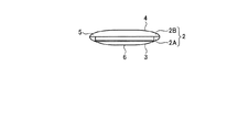
携帯電子機器1は、無線通信機能を備えた携帯電話機である。携帯電子機器1は、筐体2を有し、この筐体2の内部及び表面に各部が配置されている。筐体2は、図1から図4に示すように、箱型形状であり、第1筐体2Aと、第2筐体2Bとを貼り合わせた構造である。第1筐体2Aと第2筐体2Bとは、厚みが薄い板形状であり、夫々の面積が最も広い面同士が向かい合う向きで貼り合わせられている。また、第1筐体2Aと第2筐体2Bとの面積が最も広い面は、同一面積である。また、筐体2(第1筐体2Aと第2筐体2Bと)は、透明な材料で作製されている。ここで、透明な材料とは、光を透過する材料、例えばアクリル樹脂(PMMA)、ポリカードネート(PC)である。また、第1筐体2Aと第2筐体2Bとは、接着剤等で接合されており、接合面は、透明となっている。   The mobile electronic device 1 is a mobile phone having a wireless communication function. The portable electronic device 1 has a housing 2, and each part is disposed inside and on the surface of the housing 2. As shown in FIGS. 1 to 4, the housing 2 has a box shape and has a structure in which the first housing 2 </ b> A and the second housing 2 </ b> B are bonded together. 1st housing | casing 2A and 2nd housing | casing 2B are thin plate shape, and are bonded together in the direction where the surface where each area is the widest faces each other. Further, the surfaces having the largest areas of the first casing 2A and the second casing 2B have the same area. The housing 2 (the first housing 2A and the second housing 2B) is made of a transparent material. Here, the transparent material is a material that transmits light, such as acrylic resin (PMMA) or polycardnate (PC). The first housing 2A and the second housing 2B are joined with an adhesive or the like, and the joining surface is transparent.

筐体2は、外面が、表面(第1主面)3と、表面3に対向する(反対側の面である)裏面4(第2主面)と、表面3と裏面4との間の側面5とで構成されている。なお、第1筐体2Aの面積が最も広い面が表面3となり、第2筐体2Bの面積が最も広い面が裏面4となる。また、側面5は、表面3と裏面4の外縁であり、表面3及び裏面4に平行な方向、つまり図3または図4に示す方向から筐体2を見た場合に見える面である。この筐体2は、中心から端部に向かうにしたがって表面3と裏面4との間隔が短くなる形状である。つまり、筐体2は、図3及び図4 に示すように、側面5の断面が曲面となる形状である。   The housing 2 has an outer surface between a front surface (first main surface) 3, a back surface 4 (second main surface) opposite to the front surface 3 (an opposite surface), and between the front surface 3 and the back surface 4. It is comprised by the side surface 5. The surface with the largest area of the first housing 2A is the front surface 3, and the surface with the largest area of the second housing 2B is the back surface 4. The side surface 5 is an outer edge of the front surface 3 and the back surface 4, and is a surface that can be seen when the housing 2 is viewed from a direction parallel to the front surface 3 and the back surface 4, that is, the direction shown in FIG. The housing 2 has a shape in which the distance between the front surface 3 and the back surface 4 is shortened from the center toward the end. That is, the housing 2 has a shape in which the cross section of the side surface 5 is a curved surface, as shown in FIGS.

図1に示すように、筐体2(第1筐体2A)の表面3には、シート部6が設けられている。なお、シート部6は、表面3の長手方向において、中央よりも下側(標準的に使用した場合に下側となる向き)にオフセットして配置されている。つまり、シート部6は、表面3のうち下側にずれて配置されている。また、シート部6は、短手方向は、略全面に配置されている。このシート部6は、不透明な材料で作製されている。また、シート部6は、可撓性を有し、押されることで変形する。   As shown in FIG. 1, the sheet | seat part 6 is provided in the surface 3 of the housing | casing 2 (1st housing | casing 2A). In addition, the sheet part 6 is arranged offset in the longitudinal direction of the surface 3 below the center (the direction which is the lower side when used normally). In other words, the sheet portion 6 is arranged so as to be shifted to the lower side of the surface 3. Moreover, the sheet | seat part 6 is arrange | positioned in the transversal direction in the substantially whole surface. The sheet portion 6 is made of an opaque material. Further, the sheet portion 6 has flexibility and is deformed when pressed.

また、シート部6には、数字キー12、方向及び決定キー13、マイク15、カメラ36が設けられている。数字キー12は、電話番号入力時に数字を入力したり、メール作成時等に文字を入力したりするためのキーであり、シート部6の中央に配置されている。なお、数字キー12は、表面がシート部6に覆われている。方向及び決定キー13は、表示部32に表示されるメニューの選択及び決定や画面のスクロール等を容易に実行するためのキーであり、シート部6の数字キー12よりも上側に配置されている。また、マイク15は、携帯電子機器1の通話時に音声を受け取る部分であり、シート部6の下側で、短手方向の一方の端部(図中左側)に配置されている。さらに、カメラ36は、シート部6の下側で、短手方向の他方の端部(図中右側)に撮影窓が配置されている。さらに、筐体2の表面3の上側には、携帯電子機器1の通話時に音声を発するレシーバ16が設けられている。   The sheet unit 6 is provided with a numeric key 12, a direction / decision key 13, a microphone 15, and a camera 36. The number key 12 is a key for inputting a number when inputting a telephone number or inputting a character when creating a mail or the like, and is arranged at the center of the sheet portion 6. The number key 12 has a surface covered with the sheet portion 6. The direction and determination key 13 is a key for easily executing selection and determination of a menu displayed on the display unit 32, scrolling of the screen, and the like, and is disposed above the numeric key 12 of the sheet unit 6. . In addition, the microphone 15 is a part that receives voice during a call of the mobile electronic device 1, and is disposed on one end (left side in the drawing) in the short side direction below the seat unit 6. Further, the camera 36 is provided with a photographing window at the other end (right side in the drawing) in the short side direction below the seat portion 6. Furthermore, a receiver 16 that emits a sound during a call of the portable electronic device 1 is provided above the surface 3 of the housing 2.

次に、図5に示すように、筐体2の内部には、操作基板7と、回路基板8と、タッチパネル14、アンテナ26aと、表示部32と、バッテリ34と、が配置されている。操作基板7は、数字キー12と、方向及び決定キー13とに対面して配置された基板であり、数字キー12と、方向及び決定キー13に入力された操作を検出する検出回路や、検出した入力を後述する主制御部22に送る回路が設けられている。   Next, as shown in FIG. 5, the operation board 7, the circuit board 8, the touch panel 14, the antenna 26 a, the display unit 32, and the battery 34 are arranged inside the housing 2. The operation board 7 is a board arranged to face the numeric key 12 and the direction / decision key 13, a detection circuit for detecting an operation input to the numeric key 12, the direction / decision key 13, A circuit is provided for sending the input to the main control unit 22 described later.

回路基板8は、後述する主制御部22、記憶部24等の機能を持つ電子部品、例えばCPU、メモリ等が設置されている基板であり、操作基板7よりも裏面4側に配置されている。回路基板8は、筐体2の厚み方向に積層された2枚の基板で構成され、裏面4側に配置されている基板が表面3側の基板よりも面積が大きい基板である。また、回路基板8は、表面3に平行な面上において、数字キー12と、方向及び決定キー13が配置されている領域であり、シート部6が配置されている領域内に配置されている。また、回路基板8は、方向及び決定キー13側の一部に、厚みのある回路部材が設けられている。つまり、回路基板8は、方向及び決定キー13側の一部が、他の部分、つまり、マイク15側の部分よりも厚い形状となっている。   The circuit board 8 is a board on which electronic components having functions such as a main control unit 22 and a storage unit 24 described later, such as a CPU and a memory, are installed, and is arranged on the back surface 4 side with respect to the operation board 7. . The circuit board 8 is composed of two boards stacked in the thickness direction of the housing 2, and the board arranged on the back surface 4 side has a larger area than the board on the front surface 3 side. The circuit board 8 is an area in which the numeric key 12 and the direction / decision key 13 are arranged on a plane parallel to the surface 3, and is arranged in the area in which the sheet portion 6 is arranged. . Further, the circuit board 8 is provided with a thick circuit member at a part on the direction and determination key 13 side. That is, the circuit board 8 has a shape in which a part on the direction and determination key 13 side is thicker than the other part, that is, a part on the microphone 15 side.

次に、アンテナ26aは、筐体2の長手方向において、下側端部近傍に配置されている。具体的には、アンテナ26aは、筐体2の長手方向において、マイク15が配置されている側の端部、つまり、レシーバ16から離れている側の端部に短手方向に伸びて配置されている。また、アンテナ26aは、筐体2の厚み方向において、操作基板7と、回路基板8との間に配置されている。また、アンテナ26aは、表面3に平行な面上において、シート部6が配置されている領域内に配置されている。   Next, the antenna 26 a is disposed in the vicinity of the lower end in the longitudinal direction of the housing 2. Specifically, the antenna 26 a is arranged to extend in the short direction at the end portion on the side where the microphone 15 is arranged in the longitudinal direction of the housing 2, that is, the end portion on the side away from the receiver 16. ing. The antenna 26 a is disposed between the operation board 7 and the circuit board 8 in the thickness direction of the housing 2. The antenna 26 a is disposed in a region where the sheet portion 6 is disposed on a plane parallel to the surface 3.

バッテリ34は、操作基板7の裏面4側で回路基板8の表面3側、つまり、操作基板7と回路基板8との間に挟まれて配置されている。バッテリ34は、回路基板8のうち厚みが薄い領域と対面している。また、バッテリ34は、筐体2の長手方向において、アンテナ26aよりも上側に配置されている。   The battery 34 is disposed on the back surface 4 side of the operation board 7 and on the front surface 3 side of the circuit board 8, that is, sandwiched between the operation board 7 and the circuit board 8. The battery 34 faces a region of the circuit board 8 where the thickness is thin. Further, the battery 34 is disposed above the antenna 26 a in the longitudinal direction of the housing 2.

表示部32は、筐体2の回路基板8よりも裏面4側に配置されている。また、図1、図2及び図5に示すように、表示部32は、筐体2の長手方向、短手方向の両方向において、裏面4の大部分の領域に配置された板状の部材である。   The display unit 32 is arranged on the back surface 4 side of the circuit board 8 of the housing 2. In addition, as shown in FIGS. 1, 2, and 5, the display unit 32 is a plate-like member that is disposed in a large area of the back surface 4 in both the longitudinal direction and the short direction of the housing 2. is there.

表示部32は、所定の画像として、携帯電子機器1が受信を待機している状態のときに待ち受け画像を表示したり、携帯電子機器1の操作を補助するために用いられるメニュー画像を表示したりする。表示部32は、例えば、透明液晶モニター等の透明な表示装置であり、反対側が透けて見える。つまり、表示部32は、筐体2の外部から入射した光を通過させ筐体2の外部に射出することが可能となる。表示部32は、透明な表示装置であるため、表示している画像を表面3側、裏面4側の両方から視認することができる。これにより、携帯電子機器1は、表示部32の表面3側の面のうち、シート部6に覆われていない領域を、第1表示面42として用い、表示部32の裏面4側の面の全面を第2表示面44として用いる。つまり、携帯電子機器1は、表面3側から視認可能な第1表示面42と、裏面4側から視認可能な第2表示面44に画像を表示させ、表示部32として使用する。   The display unit 32 displays a standby image as a predetermined image when the portable electronic device 1 is waiting for reception, or a menu image used to assist the operation of the portable electronic device 1. Or The display unit 32 is a transparent display device such as a transparent liquid crystal monitor, and the opposite side can be seen through. That is, the display unit 32 can pass light incident from the outside of the housing 2 and emit the light to the outside of the housing 2. Since the display unit 32 is a transparent display device, the displayed image can be viewed from both the front surface 3 side and the back surface 4 side. Thereby, the portable electronic device 1 uses the area | region which is not covered with the sheet | seat part 6 among the surfaces by the side of the surface 3 of the display part 32 as the 1st display surface 42, and uses the area | region on the back surface 4 side of the display part 32. The entire surface is used as the second display surface 44. That is, the portable electronic device 1 displays an image on the first display surface 42 visible from the front surface 3 side and the second display surface 44 visible from the back surface 4 side, and uses it as the display unit 32.

なお、表示部32のうち、第1表示面42かつ第2表示面44となる領域は、厚み方向に積層されている部材が基本的に透明部材となる。従って、第1表示面42かつ第2表示面44となる領域は、筐体2の外側から見た場合反対側が見える、つまり、透けている状態となる。また、表示部32のうち、第2表示面44のみとなる領域は、表面3側に回路基板8等が配置されている。このため、表示部32を透明に維持すると、裏面4側からは、回路基板8が見える。   In the display unit 32, in the region that becomes the first display surface 42 and the second display surface 44, the members stacked in the thickness direction are basically transparent members. Accordingly, the regions that become the first display surface 42 and the second display surface 44 are seen from the opposite side when viewed from the outside of the housing 2, that is, are transparent. Further, in the area of the display unit 32 that is only the second display surface 44, the circuit board 8 and the like are arranged on the surface 3 side. For this reason, if the display part 32 is maintained transparent, the circuit board 8 can be seen from the back surface 4 side.

タッチパネル14は、表示部32の裏面4側の面に配置されている。タッチパネル14は、裏面4側から入力されるユーザの操作を検出する検出部であり、タッチパネル14のどの部分が指定されているかを検出する。なお、タッチパネル14は、表示部32と対面している領域が透明である。   The touch panel 14 is disposed on the surface on the back surface 4 side of the display unit 32. The touch panel 14 is a detection unit that detects a user operation input from the back surface 4 side, and detects which part of the touch panel 14 is designated. In the touch panel 14, the area facing the display unit 32 is transparent.

次に、携帯電子機器1の機能と制御部との関係を説明する。図6は、図1に示す携帯電子機器の機能の概略構成を示すブロック図である。図6に示すように携帯電子機器1は、主制御部22と、記憶部24と、通信部26と、操作部28と、音声処理部30と、表示部32と、表示制御部33と、バッテリ34と、カメラ36と、GPS通信部37と、地磁気センサ38と、を有する。   Next, the relationship between the function of the portable electronic device 1 and the control unit will be described. FIG. 6 is a block diagram showing a schematic configuration of functions of the portable electronic device shown in FIG. As shown in FIG. 6, the mobile electronic device 1 includes a main control unit 22, a storage unit 24, a communication unit 26, an operation unit 28, an audio processing unit 30, a display unit 32, a display control unit 33, A battery 34, a camera 36, a GPS communication unit 37, and a geomagnetic sensor 38 are included.

主制御部22は、携帯電子機器1の全体的な動作を統括的に制御する処理部、例えばCPU(Central Processing Unit)である。すなわち、携帯電子機器1の各種の処理が、操作部28の操作や携帯電子機器1の記憶部24に保存されるソフトウェアに応じて適切な手順で実行されるように、通信部26、表示部32等の動作を制御する。主制御部22は、記憶部24に保存されているプログラム(例えば、オペレーティングシステムのプログラム、アプリケーションのプログラム等)に基づいて処理を実行する。   The main control unit 22 is a processing unit that centrally controls the overall operation of the mobile electronic device 1, for example, a CPU (Central Processing Unit). That is, the communication unit 26, the display unit, and the like so that various types of processing of the portable electronic device 1 are executed in an appropriate procedure according to the operation of the operation unit 28 and the software stored in the storage unit 24 of the portable electronic device 1. 32 and the like are controlled. The main control unit 22 executes processing based on a program (for example, an operating system program, an application program, etc.) stored in the storage unit 24.

記憶部24には、主制御部22での処理に利用されるソフトウェアやデータ、具体的には、計器プログラム60と、計測プログラム62と、ナビゲーションプログラム64と、計器画像フォルダ66とが保存されている。ここで、計器プログラム60は、表示部32に計器を表示させるアプリケーションのプログラムである。また、計測プログラム62は、対象物との距離を計測(計算)する、または、対象物の大きさ、または対象物までの距離を計測(計算)するアプリケーションのプログラムである。ナビゲーションプログラム64は、ユーザに案内情報を通知するアプリケーションのプログラムである。また、計器画像フォルダ66とは、計器プログラム60の実行時に表示させる複数の計器を有する画像フォルダである。なお、計器プログラム60、計測プログラム62、ナビゲーションプログラム64を処理して実行するアプリケーションについては、後ほど説明する。   The storage unit 24 stores software and data used for processing in the main control unit 22, specifically, an instrument program 60, a measurement program 62, a navigation program 64, and an instrument image folder 66. Yes. Here, the instrument program 60 is an application program that causes the display unit 32 to display the instrument. The measurement program 62 is an application program for measuring (calculating) the distance to the object, or measuring (calculating) the size of the object or the distance to the object. The navigation program 64 is an application program that notifies the user of guidance information. The instrument image folder 66 is an image folder having a plurality of instruments to be displayed when the instrument program 60 is executed. An application that processes and executes the instrument program 60, the measurement program 62, and the navigation program 64 will be described later.

また、記憶部24には、表示部32に表示させる画像を制御するプログラムや、メールの送受信を実行するためのプログラムも保存されている。さらに、記憶部24には、プログラム以外の各種データとしては、計器画像フォルダ66以外にも、例えば、記憶部24には、各種設定条件や、ナビゲーションアプリで使用する地図情報や、アドレス帳や、文字変換に用いる辞書データや、カメラ(読取部)36で撮影した画像データ等が保存されている。   The storage unit 24 also stores a program for controlling an image displayed on the display unit 32 and a program for executing transmission / reception of mail. Further, in the storage unit 24, as various data other than the program, in addition to the instrument image folder 66, for example, in the storage unit 24, various setting conditions, map information used in the navigation application, address book, Dictionary data used for character conversion, image data taken by the camera (reading unit) 36, and the like are stored.

通信部26は、アンテナ26aを介して、基地局によって割り当てられるチャネルを介し、基地局との間でCDMA方式などによる無線信号回線を確立し、基地局との間で電話通信及び情報通信を行う。   The communication unit 26 establishes a radio signal line by a CDMA system or the like with the base station via a channel assigned by the base station via the antenna 26a, and performs telephone communication and information communication with the base station. .

操作部28は、例えば、電源キー、通話キー、数字キー、文字キー、方向キー、決定キー、発信キーなど、各種の機能が割り当てられた数字キー12、方向及び決定キー13、タッチパネル14とで構成される。操作部28は、これらのキーまたはタッチパネル14がユーザの操作により入力されると、その操作内容を主制御部22へ入力する。   The operation unit 28 includes, for example, a number key 12 to which various functions are assigned such as a power key, a call key, a number key, a character key, a direction key, a determination key, and a call key, a direction and determination key 13, and a touch panel 14. Composed. When these keys or the touch panel 14 are input by a user operation, the operation unit 28 inputs the operation content to the main control unit 22.

音声処理部30は、マイク15に入力される音声信号やレシーバ16から出力される音声信号の処理を実行する。   The audio processing unit 30 executes processing of an audio signal input to the microphone 15 and an audio signal output from the receiver 16.

表示部32は、上述したように、透明の表示装置であり、主制御部22から表示制御部33を介して供給される映像データに応じた映像、画像データに応じた画像を表示装置に表示させる。   As described above, the display unit 32 is a transparent display device, and displays a video corresponding to video data supplied from the main control unit 22 via the display control unit 33 and an image corresponding to the image data on the display device. Let

バッテリ34は、主制御部22等、携帯電子機器1の各部に電力を供給する電力源である。カメラ36は、表面3と対面している撮影領域(一定角度の視野角に含まれる領域)の画像を取得する撮像機構である。カメラ36は、撮影した画像を主制御部22に送る。   The battery 34 is a power source that supplies power to each unit of the portable electronic device 1 such as the main control unit 22. The camera 36 is an imaging mechanism that acquires an image of a shooting area facing the surface 3 (an area included in a certain viewing angle). The camera 36 sends the captured image to the main control unit 22.

GPS通信部37は、GPS(Global Positioning System、全地球測位システム)衛星から発信されるGPS信号を受信する通信部である。また、GPS通信部37は、受信したGPS信号から携帯電子機器1の緯度経度を算出し、算出した緯度経度の情報を主制御部22に送る。主制御部22は、GPS通信部37から送られる情報により、携帯電子機器1の位置を検出することができる。   The GPS communication unit 37 is a communication unit that receives a GPS signal transmitted from a GPS (Global Positioning System) satellite. In addition, the GPS communication unit 37 calculates the latitude and longitude of the mobile electronic device 1 from the received GPS signal, and sends the calculated latitude and longitude information to the main control unit 22. The main control unit 22 can detect the position of the portable electronic device 1 based on information sent from the GPS communication unit 37.

地磁気センサ38は、互いに直交する3つの方向における地磁気の向きを検出する検出器である。ここで、地磁気を検出する検出器としては、ホール素子、MR素子、MI素子、フラックスゲート素子等を用いることができる。地磁気センサ38は、検出した3つの方向における地磁気の向きの検出結果を主制御部22に送る。主制御部22は、地磁気センサ38の検出結果により、携帯電子機器1の向き(方角)を検出することができる。   The geomagnetic sensor 38 is a detector that detects the direction of geomagnetism in three directions orthogonal to each other. Here, as a detector for detecting geomagnetism, a Hall element, MR element, MI element, fluxgate element, or the like can be used. The geomagnetic sensor 38 sends the detection result of the direction of geomagnetism in the detected three directions to the main control unit 22. The main control unit 22 can detect the direction (direction) of the portable electronic device 1 based on the detection result of the geomagnetic sensor 38.

次に、図7−1及び図7−2を用いて、携帯電子機器1の動作、具体的には、計器プログラム60を実行する場合の動作について説明する。ここで、図7−1及び図7−2は、それぞれ携帯電子機器の動作を説明するための説明図である。なお、図7−1及び図7−2は、筺体2の表面3がユーザに向いており、第1表示面42に画像を表示させる場合である。   Next, the operation of the mobile electronic device 1, specifically, the operation when the instrument program 60 is executed will be described with reference to FIGS. Here, FIGS. 7A and 7B are explanatory diagrams for explaining the operation of the portable electronic device. FIGS. 7A and 7B illustrate a case where the surface 3 of the housing 2 faces the user and an image is displayed on the first display surface 42.

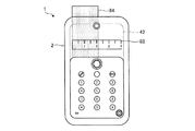
まず、携帯電子機器1は、ユーザにより計器を表示させるアプリケーションの起動指示が入力されたら、記憶部24に記憶されている計器プログラム60を主制御部22で処理し、該当するアプリケーションを起動させる。主制御部22は、アプリケーションが起動されたら、計器画像フォルダ66から画像、本実施形態では物差し(長さを計測するための計器)の画像を読み出し、表示部32の第1表示面42に表示させる。具体的には、図7−1に示すように、携帯電子機器1の表示部32の第1表示面42に、物差しである計器82を表示させる。   First, when an instruction for starting an application for displaying an instrument is input by the user, the portable electronic device 1 causes the main control unit 22 to process the instrument program 60 stored in the storage unit 24 to activate the corresponding application. When the application is started, the main control unit 22 reads out an image from the instrument image folder 66, in this embodiment, an image of a ruler (an instrument for measuring the length), and displays it on the first display surface 42 of the display unit 32. Let Specifically, as shown in FIG. 7A, an instrument 82 that is a ruler is displayed on the first display surface 42 of the display unit 32 of the portable electronic device 1.

ここで、第1表示面42は、透明な表示装置であるため、表面3側から裏面4側が透けて見える。このため、図7−1に示すように、筺体2の裏面4側の第1表示面42に対応する領域に測定対象84が密着する位置に、携帯電子機器1と測定対象84とを相対的に移動させることで、測定対象84に、計器82を重ねることができる。これにより、測定対象84の長さを計器82により計測することができる。なお、計器82は、筐体2の裏面4に密着している測定対象84の長さに対応した間隔で目盛りを表示させている。また、本実施形態では、測定対象84の測定している方向の長さは、約2cm(2cmを超える長さ)となる。   Here, since the first display surface 42 is a transparent display device, the rear surface 4 side can be seen through from the front surface 3 side. For this reason, as shown in FIG. 7A, the portable electronic device 1 and the measurement target 84 are relatively positioned at a position where the measurement target 84 is in close contact with the region corresponding to the first display surface 42 on the back surface 4 side of the housing 2. The instrument 82 can be overlaid on the measurement object 84 by moving the measurement object to. Thereby, the length of the measuring object 84 can be measured by the instrument 82. The instrument 82 displays scales at intervals corresponding to the length of the measurement object 84 that is in close contact with the back surface 4 of the housing 2. In the present embodiment, the length of the measuring object 84 in the measuring direction is about 2 cm (length exceeding 2 cm).

携帯電子機器1は、第1表示面42の後ろが透けて見える構成とし、さらに、第1表示面42に計器82を表示させることで、測定対象84の上に計器82を重ねた状態で測定することができる。これにより、表示部32の上に測定対象84を載せなくても測定ができるため、測定対象84が動かせない物体であっても、計器82を重ねることができ、種々の物体を測定対象とすることができる。   The portable electronic device 1 is configured such that the back of the first display surface 42 can be seen through, and the instrument 82 is displayed on the first display surface 42, so that the instrument 82 is superimposed on the measurement object 84. can do. Accordingly, since the measurement can be performed without placing the measurement object 84 on the display unit 32, the instrument 82 can be overlapped even if the measurement object 84 is an object that cannot be moved, and various objects are measured. be able to.

次に、主制御部22は、計器を表示させるアプリケーションにより、ユーザが入力した長さを比較対象として表示させることができる。また、図7−1に示す測定対象84の測定結果を比較対象として記憶させることもできる。ここで、比較対象を記憶させる方法としては、ユーザが測定した値を入力する方法がある。また、図7−1に示すような計測時に、第1表示面42にカーソルを表示させ、ユーザにより方向キーでカーソルを移動させ画面上で始点と終点を指定させ、その指定した始点と終点との距離を長さとして検出してもよい。なお、始点は、計器82の基点、つまり0cm地点とし、終点のみを指定するようにしてもよい。   Next, the main control unit 22 can display the length input by the user as a comparison target by an application for displaying the instrument. Moreover, the measurement result of the measurement object 84 shown in FIG. 7-1 can also be stored as a comparison object. Here, as a method of storing a comparison target, there is a method of inputting a value measured by a user. Further, at the time of measurement as shown in FIG. 7A, the cursor is displayed on the first display surface 42, the cursor is moved by the user with the direction key, the start point and end point are designated on the screen, and the designated start point and end point are specified. May be detected as the length. The starting point may be the base point of the instrument 82, that is, the 0 cm point, and only the end point may be designated.

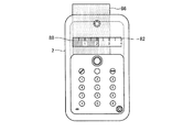
ここで、図7−2は、測定対象を測定中に比較対象を表示させた場合を示している。まず、携帯電子機器1は、測定対象86を計測するために、筺体2の裏面4側の第1表示面42に対応する領域に測定対象86が密着する位置に、携帯電子機器1と測定対象86とを相対的に移動させ、測定対象86と第1表示面42とを重ねる。ここで、携帯電子機器1は、図7−2に示すように、第1表示面42に、計器82に加え、比較対象88も表示させている。ここで、比較対象88は、記憶されている長さ分のバーであり、計器82の画像に重ねて表示されている。このように、比較対象88を表示させることで、ユーザは、比較対象88と測定対象86との大きさの違いを直感的に知ることができる。   Here, FIG. 7-2 illustrates a case where the comparison target is displayed during measurement. First, in order to measure the measuring object 86, the portable electronic device 1 and the measuring object 86 are in a position where the measuring object 86 is in close contact with the region corresponding to the first display surface 42 on the back surface 4 side of the housing 2. 86 is moved relatively, and the measuring object 86 and the first display surface 42 are overlapped. Here, as shown in FIG. 7B, the portable electronic device 1 displays a comparison target 88 in addition to the instrument 82 on the first display surface 42. Here, the comparison target 88 is a bar corresponding to the stored length, and is displayed so as to overlap the image of the instrument 82. In this way, by displaying the comparison target 88, the user can intuitively know the difference in size between the comparison target 88 and the measurement target 86.

ここで、図7−1及び図7−2では、計器として物差しを用いたが、計器はこれに限定されない。以下、図8−1及び図8−2を用いて、計器として分度器を用いる場合を説明する。ここで、図8−1及び図8−2は、それぞれ携帯電子機器の動作を説明するための説明図である。   Here, in FIG. 7A and FIG. 7B, the ruler is used as the instrument, but the instrument is not limited to this. Hereinafter, the case where a protractor is used as an instrument is demonstrated using FIGS. 8-1 and 8-2. Here, FIGS. 8A and 8B are explanatory diagrams for explaining the operation of the mobile electronic device.

本実施形態の主制御部22は、アプリケーションが起動されたら、計器画像フォルダ66から画像、本実施形態では分度器(角度を計測するための計器)を読み出し、表示部32の第1表示面42に表示させる。具体的には、図8−1に示すように、携帯電子機器1の表示部32の第1表示面42に、分度器である計器92を表示させる。   When the application is activated, the main control unit 22 of the present embodiment reads an image from the instrument image folder 66, in this embodiment, a protractor (an instrument for measuring an angle), and displays it on the first display surface 42 of the display unit 32. Display. Specifically, as shown in FIG. 8A, a meter 92 that is a protractor is displayed on the first display surface 42 of the display unit 32 of the portable electronic device 1.

このように計器92を表示させ、上述と同様に携帯電子機器1と測定対象94とを相対的に移動させることで、測定対象94に、計器92を重ねることができる。これにより、測定対象94の角度(なす角)を計器92により計測することができる。   In this way, the instrument 92 is displayed, and the instrument 92 can be superimposed on the measurement target 94 by relatively moving the portable electronic device 1 and the measurement target 94 in the same manner as described above. Thereby, the angle (angle formed) of the measuring object 94 can be measured by the meter 92.

また、本実施形態も主制御部は、計器を表示させるアプリケーションにより、ユーザが入力した長さを比較対象として表示させることができる。また、図8−1に示す測定対象94の測定結果を比較対象として記憶させることもできる。ここで、比較対象を記憶させる方法は上述の長さの場合と同様である。   In addition, in this embodiment, the main control unit can display the length input by the user as a comparison target by an application for displaying the instrument. Further, the measurement result of the measurement object 94 shown in FIG. 8-1 can be stored as a comparison object. Here, the method for storing the comparison target is the same as that for the above-described length.

また、携帯電子機器1は、分度器を表示させる場合も、図8−2に示すように、測定対象96の測定時に第1表示面42に、計器92に加え、記憶したまたは設定された比較対象98も表示させることができる。ここで、比較対象98は、記憶されている角度分のバーであり、計器92の画像に重ねて表示されている。   Further, in the case where the portable electronic device 1 displays a protractor, as shown in FIG. 8B, in addition to the instrument 92, the comparison object stored or set on the first display surface 42 when the measurement object 96 is measured. 98 can also be displayed. Here, the comparison object 98 is a bar corresponding to the stored angle, and is displayed so as to be superimposed on the image of the instrument 92.

このように、計器として分度器を用いる場合も物差しの場合と同様に種々の対象物の角度を計測することが可能となる。また、比較対象を表示させることで、直感的に角度を比較することができる。   Thus, even when a protractor is used as a meter, it is possible to measure angles of various objects as in the case of a ruler. Further, the angle can be intuitively compared by displaying the comparison target.

なお、表示部32に表示させる計器は、物差し、分度器に限定されず、長さ、角度等の形状の測定に用いる種々の計器を表示させることができる。また、ユーザは、必要に応じて、表示させる計器を計器フォルダの中から選択すればよい。   In addition, the instrument displayed on the display part 32 is not limited to a scale and a protractor, but can display various instruments used for measuring shapes such as length and angle. In addition, the user may select an instrument to be displayed from the instrument folder as necessary.

また、携帯電子機器1は、通信部26を介して外部との通信を行い、計器の画像データを取得するようにしてもよい。このように、外部から計器の画像データを取得することで、種々の計器の画像を取得することが可能となる。また、記憶部24の計器画像フォルダ66に記憶させる画像データを少なくすることができる。   Further, the portable electronic device 1 may communicate with the outside via the communication unit 26 to acquire the image data of the instrument. As described above, by acquiring the image data of the instrument from the outside, it is possible to acquire images of various instruments. Further, the image data stored in the instrument image folder 66 of the storage unit 24 can be reduced.

次に、図9−1及び図9−2を用いて、携帯電子機器1の動作、具体的には、計測プログラム62を実行する場合の動作について説明する。ここで、図9−1及び図9−2は、それぞれ携帯電子機器の動作を説明するための説明図である。なお、図9−1は、筺体2の表面3がユーザに向いており、第1表示面42に画像を表示させる場合である。図9−2は、筺体2の裏面4がユーザに向いており、第2表示面44に画像を表示させる場合である。ここで、計測プログラム62を処理することで実行される、対象物の大きさ、または対象物までの距離を計測するアプリケーション(以下「計測アプリケーション」という。)は、対象物の大きさ、または、対象物までの距離の一方が既知の状態で、他方の未知の値を検出し、計測結果として出力する。   Next, the operation of the mobile electronic device 1, specifically, the operation when the measurement program 62 is executed will be described with reference to FIGS. Here, FIGS. 9A and 9B are explanatory diagrams for explaining the operation of the mobile electronic device. FIG. 9A is a case where the surface 3 of the housing 2 is facing the user and an image is displayed on the first display surface 42. FIG. 9-2 is a case where the back surface 4 of the housing 2 is facing the user and an image is displayed on the second display surface 44. Here, the application for measuring the size of the object or the distance to the object (hereinafter referred to as “measurement application”) executed by processing the measurement program 62 is the size of the object, or One of the distances to the object is known and the other unknown value is detected and output as a measurement result.

まず、携帯電子機器1は、ユーザにより計測アプリケーションの起動指示が入力されたら、記憶部24に記憶されている計測プログラム62を主制御部22で処理し、計測アプリケーションを起動させる。主制御部22は、計測アプリケーションが起動されたら、図9−1に示すように基準バー104を表示させる。   First, when an instruction to start a measurement application is input by the user, the portable electronic device 1 causes the main control unit 22 to process the measurement program 62 stored in the storage unit 24 to start the measurement application. When the measurement application is activated, the main control unit 22 displays the reference bar 104 as shown in FIG.

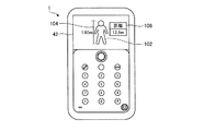
ユーザは、基準バー104が表示された状態の第1表示面42と対象物、本実施形態では、人物102とを重ねる。その後、ユーザは、第1表示面42に表示されている基準バー104の長さを人物102の長さと同じにする。携帯電子機器1の主制御部22は、ユーザによって入力される操作に基づいて、第1表示面42内における基準バー104の位置や長さを変化させる。   The user overlaps the first display surface 42 in a state where the reference bar 104 is displayed and the object, in this embodiment, the person 102. Thereafter, the user makes the length of the reference bar 104 displayed on the first display surface 42 the same as the length of the person 102. The main control unit 22 of the portable electronic device 1 changes the position and length of the reference bar 104 in the first display surface 42 based on an operation input by the user.

ユーザは、基準バー104の長さを人物102の長さと同じにしたら、既知の値を入力する。例えば、人物102の長さ(身長)が既知の場合は、人物102の長さ、本実施形態では1.65mを入力する。携帯電子機器1の主制御部22は、人物102の長さ、つまり、基準バー104の長さが入力されたら、第1表示面42に表示させている基準バー104の長さと、入力された長さの値に基づいて、人物102との距離を算出する。主制御部22は、算出した距離を項目106として第1表示面42に表示させる。   When the length of the reference bar 104 is the same as the length of the person 102, the user inputs a known value. For example, when the length (height) of the person 102 is known, the length of the person 102, 1.65 m in this embodiment, is input. When the length of the person 102, that is, the length of the reference bar 104 is input, the main control unit 22 of the portable electronic device 1 inputs the length of the reference bar 104 displayed on the first display surface 42. Based on the length value, the distance to the person 102 is calculated. The main control unit 22 displays the calculated distance on the first display surface 42 as the item 106.

なお、主制御部22は、人物102との距離が既知の場合は、距離を入力することで、入力された距離と第1表示面42に表示されている基準バー104の長さとの関係から、人物102の実際の長さを算出することもできる。なお、算出方法としては、三角法(三角測量で使用する計算方法)を用いることができる。   If the distance to the person 102 is known, the main control unit 22 inputs the distance, and the relationship between the input distance and the length of the reference bar 104 displayed on the first display surface 42 is obtained. The actual length of the person 102 can also be calculated. As a calculation method, trigonometry (calculation method used in triangulation) can be used.

携帯電子機器1は、対象物を第1表示面42に重ねても、第1表示面42を介して、対象物を確認することができる。これにより、第1表示面42に表示させている基準バー104と、対象物の画面上での大きさを合わせることができ、さらに、既知の対象物の大きさ、または、既知の対象物までの距離を入力することで、未知の対象物までの距離、または、未知の対象物の大きさを算出することができる。また、携帯電子機器1は、実際にすかして見える実物を対象として、計測を行うため、計測結果を直感的に理解することができる。   The portable electronic device 1 can confirm the object via the first display surface 42 even if the object is superimposed on the first display surface 42. Thereby, the reference bar 104 displayed on the first display surface 42 can be matched with the size of the object on the screen, and the size of the known object or even the known object can be adjusted. , The distance to the unknown object or the size of the unknown object can be calculated. Moreover, since the portable electronic device 1 performs the measurement on the actual object that looks faint, the measurement result can be intuitively understood.

ここで、上記実施形態では、第1表示面42に画像を表示させたが、第2表示面44に画像を表示させて、計測アプリケーションを実行してもよい。以下、図9−2を用いて、第2表示面44に画像を表示させる場合について説明する。ここで、携帯電子機器1は、図9−2に示すように、第2表示面44のうち第1表示面42かつ第2表示面44となる領域が第1表示領域110となり、第2表示面44のみとなる領域が第2表示領域112となる。なお、表示部32に画像を表示させていない場合、第1表示領域110は、透明で筐体2の反対側の景色が透けて見え、第2表示領域112は、回路基板8が見える。なお、主制御部22は、第1表示領域110の背景を透明(つまり透けて見える状態)とし、第2表示領域112の背景を不透明としている。   Here, in the above embodiment, an image is displayed on the first display surface 42. However, the measurement application may be executed by displaying an image on the second display surface 44. Hereinafter, a case where an image is displayed on the second display surface 44 will be described with reference to FIG. Here, in the mobile electronic device 1, as illustrated in FIG. 9B, the region that becomes the first display surface 42 and the second display surface 44 in the second display surface 44 becomes the first display region 110, and the second display surface 44. A region that is only the surface 44 is the second display region 112. When no image is displayed on the display unit 32, the first display area 110 is transparent and the scenery on the opposite side of the housing 2 can be seen through, and the circuit board 8 can be seen in the second display area 112. The main control unit 22 makes the background of the first display area 110 transparent (that is, shows through) and makes the background of the second display area 112 opaque.

まず、携帯電子機器1は、ユーザにより計測アプリケーションの起動指示が入力されたら、記憶部24に記憶されている計測プログラム62を主制御部22で処理し、計測アプリケーションを起動させる。主制御部22は、計測アプリケーションが起動されたら、図9−2に示すように第2表示面44に基準バー114を表示させる。   First, when an instruction to start a measurement application is input by the user, the portable electronic device 1 causes the main control unit 22 to process the measurement program 62 stored in the storage unit 24 to start the measurement application. When the measurement application is activated, the main control unit 22 displays the reference bar 114 on the second display surface 44 as shown in FIG. 9-2.

ユーザは、基準バー114が表示された状態の第2表示面44の第1表示領域110と人物102とを重ねる。その後、ユーザは、第2表示面44に表示されている基準バー114を第1表示領域110に移動させ、基準バー114の長さを人物102の長さと同じにする。携帯電子機器1の主制御部22は、ユーザによって入力される操作に基づいて、第2表示面44内における基準バー114の位置や長さを変化させる。なお、基準バー114は、予め第1表示領域110に表示させてもよい。また、主制御部22は、タッチパネル14に入力される操作をユーザの操作として検出する。   The user overlaps the first display area 110 of the second display surface 44 with the reference bar 114 displayed on the person 102. Thereafter, the user moves the reference bar 114 displayed on the second display surface 44 to the first display area 110 so that the length of the reference bar 114 is the same as the length of the person 102. The main control unit 22 of the portable electronic device 1 changes the position and length of the reference bar 114 in the second display surface 44 based on an operation input by the user. The reference bar 114 may be displayed in the first display area 110 in advance. Further, the main control unit 22 detects an operation input to the touch panel 14 as a user operation.

ユーザは、基準バー114の長さを人物102の長さと同じにしたら、既知の値を入力する。ここで、主制御部22は、第2表示領域112に、基準バー114の高さを表示させる項目116と、対象物までの距離を表示させる項目118と、数字ボタン119を表示させている。主制御部22は、ユーザによる数字ボタン119に対応する位置の押下をタッチパネル14で検出することで、数値の入力を検出する。主制御部22は、例えば、人物102の長さ(身長)が既知の場合は、人物102の長さとして1.65mが入力されたら、項目116に入力結果を表示させる。なお、基準高さを入力するか、距離を入力するかの、入力する項目の選択は、いずれの項目に対応する位置をユーザがタッチしたかを検出して判断すればよい。さらに、主制御部22は、第1表示面42に表示させている基準バー104の長さと、入力された長さの値に基づいて、人物102との距離を算出する。主制御部22は、算出した距離を項目118に表示させる。   When the length of the reference bar 114 is the same as the length of the person 102, the user inputs a known value. Here, the main control unit 22 displays, in the second display area 112, an item 116 for displaying the height of the reference bar 114, an item 118 for displaying the distance to the object, and a numeric button 119. The main control unit 22 detects an input of a numerical value by detecting, on the touch panel 14, a position pressed by the user corresponding to the numeric button 119. For example, when the length (height) of the person 102 is known, the main control unit 22 displays the input result in the item 116 when 1.65 m is input as the length of the person 102. Whether to input a reference height or a distance, and to select an item to be input may be determined by detecting whether the user has touched a position corresponding to which item. Further, the main control unit 22 calculates the distance from the person 102 based on the length of the reference bar 104 displayed on the first display surface 42 and the input length value. The main control unit 22 displays the calculated distance in the item 118.

このように、第2表示面44に画像を表示させる場合でも同様の処理で、対象物までの距離または対象物の大きさを算出し、表示させることができる。また、第2表示面44は、第1表示面42よりも表示面積が多いため、種々の情報を表示させることができる。また、ユーザは、タッチパネル14に操作を入力できるため、方向キー等の操作をすることなく、基準バー114の位置、大きさを調整することができる。これにより、直感的に操作を行うことが可能となる。   Thus, even when an image is displayed on the second display surface 44, the distance to the object or the size of the object can be calculated and displayed by the same processing. Further, since the second display surface 44 has a larger display area than the first display surface 42, various information can be displayed. Further, since the user can input an operation to the touch panel 14, the user can adjust the position and size of the reference bar 114 without operating a direction key or the like. This makes it possible to perform an intuitive operation.

また、図9−2では、計測アプリケーションの場合で説明したが、計器を表示させるアプリケーションを実行する場合も第2表示面44に画像を表示させるようにしてもよい。   9-2 has been described in the case of a measurement application, an image may be displayed on the second display surface 44 also when an application for displaying a meter is executed.

次に、図10、図11−1及び図11−2を用いて、携帯電子機器1の動作、具体的には、ナビゲーションプログラム64を実行する場合の動作について説明する。ここで、図10は、携帯電子機器の周囲の状況を説明するための説明図であり、図11−1及び図11−2は、それぞれ携帯電子機器の動作を説明するための説明図である。なお、図11−1は、筺体2の表面3がユーザに向いており、第1表示面42に画像を表示させる場合である。図11−2は、筺体2の裏面4がユーザに向いており、第2表示面44に画像を表示させる場合である。ここで、ナビゲーションプログラム64を処理することで実行される、ナビゲーションアプリケーションは、ユーザの現在位置、また、向いている方向を検出し、ユーザに周辺の状況を通知する。また、ナビゲーションアプリケーションは、設定された目的地への案内情報を通知することもできる。   Next, the operation of the mobile electronic device 1, specifically, the operation when the navigation program 64 is executed will be described with reference to FIGS. 10, 11-1, and 11-2. Here, FIG. 10 is an explanatory diagram for explaining the situation around the portable electronic device, and FIGS. 11A and 11B are explanatory diagrams for explaining the operation of the portable electronic device. . FIG. 11A is a case where the surface 3 of the housing 2 is facing the user and an image is displayed on the first display surface 42. FIG. 11B illustrates a case where the back surface 4 of the housing 2 is facing the user and an image is displayed on the second display surface 44. Here, the navigation application executed by processing the navigation program 64 detects the current position of the user and the direction in which the user is facing, and notifies the user of the surrounding situation. The navigation application can also notify the guide information to the set destination.

まず、図10に示すように、携帯電子機器1を持っているユーザ(人物131)は、向いている方向に建物132と、タワー134がある道136に立っている。携帯電子機器1は、この位置状態にいる場合に、ナビゲーションアプリケーションを起動させた場合として説明する。なお、建物132にはAビル、タワー134にはBタワー、道136にはC通りという名称が付けられている。   First, as shown in FIG. 10, the user (person 131) holding the portable electronic device 1 stands on a road 136 with a building 132 and a tower 134 in the facing direction. The portable electronic device 1 will be described as a case where the navigation application is activated in this position state. The building 132 is named A building, the tower 134 is named B tower, and the street 136 is named C street.

まず、携帯電子機器1は、ユーザによりナビゲーションアプリケーションの起動指示が入力されたら、記憶部24に記憶されているナビゲーションプログラム64を主制御部22で処理し、該当するアプリケーションを起動させる。主制御部22は、アプリケーションが起動されたら、GPS通信部37により携帯電子機器1の位置情報を取得し、さらに、地磁気センサ38で携帯電子機器1が向いている方角、水平面に対する角度を検出する。主制御部22は、携帯電子機器1は、位置と、向いている方向、角度を検出したら、該当する領域(自身がいる位置の周囲)の地図情報を取得する。なお地図情報は、記憶部24に記憶された地図情報を取得しても、通信部26を介して外部のデータベースから情報を取得してもよい。   First, when a navigation application activation instruction is input by the user, the portable electronic device 1 processes the navigation program 64 stored in the storage unit 24 by the main control unit 22 and activates the corresponding application. When the application is started, the main control unit 22 acquires the position information of the portable electronic device 1 by the GPS communication unit 37, and further detects the direction in which the portable electronic device 1 is facing and the angle with respect to the horizontal plane by the geomagnetic sensor 38. . When the mobile electronic device 1 detects the position, the direction in which the portable electronic device 1 is facing, and the angle, the main control unit 22 acquires map information of the corresponding region (around the position where the mobile electronic device 1 is). Note that the map information may be obtained from the map information stored in the storage unit 24 or may be obtained from an external database via the communication unit 26.

主制御部22は、地図情報を取得したら、位置と、向いている方向、角度に基づいて、第1表示面42に透けて見える景色、つまり、ユーザが第1表示面42を見たときに第1表示面42に重なって見える景色に含まれる建物、道を検出する。その後、主制御部22は、検出した第1表示面42内に見える建物、道の位置を算出し、該当する位置に、建物、道の情報(例えば、名称)を表示させる。具体的には、図11−1に示すように、建物132、タワー134、道136が第1表示面42に重なって見える場合 、主制御部22は、建物132に重なる位置に「Aビル」という文字情報142を表示させ、タワー134に重なる位置に「Bタワー」という文字情報144を表示させ、道136に重なる位置に「C通り」という文字情報146を表示させる。また、主制御部22は、ユーザが進むべき方向を矢印148で表示する。   When the main control unit 22 acquires the map information, based on the position, direction, and angle, the main control unit 22 can see through the first display surface 42, that is, when the user views the first display surface 42. A building and a road included in the scenery that is visible on the first display surface 42 are detected. Thereafter, the main control unit 22 calculates the position of the building and road that can be seen in the detected first display surface 42, and displays the information (for example, name) of the building and road at the corresponding position. Specifically, as shown in FIG. 11A, when the building 132, the tower 134, and the road 136 appear to overlap the first display surface 42, the main control unit 22 sets “A building” at a position overlapping the building 132. Character information 142 is displayed, character information 144 “B tower” is displayed at a position overlapping the tower 134, and character information 146 “C street” is displayed at a position overlapping the road 136. Further, the main control unit 22 displays the direction in which the user should proceed with an arrow 148.

携帯電子機器1は、第1表示面42に重なって見える背景にナビゲーションに関する情報を重ねて表示させることで、ユーザが直感的に理解しやすい情報を提供することができる。具体的には、実際の背景(風景、建物)にナビゲーションの情報を重ねて表示させることで、ユーザがナビゲーションの情報と実際の背景とを比較して、判断する必要がなくなる。つまり、地図や表示部に表示される情報と、実際の風景の両者を見比べて対応付けを行う必要がなく、第1表示面42のみを見ることで、対応付けを理解することができる。そのため、ユーザは、自分の周囲に関する情報や、移動すべき道をより簡単に理解することができる。   The portable electronic device 1 can provide information that is easy for the user to understand intuitively by displaying the navigation-related information superimposed on the background that appears to overlap the first display surface 42. Specifically, by displaying the navigation information superimposed on the actual background (landscape, building), it is not necessary for the user to compare and determine the navigation information and the actual background. In other words, it is not necessary to compare the information displayed on the map or the display unit with the actual landscape and perform the association, and the association can be understood by looking only at the first display surface 42. Therefore, the user can more easily understand the information about his / her surroundings and the road to be moved.

なお、上記実施形態では、道案内の情報と、周囲の情報の両方を表示させたが、表示させる情報は、目的に応じて切り替えればよい。   In the above embodiment, both the road guidance information and the surrounding information are displayed. However, the information to be displayed may be switched according to the purpose.

ここで、上記実施形態では、第1表示面42に画像を表示させたが、ナビゲーションアプリケーションを実行する場合も、第2表示面44に画像を表示させてもよい。以下、図11−2を用いて、第2表示面44に画像を表示させる場合について説明する。なお、本実施形態も、第1表示領域110の背景を透明(つまり透けて見える状態)とし、第2表示領域112の背景を不透明としている。   Here, in the above-described embodiment, an image is displayed on the first display surface 42, but an image may be displayed on the second display surface 44 even when a navigation application is executed. Hereinafter, the case where an image is displayed on the second display surface 44 will be described with reference to FIG. In this embodiment as well, the background of the first display area 110 is transparent (that is, it can be seen through), and the background of the second display area 112 is opaque.

携帯電子機器1は、ナビゲーションアプリケーションを起動させたら、GPS通信部37により携帯電子機器1の位置情報を取得し、さらに、地磁気センサ38で携帯電子機器1が向いている方角、水平面に対する角度を検出する。主制御部22は、携帯電子機器1は、位置と、向いている方向、角度を検出したら、該当領域の地図情報を取得する。主制御部22は、地図情報を取得したら、位置と、向いている方向、角度に基づいて、第2表示面44の第1表示領域110に透けて見える景色に含まれる建物、道を検出する。   When the navigation application is activated, the portable electronic device 1 acquires the position information of the portable electronic device 1 by the GPS communication unit 37, and further detects the direction in which the portable electronic device 1 is facing and the angle with respect to the horizontal plane by the geomagnetic sensor 38. To do. When the mobile electronic device 1 detects the position, the facing direction, and the angle, the main control unit 22 acquires the map information of the corresponding area. When the main control unit 22 acquires the map information, the main control unit 22 detects buildings and roads included in the scenery that can be seen through the first display area 110 of the second display surface 44 based on the position, the facing direction, and the angle. .

さらに、主制御部22は、検出した第1表示領域110内に見える建物、道の位置を算出し、該当する位置に、建物、道の情報(例えば、名称)を表示させる。具体的には、図11−2に示すように、建物132、タワー134、道136が第1表示面42に重なって見える場合、主制御部22は、「Aビル」という文字情報152、「Bタワー」という文字情報154、「C通り」という文字情報156を表示させる。ここで、文字情報152、文字情報154、文字情報156は、第2表示領域112に表示される。また、第2表示面44には、文字情報152と建物132に重なる位置とを結ぶ線、文字情報154とタワー134に重なる位置とを結ぶ線、文字情報156が道136に重なる位置を指すことを示す矢印が表示される。さらに、主制御部22は、ユーザが進むべき方向を示す「C通りを直進」という文字情報158を第2表示領域112に表示させる。   Furthermore, the main control unit 22 calculates the positions of buildings and roads that can be seen in the detected first display area 110, and displays information on the buildings and roads (for example, names) at the corresponding positions. Specifically, as shown in FIG. 11B, when the building 132, the tower 134, and the road 136 appear to overlap the first display surface 42, the main control unit 22 reads the character information 152 “ Character information 154 “B tower” and character information 156 “C street” are displayed. Here, the character information 152, the character information 154, and the character information 156 are displayed in the second display area 112. The second display surface 44 indicates a line connecting the character information 152 and the position overlapping the building 132, a line connecting the character information 154 and the position overlapping the tower 134, and a position where the character information 156 overlaps the road 136. An arrow indicating is displayed. Further, the main control unit 22 causes the second display area 112 to display character information 158 “straight ahead on C streets” indicating the direction in which the user should proceed.

このように、第2表示面44に画像を表示させる場合も、図11−1に示す場合と同様にナビゲーションアプリケーションを実行することができる。また、第2表示面44に画像を表示させる場合は、文字情報を第2表示領域112に表示させることで、第1表示領域110に透けて見える背景をより、明確に確認することができる。つまり、ナビゲーションアプリケーションで作成した情報は、第2表示領域に優先的に表示させることで、背景を見やすくしつつ、情報を取得することができる。これにより、取得した情報をより理解しやすくすることができる。また、上記実施形態では、背景の各部と、情報とを矢印や、線で対応付けたが、これには限定されず、番号を付して対応付けてもよい。   Thus, also when displaying an image on the 2nd display surface 44, a navigation application can be performed similarly to the case shown to FIGS. Further, when displaying an image on the second display surface 44, the character information is displayed on the second display area 112, so that the background seen through the first display area 110 can be confirmed more clearly. That is, the information created by the navigation application can be acquired while making the background easy to see by displaying the information preferentially in the second display area. Thereby, the acquired information can be made easier to understand. Moreover, in the said embodiment, although each part of the background and information were matched with the arrow and the line, it is not limited to this, You may attach | subject and attach a number.

なお、上記実施形態では、携帯電子機器を、計器を用いた計測、測量、ナビゲーションに用いた場合について説明したがこれに限定されない。携帯電子機器は、主制御部22により、第1表示面42または、第2表示面44の第1表示領域110に重なって見える物体(背景)との関係を、縮尺(長さ、大きさ)や、方位(方角)に基づいて処理するアプリケーションであれば種々のアプリケーションを用いることができる。いずれも、物体と表示部の画像とを重ねることができるため、表示部に表示される情報を直感的に理解しやすくすることができる。   In addition, although the said embodiment demonstrated the case where a portable electronic device was used for the measurement using a meter, surveying, and navigation, it is not limited to this. In the portable electronic device, the main control unit 22 reduces the scale (length and size) of the relationship with the object (background) that appears to overlap the first display area 110 of the first display surface 42 or the second display surface 44. In addition, various applications can be used as long as the application processes based on the azimuth (direction). In any case, since the object and the image of the display unit can be overlapped, the information displayed on the display unit can be easily understood intuitively.

ここで、携帯電子機器1は、本実施形態のように、操作基板7と、回路基板8と、アンテナ26aと、バッテリ34とは、数字キー12、方向及び決定キー13と表示部32との間に挟まれた領域、つまり、シート部6と表示部32との間に挟まれた領域に配置することが好ましい。これにより、携帯電子機器1を筐体2の表面3側から見た場合、操作基板7と、回路基板8と、アンテナ26aと、バッテリ34とは、本実施形態では、シート部6に隠れて見えない構成とすることができる。   Here, as in the present embodiment, the portable electronic device 1 includes the operation board 7, the circuit board 8, the antenna 26 a, and the battery 34, the number key 12, the direction and determination key 13, and the display unit 32. It is preferable to arrange in a region sandwiched between the sheet unit 6 and the display unit 32. Thereby, when the portable electronic device 1 is viewed from the front surface 3 side of the housing 2, the operation board 7, the circuit board 8, the antenna 26a, and the battery 34 are hidden by the seat portion 6 in this embodiment. It can be set as an invisible structure.

さらに、筐体2は、側面5を曲面形状とすることで、回路基板8を見ようとして側面5側から筐体2の内部を覗いても、回路基板8が見えない構造となっている。つまり、側面5を曲面形状とし、側面5から入射した光を屈折させることで、筐体2の側面5から入射した光が回路基板8に届かない構成となる。   Further, the housing 2 has a structure in which the circuit board 8 cannot be seen even if the inside of the housing 2 is looked into from the side surface 5 side when looking at the circuit board 8 by making the side surface 5 curved. That is, the side surface 5 has a curved shape, and the light incident from the side surface 5 is refracted so that the light incident from the side surface 5 of the housing 2 does not reach the circuit board 8.

さらに、携帯電子機器1は、筐体2の裏面4側に、表示部32を配置している。これにより、携帯電子機器1は、表示部32に画像を表示させることで、裏面4側からも回路基板8を見えないようにすることができる。   Furthermore, the mobile electronic device 1 has a display unit 32 disposed on the back surface 4 side of the housing 2. Thereby, the portable electronic device 1 can display the image on the display unit 32 so that the circuit board 8 cannot be seen from the back surface 4 side.

これにより、本実施形態の携帯電子機器1は、筐体2を透明としても、回路基板8等の電子部品を見えないようにすることができ、優れた美観とすることができる。さらに、数字キー12、方向及び決定キー13等の各種キーも配置できるため、操作をしやすくすることができる。   Thereby, even if the portable electronic device 1 of this embodiment makes the housing | casing 2 transparent, it can hide electronic components, such as the circuit board 8, and can make it the outstanding beauty | look. Furthermore, since various keys such as the numeric key 12, direction and determination key 13 can be arranged, the operation can be facilitated.

また、数字キー12、方向及び決定キー13が配置されている表面3側に第1表示面42を設けることで、第1表示面42に操作画面を表示させることができる。また、裏面4側により大きい第2表示面44を設けることで、大画面に画像を表示させることができる。また、表示部32を透明表示装置とすることで、1つの表示部32で第1表示面42、第2表示面44の両方に画像を表示させることができる。なお、表示面によって、表示させる画像を判定(選択)させることで、適切な画像を表示させることができる。つまり、主制御部22及び表示制御部33の制御により、使用されている表示面に適切な画像を表示させることができる。また、携帯電子機器1は、表面3に、数字キー12、方向及び決定キー13と、表示面積が小さい第1表示面42とを備え、裏面4に、タッチパネル14と、表示面積が大きい第2表示面44とを備える。これにより、携帯電子機器1の使用用途に応じて、表面3と裏面4とを使い分けることができる。例えば、メール等の数字、文字の入力が多くなる操作は、表面3で行い、画面の拡大や、選択が主の操作となる動画、画像の観賞、操作は、裏面4で行うようにすることができる。これにより、操作性を高くすることができる。   In addition, the operation screen can be displayed on the first display surface 42 by providing the first display surface 42 on the front surface 3 side where the numeric keys 12, the direction and the determination key 13 are arranged. Moreover, an image can be displayed on a large screen by providing a larger second display surface 44 on the back surface 4 side. In addition, by using the display unit 32 as a transparent display device, it is possible to display an image on both the first display surface 42 and the second display surface 44 with one display unit 32. An appropriate image can be displayed by determining (selecting) an image to be displayed on the display surface. In other words, an appropriate image can be displayed on the display surface used by the control of the main control unit 22 and the display control unit 33. Moreover, the portable electronic device 1 is provided with a numeric key 12, a direction and determination key 13, and a first display surface 42 having a small display area on the front surface 3, and a touch panel 14 on the back surface 4 and a second display area having a large display area. And a display surface 44. Thereby, according to the use application of the portable electronic device 1, the front surface 3 and the back surface 4 can be used properly. For example, operations such as e-mails that increase the number of characters and characters are performed on the front surface 3, and enlargement of the screen and video / image viewing and operations whose main operations are selection are performed on the back surface 4. Can do. Thereby, operativity can be made high.

また、筐体2の数字キー12、方向及び決定キー13等の物理キー(所定の位置に固定されており、タッチパネル14のように透明な板状部材ではないキー)が配置されている面に不透明のシート部6を設けることで、より確実に回路基板8を隠すことができる。このような効果を得ることができるため、シート部6は、不透明とすることが好ましいが、これに限定されず、半透明としてもよい。シート部6を半透明とすることで、回路基板8を見えにくくすることができる。シート部6を見えにくくすることで、美観も一定以上高くすることができる。また、シート部6は、本実施形態のように数字キー12の表面を覆うように配置することが好ましい。これにより、数字キー12の表面の外観を1枚のシート状にすることができ、美観に優れた形状とすることができる。また、キーと筺体2との間の隙間が露出しない構成となるため、防水性を高めることができ、筺体2の構造も簡単になる。   In addition, on the surface of the housing 2 on which physical keys (keys fixed in a predetermined position and not a transparent plate-like member such as the touch panel 14) such as the numeric key 12, the direction, and the determination key 13 are arranged. By providing the opaque sheet portion 6, the circuit board 8 can be more reliably hidden. Since such an effect can be obtained, the sheet portion 6 is preferably opaque, but is not limited thereto and may be translucent. By making the sheet part 6 translucent, the circuit board 8 can be made difficult to see. By making the sheet portion 6 difficult to see, the aesthetic appearance can be increased to a certain level. Moreover, it is preferable to arrange | position the sheet | seat part 6 so that the surface of the number key 12 may be covered like this embodiment. Thereby, the external appearance of the surface of the number key 12 can be made into one sheet shape, and it can be set as the shape excellent in aesthetics. In addition, since the gap between the key and the housing 2 is not exposed, the waterproof property can be improved and the structure of the housing 2 is simplified.

また、回路基板8を隠せるため、シート部6を設けることが好ましいが、本発明はこれに限定されず、シート部6を設けなくてもよい。シート部6を設けなくとも、方向及び決定キー13等の物理キーに対応する位置(向かい合う位置)に回路基板8を配置することで、物理キーにより回路基板8を隠すことができる。ここで、物理キーは、凹凸があったり、対応する機能の文字が印刷されていたり、複数のキーに分かれているため、その裏側が見えにくくなっている。これにより、回路基板8を見えにくくすることができる。   Moreover, since the circuit board 8 can be hidden, it is preferable to provide the sheet portion 6, but the present invention is not limited to this, and the sheet portion 6 may not be provided. Even if the sheet portion 6 is not provided, the circuit board 8 can be hidden by the physical key by disposing the circuit board 8 at a position corresponding to the physical key such as the direction and determination key 13 (facing position). Here, the physical key is uneven, printed with characters of the corresponding function, or divided into a plurality of keys, so that the back side is difficult to see. Thereby, the circuit board 8 can be made difficult to see.

なお、物理キーは不透明とすることが好ましい。さらに、物理キーを構成する部分を不透明な部材で形成することが好ましい。これにより、回路基板8を見えにくくすることができる。   The physical key is preferably opaque. Furthermore, it is preferable to form the portion constituting the physical key with an opaque member. Thereby, the circuit board 8 can be made difficult to see.

また、本実施形態のように、携帯電子機器1は、回路基板8に加え、バッテリ34や、アンテナ26aも物理キーと表示部32との間に配置することが好ましい。これにより、バッテリ34やアンテナ26aも見えにくくすることができる。また、アンテナ26aは、筐体2の端部に設けることが好ましく、特に、筐体2の下側端部(文字の表示方向を基準として下側となる端部)に設けることが好ましい。アンテナ26aを端部に設けることで、他の機器に影響を与えることを抑制しつつ、感度を向上できる。また、アンテナ26aを、筐体の下側端部に設けることで、ユーザが筐体2を握った場合も露出しやすい位置にアンテナ26aを配置することができ、感度を高く維持できる。   Further, as in the present embodiment, in the portable electronic device 1, it is preferable that the battery 34 and the antenna 26 a be arranged between the physical key and the display unit 32 in addition to the circuit board 8. Thereby, the battery 34 and the antenna 26a can be made difficult to see. The antenna 26a is preferably provided at an end portion of the housing 2, and particularly preferably provided at a lower end portion of the housing 2 (an end portion on the lower side with reference to a character display direction). By providing the antenna 26a at the end, it is possible to improve sensitivity while suppressing the influence on other devices. Further, by providing the antenna 26a at the lower end of the housing, the antenna 26a can be disposed at a position where the user can easily expose even when the user grasps the housing 2, and the sensitivity can be maintained high.

また、携帯電子機器1のように、物理キーを筐体2の長手方向において、中心よりも下側(操作時、つまり文字を表示させる向きを基準として下側)にオフセットして配置することで、操作しやすい位置に物理キーと第1表示面42とを配置することができる。つまり、物理キーを操作しているときに物理キーの上に第1表示面が配置されるため、第1表示面を見ながらの操作を行いやすい。   Further, like the portable electronic device 1, the physical key is arranged to be offset from the center in the longitudinal direction of the housing 2 (downward when operated, that is, based on the direction in which characters are displayed). The physical keys and the first display surface 42 can be arranged at positions that are easy to operate. That is, since the first display surface is arranged on the physical key when the physical key is operated, it is easy to perform the operation while looking at the first display surface.

また、本実施形態では、物理キーとして、表面3に、数字キー12を押下したり、方向及び決定キー13を押下したりすることで操作を入力する装置を配置したが、本発明はこれに限定されない。物理キーとしては、トラックボール、方向キー、タッチパッド、光式ポインティングデバイスを用いることができ、表面3には、これらの少なくとも1つを配置すればよい。なお、裏面4には、本実施形態のように、タッチパネル14を設けることが好ましい。これにより、裏面4の第2表示面44に画像を表示させている場合でも操作を入力することができ、操作性を高くすることができる。   In this embodiment, a device for inputting an operation by pressing the numeric key 12 or pressing the direction and determination key 13 is arranged on the front surface 3 as a physical key. It is not limited. As the physical key, a trackball, a direction key, a touch pad, and an optical pointing device can be used, and at least one of them may be disposed on the surface 3. In addition, it is preferable to provide the touch panel 14 in the back surface 4 like this embodiment. Thereby, even when an image is displayed on the second display surface 44 of the back surface 4, an operation can be input, and operability can be improved.

また、本実施形態のように、シート部6に、物理キーに加え、マイク15及びカメラ36を配置することで、筐体2の透明部分をより多くすることができ、装置の美観をより向上させることができる。なお、シート部6に配置する装置としては、マイク、カメラに限定されず、レシーバや、スピーカ等、不透明な部分が筐体2から露出している部材は、シート部6に配置することが好ましい。なお、美観を向上させるためには、これらの不透明な部分が筐体から露出している部材は、シート部6上に配置することが好ましいが、必ずしも配置する必要はなく、少なくとも1つを配置することが好ましい。   Further, by arranging the microphone 15 and the camera 36 in addition to the physical key on the seat portion 6 as in the present embodiment, the transparent portion of the housing 2 can be increased, and the aesthetics of the device is further improved. Can be made. In addition, as an apparatus arrange | positioned at the sheet | seat part 6, it is not limited to a microphone and a camera, It is preferable to arrange | position the member which has an opaque part exposed from the housing | casing 2, such as a receiver and a speaker. . In order to improve the aesthetic appearance, it is preferable to dispose these opaque portions exposed from the housing on the sheet portion 6, but it is not always necessary to dispose them, and at least one member is disposed. It is preferable to do.

なお、携帯電子機器1は、上記実施形態(図9−2、図11−2)のように、第2表示面44に表示させる画像の設定を、第1表示領域110(回路基板8と対面していない領域)と、第2表示領域112(回路基板8に対面している領域)とで、切り替えることが好ましい。つまり、表示部32のうち、第1表示面42かつ第2表示面44となる領域と、第2表示面44のみとなる領域とで、異なる表示制御を行うことが好ましい。   Note that the portable electronic device 1 sets the image to be displayed on the second display surface 44 in the first display area 110 (facing the circuit board 8) as in the above embodiment (FIGS. 9-2 and 11-2). It is preferable to switch between the second display area 112 (the area facing the circuit board 8) and the second display area 112. That is, it is preferable to perform different display control in the area of the display unit 32 that is the first display surface 42 and the second display surface 44 and the area that is only the second display surface 44.

具体的には、待受画面を表示させる場合、第1表示領域110は、背景を透明とし、第2表示領域112は、背景を不透明とする。このように、第2表示領域112を不透明、つまり、何かの画像を表示させることで、第2表示領域112の裏面4にある回路基板8を見えないようにしつつ、表示領域を透けた状態とすることができる。これにより、携帯電子機器1の透明な美観を生かしつつ、回路基板8が見えることを抑制することができる。   Specifically, when the standby screen is displayed, the first display area 110 has a transparent background, and the second display area 112 has an opaque background. As described above, the second display area 112 is opaque, that is, by displaying some image, the circuit board 8 on the back surface 4 of the second display area 112 is not seen, and the display area is transparent. It can be. Thereby, it can suppress that the circuit board 8 is visible, utilizing the transparent beauty | look of the portable electronic device 1. FIG.

また、第1表示領域110と第2表示領域112とで背景を切り替えるようにしたが、表示させる画像を切り替えるようにしてもよい。具体的には、待受画面を表示させる際に、第2表示領域112のみに画像を表示させ、第1表示領域110には、画像を表示させないようにしてもよい。このようにしても、第1表示領域110を透明に維持したまま、回路基板8が見えることを抑制することができる。なお、主制御部22は、第2表示領域112に優先的に画像を表示させ、表示させる画像が一定の大きさとなったら、第1表示領域110に画像を表示させるようにしてもよい。なお、その場合も背景(壁紙)は、透明とすることが好ましい。   Further, the background is switched between the first display area 110 and the second display area 112, but the image to be displayed may be switched. Specifically, when the standby screen is displayed, an image may be displayed only in the second display area 112 and no image may be displayed in the first display area 110. Even if it does in this way, it can suppress that the circuit board 8 is visible, maintaining the 1st display area 110 transparent. The main control unit 22 may display an image preferentially in the second display area 112 and display the image in the first display area 110 when the image to be displayed becomes a certain size. In this case, the background (wallpaper) is preferably transparent.

また、その他のアプリケーションの操作画面、画像を表示させる場合も同様に、第1表示領域110の背景は透明とし、第2表示領域112の背景は不透明とすることが好ましい。なお、第1表示領域110に表示される背景は、壁紙に限定されない。主制御部22は、その情報(画像)を表示させるために必要な画像のみを表示させ、その他の画像要素は背景として、第1表示領域110では、表示させずに透明とすればよい。例えば、文字情報を表示させる場合は、文字情報のみを表示させ、その他の画像は表示させないようにすればよい。   Similarly, when displaying operation screens and images of other applications, the background of the first display area 110 is preferably transparent and the background of the second display area 112 is preferably opaque. Note that the background displayed in the first display area 110 is not limited to wallpaper. The main control unit 22 may display only an image necessary for displaying the information (image), and the other image elements may be transparent without being displayed in the first display area 110 as a background. For example, when displaying character information, only character information may be displayed and other images may not be displayed.

次に、上記実施形態では、携帯電子機器1の筐体2の側面5を曲面としたが、本発明はこれに限定されない。ここで、筐体2の側面5は、表面3及び裏面4に平行な方向から筐体2を見たときに、筐体2の内部の回路基板8が見えない(認識できない)、または、見えにくい構成となっていることが好ましく、側面5の少なくとも一部が、表面3に直交する方向に対して傾いていることが好ましい。このように、側面5の少なくとも一部を、表面3に直交する方向に対して傾いている形状、つまり、表面3に直交する面形状ではない形状とすることで、筐体2の内部の回路基板8が見えない(認識できない)、または、見えにくくすることができる。例えば、筺体の側面は、波形状、筐体の中心に凸の曲面の形状、表面に直交する方向に対して筐体の中心から離れて行く方向に傾いている2つの斜面で構成された形状とすることができる。   Next, in the said embodiment, although the side surface 5 of the housing | casing 2 of the portable electronic device 1 was made into the curved surface, this invention is not limited to this. Here, when the case 2 is viewed from the direction parallel to the front surface 3 and the back surface 4, the side surface 5 of the case 2 cannot be seen (cannot be recognized) or is visible. It is preferable that the configuration is difficult, and at least a part of the side surface 5 is preferably inclined with respect to a direction orthogonal to the surface 3. Thus, by forming at least a part of the side surface 5 in a shape that is inclined with respect to the direction orthogonal to the surface 3, that is, a shape that is not a surface shape orthogonal to the surface 3, a circuit inside the housing 2 is formed. It is possible to make the substrate 8 invisible (unrecognizable) or difficult to see. For example, the side surface of the housing has a wave shape, a curved surface shape that is convex at the center of the housing, and a shape that is composed of two slopes that are inclined away from the center of the housing with respect to the direction orthogonal to the surface. It can be.

なお、このように回路基板を見えにくくまたは見えなくできるため、側面の少なくとも一部が、表面3に直交する方向に対して傾いていることが好ましいが、表面3に直交する面としてもよい。また、携帯電子機器は、側面のうち左右方向(長辺側の側面)の側面のみを表面3に直交する方向に対して傾いている形状とすることも好ましい。また、側面のうち、回路基板と対面している部分を表面3に直交する方向に対して傾いている形状とすることも好ましい。このように、側面のうち、回路基板が見えやすい部分、回路基板に近い部分のみを回路基板が見えにくい構成とすることで、携帯電子機器の美観を高くすることができる。   In addition, since it is difficult or invisible to see the circuit board in this manner, at least a part of the side surface is preferably inclined with respect to the direction orthogonal to the surface 3, but may be a surface orthogonal to the surface 3. Moreover, it is also preferable that the portable electronic device has a shape in which only the side surface in the left-right direction (the side surface on the long side) is inclined with respect to the direction orthogonal to the surface 3 among the side surfaces. Moreover, it is also preferable to make the part which faces a circuit board among the side surfaces into the shape inclined with respect to the direction orthogonal to the surface 3. As described above, the aesthetic appearance of the portable electronic device can be enhanced by adopting a configuration in which only the portion of the side surface where the circuit board is easily visible and the portion close to the circuit board are hardly visible.

また、本実施形態では、筐体2を表面3側の第1筐体2Aと、裏面4側の第2筐体2Bとに分けたが、これには、限定されない。例えば、筐体は、1つの部材で作製してもよく、また、筐体の上下に分かれる構成としてもよい。また、筐体は、1面が開放された箱と、その箱の開放されている面を塞ぐ蓋とで構成してもよい。さらに、筐体は、3つ以上の部材を接合する構成としてもよい。なお、美観をよくするために、いずれの場合も接合面は、接着剤等で接合し、接合面が透明となるようにすることが好ましい。   In the present embodiment, the housing 2 is divided into the first housing 2A on the front surface 3 side and the second housing 2B on the back surface 4 side, but this is not limitative. For example, the housing may be made of a single member, or may be configured to be separated from the top and bottom of the housing. Moreover, you may comprise a housing | casing with the box by which one side was open | released, and the lid | cover which block | closes the surface by which the box was open | released. Further, the housing may be configured to join three or more members. In addition, in order to improve aesthetics, in any case, it is preferable that the bonding surface is bonded with an adhesive or the like so that the bonding surface is transparent.

また、携帯電子機器1は、バッテリを非接触で充電可能なバッテリ、例えば、電磁誘導型のバッテリとすることが好ましい。バッテリを非接触で充填できるようにすることで、筐体2に充電用の端子を設ける必要がなくなり、筐体2の美観をよりよくすることができる。また、携帯電子機器を防水性の高い携帯電子機器としやすくすることができる。   Moreover, it is preferable that the portable electronic device 1 is a battery that can be charged in a contactless manner, for example, an electromagnetic induction type battery. By allowing the battery to be charged in a non-contact manner, it is not necessary to provide a charging terminal on the housing 2 and the aesthetic appearance of the housing 2 can be improved. In addition, the portable electronic device can be easily made into a highly waterproof portable electronic device.

また、携帯電子機器1は、他の機器とのデータの通信を無線、例えば、赤外線通信、Bluetoothで行うようにすることが好ましい。これにより、データ通信用の端子を設ける必要がなくなり、筐体2の美観をよりよくすることができる。また、携帯電子機器を防水性の高い携帯電子機器としやすくすることができる。   Moreover, it is preferable that the portable electronic device 1 performs data communication with other devices by wireless, for example, infrared communication or Bluetooth. Thereby, it is not necessary to provide a terminal for data communication, and the appearance of the housing 2 can be improved. In addition, the portable electronic device can be easily made into a highly waterproof portable electronic device.

また、上記実施形態では、表示部32を、画像を表示させていない状態では透明としたが、半透明でもよい。半透明でも筐体の向こう側が透けて見えるため、上述した各種処理を実行することができる。また、本実施形態では、装置構成が簡単になるため、表示部32を1枚の表示装置で構成したが、2枚の表示装置で構成してもよい。つまり、第1表示面と第2表示面とに異なる表示装置を設けてもよい。また、上述した各種効果を得ることができるため、携帯電子機器の表示部32は、両面に画像を表示させることが好ましいが、いずれか一方のみに画像を表示させる構成としてもよい。   Moreover, in the said embodiment, although the display part 32 was transparent in the state which is not displaying an image, it may be translucent. Since the other side of the housing can be seen through even if it is translucent, the various processes described above can be executed. Further, in the present embodiment, since the device configuration is simplified, the display unit 32 is configured by one display device, but may be configured by two display devices. That is, different display devices may be provided on the first display surface and the second display surface. In addition, since the various effects described above can be obtained, the display unit 32 of the portable electronic device preferably displays images on both sides, but may be configured to display images on only one of them.

また、携帯電子機器1は、美観を高めるために筺体を透明とすることが好ましいが、本発明はこれに限定されず、表示部の所定領域に背景を重ねることができる、つまり、表示部が透けて見え、背景が重なる構成であればよく、筺体は、不透明でもよい。   Moreover, although it is preferable that the portable electronic device 1 makes a housing transparent in order to improve aesthetics, this invention is not limited to this, A background can be overlaid on the predetermined area | region of a display part. The structure may be transparent as long as the background overlaps, and the casing may be opaque.

以上のように、本発明にかかる携帯電子機器は、画像を表示させる携帯電子機器に用いることに有用である。   As described above, the portable electronic device according to the present invention is useful for use in a portable electronic device that displays an image.

1 携帯電子機器
2 筐体
2A 第1筐体
2B 第2筐体
3 表面(第1主面)
4 裏面(第2主面)
5 側面
6 シート部
7 操作基板
8 回路基板
12 数字キー
13 方向及び決定キー
14 タッチパネル
15 マイク
16 レシーバ
22 主制御部(CPU)
24 記憶部(メモリ)
26 通信部
26a アンテナ
28 操作部
30 音声処理部
32 表示部
33 表示制御部
36 カメラ
37 GPS通信部
38 地磁気センサ
42 第1表示面
44 第2表示面
60 計器プログラム
62 計測プログラム
64 ナビゲーションプログラム
66 計器画像フォルダ
82、92 計器
84、86、94、96 測定対象
88、98 比較対象
102、131 人物
104、114 基準バー
106、116、118 項目
110 第1表示領域
112 第2表示領域
119 数字ボタン
132 建物
134 タワー
136 道
142、144、146、152、154、156、158 文字情報
DESCRIPTION OF SYMBOLS 1 Portable electronic device 2 Housing | casing 2A 1st housing | casing 2B 2nd housing | casing 3 The surface (1st main surface)
4 Back (second main surface)
5 side surface 6 sheet part 7 operation board 8 circuit board 12 number key 13 direction and determination key 14 touch panel 15 microphone 16 receiver 22 main control part (CPU)
24 Memory (memory)
26 Communication Unit 26a Antenna 28 Operation Unit 30 Audio Processing Unit 32 Display Unit 33 Display Control Unit 36 Camera 37 GPS Communication Unit 38 Geomagnetic Sensor 42 First Display Surface 44 Second Display Surface 60 Instrument Program 62 Measurement Program 64 Navigation Program 66 Instrument Image Folder 82, 92 Instrument 84, 86, 94, 96 Measurement object 88, 98 Comparison object 102, 131 Person 104, 114 Reference bar 106, 116, 118 Item 110 First display area 112 Second display area 119 Numeric buttons 132 Building 134 Tower 136 Road 142, 144, 146, 152, 154, 156, 158 Character information

Claims (10)

透明な第1表示領域と、不透明な第2表示領域と、を有する表示部を少なくとも備え、
前記第1表示領域を透過してユーザが視認できる物体の形状及び該物体の自装置に対する方位の少なくとも一方に基づいた情報を前記表示部に表示させる携帯電子機器であって、
前記情報の内、第1情報を前記第1表示領域に表示し、第2情報を前記第2表示領域に表示する
ことを特徴とする携帯電子機器。
At least a display unit having a transparent first display area and an opaque second display area;
A portable electronic device that displays information based on at least one of a shape of an object that can be visually recognized by a user through the first display area and an orientation of the object with respect to the device, on the display unit,
Of the information, the first information is displayed in the first display area, and the second information is displayed in the second display area.
背景が透明な第1表示領域と、背景が不透明な第2表示領域と、を有する表示部を少なくとも備え、
前記第1表示領域を透過してユーザが視認できる物体の形状及び該物体の自装置に対する方位の少なくとも一方に基づいた情報を前記表示部に表示させる携帯電子機器であって、
前記情報の内、第1情報を前記第1表示領域に表示し、第2情報を前記第2表示領域に表示する
ことを特徴とする携帯電子機器。
A display unit having at least a first display area with a transparent background and a second display area with an opaque background;
A portable electronic device that displays information based on at least one of a shape of an object that can be visually recognized by a user through the first display area and an orientation of the object with respect to the device, on the display unit,
Of the information, the first information is displayed in the first display area, and the second information is displayed in the second display area.
前記情報が前記物体の形状に基づく場合、前記第1情報は、前記物体の形状を測定するためのスケールである
ことを特徴とする請求項1又は2に記載の携帯電子機器。
The portable electronic device according to claim 1, wherein when the information is based on a shape of the object, the first information is a scale for measuring the shape of the object.
前記第2情報は、文字情報である
ことを特徴とする請求項1から3のいずれか一項に記載の携帯電子機器。
The portable electronic device according to any one of claims 1 to 3, wherein the second information is character information.
前記第2表示領域は、不透明な部材と対面している
ことを特徴とする請求項1から4のいずれか一項に記載の携帯電子機器。
The portable electronic device according to claim 1, wherein the second display area faces an opaque member.
前記表示部が内部に配置される筐体をさらに備え、
前記表示部は、該表示部の表面側に第1表示面を、裏面側に第2表示面を、其々有し、
前記筐体は、前記表示部の厚み方向において、前記第1表示面と前記第2表示面の其々に対応する箇所が透明である
ことを特徴とする請求項1から5のいずれか一項に記載の携帯電子機器。
Further comprising a housing in which the display unit is disposed,
The display unit has a first display surface on the front side of the display unit and a second display surface on the back side, respectively.
The said housing | casing WHEREIN: The location corresponding to each of the said 1st display surface and the said 2nd display surface is transparent in the thickness direction of the said display part. The portable electronic device as described in.
前記表示部の表示領域に重なる前記物体の画像上の大きさと、当該物体の実際の大きさと、に基づいて、前記物体と自装置との距離を算出し、該距離を前記情報として前記表示部に表示させる
ことを特徴とする請求項1から6のいずれか一項に記載の携帯電子機器。
Based on the image size of the object that overlaps the display area of the display unit and the actual size of the object, a distance between the object and the device is calculated, and the display unit uses the distance as the information. The portable electronic device according to claim 1, wherein the portable electronic device is displayed.
前記表示部の表示領域に重なる前記物体の画像上の大きさと、当該物体と自装置との距離と、に基づいて、前記物体の実際の大きさを算出し、該大きさを前記情報として前記表示部に表示させる
ことを特徴とする請求項1から6のいずれか一項に記載の携帯電子機器。
The actual size of the object is calculated based on the size of the object on the display area of the display unit on the image and the distance between the object and the device, and the size is used as the information. It displays on a display part. The portable electronic device as described in any one of Claim 1 to 6 characterized by the above-mentioned.
自装置の位置情報を取得するとともに、該自装置の向いている方向或いは方角を検出し、
前記自装置の位置の周囲の地図情報を取得し、
前記地図情報と、前記自装置の位置情報と、前記自装置の向いている方向或いは方角と、に基づいて、前記表示部の表示領域に重なって見える背景を検出し、
前記背景に関する情報を、前記表示部に表示する
ことを特徴とする請求項1から6のいずれか一項に記載の携帯電子機器。
While acquiring the position information of the own device, detecting the direction or direction of the own device,
Obtain map information around the location of the device,
Based on the map information, the position information of the device itself, and the direction or direction the device is facing, a background that appears to overlap the display area of the display unit is detected,
The information regarding the background is displayed on the display unit. The portable electronic device according to any one of claims 1 to 6.
前記背景に関する情報は、前記表示領域に重なって見える施設の名称或いはユーザにより設定された目的地への案内情報を通知するナビゲーションに関する情報である
ことを特徴とする請求項9に記載の携帯電子機器
The portable electronic device according to claim 9, wherein the information related to the background is information related to navigation that notifies the name of a facility that appears to overlap the display area or guide information to a destination set by a user. .
JP2010029553A 2010-02-12 2010-02-12 Portable electronic devices Active JP5606091B2 (en)

Priority Applications (4)

Application Number Priority Date Filing Date Title
JP2010029553A JP5606091B2 (en) 2010-02-12 2010-02-12 Portable electronic devices
PCT/JP2011/052935 WO2011099581A1 (en) 2010-02-12 2011-02-10 Portable electronic device
US13/578,359 US8634871B2 (en) 2010-02-12 2011-02-10 Mobile electronic device
CN201180009352.8A CN102763400B (en) 2010-02-12 2011-02-10 Portable electronic device

Applications Claiming Priority (1)

Application Number Priority Date Filing Date Title
JP2010029553A JP5606091B2 (en) 2010-02-12 2010-02-12 Portable electronic devices

Related Child Applications (1)

Application Number Title Priority Date Filing Date
JP2014171818A Division JP6039620B2 (en) 2014-08-26 2014-08-26 Portable electronic devices

Publications (3)

Publication Number Publication Date
JP2011166629A JP2011166629A (en) 2011-08-25
JP2011166629A5 JP2011166629A5 (en) 2013-02-28
JP5606091B2 true JP5606091B2 (en) 2014-10-15

Family

ID=44596751

Family Applications (1)

Application Number Title Priority Date Filing Date
JP2010029553A Active JP5606091B2 (en) 2010-02-12 2010-02-12 Portable electronic devices

Country Status (1)

Country Link
JP (1) JP5606091B2 (en)

Families Citing this family (2)

* Cited by examiner, † Cited by third party
Publication number Priority date Publication date Assignee Title
JP6080401B2 (en) * 2012-06-27 2017-02-15 京セラ株式会社 apparatus
JP6133673B2 (en) * 2013-04-26 2017-05-24 京セラ株式会社 Electronic equipment and system

Family Cites Families (6)

* Cited by examiner, † Cited by third party
Publication number Priority date Publication date Assignee Title
JPH07234130A (en) * 1994-02-23 1995-09-05 Nec Corp Position indicator
JPH09107570A (en) * 1995-10-12 1997-04-22 Nec Shizuoka Ltd Case for individual calling receiver
JPH11109069A (en) * 1997-09-30 1999-04-23 Nec Saitama Ltd Electronic equipment
JP2000253113A (en) * 1999-02-26 2000-09-14 Hitachi Ltd Information communication terminal equipment
JP4366716B2 (en) * 2005-03-04 2009-11-18 株式会社デンソー Vehicle information display device
JP4969424B2 (en) * 2007-11-27 2012-07-04 アルプス電気株式会社 External case for electronic device and method for manufacturing the same

Also Published As

Publication number Publication date
JP2011166629A (en) 2011-08-25

Similar Documents

Publication Publication Date Title
WO2011099581A1 (en) Portable electronic device
JP6301613B2 (en) Mobile communication terminal, information display program, and information display method
KR20160069370A (en) Mobile terminal and control method for the mobile terminal
KR20110123142A (en) Operating a mobile termianl with a vibration module
KR20100131610A (en) Mobile terminal and method of displaying information in mobile terminal
KR101705047B1 (en) Mobile terminal and method for sharing real-time road view
US9268471B2 (en) Method and apparatus for generating directional sound
KR101726227B1 (en) Method for providing location based service using augmented reality and terminal thereof
KR20160041435A (en) Mobile terminal and control method for the mobile terminal
JP5606091B2 (en) Portable electronic devices
JP5684618B2 (en) Imaging apparatus and virtual information display program
JP6039620B2 (en) Portable electronic devices
CN111158575B (en) Method, device and equipment for terminal to execute processing and storage medium
CN111754564B (en) Video display method, device, equipment and storage medium
JP4705152B2 (en) Electronic device and program
CN110673214B (en) Method and device for predicting depths of inlet target point and end point of horizontal well
JP2012208498A (en) Liquid crystal display apparatus, mobile communication terminal device and liquid crystal display method
KR101689170B1 (en) Mobile Terminal, Method Of Transmitting Information In Mobile Terminal And Method Of Providing Information In Mobile Terminal
KR101779504B1 (en) Mobile terminal and control method for mobile terminal
KR20170013062A (en) Mobile terminal and method for controlling the same
JP2014197400A (en) Liquid crystal display apparatus, mobile communication terminal device and liquid crystal display method
KR101292783B1 (en) mobile terminal and method of controlling routine informing device
JP2006208560A (en) Liquid crystal display apparatus, mobile communication terminal device and liquid crystal display method
CN116136605A (en) Method and device for determining travel time of seismic waves, computer equipment and storage medium
US20170254652A1 (en) Electronic apparatus and control method of electronic apparatus

Legal Events

Date Code Title Description
A521 Request for written amendment filed

Free format text: JAPANESE INTERMEDIATE CODE: A523

Effective date: 20130109

A621 Written request for application examination

Free format text: JAPANESE INTERMEDIATE CODE: A621

Effective date: 20130115

A131 Notification of reasons for refusal

Free format text: JAPANESE INTERMEDIATE CODE: A131

Effective date: 20140114

A521 Request for written amendment filed

Free format text: JAPANESE INTERMEDIATE CODE: A523

Effective date: 20140317

A131 Notification of reasons for refusal

Free format text: JAPANESE INTERMEDIATE CODE: A131

Effective date: 20140513

A521 Request for written amendment filed

Free format text: JAPANESE INTERMEDIATE CODE: A523

Effective date: 20140711

TRDD Decision of grant or rejection written
A01 Written decision to grant a patent or to grant a registration (utility model)

Free format text: JAPANESE INTERMEDIATE CODE: A01

Effective date: 20140729

A61 First payment of annual fees (during grant procedure)

Free format text: JAPANESE INTERMEDIATE CODE: A61

Effective date: 20140826

R150 Certificate of patent or registration of utility model

Ref document number: 5606091

Country of ref document: JP

Free format text: JAPANESE INTERMEDIATE CODE: R150