JP5605999B2 - Optical coherence tomography method and apparatus - Google Patents
Optical coherence tomography method and apparatus Download PDFInfo
- Publication number
- JP5605999B2 JP5605999B2 JP2009053794A JP2009053794A JP5605999B2 JP 5605999 B2 JP5605999 B2 JP 5605999B2 JP 2009053794 A JP2009053794 A JP 2009053794A JP 2009053794 A JP2009053794 A JP 2009053794A JP 5605999 B2 JP5605999 B2 JP 5605999B2
- Authority
- JP
- Japan
- Prior art keywords
- measurement
- image
- region
- tomographic
- measurement region
- Prior art date
- Legal status (The legal status is an assumption and is not a legal conclusion. Google has not performed a legal analysis and makes no representation as to the accuracy of the status listed.)
- Expired - Fee Related
Links
Images


Classifications
-
- G—PHYSICS
- G01—MEASURING; TESTING
- G01B—MEASURING LENGTH, THICKNESS OR SIMILAR LINEAR DIMENSIONS; MEASURING ANGLES; MEASURING AREAS; MEASURING IRREGULARITIES OF SURFACES OR CONTOURS
- G01B9/00—Measuring instruments characterised by the use of optical techniques
- G01B9/02—Interferometers
- G01B9/02041—Interferometers characterised by particular imaging or detection techniques
- G01B9/02044—Imaging in the frequency domain, e.g. by using a spectrometer
-
- A—HUMAN NECESSITIES
- A61—MEDICAL OR VETERINARY SCIENCE; HYGIENE
- A61B—DIAGNOSIS; SURGERY; IDENTIFICATION
- A61B3/00—Apparatus for testing the eyes; Instruments for examining the eyes
- A61B3/10—Objective types, i.e. instruments for examining the eyes independent of the patients' perceptions or reactions
- A61B3/102—Objective types, i.e. instruments for examining the eyes independent of the patients' perceptions or reactions for optical coherence tomography [OCT]
-
- G—PHYSICS
- G01—MEASURING; TESTING
- G01B—MEASURING LENGTH, THICKNESS OR SIMILAR LINEAR DIMENSIONS; MEASURING ANGLES; MEASURING AREAS; MEASURING IRREGULARITIES OF SURFACES OR CONTOURS
- G01B9/00—Measuring instruments characterised by the use of optical techniques
- G01B9/02—Interferometers
- G01B9/02055—Reduction or prevention of errors; Testing; Calibration
- G01B9/02062—Active error reduction, i.e. varying with time
- G01B9/02063—Active error reduction, i.e. varying with time by particular alignment of focus position, e.g. dynamic focussing in optical coherence tomography
-
- G—PHYSICS
- G01—MEASURING; TESTING
- G01B—MEASURING LENGTH, THICKNESS OR SIMILAR LINEAR DIMENSIONS; MEASURING ANGLES; MEASURING AREAS; MEASURING IRREGULARITIES OF SURFACES OR CONTOURS
- G01B9/00—Measuring instruments characterised by the use of optical techniques
- G01B9/02—Interferometers
- G01B9/02055—Reduction or prevention of errors; Testing; Calibration
- G01B9/02075—Reduction or prevention of errors; Testing; Calibration of particular errors
- G01B9/02078—Caused by ambiguity
-
- G—PHYSICS
- G01—MEASURING; TESTING
- G01B—MEASURING LENGTH, THICKNESS OR SIMILAR LINEAR DIMENSIONS; MEASURING ANGLES; MEASURING AREAS; MEASURING IRREGULARITIES OF SURFACES OR CONTOURS
- G01B9/00—Measuring instruments characterised by the use of optical techniques
- G01B9/02—Interferometers
- G01B9/02083—Interferometers characterised by particular signal processing and presentation
- G01B9/02085—Combining two or more images of different regions
-
- G—PHYSICS
- G01—MEASURING; TESTING
- G01B—MEASURING LENGTH, THICKNESS OR SIMILAR LINEAR DIMENSIONS; MEASURING ANGLES; MEASURING AREAS; MEASURING IRREGULARITIES OF SURFACES OR CONTOURS
- G01B9/00—Measuring instruments characterised by the use of optical techniques
- G01B9/02—Interferometers
- G01B9/0209—Low-coherence interferometers
- G01B9/02091—Tomographic interferometers, e.g. based on optical coherence
Description
本発明は、光干渉断層撮像方法および装置に関し、特に医療分野に用いられる干渉光学系を用いた光干渉断層撮像方法および装置に関するものである。 The present invention relates to an optical coherence tomography method and apparatus, and more particularly to an optical coherence tomography method and apparatus using an interference optical system used in the medical field.
現在、光学機器を用いた眼科用機器には様々なものがある。例えば、前眼部撮影機、眼底カメラ、共焦点レーザー走査検眼鏡(Scanning Laser Ophthalmoscope:SLO)等である。中でも、光干渉断層撮像装置(Optical Coherence Tomography(OCT)装置)は、被検査物の断層像を高解像度で得ることができるため、網膜の専門外来では必要不可欠な装置になりつつある。 Currently, there are various ophthalmic devices using optical devices. For example, an anterior ocular segment photographing machine, a fundus camera, a confocal laser scanning ophthalmoscope (SLO), or the like. Among them, an optical coherence tomography (OCT) device is becoming an indispensable device in a specialized retina outpatient because it can obtain a tomographic image of an inspection object with high resolution.
OCT装置は、例えば、特許文献1に開示されている。特許文献1に開示のOCT装置では、光源として低コヒーレント光が用いられている。光源からの光はビームスプリッタなどの分割光路を介して測定光と参照光に分けられる。測定光は測定光路を介して眼などの被検査物に照射され、その戻り光は検出光路を介して検出位置に導かれる。戻り光とは、被検査物の光の照射方向に対する界面に関する情報等が含まれる反射光や散乱光のことである。参照光は参照光路を介して検出位置に導かれる。検出位置には戻り光と参照光が干渉した干渉光が入力される。そして、分光器などを用いて一括して干渉光の波長スペクトルが取得され、波長スペクトルをフーリエ変換することによって被検査物の断層像が得られる。一般的に、一括して波長スペクトルを測定するOCT装置はスペクトラルドメインOCT(SD−OCT)装置と呼ばれている。
An OCT apparatus is disclosed in
SD−OCT装置では、被検査物内の測定光の集束位置を制御するために用いるレンズの開口数(NA)を選択することによって、焦点深度および横方向(測定光の照射方向と垂直な方向)の分解能を調整することができる。例えば、開口数を大きくすれば焦点深度は小さくなるが、横方向の分解能は高くなる。一方、開口数を小さくすれば焦点深度は大きくなるが、横方向の分解能は低くなる。つまり、焦点深度と横方向の分解能の関係はトレードオフの関係となっている。 In the SD-OCT apparatus, the depth of focus and the lateral direction (direction perpendicular to the irradiation direction of the measurement light) are selected by selecting the numerical aperture (NA) of the lens used for controlling the focusing position of the measurement light in the inspection object. ) Resolution can be adjusted. For example, if the numerical aperture is increased, the depth of focus decreases, but the lateral resolution increases. On the other hand, if the numerical aperture is decreased, the depth of focus increases, but the lateral resolution decreases. That is, the relationship between the depth of focus and the lateral resolution is a trade-off relationship.
これを解消する方法として、非特許文献1には、ダイナミックフォーカスOCTが開示されている。この方式では、光路長を変えながら断層像を取得するタイムドメインOCT(TD−OCT)が採用されている。そして、光路長とレンズの焦点位置を同期させて移動させながら断層像を取得する。その結果、横方向の分解能を高く保ったまま、被検査物の測定範囲(得られる断層像における測定光の照射方向の範囲)を大きくすることができる。
As a method for solving this problem, Non-Patent
しかし、TD−OCTでは、光路長を連続的に変化させながら測定するため、SD−O
CTと比較して断層像の取得(測定)に時間がかかるとされている。そこで、被検査物の測定範囲が大きく、横方向の分解能が高い断層像を高速で取得するための方法として、スペクトラルドメイン方式でダイナミックフォーカスをする方法が考えられる。上述したように、スペクトラルドメイン方式では、横方向の分解能を高くすると焦点深度が小さくなってしまう。したがって、測定範囲を大きくするためには、被検査物を測定光の照射方向に隣接する複数の測定領域に分けて測定する必要がある。その結果、コヒーレンスゲートを被検査物の内部に配置しなければならない状況が発生する。コヒーレンスゲートとは、測定光路において、参照光路と光学距離が一致する位置のことである。これは、コヒーレンスゲートを境に、前後の領域に互いに反転する像が形成されることを意味する。なお、それら2つの像は等価であるため、どちらの像を断層像としてもよい。以下では、取得したいほうの像(即ち、その領域の断層像とする像)を実像とよび、他方の像を鏡像とよぶことにする。SD−OCT方式を採用する場合には、干渉光に対応する像(測定像)は実像と鏡像を含むため、実像と鏡像の分離が必須となる。特許文献1に開示の装置では、一つの領域の実像を得るために、コヒーレンスゲートの位置を複数回変化させて、スペクトルの測定を行う必要がある。そのため、測定に時間がかかってしまう。
However, in TD-OCT, measurement is performed while continuously changing the optical path length.
It is said that it takes time to acquire (measure) a tomographic image as compared with CT. Therefore, as a method for acquiring a tomographic image having a large measurement range of the inspection object and high lateral resolution at high speed, a method of dynamic focusing using a spectral domain method is conceivable. As described above, in the spectral domain method, the depth of focus decreases when the lateral resolution is increased. Therefore, in order to increase the measurement range, it is necessary to measure the inspection object by dividing it into a plurality of measurement regions adjacent to each other in the measurement light irradiation direction. As a result, a situation occurs in which the coherence gate must be arranged inside the inspection object. The coherence gate is a position in the measurement optical path where the optical distance matches the reference optical path. This means that inversion images are formed in the front and back regions with the coherence gate as a boundary. Since these two images are equivalent, either image may be used as a tomographic image. In the following, the image to be acquired (that is, the tomographic image of the area) is called a real image, and the other image is called a mirror image. When the SD-OCT method is employed, the image (measurement image) corresponding to the interference light includes a real image and a mirror image, and thus separation of the real image and the mirror image is essential. In the apparatus disclosed in
そこで、本発明は、簡易な方法で測定像から鏡像を除去し、短時間で断層像を得ることのできる光干渉断層撮像方法および装置を提供することを目的とする。 Accordingly, an object of the present invention is to provide an optical coherence tomographic imaging method and apparatus capable of removing a mirror image from a measurement image by a simple method and obtaining a tomographic image in a short time.
上述した課題を解決するために、本発明の光干渉断層撮像方法は、
光源からの光を測定光と参照光とに分割し、前記測定光を被検査物に照射したときに前記被検査物から戻される戻り光と、前記参照光との干渉光の波長スペクトルに基づいて前記被検査物の断層像を取得する光干渉断層撮像方法であって、
前記被検査物の端に配置された第1の測定領域と、前記測定光の照射方向において前記第1の測定領域に隣接する第2の測定領域とを少なくとも含む複数の測定領域のそれぞれについて、前記干渉光の波長スペクトルに基づいて測定像を取得する測定像取得ステップと、
前記第1の測定領域の測定像を前記第1の測定領域の断層像として取得し、前記第1の測定領域の断層像を用いて、前記第2の測定領域の測定像から当該断層像の鏡像を除去することにより、前記第2の測定領域の断層像を取得する断層像取得ステップと、
を有することを特徴とする。
In order to solve the above-described problem, the optical coherence tomography method of the present invention includes:
Based on a wavelength spectrum of interference light between return light returned from the inspection object when the light from the light source is divided into measurement light and reference light, and the inspection light is irradiated onto the inspection object, and the reference light An optical coherence tomography method for obtaining a tomographic image of the inspection object,
For each of a plurality of measurement regions including at least a first measurement region disposed at an end of the inspection object and a second measurement region adjacent to the first measurement region in the irradiation direction of the measurement light , A measurement image acquisition step of acquiring a measurement image based on the wavelength spectrum of the interference light;
Get the measurement image of the first measuring region of the tomographic image of the first measurement area, using a tomographic image of the first measurement region, of the tomographic image from the measurement image of the second measurement region A tomographic image acquisition step of acquiring a tomographic image of the second measurement region by removing a mirror image ;
It is characterized by having.
また、本発明の光干渉断層撮像装置は、
光源からの光を測定光と参照光とに分割し、前記測定光を被検査物に照射したときに前記被検査物から戻される戻り光と、前記参照光との干渉光の波長スペクトルに基づいて前記被検査物の断層像を取得する光干渉断層撮像装置であって、
前記被検査物の端に配置された第1の測定領域と、前記測定光の照射方向において前記第1の測定領域に隣接する第2の測定領域とを少なくとも含む複数の測定領域のそれぞれについて、前記干渉光の波長スペクトルに基づいて測定像を取得する測定像取得手段と、
前記第1の測定領域の測定像を前記第1の測定領域の断層像として取得し、前記第1の測定領域の断層像を用いて、前記第2の測定領域の測定像から当該断層像の鏡像を除去することにより、前記第2の測定領域の断層像を取得する断層像取得手段と、
を有することを特徴とする。
In addition, the optical coherence tomography apparatus of the present invention,
Based on a wavelength spectrum of interference light between return light returned from the inspection object when the light from the light source is divided into measurement light and reference light, and the inspection light is irradiated onto the inspection object, and the reference light An optical coherence tomographic imaging apparatus for obtaining a tomographic image of the inspection object,
For each of a plurality of measurement regions including at least a first measurement region disposed at an end of the inspection object and a second measurement region adjacent to the first measurement region in the irradiation direction of the measurement light , Measurement image acquisition means for acquiring a measurement image based on the wavelength spectrum of the interference light;
Get the measurement image of the first measuring region of the tomographic image of the first measurement area, using a tomographic image of the first measurement region, of the tomographic image from the measurement image of the second measurement region A tomographic image acquisition means for acquiring a tomographic image of the second measurement region by removing a mirror image;
It is characterized by having.
本発明によれば、簡易な方法で測定像から鏡像を除去し、短時間で断層像を得ることのできる光干渉断層撮像方法および装置を提供することができる。 According to the present invention, it is possible to provide an optical coherence tomographic imaging method and apparatus capable of removing a mirror image from a measurement image by a simple method and obtaining a tomographic image in a short time.
以下、本実施形態に係る光干渉断層撮像装置について説明する。 The optical coherence tomography apparatus according to this embodiment will be described below.
本実施形態に係る光干渉断層撮像装置は、光源からの光を分割光路を介して測定光と参照光とに分割する。測定光は測定光路を介して被検査物に照射され、当該照射をしたときに被検査物から戻される戻り光は検出光路を介して検出位置に導かれる。測定光の被検査物内での(照射方向の)焦点位置は、フォーカス駆動機構によって制御することができる。参照光は、参照光路を介して検出位置に導かれる。参照光路にはミラーが配置されており、ミラー駆動機構によってコヒーレンスゲートの位置を調整することができる。コヒーレンスゲートと焦点の位置は同期して制御することができるため、被検査物を照射方向に隣接する複数の測定領域に分けて、領域毎に順次測定することができる。 The optical coherence tomographic imaging apparatus according to the present embodiment divides light from a light source into measurement light and reference light via a split optical path. The measurement light is irradiated onto the inspection object via the measurement optical path, and the return light returned from the inspection object when the irradiation is performed is guided to the detection position via the detection optical path. The focus position (in the irradiation direction) of the measurement light within the inspection object can be controlled by the focus drive mechanism. The reference light is guided to the detection position via the reference light path. A mirror is disposed in the reference optical path, and the position of the coherence gate can be adjusted by a mirror driving mechanism. Since the position of the coherence gate and the focal point can be controlled in synchronization, the object to be inspected can be divided into a plurality of measurement regions adjacent in the irradiation direction and sequentially measured for each region.
検出位置に導かれた光(戻り光と参照光の干渉光)は、波長スペクトルに分解され、解析される。それにより、被検査物の断層像が取得される。本実施形態では、測定領域毎に、干渉光の波長スペクトルに基づいて測定像を得る。そして、測定像から、その測定領域に隣接する隣接領域の断層像の鏡像を除去することにより、測定領域毎の断層像(実像)を得る。それぞれの測定領域の実像を結合する(繋ぎ合わせる)ことにより、測定範囲が大きく、横方向の分解能が高い断層像(所望の断層像)を得ることができる。 The light guided to the detection position (return light and reference light interference light) is decomposed into a wavelength spectrum and analyzed. Thereby, a tomographic image of the inspection object is acquired. In the present embodiment, a measurement image is obtained based on the wavelength spectrum of the interference light for each measurement region. Then, by removing the mirror image of the tomographic image of the adjacent region adjacent to the measurement region from the measurement image, a tomographic image (real image) for each measurement region is obtained. By combining (joining) the real images of the respective measurement regions, a tomographic image (desired tomographic image) having a large measurement range and high lateral resolution can be obtained.
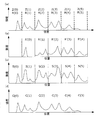
ここで、図1を用いて、本実施形態に係る光干渉断層撮像装置で実像及び所望の断層像を得るための方法(本実施形態に係る光干渉断層撮像方法)の原理について説明する。図1において、縦軸は反射強度(光の強度)を表し、横軸は被検査物内の(照射方向の)位置を表す。図1(a)は被検査物の理想的な断層像を示している。本実施形態では被検査物を等間隔の測定領域Z(0)〜Z(5)に分け、領域毎に測定を行う。また、符号R(0)〜R(5)は、それぞれ、測定領域Z(0)〜Z(5)の実像を示す。本実施形態では、第1の測定領域として測定領域Z(0)を被検査物の端に配置する。そして、第1から第Xの測定領域(Xは1より大きい整数;図1の例では測定領域Z(0)〜Z(5))が測定光の照射方向に順に並ぶように、複数の測定領域を設定する。なお、OCT装置では、屈折率差の大きなところが大きな信号として測定される。従って、被検査物の端の領域とは、屈折率差が無視できるような範囲に隣接する領域である。なお、被検査物の内部であっても測定領域の幅以上の範囲で屈折率の差が無視できれば、当該測定領域とその外側の領域とでは違う物体とみなすことができるため、そのような測定領域を被検査物の端の領域とみなしてもよい。 Here, the principle of a method for obtaining a real image and a desired tomographic image with the optical coherence tomography apparatus according to the present embodiment (the optical coherence tomography method according to the present embodiment) will be described with reference to FIG. In FIG. 1, the vertical axis represents the reflection intensity (light intensity), and the horizontal axis represents the position (in the irradiation direction) within the inspection object. FIG. 1A shows an ideal tomographic image of the inspection object. In the present embodiment, the object to be inspected is divided into equally spaced measurement areas Z (0) to Z (5), and measurement is performed for each area. Symbols R (0) to R (5) indicate real images of the measurement regions Z (0) to Z (5), respectively. In the present embodiment, the measurement region Z (0) is arranged at the end of the inspection object as the first measurement region. A plurality of measurements are performed such that the first to Xth measurement regions (X is an integer greater than 1; in the example of FIG. 1, measurement regions Z (0) to Z (5)) are sequentially arranged in the irradiation direction of the measurement light. Set the area. In the OCT apparatus, a portion having a large refractive index difference is measured as a large signal. Therefore, the region at the end of the object to be inspected is a region adjacent to a range where the refractive index difference can be ignored. Note that even if the difference in refractive index can be ignored within the range of the measurement area even within the inspection object, it can be regarded as a different object in the measurement area and the outside area, so that measurement is possible. The region may be regarded as the region at the end of the inspection object.
図1(b)はコヒーレンスゲートを測定領域Z(i−1)と測定領域Z(i)の境界(i>1)に置いたときに、測定領域Z(i)に映り込む鏡像(測定領域Z(i)の実像に重ね合わさる鏡像)を模式的に示している。測定領域Z(i)に映り込む鏡像は、測定領域Z(i−1)の実像の鏡像であるため、当該鏡像を符合R’(i−1)で示す。なお、i=0の測定領域(測定領域Z(0))は被検査物の端部の領域であるため鏡像が現れない。 FIG. 1B shows a mirror image (measurement region) reflected in the measurement region Z (i) when the coherence gate is placed at the boundary (i> 1) between the measurement region Z (i-1) and the measurement region Z (i). A mirror image superimposed on a real image of Z (i) is schematically shown. Since the mirror image reflected in the measurement region Z (i) is a mirror image of the real image of the measurement region Z (i-1), the mirror image is indicated by a symbol R ′ (i−1). In addition, since the measurement area | region (measurement area Z (0)) of i = 0 is an area | region of the edge part of a to-be-inspected object, a mirror image does not appear.
図1(c)はコヒーレンスゲートを測定領域Z(i−1)と測定領域Z(i)の境界に置いたときの各測定領域の測定像S(0)〜S(5)を示す。測定領域Z(1)〜Z(5)の測定像は実像に鏡像が重ね合わさった像となるが、上述したように測定領域Z(0)では鏡像が現れないため、測定領域Z(0)の測定像S(0)は実像となる。測定像S(i)は式1−1,1−2で表される。
S(i)=R(i) i=0 (式1−1)
S(i)=R(i)+R’(i−1) i=1〜5 (式1−2)
式1−1は、測定領域Z(0)の測定像S(0)が実像R(0)であることを表している。式1−2は、測定領域Z(i)の測定像S(i)から実像R(i−1)の鏡像R’(i−1)を減算することによって、測定領域Z(i)の実像R(i)を得ることができることを示している。
FIG. 1C shows measurement images S (0) to S (5) of each measurement region when the coherence gate is placed at the boundary between the measurement region Z (i-1) and the measurement region Z (i). The measurement images in the measurement regions Z (1) to Z (5) are images obtained by superimposing the mirror image on the real image. However, since the mirror image does not appear in the measurement region Z (0) as described above, the measurement region Z (0). The measured image S (0) is a real image. The measurement image S (i) is represented by Formulas 1-1 and 1-2.
S (i) = R (i) i = 0 (Formula 1-1)
S (i) = R (i) + R ′ (i−1) i = 1 to 5 (Formula 1-2)
Expression 1-1 represents that the measurement image S (0) in the measurement region Z (0) is a real image R (0). Equation 1-2 subtracts the mirror image R ′ (i−1) of the real image R (i−1) from the measurement image S (i) of the measurement region Z (i), thereby obtaining the real image of the measurement region Z (i). It shows that R (i) can be obtained.
測定像から鏡像を除去することによって得られた実像を符号C(i)とすると、実像C(i)は式2−1,2−2で表される(符合C’(i−1)は実像C(i−1)の鏡像を示す)。
C(i)=S(i) i=0 (式2−1)
C(i)=S(i)−C’(i−1) i=1〜5 (式2−2)
鏡像C’(i−1)は実像C(i−1)から算出することができる。上述したように、第1の測定領域(測定領域Z(0))では鏡像が現れないため、本実施形態では、第1の測定領域について、測定像S(0)を断層像(実像)C(0)として採用する。そして、第2〜第Xの測定領域については順番に、第Yの測定領域の測定像から(2≦Y≦X)、第Y−1の測定領域の実像の鏡像を除去することにより、第Yの実像を得る。即ち、図1の例では、i=1から5まで順番に実像C(i)を計算する。それにより、測定領域毎の実像を得ることができる。そして、得られた実像を繋ぎ合わせることによって所望の断層像を得ることができる(図1(d))。
When a real image obtained by removing the mirror image from the measurement image is denoted by C (i), the real image C (i) is expressed by equations 2-1 and 2-2 (sign C ′ (i−1) is A mirror image of the real image C (i-1) is shown).
C (i) = S (i) i = 0 (Formula 2-1)
C (i) = S (i) −C ′ (i−1) i = 1 to 5 (Formula 2-2)
The mirror image C ′ (i−1) can be calculated from the real image C (i−1). As described above, since a mirror image does not appear in the first measurement region (measurement region Z (0)), in the present embodiment, the measurement image S (0) is tomographic image (real image) C for the first measurement region. Adopt as (0). Then, for the second to Xth measurement areas, the mirror image of the real image of the Y-1th measurement area is removed from the measurement image of the Yth measurement area (2 ≦ Y ≦ X) in turn. A real image of Y is obtained. That is, in the example of FIG. 1, the real image C (i) is calculated in order from i = 1 to 5. Thereby, a real image for each measurement region can be obtained. A desired tomographic image can be obtained by joining the obtained real images (FIG. 1 (d)).
なお、本実施形態では、i=1から順番に実像C(i)を計算するものとしたが、計算方法はこれに限らない。例えば、測定領域Z(5)を被検査物の端に配置し、コヒーレンスゲートを測定領域Z(I+1)と測定領域Z(I)の境界においた場合には(Iは0以上y以下の整数であり、図1の例ではy=4となる)、測定領域Z(5)を第1の測定領域としてもよい。具体的には、そのような場合には測定像S(5)は実像C(5)となり、測定領域Z(I)に測定領域Z(I+1)の実像C(I+1)の鏡像が映り込むため、測定像S(I)から鏡像C’(I+1)を減算することで実像C(I)を得ることができる。I=4から0まで順番に実像C(I)を計算することにより、各測定領域の実像を得ることができる。 In the present embodiment, the real image C (i) is calculated in order from i = 1, but the calculation method is not limited to this. For example, when the measurement region Z (5) is arranged at the end of the inspection object and the coherence gate is at the boundary between the measurement region Z (I + 1) and the measurement region Z (I) (I is an integer of 0 or more and y or less) 1 and y = 4 in the example of FIG. 1), the measurement region Z (5) may be the first measurement region. Specifically, in such a case, the measurement image S (5) becomes a real image C (5), and a mirror image of the real image C (I + 1) of the measurement region Z (I + 1) is reflected in the measurement region Z (I). The real image C (I) can be obtained by subtracting the mirror image C ′ (I + 1) from the measurement image S (I). By calculating the real image C (I) in order from I = 4 to 0, a real image of each measurement region can be obtained.
また、被検査物の内部を端とする場合、例えば、測定領域Z(2)と測定領域Z(4)が被検査物の端の領域であり、測定領域Z(3)に構造がない場合が考えられる。その場合に、測定領域Z(i−1)と測定領域Z(i)の境界にコヒーレンスゲートを設置すると、測定像S(3)は実像C(2)の鏡像となり、測定像S(4)は実像C(4)となる。そのため、このような場合には、上述した方法と同様の方法で、測定領域Z(0),Z(1),Z(5)の実像を計算すればよい。 Further, when the inside of the inspection object is an end, for example, the measurement region Z (2) and the measurement region Z (4) are the end region of the inspection object, and the measurement region Z (3) has no structure. Can be considered. In that case, if a coherence gate is installed at the boundary between the measurement region Z (i-1) and the measurement region Z (i), the measurement image S (3) becomes a mirror image of the real image C (2), and the measurement image S (4). Becomes a real image C (4). Therefore, in such a case, a real image of the measurement region Z (0), Z (1), Z (5) may be calculated by a method similar to the method described above.
このように、本実施形態に係る光干渉断層撮像装置では、各測定領域の測定を最低一回行い、それらのデータを用いて各測定領域の実像を計算する。具体的には、他の領域の実像を用いて測定像の鏡像を除去するという簡易な方法で、短時間で断層像を得ることがで
きる。さらに、得られた実像(断層像)を繋ぎ合わせることにより、被検査物の測定範囲が大きく、横方向の分解能が高い断層像を高速で取得することができる。それにより、高速なダイナミックフォーカスのOCT装置を実現することができる。
As described above, in the optical coherence tomography apparatus according to the present embodiment, each measurement region is measured at least once, and a real image of each measurement region is calculated using the data. Specifically, a tomographic image can be obtained in a short time by a simple method of removing a mirror image of a measurement image using a real image of another region. Furthermore, by connecting the obtained real images (tomographic images), a tomographic image having a large measurement range of the inspection object and high lateral resolution can be acquired at high speed. As a result, a high-speed dynamic focus OCT apparatus can be realized.
<実施例1>
次に本実施形態に係る光干渉断層撮像装置の具体的な実施例について説明する。具体的には、本発明を適用した眼科用のOCT装置について説明する。
<Example 1>
Next, specific examples of the optical coherence tomography apparatus according to this embodiment will be described. Specifically, an ophthalmic OCT apparatus to which the present invention is applied will be described.
<光学系の構成>
図2は、本実施例に係るOCT装置で用いられるマッハツェンダー干渉系の構成を示す図である。光源201から出射された光(出射光)はシングルモードファイバー202−1を通して、レンズ211−1に導かれる。出射光は、ビームスプリッタ203−1によって参照光205と測定光206に分割される。測定光206は、被検査物である眼207に照射された後、反射や散乱により戻り光208となって戻される。参照光と戻り光はビームスプリッタ203−2、レンズ211−2、シングルモードファイバー202−3を介して、分光器218に入射する。分光器で取得された光(戻り光と参照光の干渉光)の波長スペクトルなどのデータは、コンピューター219に入力される。なお、光源201は代表的な低コヒーレント光源であるSLD(Super Luminescent Diode)である。被検査物が眼であることを鑑みると、出射光は近赤外光(例えば中心波長840nm、帯域50nmの光)であることが好ましい。
<Configuration of optical system>
FIG. 2 is a diagram illustrating a configuration of a Mach-Zehnder interference system used in the OCT apparatus according to the present embodiment. Light (emitted light) emitted from the
参照光205の参照光路について説明する。ビームスプリッタ203−1によって分割された参照光205はミラー214−1〜3に順次入射する。そして、ビームスプリッタ203−2に導かれ、分光器に入射する。なお、参照光205は、ミラー214−1とミラー214−2の間で分散補償用ガラス215−1内を通る。分散補償用ガラス215−1の長さはL1であり、一般的な眼の奥行きの2倍に等しいことが望ましい。これは、眼207内で測定光206が反射、散乱する際の分散を、参照光205に対して補償するためである。本実施例では、長さL1を日本人の平均的な眼球の直径とされる23mmの2倍の46mmとする。さらに、ミラー214−1,214−2は、ミラー駆動機構213によって、矢印で図示している方向に動かすことができる。ミラー214−1,214−2の位置を動かすことにより、参照光205の光路長を調整・制御することができる。また、参照光205は、ミラー214−2とミラー214−3の間で分散補償用ガラス215−2内を通る。分散補償用ガラス215−2は眼のスキャンに用いられる対物レンズ216、スキャンレンズ217の分散補償のために用いられる。
The reference light path of the
測定光206の測定光路について説明する。ビームスプリッタ203−1によって分割された測定光206は、ビームスプリッタ203−3で反射され、XYスキャナ204のミラーに入射する。XYスキャナ204は、網膜210上を光軸(照射方向)に垂直な方向にラスタースキャンするものである。また、測定光206の中心はXYスキャナ204のミラーの回転中心と一致するように調整されている。対物レンズ216、スキャンレンズ217は、網膜210を走査する(測定光を網膜の様々な位置へ導く)ための光学系であり、角膜209の付近を支点として、網膜210をスキャンするために用いられる。本実施例では、対物レンズ216、スキャンレンズ217の焦点距離をそれぞれ50mm、50mmとする。対物レンズ216の(照射方向の)焦点位置は、フォーカス駆動機構212によって調整することができる。測定光206は眼207に入射すると、網膜210で反射や散乱し、戻り光208となって戻される。戻り光208はビームスプリッタ203−3まで測定光206と同様の光路を通り、ビームスプリッタ203−3を通過する。そして、ビームスプリッタ203−2へ導かれ、分光器に入射する。
The measurement optical path of the
なお、フォーカス駆動機構、ミラー駆動機構、XYスキャナー、分光器はコンピュータ
ー219によって制御され、所望の動作が実行される。またコンピューターは、分光器のデータの処理、データの保存、画像の処理などを行う。
The focus drive mechanism, mirror drive mechanism, XY scanner, and spectroscope are controlled by the
<測定範囲>
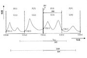
次に、測定領域の(照射方向の)幅について図3を用いて説明する。図3において、縦軸は反射強度を表し、横軸は被検査物内の(照射方向の)位置を表す。図3は、コヒーレンスゲート301を測定領域Z(3)とそれに隣接する測定領域Z(2)の間に配置して、測定領域Z(3)について測定を行う場合を模式的に示している。符号302は各測定領域の幅を示し、符号303は測定深度、符号304は焦点深度を示す。測定深度と焦点深度については後述する。
<Measurement range>
Next, the width (in the irradiation direction) of the measurement region will be described with reference to FIG. In FIG. 3, the vertical axis represents the reflection intensity, and the horizontal axis represents the position (in the irradiation direction) within the inspection object. FIG. 3 schematically shows a case where the
焦点深度(DOF)は、得られる像の視認可能な範囲を表す。焦点深度は、被検査物内に測定光を集束させるために用いるレンズの開口数NAと光源の中心波長λを用いて式3(光学距離)のように表される。図3では、式3で得られる範囲のプラス側を実線で示し、マイナス側を破線で示している。
DOF=±λ/(2NA2) (式3)
The depth of focus (DOF) represents a visible range of the obtained image. The depth of focus is expressed as Equation 3 (optical distance) using the numerical aperture NA of the lens used for focusing the measurement light in the inspection object and the center wavelength λ of the light source. In FIG. 3, the plus side of the range obtained by
DOF = ± λ / (2NA 2 ) (Formula 3)
被検査物が眼で、被検査物を6つの測定領域に分ける場合に、各測定領域の幅が500μmであれば、焦点深度は全長1000μm(±500μm)より長いことが望ましい。なお、一般的なSD−OCT装置では、焦点深度は全長3mm程度である。当然、分割数を多くすれば、測定領域を小さくすることができるため、焦点深度を小さくすることができる。なお、焦点深度を多少超える範囲であっても測定できないわけではない。また、焦点は必ずしもコヒーレンスゲートの位置に設定する必要はない。ただし、均質な画像を得るために、焦点深度は、各測定領域の幅より大きいことが望ましい。OCT装置の場合には、ビームの直径を変更することでNAを変更することができる。一般的には眼に入射するビームの直径を大きくすれば、NAが大きくなる。 When the object to be inspected is an eye and the object to be inspected is divided into six measurement areas, if the width of each measurement area is 500 μm, the depth of focus is preferably longer than the total length of 1000 μm (± 500 μm). In a general SD-OCT apparatus, the depth of focus is about 3 mm in total length. Of course, if the number of divisions is increased, the measurement area can be reduced, so that the depth of focus can be reduced. In addition, even if it is in a range slightly exceeding the depth of focus, it is not impossible to measure. Further, the focal point is not necessarily set at the position of the coherence gate. However, in order to obtain a uniform image, it is desirable that the depth of focus is larger than the width of each measurement region. In the case of an OCT apparatus, the NA can be changed by changing the beam diameter. In general, increasing the diameter of the beam incident on the eye increases the NA.
測定深度は、エリアシングの発生しない範囲を表す(エリアシングが発生すると測定が困難となる)。測定深度は、分光器のラインセンサーの画素数N(偶数、通常は2の階乗で、1024や2048である。)、分光器の検出する波数のスペクトル幅ΔKを用いて式4(光学距離)のように表される。図3には式4で得られる範囲のプラス側を実線で示し、マイナス側を破線で示している。
Lmax=±N/(4ΔK) (式4)
The measurement depth represents a range where aliasing does not occur (measurement becomes difficult when aliasing occurs). The depth of measurement is expressed by Equation 4 (optical distance) using the number N of pixels of the line sensor of the spectrometer (an even number, usually a factorial of 2 is 1024 or 2048) and the spectral width ΔK of the wave number detected by the spectrometer. ). In FIG. 3, the plus side of the range obtained by
Lmax = ± N / (4ΔK) (Formula 4)
測定光の中心波長が840nm、帯域が50nm、分光器のラインセンサーの画素数が1024であれば、光学距離で±3.4mm程度の範囲まで測定できることになる。なお、式4で示される測定深度は理論的な値であり、実際には分光器の分解能によって実効的なサンプリング数がNより小さくなる。このため、正確に復元(測定)できる範囲は理論的な測定深度より小さくなる。従って、測定領域の幅は理論的な測定深度より小さくするように設定する必要がある。通常は、測定領域の幅<理論的な測定深度を満たしている。さらに、均質な画像を得るためには、焦点深度(全長)と測定領域の幅の関係は式5の関係を満たすことが好ましい。即ち、測定領域の幅は、当該測定領域の測定像を得る際の焦点深度の1/2よりも小さいことが好ましい。
2 × 測定領域の幅 < 焦点深度(全長) (式5)
If the center wavelength of the measurement light is 840 nm, the bandwidth is 50 nm, and the number of pixels of the line sensor of the spectrometer is 1024, the optical distance can be measured to a range of about ± 3.4 mm. Note that the measurement depth represented by
2 x width of measurement area <depth of focus (full length) (Formula 5)
また、離散フーリエ変換では測定像を構成する各要素は、式6(光学距離)で与えられる離散的な値となる。ここで、tは、0≦t≦N/2の整数である。
L=t/(2ΔK) (式6)
In the discrete Fourier transform, each element constituting the measurement image is a discrete value given by Expression 6 (optical distance) . Here, t is an integer of 0 ≦ t ≦ N / 2.
L = t / (2ΔK) (Formula 6)
また、測定分解能δ(L)は、式7のように表される。測定分解能δ(L)は一画素あたりの間隔でもある。本実施例では測定分解能δ(L)は光学距離で6.8μm程度となる。
Lmin=δ(L)=1/(2ΔK) (式7)
Further, the measurement resolution δ (L) is expressed as in Expression 7. The measurement resolution δ (L) is also an interval per pixel. In this embodiment, the measurement resolution δ (L) is about 6.8 μm in terms of optical distance.
Lmin = δ (L) = 1 / (2ΔK) (Expression 7)
<信号処理>
図1および図4を用いて、測定像のデータ(測定像データ)の解析方法について説明する。本実施例では、測定領域Z(i−1)と測定領域Z(i)の境界にコヒーレンスゲートを設置し、測定領域Z(i)について測定を行う場合について説明する。以下、測定領域Z(i)の測定像データを符号S(i,k)として表記する。iは領域の番号0〜M−1であり、kは領域内の要素の番号0〜nある(iとnはいずれも整数である)。Mは領域数、nはn<N/2を満たす要素数である。Nはラインセンサーの画素数である。測定領域の幅が500μm程度であれば(本実施例ではδ(L)=6.8μmであるため)、n=500/6.8=74画素程度となる。測定領域の幅は分割数を多くすることで小さくすることができるため、nはラインセンサーの画素数に対し小さくなる。なお、ここでは、測定像データS(i,0)と測定像データS(i−1,n)の位置は一致するものとし、この位置にコヒーレンスゲートが配置されているものとする。同様に各測定領域の実像のデータ(実像データ)は符号C(i,k)として表記する。
<Signal processing>
A method for analyzing measurement image data (measurement image data) will be described with reference to FIGS. 1 and 4. In the present embodiment, a case where a coherence gate is installed at the boundary between the measurement region Z (i-1) and the measurement region Z (i) and measurement is performed on the measurement region Z (i) will be described. Hereinafter, the measurement image data of the measurement region Z (i) is expressed as a code S (i, k). i is a
ステップS1の工程で、測定を開始する。なお、iの初期値を0とする。 In the step S1, measurement is started. Note that the initial value of i is 0.
ステップS2の工程では、測定領域Z(i)(即ち、Z(0))の測定像データを測定する(測定像取得手段)。被検査物が眼であるので、網膜に対して角膜側をコヒーレンスゲートの設置位置とする。コヒーレンスゲートを角膜側に配置してから、網膜側に移動させていくと測定像が変化し始める。具体的には、コヒーレンスゲートの移動と同期して、測定像がコヒーレンスゲート側に近づく。移動した結果、所望の位置になったところで測定領域Z(0)に対する測定を行う。所望の位置とは鏡像の発生しないような領域である。なお、フォーカス位置は、ミラーの位置と同期して動かされる。測定領域Z(0)には鏡像が発生しないため、実像C(0,k)は、式8に示すように測定像S(i,k)からを直接得ることができる。そして、iに1を加算し、ステップS3へ進む。
C(0,k)=S(0,k) 0≦k≦n (式8)
In step S2, the measurement image data in the measurement region Z (i) (that is, Z (0)) is measured (measurement image acquisition means). Since the object to be inspected is the eye, the corneal side with respect to the retina is set as the coherence gate installation position. When the coherence gate is arranged on the cornea side and then moved to the retina side, the measurement image starts to change. Specifically, the measurement image approaches the coherence gate side in synchronization with the movement of the coherence gate. As a result of the movement, the measurement region Z (0) is measured at a desired position. The desired position is an area where no mirror image is generated. The focus position is moved in synchronization with the mirror position. Since no mirror image is generated in the measurement region Z (0), the real image C (0, k) can be obtained directly from the measurement image S (i, k) as shown in Equation 8. Then, 1 is added to i, and the process proceeds to step S3.
C (0, k) = S (0, k) 0 ≦ k ≦ n (Formula 8)
ステップS3の工程では、コヒーレンスゲートを測定領域Z(i−1)と測定領域Z(i)の境界に配置し、測定領域Z(i)に対する測定を行う。具体的には、測定領域Z(i)での測定像データS(i,k)を得る(測定像取得手段)。なお、測定像データS(0,0)は断層に起因するデータではない(その要素の位置には被測定物の構造が無い)ため、測定像データS(0,0)の代わりに測定像データS(0,1)を用いてもよい。 In the step S3, a coherence gate is arranged at the boundary between the measurement region Z (i-1) and the measurement region Z (i), and measurement is performed on the measurement region Z (i). Specifically, measurement image data S (i, k) in the measurement region Z (i) is obtained (measurement image acquisition means). Note that the measurement image data S (0,0) is not data resulting from the tomography (the structure of the object to be measured is not present at the position of the element), and thus the measurement image data S (0,0) is used instead of the measurement image data S (0,0). Data S (0, 1) may be used.
ステップS4の工程では、ステップS3の工程で得られた測定像データS(i,k)か
ら鏡像データを除去して、実像データC(i,k)を得る(断層像取得手段)。除去する鏡像データは、コヒーレンスゲートの位置(本実施例では測定領域と、その測定領域に隣接する隣接領域との境界)を軸として反転させることにより得られる。具体的には、測定像データS(i,k)から、鏡像データとして、実像データC(i−1,n−k)を除去する。なお、実像データC(i,0)は、コヒーレンスゲートの配置位置のデータであるため、実像データC(i−1,n)と等しいものとする(式9−1)。算出される実像データC(i,k)は式9−2のように表される。
C(i,0)=C(i−1,n) k=0 (式9−1)
C(i,k)=S(i,k)−C(i−1,n−k) 0<k≦n (式9−2)
In step S4, the mirror image data is removed from the measurement image data S (i, k) obtained in step S3 to obtain real image data C (i, k) (tomographic image acquisition means). The mirror image data to be removed is obtained by inverting the position of the coherence gate (in this embodiment, the boundary between the measurement region and the adjacent region adjacent to the measurement region) as an axis. Specifically, the real image data C (i−1, nk) is removed as the mirror image data from the measurement image data S (i, k). Since the real image data C (i, 0) is data of the arrangement position of the coherence gate, it is assumed to be equal to the real image data C (i-1, n) (Equation 9-1). The calculated real image data C (i, k) is expressed as in Expression 9-2.
C (i, 0) = C (i-1, n) k = 0 (Formula 9-1)
C (i, k) = S (i, k) −C (i−1, nk) 0 <k ≦ n (Formula 9-2)
ステップS5の工程では、測定領域毎に得られた実像データC(i,k)を繋ぎ合わせる。そして、iが所望の値(図1の例では5)よりも小さい場合(測定を続ける場合)には(ステップS6:Yes)、iに1を加算し、ステップS3へ戻る。iが所望の値に達した場合(i=5の場合;測定を終了する場合)には(ステップS6:NO)、ステップS7へ進み、処理を終了する。全ての領域の実像データが繋ぎ合せられることにより、所望の断層像が得られる。 In step S5, the real image data C (i, k) obtained for each measurement region is connected. When i is smaller than a desired value (5 in the example of FIG. 1) (when measurement is continued) (step S6: Yes), 1 is added to i, and the process returns to step S3. When i reaches a desired value (when i = 5; when the measurement is terminated) (step S6: NO), the process proceeds to step S7, and the process is terminated. A desired tomographic image is obtained by connecting the real image data of all the regions.
なお、ここでは、測定領域の境界にコヒーレンスゲートを配置して計算していたが、S(i,k)のiが低次の成分には光源のスペクトルに起因する誤差が混入する場合がある。そのような場合には、測定像を得る際に、コヒーレンスゲートの位置を、測定領域とその隣接領域との境界よりも隣接領域側に設定すればよい。例えば、測定領域Z(i)について測定を行う場合に、測定領域Z(i−1)と測定領域Z(i)の境界からi−1側へ数〜数十要素分シフトさせる。シフトさせる要素数は、光源のコヒーレンス関数などによって決めればよい。 Here, the calculation is performed by arranging a coherence gate at the boundary of the measurement region. However, an error due to the spectrum of the light source may be mixed in a component of low-order i in S (i, k). . In such a case, when a measurement image is obtained, the position of the coherence gate may be set closer to the adjacent region than the boundary between the measurement region and the adjacent region. For example, when measurement is performed on the measurement region Z (i), the measurement region Z (i-1) is shifted from the boundary between the measurement region Z (i) to the i-1 side by several to several tens of elements. The number of elements to be shifted may be determined by the coherence function of the light source.
また、ここでは、実像を取得するたびに当該実像を他の実像に繋ぎあわせているが、先に実像を全て取得した後に、それらを繋ぎあわせてもよい。また、先に測定像を全て取得した後に、実像を計算してもよい。当然、被検査物の構造が不明な場合には、鏡像が発生していない測定領域を検索する工程を入れてもよい。鏡像が発生していない測定領域とは、コヒーレンスゲートを移動させて、一方向にしか測定像が動かないようなところである。 Here, every time a real image is acquired, the real image is connected to another real image. However, after all the real images are acquired first, they may be connected. Alternatively, the real image may be calculated after all the measurement images have been acquired. Naturally, when the structure of the object to be inspected is unknown, a step of searching for a measurement region where no mirror image is generated may be included. The measurement area where no mirror image is generated is a place where the measurement image moves only in one direction by moving the coherence gate.
<実施例2>
実施例2では、SD−OCT特有の現象による問題を解決する方法について説明する。SD−OCT特有の現象について図5を用いて説明する。図5は、被検査物としてミラーを用いたときの、コヒーレンスゲートとミラーの間の距離と測定される反射強度の関係を示す図である。具体的には、ミラーの位置をコヒーレンスゲートから、50、100、150、200、300、400、500、600、800、1000、1200、1600、2000μm離したときに測定された反射強度(デジタル値)をそれぞれ示している。点線は、それらの結果の包絡線(測定領域内の照射方向の位置に対する反射強度の変化)を模式的に示しており、いわゆる減衰関数である。図5では、ミラーの位置がコヒーレンスゲートから離れるにつれて強度が減衰している。これはRoll−Offなどと呼ばれ、分光器の解像度などに起因して発生する。
<Example 2>
In the second embodiment, a method for solving a problem caused by a phenomenon peculiar to SD-OCT will be described. A phenomenon peculiar to SD-OCT will be described with reference to FIG. FIG. 5 is a diagram showing the relationship between the distance between the coherence gate and the mirror and the measured reflection intensity when a mirror is used as the object to be inspected. Specifically, the reflection intensity (digital value) measured when the mirror position is separated from the coherence gate by 50, 100, 150, 200, 300, 400, 500, 600, 800, 1000, 1200, 1600, 2000 μm. ) Respectively. The dotted line schematically shows the resulting envelope curve (change in reflection intensity with respect to the position in the irradiation direction within the measurement region), and is a so-called attenuation function. In FIG. 5, the intensity is attenuated as the position of the mirror moves away from the coherence gate. This is called Roll-Off or the like and occurs due to the resolution of the spectroscope.
上述したように、この現象が発生する場合には、コヒーレンスゲートに近い位置では強度が強く、遠くなれば強度が弱くなる。そのため、測定領域の境目において、一方の領域では強度が強く、他方の領域では強度が弱くなる。それにより、隣接する領域間において、測定される強度に飛びが発生してしまう。 As described above, when this phenomenon occurs, the intensity is high near the coherence gate, and the intensity decreases as the distance increases. Therefore, at the boundary of the measurement region, the strength is high in one region and the strength is weak in the other region. This causes a jump in the measured intensity between adjacent regions.
<信号処理>
このような現象が発生するときの信号処理の方法(測定像データの解析方法)について図6を用いて説明する。
ステップS2−1で測定を開始する。
ステップS2−2〜S2−4で、測定領域を切り換えながら順次測定像データを取得する。なお、本実施例では、測定像が、その測定領域の幅(例えば、500μm(0≦k≦n))よりも広い範囲(例えば、0≦k≦N−1)に対して得られるものとする。
ステップS2−5〜S2−6で、各測定領域の測定像データを上述した減衰関数に基づいて決定された補正関数に従って順次補正する。具体的には、光干渉断層撮像装置は上述した補正関数を予め記憶または取得し、測定位置(要素の位置)毎に、その位置に対応する補正関数の値(補正関数にその位置を代入することにより得られる値;補正データ)を用いて補正する。補正に用いるデータを補正データD(i,k)とすると、補正された測定像データH(i,k)は式10のように表される。
H(i,k)=S(i,k)/D(i,k) (式10)
なお、補正関数は、理論や実験で得られた減衰関数そのものであってもよいし、減衰関数の近似関数(直線や2次曲線)であってもよいし、減衰関数に所定の係数を加算や乗算したものであってもよい。上述したような現象を解消することができればどのような関数を用いてもよい。
<Signal processing>
A signal processing method (analysis method of measurement image data) when such a phenomenon occurs will be described with reference to FIG.
In step S2-1, measurement is started.
In steps S2-2 to S2-4, measurement image data is sequentially acquired while switching the measurement region. In this embodiment, the measurement image is obtained over a range (for example, 0 ≦ k ≦ N−1) wider than the width of the measurement region (for example, 500 μm (0 ≦ k ≦ n)). To do.
In steps S2-5 to S2-6, the measurement image data of each measurement region is sequentially corrected according to the correction function determined based on the above-described attenuation function. Specifically, the optical coherence tomography apparatus previously stores or acquires the above-described correction function, and substitutes the value of the correction function corresponding to the position (the position into the correction function) for each measurement position (element position). Is corrected using the value obtained by this; correction data). Assuming that the data used for correction is correction data D (i, k), the corrected measurement image data H (i, k) is expressed by Equation 10.
H (i, k) = S (i, k) / D (i, k) (Equation 10)
The correction function may be the attenuation function itself obtained by theory or experiment, or may be an approximate function (straight line or quadratic curve) of the attenuation function, or a predetermined coefficient is added to the attenuation function. Or may be multiplied. Any function may be used as long as the phenomenon as described above can be eliminated.
以後の処理は、実施例1と同様である。具体的には、測定像データS(i,k)の代わりに補正された測定像データH(i,k)を用いる。 The subsequent processing is the same as in the first embodiment. Specifically, corrected measurement image data H (i, k) is used instead of the measurement image data S (i, k).
なお、補正関数は一つであってもよいが、測定領域毎に特性(上述した現象の特性;減衰関数)が異なるような場合には、領域ごとに補正関数を用意することが好ましい(補正関数が測定領域ごとに異なっていることが好ましい。)。例えば、焦点深度が焦点の位置によって変わる場合には、測定領域毎に特性が変わるため、有効である。 Although there may be one correction function, it is preferable to prepare a correction function for each region when the characteristics (characteristics of the phenomenon described above; attenuation function) are different for each measurement region (correction). The function is preferably different for each measurement area). For example, when the depth of focus changes depending on the position of the focus, the characteristics change for each measurement region, which is effective.
ステップS2−7〜S2−9では、測定像から鏡像を除去して測定領域ごとの実像を得るとともに、測定領域毎に実像の画像調整を行う。画像調整は、実像の画素値と測定領域の位置(測定光の照射方向の位置)の調整である。例えば、実施例1では、実像データC(i,0)と実像データC(i−1,n)の位置は一致するものとしたが、それらの位置は互いにずれる場合がある。これは、コヒーレンスゲートの位置誤差、光源の強度誤差などに起因する。 In steps S2-7 to S2-9, the mirror image is removed from the measurement image to obtain a real image for each measurement region, and image adjustment of the real image is performed for each measurement region. Image adjustment is adjustment of the pixel value of a real image and the position of a measurement area (position in the irradiation direction of measurement light). For example, in the first embodiment, the positions of the real image data C (i, 0) and the real image data C (i−1, n) coincide with each other, but the positions may be shifted from each other. This is caused by a coherence gate position error, a light source intensity error, and the like.
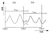
図7を用いて、画像調整について説明する。図7において、縦軸は反射強度を表し、横軸は被検査物内の(照射方向の)位置を表す。図7では、互いに隣接する測定領域Z(3),Z(4)の実像を、それぞれ、実線、破線で示している。測定領域Z(i)の実像は、k>nの範囲で測定領域Z(i+1)の実像に重複している。画像調整には重複部分のデータの一部または全部を使用する。また、k>nの範囲で得られた実像データ間を補間し、当該補間によって得られるデータを使用してもよい。理想的には、この重複部分が一致するように実像データを調整する。なお、以下では、測定領域Z(3)の実像に対する調整は済んでいるものとし、測定領域Z(3)の実像に一致するように測定領域Z(4)の実像を調整する場合について説明する。 Image adjustment will be described with reference to FIG. In FIG. 7, the vertical axis represents the reflection intensity, and the horizontal axis represents the position (in the irradiation direction) within the inspection object. In FIG. 7, the real images of the measurement regions Z (3) and Z (4) adjacent to each other are indicated by a solid line and a broken line, respectively. The real image of the measurement region Z (i) overlaps the real image of the measurement region Z (i + 1) in the range of k> n. Some or all of the overlapping data is used for image adjustment. Alternatively, real image data obtained in a range of k> n may be interpolated and data obtained by the interpolation may be used. Ideally, the real image data is adjusted so that the overlapping portions match. In the following description, it is assumed that the real image of the measurement region Z (3) has been adjusted, and a case where the real image of the measurement region Z (4) is adjusted to match the real image of the measurement region Z (3) will be described. .
測定領域の位置の調整(即ち、図7の横軸方向の調整)は、測定領域の断層像とその隣接領域の断層像(実線と破線)の重複部分の強度差が一定となるように行われる。即ち、実線と破線の重複部分の強度差が一定になるように(例えば、重複部分の強度差の分散が
最小になるように)破線を横軸方向にシフトさせる。重複部分において、互いの実像のそれぞれに特定のピークがある場合には、それらのピーク位置が一致するように調整してもよい。そして、強度の調整(即ち、図7の縦軸方向の調整)は、測定領域の断層像とその隣接領域の断層像(実線と破線)の重複部分の強度差が最小になるように行われる。即ち、実線と破線の重複部分の強度差が最小になるように(例えば、重複部分の強度差の絶対値の合計が最小になるように)破線を縦軸方向にシフトさせる。なお、画像調整は測定領域の位置、または、強度のいずれかのみを調整するものであってもよい。測定領域の位置と強度の両方の調整を行う場合には、測定領域の位置を調整した後に強度を調整することが好ましい。
Adjustment of the position of the measurement region (that is, adjustment in the horizontal axis direction in FIG. 7) is performed so that the intensity difference between the overlapping portions of the tomographic image of the measurement region and the tomographic image of the adjacent region (solid line and broken line) becomes constant. Is called. That is, the broken line is shifted in the horizontal axis direction so that the intensity difference between the overlapping portions of the solid line and the broken line is constant (for example, the variance of the intensity difference between the overlapping portions is minimized). In the overlapping portion, when there are specific peaks in each of the real images, the peak positions may be adjusted to match. Then, the intensity adjustment (that is, the adjustment in the vertical axis direction in FIG. 7) is performed so that the intensity difference between overlapping portions of the tomographic image of the measurement region and the tomographic image of the adjacent region (solid line and broken line) is minimized. . That is, the broken line is shifted in the vertical axis direction so that the intensity difference between the overlapping portions of the solid line and the broken line is minimized (for example, the sum of the absolute values of the intensity differences of the overlapping portions is minimized). Note that the image adjustment may be to adjust only the position of the measurement region or the intensity. When adjusting both the position and intensity of the measurement region, it is preferable to adjust the intensity after adjusting the position of the measurement region.
ステップS2−10では、各測定領域について得られた実像を繋ぎ合わせる。それにより、ステップS2−11で所望の断層像を得ることができる。なお、実像を繋ぎ合せる際に、重複部分については互いの平均値を用いてもよいし、nより大きい要素を無視してもよい。 In step S2-10, the real images obtained for the respective measurement areas are joined together. Thereby, a desired tomographic image can be obtained in step S2-11. Note that when connecting real images, an average value of the overlapping portions may be used, or elements larger than n may be ignored.
この結果、測定領域毎のデータをスムーズに接続して、より正確な断層像を得ることができる。 As a result, data for each measurement region can be connected smoothly and a more accurate tomographic image can be obtained.
以上述べたように、本実施形態に係る光干渉断層撮像装置によれば、(測定の対象とする領域に)隣接する領域の断層像(実像)から鏡像を作る。そして、得られた鏡像を測定の対象とする領域の測定像から除去するという簡易な方法で測定像から鏡像を除去することができる。それにより、短時間で断層像(実像)を得ることができる。 As described above, according to the optical coherence tomography apparatus according to the present embodiment, a mirror image is created from a tomographic image (real image) of an adjacent region (to a region to be measured). Then, the mirror image can be removed from the measurement image by a simple method of removing the obtained mirror image from the measurement image of the region to be measured. Thereby, a tomographic image (real image) can be obtained in a short time.
201 光源
202 シングルモードファイバー
203 ビームスプリッタ
204 XYスキャナ
205 参照光
206 測定光
207 眼
208 戻り光
209 角膜
210 網膜
211 レンズ
212 フォーカス駆動機構
213 ミラー駆動機構
214 ミラー
215 分散補償用ガラス
216 対物レンズ
217 スキャンレンズ
218 分光器
219 コンピューター
301 コヒーレンスゲート
302 測定領域の幅
303 測定深度
304 焦点深度
DESCRIPTION OF
Claims (20)
前記被検査物の端に配置された第1の測定領域と、前記測定光の照射方向において前記第1の測定領域に隣接する第2の測定領域とを少なくとも含む複数の測定領域のそれぞれについて、前記干渉光の波長スペクトルに基づいて測定像を取得する測定像取得ステップと、
前記第1の測定領域の測定像を前記第1の測定領域の断層像として取得し、前記第1の測定領域の断層像を用いて、前記第2の測定領域の測定像から当該断層像の鏡像を除去することにより、前記第2の測定領域の断層像を取得する断層像取得ステップと、
を有することを特徴とする光干渉断層撮像方法。 Based on a wavelength spectrum of interference light between return light returned from the inspection object when the light from the light source is divided into measurement light and reference light, and the inspection light is irradiated onto the inspection object, and the reference light An optical coherence tomography method for obtaining a tomographic image of the inspection object,
For each of a plurality of measurement regions including at least a first measurement region disposed at an end of the inspection object and a second measurement region adjacent to the first measurement region in the irradiation direction of the measurement light , A measurement image acquisition step of acquiring a measurement image based on the wavelength spectrum of the interference light;
Get the measurement image of the first measuring region of the tomographic image of the first measurement area, using a tomographic image of the first measurement region, of the tomographic image from the measurement image of the second measurement region A tomographic image acquisition step of acquiring a tomographic image of the second measurement region by removing a mirror image ;
An optical coherence tomography method characterized by comprising:
前記断層像取得ステップでは、第Y−1の測定領域(3≦Y≦X)の断層像を用いて、第Yの測定領域の測定像から当該断層像の鏡像を除去することにより、当該第Yの測定領域の断層像が取得される
ことを特徴とする請求項1に記載の光干渉断層撮像方法。 And in the measurement image acquisition step, the measurement region of the X from the second measurement region parallel I in order irradiation direction before Symbol measurement light (X is an integer greater than 2) measurement image for each are acquired,
Wherein in the tomographic image acquisition step, using a tomographic image of the Y-1 of the measurement region (3 ≦ Y ≦ X), by removing the mirror image from the measurement image of the tomographic image of the measurement region of the Y, the first The optical coherence tomography method according to claim 1 , wherein a tomographic image of the Y measurement region is acquired .
ことを特徴とする請求項2に記載の光干渉断層撮像方法。The optical coherence tomography method according to claim 2.
ことを特徴とする請求項1〜3のいずれか1項に記載の光干渉断層撮像方法。 4. The light according to claim 1, wherein a width of the measurement region in the irradiation direction is smaller than ½ of a depth of focus when a measurement image of the measurement region is acquired. Coherent tomography method.
基づいて決定された補正関数に従って補正するステップを更に有し、
前記断層像取得ステップでは、前記補正された測定像から隣接領域の断層像の鏡像を除去することにより、測定領域毎の断層像が取得される
ことを特徴とする請求項1〜4のいずれか1項に記載の光干渉断層撮像方法。 Correcting the measurement image according to a correction function determined based on an attenuation function representing a change in intensity with respect to a position in the irradiation direction within the measurement region;
Wherein in the tomographic image acquisition step, according to claim 1 wherein the from the corrected measurement image removing a mirror image of the tomographic image of the neighbor region, characterized in <br/> that tomographic image for every measurement region is acquired The optical coherence tomography imaging method of any one of -4.
ことを特徴とする請求項5に記載の光干渉断層撮像方法。 The optical coherence tomography method according to claim 5, wherein the correction function is different for each measurement region.
を更に有することを特徴とする請求項1〜6のいずれか1項に記載の光干渉断層撮像方法。 The optical coherence tomographic imaging according to claim 1, further comprising an adjustment step of adjusting the intensity of the tomographic image and / or the position of the measurement region in the irradiation direction for each measurement region. Method.
前記調整ステップでは、測定領域毎に、測定領域の断層像とその隣接領域の断層像との重複部分の強度の差が一定になるように、測定領域の前記照射方向の位置が調整される
ことを特徴とする請求項7に記載の光干渉断層撮像方法。 The measurement image is acquired for a range wider than the measurement area,
In the adjustment step, for each measurement region, the position in the irradiation direction of the measurement region is adjusted so that the intensity difference of the overlapping portion between the tomogram of the measurement region and the tomogram of the adjacent region is constant. The optical coherence tomography method according to claim 7, wherein the optical coherence tomography method is used.
前記調整ステップでは、測定領域毎に、測定領域の断層像とその隣接領域の断層像との重複部分の強度の差が最小になるように、断層像の強度が調整される
ことを特徴とする請求項7または8に記載の光干渉断層撮像方法。 The measurement image is acquired for a range wider than the measurement area,
In the adjustment step, for each measurement region, the intensity of the tomographic image is adjusted so that a difference in intensity between overlapping portions of the tomographic image of the measurement region and the tomographic image of the adjacent region is minimized. The optical coherence tomographic imaging method according to claim 7 or 8.
鏡像は、コヒーレンスゲートに対して隣接領域の断層像を反転した像である
ことを特徴とする請求項1〜9のいずれか1項に記載の光干渉断層撮像方法。 The adjacent region is adjacent to the measurement region with the coherence gate as a boundary,
The optical coherence tomographic imaging method according to claim 1, wherein the mirror image is an image obtained by inverting a tomographic image of an adjacent region with respect to the coherence gate .
ことを特徴とする請求項1〜9のいずれか1項に記載の光干渉断層撮像方法。 Wherein the measurement image acquiring step, when obtaining the measurement image, the position of the coherence gate is the boundary between the measurement region and its adjacent region, wherein the <br/> be set in the adjacent area side Item 10. The optical coherence tomography method according to any one of Items 1 to 9.
ことを特徴とする請求項1〜11のいずれか1項に記載の光干渉断層撮像方法。The optical coherence tomographic imaging method according to claim 1, wherein:
前記被検査物の端に配置された第1の測定領域と、前記測定光の照射方向において前記第1の測定領域に隣接する第2の測定領域とを少なくとも含む複数の測定領域のそれぞれについて、前記干渉光の波長スペクトルに基づいて測定像を取得する測定像取得手段と、
前記第1の測定領域の測定像を前記第1の測定領域の断層像として取得し、前記第1の測定領域の断層像を用いて、前記第2の測定領域の測定像から当該断層像の鏡像を除去することにより、前記第2の測定領域の断層像を取得する断層像取得手段と、
を有することを特徴とする光干渉断層撮像装置。 Based on a wavelength spectrum of interference light between return light returned from the inspection object when the light from the light source is divided into measurement light and reference light, and the inspection light is irradiated onto the inspection object, and the reference light An optical coherence tomographic imaging apparatus for obtaining a tomographic image of the inspection object,
For each of a plurality of measurement regions including at least a first measurement region disposed at an end of the inspection object and a second measurement region adjacent to the first measurement region in the irradiation direction of the measurement light , Measurement image acquisition means for acquiring a measurement image based on the wavelength spectrum of the interference light;
Get the measurement image of the first measuring region of the tomographic image of the first measurement area, using a tomographic image of the first measurement region, of the tomographic image from the measurement image of the second measurement region A tomographic image acquisition means for acquiring a tomographic image of the second measurement region by removing a mirror image;
An optical coherence tomographic imaging apparatus comprising:
前記断層像取得手段は、第Y−1の測定領域(3≦Y≦X)の断層像を用いて、第Yの測定領域の測定像から当該断層像の鏡像を除去することにより、当該第Yの測定領域の断層像を取得する The tomographic image acquisition means removes the mirror image of the tomographic image from the measurement image of the Yth measurement region by using the tomographic image of the Y−1th measurement region (3 ≦ Y ≦ X). Acquire tomographic image of Y measurement area
ことを特徴とする請求項14に記載の光干渉断層撮像装置。The optical coherence tomographic imaging apparatus according to claim 14.
ことを特徴とする請求項15に記載の光干渉断層撮像装置。The optical coherence tomographic imaging apparatus according to claim 15.
前記断層像取得手段は、前記補正された測定像から、隣接領域の断層像の鏡像を除去することにより、測定領域毎の断層像を取得する The tomographic image acquisition unit acquires a tomographic image for each measurement region by removing a mirror image of the tomographic image of the adjacent region from the corrected measurement image.
ことを特徴とする請求項14〜16のいずれか1項に記載の光干渉断層撮像装置。The optical coherence tomographic imaging apparatus according to claim 14, wherein the optical coherence tomographic imaging apparatus is provided.
鏡像は、コヒーレンスゲートに対して隣接領域の断層像を反転した像である The mirror image is an image obtained by inverting the tomographic image of the adjacent region with respect to the coherence gate.
ことを特徴とする請求項14〜17のいずれか1項に記載の光干渉断層撮像装置。The optical coherence tomographic imaging apparatus according to claim 14, wherein the optical coherence tomographic imaging apparatus is provided.
ことを特徴とする請求項14〜18のいずれか1項に記載の光干渉断層撮像装置。The optical coherence tomographic imaging apparatus according to claim 14, wherein the optical coherence tomographic imaging apparatus is provided.
ことを特徴とする請求項14〜19のいずれか1項に記載の光干渉断層撮像装置。The optical coherence tomographic imaging apparatus according to claim 14, wherein the optical coherence tomographic imaging apparatus is provided.
Priority Applications (4)
| Application Number | Priority Date | Filing Date | Title |
|---|---|---|---|
| JP2009053794A JP5605999B2 (en) | 2009-03-06 | 2009-03-06 | Optical coherence tomography method and apparatus |
| EP10152652.3A EP2226608B1 (en) | 2009-03-06 | 2010-02-04 | Optical coherence tomography method and optical coherence tomography apparatus |
| US12/709,731 US8390819B2 (en) | 2009-03-06 | 2010-02-22 | Optical coherence tomography method and optical coherence tomography apparatus that removes a mirror image of an adjacent region to the measurement region |
| CN201010123802.3A CN101822527B (en) | 2009-03-06 | 2010-03-02 | Optical coherence tomography method and optical coherence tomography apparatus |
Applications Claiming Priority (1)
| Application Number | Priority Date | Filing Date | Title |
|---|---|---|---|
| JP2009053794A JP5605999B2 (en) | 2009-03-06 | 2009-03-06 | Optical coherence tomography method and apparatus |
Publications (3)
| Publication Number | Publication Date |
|---|---|
| JP2010210268A JP2010210268A (en) | 2010-09-24 |
| JP2010210268A5 JP2010210268A5 (en) | 2011-09-15 |
| JP5605999B2 true JP5605999B2 (en) | 2014-10-15 |
Family
ID=42173335
Family Applications (1)
| Application Number | Title | Priority Date | Filing Date |
|---|---|---|---|
| JP2009053794A Expired - Fee Related JP5605999B2 (en) | 2009-03-06 | 2009-03-06 | Optical coherence tomography method and apparatus |
Country Status (4)
| Country | Link |
|---|---|
| US (1) | US8390819B2 (en) |
| EP (1) | EP2226608B1 (en) |
| JP (1) | JP5605999B2 (en) |
| CN (1) | CN101822527B (en) |
Families Citing this family (23)
| Publication number | Priority date | Publication date | Assignee | Title |
|---|---|---|---|---|
| JP5306075B2 (en) * | 2008-07-07 | 2013-10-02 | キヤノン株式会社 | Imaging apparatus and imaging method using optical coherence tomography |
| JP5605998B2 (en) * | 2009-03-06 | 2014-10-15 | キヤノン株式会社 | Optical coherence tomography method and apparatus |
| JP5036785B2 (en) * | 2009-10-23 | 2012-09-26 | キヤノン株式会社 | Optical tomographic image generation method and optical tomographic image generation apparatus |
| JP4902721B2 (en) * | 2009-10-23 | 2012-03-21 | キヤノン株式会社 | Optical tomographic image generation apparatus and optical tomographic image generation method |
| JP5416577B2 (en) * | 2009-12-25 | 2014-02-12 | 株式会社ニデック | Retinal function measuring device |
| JP5783681B2 (en) * | 2010-03-31 | 2015-09-24 | キヤノン株式会社 | Imaging apparatus and imaging method |
| JP2011257160A (en) | 2010-06-04 | 2011-12-22 | Canon Inc | Optical interference tomographic imaging device, optical interference tomographic imaging method, and program |
| JP2012042348A (en) | 2010-08-19 | 2012-03-01 | Canon Inc | Tomographic image display device and control method therefor |
| JP5733960B2 (en) | 2010-11-26 | 2015-06-10 | キヤノン株式会社 | Imaging method and imaging apparatus |
| US8517537B2 (en) | 2011-01-20 | 2013-08-27 | Canon Kabushiki Kaisha | Optical coherence tomographic imaging method and optical coherence tomographic imaging apparatus |
| JP5782262B2 (en) * | 2011-01-20 | 2015-09-24 | キヤノン株式会社 | Tomographic image correction method and tomographic image correction apparatus |
| JP5901124B2 (en) | 2011-03-10 | 2016-04-06 | キヤノン株式会社 | Imaging apparatus and control method thereof |
| US9161690B2 (en) | 2011-03-10 | 2015-10-20 | Canon Kabushiki Kaisha | Ophthalmologic apparatus and control method of the same |
| TWI473037B (en) * | 2011-10-11 | 2015-02-11 | Univ Nat Taiwan | Mirror image suppression method |
| JP6007527B2 (en) * | 2012-03-13 | 2016-10-12 | 株式会社ニデック | Fundus photographing device |
| CA2880038C (en) * | 2012-07-27 | 2021-06-01 | Thorlabs, Inc. | Agile imaging system |
| US9677869B2 (en) | 2012-12-05 | 2017-06-13 | Perimeter Medical Imaging, Inc. | System and method for generating a wide-field OCT image of a portion of a sample |
| US8939582B1 (en) * | 2013-07-12 | 2015-01-27 | Kabushiki Kaisha Topcon | Optical coherence tomography with dynamic focus sweeping and windowed averaging |
| US9545199B2 (en) * | 2013-09-24 | 2017-01-17 | Carl Zeiss Meditec, Inc. | Apparatus and methods for detecting optical components and their misalignment in optical coherence tomographic systems |
| CN103799975B (en) * | 2014-02-26 | 2015-11-18 | 中国科学院光电技术研究所 | Adopt the adaptive optics OCT retinal imager of relevant door Wavefront sensor |
| JP6444080B2 (en) * | 2014-07-14 | 2018-12-26 | キヤノン株式会社 | OCT apparatus and control method thereof |
| WO2019014767A1 (en) | 2017-07-18 | 2019-01-24 | Perimeter Medical Imaging, Inc. | Sample container for stabilizing and aligning excised biological tissue samples for ex vivo analysis |
| JP7279379B2 (en) * | 2018-08-02 | 2023-05-23 | 株式会社ニデック | OCT device and OCT image processing program |
Family Cites Families (14)
| Publication number | Priority date | Publication date | Assignee | Title |
|---|---|---|---|---|
| DE19814057B4 (en) | 1998-03-30 | 2009-01-02 | Carl Zeiss Meditec Ag | Arrangement for optical coherence tomography and coherence topography |
| JP2000046729A (en) * | 1998-07-31 | 2000-02-18 | Takahisa Mitsui | Apparatus and method for high-speed measurement of optical topographic image by using wavelength dispersion |
| US7349098B2 (en) * | 2001-05-07 | 2008-03-25 | University Of Washington | Simultaneous beam-focus and coherence-gate tracking for real-time optical coherence tomography |
| JP2005283155A (en) * | 2004-03-26 | 2005-10-13 | Shimizu Kimiya | Dispersion correcting apparatus in light interference sectional image imaging method |
| JP4425747B2 (en) * | 2004-08-30 | 2010-03-03 | フジノン株式会社 | Interferometer device for virtual contact surface measurement |
| JP2006122649A (en) * | 2004-09-30 | 2006-05-18 | Nidek Co Ltd | Method for measurement of object and ophthalmic apparatus using the method |
| JP2006201087A (en) * | 2005-01-21 | 2006-08-03 | Nippon Telegr & Teleph Corp <Ntt> | Device for optical coherent tomography |
| US7330270B2 (en) * | 2005-01-21 | 2008-02-12 | Carl Zeiss Meditec, Inc. | Method to suppress artifacts in frequency-domain optical coherence tomography |
| DE112006003228B4 (en) * | 2005-11-22 | 2019-01-17 | Shofu Inc. | Dental optical coherence tomograph |
| JP4890878B2 (en) * | 2006-02-16 | 2012-03-07 | 株式会社トプコン | Fundus observation device |
| CN100520361C (en) * | 2006-07-05 | 2009-07-29 | 中国科学院上海光学精密机械研究所 | Full-range frequency domain optical coherence tomography method and system thereof |
| JP2008253493A (en) * | 2007-04-04 | 2008-10-23 | Fujifilm Corp | Tomographic image processing method, apparatus and program |
| JP5448353B2 (en) * | 2007-05-02 | 2014-03-19 | キヤノン株式会社 | Image forming method using optical coherence tomography and optical coherence tomography apparatus |
| EP2312994B1 (en) * | 2008-07-18 | 2021-01-27 | Doheny Eye Institute | Optical coherence tomography - based ophthalmic testing systems |
-
2009
- 2009-03-06 JP JP2009053794A patent/JP5605999B2/en not_active Expired - Fee Related
-
2010
- 2010-02-04 EP EP10152652.3A patent/EP2226608B1/en not_active Not-in-force
- 2010-02-22 US US12/709,731 patent/US8390819B2/en not_active Expired - Fee Related
- 2010-03-02 CN CN201010123802.3A patent/CN101822527B/en not_active Expired - Fee Related
Also Published As
| Publication number | Publication date |
|---|---|
| EP2226608B1 (en) | 2013-05-29 |
| US8390819B2 (en) | 2013-03-05 |
| CN101822527A (en) | 2010-09-08 |
| JP2010210268A (en) | 2010-09-24 |
| CN101822527B (en) | 2012-10-10 |
| EP2226608A1 (en) | 2010-09-08 |
| US20100226554A1 (en) | 2010-09-09 |
Similar Documents
| Publication | Publication Date | Title |
|---|---|---|
| JP5605999B2 (en) | Optical coherence tomography method and apparatus | |
| JP5605998B2 (en) | Optical coherence tomography method and apparatus | |
| JP4902721B2 (en) | Optical tomographic image generation apparatus and optical tomographic image generation method | |
| JP5371315B2 (en) | Optical coherence tomography method and optical coherence tomography apparatus | |
| US9149180B2 (en) | Optical tomographic imaging apparatus | |
| JP6160827B2 (en) | Optical coherence tomography device | |
| US8472028B2 (en) | Optical coherence tomographic apparatus | |
| JP5036785B2 (en) | Optical tomographic image generation method and optical tomographic image generation apparatus | |
| JP2011257160A (en) | Optical interference tomographic imaging device, optical interference tomographic imaging method, and program | |
| JP2010201102A (en) | Optical tomographic imaging apparatus | |
| US20120250029A1 (en) | Optical tomographic imaging apparatus and control method therefor | |
| JP2007127425A (en) | Correction method in optical tomographic imaging method | |
| JP2008289643A (en) | Eye fundus observation apparatus and its control program | |
| JP2012088249A (en) | Optical interference tomographic imaging device, optical interference tomographic imaging method, and program | |
| JP5990932B2 (en) | Ophthalmic tomographic imaging system | |
| JP5987355B2 (en) | Ophthalmic tomographic imaging system | |
| JP6599973B2 (en) | Tomography system | |
| JP6047202B2 (en) | Optical coherence tomography apparatus, optical coherence tomography method, and program | |
| JP5451822B2 (en) | Optical tomographic image generation method and optical tomographic image generation apparatus | |
| JP7425220B2 (en) | Systems, methods, and computer program products for identifying the presence of conjugates in images | |
| JP7188747B2 (en) | ophthalmic equipment | |
| JP5746741B2 (en) | Image generation apparatus, image generation system, and image generation method | |
| JP5395888B2 (en) | Image generation apparatus, image generation system, and image generation method |
Legal Events
| Date | Code | Title | Description |
|---|---|---|---|
| A521 | Request for written amendment filed |
Free format text: JAPANESE INTERMEDIATE CODE: A523 Effective date: 20110801 |
|
| A621 | Written request for application examination |
Free format text: JAPANESE INTERMEDIATE CODE: A621 Effective date: 20110801 |
|
| A977 | Report on retrieval |
Free format text: JAPANESE INTERMEDIATE CODE: A971007 Effective date: 20121122 |
|
| A131 | Notification of reasons for refusal |
Free format text: JAPANESE INTERMEDIATE CODE: A131 Effective date: 20121204 |
|
| A521 | Request for written amendment filed |
Free format text: JAPANESE INTERMEDIATE CODE: A523 Effective date: 20130129 |
|
| A131 | Notification of reasons for refusal |
Free format text: JAPANESE INTERMEDIATE CODE: A131 Effective date: 20131001 |
|
| TRDD | Decision of grant or rejection written | ||
| A01 | Written decision to grant a patent or to grant a registration (utility model) |
Free format text: JAPANESE INTERMEDIATE CODE: A01 Effective date: 20140729 |
|
| A61 | First payment of annual fees (during grant procedure) |
Free format text: JAPANESE INTERMEDIATE CODE: A61 Effective date: 20140826 |
|
| R151 | Written notification of patent or utility model registration |
Ref document number: 5605999 Country of ref document: JP Free format text: JAPANESE INTERMEDIATE CODE: R151 |
|
| LAPS | Cancellation because of no payment of annual fees |