JP5593851B2 - Audio signal processing apparatus, audio signal processing method, and program - Google Patents
Audio signal processing apparatus, audio signal processing method, and program Download PDFInfo
- Publication number
- JP5593851B2 JP5593851B2 JP2010125501A JP2010125501A JP5593851B2 JP 5593851 B2 JP5593851 B2 JP 5593851B2 JP 2010125501 A JP2010125501 A JP 2010125501A JP 2010125501 A JP2010125501 A JP 2010125501A JP 5593851 B2 JP5593851 B2 JP 5593851B2
- Authority
- JP
- Japan
- Prior art keywords
- sliding
- sliding operation
- audio signal
- microphone
- detection unit
- Prior art date
- Legal status (The legal status is an assumption and is not a legal conclusion. Google has not performed a legal analysis and makes no representation as to the accuracy of the status listed.)
- Expired - Fee Related
Links
Images


Classifications
-
- H—ELECTRICITY
- H04—ELECTRIC COMMUNICATION TECHNIQUE
- H04R—LOUDSPEAKERS, MICROPHONES, GRAMOPHONE PICK-UPS OR LIKE ACOUSTIC ELECTROMECHANICAL TRANSDUCERS; DEAF-AID SETS; PUBLIC ADDRESS SYSTEMS
- H04R3/00—Circuits for transducers, loudspeakers or microphones
-
- H—ELECTRICITY
- H04—ELECTRIC COMMUNICATION TECHNIQUE
- H04R—LOUDSPEAKERS, MICROPHONES, GRAMOPHONE PICK-UPS OR LIKE ACOUSTIC ELECTROMECHANICAL TRANSDUCERS; DEAF-AID SETS; PUBLIC ADDRESS SYSTEMS
- H04R3/00—Circuits for transducers, loudspeakers or microphones
- H04R3/04—Circuits for transducers, loudspeakers or microphones for correcting frequency response
-
- G—PHYSICS
- G06—COMPUTING; CALCULATING OR COUNTING
- G06F—ELECTRIC DIGITAL DATA PROCESSING
- G06F3/00—Input arrangements for transferring data to be processed into a form capable of being handled by the computer; Output arrangements for transferring data from processing unit to output unit, e.g. interface arrangements
- G06F3/01—Input arrangements or combined input and output arrangements for interaction between user and computer
- G06F3/03—Arrangements for converting the position or the displacement of a member into a coded form
- G06F3/033—Pointing devices displaced or positioned by the user, e.g. mice, trackballs, pens or joysticks; Accessories therefor
- G06F3/0354—Pointing devices displaced or positioned by the user, e.g. mice, trackballs, pens or joysticks; Accessories therefor with detection of 2D relative movements between the device, or an operating part thereof, and a plane or surface, e.g. 2D mice, trackballs, pens or pucks
- G06F3/03547—Touch pads, in which fingers can move on a surface
-
- G—PHYSICS
- G06—COMPUTING; CALCULATING OR COUNTING
- G06F—ELECTRIC DIGITAL DATA PROCESSING
- G06F3/00—Input arrangements for transferring data to be processed into a form capable of being handled by the computer; Output arrangements for transferring data from processing unit to output unit, e.g. interface arrangements
- G06F3/01—Input arrangements or combined input and output arrangements for interaction between user and computer
- G06F3/03—Arrangements for converting the position or the displacement of a member into a coded form
- G06F3/033—Pointing devices displaced or positioned by the user, e.g. mice, trackballs, pens or joysticks; Accessories therefor
- G06F3/0362—Pointing devices displaced or positioned by the user, e.g. mice, trackballs, pens or joysticks; Accessories therefor with detection of 1D translations or rotations of an operating part of the device, e.g. scroll wheels, sliders, knobs, rollers or belts
-
- G—PHYSICS
- G06—COMPUTING; CALCULATING OR COUNTING
- G06F—ELECTRIC DIGITAL DATA PROCESSING
- G06F3/00—Input arrangements for transferring data to be processed into a form capable of being handled by the computer; Output arrangements for transferring data from processing unit to output unit, e.g. interface arrangements
- G06F3/01—Input arrangements or combined input and output arrangements for interaction between user and computer
- G06F3/03—Arrangements for converting the position or the displacement of a member into a coded form
- G06F3/041—Digitisers, e.g. for touch screens or touch pads, characterised by the transducing means
- G06F3/043—Digitisers, e.g. for touch screens or touch pads, characterised by the transducing means using propagating acoustic waves
- G06F3/0433—Digitisers, e.g. for touch screens or touch pads, characterised by the transducing means using propagating acoustic waves in which the acoustic waves are either generated by a movable member and propagated within a surface layer or propagated within a surface layer and captured by a movable member
-
- H—ELECTRICITY
- H04—ELECTRIC COMMUNICATION TECHNIQUE
- H04R—LOUDSPEAKERS, MICROPHONES, GRAMOPHONE PICK-UPS OR LIKE ACOUSTIC ELECTROMECHANICAL TRANSDUCERS; DEAF-AID SETS; PUBLIC ADDRESS SYSTEMS
- H04R1/00—Details of transducers, loudspeakers or microphones
- H04R1/10—Earpieces; Attachments therefor ; Earphones; Monophonic headphones
- H04R1/1041—Mechanical or electronic switches, or control elements
-
- H—ELECTRICITY
- H04—ELECTRIC COMMUNICATION TECHNIQUE
- H04R—LOUDSPEAKERS, MICROPHONES, GRAMOPHONE PICK-UPS OR LIKE ACOUSTIC ELECTROMECHANICAL TRANSDUCERS; DEAF-AID SETS; PUBLIC ADDRESS SYSTEMS
- H04R9/00—Transducers of moving-coil, moving-strip, or moving-wire type
- H04R9/08—Microphones
-
- H—ELECTRICITY
- H04—ELECTRIC COMMUNICATION TECHNIQUE
- H04R—LOUDSPEAKERS, MICROPHONES, GRAMOPHONE PICK-UPS OR LIKE ACOUSTIC ELECTROMECHANICAL TRANSDUCERS; DEAF-AID SETS; PUBLIC ADDRESS SYSTEMS
- H04R1/00—Details of transducers, loudspeakers or microphones
- H04R1/10—Earpieces; Attachments therefor ; Earphones; Monophonic headphones
- H04R1/1083—Reduction of ambient noise
-
- H—ELECTRICITY
- H04—ELECTRIC COMMUNICATION TECHNIQUE
- H04R—LOUDSPEAKERS, MICROPHONES, GRAMOPHONE PICK-UPS OR LIKE ACOUSTIC ELECTROMECHANICAL TRANSDUCERS; DEAF-AID SETS; PUBLIC ADDRESS SYSTEMS
- H04R2430/00—Signal processing covered by H04R, not provided for in its groups
- H04R2430/01—Aspects of volume control, not necessarily automatic, in sound systems
-
- H—ELECTRICITY
- H04—ELECTRIC COMMUNICATION TECHNIQUE
- H04R—LOUDSPEAKERS, MICROPHONES, GRAMOPHONE PICK-UPS OR LIKE ACOUSTIC ELECTROMECHANICAL TRANSDUCERS; DEAF-AID SETS; PUBLIC ADDRESS SYSTEMS
- H04R2430/00—Signal processing covered by H04R, not provided for in its groups
- H04R2430/03—Synergistic effects of band splitting and sub-band processing
-
- H—ELECTRICITY
- H04—ELECTRIC COMMUNICATION TECHNIQUE
- H04R—LOUDSPEAKERS, MICROPHONES, GRAMOPHONE PICK-UPS OR LIKE ACOUSTIC ELECTROMECHANICAL TRANSDUCERS; DEAF-AID SETS; PUBLIC ADDRESS SYSTEMS
- H04R5/00—Stereophonic arrangements
- H04R5/033—Headphones for stereophonic communication
Landscapes
- Engineering & Computer Science (AREA)
- Physics & Mathematics (AREA)
- General Engineering & Computer Science (AREA)
- Theoretical Computer Science (AREA)
- Acoustics & Sound (AREA)
- Human Computer Interaction (AREA)
- General Physics & Mathematics (AREA)
- Signal Processing (AREA)
- Circuit For Audible Band Transducer (AREA)
- Details Of Audible-Bandwidth Transducers (AREA)
- Headphones And Earphones (AREA)
Description
本発明は、マイクロホンによって集音された音声信号によってユーザの操作入力を検知する音声信号処理装置、音声信号処理方法に関する。また当該音声信号処理装置、音声信号処理方法を実現するためのプログラムに関する。さらに音声信号処理装置へ音声信号を供給するマイクロホン装置に関する。 The present invention relates to an audio signal processing apparatus and an audio signal processing method for detecting a user operation input based on an audio signal collected by a microphone. The present invention also relates to a program for realizing the audio signal processing apparatus and the audio signal processing method. Furthermore, the present invention relates to a microphone device that supplies an audio signal to an audio signal processing device.
各種の電子機器において、ユーザの操作入力のためのデバイスとして、操作キー、キーボード、マウス、操作ダイヤル、タッチパネル等が用いられている。
通常、電子機器の機能に応じて、これらの操作デバイスが搭載されるが、一方で、電子機器の機能や使用形態によっては、なるべく操作キーを少なくしたり、より使用性のよい操作、効率的な操作ができるようにすることが求められている。
In various electronic devices, operation keys, a keyboard, a mouse, an operation dial, a touch panel, and the like are used as devices for user operation input.
Normally, these operation devices are mounted according to the function of the electronic device. On the other hand, depending on the function and usage of the electronic device, the number of operation keys is reduced as much as possible, the operation is more efficient, and the efficiency is improved. It is required to be able to perform simple operations.
上記特許文献1には、マイクロホンを操作入力のためのデバイスとして用いる技術が開示されている。この特許文献1に記載の技術は、マイクロホン或いはその周辺をユーザが指等で軽く叩打(タッピング)することを操作入力として認識する。このために、ユーザがタッピングしたときにマイクロホンで集音される音声信号波形を、波形相関処理により認識するようにしている。
上記特許文献1のように、マイクロホンを入力デバイスとして兼用できることで、機器筐体への操作キーの削減や、操作性の向上に寄与できる。
例えば携帯用音楽プレーヤの操作として、ユーザが装着しているヘッドホン部分にマイクロホンが取り付けられている場合を考える。ユーザは、携帯用音楽プレーヤは、通常衣服のポケットや鞄などに入れているが、ヘッドホン部分のマイクロホン周辺をタッピングすることで所定の操作が可能とされれば、わざわざ携帯用音楽プレーヤを取り出さなくてもよいためである。
Since the microphone can also be used as an input device as in
For example, consider a case where a microphone is attached to a headphone part worn by a user as an operation of a portable music player. A user usually puts a portable music player in a pocket or bag of clothes, but if the user can perform a predetermined operation by tapping around the microphone in the headphone portion, the user does not have to take out the portable music player. It is because it may be.
一方で、「叩いた」ことを検出するものであるため、例えば再生/停止/録音/電源オン/電源オフなどの「ボタンを1回押す」という行為に相当するようなアクションはできるが、「ボタンを押し続ける時間が重要な操作行為」には適さない。
例えば早送り再生としての「ボタンを押している間、再生しながらの早送りを行う操作」や、或いは「ボタンを押している間、再生ピッチや再生速度を変える」などのアクションには不向きである。
On the other hand, since it is to detect “hit”, an action equivalent to the act of “pressing the button once” such as play / stop / record / power on / power off can be performed. It is not suitable for the “operational operation in which time to keep pressing the button” is important.
For example, it is not suitable for an action such as “an operation for performing fast-forwarding while playing while pressing a button” or “changing a playback pitch or playback speed while pressing a button” as fast-forward playback.
また、操作量が関係するもの、例えばボリューム(音量)のアップ/ダウンや、カーソルやメニューにおける選択部分の「送り」などの操作では、タッピングでも可能ではあるが、不便な場合も生ずる。例えばジョグダイヤルやスライドレバーなどの操作子が適している操作である。
例えばタッピング操作を音量のアップ/ダウンに適用する場合、1回の叩打に応じて1段階の音量のアップ(又はダウン)を行うという方式が考えられる。すると素早く大幅に音量を上げたい(下げたい)場合には、タッピング操作の場合、何回も叩打しなければならず、素早い操作も難しい。また直感的な操作とならず、使用性が良いものともならないことがある。
In addition, operations related to the operation amount, such as up / down of the volume (volume) and “feed” of the selected portion of the cursor or menu, can be performed by tapping, but sometimes inconvenient. For example, an operation element such as a jog dial or a slide lever is suitable.
For example, when the tapping operation is applied to increase / decrease the volume, a method of increasing (or decreasing) the volume by one step in response to one tapping is considered. Then, if you want to increase (decrease) the volume quickly and drastically, you have to tap many times in the tapping operation, and it is difficult to operate quickly. In addition, the operation may not be intuitive and may not be easy to use.
これらのように、マイクロホンを入力デバイスとして用い、タッピングで操作できるようにすることは有用ではあるが、継続的な操作や、操作量が関係する操作など、操作内容によっては適切な操作入力方式とはならない。
そこで本発明では、マイクロホンを入力デバイスとして使用して、継続的な操作や操作量を指定するような操作も可能とし、マイクロホンを用いた操作入力方式の有効利用を可能とすることを目的とする。
As described above, it is useful to use a microphone as an input device so that it can be operated by tapping, but depending on the operation content, such as continuous operation and operations related to the operation amount, an appropriate operation input method may be used. Must not.
In view of the above, the present invention aims to enable continuous operation and operation to specify an operation amount using a microphone as an input device, and to enable effective use of an operation input method using a microphone. .
本発明の音声信号処理装置は、マイクロホンによって集音された音声信号が入力されるとともに、入力された音声信号における、マイクロホン自体又はその周辺部に対する摺動操作によって発生する摺動音声信号成分を用いた判定処理により、摺動操作の開始及び終了を判定する摺動操作検知部と、上記摺動操作検知部で判定された、摺動操作の開始から終了までの期間、摺動操作について設定された所定の制御処理を行う制御部とを備える。
また、上記摺動操作検知部は、上記判定処理として、上記摺動音声信号成分のエネルギーレベルが第1のレベル以上となっている時間が第1の時間以上継続した場合に、摺動操作の開始と判定する。
さらに、上記摺動操作検知部は、上記判定処理として、上記摺動音声信号成分のエネルギーレベルが第2のレベル未満となっている時間が第2の時間継続した場合に、摺動操作の終了と判定する。
また上記摺動操作検知部は、指又は摺動具によるマイクロホン自体又はその周辺部に対する周回状の摺動によって発生する摺動音声信号成分を用いて上記判定処理を行う。
The audio signal processing device according to the present invention uses a sliding audio signal component generated by a sliding operation with respect to the microphone itself or its peripheral portion in the input audio signal, while an audio signal collected by a microphone is input. The sliding operation detection unit for determining the start and end of the sliding operation and the period from the start to the end of the sliding operation determined by the sliding operation detection unit are set for the sliding operation. And a control unit that performs predetermined control processing.
Further, the sliding operation detection unit performs the sliding operation when the energy level of the sliding sound signal component is equal to or higher than the first level for the first time or longer as the determination process. It is determined to start.
Furthermore, the sliding operation detection unit ends the sliding operation when the energy level of the sliding audio signal component is less than the second level continues for the second time as the determination process. Is determined.
In addition, the sliding operation detection unit performs the determination process using a sliding audio signal component generated by a circular sliding with respect to the microphone itself or its peripheral part by a finger or a sliding tool.
また上記摺動操作検知部には、複数チャンネルの音声信号が入力され、上記摺動操作検知部は、複数チャンネルの音声信号を加算した音声信号について、上記判定処理を行う。
或いは上記摺動操作検知部には、複数チャンネルの音声信号が入力され、上記摺動操作検知部は、複数の各チャンネルの音声信号のそれぞれについて、上記判定処理を行い、各チャンネルについての摺動操作の開始及び終了を判定する。
或いは、上記摺動操作検知部には、複数チャンネルの音声信号が入力され、上記摺動操作検知部は、複数の各チャンネルの音声信号のうちで摺動音声信号成分が含まれるチャンネルを判定するチャンネル判定処理と、上記複数チャンネルの摺動音声信号成分を加算または減算した信号についての上記判定処理とを行い、摺動操作の開始及び終了の判定と、摺動操作が行われたチャンネルの判定を行う。
The sliding operation detection unit receives a plurality of channels of audio signals, and the sliding operation detection unit performs the determination process on an audio signal obtained by adding the plurality of channels of audio signals.
Alternatively, audio signals of a plurality of channels are input to the sliding operation detection unit, and the sliding operation detection unit performs the determination process for each of the audio signals of each of the plurality of channels, and performs sliding for each channel. Determine the start and end of the operation.
Alternatively, audio signals of a plurality of channels are input to the sliding operation detection unit, and the sliding operation detection unit determines a channel that includes a sliding audio signal component among the audio signals of the plurality of channels. The channel determination process and the determination process for the signal obtained by adding or subtracting the sliding audio signal components of the plurality of channels are performed to determine the start and end of the sliding operation and the channel on which the sliding operation has been performed. I do.
また上記摺動操作検知部は、さらに、入力された音声信号から摺動操作方向を検出し、上記制御部は、上記摺動操作検知部で判定された、摺動操作の開始から終了までの期間、上記摺動操作検知部で検出された摺動操作方向について設定された所定の制御処理を行う。
また上記摺動操作検知部は、さらに、入力された音声信号から摺動操作箇所を検出し、上記制御部は、上記摺動操作検知部で判定された、摺動操作の開始から終了までの期間、上記摺動操作検知部で検出された摺動操作箇所について設定された所定の制御処理を行う。
またマイクロホンをさらに備え、上記マイクロホンによって集音された音声信号が上記摺動操作検知部に入力されるようにする。
The sliding operation detection unit further detects a sliding operation direction from the input audio signal, and the control unit determines from the start to the end of the sliding operation determined by the sliding operation detection unit. During the period, a predetermined control process set for the sliding operation direction detected by the sliding operation detection unit is performed.
The sliding operation detection unit further detects a sliding operation location from the input audio signal, and the control unit detects from the start to the end of the sliding operation determined by the sliding operation detection unit. During the period, a predetermined control process set for the sliding operation location detected by the sliding operation detection unit is performed.
Further, a microphone is further provided, and an audio signal collected by the microphone is input to the sliding operation detection unit.
本発明のマイクロホン装置は、マイクロホンと、上記マイクロホンの周辺部位に形成されて摺動操作位置をガイドする摺動ガイド部とを有する。
また本発明のマイクロホン装置は、マイクロホンと、上記マイクロホンの周辺部位に設けられた、摺動操作方向によって異なる音声信号成分を生じさせる有方向音源部とを有する。
また本発明のマイクロホン装置は、マイクロホンと、上記マイクロホンの周辺部位に設けられた、摺動操作時に異なる音声信号成分を生じさせる複数の摺動音源部とを有する。
The microphone device of the present invention includes a microphone and a sliding guide portion that is formed in a peripheral portion of the microphone and guides a sliding operation position.
In addition, the microphone device of the present invention includes a microphone and a directional sound source unit that is provided in a peripheral portion of the microphone and generates a sound signal component that varies depending on the sliding operation direction.
The microphone device of the present invention includes a microphone and a plurality of sliding sound source units that are provided around the microphone and generate different audio signal components during a sliding operation.
本発明の音声信号処理方法は、マイクロホンによって集音された音声信号における、マイクロホン自体又はその周辺部に対する摺動操作によって発生する摺動音声信号成分を用いた判定処理により、摺動操作の開始及び終了を判定する摺動操作検知ステップと、上記摺動操作検知ステップで判定された、摺動操作の開始から終了までの期間、摺動操作について設定された所定の制御処理を行う制御ステップとを備え、上記摺動操作検知ステップは、上記判定処理として、上記摺動音声信号成分のエネルギーレベルが第1のレベル以上となっている時間が第1の時間以上継続した場合に、摺動操作の開始と判定するとともに、上記判定処理として、上記摺動音声信号成分のエネルギーレベルが第2のレベル未満となっている時間が第2の時間継続した場合に、摺動操作の終了と判定する。
本発明のプログラムは、上記摺動操作検知ステップと上記制御ステップとを演算処理装置に実行させるプログラムである。
The audio signal processing method of the present invention includes the start of the sliding operation and the determination process using the sliding audio signal component generated by the sliding operation on the microphone itself or its peripheral portion in the audio signal collected by the microphone. and the sliding operation detecting step determines the end, is determined by the sliding operation detecting step, the period from the start to the end of the sliding operation, and a control step of performing a predetermined control process that is set for the sliding operation The sliding operation detection step includes the sliding operation when the energy level of the sliding audio signal component is equal to or higher than the first level for the determination process, and continues for the first time or longer. As the determination process, the time during which the energy level of the sliding sound signal component is less than the second level is determined as the second time interval. If it is, it is determined that the end of the sliding operation.
The program of the present invention is a program that causes the arithmetic processing unit to execute the sliding operation detection step and the control step.
このような本発明は、マイクロホンを入力操作に用い、かつ簡易な音声信号処理で継続的或いは操作量を伴う入力操作を検知できるようにするものである。
このためユーザはマイクロホン或いはその周辺を指などで摺動、即ち指等で触れながらなぞるように動かし続ける操作として、所定の操作を行うようにする。
その場合、摺動によって発生する音がマイクロホンによって集音される。このためマイクロホンから音声信号処理装置に入力される音声信号には、摺動によって発生した音の音声信号成分(摺動音声信号成分)が含まれることとなる。そこでその摺動音声信号成分をエネルギーレベルや振幅から、摺動操作の開始と終了を判定する。これによって摺動操作の継続時間によって、継続的な操作や操作量を認識できる。つまり、マイクロホンやその周辺部の摺動操作を、継続的な操作や操作量を伴った操作として認識し、それに応じた制御処理を行うことが可能となる。
In the present invention, a microphone is used for an input operation, and an input operation that is continuously or accompanied by an operation amount can be detected by simple audio signal processing.
For this reason, the user performs a predetermined operation as an operation of continuously moving the microphone or its periphery by sliding with a finger or the like, that is, touching with the finger or the like.
In that case, sound generated by sliding is collected by the microphone. For this reason, the audio signal input from the microphone to the audio signal processing device includes an audio signal component (sliding audio signal component) of a sound generated by sliding. Therefore, the start and end of the sliding operation are determined from the sliding sound signal component from the energy level and amplitude. Accordingly, the continuous operation and the operation amount can be recognized according to the duration of the sliding operation. That is, it becomes possible to recognize the sliding operation of the microphone and its peripheral part as an operation with a continuous operation and an operation amount, and to perform a control process according to the operation.
本発明により、マイクロホンを操作入力デバイスとして用いながら、継続的な操作や操作量を指定できるような操作の認識及びそれに応じた制御が可能となる。これによってユーザは、継続的な操作や操作量を指定する操作として、マイクロホンを用いて容易で直感的な操作、レスポンスの良い操作などが可能となり、使用性が大きく向上する。
またマイクロホンを用いて、通常ダイヤルやスライドレバーを用いることが便利な操作も適切に行うことができ、機器コストの削減、装置構成の簡略化などにも適している。
According to the present invention, it is possible to recognize an operation that allows a user to designate a continuous operation or an operation amount and to perform control according to the operation while using a microphone as an operation input device. As a result, the user can perform an easy and intuitive operation, an operation with good response, etc. using a microphone as a continuous operation or an operation for designating an operation amount, and the usability is greatly improved.
In addition, a convenient operation using a normal dial or a slide lever can be performed appropriately using a microphone, which is suitable for reducing equipment costs and simplifying the apparatus configuration.
以下、本発明の実施の形態について、次の順序で説明する。
<1.基本構成及び処理>
<2.NCヘッドホンに適用した実施の形態>
[2−1:NCヘッドホンの構成]
[2−2:摺動操作検知部(構成例I)]
[2−3:摺動操作検知部(構成例II)]
[2−4:摺動操作検知部(構成例III)]
<3.摺動ガイドを備えた実施の形態>
<4.有方向音源部を備えた実施の形態>
<5.摺動ガイド及び有方向音源部を備えた実施の形態>
<6.摺動音源部を備えた実施の形態>
<7.各種機器に適用した実施の形態及び変形例>
<8.プログラム>
Hereinafter, embodiments of the present invention will be described in the following order.
<1. Basic configuration and processing>
<2. Embodiment applied to NC headphones>
[2-1: Configuration of NC headphones]
[2-2: Sliding operation detection unit (Configuration Example I)]
[2-3: Sliding operation detection unit (Configuration Example II)]
[2-4: Sliding operation detection unit (Configuration Example III)]
<3. Embodiment provided with sliding guide>
<4. Embodiment with Directional Sound Source>
<5. Embodiment with Sliding Guide and Directional Sound Source>
<6. Embodiment provided with sliding sound source section>
<7. Embodiments and modifications applied to various devices>
<8. Program>
<1.基本構成及び処理>
まず本発明の実施の形態としての基本構成を説明する。
本発明は、本来、機器に設置され収音目的で使われているマイクロホン(以下「マイク」と略称する)デバイスを、機器の機能をコントロールするための各種の操作入力のセンサとして使うシステムを前提とする。
先に示した特許文献1のように、マイクまたは周辺部を叩くこと(叩打)で、機能の切り替えまたはON/OFFをするものは提案されていた。しかし各種の機器には、リアルタイムに特定の時間幅を指定する必要がある機能や操作量を指定することが適した機能もある。この場合、通常のスイッチで言えば、押しボタンスイッチを一定時間押しっぱなしにする、などに相当する機能であるが、マイクに対する叩打で操作する方式では、そのような機能の操作に適していない。
そこで本発明の実施の形態では、マイクデバイス又はその近辺において、指などで触り続けながら動かす「摺動操作」により操作入力を可能と、継続的な操作や操作量を指定する操作に適したユーザインターフェースを提供する。
<1. Basic configuration and processing>
First, a basic configuration as an embodiment of the present invention will be described.
The present invention is premised on a system that uses a microphone (hereinafter simply referred to as “microphone”) device that is originally installed in a device and used for sound collection as a sensor for various operation inputs for controlling the function of the device. And
As described in
Therefore, in the embodiment of the present invention, it is possible to perform an operation input by a “sliding operation” that is moved while touching with a finger or the like at or near the microphone device, and a user who is suitable for a continuous operation or an operation that specifies an operation amount. Provide an interface.
本発明は、この摺動操作による操作入力の検知アルゴリズム及びそれに関連する機構に関するものである。また本発明の検知アルゴリズムは、周波数軸解析等の計算量の大きい処理を行わず、時間軸のみで処理を行うことで、処理のリソースを少なくして検知効果が得られるものである。
以下説明していく実施の形態は、このような本発明を採用して摺動操作による操作入力を認識する音声信号処理装置を搭載した各種の電子機器となる。
The present invention relates to an operation input detection algorithm by a sliding operation and a mechanism related thereto. In addition, the detection algorithm of the present invention does not perform processing with a large calculation amount such as frequency axis analysis, but performs processing only on the time axis, thereby obtaining detection effects with fewer processing resources.
Embodiments to be described below are various electronic devices equipped with an audio signal processing device that recognizes an operation input by a sliding operation by employing the present invention.
図1に実施の形態の基本構成を示す。
この図1では、音声信号処理部1、マイク4、マイクアンプ5、A/D変換器6、通常処理系7を示している。
音声信号処理部1は摺動操作検知部2と制御部3を備える。この音声信号処理部1が本発明の音声信号処理装置に相当する。音声信号処理部1は、例えばCPU(Central Processing Unit)やDSP(Digital Signal Processor)等で形成される。
FIG. 1 shows a basic configuration of the embodiment.
In FIG. 1, an audio
The audio
マイク4で集音された音声信号はマイクアンプ5で増幅された後、A/D変換器6でアナログ−デジタル変換される。そしてデジタル信号とされた音声信号は、通常処理系7及び音声信号処理部1に入力される。
The audio signal collected by the
ここでいう通常処理系7とは、マイク4からの音声信号を入力する電子機器における音声信号に対する通常の機能の処理部を示している。
民生電子機器においては、既に様々な目的でマイク4が設けられている。或いは別体のマイク4が接続可能とされている。
例えば、携帯電話機や、録画とともに録音機能の付いたデジタルカメラ、ICレコーダ、音声コミュニケーション機能を持つパーソナルコンピュータなどの情報処理装置、モバイル機器、ノイズキャンセリングヘッドホン(以下「NCヘッドフォン」)などがある。
これら各種の電子機器では、マイク入力音声信号について、それぞれ機能に応じた処理系が搭載されている。
例えば記録媒体への録音を行う機能を有する機器であれば、録音のための圧縮処理、記録用エンコード処理、記録媒体への記録処理等を行う部位が、図1の通常処理系7となる。
また携帯電話機等の通信可能な機器において、音声信号を送信する機能を有する機器であれば、圧縮処理、送信用エンコード処理、送信処理等を行う部位が、図1の通常処理系7となる。
さらに図3以降で説明するNCヘッドフォンの場合、ノイズキャンセル処理を行う機能部分が通常処理系7に相当する。
通常処理系7では、入力された音声信号について、これらの機能に応じた処理を行う。
Here, the
In consumer electronic devices, a
For example, there are mobile phones, digital cameras with a recording function as well as recording, IC recorders, information processing devices such as personal computers with voice communication functions, mobile devices, noise canceling headphones (hereinafter “NC headphones”), and the like.
These various electronic devices are each equipped with a processing system corresponding to the function of the microphone input audio signal.
For example, in the case of a device having a function of recording on a recording medium, a portion that performs compression processing for recording, encoding processing for recording, recording processing on the recording medium, and the like is the
In addition, in a communicable device such as a mobile phone, if the device has a function of transmitting an audio signal, a portion that performs compression processing, transmission encoding processing, transmission processing, and the like is the
Further, in the case of NC headphones described with reference to FIG. 3 and subsequent figures, the functional part that performs noise cancellation processing corresponds to the
The
音声信号処理部1は、入力された音声信号について摺動操作検知を行い、ユーザによる操作入力を検知する。
まず摺動操作検知部2では、時間軸のみの処理でユーザの摺動操作の開始及び終了を検知する。
具体的には、入力された音声信号のうちの摺動音声信号成分のエネルギーレベルが第1のレベル以上となっている時間が第1の時間以上継続した場合に、摺動操作の開始と判定する。このとき摺動操作検知部2は、摺動開始検知信号SdetSを制御部3に出力する。
また開始判定後は、摺動音声信号成分のエネルギーレベルが第2のレベル未満となっている時間が第2の時間継続した場合に、摺動操作の終了と判定する。このとき摺動操作検知部2は、摺動終了検知信号SdetEを制御部3に出力する。
つまりこの開始判定から終了判定までが、摺動操作が継続されている期間と判定される。
なお後述するが、摺動開始検知信号SdetS、摺動終了検知信号SdetEの信号形式は多様に考えられる。摺動開始検知信号SdetSと摺動終了検知信号SdetEは独立した2系統の信号である必要はなく、あくまで制御部3が摺動開始と摺動終了を認識できる信号であればよい。
The audio
First, the sliding
Specifically, when the energy level of the sliding audio signal component of the input audio signal is equal to or higher than the first level continues for the first time or longer, it is determined that the sliding operation is started. To do. At this time, the sliding
After the start determination, it is determined that the sliding operation is finished when the time during which the energy level of the sliding audio signal component is less than the second level continues for the second time. At this time, the sliding
That is, it is determined that the sliding operation is continued from the start determination to the end determination.
As will be described later, there are various signal formats of the sliding start detection signal SdetS and the sliding end detection signal SdetE. The sliding start detection signal SdetS and the sliding end detection signal SdetE do not have to be two independent signals, and may be signals that allow the
制御部3は、電子機器において少なくともユーザ操作に対応して制御処理を行う機能を備える。そして制御部3は、摺動開始検知信号SdetSによって、摺動操作検知部2により摺動操作の開始が検知されたことを認識したら、摺動操作について設定された所定の制御処理を開始する。
また制御部3は、摺動終了検知信号SdetEによって、摺動操作検知部2により摺動操作の終了が検知されたことを認識したら、実行している制御処理を終了する。
或いは制御部3は、摺動開始検知信号SdetSから摺動終了検知信号SdetEまでの期間長、即ちユーザが摺動操作を継続している期間長を、操作量として認識して所定の制御処理を行う。
The
Further, when the
Alternatively, the
制御処理の例については、各種電子機器に応じて異なるため、後に具体的な電子機器の実施の形態の説明において述べるが、例えば音楽データ等の再生機能を有する機器であれば、音量アップ/ダウン制御や、早送り再生、早戻し再生の制御などが考えられる。例えば、ユーザがマイク4を摺動操作することで再生音声の音量のアップ/ダウン等が実現されることとなる。
Examples of control processing differ depending on various electronic devices, and will be described later in the description of specific embodiments of the electronic device. For example, if the device has a playback function of music data or the like, the volume is increased / decreased. Control, fast-forward playback, fast-reverse playback control, etc. can be considered. For example, when the user performs a sliding operation on the
図2に摺動操作の態様を例示する。
図2(a)はパーソナルコンピュータ100を示している。このパーソナルコンピュータ100には、例えばキーボード近辺の筐体平面部にマイク4が設けられているとする。
拡大して示すように、ユーザは、指やペン状のポインタ等の摺動具で、マイク4の上面又は周辺をなぞるような摺動操作を行う。
その摺動操作によって発生した音がマイク4によって収音され、図1の構成で摺動操作検知部2に供給される。摺動操作検知部2では、入力音声信号のうちで摺動音声信号成分の振幅又はエネルギーレベル(振幅の絶対値)を観測して、摺動操作の開始、終了を判定する。
FIG. 2 illustrates an aspect of the sliding operation.
FIG. 2A shows the
As shown in an enlarged manner, the user performs a sliding operation such as tracing the upper surface or the periphery of the
Sound generated by the sliding operation is picked up by the
また図2(b)は例えばノイズキャンセルイング用にマイク4が設けられたヘッドホン(イヤホン)200の一部を示している。ヘッドホン200には、ヘッドホンドライバ201やユーザが耳に挿入する部分となるイヤーピース202が有り、イヤーピース202とは反対側、つまり外部音声を収音できる位置にマイク4が設けられている。
ユーザは、指等で、マイク4の上面又は周辺をなぞるような摺動操作を行う。
上記同様に、摺動操作によって発生した音がマイク4によって収音され、図1の構成で摺動操作検知部2に供給される。摺動操作検知部2では、入力音声信号のうちで摺動音声信号成分の振幅又はエネルギーレベル(振幅の絶対値)を観測して、摺動操作の開始、終了を判定する。
FIG. 2B shows a part of a headphone (earphone) 200 provided with a
The user performs a sliding operation such as tracing the upper surface or the periphery of the
Similarly to the above, the sound generated by the sliding operation is collected by the
例えばこのように摺動操作とは、各種電子機器のマイク4の上面や周辺を、ユーザが指などを接触させながら継続してなぞるような操作となる。
なお、摺動操作に関して図2(a)(b)では、直線的な摺動操作を描写してあるが、円状(周回状)の摺動操作をユーザが行うものとしてもよい。
直線的な摺動操作は時間的に短時間しか維持しにくい面があり、結果、ユーザの思ったような制御ができない場合がある。このような場合、たとえばマイク4の周囲に関して円状に摺動させるようにすれば、ユーザは容易に摺動操作を続けやすい。
For example, in this way, the sliding operation is an operation in which the user continuously traces the upper surface and the periphery of the
2 (a) and 2 (b) depict a linear sliding operation, the user may perform a circular (circular) sliding operation.
In some cases, the linear sliding operation is difficult to maintain for a short time, and as a result, the user may not be able to perform the control. In such a case, for example, if the user slides around the
本発明の実施の形態の基本構成は上記図1のようになり、つまり、音声信号処理部1に対してマイク4からの入力音声信号が入力され、音声信号処理部1が摺動操作の判定によりユーザ操作を検知する。そして操作入力があったと検知した場合は、その操作に応じた所定の制御処理を行う。
The basic configuration of the embodiment of the present invention is as shown in FIG. 1, that is, the input audio signal from the
図3に実施の形態の基本的な処理の手順を示した。
図1のようにマイク入力音声信号が常時入力される音声信号処理部1において、ステップF1として音声信号の判定処理が開始されるとステップF2で摺動操作の開始の判定が行われる。これは摺動操作検知部2の処理である。そしてユーザの操作入力としての摺動操作が開始されたと判定された場合は、ステップF2からF3に進み、制御部3の処理として当該操作入力に応じた制御処理を開始する。
また、ステップF4で摺動操作検知部2の処理として、ユーザの摺動操作の終了の判定を行う。そして摺動操作が終了されたと判定された場合は、ステップF4からF5に進み、制御部3が実行していた当該操作入力に応じた動作を終了させる。
FIG. 3 shows a basic processing procedure of the embodiment.
In the audio
In step F4, as the process of the sliding
以下では、具体的な電子機器の例として、ノイズキャンセリングヘッドホン(NCヘッドフォン)の例を挙げて、実施の形態を説明していく。
また他の電子機器の例についても後述する。
In the following, the embodiment will be described by taking an example of a noise canceling headphone (NC headphone) as an example of a specific electronic device.
Examples of other electronic devices will be described later.
<2.NCヘッドホンに適用した実施の形態>
[2−1:NCヘッドホンの構成]
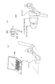
図4は、携帯用のメディアプレーヤ20等の音楽再生機器に接続して用いるノイズキャンセリングヘッドホン(NCヘッドフォン)10を模式的に示している。
メディアプレーヤ20は、内部の記録媒体に記録された音楽等のデータを再生し、L、Rの2チャンネル音声信号を、接続されたNCヘッドフォン10に出力する。
<2. Embodiment applied to NC headphones>
[2-1: Configuration of NC headphones]
FIG. 4 schematically shows a noise canceling headphone (NC headphone) 10 used by connecting to a music playback device such as a
The
NCヘッドフォン10は、ヘッドホン部11とノイズキャンセルユニット14から成る。
ヘッドホン部11は、ユーザの左右両耳に対応した各スピーカハウジング内にLチャンネルとRチャンネルのスピーカ13L、13Rを有する。
この例の場合、いわゆるフィードフォワード方式のノイズキャンセル処理を行うものとしており、マイク12L、12Rが、左右の各スピーカハウジングの外部音声を集音するように設けられている。
The NC headphone 10 includes a headphone unit 11 and a noise cancellation unit 14.
The headphone unit 11 includes L-channel and R-
In this example, so-called feedforward noise cancellation processing is performed, and the
なおヘッドホン部11は、図のようなスピーカハウジングを有するタイプでなく、図2(b)に示したイヤホン型や、耳当て型のようなタイプでもよい。本例の場合は、いずれにしてもマイク12L、12Rが設けられていればよい。
またフィードフォワード方式のノイズキャンセル処理を行うNCヘッドフォン10に限られず、フィードバック方式のノイズキャンセル処理を行うものでもよい。
The headphone section 11 is not limited to the type having the speaker housing as shown in the figure, but may be the type such as the earphone type or the ear pad type shown in FIG. In the case of this example, the
Further, the present invention is not limited to the NC headphone 10 that performs the feedforward type noise canceling process, and may perform the feedback type noise canceling process.
上記のようにマイク12L、12Rが設けられたヘッドホン部11に対してノイズキャンセルユニット14が接続される。
ノイズキャンセルユニット14は、メディアプレーヤ20から供給されてくる再生音楽等の音声信号に対してノイズ低減音声信号をミックスすることで、外部ノイズの低減された音声信号をスピーカ13L、13Rから出力させるものである。
簡単に言えば次のようにノイズ低減を行う。
スピーカハウジングに取り付けられたマイク12L、12Rは、スピーカハウジングを介してユーザの耳に達する外部ノイズを集音する。ノイズキャンセルユニット14は、このマイク12L、12Rで集音した外部ノイズの音声信号から、外部ノイズとは音響的に逆相のノイズ低減音声信号を生成する。そして生成したノイズ低減音声信号を、再生音楽等の音声信号に合成してスピーカ13L、13Rに供給する。
従ってスピーカ13L、13Rから出力される音声には、外部ノイズの逆相成分が含まれているため、この逆相成分と、実際にスピーカハウジングを介して漏れ込む外部ノイズとが空間的に相殺されることになり、ユーザの聴覚には外部ノイズ成分が低減されて本来の再生音楽の出力音声が届くものとなる。
The noise cancellation unit 14 is connected to the headphone unit 11 provided with the
The noise cancellation unit 14 mixes a noise-reduced audio signal with an audio signal such as reproduced music supplied from the
In short, noise reduction is performed as follows.
Therefore, since the sound output from the
ノイズキャンセルユニット14の内部構成例を図5に示す。
ノイズキャンセルユニット14は、マイクアンプ31L、31R、A/D変換器32L、32R、DSPまたはCPUによる主処理部33、メモリ部40、パワーアンプ42L、42R、A/D変換器41L、41Rを有する。
主処理部33には、ノイズキャンセル部34,ゲイン部35、加算器36L、36R、摺動操作検知部37、制御部38、イコライザ39が設けられる。
An example of the internal configuration of the noise cancellation unit 14 is shown in FIG.
The noise canceling unit 14 includes
The
まずメディアプレーヤ20からの再生音楽等の音声信号は次のように処理される。
メディアプレーヤ20からは、いわゆるヘッドホン出力としてのLチャンネル、Rチャンネルの再生音声信号SA−L,SA−Rが供給される。
この再生音声信号SA−L,SA−Rは、A/D変換器41L、41Rでデジタル信号化される。そしてイコライザ39で振幅−周波数特性補正や位相−周波数特性補正、あるいはその両方などの音質補正がなされる。
イコライザ39の補正処理は制御部38からの制御信号SG3に基づいて実行される。例えば周波数特性の指示などが制御信号SG3によってなされる。
First, an audio signal such as reproduced music from the
The
The reproduced audio signals SA-L and SA-R are converted into digital signals by A /
The correction process of the
イコライザ39で音質補正された再生音声信号SA−L,SA−Rは、それぞれ加算器36L、36Rでノイズ低減音声信号と加算されたうえで、パワーアンプ42L、42Rに供給される。
パワーアンプ42L、42Rはデジタルアンプで構成されても良いし、D/A変換器とアナログアンプで構成されても良い。
そしてパワーアンプ42L、42Rからの出力が、スピーカ13L、13Rに対する駆動信号とされ、スピーカ13L、13Rから再生音声信号SA−L,SA−Rに基づく音声出力が行われる。
The reproduced audio signals SA-L and SA-R whose sound quality has been corrected by the
The
Outputs from the
一方、上述のノイズキャンセルのための処理が次のように行われる。
マイク12L、12Rで集音された音声信号SmL,SmRは、ノイズキャンセルユニット14におけるマイクアンプ31L、31Rで増幅された後、A/D変換器32L、32Rでデジタル信号化される。
A/D変換器32L、32Rから出力されるデジタル化された音声信号SmL,SmRは、ノイズキャンセル部34に供給される。ノイズキャンセル部34は上述したフィードフォワード方式でのノイズ低減音声信号を生成するデジタルフィルタとされる。このノイズキャンセル部34は、制御部38から制御信号SG1で指示されるフィルタ係数で、音声信号SmL,SmRのそれぞれについてのフィルタ処理を行い、Lチャンネル及びRチャンネルのノイズ低減音声信号を生成する。
On the other hand, the processing for noise cancellation described above is performed as follows.
The audio signals SmL and SmR collected by the
The digitized audio signals SmL and SmR output from the A /
生成されたLチャンネル及びRチャンネルのノイズ低減音声信号はゲイン部35に供給される。ゲイン部35は、制御部38からの制御信号SG2で指示されるゲイン係数により、Lチャンネル及びRチャンネルのノイズ低減音声信号に対するゲインを与える。
そしてゲイン部35からのLチャンネル及びRチャンネルのノイズ低減音声信号は加算器36L、36Rに供給される、上述のように再生音声信号SA−L,SA−Rとそれぞれ加算される。
このようなノイズ低減音声信号が加算された再生音声信号SA−L,SA−Rにより、スピーカ13L、13Rから再生音声が出力されることで、上述のようなノイズ低減機能が発揮される。
The generated L-channel and R-channel noise-reduced audio signals are supplied to the
The L channel and R channel noise-reduced audio signals from the
The reproduced sound is output from the
本例のノイズキャンセルユニット14は、さらにマイク12L、12R又はその周辺の摺動操作によるユーザ操作を検知する機能を備える。
マイク12L、12Rで集音された音声信号SmL,SmRは、摺動操作検知部37にも供給される。
摺動操作検知部37の構成及び動作は詳しく後述するが、摺動操作検知部37では、時間軸のみの処理でユーザのマイク12L、12R又はその周辺への摺動操作を検知する。具体的には、入力された音声信号SmL,SmRにおける摺動音声信号成分のエネルギーレベルが第1の時間以上継続して所定値を越えている状態となったら、摺動操作の開始と判断する。そしてユーザの操作入力の開始を通知するため、摺動開始検知信号SdetSを制御部38に出力する。
また摺動操作検知部37は、摺動操作開始後は、摺動音声信号成分のエネルギーレベルが第2の時間以上継続して所定値未満となったら、摺動操作の終了と判断する。そしてユーザの操作入力の終了を通知するため、摺動終了検知信号SdetEを制御部38に出力する。
The noise cancellation unit 14 of this example further has a function of detecting a user operation due to a sliding operation of the
The audio signals SmL and SmR collected by the
Although the configuration and operation of the sliding
In addition, after the sliding operation is started, the sliding
制御部38は、上記の制御信号SG1,SG2,SG3によりノイズキャンセルユニット14の各部を制御する。またメディアプレーヤ20に対して制御信号SG4を送信することもできる。
特に本例では、制御部38はユーザの摺動操作に対応して制御処理を行う機能を備える。即ち制御部38は、摺動開始検知信号SdetS、摺動終了検知信号SdetEによって把握される摺動操作が実行されている期間、摺動操作について設定された所定の制御処理を行う。例えば摺動操作入力による操作の検知に応じて、制御信号SG4としてメディアプレーヤ20へ操作入力情報を送信することなどを行う。
メモリ部40は、制御部38が制御処理において参照する情報が記憶されている。例えばメモリ部40には、ノイズキャンセル部34やイコライザ39におけるフィルタ係数の情報等が記憶されている。
The
In particular, in this example, the
The
本実施の形態では、ユーザの摺動操作に応じて制御部38が所定の制御を行うが、その制御処理としては、リアルタイムで継続的な制御が適する。そのような制御の例として次のようなものが想定される。
In the present embodiment, the
まず制御信号SG4としてメディアプレーヤ20へコマンドを送信し、次のような動作を実行させることが考えられる。
例えば、
− 摺動操作期間中、ユーザの希望する再生位置まで、音を聞きながらFF(早送り)/REW(早戻し)の制御。
− 摺動操作期間中だけ再生オフ、ノイズキャンセルオフの制御(すぐに終わる会話などをしたい時に適した状態とする制御)。
− 摺動操作期間中だけノイズキャンセル機能をオフして環境音を聞き取りやすくする動作の制御。
− 摺動操作期間を操作量として、ユーザの希望するボリューム位置まで、音量アップまたは音量ダウンさせる制御。
− 摺動操作期間を操作量として、ユーザの希望する再生スピードまで、再生速度アップまたは再生速度ダウンの制御。
− 摺動操作期間を操作量として、ユーザの希望する再生ピッチまで、再生ピッチをアップまたはダウンさせる制御。
− 摺動操作期間中、音楽又はビデオ等の複数のコンテンツを順次、部分的に再生させる制御。即ちユーザが部分的に視聴しながらコンテンツを順番に検索できるようにし、摺動操作を止めた時点のコンテンツを再生させるような動作の制御。
などがあげられる。
First, it is conceivable that a command is transmitted to the
For example,
-Control of FF (fast forward) / REW (fast reverse) while listening to the sound to the playback position desired by the user during the sliding operation period.
-Playback off and noise cancellation off control only during the sliding operation period (control to make it suitable for a conversation that ends immediately).
-Control the operation to make it easier to hear the environmental sound by turning off the noise cancellation function only during the sliding operation period.
-Control to increase or decrease the volume to the volume position desired by the user using the sliding operation period as the operation amount.
-Control the playback speed up or playback speed down to the playback speed desired by the user using the sliding operation period as the operation amount.
-Control that raises or lowers the playback pitch up to the playback pitch desired by the user using the sliding operation period as the operation amount.
-Control that a plurality of contents such as music or video are sequentially and partially reproduced during the sliding operation. In other words, the operation is controlled such that the user can search the contents in order while partially viewing and reproduce the contents when the sliding operation is stopped.
Etc.
例えば摺動操作をメディアプレーヤ20の動作に関する操作とする場合、制御部38は摺動操作検知部37によって検知される摺動操作期間に、メディアプレーヤ20に所要のコマンドを送信するという処理を行うことになる。
また後述するが、マイク12Lの摺動操作とマイク12Rの摺動操作を区別して検知する場合は、2種類の操作内容を割り当てることができる。その場合、例えばマイク12Lの摺動操作をボリュームアップ、マイク12Rの摺動操作をボリュームダウンとすれば、制御部38は摺動操作検知部37による摺動操作の検知に応じて、メディアプレーヤ20に「ボリュームアップ」又は「ボリュームダウン」のコマンドを送信する処理を行うこととなる。
さらに、後述するが、摺動方向や摺動箇所などで操作を区別することも可能であり、またそれらと左右マイク12L、12Rの組み合わせなどで、多様な操作を区別して設定することもできる。その場合も、制御部38はそれらの摺動操作の検知に応じて、所定のコマンドをメディアプレーヤ20に送信する。
For example, when the sliding operation is an operation related to the operation of the
As will be described later, when the sliding operation of the
Further, as will be described later, it is possible to distinguish the operations according to the sliding direction, the sliding location, and the like, and various operations can be distinguished and set by combining them with the left and
ノイズキャンセル機能を実現するためには、より耳元位置に近いマイク12L、12Rを」設置することが必要なため、通常マイク12L、12Rは、耳元に設置されている。すると、例えば通勤時などにメディアプレーヤ20の本体を取り出さなくても、マイク12L、12Rを摺動操作するだけで、メディアプレーヤ20の動作の制御が可能になるのは、ユーザにとって大きな利便性がある。
In order to realize the noise canceling function, it is necessary to install the
また制御部38が、摺動操作検知に応じて、ノイズキャンセルユニット14の内部制御を行う例も考えられる。
例えば摺動操作に応じて、制御信号SG1による制御でノイズキャンセル部34のフィルタ係数の切り替えを行うようにしても良い。例えば摺動操作期間にフィルタ係数を短時間単位で切り替えていき、ユーザが現状に適したフィルタ特性を選択できるような動作の制御も可能である。
一般的に、ノイズ環境特性は、周波数特性で観察したとしても、飛行場、駅のプラットホーム、電車内、工場などの場所の環境によって大きく異なっている。したがって、ノイズ低減のためのフィルタ特性は、本来は、各ノイズ環境特性に合わせた最適なものを用いることが望まれる。そのため、ユーザがマイク12L、12Rの摺動操作によって、最も適したフィルタ特性を切り替えて選んでいけるようにすることは有用である。
An example in which the
For example, the filter coefficient of the
In general, even if the noise environment characteristics are observed with frequency characteristics, they are greatly different depending on the environment of the place such as an airfield, a station platform, a train, a factory, and the like. Therefore, it is originally desirable to use an optimum filter characteristic for noise reduction according to each noise environment characteristic. Therefore, it is useful for the user to switch and select the most suitable filter characteristic by sliding operation of the
また制御部38が、摺動操作に応じて、制御信号SG2よる制御でゲイン部35のゲイン係数の切り替えを行うようにしても良い。これによってユーザは、ノイズキャンセルのレベルを、容易な操作で任意に調整できることになる。
Further, the
また制御部38が、摺動操作検知に応じて、制御信号SG3よる制御でイコライザ39におけるフィルタ係数の変更を行うようにしても良い。例えば摺動操作期間にイコライジング特性を短時間単位で切り替えていき、ユーザが好みの特性を選択できるような動作の制御も可能である。これによってユーザは、容易な操作で音質補正状態を選択できる。例えばプリセットとして各種周波数特性をメモリ部40に記憶させておき、ユーザが好みの音質となるイコライザ特性を、順次適用し、摺動操作の終了で選択できるようにすることは有用である。
Further, the
[2−2:摺動操作検知部(構成例I)]
以下、摺動操作検知部37の構成及び動作を説明する。ここではまず図6に示す構成例Iについて説明する。
この構成例Iは、マイク12L、12Rからの音声信号SmL,SmRについて共通に摺動操作を検知する構成例である。
摺動操作検知部37は、加算器51,ローパスフィルタ52、絶対値化回路53、ローパスフィルタ54、判定処理部55を備える。
[2-2: Sliding operation detection unit (Configuration Example I)]
Hereinafter, the configuration and operation of the sliding
This configuration example I is a configuration example in which a sliding operation is detected in common for the audio signals SmL and SmR from the
The sliding
マイク12L、12Rからの各音声信号SmL,SmRは、加算器51で加算されてローパスフィルタ52に入力される。ローパスフィルタ52はカットオフ周波数がfc1とされている。このカットオフ周波数fc1は、摺動音声信号成分を抽出するための周波数に設定される。マイク12L、12Rが、例えば樹脂成型されたヘッドホンハウジングに取り付けられている場合、その樹脂材料を指で擦ったときの音声信号成分が抽出できるカットオフ周波数が設定される。従って、樹脂の種類によって好適なカットオフ周波数fc1が決められる。もちろんマイク12L、12Rの周囲に金属材料等その他の材料の部材が用いられる場合もある。そのためマイク12L、12R自体の材料や周囲の材料に応じたフィルタ特性となる。
The audio signals SmL and SmR from the
摺動操作時には、音声信号SmL又はSmRにおいてマイク近辺で発生する摺動音が圧倒的に大きい。ただし音声信号SmL,SmRには暗騒音や周囲ノイズなど帯域の広いノイズも含んでいる。そこでまずローパスフィルタ52で摺動音声信号成分を抽出する。
一般に、摺動によって発生する音の音声信号成分は低域に高いエネルギーを持つため、ローパスフィルタ52で摺動音声信号成分を抽出することが考えられるが、材質によっては所定の通過帯域を持つバンドパスフィルタを用いる場合も考えられる。
いずれにしても、まず、摺動音声信号成分のエネルギーレベルが高い周波数帯域が抽出されればよい。
During the sliding operation, the sliding sound generated in the vicinity of the microphone in the audio signal SmL or SmR is overwhelmingly large. However, the audio signals SmL and SmR include wide-band noise such as background noise and ambient noise. Therefore, the sliding sound signal component is first extracted by the low-
In general, since the sound signal component of the sound generated by sliding has high energy in the low range, it is conceivable that the sliding sound signal component is extracted by the low-
In any case, first, a frequency band in which the energy level of the sliding sound signal component is high may be extracted.
ローパスフィルタ52から出力される音声信号SmL,SmRの加算信号についての摺動音声信号成分は絶対値化回路53で絶対値化される。
絶対値化回路53で絶対値化された信号S0はローパスフィルタ54を介して、音声信号SmL,SmRのエネルギーレベルを表した信号Sとされて判定処理部55に入力される。ローパスフィルタ54のカットオフ周波数fc2は、信号S0を包絡線信号化するための周波数に設定される。
判定処理部では信号Sについて後述する処理で摺動操作の開始、終了を検知する。そして検知の結果、摺動開始検知信号SdetS、摺動終了検知信号SdetEを制御部38に出力する。
The sliding sound signal component of the sum signal of the sound signals SmL and SmR output from the low-
The signal S0 that has been converted to an absolute value by the absolute
The determination processing unit detects the start and end of the sliding operation in a process described later for the signal S. As a result of the detection, a sliding start detection signal SdetS and a sliding end detection signal SdetE are output to the
このような摺動操作検知部37の動作を図7〜図9で説明する。
図7は、摺動操作があったときの信号S0,信号Sの波形の例を示している。
上述したようにローパスフィルタ52は、摺動音声信号成分を抽出する。このローパスフィルタ52の出力は、摺動音声信号成分であるが、正/負の値を持つ振幅であるため、負の振幅もエネルギーレベルとして判断するために絶対値化回路53で絶対値化された信号S0とする。
摺動操作期間中は、図のように信号S0のエネルギーレベル(絶対値化された摺動音声信号成分の振幅レベル)が高くなる。
ただし、ユーザの摺動操作は不安定であり、必ずしも一定の速度及び強さで擦られるものではなく、そのため振幅は微少な時間で変動する。
これをローパスフィルタ54でエンベロープ化した信号Sとすることで、摺動操作期間として、高いエネルギーレベルの継続する期間を判定しやすいものとすることができる。
判定処理部55では、この信号Sから、図示する摺動操作期間、つまり制御対象に対して摺動操作に応じた機能の制御を行う期間を判定する。
Illustrating the operation of the sliding
FIG. 7 shows an example of waveforms of the signals S0 and S when there is a sliding operation.
As described above, the low-
During the sliding operation period, as shown in the figure, the energy level of the signal S0 (the amplitude level of the sliding audio signal component converted into an absolute value) becomes high.
However, the user's sliding operation is unstable and is not necessarily rubbed at a constant speed and strength, and therefore the amplitude fluctuates in a minute time.
By using this as the signal S enveloped by the low-
The
図8は判定処理部55が信号Sから、摺動操作の開始と終了を検知する処理のフローチャートを示している。
判定処理部55は入力される信号Sに対して図8の摺動操作判定処理を行う。
まずステップF101で判定処理部55は、信号Sのレベルが閾値TH1より高いか否かを判断する。
図9には信号Sの波形と閾値TH1、TH2を示している。閾値TH1は、信号Sのエネルギーレベルが増大したか否かを判断する閾値である。一方、閾値TH2は、信号Sのエネルギーレベルが減少したか否かを判断する閾値である。
FIG. 8 shows a flowchart of processing in which the
The
First, in step F101, the
FIG. 9 shows the waveform of the signal S and threshold values TH1 and TH2. The threshold value TH1 is a threshold value for determining whether or not the energy level of the signal S has increased. On the other hand, the threshold value TH2 is a threshold value for determining whether or not the energy level of the signal S has decreased.
ステップF101では、入力される信号Sの値を逐次閾値TH1と比較していく。信号Sが閾値TH1以下であると判断されたときは、「R」で示すようにステップF101に戻り、次の信号Sの入力値と閾値TH1の比較を行う。
信号Sが閾値TH1を越えたときに判定処理部55はステップF102に進む。
ステップF102では判定処理部55は、まずカウンタCn1を0にリセットし、カウントをスタートさせる。
そして判定処理部55はステップF103でカウンタCn1をインクリメントしていきながら、ステップF104,F105の判断を行っていく。
In step F101, the value of the input signal S is sequentially compared with the threshold value TH1. When it is determined that the signal S is equal to or less than the threshold value TH1, the process returns to step F101 as indicated by “R”, and the input value of the next signal S is compared with the threshold value TH1.
When the signal S exceeds the threshold value TH1, the
In step F102, the
Then, the
ステップF104では判定処理部55は、信号Sが閾値TH1より大きいか否かを判断する。
また、ステップF105では、カウンタCn1の値が、第1の時間THtm1に達したかどうかを判断する。
第1の時間THtm1とは、図9に示すような所定時間である。これは、信号Sのエネルギー増大が瞬間的に起こったのではなく、摺動操作に伴う継続的なエネルギーレベルの増大であると判断するための時間として設定される。
もしステップF104で信号Sが閾値TH1より低いことが検出された場合は、ステップF101で検出したエネルギーレベルの増大は瞬間的なものであり、摺動操作によるものではないと判断して、「R」で示すようにステップF101に戻る。つまり摺動操作が開始されたのではないと判断する。
一方、ステップF105でカウンタCn1の値が第1の時間THtm1に達した場合とは、信号Sのエネルギーレベルが閾値TH1より大きい状態が継続したと判断される場合となる。
このとき判定処理部55はステップF106に進み、摺動操作が開始されたと判定する。そして制御部38に対して摺動開始検知信号SdetSを出力する。
In step F104, the
In step F105, it is determined whether or not the value of the counter Cn1 has reached the first time THtm1.
The first time THtm1 is a predetermined time as shown in FIG. This is set as a time for determining that the increase in energy of the signal S does not occur instantaneously but is a continuous increase in energy level accompanying the sliding operation.
If it is detected in step F104 that the signal S is lower than the threshold value TH1, it is determined that the increase in the energy level detected in step F101 is instantaneous and not due to the sliding operation. As shown in FIG. That is, it is determined that the sliding operation has not started.
On the other hand, when the value of the counter Cn1 reaches the first time THtm1 in step F105, it is determined that the state where the energy level of the signal S is greater than the threshold value TH1 has continued.
At this time, the
摺動操作開始と判定した後は、判定処理部55はステップF107に進み、摺動操作の終了判定を開始する。
まずステップF107では、信号Sを閾値TH2と比較し、閾値TH2未満となったか否かを判別する。
図9に示すように、例えば閾値TH2は、閾値TH1より多少低いレベルに設定されている。この閾値TH2は、信号Sのエネルギーレベルの低下を判定するための値である。
After determining that the sliding operation has started, the
First, in step F107, the signal S is compared with a threshold value TH2, and it is determined whether or not it is less than the threshold value TH2.
As shown in FIG. 9, for example, the threshold value TH2 is set to a level slightly lower than the threshold value TH1. This threshold value TH2 is a value for determining a decrease in the energy level of the signal S.
信号Sが閾値TH2より小さくなった場合は、判定処理部55は、摺動操作が終了された可能性があるとして、ステップF108に進む。
ステップF108で判定処理部55はカウンタCn2を0にリセットし、カウントをスタートさせる。
そして判定処理部55はステップF109でカウンタCn2をインクリメントしていきながら、ステップF110,F111の判断を行っていく。
When the signal S becomes smaller than the threshold value TH2, the
In step F108, the
Then, the
ステップF110では判定処理部55は、信号Sが閾値TH2未満となっているか否かを判断する。
また、ステップF111では、カウンタCn2の値が、第2の時間THtm2に達したかどうかを判断する。
第2の時間THtm2とは、図9に示すような所定時間である。これは、信号Sのエネルギー減少が瞬間的に起こったのではなく、摺動操作の終了に伴う継続的なエネルギーレベルの低下であると判断するための時間として設定される。
In step F110, the
In Step F111, it is determined whether the value of the counter Cn2 has reached the second time THtm2.
The second time THtm2 is a predetermined time as shown in FIG. This is set as a time for determining that the energy decrease of the signal S does not occur instantaneously, but is a continuous energy level decrease accompanying the end of the sliding operation.
もしステップF110で信号Sが閾値TH2より低くなっていないことが検出された場合は、ステップF107で検出したエネルギーレベルの低下は瞬間的なものであり、摺動操作の終了によるものではないと判断して、「Q」で示すようにステップF107に戻る。つまり摺動操作が終了されたのではないと判断する。
例えば図9には、摺動開始後、期間tmAとして、一時的に信号Sのエネルギーレベルが閾値TH2より低下した状態を示している。この場合、期間tmAは第2の時間THtm2より短い期間である。このような場合は、摺動操作中の一時的なレベル低下とする。
ユーザによる摺動操作は必ずしも規則的な摺動ではなく、先に述べたように固定の強さで一定の速度の摺動となるわけではない。また摺動時の指の引っかかりなどで、瞬間的に摺動が停止することも通常に発生する。
このため、信号Sのエネルギーレベルの低下がみられたときに直ぐに摺動操作が終了されたと判断することは適切でなく、そのため第2の時間THtm2を設定し、低下した期間が第2の時間THtm2未満であれば、摺動操作は終わっていないとするものである。
If it is detected in step F110 that the signal S is not lower than the threshold value TH2 , it is determined that the decrease in the energy level detected in step F107 is instantaneous and not due to the end of the sliding operation. Then, as indicated by “Q”, the process returns to Step F107. That is, it is determined that the sliding operation is not finished.
For example, FIG. 9 shows a state in which the energy level of the signal S has temporarily decreased below the threshold value TH2 as the period tmA after the start of sliding. In this case, the period tmA is shorter than the second time THtm2. In such a case, the level is temporarily lowered during the sliding operation.
The sliding operation by the user is not necessarily a regular sliding operation, and as described above, the sliding operation is not a constant speed with a fixed strength. Also, it is normal for the sliding to stop instantaneously due to a finger caught during sliding.
For this reason, it is not appropriate to determine that the sliding operation has been completed immediately when the energy level of the signal S is decreased. Therefore, the second time THtm2 is set, and the decreased period is the second time. If it is less than THtm2, the sliding operation is not finished.
一方、ステップF111でカウンタCn2の値が第2の時間THtm2に達した場合とは、信号Sのエネルギーレベルが閾値TH2より小さい状態が継続したと判断される場合となる。
このとき判定処理部55はステップF112に進み、摺動操作が終了されたと判定する。そして制御部38に対して摺動終了検知信号SdetEを出力する。
例えば図9では、2回目に信号Sのエネルギーレベルが閾値TH2より低下した後は、エネルギーレベルが低下した状態が第2の時間THtm2以上継続している。その場合、摺動操作の終了と判定される。
On the other hand, the case where the value of the counter Cn2 reaches the second time THtm2 in Step F111 is a case where it is determined that the state where the energy level of the signal S is smaller than the threshold value TH2 has continued.
At this time, the
For example, in FIG. 9, after the energy level of the signal S has decreased below the threshold value TH2 for the second time, the state in which the energy level has decreased continues for the second time THtm2 or more. In that case, it is determined that the sliding operation is finished.
本例の摺動操作検知部37は、判定処理部55が以上の図8のように摺動操作の開始、終了の判定処理を行う。これにより制御部38は摺動操作がなされている期間を認識できるため、継続的な操作又は操作量を指定する操作としての摺動操作に基づく制御が可能となる。
In the sliding
また摺動操作検知部37は、判定処理部55が時間軸でのエネルギーレベルの増減を観測して摺動操作の開始、終了の判定処理を行う。これによってリソースの増加を招くことなく、容易に摺動操作を判定できる。
摺動操作があった場合、マイクロホン入力信号における所定帯域の音声信号(摺動音声信号成分)のエネルギーレベル(振幅)が大きくなる。そこで摺動音声信号成分のエネルギーを監視することで、波形解析等を行わず、エネルギー増減判定で摺動操作を検知することができる。
これによって操作検知のための処理負担の軽減、それによる低コスト化の促進が可能となる。特にNCヘッドフォン10のノイズキャンセルユニット14のように小型でリソースの小さい機器において、このように簡易な動作で必要な検知処理が可能となることは、非常に有効である。
また操作入力の検知処理は、不定期のユーザ操作に対応するために常に実行していなければならない。このため時間軸の信号処理として計算量の小さい処理であることで、常に実行していく処理として適している。
さらに簡易な処理であることで摺動操作の開始や終了の検知時間が短縮されレスポンスの良い装置動作が可能となる。
Further, in the sliding
When there is a sliding operation, the energy level (amplitude) of a predetermined band audio signal (sliding audio signal component) in the microphone input signal increases. Therefore, by monitoring the energy of the sliding audio signal component, it is possible to detect a sliding operation by energy increase / decrease determination without performing waveform analysis or the like.
As a result, it is possible to reduce the processing load for detecting the operation and thereby promote cost reduction. In particular, it is very effective that necessary detection processing can be performed with such a simple operation in a small-sized device with a small resource such as the noise canceling unit 14 of the NC headphone 10.
Further, the operation input detection process must always be executed in order to cope with irregular user operations. For this reason, the processing with a small amount of calculation as the time-axis signal processing is suitable as a processing that is always executed.
Furthermore, the simple process enables the detection time of the start and end of the sliding operation to be shortened, and the device operation with good response becomes possible.
また本例の場合は、瞬間的な摺動の停止等で瞬間的に信号Sのエネルギーレベルの低下があっても即座に摺動操作の終了とはしない。
例えば摺動中に指が多少休むことや不定期なノイズの混入などにより、極一時的にエネルギーレベルが下がっても、次にすぐにエネルギーレベルが大きくなるのであれば、摺動操作は継続されていると判断する。
これにより、ユーザ操作の検知として好適かつユーザの意志に沿った操作終了検知ができる。つまり、ユーザは丁寧な摺動をすることに、さほど気を遣わなくてもよく操作が容易である。
Further, in the case of this example, even if the energy level of the signal S is instantaneously decreased due to an instantaneous stoppage of sliding, the sliding operation is not immediately terminated.
For example, even if the energy level drops extremely temporarily due to some rest of the finger during sliding or irregular noise, the sliding operation is continued if the energy level immediately increases. Judge that
Thereby, it is possible to detect the end of the operation suitable for detecting the user operation and in accordance with the user's will. In other words, the user does not have to pay much attention to the careful sliding, and the operation is easy.
また、図5に示した構成例Iによれば、ユーザは左右のマイク12L、12Rのどちらに対して摺動操作を行っても良い。
例えば鞄などを持って片方の手がふさがっているときに、空いている手で摺動操作を行うことが容易となり、操作性が良いものとすることができる。
Further, according to the configuration example I shown in FIG. 5, the user may perform a sliding operation on either of the left and
For example, when one hand is blocked by holding a bag or the like, it is easy to perform a sliding operation with a free hand, and the operability can be improved.
そして摺動操作検知部37がこのように摺動操作を検知することに応じて、制御部38は当該摺動操作に割り当てられた操作内容に応じた制御、例えば先に例示した制御を行う。
制御部38がメディアプレーヤ20の動作を制御するコマンドを送信することとすれば、ユーザは通勤時などにメディアプレーヤ20をポケットや鞄にしまったまま操作ができる。
Then, in response to the sliding
If the
また指などで摺動するという操作手法であることで直観的にメディアプレーヤ20或いはノイズキャンセルユニット14のコントロールが可能となる。
また、マイク12L、12R又はその周辺を摺動する方式であるため、タッチセンサなど特殊なセンサを使わなくても通常の(安価な)マイクと、CPU/DSP等の信号処理部があれば実装できるため、コスト削減に役立つ。
さらに本例のNCヘッドフォン10の場合、ノイズキャンセル機能のためにヘッドホン部11にマイク12L、12Rが設けられている。このマイク12L、12Rを利用して摺動操作を可能とするものであるため、操作入力のための新たなセンサデバイスを設けることは不要であり、その点でもコスト削減に適しており、また装置構成部品の増大ということもない。
Further, the operation method of sliding with a finger or the like makes it possible to intuitively control the
In addition, since the
Furthermore, in the case of the NC headphone 10 of this example,
なお、図5の例ではL、Rチャンネルの各マイク12L、12Rからの音声信号SmL,SmRを合成して、摺動操作を判断したが、一方のチャンネルのみの音声信号(例えば音声信号SmL)のみをローパスフィルタ52に入力してもよい。その場合は、当該チャンネルのマイク12Lのみが摺動操作の用途に供される構成となる。
In the example of FIG. 5, the audio signals SmL and SmR from the
[2−3:摺動操作検知部(構成例II)]
構成例IIとしての摺動操作検知部37を図10で説明する。
この構成例IIは、LチャンネルとRチャンネル、即ちマイク12L、12Rを、それぞれ別の操作に割り当てることができるようにする例である。
例えばマイク12Lの摺動操作をボリュームアップ、マイク12Rの摺動操作をボリュームダウンなどとすることができるような構成例である。
[2-3: Sliding operation detection unit (Configuration Example II)]
A sliding
This configuration example II is an example in which the L channel and the R channel, that is, the
For example, the configuration is such that the sliding operation of the
図10に示すように、摺動操作検知部37には、LチャンネルとRチャンネルで独立2系統の摺動操作検知構成を採る。
即ちマイク12Lからの音声信号SmLに対して、ローパスフィルタ52L、絶対値化回路53L、ローパスフィルタ54L、判定処理部55Lを設ける。またマイク12Rからの音声信号SmRに対して、ローパスフィルタ52R、絶対値化回路53R、ローパスフィルタ54R、判定処理部55Rを設ける。
As shown in FIG. 10, the sliding
That is, a low-
ローパスフィルタ52L、52R、絶対値化回路53L、53R、ローパスフィルタ54L、54Rの動作は上記構成例Iのローパスフィルタ52、絶対値化回路53、ローパスフィルタ54の動作と同様であるため、繰り返しの説明は避ける。
また判定処理部55L、55Rは、それぞれが例えば図8のような摺動操作の開始、終了の判定処理を行えばよい。
そして判定処理部55Lは音声信号SmLから得られる信号Sについて摺動操作の開始を検知したら摺動開始検知信号SdetS(L)を制御部38に出力し、また摺動操作の終了を検知したら摺動終了検知信号SdetE(L)を制御部38に出力する。
また判定処理部55Rは音声信号SmRから得られる信号Sについて摺動操作の開始を検知したら摺動開始検知信号SdetS(R)を制御部38に出力し、また摺動操作の終了を検知したら摺動終了検知信号SdetE(R)を制御部38に出力する。
The operations of the low-
Further, each of the
The
The
制御部38は摺動開始検知信号SdetS(L)及び摺動終了検知信号SdetE(L)と、摺動開始検知信号SdetS(R)及び摺動終了検知信号SdetE(R)により、2種類の操作入力を認識できる。従って、それらに応じて例えば上記のボリュームアップ/ダウンの制御などを行うことができる。
The
このような構成例IIにより、左右のマイク12L、12Rで2種類の操作を使い分けることができ、ユーザの操作性向上に好適である。
According to such configuration example II, the left and
[2−4:摺動操作検知部(構成例III)]
続いて構成例IIIを図11に示す。これは上記構成例IIと同様に、LチャンネルとRチャンネル、即ちマイク12L、12Rを、それぞれ別の操作に割り当てることができるようにする例である。上記構成例IIの場合は、摺動操作検知部37に単純に2系統の摺動操作検知処理系を搭載するため、構成負担が大きくなる。この構成例IIIは構成負担を軽減できる例である。
この構成例IIIでは、摺動操作検知部37は、複数の各チャンネルの音声信号SmL,SmRのうちで摺動音声信号成分が含まれるチャンネルを判定するチャンネル判定処理と、複数チャンネルの摺動音声信号成分を加算または減算した音声信号についての摺動操作開始/終了の判定処理とを行う。これにより摺動操作の検知及び摺動操作が行われたチャンネルの検知を行うものである。
[2-4: Sliding operation detection unit (Configuration Example III)]
Subsequently, Configuration Example III is shown in FIG. This is an example in which the L channel and the R channel, that is, the
In the configuration example III, the sliding
この場合、図11に示すように、マイク12Lからの音声信号SmLはローパスフィルタ52Lに入力され、カットオフ周波数fc1で摺動音声信号成分が抽出される。
また、マイク12Rからの音声信号SmRはローパスフィルタ52Rに入力され、カットオフ周波数fc1で摺動音声信号成分が抽出される。
In this case, as shown in FIG. 11, the audio signal SmL from the
Also, the audio signal SmR from the
ローパスフィルタ52Lの出力は絶対値化回路56Lと減算器59に供給される。
またローパスフィルタ52Rの出力は絶対値化回路56Rと減算器59に供給される。
絶対値化回路56Lはローパスフィルタ52Lの出力を絶対値化して減算器57に供給する。絶対値化回路56Rはローパスフィルタ52Rの出力を絶対値化して減算器57に供給する。
従って減算器57の出力としては、左右チャンネルの音声信号SmL,SmRの各摺動音声信号成分のエネルギーレベルの差分が現れることになる。
この減算器57の出力はカットオフ周波数fc2のローパスフィルタ58で包絡線信号とされて判定処理部55に供給される。
判定処理部55では、マイク12L、12Rのいずれかに対して摺動操作がなされたときは、この包絡線信号の正負判定により、マイク12L、12Rのどちらに対する摺動操作であったかを検出できる。
The output of the low-
The output of the
The absolute
Therefore, as the output of the
The output of the
When the sliding operation is performed on either of the
ローパスフィルタ52L、52Rで抽出された音声信号SmL,SmRにおける各摺動音声信号成分は、減算器59で減算処理され、差分値が抽出される。
マイク12L、12Rのうちで一方が摺動操作された場合、その摺動操作された方の音声信号の摺動音声信号成分のエネルギーが増大するが、従って減算器59の出力としては、その摺動操作によるエネルギー増大成分が現れる。
この減算器59の出力は絶対値化回路53で絶対値化され、カットオフ周波数fc2のローパスフィルタ54で包絡線化された信号Sとされて判定処理部55に供給される。
Each sliding sound signal component in the sound signals SmL and SmR extracted by the low-
When one of the
The output of the
判定処理部55では、信号Sに対して摺動操作の判定処理を行い、信号Sについての判定処理に応じて摺動開始検知信号SdetS、摺動終了検知信号SdetE、及びLチャンネル/Rチャンネルの判定信号D−LRを制御部38に出力する。
The
この場合の判定処理部55の判定処理は、例えば図12のように行われればよい。
なお図12において、上記図8と同一の処理については同一のステップ番号を付し、重複説明は避ける。
この図12の処理では、ステップF101〜F106で、図8の場合と同様に摺動操作の開始の判定を行う。
そしてステップF106で摺動開始と判定した場合、判定処理部55は、ステップF130でL/R判定を行う。
即ち、この時点で図11のローパスフィルタ58からの信号の正負を判定する。図11のように減算器57でLチャンネルの絶対値化信号からRチャンネルの絶対値化信号が減算される構成の場合、ローパスフィルタ58からの信号が正であればLチャンネル、負であればRチャンネルと判定する。
このL/R判定は、マイク12L、12Rのどちらで摺動操作されたかを検出する処理となる。そして判定処理部55は、L/Rの判定結果を示すLチャンネル/Rチャンネルの判定信号D−LRを制御部38に出力する。
従って、摺動操作の開始が検知された場合、制御部38には、摺動開始検知信号SdetSと判定信号D−LRが供給されることとなる。
The determination process of the
In FIG. 12, the same steps as those in FIG. 8 are given the same step numbers, and redundant description is avoided.
In the process of FIG. 12, the start of the sliding operation is determined in steps F101 to F106 as in the case of FIG.
If it is determined in step F106 that the sliding has started, the
That is, at this time, the sign of the signal from the low-
This L / R determination is a process of detecting which of the
Therefore, when the start of the sliding operation is detected, the
続いて判定処理部55はステップF107〜F111で摺動操作の終了の判定を図8の場合と同様に行う。
そして摺動操作が終了されたと判定されたら、判定処理部55はステップF112で制御部38に対して摺動終了検知信号SdetEを出力する。
Subsequently, the
If it is determined that the sliding operation has been completed, the
この構成例IIIの場合、制御部38は摺動開始検知信号SdetS、摺動終了検知信号SdetE、及び判定信号D−LRにより、マイク12L、12Rを別個に用いた2種類の操作入力を認識でき、それらに応じて例えばボリュームアップ/ダウンなどの制御などを行うことができる。
In the case of the configuration example III, the
従ってこの構成例IIIによっても、左右のマイク12L、12Rで2種類の操作を使い分けることができ、ユーザの操作性向上に好適である。その上で構成例IIに比べて摺動操作検知部37の構成負担を少なくできる。特に判定処理部55が1つでよいことで処理(リソース)負担も軽減される。
なお、減算器59に代えて加算器を用いることも考えられる。
Therefore, according to the configuration example III, the left and
Note that an adder may be used instead of the
<3.摺動ガイドを備えた実施の形態>
続いてマイク側に摺動操作位置をガイドする摺動ガイドを備えた実施の形態について説明する。本発明のマイクロホン装置の実施の形態ともなるものである。
先に図2においてマイク4に対する摺動操作の態様について示したが、その場合は、摺動操作とは単にマイク4が形成された部位を擦るような操作であると述べた。
これに対し、図13にはマイク4の周辺に摺動ガイド8を設けた構成を示している。
<3. Embodiment provided with sliding guide>
Next, an embodiment provided with a sliding guide for guiding the sliding operation position on the microphone side will be described. This is also an embodiment of the microphone device of the present invention.
The mode of the sliding operation on the
On the other hand, FIG. 13 shows a configuration in which a sliding
図13(a)は図2(a)と同様にパーソナルコンピュータ100の筐体上の所定部位にマイク4が設けられている場合を示している。
この図13(a)の場合、マイク4の周囲にリング状の摺動ガイド8が形成されている。
図13(b)も図2(b)と同様に、例えばノイズキャンセルイング用にマイク4が設けられたヘッドホン(イヤホン)200の一部を示しているが、この場合もマイク4の周囲にリング状の摺動ガイド8が形成されている。
FIG. 13A shows a case where the
In the case of FIG. 13A, a ring-shaped sliding
Similarly to FIG. 2B, FIG. 13B shows a part of the headphone (earphone) 200 provided with the
摺動ガイド8は、単にユーザが触覚で認識できる構造部であればよく、例えば凸状又は凹状に形成されて、ユーザの指による摺動をガイドできるものとされる。つまりユーザが摺動ガイド8を意識して円形状に円滑に指などを動かせるものである目的で設置された構造物であればよい。
この図13(a)(b)の場合は、凹状、つまりリング状の溝がマイク4の周囲に形成されている例としているが、凸状(レール状)のリングとしてもよい。
The sliding
In the case of FIGS. 13A and 13B, a concave, that is, a ring-shaped groove is formed around the
先に、ユーザが摺動操作を周回状(円を描くように回す)に行うとすると、摺動操作が容易であると述べたが、例えばこのようにリング状の摺動ガイド8を設ければ、ユーザはさらに容易に周回状の摺動操作を行うことができる。即ちユーザは指先で摺動ガイド8に触れながら、指を回すようにしていくと、それが摺動操作となる。
そして摺動ガイド8に案内されながらユーザが周回状の摺動操作を行うことによれば、比較的長い時間摺動操作を続けるといったことも容易となる。
また摺動ガイド8を設けることによって、ユーザの摺動操作がマイク4から離れた位置で行われて適切に操作判定ができなかったり、ユーザがどのあたりを摺動すればよいかがわからなくなるといったこともなくなる。
Previously, it was described that the sliding operation is easy if the user performs the sliding operation in a circular manner (turning so as to draw a circle). For example, a ring-shaped sliding
Then, if the user performs a circular sliding operation while being guided by the sliding
Further, by providing the sliding
なお、ここでは周回状の摺動操作をガイドするリング状の摺動ガイド8を例示したが、摺動ガイド8は直線状、湾曲状などでもよい。また一部が切り欠かれたリング状や直線状などであってもよい。
Although the ring-shaped sliding
<4.有方向音源部を備えた実施の形態>
さらにマイクロホン装置の実施の形態として、図14にマイク4の周辺に摺動操作方向によって異なる音声信号成分を生じさせる有方向音源部9を備えた例を説明する。
図14(a)(b)も、図2,図13と同様にパーソナルコンピュータ100やヘッドホン200での例を示しているが、これらにおいてマイク4の周囲が、有方向音源部9とされている。
<4. Embodiment with Directional Sound Source>
Furthermore, as an embodiment of the microphone device, an example will be described in which a directional
FIGS. 14A and 14B also show examples of the
有方向音源部9とは、摺動方向に応じて発する音が異なる材料又は構造とされた部分である。
有方向音源部9の一例を図15に挙げる。例えば図15(a)では相互接触で音が鳴るような材質のもの、繊維状、根はばね性質を持つものを示している。これは、このような性質を持つ材料であっても良いし、型などで作った構造物でもかまわない。
この場合、例えば図15(b)のように、右側に摺動操作すれば相互接触しやすく、音が発生しやすいが、図15(c)のように左側へ摺動操作する場合には、相互接触しないため音が発生しにくいという性質があるものとされる。
つまり摺動操作方向によって発生する音の周波数特性が異なる。この両者の音の違いを検出することで、方向別に異なる制御処理を行うことができる。
The directional
An example of the directional
In this case, for example, as shown in FIG. 15 (b), if the sliding operation is performed on the right side, it is easy to come into contact with each other, and a sound is likely to be generated. It is said that there is a property that it is difficult to generate sound because they do not contact each other.
That is, the frequency characteristics of the sound generated vary depending on the sliding operation direction. By detecting the difference between the two sounds, different control processes can be performed for each direction.
有方向音源部9の例として、豚毛など毛状のもの、ナイロン・ポリプロピレン・ポリオレフィン・ABS・ガラス繊維・FRPなどで糸または繊維状に編んだもの、また毛、絹に限らず、綿やレーヨン、アセテートなどでできたベルベットやベロア繊維など織物の両面を毛羽立てた布地加工した物質などを材料とする例が考えられる。
また金属、ゴム、樹脂等の材料やそれらの組み合わせで作った構造物でも、構造形状により異なる方向で触れたときに異なる音が出るようにすることができ、有方向音源部9とすることができる。
Examples of the directional
In addition, even a structure made of metal, rubber, resin, or the like or a combination thereof can be made to produce different sounds when touched in different directions depending on the structure shape. it can.
上記図15は一方向とその逆方向の摺動の場合の例で挙げたが、摺動方向によって音が異なる材質や構造は以上のように多様に考えられる。
もちろん音が異なることとなる摺動方向も図15のように往路、復路で異なる場合だけでなく、X方向と、それに直交するY方向で音が異なるようにすることも可能である。さらには、X方向、Y方向、斜め方向で音が異なるようにすることも可能である。
またさらに、図20(a)に示すように、X方向順方向(X1)、X方向逆方向(X2)、Y方向順方向(Y1)、Y方向逆方向(Y2)で音が異なるようにすることも可能である。
FIG. 15 shows an example in the case of sliding in one direction and the opposite direction, but various materials and structures with different sounds depending on the sliding direction can be considered as described above.
Of course, it is possible to make the sound different in the X direction and the Y direction perpendicular to the X direction, as well as the case where the sliding direction in which the sound is different is different in the forward path and the backward path as shown in FIG. Furthermore, it is possible to make the sound different in the X direction, the Y direction, and the oblique direction.
Furthermore, as shown in FIG. 20A, the sound is different in the X direction forward direction (X1), the X direction reverse direction (X2), the Y direction forward direction (Y1), and the Y direction reverse direction (Y2). It is also possible to do.
図14(a)(b)の場合は、X方向の摺動とY方向の摺動で音が異なる材質又は構造の有方向音源部9が用いられる場合を示している。
この場合、X方向の往復摺動時と、Y方向の往復摺動時に発生する音が異なることで、例えば図1に記載した摺動操作検知部2は、摺動操作の開始、終了だけでなく、X方向摺動操作であるかY方向摺動操作であるかも判定できる。制御部3は、その判定に応じた制御処理を行うことができる。
そのためユーザが、X方向の摺動操作とY方向の摺動操作とを意識して区別して行い、それによって異なる内容の操作入力を行うことができる。
14 (a) and 14 (b) show a case where the directional
In this case, the sound generated during reciprocal sliding in the X direction is different from that generated during reciprocal sliding in the Y direction. For example, the sliding
Therefore, the user can distinguish and perform the sliding operation in the X direction and the sliding operation in the Y direction, and thereby perform operation input with different contents.
マイク4の周辺に有方向音源部9を設けた場合に、摺動方向を検出するようにした音声信号処理部1の構成、特に摺動操作検知部2の構成の例を図16に示す。
この図16は、図1に示した基本構成のうち、摺動操作検知部2の内部構成を詳しく示したものである。
この場合、摺動操作検知部2は、摺動操作によって発生する摺動音声信号成分を用いた判定処理により、摺動操作の開始及び終了を判定するとともに、さらに、入力された音声信号から摺動操作方向を検出する。
そして制御部3は、摺動操作検知部2で判定された、摺動操作の開始から終了までの期間、摺動操作検知部で検出された摺動操作方向について設定された所定の制御処理を行う。
FIG. 16 shows an example of the configuration of the audio
FIG. 16 shows in detail the internal configuration of the sliding
In this case, the sliding
Then, the
摺動操作検知部2は、ローパスフィルタ52、絶対値化回路53、ローパスフィルタ54、判定処理部55を備える。これらは、上述したNCヘッドフォン10の場合の構成例I、II、IIIで説明したものと同様と考えればよい。
即ちローパスフィルタ52はマイク4によって得られた音声信号から摺動音声信号成分を抽出する。ローパスフィルタとしているが、有方向音源部9の材質や構造によってはバンドパスフィルタとすることが好適な場合もある。
この摺動音声信号成分は絶対値化回路53で絶対値化され、ローパスフィルタ54でエンベロープ化された信号Sとして判定処理部55に供給される。
The sliding
That is, the low-
The sliding sound signal component is converted into an absolute value by the absolute
判定処理部55には開始終了検知処理ブロック55aと摺動方向検知ブロック55bが設けられる。
開始終了検知処理ブロック55aは、信号Sから摺動操作の開始及び終了を判定し、それらに応じて摺動開始検知信号SdetS、摺動終了検知信号SdetEを制御部3に出力する。
The
The start / end
また摺動操作検知部2には、バンドパスフィルタ61−1,61−2,61−3,61−4、絶対値化回路62−1,62−2,62−3,62−4が設けられる。
バンドパスフィルタ61−1の通過帯域中心周波数はfc3とされる。
バンドパスフィルタ61−2の通過帯域中心周波数はfc4とされる。
バンドパスフィルタ61−3の通過帯域中心周波数はfc5とされる。
バンドパスフィルタ61−4の通過帯域中心周波数はfc6とされる。
絶対値化回路62−1,62−2,62−3,62−4は、それぞれバンドパスフィルタ61−1、61−2,61−3,61−4の出力を絶対値化した信号S1,S2,S3,S4を、判定処理部55における摺動方向検知ブロック55bに供給する。
The sliding
The passband center frequency of the bandpass filter 61-1 is fc3.
The passband center frequency of the bandpass filter 61-2 is fc4.
The passband center frequency of the bandpass filter 61-3 is fc5.
The passband center frequency of the bandpass filter 61-4 is fc6.
The absolute value converting circuits 62-1, 62-2, 62-3, and 62-4 are signals S1, obtained by converting the outputs of the bandpass filters 61-1, 61-2, 61-3, and 61-4 into absolute values, respectively. S2, S3 and S4 are supplied to the sliding
摺動方向検知ブロック55bは、信号S1,S2,S3,S4による特性を観測する。例えば摺動方向検知ブロック55bには、あらかじめ摺動方向別の周波数特性の傾向がプリセットされており、これを信号S1,S2,S3,S4と比較し、パターン認識と同じように、特性と一番近いものの方向を、摺動方向と判定する。そして制御部3に摺動方向判定信号Sdを出力する。
The sliding
開始終了検知処理ブロック55a及び摺動方向検知ブロック55bを備える判定処理部55の処理は図17のようになる。
なお図17において、上記図8と同一の処理については同一のステップ番号を付し、重複説明は避ける。
この図17の処理では、ステップF101〜F106で、開始終了検知処理ブロック55a側の処理として、図8の場合と同様に摺動操作の開始の判定を行う。
そしてステップF106で摺動開始と判定し、摺動開始検知信号SdetSを出力した場合、判定処理部55は摺動方向検知ブロック55bの処理として、ステップF140の摺動方向判定及び摺動方向判定信号Sdの出力を行う。
The processing of the
In FIG. 17, the same processes as those in FIG. 8 are given the same step numbers, and redundant description is avoided.
In the process of FIG. 17, in steps F101 to F106, the start of the sliding operation is determined as the process on the start / end
If it is determined in step F106 that the sliding is started and the sliding start detection signal SdetS is output, the
摺動方向検知ブロック55bは、信号S1〜S4と、予め摺動方向に対してプリセットされた周波数特性パターンを比較し、現在の信号S1〜S4による周波数特性がどのパターンに近いかによって摺動方向を判定する。
The sliding
図18,図19に摺動方向判定の例を示す。
図18(a)(b)は、有方向音源部9が面ファスナー状のものであるとした場合の順方向、逆方向の摺動時の周波数特性を示している。
順方向摺動時には、図18(a)のPeak1、Peak2として示す周波数のピークがみられる。また逆方向摺動時には、図18(b)のPeak3、Peak4として示す周波数のピークがみられる。例えばこのような摺動方向による周波数特性の違いを利用して摺動方向判定を行う。
18 and 19 show examples of sliding direction determination.
FIGS. 18A and 18B show frequency characteristics during sliding in the forward direction and the reverse direction when the directional
When sliding in the forward direction, peaks of frequencies shown as Peak1 and Peak2 in FIG. Further, when sliding in the reverse direction, peaks of frequencies shown as Peak3 and Peak4 in FIG. 18B are observed. For example, the sliding direction determination is performed using such a difference in frequency characteristics depending on the sliding direction.
図19に判定処理を模式的に示す。
図19(a)に示すように、バンドパスフィルタ61−1〜61−4の各通過中心周波数fc3〜fc6は、上記図18のPeak1〜Peak4に対応する50Hz、150Hz、3KHz、7KHzとされているとする。
FIG. 19 schematically shows the determination process.
As shown in FIG. 19A, the pass center frequencies fc3 to fc6 of the bandpass filters 61-1 to 61-4 are 50 Hz, 150 Hz, 3 KHz, and 7 KHz corresponding to Peak1 to Peak4 of FIG. Suppose that
図19(b)の順方向摺動モデルパターンとして示すように、信号S1〜S4については、順方向摺動時にはPeak1、Peak2がみられる周波数特性となる。
また逆方向摺動モデルパターンとして示すように、信号S1〜S4については、逆方向摺動時にはPeak3、Peak4がみられる周波数特性となる。
摺動方向検知ブロック55bには、このように信号S1〜S4に対応するモデルパターンが予めプリセットされている。
そして入力された信号S1〜S4の各レベルから、その周波数特性がどちらのモデルパターンに近いかをパターンマッチングで判定する。そしてその結果で摺動方向を判定する。
例えばここに示す例では入力された信号S1〜S4による周波数特性は、順方向摺動モデルパターンに近いとされる。従って摺動方向は順方向と判定されることとなる。
As shown as a forward sliding model pattern in FIG. 19B, the signals S1 to S4 have frequency characteristics in which Peak1 and Peak2 are seen during forward sliding.
Moreover, as shown as a reverse direction sliding model pattern, the signals S1 to S4 have frequency characteristics in which Peak3 and Peak4 are observed during reverse direction sliding.
In the sliding
Then, based on each level of the input signals S1 to S4, it is determined by pattern matching which model pattern the frequency characteristic is close to. Then, the sliding direction is determined based on the result.
For example, in the example shown here, the frequency characteristics of the input signals S1 to S4 are assumed to be close to the forward sliding model pattern. Therefore, the sliding direction is determined as the forward direction.
ここでは順方向、逆方向の摺動時の判別としたが、X方向、Y方向の判別の場合も考え方は同様である。
さらに、図20(a)のように、X方向順方向(X1)、X方向逆方向(X2)、Y方向順方向(Y1)、Y方向逆方向(Y2)で摺動操作を区別する場合も同様に考えられる。例えば図20(b)のように、摺動方向X1,X2,Y1,Y2のそれぞれに応じた周波数特性のモデルパターンを用意しておく。そして入力された信号S1〜S4の各レベルから得られる周波数特性が、どのモデルパターンに近いかを判定することで、摺動方向X1,X2,Y1,Y2のいずれかを判別できる。
Here, the determination is made at the time of sliding in the forward direction and the reverse direction, but the same concept applies to the determination of the X direction and the Y direction.
Further, as shown in FIG. 20A, when sliding operations are distinguished by the X direction forward direction (X1), the X direction reverse direction (X2), the Y direction forward direction (Y1), and the Y direction reverse direction (Y2). Can be considered as well. For example, as shown in FIG. 20B, model patterns having frequency characteristics corresponding to the sliding directions X1, X2, Y1, and Y2 are prepared. Then, by determining which model pattern is close to the frequency characteristic obtained from each level of the input signals S1 to S4, it is possible to determine one of the sliding directions X1, X2, Y1, and Y2.
また、ここでは4つのバンドパスフィルタ61−1〜61−4を用いて4つの帯域のレベルでパターンマッチングを行う例としたが、これに限られない。いずれにしても摺動方向によって異なる周波数特性が判定できるようにすれば良いことはいうまでもない。
例えば摺動方向が順方向なら帯域Aがピークとなり、逆方向なら帯域Bがピークとなることが顕著であるなら、帯域A,Bの2つのバンドパスフィルタを設ける構成でも良い。また、場合によっては5以上のバンドパスフィルタで5以上の帯域に分けて周波数特性のマッチングを行ってもよい。
In this example, pattern matching is performed at the level of four bands using the four bandpass filters 61-1 to 61-4. However, the present invention is not limited to this. In any case, it goes without saying that different frequency characteristics can be determined depending on the sliding direction.
For example, if the sliding direction is the forward direction, the band A is peaked, and if the sliding direction is the reverse direction, the band B is peaked. In some cases, the frequency characteristics may be matched by dividing into 5 or more bands by 5 or more band-pass filters.
図17のステップF140では、例えば以上のようなパターンマッチングの手法で摺動方向検知ブロック55bが摺動方向を判定し、摺動方向判定信号Sdを制御部3に出力する。
従って摺動操作の開始が検知された場合、ステップF106,F140の処理で、制御部38には、摺動開始検知信号SdetSと摺動方向判定信号Sdが供給されることとなる。
In step F140 of FIG. 17, for example, the sliding
Therefore, when the start of the sliding operation is detected, the sliding start detection signal SdetS and the sliding direction determination signal Sd are supplied to the
続いて判定処理部55はステップF107〜F111で摺動操作の終了の判定を図8の場合と同様に行う。
そして摺動操作が終了されたと判定されたら、判定処理部55はステップF112で制御部38に対して摺動終了検知信号SdetEを出力する。
Subsequently, the
If it is determined that the sliding operation has been completed, the
以上の処理を摺動操作検知部2が行うことによって、制御部38は摺動開始検知信号SdetS、摺動終了検知信号SdetE、及び摺動方向判定信号Sdにより、マイク4に対する摺動方向による複数種類の操作入力を認識できる。従ってそれらに応じて異なる制御処理、例えばボリュームアップ/ダウンなどの制御などを行うことができる。
従って1つのマイク4による摺動操作で2以上の操作入力が可能となる。
さらに上述したNCヘッドフォン10における構成例II、IIIのように複数のマイクによる摺動操作を区別すれば、さらに多様な種類の操作が可能となる。
When the sliding
Therefore, two or more operation inputs can be performed by a sliding operation using one
Furthermore, if different sliding operations are performed by a plurality of microphones as in the configuration examples II and III in the NC headphone 10 described above, various types of operations can be performed.
また、例えば図20(a)のような4方向の摺動音が規定軸として独立性があり、音に対してベクトル分解処理が可能であれば、4方向以上の方向(例えば、斜め上方向の摺動など)も検知も可能である。 In addition, for example, if four-way sliding sound as shown in FIG. 20A is independent as a specified axis, and vector decomposition processing is possible for the sound, four or more directions (for example, diagonally upward direction) Can also be detected.
またX・Y方向、4方向、さらには多方向の摺動を判定できるのであれば、マウス操作やポインティングデバイスとしての使用も可能となる。またスクロール操作として摺動操作を用いることも可能である。
In addition, if it is possible to determine sliding in the X / Y direction, the four directions, and even in multiple directions, the mouse can be used as a pointing device. A sliding operation can also be used as the scrolling operation.
<5.摺動ガイド及び有方向音源部を備えた実施の形態>
図21で摺動ガイド8及び有方向音源部9の両方を備えた例を説明する。
図21(a)(b)も、図2,図13,図14と同様にパーソナルコンピュータ100やヘッドホン200での例を示しているが、この図21(a)(b)ではマイク4の周囲は、摺動ガイド8が有方向音源部9とされている。
<5. Embodiment with Sliding Guide and Directional Sound Source>
The example provided with both the sliding
FIGS. 21A and 21B also show examples of the
例えばマイク4の周囲に凸状(レール状)の摺動ガイド8がリング状に形成されている。この摺動ガイド8の材質又は構造が、順逆方向で異なる摺動音を発生させる有方向音源部9とされる。
ユーザは、矢印R1、R2に示すように、摺動ガイド8に沿って右回り摺動、左回り摺動の各操作を区別して操作入力を行うことができる。
For example, a convex (rail-shaped) sliding
As indicated by arrows R1 and R2, the user can perform an operation input by distinguishing between the clockwise sliding operation and the counterclockwise sliding operation along the sliding
このような構成の場合も、摺動操作検知部2は、図16のように摺動操作の開始、終了と、摺動方向判定を行う構成とすればよい。
そして制御部3は、摺動方向に応じた制御処理を行うことができる。例えば、ボリュームのアップ/ダウンや、チャンネルまたは再生コンテンツの送り/戻しなど、通常のAV機器で使うような直感的な操作が可能となり、よりユーザの利便性が高まる。
Even in such a configuration, the sliding
And the
なお、ここでは周回状の摺動操作をガイドするリング状の摺動ガイド8を例示したが、摺動ガイド8は直線状、湾曲状などでもよい。また一部が切り欠かれたリング状や直線状などであってもよい。そしてそれらが有方向音源部9とされているのであれば、摺動ガイド8に沿った順逆の摺動方向で複数種類の操作入力が可能となる。
Although the ring-shaped sliding
<6.摺動音源部を備えた実施の形態>
次にマイク4の周辺部位に、摺動操作時に異なる音声信号成分を生じさせる複数の摺動音源部を有する構成を説明する。
例えば図22(a)はマイク4の周囲にリング状の2つの摺動音源部8a,8bを設けた例である。
また図22(b)はマイク4の近辺に直線状の2つの摺動音源部8a,8bを設けた例である。
いずれの場合も、摺動音源部8a,8bは、それぞれが材質又は形状が異なる等とし、摺動時に異なる音を発生させるものとされている。
<6. Embodiment provided with sliding sound source section>
Next, a configuration having a plurality of sliding sound source units that generate different audio signal components at the time of sliding operation in the peripheral part of the
For example, FIG. 22A shows an example in which two ring-shaped sliding
FIG. 22B shows an example in which two linear sliding
In either case, the sliding
この場合、摺動操作検知部2は、入力された音声信号から摺動操作箇所を検出する。即ち摺動操作によって発生する摺動音声信号成分を用いた判定処理により、摺動操作の開始及び終了を判定するとともに、さらに、入力された音声信号から摺動操作された箇所を検出する。
摺動操作がなされた箇所とは、摺動音源部8a,8bのいずれが摺動されたかという判別である。摺動音源部8a,8bは、それぞれが摺動時に異なる音を発生させるものであるから、この場合も、図16のような構成及び処理でよい。
つまり摺動箇所の判定は、各摺動音源部8a,8bで得られる音の周波数特性のパターンマッチング判定で可能となる。そして摺動操作検知部2は、摺動操作の開始及び終了の判定に応じて摺動開始検知信号SdetS、摺動終了検知信号SdetEを制御部3に出力し、また摺動箇所の判定信号を出力する。
In this case, the sliding
The place where the sliding operation is performed is a determination as to which of the sliding
That is, the sliding part can be determined by pattern matching determination of the frequency characteristics of the sound obtained by the sliding
制御部3は、摺動箇所の判定信号から。摺動音源部8a,8bのいずれが摺動操作されたかを認識できるため、それに応じて異なる制御処理を行うことができる。例えば、摺動音源部8aの操作時にはボリュームのアップ、摺動音源部8bの操作時にはボリュームダウンの制御を行うなどである。
From the determination signal of the sliding part, the
これによってユーザはマイク4の近辺での摺動箇所の選択で、多様な操作入力が可能となる。
なお、このような摺動箇所による区別と、上述した摺動方向の区別、さらには複数のマイク4の区別を組み合わせて多様な操作入力を可能とすることもできる。
Accordingly, the user can input various operations by selecting a sliding portion in the vicinity of the
It should be noted that a variety of operation inputs can be made possible by combining such distinction according to the sliding location, distinction between the above-mentioned sliding directions, and further distinction between the plurality of
<7.各種機器に適用した実施の形態及び変形例>
ここまで各種の実施の形態を述べてきたが、本発明は多様な電子機器に適用できることは上述したとおりである。以下では、具体的な電子機器に適用した場合についての構成や効果、変形例などを例示していく。
<7. Embodiments and modifications applied to various devices>
Although various embodiments have been described so far, as described above, the present invention can be applied to various electronic devices. In the following, configurations, effects, modifications, and the like will be exemplified when applied to specific electronic devices.
まず図4に示したメディアプレーヤ20において、図1に示した音声信号処理部1(摺動操作検知部2,制御部3)を搭載することが考えられる。
即ちノイズキャンセルユニット14の機能をメディアプレーヤ20に内蔵する場合である。この場合、メディアプレーヤ20が本発明の実施の形態の音声信号処理部1を搭載した具体的な装置となり、上述したNCヘッドフォン10の効果と同様の効果を発揮できる。
その場合のマイク4は、接続されるヘッドホン装置に搭載されるものでも良いし、マイク入力端子に接続されたヘッドホン装置とは別体のマイク機器でもよい。もちろんメディアプレーヤ20の本体にマイクを内蔵する場合、そのマイクを用いても良い。
First, in the
That is, the function of the noise cancellation unit 14 is built in the
In this case, the
またICレコーダ等の録音機器であれば、マイク4は設けられるため、図1のような構成を容易に実現できる。その場合、マイク4に対する摺動操作は、録音マイクレベルの調整操作などに適用することが考えられる。
In addition, since the
また、デジタルスチルカメラ、ビデオカメラ等の撮像機器でも、マイクを搭載することが多い。そのような撮像機器に図1の構成を備えるようにすることで、マイクを利用した操作入力が可能となる。
例えばデジタルスチルカメラでは、撮像画像再生時、検索時のスクロール操作などを摺動操作で行うことが考えられる。ビデオカメラでは、例えば撮像対象のズーム、カメラズーム操作に用いることが考えられる。
またゲーム機であれば、マイク4に対する摺動操作をゲーム上の操作に利用することもできる。
またテレビジョン受像器ではマイク4に対する摺動操作をチャンネル選択のためのスクロール操作、ボリューム操作などに利用することができる。
Also, imaging devices such as digital still cameras and video cameras are often equipped with a microphone. By providing such an imaging apparatus with the configuration shown in FIG. 1, operation input using a microphone is possible.
For example, in a digital still camera, it is conceivable to perform a scroll operation at the time of reproduction of a captured image or a search by a sliding operation. In a video camera, for example, it may be used for zooming of an imaging target and camera zooming operation.
In the case of a game machine, a sliding operation on the
In the television receiver, the sliding operation with respect to the
同様にパーソナルコンピュータや携帯型情報処理装置(例えばPDA(Personal Digital Assistant))、携帯電話機などでも本発明は適用できる。
これらの機器に音声入力用のマイクを設ける場合、そのマイクを摺動操作することによる操作入力が可能となる。例えばパーソナルコンピュータやモバイルPCで搭載されている通信用ステレオマイクを用いて、摺動操作検知による操作を認識し、所定の処理を行うようにすることができる。例えば摺動操作を、マウス操作、ポインティング操作、スクロール操作などに割り当てることが考えられる。
また携帯電話機の場合、マイクは当然に設けられるため、これを利用することでマイクデバイスの新規搭載負担なく、本発明を適用できる。例えば電話番号やアドレス、送信先名などの検索時のスクロール操作などへの適用が好適である。
Similarly, the present invention can be applied to a personal computer, a portable information processing apparatus (for example, PDA (Personal Digital Assistant)), a cellular phone, and the like.
When these devices are provided with a microphone for voice input, an operation input can be performed by sliding the microphone. For example, a communication stereo microphone mounted on a personal computer or mobile PC can be used to recognize an operation based on a sliding operation detection and perform a predetermined process. For example, a sliding operation can be assigned to a mouse operation, a pointing operation, a scroll operation, or the like.
In the case of a mobile phone, since a microphone is naturally provided, the present invention can be applied without using a new load of installing a microphone device. For example, application to a scroll operation at the time of searching for a telephone number, an address, a destination name, and the like is preferable.
さらに、各種の通信装置、AV(Audio-Visual)機器、家電機器などにも本発明は適用できる。
また、摺動操作による操作内容としては、記録再生に関する操作、送受信に関する操作、メニュー操作、エンター操作、電源オン/オフ操作など多様な例が考えられる。
Furthermore, the present invention can also be applied to various communication devices, AV (Audio-Visual) devices, home appliances, and the like.
As the operation contents by the sliding operation, various examples such as an operation related to recording / playback, an operation related to transmission / reception, a menu operation, an enter operation, and a power on / off operation can be considered.
また特にNCヘッドフォン、メディアプレーヤ、携帯電話機、モバイルPC、携帯用ゲーム機など、マイクが設置されている機器は可搬性の高いモバイル機器であることが多く、大きく場所をとるスイッチの設置を省くことができるのは有用である。
なお小型機器であるため、必然的に内部に搭載されるCPUやDSPのリソースは限られたものであり、検知のアルゴリズムは、より軽いものであることが望まれる、という背景がある。
そのため上述した時間軸でエネルギー判定処理を行い、周波数解析等を行わないで摺動操作検知を行う実施の形態のアルゴリズムはより有効である。
In particular, devices equipped with microphones, such as NC headphones, media players, mobile phones, mobile PCs, and portable game machines are often highly portable mobile devices, and installation of large-area switches is omitted. It is useful to be able to
In addition, since it is a small device, the resources of the CPU and DSP that are inevitably mounted therein are inevitably limited, and the detection algorithm is desired to be lighter.
Therefore, the algorithm of the embodiment in which the energy determination process is performed on the time axis described above and the sliding operation is detected without performing frequency analysis or the like is more effective.
また摺動操作内容に関しては、上述した摺動操作するマイクの別、摺動方向、摺動箇所などに加えて、間欠的な摺動操作、摺動操作間隔などを組み合わせて多様な操作を割り当てることもできる。
さらに、ユーザが指で摺動操作を行う場合でも、指の腹で摺動操作する場合と、爪の先で摺動操作する場合とでは、発生する摺動音が異なる。つまり摺動音声信号成分の周波数特性が異なることから、摺動操作検知部2において区別して摺動操作を判定できる。このため、摺動操作が指の腹によるものであるか爪によるものであるかを異なる操作に割り当てることで、摺動操作可能な操作内容を増やすことも考えられる。
In addition to the above-mentioned microphone operation, sliding direction, sliding location, etc., various operations are assigned by combining intermittent sliding operations, sliding operation intervals, etc. You can also
Furthermore, even when the user performs a sliding operation with a finger, the generated sliding sound differs depending on whether the user performs the sliding operation with the finger pad or the sliding operation with the tip of the nail. That is, since the frequency characteristics of the sliding audio signal component are different, the sliding operation can be distinguished and determined by the sliding
また、マイクに関しては、他の音声入力機能に用いるマイクを利用するだけでなく、摺動操作入力の専用のマイクを設けても良い。操作入力用のマイクロホンを多数配設できるのであれば、各マイクロホンで多種類の操作入力が可能となる。
また摺動操作に用いるマイクはステレオマイクロホン、モノラルマイクロホン、多チャンネルマイクロホンのいずれであってもよい。
As for the microphone, not only a microphone used for another voice input function but also a dedicated microphone for sliding operation input may be provided. If a large number of operation input microphones can be provided, various types of operation input can be performed with each microphone.
The microphone used for the sliding operation may be a stereo microphone, monaural microphone, or multi-channel microphone.
ところで上述した実施の形態において、摺動操作検知部2、37は摺動開始検知信号SdetS、摺動終了検知信号SdetEを出力するものとしたが、その信号形式は、制御部3、38が摺動操作の開始と終了のタイミングが認識できるものであればよい。
例えば摺動開始検知信号SdetS、摺動終了検知信号SdetEとして、それぞれパルスがHレベルとなる信号でもよいし、摺動開始でHレベルに立ち上がり、摺動終了でLレベルに立ち下がるパルスでもよい。つまり摺動操作期間中に継続してHレベルとなっているパルスである。もちろんパルス論理は逆でも良い。
さらには摺動期間中に周波数の高いパルスを繰り返し出力するような信号形式でもよい。
In the above-described embodiment, the sliding
For example, each of the slide start detection signal SdetS and the slide end detection signal SdetE may be a signal whose pulse becomes H level, or a pulse that rises to H level at the start of sliding and falls to L level at the end of sliding. That is, it is a pulse that is continuously at the H level during the sliding operation period. Of course, the pulse logic may be reversed.
Furthermore, the signal format may be such that a high-frequency pulse is repeatedly output during the sliding period.
<8.プログラム>
本発明の実施の形態のプログラムは、摺動操作検知ステップと制御ステップとを演算処理装置に実行させるプログラムである。
摺動操作検知ステップは、一体又は別体接続されたマイクロホンによって集音された音声信号における、マイクロホン自体又はその周辺部に対する摺動操作によって発生する摺動音声信号成分を用いた判定処理により、摺動操作の開始及び終了を判定する。
制御ステップは、摺動操作検知ステップで判定された、摺動操作の開始から終了までの期間、摺動操作について設定された所定の制御処理を行う。
<8. Program>
The program according to the embodiment of the present invention is a program that causes an arithmetic processing device to execute a sliding operation detection step and a control step.
The sliding operation detection step is performed by a determination process using a sliding audio signal component generated by a sliding operation on the microphone itself or its peripheral portion in an audio signal collected by a microphone connected integrally or separately. Determine the start and end of the dynamic operation.
The control step performs a predetermined control process set for the sliding operation during the period from the start to the end of the sliding operation determined in the sliding operation detection step.
このようなプログラムに基づいて上述した各種機器の制御部(演算処理装置)が動作することで、本発明の音声信号処理装置が実現される。即ち図3及び図8(又は図12,図17等)の処理が実行される。 The audio signal processing device of the present invention is realized by operating the control units (arithmetic processing devices) of the various devices described above based on such a program. That is, the processing of FIG. 3 and FIG. 8 (or FIG. 12, FIG. 17, etc.) is executed.
このようなプログラムは、パーソナルコンピュータ等の機器に内蔵されている記録媒体としてのHDDや、CPUを有するマイクロコンピュータ内のROMやフラッシュメモリ等に予め記録しておくことができる。
あるいはまた、フレキシブルディスク、CD−ROM(Compact Disc Read Only Memory)、MO(Magnet optical)ディスク、DVD、ブルーレイディスク、磁気ディスク、半導体メモリ、メモリカードなどのリムーバブル記録媒体に、一時的あるいは永続的に格納(記録)しておくことができる。このようなリムーバブル記録媒体は、いわゆるパッケージソフトウェアとして提供することができる。
また、プログラムは、リムーバブル記録媒体からパーソナルコンピュータ等にインストールする他、ダウンロードサイトから、LAN(Local Area Network)、インターネットなどのネットワークを介してダウンロードすることもできる。
Such a program can be recorded in advance in an HDD as a recording medium built in a device such as a personal computer, a ROM in a microcomputer having a CPU, a flash memory, or the like.
Alternatively, temporarily or permanently on a removable recording medium such as a flexible disk, CD-ROM (Compact Disc Read Only Memory), MO (Magnet optical) disk, DVD, Blu-ray disc, magnetic disk, semiconductor memory, memory card, etc. It can be stored (recorded). Such a removable recording medium can be provided as so-called package software.
In addition to installing the program from a removable recording medium to a personal computer or the like, the program can be downloaded from a download site via a network such as a LAN (Local Area Network) or the Internet.
1 音声信号処理部、2 摺動操作検知部、3 制御部、4 マイク、8 摺動ガイド、8a,8b 摺動音源部、9 有方向音源部、10 NCヘッドフォン、11 ヘッドホン部、12L、12R マイク、13L、13R スピーカ、14 ノイズキャンセルユニット、20 メディアプレーヤ、34 ノイズキャンセル部、35 ゲイン部、37 摺動操作検知部、38 制御部、39 イコライザ、52,52L、52R,54,54L,54R,58 ローパスフィルタ、53,53L,53R,56L,56R 絶対値化回路、55,55L,55R 判定処理部、55a 開始終了検知処理ブロック、55b 摺動方向検知ブロック
DESCRIPTION OF
Claims (10)
上記摺動操作検知部で判定された、摺動操作の開始から終了までの期間、摺動操作について設定された所定の制御処理を行う制御部とを備え、
上記摺動操作検知部は、上記判定処理として、上記摺動音声信号成分のエネルギーレベルが第1のレベル以上となっている時間が第1の時間以上継続した場合に、摺動操作の開始と判定するとともに、上記判定処理として、上記摺動音声信号成分のエネルギーレベルが第2のレベル未満となっている時間が第2の時間継続した場合に、摺動操作の終了と判定する
音声信号処理装置。 The sound signal collected by the microphone is input, and by the determination process using the sliding sound signal component generated by the sliding operation with respect to the microphone itself or its peripheral portion in the input sound signal, the sliding operation is performed. A sliding operation detector for determining start and end;
A control unit that performs a predetermined control process set for the sliding operation during the period from the start to the end of the sliding operation determined by the sliding operation detection unit ,
The sliding operation detection unit determines that the sliding operation is started when the energy level of the sliding audio signal component is equal to or higher than the first level continues for the first time or longer as the determination process. In addition to the determination, as the determination process, an audio signal process for determining that the sliding operation is ended when the energy level of the sliding audio signal component is less than the second level continues for the second time. apparatus.
請求項1に記載の音声信号処理装置。 2. The audio signal according to claim 1 , wherein the sliding operation detection unit performs the determination process using a sliding audio signal component generated by a circular slide with respect to the microphone itself or its peripheral part by a finger or a sliding tool. Processing equipment.
上記摺動操作検知部は、複数チャンネルの音声信号を加算した音声信号について、上記判定処理を行う
請求項1に記載の音声信号処理装置。 A plurality of channels of audio signals are input to the sliding operation detection unit,
The audio signal processing apparatus according to claim 1 , wherein the sliding operation detection unit performs the determination process on an audio signal obtained by adding audio signals of a plurality of channels.
上記摺動操作検知部は、複数の各チャンネルの音声信号のそれぞれについて、上記判定処理を行い、各チャンネルについての摺動操作の開始及び終了を判定する
請求項1に記載の音声信号処理装置。 A plurality of channels of audio signals are input to the sliding operation detection unit,
The audio signal processing device according to claim 1 , wherein the sliding operation detection unit performs the determination process for each of a plurality of audio signals of each channel, and determines the start and end of the sliding operation for each channel.
上記摺動操作検知部は、複数の各チャンネルの音声信号のうちで摺動音声信号成分が含まれるチャンネルを判定するチャンネル判定処理と、上記複数チャンネルの摺動音声信号成分を加算または減算した信号についての上記判定処理とを行い、摺動操作の開始及び終了の判定と、摺動操作が行われたチャンネルの判定を行う
請求項1に記載の音声信号処理装置。 A plurality of channels of audio signals are input to the sliding operation detection unit,
The sliding operation detection unit includes a channel determination process for determining a channel including a sliding audio signal component among audio signals of each of a plurality of channels, and a signal obtained by adding or subtracting the sliding audio signal component of the plurality of channels. The audio signal processing device according to claim 1 , wherein the determination processing is performed with respect to, and the start and end of the sliding operation are determined and the channel on which the sliding operation is performed are determined.
上記制御部は、上記摺動操作検知部で判定された、摺動操作の開始から終了までの期間、上記摺動操作検知部で検出された摺動操作方向について設定された所定の制御処理を行う
請求項1に記載の音声信号処理装置。 The sliding operation detection unit further detects the sliding operation direction from the input audio signal,
The control unit performs a predetermined control process set for the sliding operation direction detected by the sliding operation detection unit during the period from the start to the end of the sliding operation determined by the sliding operation detection unit. The audio signal processing device according to claim 1.
上記制御部は、上記摺動操作検知部で判定された、摺動操作の開始から終了までの期間、上記摺動操作検知部で検出された摺動操作箇所について設定された所定の制御処理を行う
請求項1に記載の音声信号処理装置。 The sliding operation detection unit further detects a sliding operation location from the input audio signal,
The control unit performs a predetermined control process set for the sliding operation location detected by the sliding operation detection unit during the period from the start to the end of the sliding operation determined by the sliding operation detection unit. The audio signal processing device according to claim 1.
上記マイクロホンによって集音された音声信号が上記摺動操作検知部に入力される
請求項1に記載の音声信号処理装置。 Further equipped with a microphone,
The audio signal processing apparatus according to claim 1, wherein an audio signal collected by the microphone is input to the sliding operation detection unit.
上記摺動操作検知ステップで判定された、摺動操作の開始から終了までの期間、摺動操作について設定された所定の制御処理を行う制御ステップとを備え、
上記摺動操作検知ステップは、上記判定処理として、上記摺動音声信号成分のエネルギーレベルが第1のレベル以上となっている時間が第1の時間以上継続した場合に、摺動操作の開始と判定するとともに、上記判定処理として、上記摺動音声信号成分のエネルギーレベルが第2のレベル未満となっている時間が第2の時間継続した場合に、摺動操作の終了と判定する
音声信号処理方法。 Sliding operation detection step for determining the start and end of the sliding operation by the determination process using the sliding sound signal component generated by the sliding operation on the microphone itself or its peripheral portion in the sound signal collected by the microphone. When,
A control step for performing a predetermined control process set for the sliding operation during a period from the start to the end of the sliding operation determined in the sliding operation detection step ,
In the sliding operation detection step, as the determination process, when the time during which the energy level of the sliding audio signal component is equal to or higher than the first level continues for the first time or longer, the sliding operation is started. In addition to the determination, as the determination process, an audio signal process for determining that the sliding operation is ended when the energy level of the sliding audio signal component is less than the second level continues for the second time. Method.
上記摺動操作検知ステップで判定された、摺動操作の開始から終了までの期間、摺動操作について設定された所定の制御処理を行う制御ステップとを演算処理装置に実行させ、
摺動操作検知ステップの上記判定処理として、上記摺動音声信号成分のエネルギーレベルが第1のレベル以上となっている時間が第1の時間以上継続した場合に、摺動操作の開始と判定するとともに、上記判定処理として、上記摺動音声信号成分のエネルギーレベルが第2のレベル未満となっている時間が第2の時間継続した場合に、摺動操作の終了と判定する処理を上記演算処理装置に実行させる
プログラム。 Sliding operation detection step for determining the start and end of the sliding operation by the determination process using the sliding sound signal component generated by the sliding operation on the microphone itself or its peripheral portion in the sound signal collected by the microphone. When,
The arithmetic processing unit is caused to execute a control step for performing a predetermined control process set for the sliding operation during a period from the start to the end of the sliding operation determined in the sliding operation detection step,
As the determination processing in the sliding operation detection step, it is determined that the sliding operation is started when the energy level of the sliding sound signal component is equal to or higher than the first level for a first time or longer. In addition, as the determination process, a process for determining the end of the sliding operation when the energy level of the sliding sound signal component is less than the second level continues for the second time. A program to be executed by the device.
Priority Applications (9)
| Application Number | Priority Date | Filing Date | Title |
|---|---|---|---|
| JP2010125501A JP5593851B2 (en) | 2010-06-01 | 2010-06-01 | Audio signal processing apparatus, audio signal processing method, and program |
| EP11165430.7A EP2393305B1 (en) | 2010-06-01 | 2011-05-10 | Sound signal processing apparatus, microphone apparatus, sound signal processing method, and program |
| TW100117403A TW201218785A (en) | 2010-06-01 | 2011-05-18 | Sound signal processing apparatus, microphone apparatus, sound signal processing method, and program |
| KR1020110049025A KR20110132247A (en) | 2010-06-01 | 2011-05-24 | Sound signal processing apparatus, microphone apparatus, sound signal processing method, and program |
| US13/115,224 US8699718B2 (en) | 2010-06-01 | 2011-05-25 | Sound signal processing apparatus, microphone apparatus, sound signal processing method, and program |
| CN201110146890.3A CN102333266B (en) | 2010-06-01 | 2011-05-25 | Audio-signal processing apparatus, method, program and microphone apparatus |
| SG2011038072A SG176404A1 (en) | 2010-06-01 | 2011-05-26 | Sound signal processing apparatus, microphone apparatus, sound signal processing method, and program |
| BRPI1102464-0A BRPI1102464A2 (en) | 2010-06-01 | 2011-05-26 | sound signal processing apparatus, microphone apparatus, sound signal processing method, and, program |
| US14/190,926 US9485569B2 (en) | 2010-06-01 | 2014-02-26 | Sound signal processing apparatus, microphone apparatus, sound signal processing method, and program |
Applications Claiming Priority (1)
| Application Number | Priority Date | Filing Date | Title |
|---|---|---|---|
| JP2010125501A JP5593851B2 (en) | 2010-06-01 | 2010-06-01 | Audio signal processing apparatus, audio signal processing method, and program |
Publications (3)
| Publication Number | Publication Date |
|---|---|
| JP2011254188A JP2011254188A (en) | 2011-12-15 |
| JP2011254188A5 JP2011254188A5 (en) | 2013-05-30 |
| JP5593851B2 true JP5593851B2 (en) | 2014-09-24 |
Family
ID=44530007
Family Applications (1)
| Application Number | Title | Priority Date | Filing Date |
|---|---|---|---|
| JP2010125501A Expired - Fee Related JP5593851B2 (en) | 2010-06-01 | 2010-06-01 | Audio signal processing apparatus, audio signal processing method, and program |
Country Status (8)
| Country | Link |
|---|---|
| US (2) | US8699718B2 (en) |
| EP (1) | EP2393305B1 (en) |
| JP (1) | JP5593851B2 (en) |
| KR (1) | KR20110132247A (en) |
| CN (1) | CN102333266B (en) |
| BR (1) | BRPI1102464A2 (en) |
| SG (1) | SG176404A1 (en) |
| TW (1) | TW201218785A (en) |
Families Citing this family (76)
| Publication number | Priority date | Publication date | Assignee | Title |
|---|---|---|---|---|
| JP5716287B2 (en) | 2010-04-07 | 2015-05-13 | ソニー株式会社 | Audio signal processing apparatus, audio signal processing method, and program |
| JP5593851B2 (en) | 2010-06-01 | 2014-09-24 | ソニー株式会社 | Audio signal processing apparatus, audio signal processing method, and program |
| JP5593852B2 (en) | 2010-06-01 | 2014-09-24 | ソニー株式会社 | Audio signal processing apparatus and audio signal processing method |
| WO2012075343A2 (en) | 2010-12-03 | 2012-06-07 | Cirrus Logic, Inc. | Oversight control of an adaptive noise canceler in a personal audio device |
| US8908877B2 (en) | 2010-12-03 | 2014-12-09 | Cirrus Logic, Inc. | Ear-coupling detection and adjustment of adaptive response in noise-canceling in personal audio devices |
| US9076431B2 (en) | 2011-06-03 | 2015-07-07 | Cirrus Logic, Inc. | Filter architecture for an adaptive noise canceler in a personal audio device |
| US9824677B2 (en) | 2011-06-03 | 2017-11-21 | Cirrus Logic, Inc. | Bandlimiting anti-noise in personal audio devices having adaptive noise cancellation (ANC) |
| US8958571B2 (en) * | 2011-06-03 | 2015-02-17 | Cirrus Logic, Inc. | MIC covering detection in personal audio devices |
| US8948407B2 (en) | 2011-06-03 | 2015-02-03 | Cirrus Logic, Inc. | Bandlimiting anti-noise in personal audio devices having adaptive noise cancellation (ANC) |
| US9318094B2 (en) | 2011-06-03 | 2016-04-19 | Cirrus Logic, Inc. | Adaptive noise canceling architecture for a personal audio device |
| US9214150B2 (en) | 2011-06-03 | 2015-12-15 | Cirrus Logic, Inc. | Continuous adaptation of secondary path adaptive response in noise-canceling personal audio devices |
| US9325821B1 (en) * | 2011-09-30 | 2016-04-26 | Cirrus Logic, Inc. | Sidetone management in an adaptive noise canceling (ANC) system including secondary path modeling |
| US9208772B2 (en) * | 2011-12-23 | 2015-12-08 | Bose Corporation | Communications headset speech-based gain control |
| CN102547511B (en) * | 2011-12-28 | 2014-11-26 | 谭青松 | Headset control method and headset |
| US9781529B2 (en) | 2012-03-27 | 2017-10-03 | Htc Corporation | Electronic apparatus and method for activating specified function thereof |
| US9014387B2 (en) | 2012-04-26 | 2015-04-21 | Cirrus Logic, Inc. | Coordinated control of adaptive noise cancellation (ANC) among earspeaker channels |
| US9142205B2 (en) | 2012-04-26 | 2015-09-22 | Cirrus Logic, Inc. | Leakage-modeling adaptive noise canceling for earspeakers |
| US9076427B2 (en) | 2012-05-10 | 2015-07-07 | Cirrus Logic, Inc. | Error-signal content controlled adaptation of secondary and leakage path models in noise-canceling personal audio devices |
| US9123321B2 (en) | 2012-05-10 | 2015-09-01 | Cirrus Logic, Inc. | Sequenced adaptation of anti-noise generator response and secondary path response in an adaptive noise canceling system |
| US9082387B2 (en) | 2012-05-10 | 2015-07-14 | Cirrus Logic, Inc. | Noise burst adaptation of secondary path adaptive response in noise-canceling personal audio devices |
| US9318090B2 (en) | 2012-05-10 | 2016-04-19 | Cirrus Logic, Inc. | Downlink tone detection and adaptation of a secondary path response model in an adaptive noise canceling system |
| US9319781B2 (en) | 2012-05-10 | 2016-04-19 | Cirrus Logic, Inc. | Frequency and direction-dependent ambient sound handling in personal audio devices having adaptive noise cancellation (ANC) |
| US9225307B2 (en) * | 2012-06-28 | 2015-12-29 | Sonos, Inc. | Modification of audio responsive to proximity detection |
| US9532139B1 (en) | 2012-09-14 | 2016-12-27 | Cirrus Logic, Inc. | Dual-microphone frequency amplitude response self-calibration |
| US9134856B2 (en) | 2013-01-08 | 2015-09-15 | Sony Corporation | Apparatus and method for controlling a user interface of a device based on vibratory signals |
| US9107010B2 (en) | 2013-02-08 | 2015-08-11 | Cirrus Logic, Inc. | Ambient noise root mean square (RMS) detector |
| US9369798B1 (en) | 2013-03-12 | 2016-06-14 | Cirrus Logic, Inc. | Internal dynamic range control in an adaptive noise cancellation (ANC) system |
| US9106989B2 (en) | 2013-03-13 | 2015-08-11 | Cirrus Logic, Inc. | Adaptive-noise canceling (ANC) effectiveness estimation and correction in a personal audio device |
| US9215749B2 (en) | 2013-03-14 | 2015-12-15 | Cirrus Logic, Inc. | Reducing an acoustic intensity vector with adaptive noise cancellation with two error microphones |
| US9414150B2 (en) | 2013-03-14 | 2016-08-09 | Cirrus Logic, Inc. | Low-latency multi-driver adaptive noise canceling (ANC) system for a personal audio device |
| US9635480B2 (en) | 2013-03-15 | 2017-04-25 | Cirrus Logic, Inc. | Speaker impedance monitoring |
| US9467776B2 (en) | 2013-03-15 | 2016-10-11 | Cirrus Logic, Inc. | Monitoring of speaker impedance to detect pressure applied between mobile device and ear |
| US9208771B2 (en) | 2013-03-15 | 2015-12-08 | Cirrus Logic, Inc. | Ambient noise-based adaptation of secondary path adaptive response in noise-canceling personal audio devices |
| US9502020B1 (en) | 2013-03-15 | 2016-11-22 | Cirrus Logic, Inc. | Robust adaptive noise canceling (ANC) in a personal audio device |
| US10206032B2 (en) | 2013-04-10 | 2019-02-12 | Cirrus Logic, Inc. | Systems and methods for multi-mode adaptive noise cancellation for audio headsets |
| US9066176B2 (en) | 2013-04-15 | 2015-06-23 | Cirrus Logic, Inc. | Systems and methods for adaptive noise cancellation including dynamic bias of coefficients of an adaptive noise cancellation system |
| US9462376B2 (en) | 2013-04-16 | 2016-10-04 | Cirrus Logic, Inc. | Systems and methods for hybrid adaptive noise cancellation |
| US9460701B2 (en) | 2013-04-17 | 2016-10-04 | Cirrus Logic, Inc. | Systems and methods for adaptive noise cancellation by biasing anti-noise level |
| US9478210B2 (en) | 2013-04-17 | 2016-10-25 | Cirrus Logic, Inc. | Systems and methods for hybrid adaptive noise cancellation |
| US9578432B1 (en) | 2013-04-24 | 2017-02-21 | Cirrus Logic, Inc. | Metric and tool to evaluate secondary path design in adaptive noise cancellation systems |
| US9264808B2 (en) | 2013-06-14 | 2016-02-16 | Cirrus Logic, Inc. | Systems and methods for detection and cancellation of narrow-band noise |
| US9392364B1 (en) | 2013-08-15 | 2016-07-12 | Cirrus Logic, Inc. | Virtual microphone for adaptive noise cancellation in personal audio devices |
| US9666176B2 (en) | 2013-09-13 | 2017-05-30 | Cirrus Logic, Inc. | Systems and methods for adaptive noise cancellation by adaptively shaping internal white noise to train a secondary path |
| US9508345B1 (en) | 2013-09-24 | 2016-11-29 | Knowles Electronics, Llc | Continuous voice sensing |
| US9620101B1 (en) | 2013-10-08 | 2017-04-11 | Cirrus Logic, Inc. | Systems and methods for maintaining playback fidelity in an audio system with adaptive noise cancellation |
| US20150128095A1 (en) * | 2013-11-07 | 2015-05-07 | Tencent Technology (Shenzhen) Company Limited | Method, device and computer system for performing operations on objects in an object list |
| US9271064B2 (en) * | 2013-11-13 | 2016-02-23 | Personics Holdings, Llc | Method and system for contact sensing using coherence analysis |
| US9532155B1 (en) | 2013-11-20 | 2016-12-27 | Knowles Electronics, Llc | Real time monitoring of acoustic environments using ultrasound |
| US9704472B2 (en) | 2013-12-10 | 2017-07-11 | Cirrus Logic, Inc. | Systems and methods for sharing secondary path information between audio channels in an adaptive noise cancellation system |
| US10219071B2 (en) | 2013-12-10 | 2019-02-26 | Cirrus Logic, Inc. | Systems and methods for bandlimiting anti-noise in personal audio devices having adaptive noise cancellation |
| US10382864B2 (en) | 2013-12-10 | 2019-08-13 | Cirrus Logic, Inc. | Systems and methods for providing adaptive playback equalization in an audio device |
| US9369557B2 (en) | 2014-03-05 | 2016-06-14 | Cirrus Logic, Inc. | Frequency-dependent sidetone calibration |
| US9479860B2 (en) | 2014-03-07 | 2016-10-25 | Cirrus Logic, Inc. | Systems and methods for enhancing performance of audio transducer based on detection of transducer status |
| US9648410B1 (en) | 2014-03-12 | 2017-05-09 | Cirrus Logic, Inc. | Control of audio output of headphone earbuds based on the environment around the headphone earbuds |
| US9437188B1 (en) | 2014-03-28 | 2016-09-06 | Knowles Electronics, Llc | Buffered reprocessing for multi-microphone automatic speech recognition assist |
| US9319784B2 (en) | 2014-04-14 | 2016-04-19 | Cirrus Logic, Inc. | Frequency-shaped noise-based adaptation of secondary path adaptive response in noise-canceling personal audio devices |
| DK3149966T3 (en) | 2014-05-30 | 2018-09-03 | Sonova Ag | A METHOD FOR CONTROLING A HEARING DEVICE THROUGH TOUCH MOVEMENTS, A TOUCH MOVEMENT CONTROL HEARING AND A METHOD OF ADAPTING A TOUCH MOVEMENT CONTROLLED HEARING |
| US9609416B2 (en) | 2014-06-09 | 2017-03-28 | Cirrus Logic, Inc. | Headphone responsive to optical signaling |
| US10181315B2 (en) | 2014-06-13 | 2019-01-15 | Cirrus Logic, Inc. | Systems and methods for selectively enabling and disabling adaptation of an adaptive noise cancellation system |
| US9478212B1 (en) | 2014-09-03 | 2016-10-25 | Cirrus Logic, Inc. | Systems and methods for use of adaptive secondary path estimate to control equalization in an audio device |
| US9552805B2 (en) | 2014-12-19 | 2017-01-24 | Cirrus Logic, Inc. | Systems and methods for performance and stability control for feedback adaptive noise cancellation |
| KR20180044324A (en) | 2015-08-20 | 2018-05-02 | 시러스 로직 인터내셔널 세미컨덕터 리미티드 | A feedback adaptive noise cancellation (ANC) controller and a method having a feedback response partially provided by a fixed response filter |
| US9578415B1 (en) | 2015-08-21 | 2017-02-21 | Cirrus Logic, Inc. | Hybrid adaptive noise cancellation system with filtered error microphone signal |
| US10013966B2 (en) | 2016-03-15 | 2018-07-03 | Cirrus Logic, Inc. | Systems and methods for adaptive active noise cancellation for multiple-driver personal audio device |
| US10582290B2 (en) * | 2017-02-21 | 2020-03-03 | Bragi GmbH | Earpiece with tap functionality |
| JP6416995B1 (en) | 2017-07-12 | 2018-10-31 | レノボ・シンガポール・プライベート・リミテッド | Portable information processing apparatus, command input method for portable information processing apparatus, and computer-executable program |
| CN107809703A (en) * | 2017-11-15 | 2018-03-16 | 联想(北京)有限公司 | A kind of electronic equipment |
| US20190191246A1 (en) * | 2017-12-14 | 2019-06-20 | AIWA Corporation | System and Method of Intra-Speaker Network Sound Delivery |
| EP3627854B1 (en) * | 2018-09-18 | 2023-06-07 | Sonova AG | Method for operating a hearing system and hearing system comprising two hearing devices |
| TWI692253B (en) * | 2018-11-22 | 2020-04-21 | 塞席爾商元鼎音訊股份有限公司 | Controlling headset method and headset |
| CN111246326B (en) * | 2018-11-29 | 2022-03-11 | 原相科技股份有限公司 | Earphone set control method and earphone set |
| US10969873B2 (en) * | 2019-04-12 | 2021-04-06 | Dell Products L P | Detecting vibrations generated by a swipe gesture |
| CN111370026A (en) * | 2020-02-25 | 2020-07-03 | 维沃移动通信有限公司 | Equipment state detection method and electronic equipment |
| CN112118506B (en) * | 2020-09-29 | 2022-11-11 | 英华达(上海)科技有限公司 | Earphone noise reduction mode control method, system, equipment and storage medium |
| FR3122510A1 (en) * | 2021-04-30 | 2022-11-04 | Sagemcom Broadband Sas | Swipe control on virtual buttons |
| CN114371796A (en) * | 2022-01-10 | 2022-04-19 | 上海深聪半导体有限责任公司 | Method, device and storage medium for identifying touch position |
Family Cites Families (27)
| Publication number | Priority date | Publication date | Assignee | Title |
|---|---|---|---|---|
| JP2000235452A (en) * | 1999-02-15 | 2000-08-29 | Tokai Rika Co Ltd | Touch operation inputting device |
| ATE280971T1 (en) * | 1999-12-08 | 2004-11-15 | Ericsson Telefon Ab L M | PORTABLE COMMUNICATION DEVICE AND METHOD |
| JP2001306254A (en) * | 2000-02-17 | 2001-11-02 | Seiko Epson Corp | Inputting function by slapping sound detection |
| US7394911B2 (en) * | 2003-07-08 | 2008-07-01 | Sonian Roskilde A/S | Control panel with activation zone |
| WO2006036262A2 (en) * | 2004-09-23 | 2006-04-06 | Thomson Licensing | Method and apparatus for controlling a headphone |
| WO2006075275A1 (en) * | 2005-01-12 | 2006-07-20 | Koninklijke Philips Electronics N.V. | Audio entertainment system, method, computer program product |
| US7966084B2 (en) * | 2005-03-07 | 2011-06-21 | Sony Ericsson Mobile Communications Ab | Communication terminals with a tap determination circuit |
| KR100677613B1 (en) * | 2005-09-09 | 2007-02-02 | 삼성전자주식회사 | Method for controlling operation of multimedia device and apparatus therefore |
| US20140169582A1 (en) * | 2006-06-30 | 2014-06-19 | Plantronics, Inc. | User interface for intelligent headset |
| US7978091B2 (en) * | 2006-08-24 | 2011-07-12 | Navisense | Method and device for a touchless interface |
| US20080130910A1 (en) * | 2006-11-30 | 2008-06-05 | Motorola, Inc. | Gestural user interface devices and methods for an accessory to a wireless communication device |
| JP4997962B2 (en) | 2006-12-27 | 2012-08-15 | ソニー株式会社 | Audio output device, audio output method, audio output processing program, and audio output system |
| US20080234842A1 (en) * | 2007-03-21 | 2008-09-25 | Microsoft Corporation | Microphones as contact sensors for device control |
| JP2009134451A (en) * | 2007-11-29 | 2009-06-18 | Shin Etsu Polymer Co Ltd | Electronic device and control method thereof |
| GB0724005D0 (en) * | 2007-12-07 | 2008-01-16 | Univ Glasgow | Controller |
| JP4927009B2 (en) * | 2008-03-12 | 2012-05-09 | ヤフー株式会社 | Handwritten character recognition device |
| US20090270141A1 (en) * | 2008-04-29 | 2009-10-29 | Sony Ericsson Mobile Communications Ab | Apparatus having input means with rugged surface |
| US8418084B1 (en) * | 2008-05-30 | 2013-04-09 | At&T Intellectual Property I, L.P. | Single-touch media selection |
| JP5061087B2 (en) | 2008-11-28 | 2012-10-31 | 株式会社豊田自動織機 | Friction welding machine with deburring device and deburring method of friction welding machine with deburring device |
| US20100172522A1 (en) * | 2009-01-07 | 2010-07-08 | Pillar Ventures, Llc | Programmable earphone device with customizable controls and heartbeat monitoring |
| US20110096036A1 (en) * | 2009-10-23 | 2011-04-28 | Mcintosh Jason | Method and device for an acoustic sensor switch |
| US8880206B2 (en) * | 2010-03-11 | 2014-11-04 | Sony Corporation | Touch-sensitive sensor |
| JP5716287B2 (en) | 2010-04-07 | 2015-05-13 | ソニー株式会社 | Audio signal processing apparatus, audio signal processing method, and program |
| CA2702216C (en) * | 2010-05-20 | 2012-02-07 | Research In Motion Limited | Gesture based smart headphone |
| JP5593852B2 (en) | 2010-06-01 | 2014-09-24 | ソニー株式会社 | Audio signal processing apparatus and audio signal processing method |
| JP5593851B2 (en) | 2010-06-01 | 2014-09-24 | ソニー株式会社 | Audio signal processing apparatus, audio signal processing method, and program |
| US8787599B2 (en) * | 2010-09-20 | 2014-07-22 | Plantronics, Inc. | Reduced microphone handling noise |
-
2010
- 2010-06-01 JP JP2010125501A patent/JP5593851B2/en not_active Expired - Fee Related
-
2011
- 2011-05-10 EP EP11165430.7A patent/EP2393305B1/en not_active Not-in-force
- 2011-05-18 TW TW100117403A patent/TW201218785A/en unknown
- 2011-05-24 KR KR1020110049025A patent/KR20110132247A/en not_active Application Discontinuation
- 2011-05-25 CN CN201110146890.3A patent/CN102333266B/en not_active Expired - Fee Related
- 2011-05-25 US US13/115,224 patent/US8699718B2/en not_active Expired - Fee Related
- 2011-05-26 BR BRPI1102464-0A patent/BRPI1102464A2/en not_active IP Right Cessation
- 2011-05-26 SG SG2011038072A patent/SG176404A1/en unknown
-
2014
- 2014-02-26 US US14/190,926 patent/US9485569B2/en active Active
Also Published As
| Publication number | Publication date |
|---|---|
| EP2393305A3 (en) | 2014-09-17 |
| US9485569B2 (en) | 2016-11-01 |
| SG176404A1 (en) | 2011-12-29 |
| KR20110132247A (en) | 2011-12-07 |
| EP2393305B1 (en) | 2017-03-15 |
| TW201218785A (en) | 2012-05-01 |
| US20110293102A1 (en) | 2011-12-01 |
| EP2393305A2 (en) | 2011-12-07 |
| BRPI1102464A2 (en) | 2012-11-06 |
| JP2011254188A (en) | 2011-12-15 |
| US20140177851A1 (en) | 2014-06-26 |
| US8699718B2 (en) | 2014-04-15 |
| CN102333266B (en) | 2016-06-15 |
| CN102333266A (en) | 2012-01-25 |
Similar Documents
| Publication | Publication Date | Title |
|---|---|---|
| JP5593851B2 (en) | Audio signal processing apparatus, audio signal processing method, and program | |
| JP5716287B2 (en) | Audio signal processing apparatus, audio signal processing method, and program | |
| JP6822586B2 (en) | Headphones, playback control method, and program | |
| US20140079239A1 (en) | System and apparatus for controlling a user interface with a bone conduction transducer | |
| JP2014033444A (en) | Mobile device and control method | |
| TWI837440B (en) | Control method for audio playing and audio playing device | |
| JP6927331B2 (en) | Information processing equipment, information processing methods, and programs |
Legal Events
| Date | Code | Title | Description |
|---|---|---|---|
| A521 | Request for written amendment filed |
Free format text: JAPANESE INTERMEDIATE CODE: A523 Effective date: 20130416 |
|
| A621 | Written request for application examination |
Free format text: JAPANESE INTERMEDIATE CODE: A621 Effective date: 20130416 |
|
| A977 | Report on retrieval |
Free format text: JAPANESE INTERMEDIATE CODE: A971007 Effective date: 20131227 |
|
| A131 | Notification of reasons for refusal |
Free format text: JAPANESE INTERMEDIATE CODE: A131 Effective date: 20140128 |
|
| A521 | Request for written amendment filed |
Free format text: JAPANESE INTERMEDIATE CODE: A523 Effective date: 20140327 |
|
| TRDD | Decision of grant or rejection written | ||
| A01 | Written decision to grant a patent or to grant a registration (utility model) |
Free format text: JAPANESE INTERMEDIATE CODE: A01 Effective date: 20140708 |
|
| A61 | First payment of annual fees (during grant procedure) |
Free format text: JAPANESE INTERMEDIATE CODE: A61 Effective date: 20140721 |
|
| R151 | Written notification of patent or utility model registration |
Ref document number: 5593851 Country of ref document: JP Free format text: JAPANESE INTERMEDIATE CODE: R151 |
|
| R250 | Receipt of annual fees |
Free format text: JAPANESE INTERMEDIATE CODE: R250 |
|
| R250 | Receipt of annual fees |
Free format text: JAPANESE INTERMEDIATE CODE: R250 |
|
| R250 | Receipt of annual fees |
Free format text: JAPANESE INTERMEDIATE CODE: R250 |
|
| LAPS | Cancellation because of no payment of annual fees |