JP5591570B2 - Image processing apparatus, image processing method, and program - Google Patents
Image processing apparatus, image processing method, and program Download PDFInfo
- Publication number
- JP5591570B2 JP5591570B2 JP2010065925A JP2010065925A JP5591570B2 JP 5591570 B2 JP5591570 B2 JP 5591570B2 JP 2010065925 A JP2010065925 A JP 2010065925A JP 2010065925 A JP2010065925 A JP 2010065925A JP 5591570 B2 JP5591570 B2 JP 5591570B2
- Authority
- JP
- Japan
- Prior art keywords
- light image
- image
- special light
- unit
- corrected
- Prior art date
- Legal status (The legal status is an assumption and is not a legal conclusion. Google has not performed a legal analysis and makes no representation as to the accuracy of the status listed.)
- Active
Links
- 238000012545 processing Methods 0.000 title claims description 134
- 238000003672 processing method Methods 0.000 title claims description 7
- 238000012937 correction Methods 0.000 claims description 88
- 238000000034 method Methods 0.000 claims description 84
- 230000008569 process Effects 0.000 claims description 68
- 230000015572 biosynthetic process Effects 0.000 claims description 63
- 238000003786 synthesis reaction Methods 0.000 claims description 63
- 230000009467 reduction Effects 0.000 claims description 38
- 239000000203 mixture Substances 0.000 claims description 35
- 238000000605 extraction Methods 0.000 claims description 25
- 238000004364 calculation method Methods 0.000 claims description 23
- 230000001419 dependent effect Effects 0.000 claims description 19
- 238000011946 reduction process Methods 0.000 claims description 10
- 230000002194 synthesizing effect Effects 0.000 claims description 10
- 239000000284 extract Substances 0.000 claims description 8
- 238000001727 in vivo Methods 0.000 claims description 4
- 102000001554 Hemoglobins Human genes 0.000 claims description 3
- 108010054147 Hemoglobins Proteins 0.000 claims description 3
- 238000003708 edge detection Methods 0.000 claims description 3
- 239000008280 blood Substances 0.000 claims description 2
- 210000004369 blood Anatomy 0.000 claims description 2
- 239000002131 composite material Substances 0.000 description 31
- 230000003902 lesion Effects 0.000 description 31
- 238000006243 chemical reaction Methods 0.000 description 16
- 230000014509 gene expression Effects 0.000 description 14
- 210000004204 blood vessel Anatomy 0.000 description 11
- 238000003745 diagnosis Methods 0.000 description 10
- 238000003702 image correction Methods 0.000 description 10
- 239000002344 surface layer Substances 0.000 description 10
- 238000010586 diagram Methods 0.000 description 9
- 238000001514 detection method Methods 0.000 description 8
- 238000003780 insertion Methods 0.000 description 7
- 230000037431 insertion Effects 0.000 description 7
- 210000004400 mucous membrane Anatomy 0.000 description 7
- 206010041823 squamous cell carcinoma Diseases 0.000 description 6
- 239000003086 colorant Substances 0.000 description 5
- 230000006870 function Effects 0.000 description 5
- 238000012986 modification Methods 0.000 description 5
- 230000004048 modification Effects 0.000 description 5
- 238000004590 computer program Methods 0.000 description 4
- 239000000470 constituent Substances 0.000 description 4
- 238000011156 evaluation Methods 0.000 description 4
- 239000000835 fiber Substances 0.000 description 4
- 238000003384 imaging method Methods 0.000 description 4
- 101150057833 THEG gene Proteins 0.000 description 3
- 239000002775 capsule Substances 0.000 description 3
- 238000005286 illumination Methods 0.000 description 3
- 230000003595 spectral effect Effects 0.000 description 3
- 230000008901 benefit Effects 0.000 description 2
- 238000004891 communication Methods 0.000 description 2
- 238000007796 conventional method Methods 0.000 description 2
- 230000001678 irradiating effect Effects 0.000 description 2
- 210000004877 mucosa Anatomy 0.000 description 2
- 210000001519 tissue Anatomy 0.000 description 2
- 230000002411 adverse Effects 0.000 description 1
- 238000004458 analytical method Methods 0.000 description 1
- 238000004422 calculation algorithm Methods 0.000 description 1
- 230000008859 change Effects 0.000 description 1
- 238000004040 coloring Methods 0.000 description 1
- 230000000694 effects Effects 0.000 description 1
- 230000003287 optical effect Effects 0.000 description 1
- 238000001308 synthesis method Methods 0.000 description 1
- 238000002834 transmittance Methods 0.000 description 1
- 230000000007 visual effect Effects 0.000 description 1
Images


Classifications
-
- A—HUMAN NECESSITIES
- A61—MEDICAL OR VETERINARY SCIENCE; HYGIENE
- A61B—DIAGNOSIS; SURGERY; IDENTIFICATION
- A61B1/00—Instruments for performing medical examinations of the interior of cavities or tubes of the body by visual or photographical inspection, e.g. endoscopes; Illuminating arrangements therefor
- A61B1/04—Instruments for performing medical examinations of the interior of cavities or tubes of the body by visual or photographical inspection, e.g. endoscopes; Illuminating arrangements therefor combined with photographic or television appliances
- A61B1/05—Instruments for performing medical examinations of the interior of cavities or tubes of the body by visual or photographical inspection, e.g. endoscopes; Illuminating arrangements therefor combined with photographic or television appliances characterised by the image sensor, e.g. camera, being in the distal end portion
-
- A—HUMAN NECESSITIES
- A61—MEDICAL OR VETERINARY SCIENCE; HYGIENE
- A61B—DIAGNOSIS; SURGERY; IDENTIFICATION
- A61B1/00—Instruments for performing medical examinations of the interior of cavities or tubes of the body by visual or photographical inspection, e.g. endoscopes; Illuminating arrangements therefor
- A61B1/00002—Operational features of endoscopes
- A61B1/00004—Operational features of endoscopes characterised by electronic signal processing
- A61B1/00009—Operational features of endoscopes characterised by electronic signal processing of image signals during a use of endoscope
- A61B1/000094—Operational features of endoscopes characterised by electronic signal processing of image signals during a use of endoscope extracting biological structures
-
- A—HUMAN NECESSITIES
- A61—MEDICAL OR VETERINARY SCIENCE; HYGIENE
- A61B—DIAGNOSIS; SURGERY; IDENTIFICATION
- A61B1/00—Instruments for performing medical examinations of the interior of cavities or tubes of the body by visual or photographical inspection, e.g. endoscopes; Illuminating arrangements therefor
- A61B1/00002—Operational features of endoscopes
- A61B1/00004—Operational features of endoscopes characterised by electronic signal processing
- A61B1/00009—Operational features of endoscopes characterised by electronic signal processing of image signals during a use of endoscope
- A61B1/000095—Operational features of endoscopes characterised by electronic signal processing of image signals during a use of endoscope for image enhancement
-
- G—PHYSICS
- G06—COMPUTING; CALCULATING OR COUNTING
- G06T—IMAGE DATA PROCESSING OR GENERATION, IN GENERAL
- G06T11/00—2D [Two Dimensional] image generation
- G06T11/60—Editing figures and text; Combining figures or text
-
- G—PHYSICS
- G06—COMPUTING; CALCULATING OR COUNTING
- G06T—IMAGE DATA PROCESSING OR GENERATION, IN GENERAL
- G06T5/00—Image enhancement or restoration
- G06T5/50—Image enhancement or restoration using two or more images, e.g. averaging or subtraction
-
- G—PHYSICS
- G06—COMPUTING; CALCULATING OR COUNTING
- G06T—IMAGE DATA PROCESSING OR GENERATION, IN GENERAL
- G06T5/00—Image enhancement or restoration
- G06T5/70—Denoising; Smoothing
-
- G—PHYSICS
- G06—COMPUTING; CALCULATING OR COUNTING
- G06T—IMAGE DATA PROCESSING OR GENERATION, IN GENERAL
- G06T2207/00—Indexing scheme for image analysis or image enhancement
- G06T2207/10—Image acquisition modality
- G06T2207/10068—Endoscopic image
-
- G—PHYSICS
- G06—COMPUTING; CALCULATING OR COUNTING
- G06T—IMAGE DATA PROCESSING OR GENERATION, IN GENERAL
- G06T2207/00—Indexing scheme for image analysis or image enhancement
- G06T2207/20—Special algorithmic details
- G06T2207/20172—Image enhancement details
- G06T2207/20182—Noise reduction or smoothing in the temporal domain; Spatio-temporal filtering
-
- G—PHYSICS
- G06—COMPUTING; CALCULATING OR COUNTING
- G06T—IMAGE DATA PROCESSING OR GENERATION, IN GENERAL
- G06T2207/00—Indexing scheme for image analysis or image enhancement
- G06T2207/20—Special algorithmic details
- G06T2207/20172—Image enhancement details
- G06T2207/20192—Edge enhancement; Edge preservation
-
- G—PHYSICS
- G06—COMPUTING; CALCULATING OR COUNTING
- G06T—IMAGE DATA PROCESSING OR GENERATION, IN GENERAL
- G06T2207/00—Indexing scheme for image analysis or image enhancement
- G06T2207/20—Special algorithmic details
- G06T2207/20212—Image combination
- G06T2207/20221—Image fusion; Image merging
-
- G—PHYSICS
- G06—COMPUTING; CALCULATING OR COUNTING
- G06T—IMAGE DATA PROCESSING OR GENERATION, IN GENERAL
- G06T2207/00—Indexing scheme for image analysis or image enhancement
- G06T2207/30—Subject of image; Context of image processing
- G06T2207/30004—Biomedical image processing
- G06T2207/30101—Blood vessel; Artery; Vein; Vascular
Landscapes
- Health & Medical Sciences (AREA)
- Life Sciences & Earth Sciences (AREA)
- Engineering & Computer Science (AREA)
- Surgery (AREA)
- Physics & Mathematics (AREA)
- Biophysics (AREA)
- Veterinary Medicine (AREA)
- Optics & Photonics (AREA)
- Pathology (AREA)
- Radiology & Medical Imaging (AREA)
- Nuclear Medicine, Radiotherapy & Molecular Imaging (AREA)
- Biomedical Technology (AREA)
- Heart & Thoracic Surgery (AREA)
- Medical Informatics (AREA)
- Molecular Biology (AREA)
- Animal Behavior & Ethology (AREA)
- General Health & Medical Sciences (AREA)
- Public Health (AREA)
- General Physics & Mathematics (AREA)
- Theoretical Computer Science (AREA)
- Signal Processing (AREA)
- Endoscopes (AREA)
- Image Processing (AREA)
Description
本発明は、画像処理装置、画像処理方法及びプログラム等に関する。 The present invention relates to an image processing apparatus, an image processing method, a program, and the like.
従来、体腔内の組織に対して回転フィルタを用いてR1、G1、B1の3色の光を順次照射し、それらの反射光画像から作成した画像(通常光画像)を用いて診断を行う面順次式の内視鏡システムが広く使用されている。さらに、体腔内の組織に対して前述の3色の光とは特性が異なる2種類の狭帯域光G2とB2を順次照射し、それらの反射光画像から作成した狭帯域画像(これを特殊光画像と呼ぶ)を用いて診断を行う内視鏡システムが提案されている(例えば、特許文献1)。 Conventionally, a surface in which diagnosis is performed using an image (ordinary light image) created from the reflected light image by sequentially irradiating tissue in a body cavity with light of three colors R1, G1, and B1 using a rotation filter. Sequential endoscope systems are widely used. Furthermore, two types of narrowband light G2 and B2 having different characteristics from the above-described three colors of light are sequentially irradiated onto the tissue in the body cavity, and narrowband images created from the reflected light images (this is referred to as special light). An endoscope system that performs diagnosis using an image is proposed (for example, Patent Document 1).
上述の特許文献1のような特殊光画像を取得する内視鏡システムを用いて診断を行うことで、粘膜表層の毛細血管や粘膜微細模が強調表示されるため、例えば通常光観察による視認が困難な扁平上皮癌等の病変部の発見が容易になることが知られている。 By performing a diagnosis using an endoscope system that acquires a special light image as described in Patent Document 1 above, capillaries and mucous membranes on the surface of the mucosa are highlighted, so that, for example, visual recognition by normal light observation is possible. It is known that it is easy to find a lesion such as difficult squamous cell carcinoma.
しかしこのような特殊光画像は、病変部が褐色として表示され、一般的に通常光画像と比較してかなり異なる色味を有している。さらに、照明光が不足するため非常に暗い画像となるため、特殊光画像のみを用いて診断を行うことは難しい。 However, in such a special light image, the lesioned part is displayed as brown, and generally has a considerably different color as compared with the normal light image. Furthermore, since the illumination light is insufficient, the image becomes very dark, and it is difficult to make a diagnosis using only the special light image.
このような理由から、ドクターの診断精度を向上するために、例えば通常光画像と特殊光画像を同時に取得して表示することが考えられる。しかしながら、これらの画像を並べて同時に表示すると、ドクターが常時複数の画像に注目しながら診断を行うこととなり、ドクターの負荷が高くなる。また、一時的に1つの画像のみに注目してしまうことで病変部を見逃すことも考えられる。 For this reason, in order to improve the diagnostic accuracy of the doctor, for example, it is conceivable to simultaneously acquire and display a normal light image and a special light image. However, if these images are displayed side by side at the same time, the doctor always makes a diagnosis while paying attention to a plurality of images, and the load on the doctor increases. It is also conceivable to miss a lesion by temporarily focusing on only one image.
本発明の幾つかの態様によれば、通常光の波長領域に対応する通常光画像と特定の波長領域に対応する特殊光画像を取得した上で、特殊光画像を補正し、補正後特殊光画像と通常光画像との、G成分同士、B成分同士を合成する処理を行うことにより、特殊光画像を擬似カラー化した上で合成する場合に比べて、血管等の被写体の視認性を向上させる画像処理装置、画像処理方法及びプログラム等を提供できる。 According to some aspects of the present invention, after acquiring the normal light image corresponding to the wavelength region of normal light and the special light image corresponding to the specific wavelength region, the special light image is corrected, and the corrected special light By combining the G component and the B component of the image and the normal light image, the visibility of subjects such as blood vessels is improved compared to the case of combining the special light image after pseudo-coloring. An image processing apparatus, an image processing method, a program, and the like can be provided.
また本発明の幾つかの態様によれば、通常光画像と特殊光画像を用いた診断を行う際のドクターの負荷等を低減しながら病変部の見逃し等を抑止する画像処理装置、画像処理方法及びプログラム等を提供できる。 In addition, according to some aspects of the present invention, an image processing apparatus and an image processing method that suppress oversight of a lesion while reducing a load on a doctor when performing a diagnosis using a normal light image and a special light image. And programs can be provided.
本発明の一態様は、白色光の波長帯域における情報を有した被写体像を含む通常光画像を取得する通常光画像取得部と、特定の波長帯域における情報を有した被写体像を含む特殊光画像を取得する特殊光画像取得部と、前記特殊光画像の補正処理を行う補正部と、前記通常光画像と、前記補正部により補正された前記特殊光画像である補正後特殊光画像とを合成処理する合成部と、を含み、前記合成部は、前記合成処理として、前記通常光画像のG成分と前記補正後特殊光画像のG成分同士を合成する第1の合成処理と、前記通常光画像のB成分と前記補正後特殊光画像のB成分同士を合成する第2の合成処理の少なくとも一方を行う画像処理装置に関係する。 One aspect of the present invention includes a normal light image acquisition unit that acquires a normal light image including a subject image having information in a white light wavelength band, and a special light image including a subject image having information in a specific wavelength band A special light image acquisition unit that acquires the image, a correction unit that performs correction processing on the special light image, the normal light image, and a post-correction special light image that is the special light image corrected by the correction unit A first combining process for combining the G component of the normal light image and the G component of the corrected special light image as the combining process, and the normal light. The present invention relates to an image processing apparatus that performs at least one of a second combining process of combining the B component of the image and the B component of the corrected special light image.
本発明の一態様では、通常光画像と特殊光画像を取得する。そして特殊光画像を補正して補正後特殊光画像を取得し、補正後特殊光画像と、通常光画像のG成分同士、B成分同士を合成する。そのため、特殊光画像を擬似カラー化した上で合成する場合に比べて、血管等の被写体の視認性を向上できる画像表示が可能になる。 In one embodiment of the present invention, a normal light image and a special light image are acquired. Then, the special light image is corrected to obtain a corrected special light image, and the corrected special light image is combined with the G component and the B component of the normal light image. Therefore, it is possible to display an image that can improve the visibility of a subject such as a blood vessel as compared with a case where the special light image is synthesized after being pseudo-colored.
本発明の他の態様は、白色光の波長帯域における情報を有した被写体像を含む通常光画像を取得する通常光画像取得部と、特定の波長帯域における情報を有した被写体像を含む特殊光画像を取得する特殊光画像取得部と、前記特殊光画像の明るさ情報である特殊光明るさ情報に基づいて前記特殊光画像の補正処理を行う補正部と、を含む画像処理装置に関係する。 Another aspect of the present invention includes a normal light image acquisition unit that acquires a normal light image including a subject image having information in a white light wavelength band, and a special light including a subject image having information in a specific wavelength band. The present invention relates to an image processing apparatus including: a special light image acquisition unit that acquires an image; and a correction unit that performs correction processing on the special light image based on special light brightness information that is brightness information of the special light image. .
本発明の他の態様によれば、通常光画像と特殊光画像を取得し、特殊光画像の明るさ情報に基づいて特殊光画像の補正処理を行う。そのため、補正を行わない場合に比べて、特殊光画像を明るくすることが可能になり、視認性が向上する。 According to another aspect of the present invention, the normal light image and the special light image are acquired, and the special light image is corrected based on the brightness information of the special light image. For this reason, the special light image can be brightened and visibility is improved as compared with the case where correction is not performed.
本発明の他の態様は、白色光の波長帯域における情報を有した被写体像を含む通常光画像を取得し、特定の波長帯域における情報を有した被写体像を含む特殊光画像を取得し、前記特殊光画像の補正処理を行い、前記通常光画像と、前記補正部により補正された前記特殊光画像である補正後特殊光画像との合成処理として、前記通常光画像のG成分と前記補正後特殊光画像のG成分同士を合成する第1の合成処理と、前記通常光画像のB成分と前記補正後特殊光画像のB成分同士を合成する第2の合成処理の少なくとも一方を行う画像処理方法に関係する。 Another aspect of the present invention acquires a normal light image including a subject image having information in a wavelength band of white light, acquires a special light image including a subject image having information in a specific wavelength band, and A special light image correction process is performed, and as a combination process of the normal light image and the corrected special light image that is the special light image corrected by the correction unit, the G component of the normal light image and the post-correction Image processing for performing at least one of first combining processing for combining the G components of the special light image and second combining processing for combining the B component of the normal light image and the B components of the corrected special light image Related to the method.
本発明の他の態様は、白色光の波長帯域における情報を有した被写体像を含む通常光画像を取得する通常光画像取得部と、特定の波長帯域における情報を有した被写体像を含む特殊光画像を取得する特殊光画像取得部と、前記特殊光画像の補正処理を行う補正部と、前記通常光画像と、前記補正部により補正された前記特殊光画像である補正後特殊光画像とを合成処理する合成部として、コンピュータを機能させ、前記合成部は、前記合成処理として、前記通常光画像のG成分と前記補正後特殊光画像のG成分同士を合成する第1の合成処理と、前記通常光画像のB成分と前記補正後特殊光画像のB成分同士を合成する第2の合成処理の少なくとも一方を行うプログラムに関係する。 Another aspect of the present invention includes a normal light image acquisition unit that acquires a normal light image including a subject image having information in a white light wavelength band, and a special light including a subject image having information in a specific wavelength band. A special light image acquisition unit that acquires an image, a correction unit that performs correction processing of the special light image, the normal light image, and a corrected special light image that is the special light image corrected by the correction unit. A computer is made to function as a combining unit that performs a combining process, and the combining unit includes a first combining process that combines the G component of the normal light image and the G component of the corrected special light image as the combining process. The present invention relates to a program for performing at least one of a second combining process for combining the B component of the normal light image and the B component of the corrected special light image.
本発明の他の態様は、白色光の波長帯域における情報を有した被写体像を含む通常光画像を取得する通常光画像取得部と、特定の波長帯域における情報を有した被写体像を含む特殊光画像を取得する特殊光画像取得部と、前記特殊光画像の明るさ情報である特殊光明るさ情報に基づいて前記特殊光画像の補正処理を行う補正部として、コンピュータを機能させるプログラムに関係する。 Another aspect of the present invention includes a normal light image acquisition unit that acquires a normal light image including a subject image having information in a white light wavelength band, and a special light including a subject image having information in a specific wavelength band. The present invention relates to a program that causes a computer to function as a special light image acquisition unit that acquires an image and a correction unit that performs correction processing of the special light image based on special light brightness information that is brightness information of the special light image. .
以下、本実施形態について説明する。なお、以下に説明する本実施形態は、特許請求の範囲に記載された本発明の内容を不当に限定するものではない。また本実施形態で説明される構成の全てが、本発明の必須構成要件であるとは限らない。 Hereinafter, this embodiment will be described. In addition, this embodiment demonstrated below does not unduly limit the content of this invention described in the claim. In addition, all the configurations described in the present embodiment are not necessarily essential configuration requirements of the present invention.
1.本実施形態の手法 1. Method of this embodiment
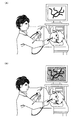
本実施形態の手法について、図1(A)、図1(B)及び図2を参照して説明する。 The method of this embodiment is demonstrated with reference to FIG. 1 (A), FIG. 1 (B), and FIG.
図1(A)及び図1(B)は従来の手法を示している。図1(A)は通常光による観察の様子を示したものである。全体に明るく、見やすい画像が得られるが、扁平上皮癌等の一部の病変については視認が困難である。また図1(B)は特殊光(狭帯域光)による観察の様子を示したものである。例えば扁平上皮癌等の病変が褐色で表示されるなど、一部の病変の視認性を通常光観察に比べて高めることが可能になるが、全体に暗く、見づらい画像になってしまう。 1A and 1B show a conventional method. FIG. 1A shows a state of observation with normal light. Although a bright and easy-to-view image is obtained as a whole, it is difficult to visually recognize some lesions such as squamous cell carcinoma. FIG. 1B shows an observation state using special light (narrow band light). For example, it is possible to improve the visibility of some lesions compared to normal light observation, for example, lesions such as squamous cell carcinoma are displayed in brown, but the whole image becomes dark and difficult to see.
このような問題を解決するために、通常光画像と特殊光画像を機器のスイッチ等を操作することで切り替えながら表示し、診断や治療を行う手法も考えられる。しかしこの手法では、内視鏡の挿入部を動かすと同時に機器の操作を行い、さらに画面を参照する必要があり、ドクターに負荷がかかってしまう。さらに表示される通常光画像も特殊光画像も欠点を有しているため、状況に応じて適切に表示画像を選択する必要があり、そのためには熟練を要する可能性が高い。 In order to solve such a problem, a method of performing diagnosis and treatment by displaying a normal light image and a special light image while switching them by operating a switch or the like of the device is also conceivable. However, in this method, it is necessary to operate the device at the same time as moving the insertion portion of the endoscope, and to refer to the screen, which places a burden on the doctor. Furthermore, since both the normal light image and the special light image to be displayed have drawbacks, it is necessary to select a display image appropriately according to the situation, and for that purpose, there is a high possibility that skill is required.
また、通常光画像と特殊光画像を並べて表示する手法も考えられるが、その場合は2つの画面を同時に参照しなくてはならず、病変部を見落とすおそれがあるなど、やはりドクターの負荷が大きい。 In addition, a method of displaying a normal light image and a special light image side-by-side is also conceivable, but in that case, the two screens must be referred to at the same time, and there is a risk that the lesion may be overlooked. .
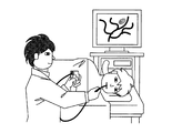
そこで本出願人は図2のようなシステムを提案する。本実施形態では、特殊光画像から粘膜表層の毛細血管、粘膜微細模様を抽出し、抽出された情報を元に通常光画像に合成処理することで、例えば扁平上皮癌等の病変部の視認性を高めている。 Therefore, the present applicant proposes a system as shown in FIG. In this embodiment, capillaries and mucous membrane fine patterns on the mucosal surface layer are extracted from the special light image, and the normal light image is synthesized based on the extracted information, so that the visibility of the lesioned part such as squamous cell carcinoma is visible. Is increasing.
これにより、通常光画像の利点である明るく見やすい画像の上に、特殊光画像の利点である病変部の視認性の高さが加わるため、病変部の見落としを抑止し、ドクターの負荷を軽減することで、スムーズな診断・治療を行うことが可能になる。 As a result, the high visibility of the lesion, which is an advantage of the special light image, is added to the bright, easy-to-view image that is an advantage of the normal light image, thereby suppressing the oversight of the lesion and reducing the doctor's load. Thus, smooth diagnosis and treatment can be performed.
なお、本実施形態においても、機器のスイッチ等を操作することで、特殊光画像を表示することが可能なのは言うまでもない。これにより、例えば、病変部のサーチには合成処理した通常光画像、病変部の詳細の確認には特殊光画像といったように、画像を適宜使い分けることも可能である。 In this embodiment, it goes without saying that a special light image can be displayed by operating a switch or the like of the device. As a result, for example, a normal light image that has been combined is used for searching for a lesion, and a special light image is used for confirming the details of a lesion.
2.第1の実施形態 2. First embodiment
まず本実施形態の手法について図3、図4を用いて説明する。 First, the method of this embodiment will be described with reference to FIGS.
図3はG成分の合成を説明するための図である。特殊光画像はG2,B2の2成分を持っている(ここでは特殊光画像としてNBI画像を想定している)ため、そのうちのG2成分を抽出する。また通常光画像はR,G,Bの3成分を持っているため、G2成分に対応する成分であるG成分を抽出する。 FIG. 3 is a diagram for explaining the synthesis of the G component. Since the special light image has two components G2 and B2 (here, an NBI image is assumed as the special light image), the G2 component is extracted. Since the normal light image has three components of R, G, and B, the G component that is a component corresponding to the G2 component is extracted.
そして通常光画像のG成分の明るさ情報であるwliAveGと、特殊光画像のG2成分の明るさ情報であるnbiAveGの比から後述する式(3)を用いてratioGを求める。求めたratioGを用いて、後述する式(4)により、特殊光画像のG2成分の明るさ補正を行い、補正後特殊光画像(G成分)を取得する。 Then, ratio G is obtained from the ratio of wliAveG, which is the brightness information of the G component of the normal light image, and nbiAveG, which is the brightness information of the G2 component of the special light image, using Equation (3) described later. Using the obtained ratioG, the brightness correction of the G2 component of the special light image is performed by Equation (4) described later to obtain a corrected special light image (G component).
取得した補正後特殊光画像と、通常光画像のG成分とを合成比blendGを用いて、後述する式(24)により合成することで、出力画像(G成分)を取得する。なお本実施形態の処理の目的は出力画像を取得することであり、以下に説明する処理は合成比blendGを求めるための処理である。 The obtained special light image after correction and the G component of the normal light image are combined according to the expression (24) described later using the combination ratio blendG, thereby acquiring the output image (G component). Note that the purpose of the processing of the present embodiment is to acquire an output image, and the processing described below is processing for obtaining the synthesis ratio blendG.
合成比blendGを求めるために、補正後特殊光画像に対してラプラシアンフィルタを適用し、lapImgGを取得する。そしてlapImgGにおいて、後述する式(8)〜(15)を用いてエッジ方向を判別し、エッジ方向の画素値の平均値を取るような方向依存フィルタを適用することでAveG画像を取得する。 In order to obtain the composite ratio blendG, a Laplacian filter is applied to the corrected special light image to obtain lapImgG. In lapImgG, the edge direction is determined using equations (8) to (15) described later, and an aveG image is obtained by applying a direction-dependent filter that takes an average value of pixel values in the edge direction.
さらに、AveG画像に対して後述する式(16)〜(20)のコアリング処理を行うことで、エッジ情報画像であるedgeGを取得する。そしてedgeGに係数K1をかけることで合成比画像blendGを取得し、取得したblendGを合成比として、前述したように通常光画像のG成分と補正後特殊光画像との合成処理を行い、出力画像を取得する。 Furthermore, edgeG, which is an edge information image, is acquired by performing coring processing of formulas (16) to (20) described later on the AveG image. Then, a composite ratio image blendG is acquired by multiplying edgeG by a coefficient K1, and the combined processing of the G component of the normal light image and the corrected special light image is performed as described above using the acquired blendG as the composite ratio, and the output image To get.
特殊光画像はB2成分も持っているため、同様に、通常光画像のB成分との合成処理を行う。処理の概要を示したものが図4である。 Since the special light image also has a B2 component, similarly, a synthesis process with the B component of the normal light image is performed. FIG. 4 shows an outline of the processing.
処理の内容はG成分の合成と同様である。通常光画像のB成分の明るさ情報と、特殊光画像のB2成分の明るさ情報からratioBを求めて、特殊光画像のB2成分の明るさ補正を行う。そして、通常光画像のB成分と、補正後特殊光画像(B成分)とを合成比blendBで合成することで出力画像(B成分)を取得する。 The content of the process is the same as the synthesis of the G component. RatioB is obtained from the brightness information of the B component of the normal light image and the brightness information of the B2 component of the special light image, and the brightness correction of the B2 component of the special light image is performed. Then, the output image (B component) is acquired by combining the B component of the normal light image and the corrected special light image (B component) at the combination ratio blendB.
合成比blendBは、補正後特殊光画像に対してラプラシアンフィルタと方向依存フィルタを適用した後、コアリング処理を行ってエッジ情報画像edgeBを求め、edgeBに対して係数K2をかけることで求められる。 The composite ratio blendB is obtained by applying a Laplacian filter and a direction-dependent filter to the corrected special light image, performing a coring process to obtain an edge information image edgeB, and multiplying edgeB by a coefficient K2.
なお、特殊光画像にはRチャネルに対応する成分が存在しないため、出力画像のR成分は通常光画像のR成分をそのまま用いる(後述する式(23))。 Since there is no component corresponding to the R channel in the special light image, the R component of the normal light image is used as it is as the R component of the output image (formula (23) described later).
このようにして得られた出力画像のR成分、B成分、G成分からカラー画像を生成する。生成された画像は、血管等が自然な色味で強調された画像となっているため、血管等の構造や病変部の視認性が向上しており、診断においてドクターの負荷を軽減すること等が可能になる。 A color image is generated from the R component, B component, and G component of the output image thus obtained. The generated image is an image in which blood vessels and the like are emphasized with natural colors, so the visibility of the structure of the blood vessels and lesions is improved, reducing the doctor's load in diagnosis, etc. Is possible.
以下、システム構成及び上述した処理に関して詳細に説明する。 Hereinafter, the system configuration and the above-described processing will be described in detail.
本実施形態に係る画像処理装置及びこれを含む内視鏡システムについて、図5を参照して説明する。本実施形態に係る内視鏡システムは、光源部100と、挿入部200と、本実施形態の画像処理装置に対応する画像処理部300と、表示部400と、外部I/F部500を備えている。
An image processing apparatus according to the present embodiment and an endoscope system including the image processing apparatus will be described with reference to FIG. The endoscope system according to the present embodiment includes a
光源部100は、白色光を発生する白色光源110と白色光をライトガイドファイバ210に集光するための集光レンズ120を備えている。
The
挿入部200は、例えば体腔への挿入を可能にするため細長くかつ湾曲可能に形成されている。挿入部200は、光源部100で集光された光を導くためのライトガイドファイバ210と、ライトガイドファイバ210により先端まで導かれてきた光を拡散させて観察対象に照射する照明レンズ220と、観察対象から戻る反射光を集光する対物レンズ230と、集光した反射光を2つに分離するハーフミラー240と、分離された反射光を検出するための第1撮像素子250と第2撮像素子260を備えている。
The
第1撮像素子250は通常光画像を撮影するためのベイヤ配列の色フィルタを持つ撮像素子である。第1撮像素子250の色フィルタR,G,Bは例えば図6に示すような分光特性を持っている。第2撮像素子260は特殊光画像を撮影するための撮像素子であり、例えば図8に示すように2種類の狭帯域光G2とB2をそれぞれ透過する2種類の色フィルタg2とb2を市松状に並べたような色フィルタを持つ撮像素子である。第2撮像素子260の色フィルタg2、b2は例えば図7に示すように、b2が390〜445nm、g2が530〜550nmの波長帯域の光を透過させる透過率特性を有している。
The
画像処理部300(画像処理装置)はAD変換部310a、310bと通常光画像取得部320と特殊光画像取得部330と出力画像生成部340と選択部350と制御部360を備えている。制御部360は通常光画像取得部320、特殊光画像取得部330、出力画像生成部340、選択部350と双方向に接続されていて、これらを制御するようになっている。
The image processing unit 300 (image processing device) includes
外部I/F部500は、この画像処理装置(内視鏡システム)に対するユーザーからの入力等を行うためのインターフェースであり、電源のオン/オフを行うための電源スイッチ、撮影操作を開始するためのシャッタボタン、撮影モードやその他各種のモードを切り換えるためのモード切換ボタンなどを含んで構成されている。そして、この外部I/F部500は、入力された情報を、制御部360へ出力するようになっている。
The external I /
AD変換部310aは、第1撮像素子250から出力されるアナログ信号をデジタル信号に変換して出力する。AD変換部310bは第2撮像素子260から出力されるアナログ信号をデジタル信号に変換して出力する。
The
通常光画像取得部320は、例えばAD変換部310aから出力されるデジタル信号から通常光画像を取得する。特殊光画像取得部330は、例えばAD変換部310bから出力されるデジタル信号から特殊光画像を取得する。通常光画像取得部320及び特殊光画像取得部330の詳細については後述する。
The normal light
通常光画像取得部320で取得された通常光画像と、特殊光画像取得部330で取得された特殊光画像は出力画像生成部340に出力される。特殊光画像取得部330で取得された特殊光カラー画像は選択部350に出力される。出力画像生成部340はこれら2枚の画像から1枚の合成画像を生成して選択部350に出力する。選択部350は、表示画像を表示部400に出力する。出力画像生成部340の詳細については後述する。
The normal light image acquired by the normal light
次に通常光画像取得部320について図9を用いて説明する。通常光画像取得部320は通常光画像生成部321と通常光画像記憶部322を備えている。AD変換部310aは、通常光画像生成部321に接続されている。通常光画像生成部321は、通常光画像記憶部322に接続されている。通常光画像記憶部322は、出力画像生成部340に接続されている。
Next, the normal light
通常光画像生成部321はAD変換部310aで変換されて入力されるデジタル信号に対して画像処理を行い、通常光画像を生成する。具体的には、既存の補間処理やホワイトバランス、色変換、階調変換等の処理を行い、通常光画像を生成する。通常光画像における座標(x,y)の、R、G、B信号値をそれぞれr(x,y)、g(x,y)、b(x,y)と表記する。通常光画像記憶部322は通常光画像生成部321から出力された通常光画像を記憶する。通常光画像記憶部322に記憶された通常光画像は出力画像生成部340へ出力される。
The normal light
次に特殊光画像取得部330について図10を用いて説明する。特殊光画像取得部330は特殊光画像生成部331と特殊光画像記憶部332を備えている。AD変換部310bは、特殊光画像生成部331に接続されている。特殊光画像生成部331は、特殊光画像記憶部332と、選択部350に接続されている。特殊光画像記憶部332は、出力画像生成部340に接続されている。
Next, the special light
特殊光画像生成部331はAD変換部310bで変換されて入力されるデジタル画像信号に対して画像処理を行い、特殊光画像を生成する。
The special light
ここで、特殊光画像生成部331で特殊光画像を生成する方法について説明する。特殊光画像生成部に入力されるデジタル画像信号は、前述したように図8で示す2種類の色フィルタg2とb2を市松状に並べたような画像信号である。このような画像信号に対してまず補間処理を行い、全画素でg2フィルタの信号値を持つG2画像と、全画素でb2フィルタの信号値を持つB2画像を生成する。ここで、特殊光画像における座標(x,y)の、GB信号値をそれぞれg2(x,y)、b2(x,y)と表記する。補間処理で算出される画素値は例えば周辺4画素の平均値とすればよく、例えば図8のg2(1,1)の位置でのb2の画素値b2(1,1)、及びb2(1,2)位置でのg2の画素値g2(1,2)は、下式(1)、(2)のように算出される。
Here, a method for generating a special light image by the special light
b2(1,1)=[b2(0,1)+b2(1,0)+b2(1,2)+b2(2,1)]/4 ・・・・・(1) b2 (1,1) = [b2 (0,1) + b2 (1,0) + b2 (1,2) + b2 (2,1)] / 4 (1)
g2(1,2)=[g2(0,2)+g2(1,1)+g2(1,3)+g2(2,2)]/4 ・・・・・(2) g2 (1,2) = [g2 (0,2) + g2 (1,1) + g2 (1,3) + g2 (2,2)] / 4 (2)
ここで、特殊光画像記憶部332は特殊光画像生成部331から出力された特殊光画像を記憶する。特殊光画像記憶部332に記憶された特殊光画像は出力画像生成部340へ出力される。
Here, the special light
次に、出力画像生成部340の具体的な構成について説明する。図11は、第1の実施形態における出力画像生成部340の構成の一例を説明するブロック図である。出力画像生成部340は、補正部341と、合成部342とを備えている。
Next, a specific configuration of the output
ここで、通常光画像取得部320からの画像信号は、補正部341と、合成部342に出力される。また、特殊光画像取得部330からの画像信号は、補正部341に出力される。補正部341は、合成部342に接続されている。合成部342は、選択部350に接続されている。合成部342の詳細については後述する。また、制御部360は、補正部341と、合成部342に双方向に接続されていて、これらを制御するようになっている。
Here, the image signal from the normal light
補正部341は、制御部360の制御に基づき、特殊光画像内の画素の特徴量と、通常光画像内の画素の特徴量の比に基づいて、特殊光画像の補正処理を行う。ここで、補正処理とは、特殊光画像を通常光画像と同程度の明るさに補正する。ここでは、特徴量として各画像内のG信号を用いる。具体的には、特殊光画像内のG信号の平均値をnbiAveG、通常光画像内のG信号の平均値をwliAveGと表記する。特殊光画像のG信号に対する、通常光画像のG信号の比ratioGは、下式のように算出される。
Based on the control of the
ratioG = K0 × wliAveG / nbiAveG ・・・・・(3) ratioG = K0 x wliAveG / nbiAveG (3)
K0は定数項である。設定された信号比ratioGを、特殊光画像の全画素のG信号およびB信号に対して乗算する。ここで、信号比を乗算された特殊光画像は、補正後特殊光画像として、座標(x,y)におけるB、G信号をそれぞれg2’(x,y)、b2’(x,y)と表記する。 K0 is a constant term. The set signal ratio ratioG is multiplied by the G signal and B signal of all the pixels of the special light image. Here, the special light image multiplied by the signal ratio is a corrected special light image, and the B and G signals at the coordinates (x, y) are g2 ′ (x, y) and b2 ′ (x, y), respectively. write.
g2’(x,y) = ratioG ×g2(x,y) ・・・・・(4) g2 ’(x, y) = ratioG × g2 (x, y) (4)
b2’(x,y) = ratioG ×b2(x,y) ・・・・・(5) b2 ’(x, y) = ratioG × b2 (x, y) (5)
また、信号比の算出方法は上記に限らず、特殊光画像内のB信号の平均値と、通常光画像内のB信号の平均値を用い、信号比ratioBを算出し、特殊光画像のB信号に対してはratioBを乗算してもよい。 The signal ratio calculation method is not limited to the above, and the signal ratio ratioB is calculated using the average value of the B signal in the special light image and the average value of the B signal in the normal light image, and the B of the special light image is calculated. The signal may be multiplied by ratioB.
ratioB = K0 × wliAveB / nbiAveB ・・・・・(6) ratioB = K0 x wliAveB / nbiAveB (6)
b2’(x,y) = ratioB ×b2(x,y) ・・・・・(7) b2 ’(x, y) = ratioB × b2 (x, y) (7)
また、各信号の平均値は、例えばN×M画素の複数の領域に分割し、領域毎に平均値を算出し、領域毎の信号比を算出してもよい。また、領域分割の手法はテクスチャ解析に代表される公知の領域分割アルゴリズムを適用してもよい。補正後特殊光画像は、合成部342へ出力される。
Further, the average value of each signal may be divided into a plurality of areas of N × M pixels, for example, the average value may be calculated for each area, and the signal ratio for each area may be calculated. In addition, a known area division algorithm represented by texture analysis may be applied as the area division method. The corrected special light image is output to the combining
合成部342は、制御部360の制御に基づいて通常光画像に、補正された特殊光画像を合成する。合成部342の具体的な構成について説明する。図12は、第1の実施形態における合成部342の構成の一例を説明するブロック図である。図12に示すように、合成部342は、エッジ抽出部3421と、合成比算出部3422と、合成画像作成部3423とを含んでいる。
The
ここで、通常光画像取得部320は、エッジ抽出部3421と、合成画像作成部3423に接続されている。また、補正部341は、エッジ抽出部3421に接続されている。エッジ抽出部3421は、合成比算出部3422に接続されている。合成比算出部3422は、合成画像作成部3423に接続されている。合成画像作成部3423は、選択部350に接続されている。また、制御部360は、エッジ抽出部3421と、合成比算出部3422と、合成画像作成部3423とに双方向に接続されていて、これらを制御するようになっている。
Here, the normal light
エッジ抽出部3421は、制御部360の制御に基づき、補正された特殊光画像内のエッジ情報と、通常光画像内のエッジ情報を抽出する。ここでは、特殊光画像のG信号値と、特殊光画像のB信号値に対して、方向判別エッジ抽出を行う。
The
ここでは、特殊光画像のG信号に対して処理を行った例を示すが、特殊光画像のB信号に対しても同様の処理を行う。具体的にはまず、特殊光画像のG信号に対してラプラシアンフィルタを適用しエッジ画像lapImgGを作成する。 Here, an example is shown in which processing is performed on the G signal of the special light image, but similar processing is performed on the B signal of the special light image. Specifically, first, an Laplacian filter is applied to the G signal of the special light image to create an edge image lapImgG.
次に、エッジ画像lapImgGの全画素に対して、エッジ成分がどの方向のエッジに含まれるかを8方向から判定する。図14(A)〜図14(D)はエッジ方向判別に使用する画素と方向である。具体的には注目画素の周辺5×5画素を使って評価値を算出し、最小値を示す方向を判別結果とする。下式(8)〜(15)に注目画素が座標(2,2)の場合の評価式を示す。 Next, it is determined from the eight directions in which direction the edge component is included in all pixels of the edge image lapImgG. 14A to 14D show pixels and directions used for edge direction discrimination. Specifically, the evaluation value is calculated using 5 × 5 pixels around the target pixel, and the direction indicating the minimum value is set as the determination result. The following formulas (8) to (15) show the evaluation formulas when the target pixel is the coordinates (2, 2).
e0G(2,2) = |g2’(2,2)-g2’(2,3)|+|g2’(2,2)-g2’(2,4)|
+|g2’(2,2)-g2’(2,1)|+|g2’(2,2)-g2’(2,0)| ・・・・(8)
e0G (2,2) = | g2 '(2,2) -g2' (2,3) | + | g2 '(2,2) -g2' (2,4) |
+ | g2 '(2,2) -g2' (2,1) | + | g2 '(2,2) -g2' (2,0) | (8)
e1G(2,2) = |g2’(2,2)-g2’(2,3)|+|g2’(2,2)-g2’(1,4)|
+|g2’(2,2)-g2’(2,1)|+|g2’(2,2)-g2’(3,0)| ・・・・(9)
e1G (2,2) = | g2 '(2,2) -g2' (2,3) | + | g2 '(2,2) -g2' (1,4) |
+ | g2 '(2,2) -g2' (2,1) | + | g2 '(2,2) -g2' (3,0) |
e2G(2,2) = |g2’(2,2)-g2’(1,3)|+|g2’(2,2)-g2’(0,4)|
+|g2’(2,2)-g2’(3,1)|+|g2’(2,2)-g2’(4,0)| ・・・・(10)
e2G (2,2) = | g2 '(2,2) -g2' (1,3) | + | g2 '(2,2) -g2' (0,4) |
+ | g2 '(2,2) -g2' (3,1) | + | g2 '(2,2) -g2' (4,0) |
e3G(2,2) = |g2’(2,2)-g2’(1,2)|+|g2’(2,2)-g2’(0,3)|
+|g2’(2,2)-g2’(3,2)|+|g2’(2,2)-g2’(4,1)| ・・・・(11)
e3G (2,2) = | g2 '(2,2) -g2' (1,2) | + | g2 '(2,2) -g2' (0,3) |
+ | g2 '(2,2) -g2' (3,2) | + | g2 '(2,2) -g2' (4,1) | (11)
e4G(2,2) = |g2’(2,2)-g2’(1,2)|+|g2’(2,2)-g2’(0,2)|
+|g2’(2,2)-g2’(3,2)|+|g2’(2,2)-g2’(4,2)| ・・・・(12)
e4G (2,2) = | g2 '(2,2) -g2' (1,2) | + | g2 '(2,2) -g2' (0,2) |
+ | g2 '(2,2) -g2' (3,2) | + | g2 '(2,2) -g2' (4,2) | (12)
e5G(2,2) = |g2’(2,2)-g2’(1,2)|+|g2’(2,2)-g2’(0,1)|
+|g2’(2,2)-g2’(3,2)|+|g2’(2,2)-g2’(4,3)| ・・・・(13)
e5G (2,2) = | g2 '(2,2) -g2' (1,2) | + | g2 '(2,2) -g2' (0,1) |
+ | g2 '(2,2) -g2' (3,2) | + | g2 '(2,2) -g2' (4,3) | (13)
e6G(2,2) = |g2’(2,2)-g2’(1,1)|+|g2’(2,2)-g2’(0,0)|
+|g2’(2,2)-g2’(3,3)|+|g2’(2,2)-g2’(4,4)| ・・・・(14)
e6G (2,2) = | g2 '(2,2) -g2' (1,1) | + | g2 '(2,2) -g2' (0,0) |
+ | g2 '(2,2) -g2' (3,3) | + | g2 '(2,2) -g2' (4,4) | (14)
e7G(2,2) = |g2’(2,2)-g2’(2,1)|+|g2’(2,2)-g2’(1,0)|
+|g2’(2,2)-g2’(2,3)|+|g2’(2,2)-g2’(3,4)| ・・・・(15)
e7G (2,2) = | g2 '(2,2) -g2' (2,1) | + | g2 '(2,2) -g2' (1,0) |
+ | g2 '(2,2) -g2' (2,3) | + | g2 '(2,2) -g2' (3,4) |
続いて、判別した結果を用いて、ラプラシアンフィルタで作成したエッジ画像lapImgGにエッジ方向に沿ったフィルタを適用する。これによりエッジを保持したままエッジ画像のノイズを低減する。具体的には、エッジ画像に対して、式(8)〜(15)で評価値が最小となった方向の評価値の算出に使用した5個の画素の平均値AveG(x,y)を算出し、方向依存フィルタの出力値とする。 Subsequently, using the determined result, a filter along the edge direction is applied to the edge image lapImgG created by the Laplacian filter. This reduces noise in the edge image while retaining the edge. Specifically, the average value AveG (x, y) of the five pixels used for calculating the evaluation value in the direction in which the evaluation value is minimized in Expressions (8) to (15) is calculated for the edge image. Calculate and use as the output value of the direction-dependent filter.
続いて、方向依存フィルタで算出された平均値AveG(x,y)に対してコアリング処理を行うことで、エッジ画像のノイズや方向判別の誤りによるアーティファクトを除去する。ここではコアリング量が平坦部では大きめに、エッジ部では小さめになるように適応的にコアリング量を制御する。 Subsequently, by performing coring processing on the average value AveG (x, y) calculated by the direction-dependent filter, artifacts due to edge image noise and direction determination errors are removed. Here, the coring amount is adaptively controlled so that the coring amount is larger at the flat portion and smaller at the edge portion.
具体的には、上式(8)、(10)、(12)、(14)で算出したe0G(x,y)、e2G(x,y)、e4G(x,y)、e6G(x,y)を比較し、その最大値evaMaxG(x,y)をエッジ量指標として使用する。各画素のコアリング量evaCoreG(x,y)はこのエッジ量指標evaMaxG(x,y)と、予め外部から与えられたパラメータである、最大コアリング量coreMaxG、最小コアリング量coreMinG、傾きslopeG、エッジ量指標の閾値TheGから下式(16)〜(18)で算出する。 Specifically, e0G (x, y), e2G (x, y), e4G (x, y), e6G (x, y) calculated by the above formulas (8), (10), (12), and (14). y) are compared, and the maximum value evaMaxG (x, y) is used as an edge amount index. The coring amount evaCoreG (x, y) of each pixel is the edge amount index evaMaxG (x, y) and the parameters given in advance from the outside, that is, the maximum coring amount coreMaxG, the minimum coring amount coreMinG, the slope slopeG, The following formulas (16) to (18) are calculated from the threshold value TheG of the edge amount index.
evaMaxGがTheGより小さい場合 When evaMaxG is smaller than TheG
evaCoreG(x,y)=coreMaxG ・・・・・(16) evaCoreG (x, y) = coreMaxG (16)
evaMaxGがTheG以上の場合 When evaMaxG is greater than TheG
evaCoreG(x,y)=coreMaxG-((evaMaxG(x,y)-TheG)×slopeG) ・・・・・(17) evaCoreG (x, y) = coreMaxG-((evaMaxG (x, y) -TheG) × slopeG) (17)
evaCoreGがcoreMinGより小さい場合 When evaCoreG is smaller than coreMinG
evaCoreG(x,y) = coreMinG ・・・・・(18) evaCoreG (x, y) = coreMinG (18)
次に、算出されたコアリング量evaCoreG(x,y)を用いて、方向依存フィルタ処理の出力値AveG(x,y)に対して下式(19)、(20)を用いてコアリング処理を行い、エッジ情報edgeG(x,y)を算出する。 Next, using the calculated coring amount evaCoreG (x, y), the coring processing is performed using the following expressions (19) and (20) for the output value AveG (x, y) of the direction-dependent filter processing. And edge information edgeG (x, y) is calculated.
AveG(x,y)が0以上の場合 When AveG (x, y) is 0 or more
edgeG(x,y) = AveG(x,y) - evaCoreG(x,y) ・・・・・(19) edgeG (x, y) = AveG (x, y)-evaCoreG (x, y) (19)
ここで、edgeG(x,y)が0より小さくなったらedgeG(x,y)に0を代入する。 Here, when edgeG (x, y) becomes smaller than 0, 0 is substituted into edgeG (x, y).
AveG(x,y)が0より小さい場合 When AveG (x, y) is less than 0
edgeG(x,y) = AveG(x,y) + evaCoreG(x,y) ・・・・・(20) edgeG (x, y) = AveG (x, y) + evaCoreG (x, y) (20)
ここで、edgeG(x,y)が0より大きくなったらedgeG(x,y)に0を代入する If edgeG (x, y) is greater than 0, substitute 0 for edgeG (x, y)
ここでは、エッジ情報として方向判別フィルタを用いたが、これに限らず公知のエッジ抽出手法を用いてもよい。作成された、特殊光画像のG信号値のエッジ画像edgeGと、特殊光画像のB信号値のエッジ画像edgeBは、合成比算出部3422に出力される。
Here, the direction discrimination filter is used as the edge information, but not limited to this, a known edge extraction method may be used. The created edge image edgeG of the G signal value of the special light image and edge image edgeB of the B signal value of the special light image are output to the synthesis
合成比算出部3422は、制御部360の制御に基づき、エッジ抽出部3421で抽出されたエッジ情報に基づき合成比を算出する。具外的には、下式(21)、(22)を用いて合成比blendG、blendBを算出する。
The composition
blendG(x,y) = K1×edgeG(x,y) ・・・・・(21) blendG (x, y) = K1 × edgeG (x, y) (21)
blendB(x,y) = K2×edgeB(x,y) ・・・・・(22) blendB (x, y) = K2 × edgeB (x, y) (22)
K1、K2は定数項である。ここで、合成比blendG(x,y)、blendB(x,y)が、1以上の場合は1、0以下の場合は0を代入する。また、合成比の算出方法は上記に限らず、補正された特殊光画像を領域分割し、領域毎にエッジ情報の平均値edgeAveG、edgeAveBを求め、エッジ情報の平均値を用いて合成比を算出しても良い。算出した合成比blendG、blendBは、合成画像作成部3423に出力される。
K1 and K2 are constant terms. Here, if the synthesis ratio blendG (x, y) and blendB (x, y) are 1 or more, 1 is substituted, and if it is 0 or less, 0 is substituted. The method for calculating the synthesis ratio is not limited to the above, and the corrected special light image is divided into regions, average values edgeAgeG and edgeAveB of edge information are obtained for each region, and the synthesis ratio is calculated using the average value of edge information. You may do it. The calculated composition ratios blendG and blendB are output to the composite
合成画像作成部3423は、制御部360の制御に基づき、合成比算出部3422で算出された合成比に基づき、特殊光画像と、通常光画像を合成する。具体的には、合成画像のRGB信号をそれぞれR(x,y)、G(x,y)、B(x,y)と表記して、下式で算出する。
Based on the control of the
R(x,y)=r(x,y) ・・・・・(23) R (x, y) = r (x, y) (23)
G(x,y)=(1-blendG(x,y))×g(x,y)+blendG(x,y)×g2’(x,y) ・・・・・(24) G (x, y) = (1-blendG (x, y)) × g (x, y) + blendG (x, y) × g2 ′ (x, y) (24)
B(x,y)=(1-blendB(x,y))×b(x,y)+blendB(x,y)×b2’(x,y) ・・・・・(25) B (x, y) = (1-blendB (x, y)) × b (x, y) + blendB (x, y) × b2 ′ (x, y) (25)
合成画像は、選択部350に出力される。
The composite image is output to the
選択部350は、制御部360の制御に基づき、表示画像の選択を行う。ここでは、外部I/F部500により選択された撮影モードに応じて、特殊光カラー画像と合成画像のどちらかを表示画像として設定する。設定された表示画像は表示部400へ出力される。
The
なお、合成部342の構成は前述のものに限定されない。例えば図13に示すように、合成部342は、注目領域検出部3425と、合成比算出部3422と、合成画像作成部3423とを含んでもよい。
Note that the configuration of the combining
注目領域検出部3425は、注目すべき領域を検出する。注目すべき領域とは血管等のエッジ情報に限定されず、例えば、病変部等であってもよい。そして合成比算出部3422は、注目領域が検出されたところでは補正後特殊光画像の合成比率を高く設定し、注目領域が検出されなかったところでは補正後特殊光画像の合成比率を低く設定する。
The attention
例えばNBI観察においては、G2成分、B2成分をR,G,Bのうちの所定のチャネルに入力し、擬似カラー画像を生成することで、扁平上皮癌等の特定の病変が褐色で表示されることになる。そのため、褐色の領域(例えば色相Hが5〜35の範囲にある領域)を病変部であると認識し、注目領域として検出することができる。 For example, in NBI observation, a specific lesion such as squamous cell carcinoma is displayed in brown by inputting a G2 component and a B2 component to a predetermined channel of R, G, and B and generating a pseudo color image. It will be. Therefore, a brown region (for example, a region where the hue H is in the range of 5 to 35) can be recognized as a lesion and detected as a region of interest.
ただし、合成の方法に関しては、前述した式(23)〜(25)を用いる。つまり、通常光画像のG成分と特殊光画像のG2成分、通常光画像のB成分と特殊光画像のB2成分を合成するのであって、通常光画像と擬似カラー化した(R,G,Bの3成分を持っている)特殊光画像を合成するのではない点には注意が必要である。 However, with respect to the synthesis method, the above-described formulas (23) to (25) are used. That is, the G component of the normal light image and the G2 component of the special light image, and the B component of the normal light image and the B2 component of the special light image are synthesized, and are pseudo-colored with the normal light image (R, G, B). Note that it does not synthesize special light images.
また、注目領域であることの確からしさを示す信頼度という尺度を導入し、信頼度が高いほど補正後特殊光画像の合成比率を高く設定してもよい。信頼度としては、例えば褐色領域(病変部)の面積などを用いることができる。 Further, a scale called reliability indicating the certainty of being an attention area may be introduced, and the higher the reliability, the higher the composite ratio of the corrected special light image may be set. As the reliability, for example, the area of a brown region (lesion) can be used.
また、本実施の形態では、画像処理部300を構成する各部をハードウェアで構成することとしたが、これに限定されるものではない。例えば、カプセル内視鏡などの撮像装置を用いて予め取得された画像に対して、CPUが各部の処理を行う構成とし、CPUがプログラムを実行することによってソフトウェアとして実現することとしてもよい。あるいは、各部が行う処理の一部をソフトウェアで構成することとしてもよい。
In the present embodiment, each part of the
撮像部とAD変換部を別体とし、AD変換部を除く画像処理部300の各部が行う処理をソフトウェアとして実現する場合には、ワークステーションやパソコン等の公知のコンピューターシステムを画像処理装置として用いることができる。そして、画像処理部300の各部が行う処理を実現するためのプログラム(画像処理プログラム)を予め用意し、この画像処理プログラムをコンピューターシステムのCPUが実行することによって実現できる。
When the imaging unit and the AD conversion unit are separated and the processing performed by each unit of the
図15は、本変形例におけるコンピューターシステム600の構成を示すシステム構成図であり、図16は、このコンピューターシステム600における本体部610の構成を示すブロック図である。図15に示すように、コンピューターシステム600は、本体部610と、本体部610からの指示によって表示画面621に画像等の情報を表示するためのディスプレイ620と、このコンピューターシステム600に種々の情報を入力するためのキーボード630と、ディスプレイ620の表示画面621上の任意の位置を指定するためのマウス640とを備える。
FIG. 15 is a system configuration diagram showing the configuration of the
また、このコンピューターシステム600における本体部610は、図16に示すように、CPU611と、RAM612と、ROM613と、ハードディスクドライブ(HDD)614と、CD−ROM660を受け入れるCD−ROMドライブ615と、USBメモリ670を着脱可能に接続するUSBポート616と、ディスプレイ620、キーボード630およびマウス640を接続するI/Oインターフェース617と、ローカルエリアネットワークまたは広域エリアネットワーク(LAN/WAN)N1に接続するためのLANインターフェース618を備える。
Further, as shown in FIG. 16, the
さらに、このコンピューターシステム600には、インターネット等の公衆回線N3に接続するためのモデム650が接続されるとともに、LANインターフェース618およびローカルエリアネットワークまたは広域エリアネットワークN1を介して、他のコンピューターシステムであるパソコン(PC)681、サーバ682、プリンタ683等が接続される。
Further, the
そして、このコンピューターシステム600は、所定の記録媒体に記録された画像処理プログラム(例えば図17〜図18を参照して後述する処理手順を実現するための画像処理プログラム)を読み出して実行することで画像処理装置を実現する。ここで、所定の記録媒体とは、CD−ROM660やUSBメモリ670の他、MOディスクやDVDディスク、フレキシブルディスク(FD)、光磁気ディスク、ICカード等を含む「可搬用の物理媒体」、コンピューターシステム600の内外に備えられるHDD614やRAM612、ROM613等の「固定用の物理媒体」、モデム650を介して接続される公衆回線N3や、他のコンピューターシステム(PC)681またはサーバ682が接続されるローカルエリアネットワークまたは広域エリアネットワークN1等のように、プログラムの送信に際して短期にプログラムを記憶する「通信媒体」等、コンピューターシステム600によって読み取り可能な画像処理プログラムを記録するあらゆる記録媒体を含む。
The
すなわち、画像処理プログラムは、「可搬用の物理媒体」「固定用の物理媒体」「通信媒体」等の記録媒体にコンピュータ読み取り可能に記録されるものであり、コンピューターシステム600は、このような記録媒体から画像処理プログラムを読み出して実行することで画像処理装置を実現する。なお、画像処理プログラムは、コンピューターシステム600によって実行されることに限定されるものではなく、他のコンピューターシステム(PC)681またはサーバ682が画像処理プログラムを実行する場合や、これらが協働して画像処理プログラムを実行するような場合にも、本発明を同様に適用することができる。
That is, the image processing program is recorded on a recording medium such as “portable physical medium”, “fixed physical medium”, and “communication medium” so that the computer system can read the
各部が行う処理の一部をソフトウェアで構成する場合の一例として、予め取得された通常光画像と特殊光画像に対して、図11の出力画像生成部340の処理をソフトウェアで実現する場合の処理手順を、図17のフローチャートを用いて説明する。
As an example of a case where a part of processing performed by each unit is configured by software, processing when the processing of the output
この処理を開始すると、まず、時系列の通常光画像と、特殊光画像に対して、撮影モードなどのヘッダ情報を入力する(S11)。次に、特殊光画像と通常光画像を予め確保しておいた画像バッファに入力する(S12)。続いて、入力された通常光画像に対し既存の補間処理やホワイトバランス、色変換、階調変換等の処理を行い通常光画像を作成する(S13)。 When this processing is started, first, header information such as a shooting mode is input to the time-series normal light image and special light image (S11). Next, the special light image and the normal light image are input to an image buffer secured in advance (S12). Subsequently, the input normal light image is subjected to existing interpolation processing, white balance, color conversion, gradation conversion, and the like to create a normal light image (S13).
さらに、入力された特殊光画像に対し式(1)〜(2)で上述した通り、特殊光画像を作成する(S14)。そして、式(3)〜(5)で上述した通り、特殊光画像内の画素の特徴量と、通常光画像内の画素の特徴量の比に基づいて、特殊光画像の補正処理を行う(S15)。その後、後で図18を参照して詳細に説明するように、通常光画像に補正された特殊光画像を合成する(S16)。次に、合成処理された画像信号を出力する(S17)。そして、時系列で最終画像の処理が終了したか否かを判定して(S18)、終了していないと判定した場合にはS12へ戻って次の画像信号について上述したような処理を繰り返して行う。一方、全画像信号の処理が終了していると判定した場合には、この処理を終了する。 Further, a special light image is created for the input special light image as described above in equations (1) and (2) (S14). Then, as described above in the equations (3) to (5), the special light image is corrected based on the ratio between the feature amount of the pixel in the special light image and the feature amount of the pixel in the normal light image ( S15). Thereafter, as described in detail later with reference to FIG. 18, the corrected special light image is synthesized with the normal light image (S16). Next, the combined image signal is output (S17). Then, it is determined whether or not the processing of the final image has been completed in time series (S18). If it is determined that the processing has not ended, the process returns to S12 and the above-described processing is repeated for the next image signal. Do. On the other hand, when it is determined that the processing of all the image signals is finished, this processing is finished.
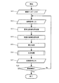
次に、図18を参照して、図17のS16における合成処理の詳細について説明する。
この処理を開始すると、まず、式(8)〜(20)で上述した通り、補正された特殊光画像内のエッジ情報を抽出する(S21)。続いて、式(21)〜(22)で上述した通り、抽出されたエッジ情報に基づき合成比を算出する(S22)。次に、式(23)〜(25)で上述した通り、通常光画像のB、G信号に補正された特殊光画像のB、G信号を合成した合成画像を作成する(S23)。
Next, with reference to FIG. 18, the details of the synthesizing process in S16 of FIG. 17 will be described.
When this process is started, first, edge information in the corrected special light image is extracted (S21) as described above in equations (8) to (20). Subsequently, as described above with Expressions (21) to (22), the composition ratio is calculated based on the extracted edge information (S22). Next, a composite image is created by synthesizing the B and G signals of the special light image corrected to the B and G signals of the normal light image as described above with Expressions (23) to (25) (S23).
このような処理を行うことで、通常光画像と特殊光画像を単一の画像で表示することが可能となるため、ドクターの負荷を低減しながら病変部の見逃しを抑止する画像処理装置(内視鏡システム)等を提供することが可能となる。 By performing such processing, it is possible to display the normal light image and the special light image as a single image. Therefore, an image processing apparatus (internal) that suppresses oversight of the lesion while reducing the load on the doctor. (Scope system) etc. can be provided.
以上の本実施形態では、図5に示す通常光画像取得部320は白色光の波長帯域における情報を有した被写体像を含む画像を取得し、特殊光画像取得部330は特定の波長帯域における情報を有した被写体像を含む画像を取得する。そして図11に示す補正部341は特殊光画像の補正処理を行い、合成部342は通常光画像に対して補正された特殊光画像の合成処理を行う。合成処理とは、通常光画像のG成分と補正後特殊光画像のG成分同士を合成する第1の合成処理(図3におけるC1)と、通常光画像のB成分と補正後特殊光画像のB成分同士を合成する第2の合成処理(図4におけるD1)の少なくとも一方のことである。
In the above embodiment, the normal light
ここで、成分とは、AD変換部によりアナログからデジタルに変換された際の出力である、RGBチャネルのデータのことである。 Here, the component is RGB channel data which is an output when converted from analog to digital by the AD conversion unit.
これにより、補正部341により補正された補正後特殊光画像を合成することで、通常光画像に比べて、粘膜表層の毛細血管や粘膜微細模様の視認性が高い画像を得ることができる。また、図3のC1、図4のD1に示したようにG成分同士、B成分同士を合成しているため、自然な色味で血管等の視認性を向上させることができる。よって、例えば内視鏡で生体内を通常光及び特殊光を用いて観察する場合には、通常光では視認が難しい病変部を特殊光観察で的確に捉えたうえで、本実施形態の方法を用いない場合に比べて視認性の高い態様で当該病変部を含む画像を表示することが可能になり、ドクターの負荷を軽減し、病変部の見落としを抑止することができる。
なお、本実施形態での説明において、G成分同士の合成及びB成分同士の合成の両方を行うものとしたが、これに限定されるものではない。G成分同士の合成は行い、B成分同士の合成は行わなくてもよい。また、B成分同士の合成は行い、G成分同士の合成は行わなくてもよい。
As a result, by combining the corrected special light image corrected by the
In the description of the present embodiment, both the G components and the B components are synthesized. However, the present invention is not limited to this. The G components may be combined, and the B components may not be combined. Further, the B components may be combined and the G components may not be combined.
また図12に示すように、合成部342は、エッジ抽出部3421と、合成比算出部3422とを含んでもよい。エッジ抽出部3421は補正された特殊光画像内のエッジ情報及び通常光画像のエッジ情報の少なくとも一方を抽出し、合成比算出部3422は抽出されたエッジ情報に基づき合成比を算出する。そして合成部342は、算出された合成比に基づき合成処理を行ってもよい。
As illustrated in FIG. 12, the
具体的には、エッジ情報とは図3におけるedgeGであり、合成比とは上述した式(21)のように、edgeGに係数K1をかけることで求められるblendGである。edgeGは図3で示したように、補正後特殊光画像に対してラプラシアンフィルタ、方向依存フィルタを適用後、コアリング処理をすることで求められる。 Specifically, the edge information is edgeG in FIG. 3, and the composition ratio is blendG obtained by multiplying edgeG by a coefficient K1 as in the above-described equation (21). As shown in FIG. 3, edgeG is obtained by applying a Laplacian filter and a direction- dependent filter to the corrected special light image and then performing coring processing.
ここで、エッジ情報は特殊光画像内の粘膜表層の毛細血管や粘膜微細模様を示す指標である。 Here, the edge information is an index indicating capillaries and mucous membrane fine patterns on the mucous membrane surface layer in the special light image.
これにより、特殊光画像内の粘膜表層の毛細血管や粘膜微細模様の含まれる画素について、病変部の視認性を向上させ、粘膜表層の毛細血管や粘膜微細模様の含まれない画素については従来通りの通常光画像を表示することで、従来の通常光に比べ病変部の視認性を向上させることが可能になり、ドクターの負荷を軽減し、病変部の見落としを抑止することができる。 This improves the visibility of lesions for pixels that contain capillaries and mucous fine patterns on the mucosal surface in the special light image, and pixels that do not contain capillaries and mucous micropatterns on the mucosal surface are the same as before. By displaying the normal light image, it becomes possible to improve the visibility of the lesioned part compared to the conventional normal light, reduce the load on the doctor, and suppress the oversight of the lesioned part.
また、合成比算出部3422は、補正後特殊光画像内にエッジが多い場合、補正後特殊光画像の合成比率を、エッジが少ない場合の補正後特殊光画像の合成比率と比べて高くしてもよい。具体的にはedgeGの値が大きいほど、補正後特殊光画像の合成比率が高くなる。これは上述した式(21)及び(24)からもわかる。式(24)に示したように補正後特殊光画像の合成比率はblendGであり、式(21)に示したように合成比blendGはedgeGにより決定されるためである。
Further, the composition
これにより、粘膜表層の毛細血管や粘膜微細模様が多い部分については、特殊光画像の比率を大きくすることで、病変部の視認性を向上させる。また、粘膜表層の毛細血管や粘膜微細模様が少ない部分については、明るくノイズの少ない通常光画像の比率が高くなることで視認性を向上させることが可能になり、ドクターの負荷を軽減し、病変部の見落としを抑止することができる。 As a result, for a portion of the mucosal surface layer where there are many capillaries and fine mucous patterns, the visibility of the lesion is improved by increasing the ratio of the special light image. In addition, in areas where there are few capillaries and fine mucous patterns on the surface of the mucosa, the ratio of normal light images that are bright and less noisy can be increased, improving visibility, reducing the burden on the doctor, Oversight of parts can be suppressed.
また、図12のエッジ抽出部3421は、補正後特殊光画像に対して、少なくとも方向依存フィルタを含むエッジ検出フィルタを適用することで、補正後特殊光画像内のエッジ情報を抽出する。具体的には例えば、補正後特殊光画像に対して、ラプラシアンフィルタ及び方向依存フィルタを適用することで、補正後特殊光画像のエッジ情報を抽出する。さらに具体的には図3におけるlapImgG及びAveGを求める処理に対応する。ここで方向依存フィルタとは、エッジ方向に沿った画素の画素値を平滑化するフィルタであってもよい。具体的には図14(A)〜図14(D)で示した8方向について、上述した式(8)〜(15)に基づいてエッジ方向を判別することになる。
The
これにより、方向依存フィルタを含むエッジ検出フィルタを適用することで、エッジ情報を抽出することができる。具体的には例えば、ラプラシアンフィルタを適用してエッジ画像を取得した上で、方向依存フィルタによりノイズ低減処理を行うことが可能になる。そのため、補正後特殊光画像のエッジ情報として、シャープなエッジを持った画像を取得することができる。 Thereby, edge information can be extracted by applying an edge detection filter including a direction-dependent filter. Specifically, for example, after an edge image is acquired by applying a Laplacian filter, it is possible to perform noise reduction processing using a direction-dependent filter. Therefore, an image having a sharp edge can be acquired as edge information of the corrected special light image.
また、エッジ抽出部3421は、通常光画像に対して、ラプラシアンフィルタ及び方向依存フィルタを適用することで、通常光画像のエッジ情報を抽出してもよい。具体的には後述する図19におけるlapImgY及びAveYを求める処理に対応する。
The
これにより、ラプラシアンフィルタを適用してエッジ画像を取得した上で、方向依存フィルタによりノイズ低減処理を行うことが可能になる。そのため、通常光画像のエッジ情報として、シャープなエッジを持った画像を取得することができる。 As a result, it is possible to perform noise reduction processing using the direction-dependent filter after obtaining an edge image by applying a Laplacian filter. Therefore, an image having a sharp edge can be acquired as edge information of the normal light image.
また、合成部342は、図13に示すように、注目領域検出部3425と、合成比算出部3422とを含んでもよい。注目領域検出部3425は、補正後特殊光画像内の注目すべき領域である注目領域を検出し、合成比算出部3422は検出された注目領域情報に基づき合成比を算出する。そして合成部342は、算出された合成比に基づき合成処理を行ってもよい。注目領域の検出は、具体的には例えば、特殊光画像のG2、B2信号から擬似カラー画像を生成し、色相Hの値を調べることで実現される。
Further, as illustrated in FIG. 13, the
これにより、特殊光画像内の注目領域(例えば病変部等)について、病変部の視認性を向上させ、注目領域以外の画素については従来通りの通常光画像を表示することで、従来の通常光に比べ病変部の視認性を向上させることが可能になる。 As a result, the visibility of the lesion area is improved for the attention area (for example, the lesion area) in the special light image, and the conventional ordinary light image is displayed for the pixels other than the attention area. Compared to the above, it becomes possible to improve the visibility of the lesion.
また、図13の合成比算出部3422は、注目領域が検出された場合は、検出されない場合に比べて、補正後特殊光画像の合成比率を高くしてもよい。
In addition, the composition
これにより、注目領域について特殊光画像の比率を大きくすることで、例えば病変部等の視認性を向上させることができる。また、注目領域以外の領域については、明るくノイズの少ない通常光画像の比率が高くなるため、視認性が向上する。 Thereby, by increasing the ratio of the special light image with respect to the attention area, for example, visibility of a lesioned part or the like can be improved. In addition, the visibility of the region other than the attention region is improved because the ratio of the normal light image that is bright and has little noise increases.
また、合成部342は、補正後特殊光画像を複数の領域に分割する分割部を含んでもよい。そして合成比算出部3422は、分割された各領域ごとに合成比を算出してもよい。
The combining
これにより、画素単位だけではなく、複数の画素を含む領域単位で処理を行うことが可能になる。そのため、計算量を削減することが可能になり、処理の高速化が実現できる。また、領域分割しない場合に比べ、画素毎に合成比が極端に変化することがなく、粘膜表層の毛細血管や粘膜微細模様が有る画素と無い画素が隣接している場合でもアーティファクトが発生しない。そのため病変部の視認性を向上させることが可能となり、ドクターの負荷を軽減し、病変部の見落としを抑止することができる。 Thus, it is possible to perform processing not only in pixel units but also in region units including a plurality of pixels. As a result, the amount of calculation can be reduced, and the processing speed can be increased. In addition, compared with the case where no region is divided, the composition ratio does not change extremely for each pixel, and no artifact occurs even when a pixel having a capillary or mucous fine pattern on the mucosal surface layer is adjacent to a pixel having no pattern. Therefore, the visibility of the lesioned part can be improved, the load on the doctor can be reduced, and oversight of the lesioned part can be suppressed.
また、特定の波長帯域とは、白色光の波長帯域よりも狭い帯域である。具体的には通常光画像及び特殊光画像は例えば生体内画像であり、特定の波長帯域とは、例えば血液中のヘモグロビンに吸収される波長の波長帯域である。さらに具体的には、図7に示すように390nm〜445nmまたは530nm〜550nmの波長帯域である。 The specific wavelength band is a band narrower than the wavelength band of white light. Specifically, the normal light image and the special light image are, for example, in-vivo images, and the specific wavelength band is, for example, a wavelength band of a wavelength that is absorbed by hemoglobin in blood. More specifically, as shown in FIG. 7, the wavelength band is 390 nm to 445 nm or 530 nm to 550 nm.
これにより、生体の表層部及び、深部に位置する血管の構造を観察することが可能になる。また得られた信号を特定のチャンネル(R,G,B)に入力することで、扁平上皮癌等の通常光では視認が難しい病変などを褐色等で表示することができ、病変部の見落としを抑止することができる。なお、390nm〜445nmまたは530nm〜550nmとはヘモグロビンに吸収されるという特性及び、それぞれ生体の表層部または深部まで到達するという特性から得られた数字である。 Thereby, it becomes possible to observe the structure of the blood vessel located in the surface layer part and the deep part of the living body. In addition, by inputting the obtained signals to specific channels (R, G, B), lesions that are difficult to see with normal light such as squamous cell carcinoma can be displayed in brown, etc. Can be deterred. Note that 390 nm to 445 nm or 530 nm to 550 nm is a number obtained from the characteristic of being absorbed by hemoglobin and the characteristic of reaching the surface layer or the deep part of the living body.
また、本実施形態は、図5及び図11に示すように通常光画像取得部320と、特殊光画像取得部330と、補正部341を含む画像処理装置であってもよい。通常光画像取得部320は白色光の波長帯域における情報を有した被写体像を含む画像を取得し、特殊光画像取得部330は特定の波長帯域における情報を有した被写体像を含む画像を取得する。補正部341は、特殊光画像の明るさ情報である特殊光明るさ情報に基づいて、特殊光画像の補正処理を行う。ここで、特殊光明るさ情報とは、図3におけるnbiAveGに対応する。
Further, the present embodiment may be an image processing apparatus including a normal light
これにより、特殊光明るさ情報を用いて特殊光画像の明るさ補正を行うことが可能になる。一般的に特殊光画像は非常に暗い画像となるため、明るさ補正を行うことで画像の視認性を高めることができる。 As a result, it is possible to correct the brightness of the special light image using the special light brightness information. Since the special light image is generally a very dark image, the visibility of the image can be improved by performing brightness correction.
また、図11の補正部341は、特殊光明るさ情報に加えて、通常光画像の明るさ情報である通常光明るさ情報を用いて、特殊光画像の補正処理を行ってもよい。ここで、通常光明るさ情報とは、図3におけるwliAveGに対応する。
In addition to the special light brightness information, the
これにより、通常光画像の明るさと特殊光画像の明るさとを比較した上で、明るさ補正を行うことが可能になる。 This makes it possible to perform brightness correction after comparing the brightness of the normal light image and the brightness of the special light image.
また、補正部341は、補正処理として、特殊光明るさ情報と通常光明るさ情報の明るさを同等にする処理を行ってもよい。
Further, the
これにより、非常に暗い特殊光画像の明るさを、通常光画像の明るさのレベルまで引き上げることが可能になり、視認性を向上させることができる。 As a result, the brightness of the very dark special light image can be raised to the brightness level of the normal light image, and the visibility can be improved.
また、補正部341は、特殊光明るさ情報と明るさ検知センサから得られた明るさ情報とに基づいて、特殊光画像の補正処理を行ってもよい。
The
ここで、明るさ検知センサ(調光センサ)とは、具体的には例えばフォトダイオード等により実現され、光起電力や光伝導等により動作することで、明るさを検知するものである。 Here, the brightness detection sensor (light control sensor) is specifically realized by, for example, a photodiode or the like, and detects brightness by operating by photovoltaic power or photoconduction.
これにより、明るさ情報をセンサ情報として取得することが可能になり、センサ情報に基づいて明るさ補正を行うことができる。 Thereby, it becomes possible to acquire brightness information as sensor information, and brightness correction can be performed based on sensor information.
また、補正部341は、特殊光画像内の画素値と、通常光画像内の画素値とに基づいて、特殊光画像の補正処理を行ってもよい。
Further, the
これにより、画素値に基づいた補正処理が可能になる。ここで画素値とは、例えばR,G,Bに1画素あたり各8ビットが割り当てられているような場合には、R,G,Bの各成分が取ることができる0〜255の値のことである。 Thereby, the correction process based on the pixel value can be performed. Here, the pixel value is, for example, a value of 0 to 255 that each component of R, G, and B can take when 8 bits are assigned per pixel to R, G, and B, for example. That is.
また、補正部341は、特殊光画像内の画素値に基づいて特殊光明るさ情報を算出するとともに、通常光画像内の画素値に基づいて通常光明るさ情報を算出してもよい。そして、通常光明るさ情報と特殊光明るさ情報に基づいて、特殊光画像の補正処理を行ってもよい。前述したとおり、特殊光明るさ情報は図3のnbiAveGに対応し、通常光明るさ情報は図3のwliAveGに対応する。
The
これにより、画素値に基づいて明るさ情報を算出することが可能になる。そして、通常光画像の明るさと特殊光画像の明るさとを比較した上で、明るさ補正を行うことができる。 This makes it possible to calculate brightness information based on the pixel value. Then, the brightness correction can be performed after comparing the brightness of the normal light image and the brightness of the special light image.
また、補正部341は、特殊光明るさ情報と通常光明るさ情報の比に応じた値を補正係数として算出し、補正係数を特殊光画像内の画素値に乗ずる処理を行う。具体的には例えば上述した式(3)、(4)のような処理が考えられる。
Further, the
これにより、具体的な補正係数として、特殊光明るさ情報と通常光明るさ情報の比、もしくは比に応じた値を用いて、補正処理を行うことが可能になる。 As a result, the correction process can be performed using the ratio of the special light brightness information and the normal light brightness information or a value corresponding to the ratio as a specific correction coefficient.
また、通常光画像は第1〜第Nの画素値の成分を含み(例えばR,G,Bの3成分)、特殊光画像は第1〜第Mの画素値の成分を含む(例えばG2,B2の2成分)。そして補正部341は、第1〜第Mの成分の少なくとも1つの成分に基づいて特殊光明るさ情報を算出する。さらに、特殊光明るさ情報の算出に用いた成分に対応する、通常光画像の対応成分に基づいて通常光明るさ情報を算出する。対応成分とは具体的には例えば、G成分、B成分の少なくとも一方が考えられる。具体的には図3に示すように、特殊光明るさ情報の算出にG2信号が用いられた場合には、対応成分はG成分となる。
The normal light image includes components of the first to Nth pixel values (for example, three components R, G, and B), and the special light image includes components of the first to Mth pixel values (for example, G2, G2, B). 2 components of B2). The
これにより、特殊光画像の画素値の成分の少なくとも1つから、特殊光明るさ情報を算出することが可能になる。また、対応する通常光画像の画素値の成分から、通常光明るさ情報を算出することが可能になる。対応成分とは、特殊光明るさ情報の算出にG2成分が用いられた場合は通常光画像のG成分であり、特殊光明るさ情報の算出にB2成分が用いられた場合は通常光画像のB成分である。 Thereby, the special light brightness information can be calculated from at least one of the component of the pixel value of the special light image. Further, it is possible to calculate the normal light brightness information from the pixel value component of the corresponding normal light image. The corresponding component is the G component of the normal light image when the G2 component is used for calculating the special light brightness information, and the corresponding component of the normal light image when the B2 component is used for calculating the special light brightness information. B component.
また、補正部341は、特殊光画像のG成分(G2成分)に基づいて特殊光明るさ情報を算出し、通常光画像のG成分に基づいて通常光明るさ情報を算出する。そして、特殊光明るさ情報と通常光明るさ情報に基づいて、補正処理を行う。具体的には、特殊光明るさ情報と通常光明るさ情報の比に応じた値を補正係数として算出し、算出した補正係数を特殊光画像のG成分とB成分に乗ずる処理を行ってもよい。さらに具体的には、例えば上述した式(3)〜(5)に対応する処理を行ってもよい。
Further, the
これにより、特殊光画像の明るさを、人の目の最も比視感度が高いG信号を用いて、通常光画像の明るさと同等程度にすることが可能となる。そのため病変部の視認性を向上させることが可能となり、ドクターの負荷を軽減し、病変部の見落としを抑止することができる。 As a result, the brightness of the special light image can be set to the same level as the brightness of the normal light image by using the G signal having the highest relative visibility of the human eye. Therefore, the visibility of the lesioned part can be improved, the load on the doctor can be reduced, and oversight of the lesioned part can be suppressed.
また、補正部341は、特殊光画像のG成分(G2成分)に基づいて第1の特殊光明るさ情報を算出し、通常光画像のG成分に基づいて第1の通常光明るさ情報を算出する。それとともに特殊光画像のB成分(B2成分)に基づいて第2の特殊光明るさ情報を算出し、通常光画像のB成分に基づいて第2の通常光明るさ情報を算出する。そして、第1の特殊光明るさ情報、第1の通常光明るさ情報、第2の特殊光明るさ情報及び第2の通常光明るさ情報に基づいて、補正処理を行ってもよい。
Further, the
具体的には、第1の特殊光明るさ情報と第1の通常光明るさ情報の比に応じた値を第1の補正係数として算出し、算出した第1の補正係数を特殊光画像のG成分に乗ずる処理を行う。また、第2の特殊光明るさ情報と第2の通常光明るさ情報の比に応じた値を第2の補正係数として算出し、算出した第2の補正係数を特殊光画像のB成分に乗ずる処理を行ってもよい。さらに具体的には、例えば上述した式(3)、(4)、(6)、(7)に対応する処理を行ってもよい。 Specifically, a value corresponding to the ratio between the first special light brightness information and the first normal light brightness information is calculated as the first correction coefficient, and the calculated first correction coefficient is used as the special light image. A process of multiplying the G component is performed. Further, a value corresponding to the ratio between the second special light brightness information and the second normal light brightness information is calculated as a second correction coefficient, and the calculated second correction coefficient is used as the B component of the special light image. A multiplication process may be performed. More specifically, for example, processing corresponding to the above-described formulas (3), (4), (6), and (7) may be performed.
これにより、G信号とB信号で独立に最適な明るさの補正を行うことができる。そのため従来の病変部の視認性を向上させることが可能となり、ドクターの負荷を軽減し、病変部の見落としを抑止することができる。 Thereby, optimal brightness correction can be performed independently for the G signal and the B signal. Therefore, it becomes possible to improve the visibility of the conventional lesioned part, reduce the doctor's load, and suppress the overlooked lesioned part.
また、通常光画像のG成分と補正後特殊光画像のG成分同士を合成するとともに、通常光画像のB成分と補正後特殊光画像のB成分同士を合成する処理を行う合成部342を含んでもよい。これは、図3におけるC1及び図4におけるD1に対応する。
Also included is a combining
これにより、明るさ補正が行われた特殊光画像と、通常光画像とを合成することが可能になる。本来非常に暗い特殊光画像に対して明るさ補正が行われているため、合成処理を行っても通常光画像が暗くなることがなく、病変部の視認性を高めることができる。
As a result, it is possible to synthesize the special light image subjected to the brightness correction and the normal light image. Since the original brightness correction for very dark special light image being performed, without the normal light image that darkens be performed combining process, it is possible to enhance the visibility of the lesion.
また、通常光画像取得部320は、白色光の波長帯域の光源からの光に基づいて通常光画像を取得してもよい。そして、特殊光画像取得部330は、特定の波長帯域の光源からの光に基づいて特殊光画像を取得してもよい。この場合の構成は図5の構成とは異なり、白色光源110の代わりに、白色光源及び特殊光光源の2つが、光源部100に設けられることになる。
The normal light
これにより、光源の構成により通常光画像と特殊光画像を取得することが可能になる。フィルタ等を適用する必要がなくなるため、挿入部200等の構成の一部を簡略化することができる。
Thereby, it becomes possible to acquire a normal light image and a special light image by the configuration of the light source. Since it is not necessary to apply a filter or the like, a part of the configuration of the
また、通常光画像取得部320は、光源からの光に対して、白色光の波長帯域の光を透過するフィルタを適用することで通常光画像を取得してもよい。また、特殊光画像取得部330は、光源からの光に対して、特定の波長帯域の光を透過するフィルタを適用することで特殊光画像を取得してもよい。具体的には図5に示すような構成が考えられる。撮像素子250は図6に示すような色フィルタから構成され、撮像素子260は図7に示すような色フィルタから構成される。
The normal light
これにより、フィルタの構成により通常光画像と特殊光画像を取得することが可能になる。そのため、光源としては白色光の波長帯域及び特殊光の波長帯域の両方の波長帯域をカバーするような単一の光源で足りるため、光源部の構成を簡略化できる。 Thereby, it becomes possible to acquire a normal light image and a special light image by the configuration of the filter. Therefore, since a single light source that covers both the wavelength band of white light and the wavelength band of special light is sufficient as the light source, the configuration of the light source unit can be simplified.
また、本実施形態は、白色光の波長帯域における情報を有した被写体像を含む通常光画像を取得し、特定の波長帯域における情報を有した被写体像を含む特殊光画像を取得し、特殊光画像の補正処理を行い、通常光画像と、補正後特殊光画像との合成処理として、通常光画像のG成分と補正後特殊光画像のG成分同士を合成する第1の合成処理と、通常光画像のB成分と補正後特殊光画像のB成分同士を合成する第2の合成処理の少なくとも一方を行う画像処理方法であってもよい。 Further, the present embodiment acquires a normal light image including a subject image having information in the wavelength band of white light, acquires a special light image including a subject image having information in a specific wavelength band, A first combining process for combining the G component of the normal light image and the G component of the corrected special light image, as a combining process of the normal light image and the corrected special light image, An image processing method that performs at least one of the second combining processing for combining the B component of the light image and the B component of the corrected special light image may be used.
これにより、補正部341により補正された補正後特殊光画像を合成することで、通常光画像に比べて、粘膜表層の毛細血管や粘膜微細模様の視認性が高い画像を得ることができ、かつ、G成分同士、B成分同士を合成しているため、自然な色味で血管等の視認性を向上させることができる画像処理方法を実現することが可能になる。
Thereby, by synthesizing the corrected special light image corrected by the
また、本実施形態は、通常画像取得部と、特殊光画像取得部330と、補正部341と、合成部342としてコンピュータを機能させるプログラムであってもよい。通常光画像取得部320は白色光の波長帯域における情報を有した被写体像を含む画像を取得し、特殊光画像取得部330は特定の波長帯域における情報を有した被写体像を含む画像を取得する。補正部341は、特殊光画像の補正処理を行い、合成部342は、通常光画像と特殊光画像のG成分同士、B成分同士の合成処理の少なくとも一方を行う。
In addition, the present embodiment may be a program that causes a computer to function as the normal image acquisition unit, the special light
これにより、例えばカプセル型内視鏡などのように、まず画像データを蓄積し、その後、蓄積された画像データに対してPC等のコンピューターシステムでソフトウェア的に処理を行うことが可能になる。 As a result, for example, as in a capsule endoscope, image data is first stored, and then the stored image data can be processed in software by a computer system such as a PC.
また、本実施形態は、通常画像取得部と、特殊光画像取得部330と、補正部341としてコンピュータを機能させるプログラムであってもよい。通常光画像取得部320は白色光の波長帯域における情報を有した被写体像を含む画像を取得し、特殊光画像取得部330は特定の波長帯域における情報を有した被写体像を含む画像を取得する。補正部341は、特殊光明るさ情報に基づいて、特殊光画像の補正処理を行う。
In addition, the present embodiment may be a program that causes a computer to function as the normal image acquisition unit, the special light
これにより、例えばカプセル型内視鏡などのように、まず画像データを蓄積し、その後、蓄積された画像データに対してPC等のコンピューターシステムでソフトウェア的に処理を行うことが可能になる。 As a result, for example, as in a capsule endoscope, image data is first stored, and then the stored image data can be processed in software by a computer system such as a PC.
また本実施形態は、本実施形態の各部(通常光画像取得部、特殊光画像取得部、補正部、合成部)を実現するプログラムコードが記録されたコンピュータプログラムプロダクトにも適用できる。 The present embodiment can also be applied to a computer program product in which a program code for realizing each unit (normal light image acquisition unit, special light image acquisition unit, correction unit, synthesis unit) of the present embodiment is recorded.
ここでプログラムコードとは、白色光の波長帯域における情報を有した被写体像を含む通常光画像を取得する通常光画像取得部と、特定の波長帯域における情報を有した被写体像を含む特殊光画像を取得する特殊光画像取得部と、前記特殊光画像の補正処理を行う補正部と、前記通常光画像と前記補正部により補正された前記特殊光画像である補正後特殊光画像との合成処理として、前記通常光画像のG成分と前記補正後特殊光画像のG成分同士を合成するとともに、前記通常光画像のB成分と前記補正後特殊光画像のB成分同士を合成する処理を行う合成部と、を実現する。 Here, the program code is a normal light image acquisition unit that acquires a normal light image including a subject image having information in the wavelength band of white light, and a special light image including a subject image having information in a specific wavelength band A special light image acquisition unit that acquires the correction light, a correction unit that performs correction processing of the special light image, and a combination process of the normal light image and the corrected special light image that is the special light image corrected by the correction unit As described above, the G component of the normal light image and the G component of the corrected special light image are combined with each other, and the B component of the normal light image and the B component of the corrected special light image are combined. And realize the part.
また、コンピュータプログラムプロダクトは、例えば、プログラムコードが記録された情報記憶媒体(DVD等の光ディスク媒体、ハードディスク媒体、メモリ媒体等)、プログラムコードが記録されたコンピュータ、プログラムコードが記録されたインターネットシステム(例えば、サーバとクライアント端末を含むシステム)など、プログラムコードが組み込まれた情報記憶媒体、装置、機器或いはシステム等である。この場合に、本実施形態の各構成要素や各処理プロセスは各モジュールにより実装され、これらの実装されたモジュールにより構成されるプログラムコードは、コンピュータプログラムプロダクトに記録される。 The computer program product includes, for example, an information storage medium (an optical disc medium such as a DVD, a hard disk medium, a memory medium, etc.) on which the program code is recorded, a computer on which the program code is recorded, and an Internet system on which the program code is recorded ( For example, an information storage medium, apparatus, device, or system in which a program code is incorporated, such as a system including a server and a client terminal. In this case, each component and each processing process of this embodiment are mounted by each module, and the program code constituted by these mounted modules is recorded in the computer program product.
3.第2の実施形態 3. Second embodiment
まず本実施形態の手法について図19、図20を用いて説明する。 First, the method of this embodiment will be described with reference to FIGS.
図19はG成分の合成を説明するための図である。特殊光画像はG2,B2の2成分を持っている(ここでは特殊光画像としてNBI画像を想定している)ため、そのうちのG2成分を抽出する。また通常光画像はR,G,Bの3成分を持っているため、G2成分に対応する成分であるG成分を抽出する。 FIG. 19 is a diagram for explaining the synthesis of the G component. Since the special light image has two components G2 and B2 (here, an NBI image is assumed as the special light image), the G2 component is extracted. Since the normal light image has three components of R, G, and B, the G component that is a component corresponding to the G2 component is extracted.
そして通常光画像のG成分の明るさ情報であるwliAveGと、特殊光画像のG2成分の明るさ情報であるnbiAveGの比から前述した式(3)を用いてratioGを求める。求めたratioGを用いて、前述した式(4)により、特殊光画像のG2成分の明るさ補正を行い、補正後特殊光画像(G成分)を取得する。 Then, ratio G is obtained from the ratio of wliAveG, which is the brightness information of the G component of the normal light image, and nbiAveG, which is the brightness information of the G2 component of the special light image, using the above-described equation (3). Using the obtained ratioG, brightness correction of the G2 component of the special light image is performed by the above-described equation (4), and a corrected special light image (G component) is obtained.
取得した補正後特殊光画像に対して、通常光画像のエッジ情報画像であるedgeYを用いてノイズ低減処理を行うことでノイズ低減画像wliNrImgを取得する。また、補正後特殊光画像に対して、特殊光画像のエッジ情報画像であるedgeNbiを用いてノイズ低減処理を行うことでノイズ低減画像nbiNrImgを取得する。 The noise-reduced image wliNrImg is obtained by performing noise reduction processing on the obtained corrected special light image using edgeY, which is an edge information image of the normal light image. Further, the noise reduction image nbiNrImg is obtained by performing noise reduction processing on the corrected special light image using edgeNbi that is an edge information image of the special light image.
そして、wliNrImgとnbiNrImgとを後述する式(30)を用いて合成することでノイズ低減特殊光画像(G成分)を取得する。 Then, a noise-reduced special light image (G component) is acquired by combining wliNrImg and nbiNrImg using Expression (30) described later.
ノイズ低減特殊光画像(G成分)と通常光画像(G成分)とを合成比blendGで合成することで出力画像(G成分)を取得することができる。なお本実施形態の処理の目的は出力画像を取得することであり、以下に説明する処理は前述したedgeNbi、edgeY及び合成比blendGを求めるための処理である。 An output image (G component) can be acquired by synthesizing the noise-reduced special light image (G component) and the normal light image (G component) with a blend ratio blendG. Note that the purpose of the processing of the present embodiment is to acquire an output image, and the processing described below is processing for obtaining the above-described edgeNbi, edgeY, and the composition ratio blendG.
edgeNbiを求めるためには、まず特殊光画像のG成分のエッジ情報画像であるedgeGと、特殊光画像のB成分のエッジ情報画像であるedgeBとを求める必要がある。この処理は第1の実施形態と同様に、ラプラシアンフィルタ、方向依存フィルタを適用後、コアリング処理を行えばよい。得られたedgeGとedgeBとから、後述する式(27)もしくは式(28)を用いてedgeNbiが求められる。また、edgeGに計数K1をかけることで合成比画像blendGを取得できる。 In order to obtain edgeNbi, it is first necessary to obtain edgeG, which is the G component edge information image of the special light image, and edgeB, which is the B component edge information image of the special light image. Similar to the first embodiment, this process may be performed by applying a Laplacian filter and a direction-dependent filter and then performing a coring process. From the obtained edgeG and edgeB, edgeNbi is obtained using Expression (27) or Expression (28) described later. Further, the composite ratio image blendG can be acquired by multiplying edgeG by the count K1.
また、edgeYを求めるために、通常光画像のR,G,Bの3成分から、後述する式(26)を用いて輝度画像を取得する。特殊光の場合と同様に、輝度画像に対してラプラシアンフィルタ、方向依存フィルタを適用後、コアリング処理を行うことでエッジ情報画像edgeYが求められる。 In addition, in order to obtain edgeY, a luminance image is acquired from the three components R, G, and B of the normal light image using Equation (26) described later. As in the case of special light, the edge information image edgeY is obtained by performing a coring process after applying a Laplacian filter and a direction-dependent filter to the luminance image.
B成分についても同様であり、処理の概要を示したものが図20である。特殊光画像のB2成分から補正後特殊光画像(B成分)を取得後、補正後特殊光画像に対してedgeNbi、edgeYでそれぞれノイズ低減処理を行い、ノイズ低減特殊光画像(B成分)を取得する。取得したノイズ低減特殊光画像(B成分)と通常光画像(B成分)とを合成比blendBで合成することで出力画像(B成分)を求めることができる。 The same applies to the B component, and FIG. 20 shows an outline of the processing. After obtaining the corrected special light image (B component) from the B2 component of the special light image, the noise reduction processing is performed on the corrected special light image with edgeNbi and edgeY, respectively, and the noise reduced special light image (B component) is obtained. To do. An output image (B component) can be obtained by synthesizing the acquired noise-reduced special light image (B component) and the normal light image (B component) with a blend ratio blendB.
R成分については、第1の実施形態と同様に通常光画像のR成分をそのまま用いればよい。 As for the R component, the R component of the normal light image may be used as it is, as in the first embodiment.
このようにして得られた出力画像のR成分、B成分、G成分からカラー画像を生成する。生成された画像は、血管等が自然な色味で強調され、かつノイズが低減された画像となっており、診断においてドクターの負荷を軽減すること等が可能になる。 A color image is generated from the R component, B component, and G component of the output image thus obtained. The generated image is an image in which blood vessels and the like are emphasized with natural colors and noise is reduced, and it is possible to reduce the load on the doctor in diagnosis.
以下、システム構成及び上述した処理に関して詳細に説明する。なお第1の実施形態と同様の構成及び処理に関しては詳細な説明は省略する。 Hereinafter, the system configuration and the above-described processing will be described in detail. A detailed description of the same configuration and processing as in the first embodiment will be omitted.
本実施形態の構成は、合成部342以外は第1の実施形態と同様である。
The configuration of this embodiment is the same as that of the first embodiment except for the
合成部342は、制御部360の制御に基づき、通常光画像に補正された特殊光画像を合成する。合成部342の具体的な構成について説明する。図21は、第2の実施形態における合成部342の構成の一例を説明するブロック図である。図21に示すように、第1の実施形態の合成部342に、ノイズ低減部3424を更に含んでいる。
The
ここで、補正部341は、エッジ抽出部3421と、ノイズ低減部3424に接続されている。エッジ抽出部3421は、合成比算出部3422と、ノイズ低減部3424に接続されている。ノイズ低減部3424は、合成画像作成部3423に接続されている。また、制御部360は、エッジ抽出部3421と、合成比算出部3422と、合成画像作成部3423と、ノイズ低減部3424に双方向に接続されていて、これらを制御するようになっている。
Here, the
エッジ抽出部3421は、補正された特殊光画像内のエッジ情報と、通常光画像内のエッジ情報を抽出する。ここでは、通常光画像の輝度信号値Yと、特殊光画像のG信号値と、特殊光画像のB信号値に対して、方向判別エッジ抽出を行う。具体的には、まず、通常光画像はRGB信号値から輝度信号値Yを下式(26)で算出する
The
Y(x,y) = 0.213×r(x,y) + 0.715×g(x,y) + 0.072×b(x,y) ・・・・・(26) Y (x, y) = 0.213 × r (x, y) + 0.715 × g (x, y) + 0.072 × b (x, y) (26)
ここからは、第1の実施の形態で説明した特殊光画像のG、B信号に対して行った処理を、通常光画像の輝度信号値Yにも行う。作成された通常光画像の輝度信号値Yのエッジ画像edgeYは、ノイズ低減部3424に出力される。また、同様の処理により作成された、特殊光画像のG信号値のエッジ画像edgeGと、特殊光画像のB信号値のエッジ画像edgeBは、合成比算出部3422と、ノイズ低減部3424に出力される。
From here, the processing performed on the G and B signals of the special light image described in the first embodiment is also performed on the luminance signal value Y of the normal light image. The generated edge image edgeY of the luminance signal value Y of the normal light image is output to the
ノイズ低減部3424は、制御部360の制御に基づき、通常光画像のエッジ情報edgeY、または補正後の特殊光画像のエッジedgeG及びedgeBに基づき補正後の特殊光画像に対しノイズ低減処理を行う。具体的には、まず特殊光画像のG信号値のエッジ画像edgeGと、特殊光画像のB信号値のエッジ画像edgeBを、下式を用いて合成し、特殊光画像のエッジ画像edgeNbiを作成する。
Based on the control of the
edgeNbi(x,y) = MAX( edgeG(x,y), edgeB(x,y) ) ・・・・・(27)
ここでMAX(a,b)はaとbの大きい方の値を返す関数である。合成方法は上記に限らず下式のようにしてもよい。
edgeNbi (x, y) = MAX (edgeG (x, y), edgeB (x, y)) (27)
Here, MAX (a, b) is a function that returns the larger value of a and b. The synthesizing method is not limited to the above, and the following formula may be used.
edgeNbi(x,y) = K3×edgeG(x,y) + (1 - K3)×edgeB(x,y) ・・・・・(28) edgeNbi (x, y) = K3 × edgeG (x, y) + (1-K3) × edgeB (x, y) (28)
ここでK3は0〜1の範囲の定数項である。K3は外部から予め入力された値を用いる。 Here, K3 is a constant term in the range of 0-1. K3 uses a value input in advance from the outside.
次に、補正された特殊光画像に第1のノイズ低減処理を行う。具体的には、注目画素と近傍画素に対して、注目画素に近い値を持つ近傍画素には大きな重みを付け、注目画素から遠い値を持つ近傍画素には小さな重みをつけて重み付け加算する。さらに、特殊光画像のエッジ画像edgeNbi上で注目画素に近い値を持つ近傍画素には大きな重みを付け、特殊光画像のエッジ画像edgeNbi上で注目画素から遠い値を持つ近傍画素には小さな重みをつけて重み付け加算するようなフィルタを適応した、第1のノイズ低減画像nbiNrImgを作成する。 Next, a first noise reduction process is performed on the corrected special light image. Specifically, with respect to the target pixel and neighboring pixels, weighting addition is performed by assigning a large weight to neighboring pixels having a value close to the target pixel and assigning a small weight to neighboring pixels having a value far from the target pixel. Further, a large weight is given to neighboring pixels having a value close to the target pixel on the edge image edgeNbi of the special light image, and a small weight is given to a neighboring pixel having a value far from the target pixel on the edge image edgeNbi of the special light image. A first noise-reduced image nbiNrImg is created to which a filter that applies weighting addition is applied.
続いて、ノイズ低減前の補正された特殊光画像に第2のノイズ低減処理を行う。具体的には、ガウシアンフィルタを適用し、注目画素に対応する通常光画像のエッジ画像edgeY上の信号値が大きい場合はガウシアンでフィルタのシグマを小さく、エッジ画像edgeY上の信号値が小さい場合はガウシアンでフィルタのシグマを大きくするようなフィルタを適用した、第2のノイズ低減画像wliNrImgを作成する。 Subsequently, a second noise reduction process is performed on the corrected special light image before noise reduction. Specifically, when a Gaussian filter is applied and the signal value on the edge image edgeY of the normal light image corresponding to the target pixel is large, the filter sigma is small in Gaussian, and the signal value on the edge image edgeY is small. A second noise-reduced image wliNrImg is created by applying a Gaussian filter that increases the sigma of the filter.
ここで、第2のノイズ低減処理に比べて、第1のノイズ低減処理が複雑な処理となっているのは、第1のノイズ低減処理が特殊光画像のエッジ情報に基づいた処理だからである。特殊光画像は非常に暗くノイズも多いため、処理においてノイズの影響が出ないように、複雑な処理を採用し、慎重にノイズ低減を行っている。それに対し、第1のノイズ低減処理は明るくノイズの少ない通常光画像に基づく処理であるため、ガウシアンフィルタを適用するだけの処理となっている。 Here, the reason why the first noise reduction process is more complicated than the second noise reduction process is that the first noise reduction process is based on edge information of the special light image. . Since special light images are very dark and have a lot of noise, complex processing is employed to carefully reduce noise so that noise is not affected by the processing. On the other hand, since the first noise reduction process is a process based on a normal light image that is bright and has little noise, it is a process that only applies a Gaussian filter.
続いて、第1のノイズ低減画像nbiNrImgと、第2のノイズ低減画像wliNrImgの合成処理を行う。 Subsequently, the first noise reduced image nbiNrImg and the second noise reduced image wliNrImg are combined.
K5(x,y) = K4 × edgeNbi(x,y) ・・・・・(29) K5 (x, y) = K4 x edgeNbi (x, y) (29)
nrImg(x,y)=K5(x,y)×nbiNrImg(x,y)+(1-K5(x,y))×wliNrImg(x,y)・・・・(30) nrImg (x, y) = K5 (x, y) × nbiNrImg (x, y) + (1-K5 (x, y)) × wliNrImg (x, y) (30)
K4は定数項である。K5は0〜1の間の値である。ノイズ低減後の画像nrImgは、合成画像作成部3423に出力される。
K4 is a constant term. K5 is a value between 0 and 1. The image nrImg after noise reduction is output to the composite
ここで、nrImgを求めるために、nbiNrImg及びwliNrImgの両方を用いる理由、及び合成比K5を求める際にedgeNbiを用いる理由について説明する。特殊光画像は通常光画像に比べて、血管等の構造が強調されて表示される。そのため、通常光画像のエッジ情報に比べて、特殊光画像のエッジ情報はより優先して出力画像に反映させるとよい。よって、K5を求める際にedgeNbiが用いられる。しかし、特殊光画像は前述したように非常に暗く、ノイズが多い。特殊光画像のエッジ情報のみを用いて処理を行ったのでは、ノイズにより悪影響が出るおそれがある。そこで明るくノイズの少ない通常光画像のエッジ情報も処理に用いることで、ノイズの影響を低減することができると考えられる。 Here, the reason why both nbiNrImg and wliNrImg are used to determine nrImg and the reason why edgeNbi is used when determining the synthesis ratio K5 will be described. The special light image is displayed with a structure such as a blood vessel emphasized as compared with the normal light image. Therefore, the edge information of the special light image should be reflected in the output image with higher priority than the edge information of the normal light image. Therefore, edgeNbi is used when determining K5. However, the special light image is very dark and noisy as described above. If the processing is performed using only the edge information of the special light image, there is a possibility that an adverse effect is caused by noise. Therefore, it is considered that the influence of noise can be reduced by using the edge information of the normal light image that is bright and low in noise.
また、本実施の形態では、画像処理部300を構成する各部をハードウェアで構成することとしたが、第1の実施形態と同様に、予め取得された画像に対して、CPUが各部の処理を行う構成とし、CPUがプログラムを実行することによってソフトウェアとして実現することとしてもよい。あるいは、各部が行う処理の一部をソフトウェアで構成することとしてもよい。
Further, in the present embodiment, each unit constituting the
この場合、図17の合成処理ステップ(S16)以外は第1の実施形態と同様である。図22を参照して、合成処理の詳細について説明する。 In this case, the processing is the same as in the first embodiment except for the synthesis processing step (S16) in FIG. Details of the synthesis process will be described with reference to FIG.
この処理を開始すると、まず、式(8)〜(20)で上述した通り、補正された特殊光画像内と、通常光画像内のエッジ情報を抽出する(S31)。次に、式(29)〜(30)で上述した通り、補正された特殊光画像に対してノイズ低減処理を行う(S32)。続いて、式(21)〜(22)で上述した通り、抽出されたエッジ情報に基づき合成比を算出する(S33)。次に、式(23)〜(25)で上述した通り、通常光画像のB、G信号に補正されたノイズ低減済みの特殊光画像のB、G信号を合成した合成画像を作成する(S34)。 When this processing is started, first, edge information in the corrected special light image and the normal light image is extracted as described above with Expressions (8) to (20) (S31). Next, as described above with reference to equations (29) to (30), noise reduction processing is performed on the corrected special light image (S32). Subsequently, as described above with Expressions (21) to (22), the composition ratio is calculated based on the extracted edge information (S33). Next, as described above with Expressions (23) to (25), a composite image is created by combining the B and G signals of the special light image that has been corrected to the B and G signals of the normal light image and has been reduced in noise (S34). ).
このような処理を行うことで、通常光画像と特殊光画像を単一の画像で表示することが可能となるため、ドクターの負荷を低減しながら病変部の見逃しを抑止する内視鏡システムを提供することが可能となる。 By performing such processing, the normal light image and the special light image can be displayed as a single image. Therefore, an endoscope system that suppresses oversight of the lesion while reducing the load on the doctor is provided. It becomes possible to provide.
以上の本実施形態では、図21に示すノイズ低減部3424は通常光画像のエッジ情報、または補正された特殊光画像のエッジ情報に基づき、補正された特殊光画像に対しノイズ低減処理を行う。合成部342は、ノイズ低減処理された特殊光画像と前記通常光画像とを合成する。具体的には図19におけるE1及び図20におけるF1に対応する。
In the present embodiment described above, the
これにより、補正処理によってノイズが増えた特殊光画像のノイズレベルを下げることができる。そのため、ノイズレベルの低い特殊光画像を通常光画像に合成することでき、ノイズ低減処理を行わない場合に比べ、ノイズレベルの低い合成画像を作成することで、病変部の視認性を向上させることが可能になり、ドクターの負荷を軽減し、病変部の見落としを抑止することができる。 Thereby, the noise level of the special light image in which noise has increased by the correction processing can be lowered. Therefore, a special light image with a low noise level can be combined with a normal light image, and compared with the case where noise reduction processing is not performed, the visibility of the lesion is improved by creating a composite image with a low noise level. It is possible to reduce the doctor's load and suppress the oversight of the lesion.
また、ノイズ低減部3424は、通常光画像のエッジ情報に基づいて、ノイズ低減処理の強度を制御する。通常光画像のエッジ情報とは、図19及び図20におけるedgeYに対応する。補正後特殊光画像に対してedgeYを用いてノイズ低減処理を行うことでwliNrImgを取得する。
The
ここで、ノイズ低減処理の強度とは、具体的には例えば、ガウシアンフィルタにおけるシグマの値である。 Here, the strength of the noise reduction processing is specifically a sigma value in a Gaussian filter, for example.
これにより、通常光画像内に含まれる血管情報を潰さずにノイズを低減することが可能になり、ノイズレベルの低い合成画像を作成することで、病変部の視認性を向上させることが可能になり、ドクターの負荷を軽減し、病変部の見落としを抑止することができる。 This makes it possible to reduce noise without crushing blood vessel information contained in the normal light image, and to improve the visibility of the lesion by creating a composite image with a low noise level. Thus, the burden on the doctor can be reduced and the oversight of the lesion can be suppressed.
また、ノイズ低減部3424は、補正された特殊光画像のエッジ情報に基づいて、エッジ方向判別のノイズ低減処理を行う。補正された特殊光画像のエッジ情報とは、図19及び図20におけるedgeNbiに対応する。補正後特殊光画像に対してedgeNbiを用いてノイズ低減処理を行うことでnbiNrImgを取得する。
The
これにより、非常に暗い特殊光画像に対しても、表層の毛細血管や粘膜微細模様を潰さずにノイズを低減することが可能になり、ノイズレベルの低い合成画像を作成することで、病変部の視認性を向上させることが可能になり、ドクターの負荷を軽減し、病変部の見落としを抑止することができる。 This makes it possible to reduce noise without crushing capillaries and mucous membrane fine patterns on the surface layer even for very dark special light images. By creating a composite image with a low noise level, It is possible to improve the visibility of the patient, reduce the doctor's load, and suppress oversight of the lesion.
また、ノイズ低減部3424は、エッジ方向判別のノイズ低減処理として、処理対象画素に近い値を持つ画素には大きな重みを付け、前記処理対象画素から遠い値を持つ画素には小さな重みを付けて、重み付け加算する処理を行ってもよい。これは図19及び図20において、nbiNrImgを求めるための具体的な処理に対応する。
In addition, the
これにより、非常に暗い特殊光画像に対しても、表層の毛細血管や粘膜微細模様を潰さずに、エッジ方向に基づいたノイズ低減処理を行うことが可能になる。 This makes it possible to perform noise reduction processing based on the edge direction without crushing the capillaries and mucous membrane fine patterns on the surface layer even for very dark special light images.
以上、本発明を適用した2つの実施形態1〜2及びその変形例について説明したが、本発明は、各実施形態1〜2やその変形例そのままに限定されるものではなく、実施段階では、発明の要旨を逸脱しない範囲内で構成要素を変形して具体化することができる。また、上記した各実施形態1〜2や変形例に開示されている複数の構成要素を適宜組み合わせることによって、種々の発明を形成することができる。例えば、各実施形態1〜2や変形例に記載した全構成要素からいくつかの構成要素を削除してもよい。さらに、異なる実施形態や変形例で説明した構成要素を適宜組み合わせてもよい。このように、発明の主旨を逸脱しない範囲内において種々の変形や応用が可能である。 As described above, the two embodiments 1 and 2 to which the present invention is applied and the modified examples thereof have been described, but the present invention is not limited to the embodiments 1 and 2 and the modified examples as they are, and in the implementation stage, The constituent elements can be modified and embodied without departing from the scope of the invention. Moreover, various inventions can be formed by appropriately combining a plurality of constituent elements disclosed in the above-described embodiments 1 and 2 and modifications. For example, some constituent elements may be deleted from all the constituent elements described in the first and second embodiments and modifications. Furthermore, you may combine suitably the component demonstrated in different embodiment and modification. Thus, various modifications and applications are possible without departing from the spirit of the invention.
また、明細書又は図面において、少なくとも一度、より広義または同義な異なる用語(例えば、特殊光)と共に記載された用語(例えば、狭帯域光)は、明細書又は図面のいかなる箇所においても、その異なる用語に置き換えることができる。 In addition, a term (for example, narrowband light) described at least once together with a different term having a broader meaning or the same meaning (for example, special light) in the specification or the drawing is different in any part of the specification or the drawing. Can be replaced with terms.
100 光源部、110 白色光源、120 集光レンズ、200 挿入部、
210 ライトガイドファイバ、220 照明レンズ、230 対物レンズ、
240 ハーフミラー、250 撮像素子、260 撮像素子、300 画像処理部、
310a AD変換部、310b AD変換部、320 通常光画像取得部、
321 通常光画像生成部、322 通常光画像記憶部、330 特殊光画像取得部、
331 特殊光画像生成部、332 特殊光画像記憶部、340 出力画像生成部、
341 補正部、342 合成部、350 選択部、360 制御部、400 表示部、
500 外部I/F部、600 コンピューターシステム、610 本体部、
615 ドライブ、616 ポート、617 インターフェース、
618 インターフェース、620 ディスプレイ、621 表示画面、
630 キーボード、640 マウス、650 モデム、670 メモリ、
682 サーバ、683 プリンタ、3421 エッジ抽出部、
3422 合成比算出部、3423 合成処理部、3424 ノイズ低減部、
3425 注目領域検出部
100 light source part, 110 white light source, 120 condenser lens, 200 insertion part,
210 light guide fiber, 220 illumination lens, 230 objective lens,
240 half mirror, 250 image sensor, 260 image sensor, 300 image processing unit,
310a AD converter, 310b AD converter, 320 normal light image acquisition unit,
321 normal light image generation unit, 322 normal light image storage unit, 330 special light image acquisition unit,
331 special light image generation unit, 332 special light image storage unit, 340 output image generation unit,
341 correction unit, 342 synthesis unit, 350 selection unit, 360 control unit, 400 display unit,
500 External I / F part, 600 Computer system, 610 Main part,
615 drive, 616 port, 617 interface,
618 interface, 620 display, 621 display screen,
630 keyboard, 640 mouse, 650 modem, 670 memory,
682 server, 683 printer, 3421 edge extraction unit,
3422 synthesis ratio calculation unit, 3423 synthesis processing unit, 3424 noise reduction unit,
3425 Attention Area Detection Unit
Claims (17)
特定の波長帯域における情報を有した被写体像を含む特殊光画像を取得する特殊光画像取得部と、
前記特殊光画像の明るさ情報と前記通常光画像の明るさ情報とに基づいて、前記特殊光画像の補正処理を行う補正部と、
前記通常光画像と、前記補正部により補正された前記特殊光画像である補正後特殊光画像とを合成処理する合成部と、
を含み、
前記合成部は、
少なくとも前記補正後特殊光画像のエッジ情報を抽出するエッジ抽出部と、
抽出された前記補正後特殊光画像のエッジ情報に基づいて、前記補正後特殊光画像内にエッジが多い場合は、エッジが少ない場合に比べて、前記補正後特殊光画像の合成比率を高くする合成比を算出する合成比算出部と、
を含み、
前記合成部は、
算出された前記合成比に基づいて、前記合成処理として、前記通常光画像のG成分と前記補正後特殊光画像のG成分同士を合成する第1の合成処理と、前記通常光画像のB成分と前記補正後特殊光画像のB成分同士を合成する第2の合成処理の少なくとも一方を行うことを特徴とする画像処理装置。 A normal light image acquisition unit that acquires a normal light image including a subject image having information in the wavelength band of white light;
A special light image acquisition unit for acquiring a special light image including a subject image having information in a specific wavelength band;
A correction unit that performs correction processing of the special light image based on brightness information of the special light image and brightness information of the normal light image ;
A combining unit that combines the normal light image and the corrected special light image that is the special light image corrected by the correction unit;
Including
The synthesis unit is
An edge extraction unit for extracting edge information of at least the corrected special light image;
Based on the extracted edge information of the post-correction special light image, when the post-correction special light image has a large number of edges, the composition ratio of the post-correction special light image is made higher than when there are few edges. A composition ratio calculator for calculating a composition ratio;
Including
The synthesis unit is
Based on the calculated synthesis ratio, as the synthesis process, a first synthesis process for synthesizing the G component of the normal light image and the G component of the corrected special light image, and the B component of the normal light image And at least one of a second combining process for combining the B components of the corrected special light image.
前記エッジ抽出部は、
前記補正後特殊光画像に対して、少なくとも方向依存フィルタを含むエッジ検出フィルタを適用することで、前記補正後特殊光画像内のエッジ情報を抽出することを特徴とする画像処理装置。 In claim 1 ,
The edge extraction unit
An image processing apparatus that extracts edge information in the corrected special light image by applying an edge detection filter including at least a direction-dependent filter to the corrected special light image.
前記エッジ抽出部は、
前記補正後特殊光画像に対してラプラシアンフィルタを適用した後に方向依存フィルタを適用することで、前記補正後特殊光画像内のエッジ情報を抽出することを特徴とする画像処理装置。 In claim 2 ,
The edge extraction unit
An image processing apparatus that extracts edge information in the corrected special light image by applying a direction dependent filter after applying a Laplacian filter to the corrected special light image.
前記エッジ抽出部は、
前記方向依存フィルタとして、エッジ方向に沿った画素の画素値を平滑化するフィルタを適用することを特徴とする画像処理装置。 In claim 3 ,
The edge extraction unit
An image processing apparatus, wherein a filter that smoothes pixel values of pixels along an edge direction is applied as the direction-dependent filter.
前記エッジ抽出部は、
前記通常光画像に対してラプラシアンフィルタを適用した後に方向依存フィルタを適用することで、前記通常光画像内のエッジ情報を抽出することを特徴とする画像処理装置。 In claim 2 ,
The edge extraction unit
An image processing apparatus that extracts edge information in the normal light image by applying a direction-dependent filter after applying a Laplacian filter to the normal light image.
前記合成部は、
前記補正後特殊光画像を複数の領域に分割する分割部を含み、
前記合成比算出部は、前記複数の領域の各領域ごとに前記合成比を算出することを特徴とする画像処理装置。 In claim 1 ,
The synthesis unit is
A dividing unit that divides the corrected special light image into a plurality of regions;
The image processing apparatus, wherein the composition ratio calculation unit calculates the composition ratio for each of the plurality of regions.
前記合成部は、
前記通常光画像のエッジ情報及び前記補正後特殊光画像のエッジ情報の少なくとも一方に基づいて、前記補正後特殊光画像に対しノイズ低減処理を行うノイズ低減部を含み、
前記合成部は、
ノイズ低減処理された前記補正後特殊光画像と前記通常光画像とを合成することを特徴とする画像処理装置。 In claim 1,
The synthesis unit is
A noise reduction unit that performs a noise reduction process on the corrected special light image based on at least one of the edge information of the normal light image and the edge information of the corrected special light image;
The synthesis unit is
An image processing apparatus that combines the corrected special light image that has undergone noise reduction processing and the normal light image.
前記ノイズ低減部は、
前記通常光画像のエッジ情報に基づいて、ノイズ低減処理の強度を制御することを特徴とする画像処理装置。 In claim 7 ,
The noise reduction unit is
An image processing apparatus that controls the intensity of noise reduction processing based on edge information of the normal light image.
前記ノイズ低減部は、
前記補正後特殊光画像のエッジ情報に基づいて、エッジ方向判別のノイズ低減処理を行うことを特徴とする画像処理装置。 In claim 7 ,
The noise reduction unit is
An image processing apparatus that performs noise reduction processing for edge direction discrimination based on edge information of the corrected special light image.
前記ノイズ低減部は、
前記ノイズ低減処理として、処理対象画素に近い値を持つ画素には大きな重みを付け、前記処理対象画素から遠い値を持つ画素には小さな重みを付けて、重み付け加算する処理
を行うことを特徴とする画像処理装置。 In claim 9 ,
The noise reduction unit is
As the noise reduction process, a process is performed in which a weight is added to a pixel having a value close to the processing target pixel, a weight is added to a pixel having a value far from the processing target pixel, and weighted addition is performed. An image processing apparatus.
前記特定の波長帯域は、
前記白色光の波長帯域よりも狭い帯域であることを特徴とする画像処理装置。 In claim 1,
The specific wavelength band is
An image processing apparatus having a band narrower than a wavelength band of the white light.
前記通常光画像及び前記特殊光画像は、
生体内を写した生体内画像であり、
前記生体内画像に含まれる前記特定の波長帯域は、
血液中のヘモグロビンに吸収される波長の波長帯域であることを特徴とする画像処理装置。 In claim 11 ,
The normal light image and the special light image are
An in-vivo image of the in-vivo,
The specific wavelength band included in the in-vivo image is
An image processing apparatus having a wavelength band of wavelengths absorbed by hemoglobin in blood.
前記波長帯域は、
390ナノメータ〜445ナノメータ、または530ナノメータ〜550ナノメータであることを特徴とする画像処理装置。 In claim 12 ,
The wavelength band is
An image processing apparatus characterized by being 390 to 445 nanometers or 530 to 550 nanometers.
前記通常光画像取得部は、
前記白色光の波長帯域の光源からの光に基づいて前記通常光画像を取得し、
前記特殊光画像取得部は、
前記特定の波長帯域の光源からの光に基づいて前記特殊光画像を取得することを特徴とする画像処理装置。 In claim 1,
The normal light image acquisition unit
Acquiring the normal light image based on light from a light source in the wavelength band of the white light;
The special light image acquisition unit
An image processing apparatus that acquires the special light image based on light from a light source of the specific wavelength band.
前記通常光画像取得部は、
光源からの光に対し、前記白色光の波長帯域の光を透過するフィルタを適用することで、前記通常光画像を取得し、
前記特殊光画像取得部は、
光源からの光に対し、前記特定の波長帯域の光を透過するフィルタを適用することで、前記特殊光画像を取得することを特徴とする画像処理装置。 In claim 1,
The normal light image acquisition unit
By applying a filter that transmits light in the wavelength band of the white light to the light from the light source, the normal light image is obtained,
The special light image acquisition unit
An image processing apparatus that acquires the special light image by applying a filter that transmits light in the specific wavelength band to light from a light source.
特定の波長帯域における情報を有した被写体像を含む特殊光画像を取得し、
前記特殊光画像の明るさ情報と前記通常光画像の明るさ情報とに基づいて、前記特殊光画像の補正処理を行い、
補正された前記特殊光画像である補正後特殊光画像のエッジ情報を少なくとも抽出し、
抽出された前記補正後特殊光画像のエッジ情報に基づいて、前記補正後特殊光画像内にエッジが多い場合は、エッジが少ない場合に比べて、前記補正後特殊光画像の合成比率を高くする合成比を算出し、
算出された前記合成比に基づいて、前記通常光画像と、前記補正後特殊光画像との合成処理として、前記通常光画像のG成分と前記補正後特殊光画像のG成分同士を合成する第1の合成処理と、前記通常光画像のB成分と前記補正後特殊光画像のB成分同士を合成する第2の合成処理の少なくとも一方を行うことを特徴とする画像処理方法。 Obtain a normal light image including a subject image with information in the wavelength band of white light,
Acquire a special light image including a subject image with information in a specific wavelength band,
Based on the brightness information of the special light image and the brightness information of the normal light image, the special light image is corrected,
Extracting at least edge information of the corrected special light image which is the corrected special light image;
Based on the extracted edge information of the post-correction special light image, when the post-correction special light image has a large number of edges, the composition ratio of the post-correction special light image is made higher than when there are few edges. Calculate the synthesis ratio,
Based on the calculated synthesis ratio, the ordinary light image, a synthesis processing of the corrected special light image, the synthesizing G component among the G component and the corrected special light image of the normal light image An image processing method comprising performing at least one of a first combining process and a second combining process for combining the B component of the normal light image and the B component of the corrected special light image.
特定の波長帯域における情報を有した被写体像を含む特殊光画像を取得する特殊光画像取得部と、
前記特殊光画像の明るさ情報と前記通常光画像の明るさ情報とに基づいて、前記特殊光画像の補正処理を行う補正部と、
前記通常光画像と、前記補正部により補正された前記特殊光画像である補正後特殊光画像とを合成処理する合成部として、
コンピュータを機能させ、
前記合成部は、
少なくとも前記補正後特殊光画像のエッジ情報を抽出するエッジ抽出部と、
抽出された前記補正後特殊光画像のエッジ情報に基づいて、前記補正後特殊光画像内にエッジが多い場合は、エッジが少ない場合に比べて、前記補正後特殊光画像の合成比率を高くする合成比を算出する合成比算出部と、
を含み、
前記合成部は、
算出された前記合成比に基づいて、前記合成処理として、前記通常光画像のG成分と前記補正後特殊光画像のG成分同士を合成する第1の合成処理と、前記通常光画像のB成分と前記補正後特殊光画像のB成分同士を合成する第2の合成処理の少なくとも一方を行うことを特徴とするプログラム。 A normal light image acquisition unit that acquires a normal light image including a subject image having information in the wavelength band of white light;
A special light image acquisition unit for acquiring a special light image including a subject image having information in a specific wavelength band;
A correction unit that performs correction processing of the special light image based on brightness information of the special light image and brightness information of the normal light image ;
As a combining unit that combines the normal light image and the corrected special light image that is the special light image corrected by the correction unit,
Make the computer work,
The synthesis unit is
An edge extraction unit for extracting edge information of at least the corrected special light image;
Based on the extracted edge information of the post-correction special light image, when the post-correction special light image has a large number of edges, the composition ratio of the post-correction special light image is made higher than when there are few edges. A composition ratio calculator for calculating a composition ratio;
Including
The synthesis unit is
Based on the calculated synthesis ratio, as the synthesis process, a first synthesis process for synthesizing the G component of the normal light image and the G component of the corrected special light image, and the B component of the normal light image And at least one of a second combining process for combining the B components of the corrected special light image.
Priority Applications (4)
| Application Number | Priority Date | Filing Date | Title |
|---|---|---|---|
| JP2010065925A JP5591570B2 (en) | 2010-03-23 | 2010-03-23 | Image processing apparatus, image processing method, and program |
| CN201110070851.XA CN102201114B (en) | 2010-03-23 | 2011-03-23 | Image processing device and image processing method |
| US13/069,817 US9095269B2 (en) | 2010-03-23 | 2011-03-23 | Image processing device, image processing method, and program |
| US14/792,100 US9629525B2 (en) | 2010-03-23 | 2015-07-06 | Image processing device, image processing method, and program |
Applications Claiming Priority (1)
| Application Number | Priority Date | Filing Date | Title |
|---|---|---|---|
| JP2010065925A JP5591570B2 (en) | 2010-03-23 | 2010-03-23 | Image processing apparatus, image processing method, and program |
Related Child Applications (1)
| Application Number | Title | Priority Date | Filing Date |
|---|---|---|---|
| JP2014154374A Division JP5940604B2 (en) | 2014-07-30 | 2014-07-30 | Image processing apparatus, method of operating image processing apparatus, and program |
Publications (3)
| Publication Number | Publication Date |
|---|---|
| JP2011194111A JP2011194111A (en) | 2011-10-06 |
| JP2011194111A5 JP2011194111A5 (en) | 2012-07-12 |
| JP5591570B2 true JP5591570B2 (en) | 2014-09-17 |
Family
ID=44656542
Family Applications (1)
| Application Number | Title | Priority Date | Filing Date |
|---|---|---|---|
| JP2010065925A Active JP5591570B2 (en) | 2010-03-23 | 2010-03-23 | Image processing apparatus, image processing method, and program |
Country Status (3)
| Country | Link |
|---|---|
| US (2) | US9095269B2 (en) |
| JP (1) | JP5591570B2 (en) |
| CN (1) | CN102201114B (en) |
Families Citing this family (22)
| Publication number | Priority date | Publication date | Assignee | Title |
|---|---|---|---|---|
| JP5948203B2 (en) * | 2011-10-12 | 2016-07-06 | 富士フイルム株式会社 | Endoscope system and operating method thereof |
| CN102521912B (en) * | 2011-12-19 | 2015-11-18 | 山东新北洋信息技术股份有限公司 | Image processing method and device |
| WO2013145407A1 (en) * | 2012-03-30 | 2013-10-03 | オリンパスメディカルシステムズ株式会社 | Endoscopic device |
| JP2014068145A (en) * | 2012-09-25 | 2014-04-17 | Kyocera Corp | Portable terminal, display control program and display control method |
| JP5869541B2 (en) * | 2013-09-13 | 2016-02-24 | 富士フイルム株式会社 | ENDOSCOPE SYSTEM, PROCESSOR DEVICE, AND METHOD FOR OPERATING ENDOSCOPE SYSTEM |
| CN107205618B (en) * | 2015-02-10 | 2019-03-26 | 奥林巴斯株式会社 | Image processing apparatus, endoscopic system, image processing method and recording medium |
| JP6585623B2 (en) * | 2015-12-17 | 2019-10-02 | オリンパス株式会社 | Biological information measuring device, biological information measuring method, and biological information measuring program |
| JP2017118887A (en) * | 2015-12-28 | 2017-07-06 | 株式会社システック | In-body near infrared ray image detection camera |
| CN108476282B (en) * | 2016-01-22 | 2020-07-17 | 富士胶片株式会社 | Photographing support device and photographing support method |
| JP6626783B2 (en) * | 2016-06-02 | 2019-12-25 | Hoya株式会社 | Image processing apparatus and electronic endoscope system |
| KR20180008244A (en) * | 2016-07-14 | 2018-01-24 | 엘지이노텍 주식회사 | Method and apparatus for producing image |
| WO2018066347A1 (en) * | 2016-10-03 | 2018-04-12 | 富士フイルム株式会社 | Endoscope system and operation method therefor |
| JP7074065B2 (en) * | 2016-11-04 | 2022-05-24 | ソニーグループ株式会社 | Medical image processing equipment, medical image processing methods, programs |
| WO2018235178A1 (en) * | 2017-06-21 | 2018-12-27 | オリンパス株式会社 | Image processing device, endoscope device, method for operating image processing device, and image processing program |
| WO2019026861A1 (en) * | 2017-08-01 | 2019-02-07 | 株式会社ニコン | Image signal output device and method, image data transforming device and method, and program |
| EP3685731B1 (en) * | 2017-09-22 | 2023-06-07 | FUJIFILM Corporation | Medical image processing system, endoscope system, diagnostic support device, and medical task support device |
| CN109190517B (en) * | 2018-08-14 | 2022-05-10 | 北京凌云天润智能科技有限公司 | Finger vein image edge extraction and direction correction method |
| US10748290B2 (en) * | 2018-10-31 | 2020-08-18 | Fei Company | Smart metrology on microscope images |
| CN109973076A (en) * | 2019-04-10 | 2019-07-05 | 中煤科工集团西安研究院有限公司 | Visual detection device and method in coal mine down-hole drilling |
| JP7234086B2 (en) * | 2019-10-04 | 2023-03-07 | 株式会社日立製作所 | Biometric information acquisition device and program |
| JPWO2022014258A1 (en) * | 2020-07-17 | 2022-01-20 | ||
| CN117830114A (en) * | 2024-01-02 | 2024-04-05 | 瀚湄信息科技(上海)有限公司 | Hemoglobin enhancement method and device based on white light LED illumination and electronic equipment |
Family Cites Families (21)
| Publication number | Priority date | Publication date | Assignee | Title |
|---|---|---|---|---|
| US5512940A (en) * | 1993-03-19 | 1996-04-30 | Olympus Optical Co., Ltd. | Image processing apparatus, endoscope image sensing and processing apparatus, and image processing method for performing different displays depending upon subject quantity |
| JP3917733B2 (en) * | 1997-10-31 | 2007-05-23 | オリンパス株式会社 | Electronic endoscope device |
| JP4370008B2 (en) * | 1998-11-17 | 2009-11-25 | オリンパス株式会社 | Endoscopic image processing device |
| US7469160B2 (en) * | 2003-04-18 | 2008-12-23 | Banks Perry S | Methods and apparatus for evaluating image focus |
| JP4394356B2 (en) * | 2003-02-07 | 2010-01-06 | Hoya株式会社 | Electronic endoscope device |
| US20040225222A1 (en) * | 2003-05-08 | 2004-11-11 | Haishan Zeng | Real-time contemporaneous multimodal imaging and spectroscopy uses thereof |
| US7564602B2 (en) * | 2003-07-28 | 2009-07-21 | Hoya Corporation | Color chart for adjustment of a color printer and a color monitor utilized with an endoscope |
| US7385767B2 (en) * | 2004-03-09 | 2008-06-10 | Olympus Corporation | Zoom optical system, and electronic equipment incorporating the same |
| US7557969B2 (en) * | 2004-03-22 | 2009-07-07 | Kabushiki Kaisha Toshiba | Color balance correction chart, color balance correction method, and image forming apparatus |
| JP4025764B2 (en) | 2004-08-31 | 2007-12-26 | オリンパス株式会社 | Endoscope device |
| WO2006025334A1 (en) * | 2004-08-30 | 2006-03-09 | Olympus Corporation | Endoscope |
| KR100953773B1 (en) * | 2005-05-11 | 2010-04-21 | 올림푸스 메디칼 시스템즈 가부시키가이샤 | Signal processing device for biological observation apparatus |
| JP5057675B2 (en) * | 2006-03-03 | 2012-10-24 | オリンパスメディカルシステムズ株式会社 | Living body observation device |
| JP5121204B2 (en) * | 2006-10-11 | 2013-01-16 | オリンパス株式会社 | Image processing apparatus, image processing method, and image processing program |
| JP4895834B2 (en) * | 2007-01-23 | 2012-03-14 | Hoya株式会社 | Image processing device |
| WO2008149904A1 (en) * | 2007-06-05 | 2008-12-11 | Olympus Corporation | Video signal processing apparatus and video signal processing program |
| JP2009000236A (en) * | 2007-06-20 | 2009-01-08 | Olympus Medical Systems Corp | Image generator |
| JP5127639B2 (en) * | 2008-09-10 | 2013-01-23 | 富士フイルム株式会社 | Endoscope system and method of operating the same |
| JP4986965B2 (en) * | 2008-09-30 | 2012-07-25 | キヤノン株式会社 | Image processing method, image processing apparatus, image processing program, and imaging apparatus |
| EP2339534A1 (en) * | 2009-11-18 | 2011-06-29 | Panasonic Corporation | Specular reflection compensation |
| EP2502546B1 (en) * | 2010-04-12 | 2015-07-01 | Olympus Medical Systems Corp. | Medical image processing apparatus and medical image processing method |
-
2010
- 2010-03-23 JP JP2010065925A patent/JP5591570B2/en active Active
-
2011
- 2011-03-23 CN CN201110070851.XA patent/CN102201114B/en active Active
- 2011-03-23 US US13/069,817 patent/US9095269B2/en active Active
-
2015
- 2015-07-06 US US14/792,100 patent/US9629525B2/en active Active
Also Published As
| Publication number | Publication date |
|---|---|
| JP2011194111A (en) | 2011-10-06 |
| US9095269B2 (en) | 2015-08-04 |
| US20150305607A1 (en) | 2015-10-29 |
| US9629525B2 (en) | 2017-04-25 |
| CN102201114A (en) | 2011-09-28 |
| US20110235877A1 (en) | 2011-09-29 |
| CN102201114B (en) | 2017-04-12 |
Similar Documents
| Publication | Publication Date | Title |
|---|---|---|
| JP5591570B2 (en) | Image processing apparatus, image processing method, and program | |
| JP5541914B2 (en) | Image processing apparatus, electronic apparatus, program, and operation method of endoscope apparatus | |
| JP5395725B2 (en) | Electronic endoscope system | |
| JP5452300B2 (en) | Electronic endoscope system, processor device for electronic endoscope, operation method of electronic endoscope system, pathological observation device, and pathological microscope device | |
| JP5802364B2 (en) | Image processing apparatus, electronic apparatus, endoscope system, and program | |
| US9503692B2 (en) | Image processing device, electronic apparatus, endoscope system, information storage device, and method of controlling image processing device | |
| JP5623348B2 (en) | Endoscope system, processor device for endoscope system, and method for operating endoscope system | |
| US20180214005A1 (en) | Image processing apparatus, endoscope system, and image processing method | |
| JP5452242B2 (en) | Image processing apparatus, endoscope system, program, and operation method of image processing apparatus | |
| JP5603676B2 (en) | Image processing apparatus and program | |
| JP2011255006A (en) | Image processor, endoscopic device, program and image processing method | |
| JP2011218090A (en) | Image processor, endoscope system, and program | |
| JP2012005512A (en) | Image processor, endoscope apparatus, endoscope system, program, and image processing method | |
| JP2011234844A (en) | Controller, endoscope system, and program | |
| JP2013146484A (en) | Electronic endoscope system, image processing apparatus, image processing method, and image processing program | |
| JPWO2020008834A1 (en) | Image processing equipment, methods and endoscopic systems | |
| JP2013099509A (en) | Endoscope system and image generation method | |
| JP2016192985A (en) | Endoscope system, processor device, and operation method of endoscope system | |
| JP2023099754A (en) | Endoscope system and image processing method | |
| JP5940604B2 (en) | Image processing apparatus, method of operating image processing apparatus, and program | |
| JP5948203B2 (en) | Endoscope system and operating method thereof | |
| JP5715602B2 (en) | Endoscope system and method for operating endoscope system | |
| CN110769738B (en) | Image processing apparatus, endoscope apparatus, method of operating image processing apparatus, and computer-readable storage medium | |
| JP6242230B2 (en) | Image processing apparatus, endoscope apparatus, operation method of image processing apparatus, and image processing program | |
| JP5829568B2 (en) | Endoscope system, image processing apparatus, method of operating image processing apparatus, and image processing program |
Legal Events
| Date | Code | Title | Description |
|---|---|---|---|
| A621 | Written request for application examination |
Free format text: JAPANESE INTERMEDIATE CODE: A621 Effective date: 20120420 |
|
| A521 | Request for written amendment filed |
Free format text: JAPANESE INTERMEDIATE CODE: A523 Effective date: 20120528 |
|
| A131 | Notification of reasons for refusal |
Free format text: JAPANESE INTERMEDIATE CODE: A131 Effective date: 20140107 |
|
| A521 | Request for written amendment filed |
Free format text: JAPANESE INTERMEDIATE CODE: A523 Effective date: 20140228 |
|
| TRDD | Decision of grant or rejection written | ||
| A01 | Written decision to grant a patent or to grant a registration (utility model) |
Free format text: JAPANESE INTERMEDIATE CODE: A01 Effective date: 20140701 |
|
| A61 | First payment of annual fees (during grant procedure) |
Free format text: JAPANESE INTERMEDIATE CODE: A61 Effective date: 20140730 |
|
| R150 | Certificate of patent or registration of utility model |
Ref document number: 5591570 Country of ref document: JP Free format text: JAPANESE INTERMEDIATE CODE: R150 |
|
| S531 | Written request for registration of change of domicile |
Free format text: JAPANESE INTERMEDIATE CODE: R313531 |
|
| R350 | Written notification of registration of transfer |
Free format text: JAPANESE INTERMEDIATE CODE: R350 |
|
| R250 | Receipt of annual fees |
Free format text: JAPANESE INTERMEDIATE CODE: R250 |
|
| R250 | Receipt of annual fees |
Free format text: JAPANESE INTERMEDIATE CODE: R250 |
|
| R250 | Receipt of annual fees |
Free format text: JAPANESE INTERMEDIATE CODE: R250 |
|
| R250 | Receipt of annual fees |
Free format text: JAPANESE INTERMEDIATE CODE: R250 |
|
| R250 | Receipt of annual fees |
Free format text: JAPANESE INTERMEDIATE CODE: R250 |