JP5587888B2 - Multi-channel mesh node with stack response - Google Patents
Multi-channel mesh node with stack response Download PDFInfo
- Publication number
- JP5587888B2 JP5587888B2 JP2011526034A JP2011526034A JP5587888B2 JP 5587888 B2 JP5587888 B2 JP 5587888B2 JP 2011526034 A JP2011526034 A JP 2011526034A JP 2011526034 A JP2011526034 A JP 2011526034A JP 5587888 B2 JP5587888 B2 JP 5587888B2
- Authority
- JP
- Japan
- Prior art keywords
- node
- nodes
- channel
- response
- received
- Prior art date
- Legal status (The legal status is an assumption and is not a legal conclusion. Google has not performed a legal analysis and makes no representation as to the accuracy of the status listed.)
- Active
Links
Images


Classifications
-
- H—ELECTRICITY
- H04—ELECTRIC COMMUNICATION TECHNIQUE
- H04L—TRANSMISSION OF DIGITAL INFORMATION, e.g. TELEGRAPHIC COMMUNICATION
- H04L1/00—Arrangements for detecting or preventing errors in the information received
- H04L1/12—Arrangements for detecting or preventing errors in the information received by using return channel
- H04L1/16—Arrangements for detecting or preventing errors in the information received by using return channel in which the return channel carries supervisory signals, e.g. repetition request signals
-
- H—ELECTRICITY
- H04—ELECTRIC COMMUNICATION TECHNIQUE
- H04W—WIRELESS COMMUNICATION NETWORKS
- H04W28/00—Network traffic management; Network resource management
- H04W28/02—Traffic management, e.g. flow control or congestion control
- H04W28/021—Traffic management, e.g. flow control or congestion control in wireless networks with changing topologies, e.g. ad-hoc networks
-
- H—ELECTRICITY
- H04—ELECTRIC COMMUNICATION TECHNIQUE
- H04B—TRANSMISSION
- H04B1/00—Details of transmission systems, not covered by a single one of groups H04B3/00 - H04B13/00; Details of transmission systems not characterised by the medium used for transmission
- H04B1/69—Spread spectrum techniques
- H04B1/713—Spread spectrum techniques using frequency hopping
- H04B1/7143—Arrangements for generation of hop patterns
-
- H—ELECTRICITY
- H04—ELECTRIC COMMUNICATION TECHNIQUE
- H04L—TRANSMISSION OF DIGITAL INFORMATION, e.g. TELEGRAPHIC COMMUNICATION
- H04L1/00—Arrangements for detecting or preventing errors in the information received
- H04L1/12—Arrangements for detecting or preventing errors in the information received by using return channel
- H04L1/16—Arrangements for detecting or preventing errors in the information received by using return channel in which the return channel carries supervisory signals, e.g. repetition request signals
- H04L1/1607—Details of the supervisory signal
- H04L1/1628—List acknowledgements, i.e. the acknowledgement message consisting of a list of identifiers, e.g. of sequence numbers
-
- H—ELECTRICITY
- H04—ELECTRIC COMMUNICATION TECHNIQUE
- H04L—TRANSMISSION OF DIGITAL INFORMATION, e.g. TELEGRAPHIC COMMUNICATION
- H04L45/00—Routing or path finding of packets in data switching networks
- H04L45/66—Layer 2 routing, e.g. in Ethernet based MAN's
-
- H—ELECTRICITY
- H04—ELECTRIC COMMUNICATION TECHNIQUE
- H04L—TRANSMISSION OF DIGITAL INFORMATION, e.g. TELEGRAPHIC COMMUNICATION
- H04L45/00—Routing or path finding of packets in data switching networks
- H04L45/74—Address processing for routing
- H04L45/745—Address table lookup; Address filtering
- H04L45/7453—Address table lookup; Address filtering using hashing
-
- H—ELECTRICITY
- H04—ELECTRIC COMMUNICATION TECHNIQUE
- H04L—TRANSMISSION OF DIGITAL INFORMATION, e.g. TELEGRAPHIC COMMUNICATION
- H04L47/00—Traffic control in data switching networks
- H04L47/10—Flow control; Congestion control
- H04L47/24—Traffic characterised by specific attributes, e.g. priority or QoS
- H04L47/2466—Traffic characterised by specific attributes, e.g. priority or QoS using signalling traffic
-
- H—ELECTRICITY
- H04—ELECTRIC COMMUNICATION TECHNIQUE
- H04L—TRANSMISSION OF DIGITAL INFORMATION, e.g. TELEGRAPHIC COMMUNICATION
- H04L47/00—Traffic control in data switching networks
- H04L47/50—Queue scheduling
- H04L47/62—Queue scheduling characterised by scheduling criteria
- H04L47/625—Queue scheduling characterised by scheduling criteria for service slots or service orders
- H04L47/6275—Queue scheduling characterised by scheduling criteria for service slots or service orders based on priority
-
- H—ELECTRICITY
- H04—ELECTRIC COMMUNICATION TECHNIQUE
- H04L—TRANSMISSION OF DIGITAL INFORMATION, e.g. TELEGRAPHIC COMMUNICATION
- H04L61/00—Network arrangements, protocols or services for addressing or naming
- H04L61/50—Address allocation
- H04L61/5053—Lease time; Renewal aspects
-
- H—ELECTRICITY
- H04—ELECTRIC COMMUNICATION TECHNIQUE
- H04W—WIRELESS COMMUNICATION NETWORKS
- H04W28/00—Network traffic management; Network resource management
- H04W28/02—Traffic management, e.g. flow control or congestion control
- H04W28/0252—Traffic management, e.g. flow control or congestion control per individual bearer or channel
- H04W28/0263—Traffic management, e.g. flow control or congestion control per individual bearer or channel involving mapping traffic to individual bearers or channels, e.g. traffic flow template [TFT]
-
- H—ELECTRICITY
- H04—ELECTRIC COMMUNICATION TECHNIQUE
- H04L—TRANSMISSION OF DIGITAL INFORMATION, e.g. TELEGRAPHIC COMMUNICATION
- H04L1/00—Arrangements for detecting or preventing errors in the information received
- H04L2001/0092—Error control systems characterised by the topology of the transmission link
- H04L2001/0093—Point-to-multipoint
-
- H—ELECTRICITY
- H04—ELECTRIC COMMUNICATION TECHNIQUE
- H04L—TRANSMISSION OF DIGITAL INFORMATION, e.g. TELEGRAPHIC COMMUNICATION
- H04L2101/00—Indexing scheme associated with group H04L61/00
- H04L2101/60—Types of network addresses
- H04L2101/618—Details of network addresses
- H04L2101/622—Layer-2 addresses, e.g. medium access control [MAC] addresses
-
- H—ELECTRICITY
- H04—ELECTRIC COMMUNICATION TECHNIQUE
- H04W—WIRELESS COMMUNICATION NETWORKS
- H04W84/00—Network topologies
- H04W84/18—Self-organising networks, e.g. ad-hoc networks or sensor networks
Landscapes
- Engineering & Computer Science (AREA)
- Computer Networks & Wireless Communication (AREA)
- Signal Processing (AREA)
- Mobile Radio Communication Systems (AREA)
- Detection And Prevention Of Errors In Transmission (AREA)
- Communication Control (AREA)
- Small-Scale Networks (AREA)
- Data Exchanges In Wide-Area Networks (AREA)
Description
本発明は、一般に、通信ネットワークの分野に関し、特に、無線メッシュネットワークに関する。 The present invention relates generally to the field of communication networks, and more particularly to wireless mesh networks.
例えば、無線周波数(RF)スペクトルにおける別個の周波数である複数の媒体を使用する大規模なメッシュネットワークにおいて、一般に、一部のノードが他のノードより大幅に混雑するため、メッシュにおいて障害が発生する。これらのノードの例としては、メッシュ内のエンドポイントを制御中であるか又は種々のノードから情報を受信中であるアクセスポイント(AP)又はゲートウェイを含む。 For example, in a large mesh network that uses multiple media that are distinct frequencies in the radio frequency (RF) spectrum, a failure occurs in the mesh because typically some nodes are significantly more congested than others. . Examples of these nodes include access points (APs) or gateways that are controlling endpoints in the mesh or receiving information from various nodes.
障害の問題に対する可能な解決策としては、APの数を増加することが挙げられるが、そのような手法には制限がある。例えば、
1)APの数にほぼ比例してコストが増加する。
2)物理法則による制限が近接して配置される送信機と受信機との間に存在する。
3)相互干渉を排除するため、無許可スペクトルにおける規制は無許可ノード間の協同を制限する。
Possible solutions to the problem of failure include increasing the number of APs, but such approaches have limitations. For example,
1) Cost increases almost in proportion to the number of APs.
2) A physical law limitation exists between transmitters and receivers that are placed in close proximity.
3) Regulation in the unauthorized spectrum limits cooperation between unauthorized nodes to eliminate mutual interference.
この後者の点に関して、米国連邦通信委員会(FCC:U.S.Federal Communications Commission)により公布された47 CFR 15.247に準拠する周波数ホッピングスペクトラム拡散(FHSS:Frequency Hopping Spread Spectrum)装置(及びより一般的には、世界中の準拠する無許可装置)に対する制限は、無線を平等に使用する方法でRFスペクトルの無許可部分を共有する機会を提供するように設計される。電力制限、チャネル占有率(累積ドウェル時間)、帯域幅等の全ては、相互互換性のある装置を共存させるために特定の制限を有する。 In this latter respect, a frequency hopping spread spectrum (FHSS) device (and more generally) according to 47 CFR 15.247 promulgated by the US Federal Communications Commission (FCC). Are designed to provide an opportunity to share the unauthorized portion of the RF spectrum in a way that uses radio equally. Power limitations, channel occupancy (cumulative dwell time), bandwidth, etc. all have specific limitations in order for co-compatible devices to coexist.
これらの無線のいくつかのアプリケーションは、従来の2点間通信を含む。例えば、IEEE規格802.11「WiFi」は、デジタル情報の短距離転送のための相互運用機器を提供するために開発された。より広い範囲を必要とするアプリケーションは、送信元から送信先に移動するためのルーティングと呼ばれる処理において通信がノード間をホップするネットワークを形成するため、複数の無線を1つに組み合わせようとした。このメッシュにおけるネットワーク動作は、ピアツーピア形式で実行される。この場合、ネットワークの効率的且つ頑強な通信を維持するため、ネットワーク保守及びオーバーヘッドトラフィックは隣接する全ノード間で送出される。 Some of these wireless applications involve conventional point-to-point communications. For example, the IEEE standard 802.11 “WiFi” was developed to provide interoperable equipment for short-range transfer of digital information. An application that requires a wider range tries to combine a plurality of radios into one in order to form a network in which communication hops between nodes in a process called routing for moving from a transmission source to a transmission destination. Network operations in this mesh are performed in a peer-to-peer fashion. In this case, network maintenance and overhead traffic are sent between all adjacent nodes to maintain efficient and robust communication of the network.
メッシュネットワークは、極めて正常に動作することが判っており、地理的に分布する大きなネットワークの多くの例が存在する。通常、これらのネットワークのアーキテクチャは、メッシュネットワークへの入口及び出口を提供するアクセスポイント(AP)として知られる少数のノードのみが存在する処理制御モデルをサポートする。メッシュネットワーク内の種々の終端ノードは、これらのアクセスポイントエントリノードからアクセス可能である。要求及びコマンドは、APを介して送出され、応答及び肯定応答はAPを介して返される。多くの終端ノードと通信することが望まれる場合、APにおけるトラフィックの集中によりメッシュネットワークにおいてトラフィック障害が発生する場合がある。 Mesh networks have been found to work very well, and there are many examples of large networks that are geographically distributed. Typically, these network architectures support a process control model in which there are only a few nodes known as access points (APs) that provide entry and exit to the mesh network. Various end nodes in the mesh network are accessible from these access point entry nodes. Requests and commands are sent through the AP, and responses and acknowledgments are returned through the AP. If it is desired to communicate with many end nodes, traffic congestion at the AP can cause traffic failure in the mesh network.
上述した制限を解決するために、いくつかの方式が使用されている。それらの方式の一部は、以下のうちの少なくとも1つのようなデータ量又はデータの送信方法に関する。
・データ圧縮(APにおいて必要とされる帯域幅を縮小するため、データのバイト数を減少して送出する)
・自律的メッセージ通信(一方向のみにデータを送出する)
・時間(一時的)及び優先順位付け(待ち行列作成技術)の双方によるデータトラフィックの調整又はスケジューリング
Several schemes have been used to solve the above limitations. Some of these schemes relate to data volume or data transmission methods such as at least one of the following:
Data compression (to reduce the number of bytes of data to reduce the bandwidth required at the AP)
Autonomous message communication (sends data in only one direction)
Data traffic coordination or scheduling by both time (temporary) and prioritization (queuing technology)
他の方式は、輻輳の問題を解決するためのメッシュネットワークのインフラストラクチャに関し、例えば、無線ネットワークの範囲内に、より多くのAPを配置する。例えば、複数のAPが特定の場所で並行動作しても良い。しかし、この手法はコストが比例して増加し、場合によっては非常に高額になる。 Other schemes relate to the mesh network infrastructure to solve the congestion problem, for example, placing more APs within the wireless network. For example, a plurality of APs may operate in parallel at a specific location. However, this approach increases the cost proportionally and in some cases can be very expensive.
並行動作する多くの送受信機(送信機/受信機の対)を使用するのではなく、本明細書中で開示される好適な方法及びシステムは、複数の並行チャネルを有するAPを利用し、1つ以上の受信パケット送信元に対する単一パケットに、例えば、複数の肯定応答(ACK)を送信する送信応答の通信を集約又はスタックする。 Rather than using many transceivers (transmitter / receiver pairs) operating in parallel, the preferred methods and systems disclosed herein utilize an AP with multiple parallel channels, For example, communication of transmission responses for transmitting a plurality of acknowledgments (ACKs) is aggregated or stacked in a single packet for two or more received packet transmission sources.
一実施形態において、ネットワークにおいて通信する方法は、複数の第1のノードの各々により複数のチャネルにおいて第2のノードに通信を送出するステップと、第2のノードにより複数のチャネルにおいて複数の第1のノードの各々から通信を受信するステップと、複数の第1のノードの各々から正常に受信された各通信に対する応答を含む送信を第2のノードにより送出するステップとを含む。複数の第1のノードの各々に対する応答は、第2のノードにより送出される単一メッセージの一部である。 In one embodiment, a method of communicating in a network includes: sending a communication to a second node in a plurality of channels by each of a plurality of first nodes; and a plurality of first in a plurality of channels by a second node. Receiving a communication from each of the plurality of nodes and sending a transmission including a response to each communication successfully received from each of the plurality of first nodes by the second node. The response for each of the plurality of first nodes is part of a single message sent by the second node.
別の実施形態において、ネットワークにおいて通信する方法は、第1のノードにより所定の時間に所定のチャネルを監視するステップと、データが所定の時間に所定のチャネルにおいて受信されたかを第1のノードにより判定するステップと、データが受信された場合に単一チャネル受信側ノード又はマルチチャネル受信側ノードに受信データを転送するかを第1のノードにより判定するステップと、データがマルチチャネル受信側ノードに送出されると判定された場合に第1のノードによりマルチチャネル受信側ノードへ受信データを送信するステップと、データがマルチチャネル受信側ノードへ送信された後に第1のノードにより所定の応答チャネルを監視するステップと、所定の応答チャネルを監視することにより第1のノードがマルチチャネル受信側ノードにより送信された送信データに対する応答を受信したかを第1のノードにより判定するステップと、第1のノードがマルチチャネル受信側ノードから応答を受信していないと判定する場合に第1のノードによりマルチチャネル受信側ノードへデータを再送信するステップとを含む。 In another embodiment, a method for communicating in a network comprises: monitoring a predetermined channel at a predetermined time by a first node; and determining whether data has been received on the predetermined channel at a predetermined time by the first node. Determining by the first node whether to forward the received data to a single channel receiving node or multichannel receiving node when the data is received; and Transmitting the received data to the multi-channel receiving node by the first node when it is determined to be transmitted, and transmitting a predetermined response channel by the first node after the data is transmitted to the multi-channel receiving node. Monitoring and monitoring the predetermined response channel, the first node A step of determining by the first node whether a response to the transmission data transmitted by the channel receiving node has been received, and a step of determining that the first node has not received a response from the multi-channel receiving node. Retransmitting data to a multi-channel receiving node by one node.
理解されるように、異なる実施形態が可能であり、本明細書中で開示される詳細は、請求の範囲の範囲から逸脱することなく種々の面において変更可能である。従って、図面及び説明は例証するものであって制限するものではないと考えられるべきである。同様の図中符号は同様の要素を示すために使用される。 As will be realized, different embodiments are possible, and the details disclosed herein may be modified in various aspects without departing from the scope of the claims. Accordingly, the drawings and description are to be regarded as illustrative and not restrictive. Like reference numerals are used to indicate like elements.
本明細書中で説明される方法及びシステムは、一般に、双方向通信が送出側ノード又は送信元ノードと受信側ノード又は送信先ノードとの間で行われるメッシュネットワークに関する。双方向通信の一例は、送信元ノードが送信先ノードにデータパケットを送出し、データパケットが正常に受信されたことを送信元ノードに通知するために送信先ノードが肯定応答パケット、すなわち「ACK」パケットを用いて応答する場合に行われる。一般的なネットワークプロトコルに従って、データパケット送出後のある特定の時間内に送信元ノードがACKパケットを受信しない場合、送信元ノードは、ACKパケットを受信するか又はタイムアウト条件が発生するまで、定期的な間隔でデータパケットを再送出しても良い。 The methods and systems described herein generally relate to mesh networks where bi-directional communication occurs between a sending node or source node and a receiving node or destination node. An example of bi-directional communication is that the source node sends a data packet to the destination node, and the destination node sends an acknowledgment packet, i.e., "ACK" to notify the source node that the data packet has been successfully received. This is done when responding using a packet. If the source node does not receive an ACK packet within a certain time after sending the data packet, according to the general network protocol, the source node periodically receives the ACK packet or until a timeout condition occurs. Data packets may be retransmitted at regular intervals.
双方向通信の他の例も、一般的なネットワークにおいて通常行われている。例えば、送信元ノードは、ネットワークの動作に関する特定の種類の情報に対する要求をゲートウェイ又はアクセスポイント等の送信先ノードに送出しても良い。この情報は、ルーティングテーブル、保守の更新、IPアドレス等であっても良い。そのような各要求に応答して、送信先ノードは、要求に応答する情報又は要求に応じられないことを示すエラーメッセージの形式を返す。 Another example of bidirectional communication is also commonly performed in a general network. For example, the transmission source node may send a request for a specific type of information regarding the operation of the network to a transmission destination node such as a gateway or an access point. This information may be a routing table, maintenance update, IP address, or the like. In response to each such request, the destination node returns information in response to the request or an error message format indicating that the request cannot be met.
従来、送信元ノードと送信先ノードとの間の双方向通信は一対一で行われていた。すなわち、送信先ノードで受信された例えばパケットであるメッセージ毎に、送信先ノードは送信元ノードにユニキャスト返答を送出していた。本明細書中で開示される好適な方法及びシステムに従って、障害の問題を軽減するために一対多形式が返答の送信に採用されても良い。方法及びシステムが基づく原理の理解を容易にするため、送信先ノードによる応答送信として肯定応答を参照して、好適な実施形態を以下に説明する。しかし、これらの原理は、送信先ノードから送信元ノードに返される他の種類の応答送信にも同様に適用可能であることが理解されるであろう。 Conventionally, bidirectional communication between a transmission source node and a transmission destination node has been performed one-to-one. That is, for each message that is, for example, a packet received at the transmission destination node, the transmission destination node sends a unicast response to the transmission source node. In accordance with the preferred methods and systems disclosed herein, a one-to-many format may be employed for sending replies to mitigate failure problems. To facilitate an understanding of the principles on which the method and system are based, a preferred embodiment is described below with reference to acknowledgments as response transmissions by a destination node. However, it will be appreciated that these principles are equally applicable to other types of response transmissions returned from the destination node to the source node.
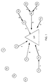
図1は、標準的な無線周波数(RF)メッシュネットワーク100を概略的に示す図である。図1に示すネットワークは、少なくとも1つのアクセスポイントを含む。アクセスポイントは、メッシュネットワーク100と、例えば、ワイドエリアネットワーク(不図示)である別のネットワークとの間のインタフェースとして機能するゲートウェイGWであっても良い。ゲートウェイGWは、送信機と、少なくとも1つの周波数で送信された信号及びより好ましくは複数の周波数で送信された信号を受信できる受信機とを含む。送信機により、ゲートウェイは適切な信号伝播範囲内の他の何らかの送受信機と通信できる。一実施形態において、ゲートウェイは、図1中で記号「Tx」により識別される標準的な単一送信機/単一受信機の送受信機の「海(sea)」により包囲されても良い。例えば、送受信機TXは、ユーティリティネットワーク内のメータノードを表しても良く、例えば、ゲートウェイGWは、ユーティリティネットワーク内のメータノードに関連付けられる種々のバックオフィス機能へのアクセスを提供しても良い。
FIG. 1 schematically illustrates a standard radio frequency (RF)
図1に示すように、ゲートウェイと通信する複数の送受信機が存在しても良い。本実施形態において、送受信機は一度に1つずつゲートウェイへ送信する。これらの送信及びその順番を図1の番号付きの矢印線で示す。実線は、送受信機からゲートウェイへの送信又は互いに中継器として動作する送受信機ノード間の送信のいずれかである正常に受信された送信を示す。正常な各送信の後、ゲートウェイは肯定応答を用いて送出側送受信機に即座に応答する。従って、データパケットがタイムスロット1において受信される場合、ゲートウェイはACKパケットを用いて応答する。その後、別のデータパケットがタイムスロット2において受信される場合、ゲートウェイは当該パケットを送信した送受信機にACKパケットを送出する。ACKパケットは、パケットが送信された個々の送信元ノードに一度に1つずつ送出される。
As shown in FIG. 1, there may be a plurality of transceivers that communicate with the gateway. In this embodiment, the transceiver transmits to the gateway one at a time. These transmissions and their order are indicated by numbered arrow lines in FIG. The solid line indicates a successfully received transmission, either a transmission from a transceiver to a gateway or a transmission between transceiver nodes that act as repeaters with each other. After each successful transmission, the gateway responds immediately to the sending transceiver with an acknowledgment. Thus, if a data packet is received in
図1の破線は失敗を示す。密集して相互接続されたメッシュネットワークにおいて、失敗の原因は2つ考えられる。すなわち、パケットの衝突及び指定受信機が使用不能であることである。パケットの衝突は、2つ以上のノードが同一周波数でほぼ同時に送信したため、それらの各パケットが重複し、いずれの送信も指定受信機で正常に受信されない結果発生しても良い。タイムスロット4において共にゲートウェイに向う破線でこの状態を示す。
The broken line in FIG. 1 indicates failure. There are two possible causes of failure in a densely interconnected mesh network. That is, packet collisions and designated receivers are unusable. The packet collision may occur as a result of two or more nodes transmitting almost simultaneously at the same frequency, so that their respective packets overlap, and neither transmission is normally received by the designated receiver. In
受信機が使用不能であることによる失敗は、指定受信機がパケットを受信するのに必要な時間中に送信周波数において信号を受信できない場合に発生しても良い。この状況は、指定受信機が、例えば、周波数ホッピングプロトコルを採用するネットワーク内の別のノードからパケットを受信するために異なる周波数上に存在する場合に発生しても良い。別の例として、図1中のタイムスロット1を表す線は、ゲートウェイへの正常な(実線)送信及びゲートウェイへの通信中は、オフチャネルである同一受信機に向けた失敗した(破線)送信を示す。
Failure due to unavailability of the receiver may occur when a signal cannot be received at the transmission frequency during the time required for the designated receiver to receive the packet. This situation may occur when the designated receiver is on a different frequency to receive packets from, for example, another node in the network that employs a frequency hopping protocol. As another example, the line representing
これらのアクセス失敗状態は、スケジューリングを介して緩和されても良く、これは、データトラフィックが決定論的である場合に有効であっても良い。データトラフィックが予測不能である場合、例えば、データトラフィックが自律的又は反応的に発生される場合、スケジューリングの効果は低い。 These access failure conditions may be mitigated through scheduling, which may be useful when data traffic is deterministic. If the data traffic is unpredictable, for example if the data traffic is generated autonomously or reactively, the scheduling effect is low.
また、図1に示すように、タイムスロット2において複数の正常な送信が存在しても良い。本明細書中で一実施形態を開示する周波数可変メッシュネットワークにおいて、隣接しないノードは、同一周波数を同時に占有しても良いため、必然的に周波数再利用機能を形成し且つ有する。
Also, as shown in FIG. 1, there may be a plurality of normal transmissions in
図示するように、ゲートウェイに送出されるパケットに通し番号を付与することにより、RFメッシュネットワークにおいて障害を発生させる場合がある。ゲートウェイへの直接リンクを有する各送受信機は、正常に受信されるためにスケジュールされたか又は他と衝突しない一意の時間にメッセージを送出する必要がある。各メッセージの受信後、ゲートウェイは、次のメッセージに移動する前に応答する。一般に、ゲートウェイは、RFメッシュネットワークへの入口及び出口を提供しても良いという点でアーキテクチャがほぼ一意であっても良い。従って、ゲートウェイの受信機及び送信機による制限は、RFメッシュネットワークの性能に影響を及ぼす場合がある。 As shown in the figure, a failure may occur in the RF mesh network by giving a serial number to a packet sent to the gateway. Each transceiver with a direct link to the gateway needs to send a message at a unique time that is scheduled to be successfully received or does not collide with others. After receiving each message, the gateway responds before moving to the next message. In general, the gateway may be nearly unique in architecture in that it may provide entry and exit to the RF mesh network. Thus, limitations due to gateway receivers and transmitters may affect the performance of the RF mesh network.
この問題を解決するため、図2は、マルチチャネルノードの好適な一実施形態における送信を示す。本実施形態において、例えば、ゲートウェイであるノードは、RFメッシュネットワークにおいて同時に複数のチャネルで受信するように構成される。パケットは、時間領域で重複する場合であっても周波数領域で衝突しないように、異なる周波数で送出されても良い。図2に示すように、種々のメッセージがタイムスロット1においてゲートウェイで受信されている。
To solve this problem, FIG. 2 shows transmission in a preferred embodiment of a multi-channel node. In this embodiment, for example, a node that is a gateway is configured to receive on a plurality of channels simultaneously in an RF mesh network. Packets may be sent out at different frequencies so that they do not collide in the frequency domain even if they overlap in the time domain. As shown in FIG. 2, various messages are received at the gateway in
非マルチチャネル装置(例えば、図2に示す送受信機ノードTx)は、送信及び受信を同時に行えない。従って、同時に送信しているノードに向けられた送信は失敗する場合がある。 Non-multichannel devices (eg, transceiver node Tx shown in FIG. 2) cannot perform transmission and reception simultaneously. Thus, transmissions directed to simultaneously transmitting nodes may fail.
入力データパケットを異なる周波数で同時に受信することは周波数スペクトルの衝突防止に有用である。しかし、これにより何らかの可能なACK(送出側ノードに返される)が時間的に衝突する状況になる場合がある。図1の実施形態において、ACKは関連するデータパケットの受信後に即座に送信されるのが理想的である。しかし、図2のマルチチャネルノードの場合、ゲートウェイが受信中に送信できず且つ送信中に受信できないため、データパケットの受信後に即座にACKを送信できない場合がある。 Receiving input data packets simultaneously on different frequencies is useful for preventing frequency spectrum collisions. However, this may lead to situations where some possible ACKs (returned to the sending node) collide in time. In the embodiment of FIG. 1, the ACK is ideally transmitted immediately after receipt of the associated data packet. However, in the case of the multi-channel node of FIG. 2, the gateway cannot transmit during reception and cannot receive during transmission, and therefore may not be able to transmit ACK immediately after receiving a data packet.
図3Aは、ノードにおけるパケットの受信及び肯定応答の一般的なシーケンスを示す。送出側ノードは、パケットがアドレス指定される受信側ノードのアドレス及び送信側ノードのアドレス、並びに送信されるデータを含むデータパケットを送信する。パケットがアドレス指定される例えばゲートウェイであるノードは、送出側のアドレスと受信側のアドレスとを入れ替え且つ肯定応答インディケータを追加することによりACKパケットを作成する。その後、受信側ノードは元の送出側ノードへACKパケットを送信する。 FIG. 3A shows a general sequence of packet reception and acknowledgment at a node. The sending node transmits a data packet including the address of the receiving node to which the packet is addressed, the address of the sending node, and the data to be transmitted. A node, for example a gateway, to which the packet is addressed creates an ACK packet by swapping the sending and receiving addresses and adding an acknowledgment indicator. Thereafter, the receiving node transmits an ACK packet to the original transmitting node.
複数のパケットが同一タイムスロットにおいて異なる周波数で受信される場合、受信側ノードはこの方法でACKパケットを作成して即座に返せない場合がある。この状況を解決するため、ACKは集約又はスタックされ、受信側ノードにより送信される単一応答パケットの一部として一斉に送出される。図3Bは、スタックACKパケットの概念を示す。一実施形態において、送出側ノードは、例えば、図3Aに示す場合と同一のデータパケット形式を使用しても良い。しかし、図3Bの例において、ゲートウェイは、図2の実施形態と同様に、送出側ノードにより複数のチャネルにおいて同時に送信されたパケットを受信するように構成されても良い。図3Bは、N個のデータパケットがゲートウェイで受信される例を示す。これに応答して、単一ACKパケットが作成される。このパケットは、全ノードにより認識される同報通信アドレス及び受信側ノードのアドレスを含む。パケットは、データパケットが正常に受信された送出側ノード1〜Nの各々に対する識別子を更に含む。そのような同報通信パケットの受信に応答して、各ノードはパケット内で自身の識別子を探し、識別子を見つけた場合、パケットをACKパケットとして処理する。 If multiple packets are received at different frequencies in the same time slot, the receiving node may not be able to create an ACK packet in this way and return it immediately. To solve this situation, ACKs are aggregated or stacked and sent together as part of a single response packet sent by the receiving node. FIG. 3B shows the concept of a stack ACK packet. In one embodiment, the sending node may use, for example, the same data packet format as shown in FIG. 3A. However, in the example of FIG. 3B, the gateway may be configured to receive packets sent simultaneously on multiple channels by the sending node, similar to the embodiment of FIG. FIG. 3B shows an example in which N data packets are received at the gateway. In response, a single ACK packet is created. This packet contains the broadcast address recognized by all nodes and the address of the receiving node. The packet further includes an identifier for each of the sending nodes 1-N from which the data packet was successfully received. In response to receiving such a broadcast packet, each node looks for its own identifier in the packet, and if it finds an identifier, treats the packet as an ACK packet.
図3Cは、スタックACKパケットのフレーム構造の好適な一実施形態を示す。本実施形態において、フレームは、同報通信アドレス及び応答側ノードのアドレスの後ろに、このパケットの種類をACKとして識別するフィールドを含む。しかし、このフレームの種類のフィールドは不要であっても良い。例えば、送出側ノードは、特定の時間内に送信先ノードから受信した自身の識別子を含む何らかの同報通信フレームがACKパケットを構成すると認識しても良い。 FIG. 3C shows a preferred embodiment of the frame structure of the stack ACK packet. In this embodiment, the frame includes a field that identifies this packet type as ACK after the broadcast address and the address of the responding node. However, this frame type field may be unnecessary. For example, the sending node may recognize that some broadcast frame containing its own identifier received from the destination node within a specific time constitutes an ACK packet.
「メタACK(meta-ACK)」として以下に示す応答パケットにACKをスタックするいくつかの限定しない方法が存在しても良い。種々の例を以下に示す。
i.メタACKは、データパケットの受信順で挿入された全受信データパケットの送信元の完全な8バイトMACアドレスを含んでも良い。
ii.メタACKは、受信順で挿入された各データパケットの送信元の予め決められた単一バイト又はショートアドレスを有しても良い。ショートアドレスは、ユニキャストパケットに使用される8バイトMACアドレスよりはるかに短い事前割り当てアドレスであっても良い。例えば、ショートアドレスは、完全なMACアドレスの最後のバイト又はMACアドレスのハッシュであっても良い。このアドレスの省略の結果、メタACKのサイズは半分又は1/4になっても良い。
iii.アドレスは、受信順を使用するのではなく、受信パケットに関連付けられる優先順位に基づく優先順に配置されても良い。例えば、優先順位は、障害報告等の送出側ノードが送信している内容の性質又は送出側ノードのシャットダウン前の「最後の」送信に基づいても良い。あるいは、順番は特定の送出側ノードに関連付けられる優先順位に基づいても良い。
iv.アドレスは、送信元ノードの周波数ホッピングパターンの予見等の他の基準を反映した順番で配置可能である。
v.アドレスは、自身のデータが受信されたかをリスニングノードがメタACKにおいて早い段階で判定できるように数値順で配置可能である。例えば、リスニングノードがショートアドレス5を割り当てられ且つアドレス2、3、7等を受信する場合、リスニングノードは自身のACKがメタACK内に存在しないと判定しても良い。アドレス7を受信した時点で、ノードは自身に対するACKが存在しないため、自身のデータパケットが受信されなかったと判定できる。
There may be several non-limiting methods of stacking ACKs in response packets shown below as “meta-ACK”. Various examples are shown below.
i. The meta ACK may include the complete 8-byte MAC address of the source of all received data packets inserted in the order in which the data packets are received.
ii. The meta ACK may have a predetermined single byte or short address of the transmission source of each data packet inserted in the order of reception. The short address may be a pre-assigned address that is much shorter than the 8-byte MAC address used for unicast packets. For example, the short address may be the last byte of the complete MAC address or a hash of the MAC address. As a result of omitting this address, the size of the meta ACK may be halved or ¼.
iii. The addresses may be arranged in the priority order based on the priority order associated with the received packet, instead of using the reception order. For example, the priority may be based on the nature of the content being sent by the sending node, such as a failure report, or the “last” transmission before the sending node is shut down. Alternatively, the order may be based on the priority associated with a particular sending node.
iv. The addresses can be arranged in an order that reflects other criteria such as a prediction of the frequency hopping pattern of the source node.
v. The addresses can be arranged in numerical order so that the listening node can determine at an early stage in the meta ACK whether its own data has been received. For example, if the listening node is assigned
いくつかの例において、入力される要求に対する応答を実行するのに相当な時間がかかる場合があり、これは、そのような要求を受信する使用中のAPにおいて障害が発生する一因となる。そのような要求の例は、ノードの実行可能なコードイメージの更新に対する要求、ノードルーティングテーブル情報に対する要求、セキュリティ警告(例えば、認証を確認できないノードの識別)、タイミング情報(ドリフト率及び絶対時間又は周波数)に対する要求等を含む。一実施形態において、これらの種類の要求は、それらを処理する能力がより高い異なるノードに委ねられても良い。異なるノードに委ねるため、要求を受信したマルチチャネルAPは、応答を用意する際に、要求を実行するために異なるノードへ進むように送信元ノードに命令するコマンドをスタック応答のセットに含めても良い。このコマンドを受信した場合、送信元ノードは、コマンドにおいて識別された他のノードをアドレス指定した要求を再送出する。 In some examples, it may take a considerable amount of time to perform a response to an incoming request, which contributes to a failure at the busy AP that receives such a request. Examples of such requests include a request for an update of a node's executable code image, a request for node routing table information, a security warning (eg, identification of a node that cannot verify authentication), timing information (drift rate and absolute time or Frequency)). In one embodiment, these types of requests may be delegated to different nodes that are more capable of processing them. In order to delegate to different nodes, the multi-channel AP that received the request may include a command in the stack response set that instructs the source node to proceed to a different node to execute the request when preparing the response. good. If this command is received, the source node resends a request addressing another node identified in the command.
要求を転送される他のノードは、終端ノードの異なるクラスを処理するために確立される別のマルチチャネル受信側ノードであっても良い。これは、例えば、ユーティリティネットワーム内の配電自動化(DA:Distribution Automation)ノードをサポートするために別個のインフラストラクチャが配置される場合に当てはまっても良い。DAノードが電源回路網の接続性を切り替え且つ制御するノードであるため、それらは消費を監視するメータと関連付けられるノードよりユーティリティに対する優先順位が高い。従って、DAインフラストラクチャは、それらDAノードに対するより高速、高信頼又は高セキュリティの通信を提供するように設計されたポリシーを実行するために部分的に「分離状態」であるように維持可能である。 The other node to which the request is forwarded may be another multi-channel receiver node established to handle different classes of end nodes. This may be the case, for example, when a separate infrastructure is deployed to support a Distribution Automation (DA) node in a utility network. Since DA nodes are nodes that switch and control the connectivity of the power supply network, they have higher priority for utilities than nodes associated with meters that monitor consumption. Thus, the DA infrastructure can be maintained to be partially “isolated” to enforce policies designed to provide faster, more reliable or higher security communications for those DA nodes. .
要求が特定の送信元ノードを意図するデータを含むため、上述のコマンド機能等のACK以外のスタック応答は異なるフレーム形式を必要とする。一実施形態において、この種類のスタック応答は、種類−長さ−値(TLV)要素を含むデータパケットを介して実現されても良い。データ通信プロトコルにおいて、オプションの情報がTLV要素としてプロトコル内に埋め込まれても良い。各TLV要素は以下のフィールドを含む。
種類:メッセージのこの要素がコマンド等を示すフィールドの種類を示す数値コード。
長さ:値フィールドのサイズ(通常は、バイト単位)。
値:コマンド自体等、メッセージのこのTLV要素に対するデータを含むサイズ変更可能なバイトのセット。
種類フィールド及び長さフィールドのサイズは固定されても良い(通常は、1〜4バイト)。一方、送信されるデータを収容するため、値フィールドのサイズは可変である。
Since the request includes data intended for a specific source node, stack responses other than ACK such as the command function described above require different frame formats. In one embodiment, this type of stack response may be implemented via a data packet that includes a type-length-value (TLV) element. In the data communication protocol, optional information may be embedded in the protocol as a TLV element. Each TLV element includes the following fields:
Type: A numeric code indicating the type of field in which this element of the message indicates a command or the like.
Length: The size of the value field (usually in bytes).
Value: A resizable set of bytes containing data for this TLV element of the message, such as the command itself.
The size of the type field and the length field may be fixed (usually 1 to 4 bytes). On the other hand, the size of the value field is variable to accommodate the data to be transmitted.
TLV要素を採用するスタック応答フレームの形式の例を図3Dに示す。図3CのスタックACKフレームと同様に、最初の3つのフィールドは、同報通信アドレス、応答を送出する例えばゲートウェイであるマルチチャネルノードのアドレス及び本実施形態では「TLV」であるフレームの種類を含む。フレームのペイロード部分は、例えば、ショートアドレスである要求側ノードの一連の識別子S1、S2、...SNを含み、各識別子の直後に対応するノードに対するTLVを含む。この種類のフレームを構文解析する場合、ノードは、それが自身のものであるかを判定するために最初の識別子を確認する。自身のものではない場合、ノードは、識別子に後続し且つ連続する次の識別子に対するオフセットを提供するTLVの長さフィールドを調べる。この処理は、ノードが自身の特定の識別子を認識するか又はフレームの終端に到達するまで続行される。自身の識別子に一致する識別子を見つけると、ノードは、その識別子に後続するTLV要素全体を調べ、スタックフレームでそれに送出された応答を取得する。 An example format for a stack response frame that employs TLV elements is shown in FIG. 3D. Similar to the stack ACK frame of FIG. 3C, the first three fields include the broadcast address, the address of the multi-channel node that is sending the response, eg, a multi-channel node, and the frame type that is “TLV” in this embodiment. . The payload portion of the frame includes, for example, a series of identifiers S1, S2,. . . SN, and TLV for the corresponding node immediately after each identifier. When parsing this kind of frame, the node checks the first identifier to determine if it is its own. If not, the node examines the length field of the TLV that provides an offset to the next identifier that follows the identifier and continues. This process continues until the node recognizes its specific identifier or reaches the end of the frame. When it finds an identifier that matches its own identifier, the node examines the entire TLV element that follows that identifier and gets the response sent to it in the stack frame.
一実施形態において、ゲートウェイは、何らかの種類のネットワーク構成情報を含むTLVのセットを送出できる。この情報は、例えば、ゲートウェイの広域にルーティング可能なIPv6接頭辞、ゲートウェイのMACアドレス、DNSサーバアドレス、ルーティングの更新、ネットワークタイミング情報及びOSIモデルのレイヤ2/レイヤ3のルーティングに関する他の何らかの変数を含んでも良い。
In one embodiment, the gateway can send a set of TLVs containing some type of network configuration information. This information includes, for example, the IPv6 prefix routable to the gateway's wide area, the gateway's MAC address, DNS server address, routing updates, network timing information, and some other variables related to
なお、メタACKとビーコンパケットとの間には違いが存在する場合がある。例えば、従来の同報通信に含まれる情報は、通常は、特定のノードを宛先としない。すなわち、情報は、送信側ノードに関するものであり、範囲内のあらゆる受信機に配布される。例として、ビーコンのフレーム形式を以下に示す。

ビーコンメッセージと同様に、メタACKは同報通信送信先アドレスを有する。あるいは、より効率的に、同報通信の種類が黙示的であるがフレームの種類がACKである場合、メタACKは送信先アドレスを有さない。本実施形態において、(1)メタACKの周波数をリスニングしており且つ(2)データを最近送信したノードは、このメタACKに関心を持つ。従って、メタACK内のデータは、送信側ノードではなく、データ送出元に関する。 Similar to the beacon message, the meta ACK has a broadcast destination address. Alternatively, more efficiently, if the broadcast type is implicit but the frame type is ACK, the meta ACK does not have a destination address. In the present embodiment, (1) the node that is listening to the frequency of the meta ACK and (2) has recently transmitted data is interested in this meta ACK. Therefore, the data in the meta ACK relates to the data transmission source, not the transmission side node.
マルチチャネルノードは、種々の方法で実現可能である。例えば、マルチチャネルノードは、単一の送信機及び複数の受信機から構成されても良い。それらの受信機の各々は、通信が受信されても良い異なる周波数に同調される。ハードウェアの使用量が少ないためより安価である別の手法は、同時に受信される複数の信号を区別するためにデジタル信号プロセッサ(DSP)を採用できる。図4A及び図4Bは、上記の後者の実現に基づくマルチチャネルノードのシステムの一例を示す図である。 Multi-channel nodes can be implemented in various ways. For example, a multi-channel node may be composed of a single transmitter and multiple receivers. Each of these receivers is tuned to a different frequency from which communications may be received. Another approach that is less expensive due to less hardware usage can employ a digital signal processor (DSP) to distinguish between multiple signals received simultaneously. 4A and 4B are diagrams illustrating an example of a multi-channel node system based on the latter implementation described above.
マルチチャネルゲートウェイの受信部の一例を示す図4Aを参照すると、ノードにより異なるチャネル、すなわち、異なる搬送周波数で同時に送信される複数のRF信号はアンテナ10で受信され、不要な信号及び他のノイズから所望の周波数の信号を分離するために適切な増幅11、並びにフィルタリング12、13及び14が実行される。一実施形態において、アンテナ10は900MHz周辺の無許可帯域のRF信号を受信するように構成されても良い。その後、フィルタリングされた信号は、A/Dコンバータ15においてデジタル信号に変換され、その結果得られたデジタル信号はDSP16に供給される。DSP16への入力は、異なるチャネルにおいて同時に受信された全ての送信信号の組み合わせを含んでも良い。DSPは、この組み合わせを個別の信号に分離するように動作する。DSPエンジンの出力は、正常な状態に戻されたバイナリデータであり、これらは隣接するプロセッサ(不図示)のプロトコルプロセッサに提示するためにインデックス及び通し番号を付与されても良い。市販のDSPの一例としては、カリフォルニア州のSan JoseのXilinx社により製造されるSPARTANシリーズのフィールドプログラマブルゲートアレイDSPが挙げられる。
Referring to FIG. 4A showing an example of a receiving unit of a multi-channel gateway, a plurality of RF signals transmitted simultaneously on different channels, i.e., different carrier frequencies, are received by an
一実施形態において、図4Aに示すマルチチャネルシステムの例が、DSPエンジンを用いて処理するため、ベースバンドに対する相対的に大きな(マルチチャネル)スペクトルを処理できる。DSP14は、高速フーリエ変換(FFT:Fast Fourier Transform)技術を使用して、逓減されたスペクトル内の多くのチャネルの各々に対するFFTビン(bin)を作成する。一実施形態において、最大で240個のチャネルが存在しても良い。900MHz周辺の搬送周波数を使用する一実施形態において、約83個のチャネルが存在しても良い。実際は、これらのビンは、各チャネルに対する別個の受信機として動作しても良い。各チャネルにおける受信データは、それが正常に受信されたパケットを構成するかを判定するために別個に処理される。受信データが正常に受信されたパケットを構成する場合、ACK又は他の適切な応答が同時に受信された他のパケットに対する応答と共に累積するために用意され、メタACK又はスタック応答を含む他の同様のパケットで返される。
In one embodiment, the example multi-channel system shown in FIG. 4A processes using a DSP engine, so it can process a relatively large (multi-channel) spectrum relative to baseband. The
図4Bは、マルチチャネルゲートウェイのマルチチャネル送信部の一例を示す。図4Aの受信部で使用されたのと同様の構成要素は、送信部において同様に使用可能である。更に、受信DSPにおいて使用されたデジタル処理ソフトウェアは送信DSPにおいて使用されても良い。例えば、受信DSPは、FFTソフトウェアを使用しても良く、送信DSPは逆FFTソフトウェアを使用しても良い。 FIG. 4B shows an example of the multi-channel transmission unit of the multi-channel gateway. Components similar to those used in the receiver of FIG. 4A can be used in the transmitter as well. Furthermore, the digital processing software used in the receiving DSP may be used in the sending DSP. For example, the receiving DSP may use FFT software, and the transmitting DSP may use inverse FFT software.
送信部の例において、複数の送信信号は、DSPにおいてフーリエ係数を構成することにより作成されても良い。これは、デジタル信号処理の当業者には既知である。例えば、振幅係数が0に設定される場合、エネルギーはそのチャネル又は周波数において出力されない。振幅係数が0.25に設定され且つ3つの他の係数が同様に0.25に設定される場合、長さの等しい4つの信号が生成されても良い。振幅係数は、特定のチャネルにおいて宛先とされるノードまでの所定の信号パスを充分に範囲に含むために必要であると推定される信号エネルギーに基づいて確立されても良い。 In the example of the transmission unit, the plurality of transmission signals may be created by configuring Fourier coefficients in the DSP. This is known to those skilled in the art of digital signal processing. For example, if the amplitude factor is set to 0, no energy is output on that channel or frequency. If the amplitude coefficient is set to 0.25 and the three other coefficients are similarly set to 0.25, four signals of equal length may be generated. The amplitude factor may be established based on the signal energy estimated to be necessary to sufficiently cover a given signal path to the destination node in a particular channel.
図5は、一実施形態に係るマルチチャネルアクセスポイントに対するタイミングシーケンスの一例を示す図である。メッシュネットワークの一例において、データは、例えば、100kbpsで送信されても良く、これは約10バイト/msである。この対応を適用すると、本実施形態においては、500バイトのような大きいデータパケットの送信には50msが必要であり、例えば、1500バイトのようなより大きいパケットの送信には150msが必要である。 FIG. 5 is a diagram illustrating an example of a timing sequence for a multi-channel access point according to an embodiment. In one example of a mesh network, data may be transmitted at, for example, 100 kbps, which is about 10 bytes / ms. When this correspondence is applied, 50 ms is required for transmission of a large data packet such as 500 bytes in this embodiment, and 150 ms is required for transmission of a larger packet such as 1500 bytes.
図5に示すように、メッシュネットワークの一例における1秒、すなわち、1000msは、例えば、200msのスロットに分割されても良く、それらは、アクセスポイントへのインバウンドデータのための150msのサブスロット及びアクセスポイントからのアウトバウンドデータのための50msのサブスロットに更に分割されても良い。 As shown in FIG. 5, one second in an example mesh network, ie 1000 ms, may be divided into, for example, 200 ms slots, which are 150 ms subslots and access for inbound data to the access point. It may be further divided into 50 ms subslots for outbound data from the points.
従って、図5に示すタイミングシーケンスの構成例は、各秒が5つのマルチノード交換スロットを含んでも良いことを示す。例えば、ノード1〜4は、200msスロットのうちの150msのインバウンドサブスロットの間にアクセスポイントに別個の周波数で同時に通信しても良い。アクセスポイントは、50msのアウトバウンドサブスロットの間にノード1〜4から正常に受信された各通信に対する応答を送信しても良い。本実施形態において示すように、マルチチャネルアクセスポイントからノード1〜4の各々への応答は、アクセスポイントにより送出される単一メッセージの一部であっても良い。同様のシーケンスは、他の200msのスロットの間に続行しても良い。本実施形態において、例えば、アクセスポイントであるマルチチャネルノードは、200ms毎に応答パケットを送信する。このパケットは、200msのスロットのインバウンドサブスロットの間に正常に受信された全てのインバウンドパケットに対する例えばACKであるスタック応答を含む。
Accordingly, the example timing sequence configuration shown in FIG. 5 indicates that each second may include five multi-node exchange slots. For example, nodes 1-4 may simultaneously communicate to the access point on separate frequencies during a 150 ms inbound subslot of the 200 ms slots. The access point may send a response for each communication successfully received from nodes 1-4 during the 50 ms outbound subslot. As shown in this embodiment, the response from the multi-channel access point to each of the
いくつかのノードは、マルチチャネルアクセスポイントにデータを出力中であっても良く、データを受信中の他のノードは、アクセスポイントへ送信できない。そのため、ノードは、データを交互に出力した後に更なるデータを周期的に受信する2つのグループを自然と形成すると考えられる。図6A及び図6Bは、これらのパケット出力サイクルの例を示す。 Some nodes may be outputting data to the multi-channel access point, and other nodes receiving data cannot transmit to the access point. Therefore, it is considered that the node naturally forms two groups that receive additional data periodically after alternately outputting data. 6A and 6B show examples of these packet output cycles.
図6Aを参照すると、フレーム1は、APに隣接する「2」で示すデータ保持ノードによりAPに出力されるパケットの一例を示す。APに隣接するノードは、APと直接通信できても良い。これらのデータ出力側ノードはグループAの一部である。APに隣接するが転送するデータを有さない「3」で示す他のノードは、例えば、APに隣接せずメッシュネットワーク内で更に遠くに存在するノード4からデータを受信する。ノード3及び4はグループBの一部である。
Referring to FIG. 6A,
フレーム2は、データパケットを出力したノードに送出される肯定応答を示す。本実施形態において、グループAに対して、APは、APにデータを送出した1つ又は複数のノード2にACK又はスタックACKを送出する。グループBに対して、ACKは、データを受信したノード3により送出側ノード4に送出されても良い。
フレーム3は、グループBのノードからのデータがAPに出力され、よりリモートのグループAのノード1からのデータがAPに隣接するノード2に出力される一例を示す。
フレーム4は、フレーム2と同様のACK処理を示す。しかし、本実施形態において、APはグループBの隣接ノード3にACK又はスタックACKを送出し、グループAに対して、ACKはAPに隣接するノード2により送出されても良い。
図6Bは、図5に示したのと同様のタイミングシーケンスにおけるグループA及びグループBのパケット出力サイクルの一例を示す。図6Bは、インバウンドデータ用タイムサブスロットの間にAPにおいて複数のチャネルで受信されるグループAのノードからのデータ及びアウトバウンドデータ用タイムサブスロットの間の後続のACK又はスタックACKの送信を示す。グループAのタイムスロットの後、同様の処理がグループBのノードに対して行われる。 FIG. 6B shows an example of the packet output cycle of group A and group B in the same timing sequence as shown in FIG. FIG. 6B shows transmission of data from a group A node received on multiple channels at an AP during an inbound data time subslot and a subsequent ACK or stack ACK during the outbound data time subslot. After the group A time slot, a similar process is performed on the group B nodes.
一実施形態において、上述のタイミングシーケンスに対するタイミング同期を伝達するため、ビーコンパケットが使用されても良い。ビーコンパケットは、データパケットを受信可能な時間及びチャネル、並びに対応するACKが送出される時間及びチャネルを示すためにマルチチャネルノードにより送出されても良い。これらのビーコンパケットは事前に指定された時間に送出されても良く、例えば、マルチチャネルノードに直ぐ隣接するノードであるマルチチャネル受信側ノードの直接範囲内の全てのノードにより利用可能であっても良い。 In one embodiment, beacon packets may be used to convey timing synchronization for the timing sequence described above. A beacon packet may be sent by a multi-channel node to indicate the time and channel at which a data packet can be received and the time and channel at which the corresponding ACK is sent. These beacon packets may be sent at a pre-specified time, for example, even if they can be used by all nodes within the direct range of a multi-channel receiving node that is a node immediately adjacent to the multi-channel node. good.
元のデータパケットの送出元がACKを受信しない場合、以下の理由のいずれかが考えられる。
1)最初からマルチチャネル受信側ノードがデータパケットを受信しなかった。
2)ACKが元のデータの送出元により正常に受信されなかった。
いずれの場合も、元のデータパケットの送出元は、別の時間及び別のチャネルにおいてデータを再送出しても良い。そのような動作は、後続のデータ送信の成功可能性を向上するために行われても良い。
When the transmission source of the original data packet does not receive ACK, one of the following reasons can be considered.
1) The multi-channel receiving node did not receive a data packet from the beginning.
2) The ACK was not properly received by the sender of the original data.
In either case, the source of the original data packet may retransmit the data at another time and another channel. Such an operation may be performed to improve the success probability of subsequent data transmission.
要求の送出元がACKの受信に失敗した場合、要求が再送出されても良い。この追加の要求は、マルチチャネル受信側ノードがACKを再送出するが、宛先ノードに再送出パケット内の要求を転送しないことにより管理されても良い。あるいは、宛先ノードは、マルチチャネル受信側ノードにより転送された際に重複する要求を削除するように動作しても良い。 If the request source fails to receive the ACK, the request may be retransmitted. This additional request may be managed by the multi-channel receiving node resending the ACK but not forwarding the request in the resent packet to the destination node. Alternatively, the destination node may operate to delete duplicate requests when transferred by the multi-channel receiver node.
図7は、マルチチャネルアクセスポイントを有するメッシュネットワークの処理の一例を示すフローチャートである。ステップS1において、ノードは、例えば、ビーコンパケットによりノードに伝達されたシーケンスに従って、所定の時間に所定のチャネルをリスニングする。 FIG. 7 is a flowchart illustrating an example of processing of a mesh network having a multi-channel access point. In step S1, the node listens to a predetermined channel at a predetermined time, for example, according to a sequence transmitted to the node by a beacon packet.
ステップS2において、データが受信されない場合、ノードは、所定のチャネル及びタイミングシーケンスに従う動作に戻る。 If no data is received in step S2, the node returns to operation according to a predetermined channel and timing sequence.
データを受信した場合、ステップS3へ進む。ステップS3において、ノードは、単一チャネルノード又はマルチチャネルノードに受信データを転送するかを判定する。マルチチャネルノードにデータを転送しないと判定される場合、データは、例えば、標準的な半二重MACプロトコルを使用して送出されても良い。 If data is received, the process proceeds to step S3. In step S3, the node determines whether to transfer the received data to a single channel node or a multi-channel node. If it is determined not to transfer data to the multi-channel node, the data may be sent using a standard half-duplex MAC protocol, for example.
ステップS4において、データがマルチチャネルノードに送出される場合、データの送信後、送出側ノードは、その特定のACKを待つために所定のスタックACKチャネルに移動しても良い。上述のように、スタックACKを受信するためのチャネル及びタイミングはビーコンパケットにより伝達されても良い。 In step S4, if data is sent to the multi-channel node, after sending the data, the sending node may move to a predetermined stack ACK channel to wait for that particular ACK. As described above, the channel and timing for receiving the stack ACK may be conveyed by a beacon packet.
ステップS5において、元の送出側ノードは、ACKが特定のデータ送信に対して受信されたかを判定する。ACKが受信された場合はステップS1に戻り、上述のように処理を進めても良い。ACKが受信されない場合はステップS3に戻り、ノードはマルチチャネルノードにデータを再送出しても良く、その後、ACKをリスニングするためにステップS4へ進んでも良い。 In step S5, the original sending node determines whether an ACK has been received for a particular data transmission. If ACK is received, the process may return to step S1 and proceed as described above. If no ACK is received, the process returns to step S3, and the node may retransmit the data to the multi-channel node, and then proceed to step S4 to listen for the ACK.
一実施形態において、47 CFR 15.247に対する認証基準を満たすため、APは一度に1つのパケットのみを送出しても良いが、APが同時に受信できるパケット数は限定されなくても良い。従って、一実施形態において、どのノードもAPが受信してもできる可能性のあるいずれかのチャネルでパケットを送出しても良い。別の実施形態において、これは特定のシステムにおいて使用可能な全チャネルである。従って、例えば、センサ又は他の処理制御装置である多くのエンドポイントを有するメッシュネットワークにおいて、本明細書中で説明される好適な実施形態は、例えば、パケットを受信するためのインバウンド方向のハードウェア/ソフトウェアの利用可能性である既知のシステムの制限の影響を軽減しても良い。 In one embodiment, the AP may send only one packet at a time to meet the authentication criteria for 47 CFR 15.247, but the number of packets that the AP can receive simultaneously may not be limited. Thus, in one embodiment, any node may send a packet on any channel that the AP may be able to receive. In another embodiment, this is all channels available in a particular system. Thus, for example, in a mesh network having many endpoints, such as sensors or other processing controllers, the preferred embodiments described herein are for example inbound direction hardware for receiving packets. / The impact of known system limitations that are software availability may be mitigated.
APは、無線伝播範囲内のパケットを受信し、その正当性を確認し、応答パケットであるACKを作成しても良い。一実施形態において、肯定応答されないことが明示的に要求されない限り、受信されたパケットは肯定応答される。別の実施形態は、何らかの優先順位、あるいは順番により情報を伝達するか又は効率を向上する他の方式による肯定応答データの順番付けを含んでも良い。このメタパケットは、既知のスロット、すなわち周波数/時間の組み合わせで送出されても良く、標準的なパケット交換のマルチパケットハンドシェイクを完了するために使用されても良い。 The AP may receive a packet within the radio propagation range, confirm its validity, and create an ACK that is a response packet. In one embodiment, received packets are acknowledged unless explicitly requested not to be acknowledged. Another embodiment may include ordering of acknowledgment data in some priority or other manner that conveys information in order or improves efficiency. This metapacket may be sent in a known slot, ie frequency / time combination, and may be used to complete a standard packet-switched multi-packet handshake.
上記の説明は、当業者が本明細書中で説明されるシステム及び方法を実行及び使用できるようにするために提示され、特定の用途及びその要件において行われる。実施形態に対する種々の変更は当業者には容易に明らかとなるであろう。本明細書中で定義される一般的な原理は、請求の範囲の趣旨の範囲から逸脱することなく他の実施形態及び用途に適用されても良い。従って、図示された実施形態に限定されることを意図せず、本明細書中で開示された原理及び特徴と一致するように広範に解釈されるべきである。 The above description is presented to enable one of ordinary skill in the art to make and use the systems and methods described herein and is made in a particular application and its requirements. Various modifications to the embodiments will be readily apparent to those skilled in the art. The general principles defined herein may be applied to other embodiments and applications without departing from the scope of the claims. Accordingly, it is not intended to be limited to the illustrated embodiments, but is to be construed broadly to be consistent with the principles and features disclosed herein.
Claims (39)
第2のノードにより複数のチャネル各々において複数の第1のノードの各々から通信を受信するステップと、
前記複数の第1のノードの各々から正常に受信された各通信に対する応答を含む送信を前記第2のノードにより送出するステップと
を含み、
前記複数の第1のノードの各々に対する前記応答は、前記第2のノードにより送出される単一メッセージの一部であり、
前記単一メッセージ内の前記応答の少なくとも1つは、前記ネットワークにおける前記第1のノードの動作の設定を変更するために、前記第1のノードの少なくとも1つにより使用可能な情報を含み、
前記第1のノードは、少なくとも2つのグループに分割され、
第1のグループにおいて前記第2のノードに隣接する第1のノードは、前記第2のノードと直接通信し、
第2のグループにおいて前記第2のノードに隣接する第1のノードは、他の第1のノードと通信し、
前記第1のグループが前記第2のノードとの通信を完了すると、前記第2のグループにおいて前記第2のノードに隣接する第1のノードは、前記第2のノードと直接通信し、前記第1のグループにおいて前記第2のノードに隣接する第1のノードは、他の第1のノードと通信し、
前記通信は、前記第1のノードの少なくとも1つにより送出された要求を含み、
前記応答は、別のノードに前記要求を送出するように前記少なくとも1つの第1のノードに命令するコマンドを含む
ことを特徴とする方法。 A method of communicating in a network,
Receiving communication from each of a plurality of first nodes in each of a plurality of channels by a second node;
Sending a transmission including a response to each communication successfully received from each of the plurality of first nodes by the second node;
The response to each of the plurality of first nodes is part of a single message sent by the second node;
At least one of the responses in the single message includes information usable by at least one of the first nodes to change a setting of operation of the first node in the network;
The first node is divided into at least two groups;
A first node adjacent to the second node in a first group communicates directly with the second node;
A first node adjacent to the second node in a second group communicates with another first node;
When the first group completes communication with the second node, a first node adjacent to the second node in the second group communicates directly with the second node; A first node adjacent to the second node in one group communicates with another first node ;
The communication includes a request sent by at least one of the first nodes;
The response includes a command that instructs the at least one first node to send the request to another node .
ことを特徴とする請求項1記載の方法。 The method of claim 1, wherein the communication from each of the plurality of first nodes to the second node includes a data packet having a source and destination identification header.
ことを特徴とする請求項1記載の方法。 The method of claim 1, wherein each response from the second node to the plurality of first nodes includes an acknowledgment.
ことを特徴とする請求項1記載の方法。 The message sent by the second node includes an identifier corresponding to each communication of the plurality of first nodes normally received by the second node. The method described.
ことを特徴とする請求項4記載の方法。 The method of claim 4, wherein each identifier comprises an 8-byte MAC address.
ことを特徴とする請求項4記載の方法。 The method of claim 4, wherein each identifier comprises an address shorter than an 8-byte MAC address.
ことを特徴とする請求項4記載の方法。 The method of claim 4, wherein the identifiers are arranged in the message in an order based on the order in which the communications from the first node were received.
ことを特徴とする請求項4記載の方法。 The method of claim 4, wherein the identifiers are arranged in the message in an order based on the numerical value of each identifier.
ことを特徴とする請求項4記載の方法。 The method of claim 4, wherein the identifier is arranged in the message according to a priority based on content associated with the communication from each of the plurality of first nodes.
ことを特徴とする請求項4記載の方法。 The method of claim 4, wherein the identifier is arranged in the message according to a priority based on a source of the communication from each of the plurality of first nodes.
正常に受信されたパケットを送出した前記複数の第1のノードの各々に対応するMACアドレスよりも短い事前割り当てアドレスに基づいて前記送信において順番付けられる
ことを特徴とする請求項1記載の方法。 Each response from the second node to the plurality of first nodes is:
The method of claim 1, wherein the transmissions are ordered based on a pre-assigned address that is shorter than a MAC address corresponding to each of the plurality of first nodes that sent successfully received packets.
正常に受信されたパケットを送出した前記複数の第1のノードの各々に対応する前記MACアドレスの所定のバイトである
ことを特徴とする請求項11記載の方法。 The pre-assigned address is
The method according to claim 11, wherein the MAC address is a predetermined byte corresponding to each of the plurality of first nodes that have transmitted a normally received packet.
正常に受信されたパケットを送出した前記複数の第1のノードの各々に対応する前記MACアドレスのハッシュである
ことを特徴とする請求項11記載の方法。 The pre-assigned address is
The method according to claim 11, wherein the hash is a hash of the MAC address corresponding to each of the plurality of first nodes that sent a normally received packet.
受信パケットに関連付けられる優先順位に基づいて前記送信において順番付けられる
ことを特徴とする請求項1記載の方法。 Each response from the second node to the plurality of first nodes is:
The method of claim 1, wherein the transmissions are ordered based on a priority associated with a received packet.
前記受信パケットの内容に関連付けられる優先順位に基づいて前記送信において順番付けられる
ことを特徴とする請求項14記載の方法。 Each response from the second node to the plurality of first nodes is:
The method of claim 14, wherein the transmissions are ordered based on priorities associated with the contents of the received packets.
前記受信パケットが受信された前記ノードに関連付けられる優先順位に基づいて前記送信において順番付けられる
ことを特徴とする請求項14記載の方法。 Each response from the second node to the plurality of first nodes is:
The method of claim 14, wherein the received packets are ordered in the transmission based on a priority associated with the received node.
前記ネットワークにおける周波数ホッピングパターンに関する情報に基づいて前記送信において順番付けられる
ことを特徴とする請求項1記載の方法。 Each response from the second node to the plurality of first nodes is:
The method of claim 1, wherein the transmissions are ordered based on information about frequency hopping patterns in the network.
ことを特徴とする請求項1記載の方法。 The method of claim 1, wherein the response is included in a data packet in a type-length-value (TLV) format.
ことを特徴とする請求項1記載の方法。 The command type - Length - The method of claim 1, wherein the a value (TLV) format contained in the data packet.
ことを特徴とする請求項1記載の方法。 It said request The method of claim 1, wherein a is for updating the executable code image of a node.
ことを特徴とする請求項1記載の方法。 It said request The method of claim 1, wherein a is for node routing table information.
ことを特徴とする請求項1記載の方法。 It said request The method of claim 1, wherein a is for security alert information.
ことを特徴とする請求項1記載の方法。 It said request The method of claim 1, wherein a is for timing information.
ことを特徴とする請求項1記載の方法。 The method according to claim 1, wherein the transmission of the communication by each of the plurality of first nodes and the transmission of the transmission by the second node are performed during a predetermined time slot.
ことを特徴とする請求項24記載の方法。 The method of claim 24 , wherein sending the communication by each of the plurality of first nodes occurs during a first portion of the predetermined time slot.
ことを特徴とする請求項24記載の方法。 25. The method of claim 24, wherein at least some communication temporal overlap exists between the transmissions on a plurality of channels by each of the plurality of first nodes.
ことを特徴とする請求項25記載の方法。 The method of claim 25 , wherein sending the transmission by the second node occurs during a second portion of the predetermined time slot.
ことを特徴とする請求項24記載の方法。 The method of claim 24 , wherein the information about the predetermined time slot is sent to the first node in a beacon packet.
ことを特徴とする請求項28記載の方法。 The method of claim 28 , wherein the beacon packet includes at least one of timing synchronization information, timing sequence information, and channel information.
第1のノードにより所定の時間に所定のチャネルを監視するステップと、
データが前記所定の時間に前記所定のチャネルにおいて受信されたかを前記第1のノードにより判定するステップと、
データが受信された場合に単一チャネル受信側ノード又はマルチチャネル受信側ノードに受信データを転送するかを前記第1のノードにより判定するステップと、
前記データが前記マルチチャネル受信側ノードに送出されると判定された場合に前記第1のノードにより前記マルチチャネル受信側ノードに前記受信データを送信するステップと、
前記データが前記マルチチャネル受信側ノードへ送信されると、前記第1のノードにより所定の応答チャネルを監視するステップと、
前記所定の応答チャネルを監視することにより、前記第1のノードが前記マルチチャネル受信側ノードにより送信された送信データに対する応答を受信したかを前記第1のノードにより判定するステップと、
前記第1のノードが前記マルチチャネル受信側ノードから応答を受信していないと判定された場合、前記第1のノードにより前記マルチチャネル受信側ノードへ前記データを再送信するステップと
を含み、
前記第1のノードは、少なくとも2つのグループに分割される複数の第1のノードの1つであり、
第1のグループにおいて前記マルチチャネル受信側ノードに隣接する第1のノードは、前記マルチチャネル受信側ノードと直接通信し、
第2のグループにおいて前記マルチチャネル受信側ノードに隣接する第1のノードは、他の第1のノードと通信し、
前記第1のグループが前記マルチチャネル受信側ノードとの通信を完了すると、前記第2のグループにおいて前記マルチチャネル受信側ノードに隣接する第1のノードは、前記マルチチャネル受信側ノードと直接通信し、前記第1のグループにおいて前記マルチチャネル受信側ノードに隣接する第1のノードは、他の第1のノードと通信する
ことを特徴とする方法。 A method of communicating in a network,
Monitoring a predetermined channel at a predetermined time by a first node;
Determining by the first node whether data was received on the predetermined channel at the predetermined time;
Determining by the first node whether to forward received data to a single channel receiver node or a multi-channel receiver node when data is received;
Transmitting the received data by the first node to the multi-channel receiving node when it is determined that the data is sent to the multi-channel receiving node;
When the data is transmitted to the multi-channel receiving node, monitoring a predetermined response channel by the first node;
Determining by the first node whether the first node has received a response to transmission data transmitted by the multi-channel receiving node by monitoring the predetermined response channel;
Retransmitting the data to the multi-channel receiving node by the first node if it is determined that the first node has not received a response from the multi-channel receiving node;
The first node is one of a plurality of first nodes divided into at least two groups;
A first node adjacent to the multi-channel receiver node in a first group communicates directly with the multi-channel receiver node;
A first node adjacent to the multi-channel receiver node in a second group communicates with the other first node;
When the first group completes communication with the multi-channel receiver node, the first node adjacent to the multi-channel receiver node in the second group communicates directly with the multi-channel receiver node. The first node adjacent to the multi-channel receiver node in the first group communicates with another first node.
ことを特徴とする請求項30記載の方法。 31. The method of claim 30, wherein at least one of the predetermined channel, the predetermined time, and the predetermined response channel is provided to the first node by a beacon packet.
ことを特徴とする請求項1記載の方法。 The method of claim 1, wherein the information includes network timing information.
ことを特徴とする請求項1記載の方法。 The method according to claim 1, wherein the information includes at least one variable related to an operation of the at least one first node in at least one of Layer 2 / Layer 3 of a network protocol.
前記コマンドは、該コマンドにより示される特定の動作を実行するように前記少なくとも1つの第1のノードに命令する
ことを特徴とする請求項1記載の方法。 The information includes a command for the at least one first node;
The method of claim 1, wherein the command instructs the at least one first node to perform a specific operation indicated by the command.
ことを特徴とする請求項34記載の方法。 The method of claim 34 , wherein the specific action is an action of causing the at least one first node to retransmit the communication to a different node other than the second node.
ことを特徴とする請求項31記載の方法。 The method of claim 31 , wherein the information is encoded in at least one of a type-length-value (TLV) element in the response of the single message.
ことを特徴とする請求項36記載の方法。 The method of claim 36 , wherein each of the TLV elements corresponds to one of the respective first nodes.
ことを特徴とする請求項37記載の方法。 The method of claim 37 , wherein each type field of a TLV element indicates one of the respective first nodes to which the TLV element corresponds.
第2のノードにより複数のチャネル各々において複数の第1のノードの各々から通信を受信するステップと、
前記複数の第1のノードの各々から正常に受信された各通信に対する応答を含む送信を前記第2のノードにより送出するステップと
を含み、
前記複数の第1のノードの各々に対する前記応答は、前記第2のノードにより送出される単一メッセージの一部であり、
前記単一メッセージ内の前記応答の順番は、
前記複数の第1のノード各々から前記第2のノードにより受信された前記通信に関連付けられる優先順位に対応しており、
前記第1のノードは、少なくとも2つのグループに分割され、
第1のグループにおいて前記第2のノードに隣接する第1のノードは、前記第2のノードと直接通信し、
第2のグループにおいて前記第2のノードに隣接する第1のノードは、他の第1のノードと通信し、
前記第1のグループが前記第2のノードとの通信を完了すると、前記第2のグループにおいて前記第2のノードに隣接する第1のノードは、前記第2のノードと直接通信し、前記第1のグループにおいて前記第2のノードに隣接する第1のノードは、他の第1のノードと通信する
ことを特徴とする方法。 A method of communicating in a network,
Receiving communication from each of a plurality of first nodes in each of a plurality of channels by a second node;
Sending a transmission including a response to each communication successfully received from each of the plurality of first nodes by the second node;
The response to each of the plurality of first nodes is part of a single message sent by the second node;
The order of the responses within the single message is
Corresponding to the priority associated with the communication received by the second node from each of the plurality of first nodes;
The first node is divided into at least two groups;
A first node adjacent to the second node in a first group communicates directly with the second node;
A first node adjacent to the second node in a second group communicates with another first node;
When the first group completes communication with the second node, a first node adjacent to the second node in the second group communicates directly with the second node; A method in which a first node adjacent to the second node in one group communicates with another first node.
Applications Claiming Priority (3)
| Application Number | Priority Date | Filing Date | Title |
|---|---|---|---|
| US12/207,358 US9025584B2 (en) | 2008-09-09 | 2008-09-09 | Multi-channel mesh nodes employing stacked responses |
| US12/207,358 | 2008-09-09 | ||
| PCT/US2009/004855 WO2010030322A2 (en) | 2008-09-09 | 2009-08-26 | Multi-channel mesh nodes employing stacked responses |
Publications (3)
| Publication Number | Publication Date |
|---|---|
| JP2012502551A JP2012502551A (en) | 2012-01-26 |
| JP2012502551A5 JP2012502551A5 (en) | 2012-10-11 |
| JP5587888B2 true JP5587888B2 (en) | 2014-09-10 |
Family
ID=41799225
Family Applications (1)
| Application Number | Title | Priority Date | Filing Date |
|---|---|---|---|
| JP2011526034A Active JP5587888B2 (en) | 2008-09-09 | 2009-08-26 | Multi-channel mesh node with stack response |
Country Status (13)
| Country | Link |
|---|---|
| US (3) | US9025584B2 (en) |
| EP (1) | EP2324590B1 (en) |
| JP (1) | JP5587888B2 (en) |
| KR (1) | KR20110063666A (en) |
| CN (1) | CN102204145A (en) |
| AR (1) | AR073502A1 (en) |
| AU (1) | AU2009292221A1 (en) |
| BR (1) | BRPI0919101A2 (en) |
| CA (1) | CA2736737A1 (en) |
| DK (1) | DK2324590T3 (en) |
| MX (1) | MX2011002569A (en) |
| TW (1) | TW201012251A (en) |
| WO (1) | WO2010030322A2 (en) |
Cited By (1)
| Publication number | Priority date | Publication date | Assignee | Title |
|---|---|---|---|---|
| RU2735232C1 (en) * | 2017-10-27 | 2020-10-29 | Телефонактиеболагет Лм Эрикссон (Пабл) | Method and apparatus for updating the number of retransmissions in a wireless mesh network |
Families Citing this family (39)
| Publication number | Priority date | Publication date | Assignee | Title |
|---|---|---|---|---|
| EP2203911A4 (en) | 2007-10-25 | 2011-12-28 | Trilliant Networks Inc | Gas meter having ultra-sensitive magnetic material retrofitted onto meter dial and method for performing meter retrofit |
| US8332055B2 (en) * | 2007-11-25 | 2012-12-11 | Trilliant Networks, Inc. | Energy use control system and method |
| CA2705091A1 (en) | 2007-11-25 | 2009-05-28 | Trilliant Networks, Inc. | System and method for power outage and restoration notification in an advanced metering infrasturcture network |
| EP2215555A4 (en) | 2007-11-25 | 2011-01-26 | Trilliant Networks Inc | System and method for operating mesh devices in multi-tree overlapping mesh networks |
| US8138934B2 (en) | 2007-11-25 | 2012-03-20 | Trilliant Networks, Inc. | System and method for false alert filtering of event messages within a network |
| EP2321983B1 (en) | 2008-09-04 | 2018-05-09 | Trilliant Networks, Inc. | Method for implementing mesh network communications using a mesh network protocol |
| US8457106B2 (en) * | 2008-09-30 | 2013-06-04 | Electronics And Telecommunications Research Institute | Method for wireless communication in wireless sensor network environment |
| US8289182B2 (en) | 2008-11-21 | 2012-10-16 | Trilliant Networks, Inc. | Methods and systems for virtual energy management display |
| WO2010105038A1 (en) | 2009-03-11 | 2010-09-16 | Trilliant Networks, Inc. | Process, device and system for mapping transformers to meters and locating non-technical line losses |
| JP5312686B2 (en) | 2009-05-07 | 2013-10-09 | ドミニオン リソーシス インク | Voltage management using centralized voltage control at higher measurement infrastructure and substations |
| WO2012027634A1 (en) | 2010-08-27 | 2012-03-01 | Trilliant Networkd, Inc. | System and method for interference free operation of co-located tranceivers |
| CA2813534A1 (en) | 2010-09-13 | 2012-03-22 | Trilliant Networks, Inc. | Process for detecting energy theft |
| US8832428B2 (en) | 2010-11-15 | 2014-09-09 | Trilliant Holdings Inc. | System and method for securely communicating across multiple networks using a single radio |
| JP5604314B2 (en) * | 2011-01-13 | 2014-10-08 | オムロンオートモーティブエレクトロニクス株式会社 | Detection device, detection system, and detection method for radio wave handset |
| US9282383B2 (en) | 2011-01-14 | 2016-03-08 | Trilliant Incorporated | Process, device and system for volt/VAR optimization |
| WO2012103072A2 (en) | 2011-01-25 | 2012-08-02 | Trilliant Holdings, Inc. | Aggregated real-time power outages/restoration reporting (rtpor) in a secure mesh network |
| US9319184B2 (en) * | 2011-02-01 | 2016-04-19 | Qualcomm Incorporated | Multiple wireless communication device acknowledgements |
| WO2012173667A2 (en) | 2011-02-10 | 2012-12-20 | Trilliant Holdings, Inc. | Device and method for facilitating secure communications over a cellular network |
| US9041349B2 (en) | 2011-03-08 | 2015-05-26 | Trilliant Networks, Inc. | System and method for managing load distribution across a power grid |
| US9300442B2 (en) | 2011-07-21 | 2016-03-29 | Qualcomm Incorporated | Allowing a rejected wireless communication device access to a communication channel |
| WO2013025820A2 (en) * | 2011-08-15 | 2013-02-21 | Marvell World Trade Ltd. | Long range wlan data unit format |
| US9001787B1 (en) | 2011-09-20 | 2015-04-07 | Trilliant Networks Inc. | System and method for implementing handover of a hybrid communications module |
| CN106850140B (en) * | 2012-01-12 | 2020-04-28 | 华为终端有限公司 | Data communication method, device and system |
| US9584179B2 (en) * | 2012-02-23 | 2017-02-28 | Silver Spring Networks, Inc. | System and method for multi-channel frequency hopping spread spectrum communication |
| US9563218B2 (en) | 2013-03-15 | 2017-02-07 | Dominion Resources, Inc. | Electric power system control with measurement of energy demand and energy efficiency using t-distributions |
| US9553453B2 (en) | 2013-03-15 | 2017-01-24 | Dominion Resources, Inc. | Management of energy demand and energy efficiency savings from voltage optimization on electric power systems using AMI-based data analysis |
| US9678520B2 (en) | 2013-03-15 | 2017-06-13 | Dominion Resources, Inc. | Electric power system control with planning of energy demand and energy efficiency using AMI-based data analysis |
| US9582020B2 (en) | 2013-03-15 | 2017-02-28 | Dominion Resources, Inc. | Maximizing of energy delivery system compatibility with voltage optimization using AMI-based data control and analysis |
| US9847639B2 (en) | 2013-03-15 | 2017-12-19 | Dominion Energy, Inc. | Electric power system control with measurement of energy demand and energy efficiency |
| CN104378828B (en) * | 2013-08-15 | 2018-03-09 | 华为技术有限公司 | A kind of methods, devices and systems of channel access |
| KR101484059B1 (en) | 2013-09-17 | 2015-01-20 | 성균관대학교산학협력단 | Method and apparatus for high speed wlan using multi-rate aware partitioning and cooperative transmission |
| US10263892B2 (en) * | 2015-03-20 | 2019-04-16 | Microchip Technology Incorporated | Compression method and system for user friendly address in mesh networking |
| EP3098793A1 (en) | 2015-05-26 | 2016-11-30 | Life Safety Distribution AG | Method for configuring a wireless fire detection system |
| JP2018526853A (en) * | 2015-06-22 | 2018-09-13 | ディーエヌジー テクノロジーズ エルティーディー | Smart home system |
| US10015239B1 (en) | 2015-08-12 | 2018-07-03 | Evengx, Llc | Self-organizing distributed computation grid |
| US10732656B2 (en) | 2015-08-24 | 2020-08-04 | Dominion Energy, Inc. | Systems and methods for stabilizer control |
| CN107872300B (en) | 2016-09-28 | 2022-11-04 | 中兴通讯股份有限公司 | Feedback information processing method, device and system, base station and terminal |
| CN108347321A (en) * | 2017-01-25 | 2018-07-31 | 华为技术有限公司 | A kind of communication means and device |
| CN107404377B (en) * | 2017-09-11 | 2020-10-27 | 海能达通信股份有限公司 | Access signal generation method and device and access signal |
Family Cites Families (15)
| Publication number | Priority date | Publication date | Assignee | Title |
|---|---|---|---|---|
| JP4037965B2 (en) * | 1998-08-18 | 2008-01-23 | 富士通株式会社 | Code division multiple access communication system, base station for code division multiple access communication system, terminal apparatus for code division multiple access communication system, code division multiple access communication method, and communication method for terminal apparatus |
| US20050058149A1 (en) * | 1998-08-19 | 2005-03-17 | Howe Wayne Richard | Time-scheduled and time-reservation packet switching |
| US6338092B1 (en) | 1998-09-24 | 2002-01-08 | International Business Machines Corporation | Method, system and computer program for replicating data in a distributed computed environment |
| US7310670B1 (en) * | 2000-04-25 | 2007-12-18 | Thomson Licensing S.A. | Multi-channel power line exchange protocol |
| US7469297B1 (en) * | 2000-08-04 | 2008-12-23 | Intellon Corporation | Mechanism for using a quasi-addressed response to bind to a message requesting the response |
| US7464166B2 (en) * | 2003-04-11 | 2008-12-09 | Telefonaktiebolaget Lm Ericsson (Publ) | Contention-based forwarding with integrated multi-user detection capability |
| US7230951B2 (en) * | 2003-04-16 | 2007-06-12 | Nortel Networks Limited | Policy based mobile IP |
| JP4710321B2 (en) * | 2004-02-02 | 2011-06-29 | ソニー株式会社 | Wireless communication system, wireless communication apparatus, wireless communication method, and computer program |
| TWI261441B (en) | 2004-06-28 | 2006-09-01 | Nokia Corp | Method and apparatus for packet aggregation in a wireless communication network |
| US7466964B2 (en) | 2005-06-29 | 2008-12-16 | Intel Corporation | Wireless communication device and method for coordinated channel access with reduced latency in a wireless network |
| JP2007129726A (en) | 2005-11-04 | 2007-05-24 | Samsung Electronics Co Ltd | Apparatus and method for supporting multilink by grouping multihop in cellular network of multihop relay system |
| US7577449B2 (en) * | 2006-06-29 | 2009-08-18 | Motorola, Inc. | Method and system for coordinating a sleep mode wake-up time |
| JP4790544B2 (en) | 2006-08-31 | 2011-10-12 | 富士通株式会社 | Retransmission control method and relay station apparatus in relay communication system |
| US20080068979A1 (en) | 2006-09-14 | 2008-03-20 | Motorola, Inc. | Adaptive and preemptive scheduling of transmissions |
| EP2086276B1 (en) * | 2008-01-31 | 2016-11-02 | LG Electronics Inc. | Method for signaling back-off information in random access |
-
2008
- 2008-09-09 US US12/207,358 patent/US9025584B2/en active Active
-
2009
- 2009-08-26 KR KR1020117008218A patent/KR20110063666A/en not_active Application Discontinuation
- 2009-08-26 WO PCT/US2009/004855 patent/WO2010030322A2/en active Application Filing
- 2009-08-26 MX MX2011002569A patent/MX2011002569A/en not_active Application Discontinuation
- 2009-08-26 DK DK09789211.1T patent/DK2324590T3/en active
- 2009-08-26 CA CA2736737A patent/CA2736737A1/en not_active Abandoned
- 2009-08-26 CN CN2009801421359A patent/CN102204145A/en active Pending
- 2009-08-26 JP JP2011526034A patent/JP5587888B2/en active Active
- 2009-08-26 BR BRPI0919101A patent/BRPI0919101A2/en not_active IP Right Cessation
- 2009-08-26 AU AU2009292221A patent/AU2009292221A1/en not_active Abandoned
- 2009-08-26 EP EP09789211.1A patent/EP2324590B1/en active Active
- 2009-09-08 AR ARP090103443A patent/AR073502A1/en unknown
- 2009-09-08 TW TW098130211A patent/TW201012251A/en unknown
-
2015
- 2015-04-10 US US14/683,206 patent/US9288712B2/en active Active
-
2016
- 2016-02-12 US US15/042,633 patent/US9838902B2/en active Active
Cited By (2)
| Publication number | Priority date | Publication date | Assignee | Title |
|---|---|---|---|---|
| RU2735232C1 (en) * | 2017-10-27 | 2020-10-29 | Телефонактиеболагет Лм Эрикссон (Пабл) | Method and apparatus for updating the number of retransmissions in a wireless mesh network |
| US11153803B2 (en) | 2017-10-27 | 2021-10-19 | Telefonaktiebolaget Lm Ericsson (Publ) | Method and device for updating the number of retransmissions in a wireless mesh network |
Also Published As
| Publication number | Publication date |
|---|---|
| US9288712B2 (en) | 2016-03-15 |
| CA2736737A1 (en) | 2010-03-18 |
| TW201012251A (en) | 2010-03-16 |
| EP2324590B1 (en) | 2014-11-12 |
| US20160165479A1 (en) | 2016-06-09 |
| US20100061350A1 (en) | 2010-03-11 |
| AU2009292221A1 (en) | 2010-03-18 |
| JP2012502551A (en) | 2012-01-26 |
| EP2324590A2 (en) | 2011-05-25 |
| DK2324590T3 (en) | 2015-01-05 |
| MX2011002569A (en) | 2011-04-07 |
| BRPI0919101A2 (en) | 2019-09-24 |
| WO2010030322A3 (en) | 2010-07-08 |
| CN102204145A (en) | 2011-09-28 |
| KR20110063666A (en) | 2011-06-13 |
| US20150215813A1 (en) | 2015-07-30 |
| US9025584B2 (en) | 2015-05-05 |
| US9838902B2 (en) | 2017-12-05 |
| WO2010030322A2 (en) | 2010-03-18 |
| AR073502A1 (en) | 2010-11-10 |
| AU2009292221A2 (en) | 2011-05-26 |
Similar Documents
| Publication | Publication Date | Title |
|---|---|---|
| JP5587888B2 (en) | Multi-channel mesh node with stack response | |
| US11324038B2 (en) | Communication techniques | |
| JP5265014B2 (en) | Ultra-reliable coordinated wireless communication | |
| US20080170544A1 (en) | Method of transmitting between two nodes | |
| WO2004053940A2 (en) | Multi-channel wireless broadcast protocol for a self-organizing network | |
| WO2003105353A2 (en) | System and method for multicast media access using broadcast transmissions with multiple acknowledgments in an ad-hoc communications network | |
| US8687562B2 (en) | Wireless network enhancements | |
| WO2007008174A1 (en) | Method and system of wireless communication between devices | |
| JP2022191467A (en) | Operating method of communication node in wireless communication network, associated communication node, communication system and storage system | |
| US10375672B2 (en) | Data broadcasting with a prepare-to-broadcast message | |
| JP6397856B2 (en) | Data broadcast using broadcast preparation message | |
| US8917680B2 (en) | System and method for reserving channels for high priority packets | |
| EP2386149B1 (en) | Method and system for communication in a wireless network | |
| US11882479B2 (en) | Wireless LAN communication device and wireless LAN communication method | |
| JP2008211600A (en) | Radio communication system, communication device and method for controlling communication | |
| JP2024072825A (en) | Communication Techniques | |
| WO2003049382A1 (en) | Data transmission |
Legal Events
| Date | Code | Title | Description |
|---|---|---|---|
| A521 | Request for written amendment filed |
Free format text: JAPANESE INTERMEDIATE CODE: A523 Effective date: 20120824 |
|
| A621 | Written request for application examination |
Free format text: JAPANESE INTERMEDIATE CODE: A621 Effective date: 20120824 |
|
| A977 | Report on retrieval |
Free format text: JAPANESE INTERMEDIATE CODE: A971007 Effective date: 20131016 |
|
| A131 | Notification of reasons for refusal |
Free format text: JAPANESE INTERMEDIATE CODE: A131 Effective date: 20131206 |
|
| A521 | Request for written amendment filed |
Free format text: JAPANESE INTERMEDIATE CODE: A523 Effective date: 20140204 |
|
| TRDD | Decision of grant or rejection written | ||
| A01 | Written decision to grant a patent or to grant a registration (utility model) |
Free format text: JAPANESE INTERMEDIATE CODE: A01 Effective date: 20140707 |
|
| A61 | First payment of annual fees (during grant procedure) |
Free format text: JAPANESE INTERMEDIATE CODE: A61 Effective date: 20140724 |
|
| R150 | Certificate of patent or registration of utility model |
Ref document number: 5587888 Country of ref document: JP Free format text: JAPANESE INTERMEDIATE CODE: R150 |
|
| R250 | Receipt of annual fees |
Free format text: JAPANESE INTERMEDIATE CODE: R250 |
|
| R250 | Receipt of annual fees |
Free format text: JAPANESE INTERMEDIATE CODE: R250 |
|
| S533 | Written request for registration of change of name |
Free format text: JAPANESE INTERMEDIATE CODE: R313533 |
|
| R350 | Written notification of registration of transfer |
Free format text: JAPANESE INTERMEDIATE CODE: R350 |
|
| R250 | Receipt of annual fees |
Free format text: JAPANESE INTERMEDIATE CODE: R250 |
|
| R250 | Receipt of annual fees |
Free format text: JAPANESE INTERMEDIATE CODE: R250 |
|
| R250 | Receipt of annual fees |
Free format text: JAPANESE INTERMEDIATE CODE: R250 |
|
| R250 | Receipt of annual fees |
Free format text: JAPANESE INTERMEDIATE CODE: R250 |
|
| R250 | Receipt of annual fees |
Free format text: JAPANESE INTERMEDIATE CODE: R250 |