JP5586532B2 - Nonaqueous electrolyte battery and battery pack - Google Patents
Nonaqueous electrolyte battery and battery pack Download PDFInfo
- Publication number
- JP5586532B2 JP5586532B2 JP2011139202A JP2011139202A JP5586532B2 JP 5586532 B2 JP5586532 B2 JP 5586532B2 JP 2011139202 A JP2011139202 A JP 2011139202A JP 2011139202 A JP2011139202 A JP 2011139202A JP 5586532 B2 JP5586532 B2 JP 5586532B2
- Authority
- JP
- Japan
- Prior art keywords
- negative electrode
- active material
- electrode active
- positive electrode
- oxide
- Prior art date
- Legal status (The legal status is an assumption and is not a legal conclusion. Google has not performed a legal analysis and makes no representation as to the accuracy of the status listed.)
- Expired - Fee Related
Links
Images


Classifications
-
- H—ELECTRICITY
- H01—ELECTRIC ELEMENTS
- H01M—PROCESSES OR MEANS, e.g. BATTERIES, FOR THE DIRECT CONVERSION OF CHEMICAL ENERGY INTO ELECTRICAL ENERGY
- H01M4/00—Electrodes
- H01M4/02—Electrodes composed of, or comprising, active material
- H01M4/36—Selection of substances as active materials, active masses, active liquids
- H01M4/48—Selection of substances as active materials, active masses, active liquids of inorganic oxides or hydroxides
- H01M4/485—Selection of substances as active materials, active masses, active liquids of inorganic oxides or hydroxides of mixed oxides or hydroxides for inserting or intercalating light metals, e.g. LiTi2O4 or LiTi2OxFy
-
- H—ELECTRICITY
- H01—ELECTRIC ELEMENTS
- H01M—PROCESSES OR MEANS, e.g. BATTERIES, FOR THE DIRECT CONVERSION OF CHEMICAL ENERGY INTO ELECTRICAL ENERGY
- H01M4/00—Electrodes
- H01M4/02—Electrodes composed of, or comprising, active material
- H01M4/13—Electrodes for accumulators with non-aqueous electrolyte, e.g. for lithium-accumulators; Processes of manufacture thereof
- H01M4/131—Electrodes based on mixed oxides or hydroxides, or on mixtures of oxides or hydroxides, e.g. LiCoOx
-
- H—ELECTRICITY
- H01—ELECTRIC ELEMENTS
- H01M—PROCESSES OR MEANS, e.g. BATTERIES, FOR THE DIRECT CONVERSION OF CHEMICAL ENERGY INTO ELECTRICAL ENERGY
- H01M4/00—Electrodes
- H01M4/02—Electrodes composed of, or comprising, active material
- H01M4/36—Selection of substances as active materials, active masses, active liquids
- H01M4/362—Composites
-
- H—ELECTRICITY
- H01—ELECTRIC ELEMENTS
- H01M—PROCESSES OR MEANS, e.g. BATTERIES, FOR THE DIRECT CONVERSION OF CHEMICAL ENERGY INTO ELECTRICAL ENERGY
- H01M10/00—Secondary cells; Manufacture thereof
- H01M10/05—Accumulators with non-aqueous electrolyte
- H01M10/052—Li-accumulators
- H01M10/0525—Rocking-chair batteries, i.e. batteries with lithium insertion or intercalation in both electrodes; Lithium-ion batteries
-
- H—ELECTRICITY
- H01—ELECTRIC ELEMENTS
- H01M—PROCESSES OR MEANS, e.g. BATTERIES, FOR THE DIRECT CONVERSION OF CHEMICAL ENERGY INTO ELECTRICAL ENERGY
- H01M4/00—Electrodes
- H01M4/02—Electrodes composed of, or comprising, active material
- H01M4/36—Selection of substances as active materials, active masses, active liquids
- H01M4/48—Selection of substances as active materials, active masses, active liquids of inorganic oxides or hydroxides
- H01M4/52—Selection of substances as active materials, active masses, active liquids of inorganic oxides or hydroxides of nickel, cobalt or iron
- H01M4/525—Selection of substances as active materials, active masses, active liquids of inorganic oxides or hydroxides of nickel, cobalt or iron of mixed oxides or hydroxides containing iron, cobalt or nickel for inserting or intercalating light metals, e.g. LiNiO2, LiCoO2 or LiCoOxFy
-
- Y—GENERAL TAGGING OF NEW TECHNOLOGICAL DEVELOPMENTS; GENERAL TAGGING OF CROSS-SECTIONAL TECHNOLOGIES SPANNING OVER SEVERAL SECTIONS OF THE IPC; TECHNICAL SUBJECTS COVERED BY FORMER USPC CROSS-REFERENCE ART COLLECTIONS [XRACs] AND DIGESTS
- Y02—TECHNOLOGIES OR APPLICATIONS FOR MITIGATION OR ADAPTATION AGAINST CLIMATE CHANGE
- Y02E—REDUCTION OF GREENHOUSE GAS [GHG] EMISSIONS, RELATED TO ENERGY GENERATION, TRANSMISSION OR DISTRIBUTION
- Y02E60/00—Enabling technologies; Technologies with a potential or indirect contribution to GHG emissions mitigation
- Y02E60/10—Energy storage using batteries
Landscapes
- Chemical & Material Sciences (AREA)
- Chemical Kinetics & Catalysis (AREA)
- Electrochemistry (AREA)
- General Chemical & Material Sciences (AREA)
- Inorganic Chemistry (AREA)
- Composite Materials (AREA)
- Engineering & Computer Science (AREA)
- Materials Engineering (AREA)
- Battery Electrode And Active Subsutance (AREA)
- Secondary Cells (AREA)
- Battery Mounting, Suspending (AREA)
Description
本発明の実施形態は、非水電解質電池及び電池パックに関する。 Embodiments described herein relate generally to a nonaqueous electrolyte battery and a battery pack.
近年、単斜晶系β型構造を有するチタン酸化物が非水電解質電池用の活物質として注目されている。従来、実用されているスピネル構造のチタン酸リチウム(Li4Ti5O12)は、単位化学式あたりの挿入・脱離可能なリチウムイオンの数が3つである。このため、チタンイオン1つあたりに挿入・脱離可能なリチウムイオンの数は3/5であり、0.6が理論上の最大値であった。これに対して、単斜晶系β型構造を有するチタン酸化物は、チタンイオン1つあたりに挿入・脱離可能なリチウムイオンの数は最大で1.0である。そのため、約335mAh/gという高い理論容量を有する。よって、単斜晶系β型構造を有するチタン酸化物を用いた、高容量の電池の開発が期待されている。 In recent years, titanium oxide having a monoclinic β-type structure has attracted attention as an active material for nonaqueous electrolyte batteries. Conventionally, spinel-type lithium titanate (Li 4 Ti 5 O 12 ) that has been practically used has three lithium ions that can be inserted and removed per unit chemical formula. For this reason, the number of lithium ions that can be inserted / removed per titanium ion was 3/5, and 0.6 was the theoretical maximum value. In contrast, a titanium oxide having a monoclinic β-type structure has a maximum number of lithium ions 1.0 that can be inserted / removed per titanium ion. Therefore, it has a high theoretical capacity of about 335 mAh / g. Therefore, development of a battery having a high capacity using a titanium oxide having a monoclinic β-type structure is expected.
しかしながら、単斜晶系β型構造を有するチタン酸化物を用いた非水電解質電池は、高温環境下においてサイクル特性が低下するという問題がある。 However, a non-aqueous electrolyte battery using a titanium oxide having a monoclinic β-type structure has a problem that cycle characteristics deteriorate in a high temperature environment.
サイクル特性が向上された非水電解質電池及び電池パックを提供することを目的とする。 An object is to provide a nonaqueous electrolyte battery and a battery pack having improved cycle characteristics.
実施形態によれば、正極と、負極と、非水電解質とを具備する非水電解質電池が提供される。前記負極は、単斜晶系β型チタン複合酸化物を含む第1の負極活物質と、0.8V以上1.5V以下(vs Li/Li+)の範囲でLiを吸蔵・放出する第2の負極活物質とを含む。 According to the embodiment, a non-aqueous electrolyte battery including a positive electrode, a negative electrode, and a non-aqueous electrolyte is provided. The negative electrode includes a first negative electrode active material containing a monoclinic β-type titanium composite oxide and a second negative electrode that absorbs and releases Li in the range of 0.8 V to 1.5 V (vs Li / Li + ). Negative electrode active material.
他の実施形態によれば、上記非水電解質電池を具備する電池パックが提供される。 According to another embodiment, a battery pack comprising the nonaqueous electrolyte battery is provided.
(第1実施形態)
本実施形態によれば、正極と、負極と、非水電解質とを具備し、前記負極が、単斜晶系β型チタン複合酸化物を含む第1の負極活物質と、0.8V以上1.5V以下(vs Li/Li+)の範囲でLiを吸蔵・放出する第2の負極活物質とを含む非水電解質電池が提供される。
(First embodiment)
According to this embodiment, the first negative electrode active material comprising a positive electrode, a negative electrode, and a nonaqueous electrolyte, wherein the negative electrode includes a monoclinic β-type titanium composite oxide; There is provided a nonaqueous electrolyte battery including a second negative electrode active material that absorbs and releases Li in a range of 0.5 V or less (vs Li / Li + ).
本明細書において、単斜晶系β型チタン複合酸化物とは、単斜晶系二酸化チタンの結晶構造を有するチタン複合酸化物を指す。 In the present specification, the monoclinic β-type titanium composite oxide refers to a titanium composite oxide having a monoclinic titanium dioxide crystal structure.
本発明者らが鋭意研究した結果、負極活物質として単斜晶系β型チタン複合酸化物を用いた電池では、以下に説明するような問題が生じることが分かった。 As a result of intensive studies by the present inventors, it has been found that a battery using a monoclinic β-type titanium composite oxide as a negative electrode active material has the following problems.
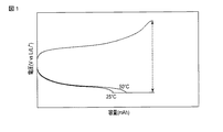
単斜晶系β型チタン複合酸化物は、充電末期においてリチウムイオン吸蔵量が一定量を越えるとリチウムイオンの吸蔵速度(拡散速度)が急減に低下して分極が大きくなり、電池の内部抵抗が増大する。一方で、リチウムイオンの拡散速度は温度に大きく依存する。よって、充電末期においてリチウムイオンの拡散速度が低下する程度は、温度に大きく依存する。 Monoclinic β-type titanium composite oxides have a lithium ion storage rate (diffusion rate) that decreases sharply when the lithium ion storage amount exceeds a certain level at the end of charging, and the polarization increases and the internal resistance of the battery decreases. Increase. On the other hand, the diffusion rate of lithium ions greatly depends on the temperature. Therefore, the degree to which the diffusion rate of lithium ions decreases at the end of charging greatly depends on the temperature.
図8に、25℃及び50℃のそれぞれについての正極及び負極の充電曲線を示した。温度が低い場合、充電末期においてリチウムイオンの拡散速度が低下するため内部抵抗が増大し、負極の電位が低下する。一方、温度が高い場合、リチウムイオンの拡散速度の低下の程度が小さく、内部抵抗が増大しないため、負極の電位があまり低下しない。そのため、図8に示すように、満充電状態の負極電位は、高温環境に晒されるほど高くなる。その結果、温度が高い程、正極電位も高くなる。 FIG. 8 shows charge curves of the positive electrode and the negative electrode for 25 ° C. and 50 ° C., respectively. When the temperature is low, the diffusion rate of lithium ions decreases at the end of charging, so that the internal resistance increases and the potential of the negative electrode decreases. On the other hand, when the temperature is high, the degree of decrease in the diffusion rate of lithium ions is small and the internal resistance does not increase, so the potential of the negative electrode does not decrease so much. Therefore, as shown in FIG. 8, the fully charged negative electrode potential becomes higher as it is exposed to a high temperature environment. As a result, the higher the temperature, the higher the positive electrode potential.
正極材料は、高温で高電位に晒されるほど劣化が激しくなる。それ故、単斜晶系β型チタン複合酸化物を用いた電池は高温環境下での正極の劣化が大きく、その結果、サイクル特性が低下していた。これは特に、4V程度の高いLi吸蔵電位を有する、LiCoO2のような層状構造の正極材料を用いた電池では顕著であった。 As the positive electrode material is exposed to a high potential at a high temperature, the deterioration becomes severe. Therefore, the battery using the monoclinic β-type titanium composite oxide is greatly deteriorated in the positive electrode under a high temperature environment, and as a result, the cycle characteristics are deteriorated. This was particularly remarkable in a battery using a positive electrode material having a layered structure such as LiCoO 2 having a high Li storage potential of about 4V.
そこで、本実施形態では、負極活物質として、単斜晶系β型チタン複合酸化物を含む第1の負極活物質と共に、Li吸蔵電位が単斜晶系β型チタン複合酸化物のLi吸蔵電位よりも卑である第2の負極活物質を用いる。このような負極では、充電時に正極活物質から放出されたリチウムイオンはまず、第1の負極活物質に吸蔵され、続いて第2の負極活物質に吸蔵される。放電時には、まず第2の負極活物質からリチウムイオンが放出され、続いて第1の負極活物質から放出される。 Therefore, in the present embodiment, the Li occlusion potential of the monoclinic β-type titanium composite oxide is Li together with the first negative electrode active material containing the monoclinic β-type titanium composite oxide as the negative electrode active material. The second negative electrode active material, which is more base, is used. In such a negative electrode, lithium ions released from the positive electrode active material during charging are first occluded in the first negative electrode active material and subsequently occluded in the second negative electrode active material. At the time of discharging, lithium ions are first released from the second negative electrode active material, and then released from the first negative electrode active material.
図1に、第1の負極活物質及び第2の負極活物質を含む負極を用いた電池の充電曲線を示した。充電開始後、第1の負極活物質にリチウムイオンが吸蔵され、電位が徐々に低下する。しかし、リチウムイオン吸蔵量が一定量を越えると、リチウムイオンは第2の負極活物質に吸蔵され、負極の電位が一定に保たれる。このような電池では、負極の満充電電位が第2の負極活物質の満充電電位で固定されるため、温度に影響されず一定になる。従って、高温環境下においても正極の電位が上昇しないため、正極の劣化を防ぐことができる。その結果、サイクル特性を向上させることができる。 FIG. 1 shows a charging curve of a battery using a negative electrode including a first negative electrode active material and a second negative electrode active material. After the start of charging, lithium ions are occluded in the first negative electrode active material, and the potential gradually decreases. However, if the amount of occlusion of lithium ions exceeds a certain amount, lithium ions are occluded in the second negative electrode active material, and the potential of the negative electrode is kept constant. In such a battery, since the full charge potential of the negative electrode is fixed at the full charge potential of the second negative electrode active material, it is constant regardless of the temperature. Therefore, since the potential of the positive electrode does not increase even in a high temperature environment, the positive electrode can be prevented from deteriorating. As a result, cycle characteristics can be improved.
第2の負極活物質としては、0.8V以上1.5V以下(vs. Li/Li+)の範囲でLiを吸蔵・放出する金属酸化物が用いられる。第2の負極活物質は、電位の温度依存性が小さく、また、充電曲線が平坦であるものが好ましい。第2の負極活物質のLi吸蔵電位が0.8V(vs. Li/Li+)より卑であると、単斜晶系β型チタン複合酸化物の充放電可逆性が低下し、負極の充放電可逆性が低下する虞がある。また、第2の負極活物質のLi吸蔵電位が1.5V(vs. Li/Li+)より貴であると、単斜晶系β型チタン複合酸化物の容量を十分に活用することができず、負極の電気容量が低下する虞がある。 As the second negative electrode active material, a metal oxide that absorbs and releases Li in the range of 0.8 V to 1.5 V (vs. Li / Li + ) is used. The second negative electrode active material preferably has a small temperature dependence of potential and a flat charging curve. If the Li storage potential of the second negative electrode active material is lower than 0.8 V (vs. Li / Li + ), the charge / discharge reversibility of the monoclinic β-type titanium composite oxide is reduced, and the charge / discharge of the negative electrode is reduced. There is a possibility that the reversibility of the discharge is lowered. In addition, if the Li storage potential of the second negative electrode active material is nobler than 1.5 V (vs. Li / Li + ), the capacity of the monoclinic β-type titanium composite oxide can be fully utilized. Therefore, the electric capacity of the negative electrode may be reduced.
第2の負極活物質として、Fe、Co、Ni、Cu及びMoからなる群から選択される少なくとも1種の元素を含む遷移金属含有酸化物を用いることができる。 As the second negative electrode active material, a transition metal-containing oxide containing at least one element selected from the group consisting of Fe, Co, Ni, Cu, and Mo can be used.
さらに、1.0〜1.5V(vs. Li/Li+)のLi吸蔵電位を有するモリブデン酸化物がより好ましく用いられる。 Furthermore, molybdenum oxide having a Li occlusion potential of 1.0 to 1.5 V (vs. Li / Li + ) is more preferably used.
また、第2の負極活物質として、空間群Cmcaに属する結晶構造を有するチタン含有酸化物を用いることができる。このようなチタン含有酸化物は、1.2V〜1.5V(vs. Li/Li+)のLi吸蔵電位を有する。 As the second negative electrode active material, a titanium-containing oxide having a crystal structure belonging to the space group Cmca can be used. Such a titanium-containing oxide has a Li storage potential of 1.2 V to 1.5 V (vs. Li / Li + ).
さらに、第2の負極活物質として、LixMoOy(0≦x≦2、1.9≦y≦2.1)で表される酸化物、及び、空間群Cmcaに属する結晶構造を有し、Li2+xAyTi6O14(ここで、AはNa、K、Mg、Ca、Ba及びSrよりなる群から選択される少なくとも1種の元素であり、0≦x≦5、1≦y≦2である)で表される酸化物から選択される遷移金属含有酸化物を用いることが好ましい。これらの遷移金属含有酸化物は、作用電位と充放電可逆性の観点から好適に用いることができる。 Further, the second negative electrode active material has an oxide represented by LixMoOy (0 ≦ x ≦ 2, 1.9 ≦ y ≦ 2.1) and a crystal structure belonging to the space group Cmca, and Li 2 + x A y Ti 6 O 14 (where A is at least one element selected from the group consisting of Na, K, Mg, Ca, Ba and Sr, and 0 ≦ x ≦ 5 and 1 ≦ y ≦ 2) It is preferable to use a transition metal-containing oxide selected from oxides represented by: These transition metal-containing oxides can be suitably used from the viewpoints of action potential and charge / discharge reversibility.
LixMoOy(0≦x≦2、1.9≦y≦2.1)で表される酸化物は、その結晶構造が空間群(P21/C)であることが好ましい。この物質はMoのMo4+⇔Mo3+の1電子反応で充放電が進行し、その理論容量は210mAh/gである。1電子反応(0≦x≦1)において、x=0.5を境に2つの充放電平坦部を示し、その電位は約1.3V(vs. Li/Li+)と約1.6V(vs. Li/Li+)である。この様な場合も、0.5≦x≦1で約1.3V(vs. Li/Li+)の電位でLiを吸蔵・放出するため、第2の負極活物質として機能させることが可能となる。なお、MoO2の対極Li金属の充放電曲線については、例えば、「電池ハンドブック(第1版)」(平成22年、株式会社オーム社 発行)p.417-418を参考にされたい。
The oxide represented by LixMoOy (0 ≦ x ≦ 2, 1.9 ≦ y ≦ 2.1) preferably has a crystal structure of the space group (P2 1 / C). This material is charged and discharged by a one-electron reaction of Mo 4 + ⇔Mo 3+ of Mo, and its theoretical capacity is 210 mAh / g. In a one-electron reaction (0 ≦ x ≦ 1), two charge / discharge flat portions are shown with x = 0.5 as a boundary, and the potential is about 1.3 V (vs. Li / Li + ) and about 1.6 V ( vs. Li / Li + ). Even in such a case, Li is occluded / released at a potential of about 1.3 V (vs. Li / Li + ) with 0.5 ≦ x ≦ 1, so that it can function as a second negative electrode active material. Doo ing. For the charge / discharge curve of MoO 2 counter electrode Li metal, refer to, for example, “Battery Handbook (First Edition)” (2010, published by Ohm Co., Ltd.) p.417-418.
すなわち、本願の第2の負極活物質は、0.8V以上1.5V以下(vs. Li/Li+)の範囲で一定量のLiを吸蔵・放出することが重要である。本願では0.8V以上1.5V以下(vs. Li/Li+)の範囲で吸蔵・放出するLi量が20mAh/g以上、好ましくは50mAh/g以上であることが好ましい。 That is, it is important for the second negative electrode active material of the present application to occlude and release a certain amount of Li in the range of 0.8 V to 1.5 V (vs. Li / Li + ). In the present application, the amount of Li occluded / released in the range of 0.8 V to 1.5 V (vs. Li / Li + ) is 20 mAh / g or more, preferably 50 mAh / g or more.
第1の負極活物質と第2の負極活物質の混合比は、負極単位面積当たりの質量比(A/B)が1以上100以下であることが好ましい。ここで、Aは第1の負極活物質の負極単位面積当たりの質量であり、Bは第2の負極活物質の負極単位面積当たりの質量である。質量比(A/B)が1以上であることにより、負極容量や充放電可逆性の低下を防ぐことができる。質量比(A/B)が100以下であることにより、充電末期の負極電位の安定性を得ることができる。質量比(A/B)は、1以上20以下の範囲であることがより好ましい。 As for the mixing ratio of the first negative electrode active material and the second negative electrode active material, the mass ratio (A / B) per unit area of the negative electrode is preferably 1 or more and 100 or less. Here, A is the mass per negative electrode unit area of the first negative electrode active material, and B is the mass per negative electrode unit area of the second negative electrode active material. When the mass ratio (A / B) is 1 or more, it is possible to prevent a decrease in negative electrode capacity and charge / discharge reversibility. When the mass ratio (A / B) is 100 or less, the stability of the negative electrode potential at the end of charging can be obtained. The mass ratio (A / B) is more preferably in the range of 1 or more and 20 or less.
負極に含まれる第1の負極活物質と第2の負極活物質の質量比(A/B)は、X線回折法により測定することができる。電極から剥ぎ取った負極活物質を測定ジグに設置し、X線回折装置(例えば、マックサイエンス社 型番M 1 8 X H F 2 2 - S R A) を用いて、C u - Kα を用いたX 線回折パターンを得、例えば、解析用ソフトウエア「RIETAN(商品名)」を用いて解析する。
The mass ratio (A / B) of the first negative electrode active material and the second negative electrode active material contained in the negative electrode can be measured by an X-ray diffraction method. The negative electrode active material stripped from the electrode is placed in a measurement jig, and an X-ray diffraction pattern using Cu-Kα using an X-ray diffractometer (for example, Mac Science Co., Ltd.,
さらに、本実施形態における非水電解質電池は、単位面積当たりの負極容量が正極容量よりも大きいことが好ましい。負極容量が正極容量より大きいことにより、寿命性能を更に高めることができる。より好ましい容量比は負極容量/正極容量が1.01以上である。 Furthermore, the nonaqueous electrolyte battery in the present embodiment preferably has a negative electrode capacity per unit area larger than a positive electrode capacity. When the negative electrode capacity is larger than the positive electrode capacity, the life performance can be further improved. A more preferable capacity ratio is negative electrode capacity / positive electrode capacity of 1.01 or more.
以下に、本実施形態の非水電解質二次電池について図面を参照しながら説明する。なお、実施の形態を通して共通の構成には同一の符号を付すものとし、重複する説明は省略する。また、各図は実施形態の説明とその理解を促すための模式図であり、その形状や寸法、比などは実際の装置と異なる個所があるが、これらは以下の説明と公知の技術を参酌して適宜、設計変更することができる。 Hereinafter, the nonaqueous electrolyte secondary battery of the present embodiment will be described with reference to the drawings. In addition, the same code | symbol shall be attached | subjected to a common structure through embodiment, and the overlapping description is abbreviate | omitted. Each figure is a schematic diagram for encouraging explanation of the embodiment and understanding thereof, and its shape, dimensions, ratio, and the like are different from those of the actual apparatus. However, these are considered in the following explanation and known technology. The design can be changed as appropriate.
図2に、本実施形態に係る非水電解質電池の一例を示す。図2は、扁平型非水電解質二次電池の断面模式図である。図3は、図2のA部の拡大断面図である。電池1は、外装部材2、偏平形状の捲回電極群3、正極端子7、負極端子8、及び非水電解質を備える。
FIG. 2 shows an example of the nonaqueous electrolyte battery according to this embodiment. FIG. 2 is a schematic cross-sectional view of a flat type nonaqueous electrolyte secondary battery. FIG. 3 is an enlarged cross-sectional view of a portion A in FIG. The
外装部材2はラミネートフィルムからなる袋状外装部材である。捲回電極群3は、外装部材2に収納されている。捲回電極群3は、図3に示すように、正極4、負極5、及びセパレータ6を含み、外側から負極5、セパレータ6、正極4、セパレータ6の順で積層した積層物を渦巻状に捲回し、プレス成型することにより形成される。
The
正極4は、正極集電体4aと正極層4bとを含む。正極層4bには正極活物質が含まれる。正極層4bは正極集電体4aの両面に形成されている。
The
負極5は、負極集電体5aと負極層5bとを含む。負極層5bには負極活物質が含まれる。負極5は、最外層においては、負極集電体5aの内面側の片面にのみ負極層5bが形成され、その他の部分では負極集電体5aの両面に負極層5bが形成されている。
The
図2に示すように、捲回電極群3の外周端近傍において、帯状の正極端子7が正極4の正極集電体4aに接続されている。また、帯状の負極端子8が最外層の負極5の負極集電体5aに接続されている。正極端子7及び負極端子8は、外装部材2の開口部を通って外部に延出されている。外装部材2の内部には、さらに、非水電解液が注入される。外装部材2の開口部を、正極端子7及び負極端子8を挟んだ状態でヒートシールすることにより、捲回電極群3及び非水電解質が完全密封される。
As shown in FIG. 2, a strip-like
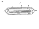
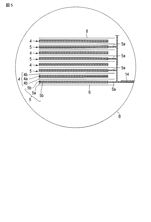
図4及び図5に、本実施形態に係る非水電解質電池の他の例を示す。図4は、他の形態の扁平型非水電解質二次電池の部分切欠斜視図である。図5は図4のB部の拡大図である。電池10は、積層型電極群11、外装部材12、正極端子13、負極端子14、及び非水電解質を備える。
4 and 5 show another example of the nonaqueous electrolyte battery according to the present embodiment. FIG. 4 is a partially cutaway perspective view of a flat type nonaqueous electrolyte secondary battery according to another embodiment. FIG. 5 is an enlarged view of a portion B in FIG. The
積層型電極群11は、ラミネートフィルムからなる外装部材12に収納されている。積層型電極群11は、図5に示すように、正極4と負極5が間にセパレータ6を挟んで交互に積層されて積層体を形成している。
The
正極4は複数枚存在し、それぞれが正極集電体4aと、正極集電体4aの両面に形成された正極活物質層4bとを備える。負極5は複数枚存在し、それぞれが負極集電体5aと、負極集電体5aの両面に形成された負極活物質層5bとを備える。
A plurality of
それぞれの負極5の負極集電体5aは、一辺が積層体から突出しており、帯状の負極端子14に接続されている。同様に、図示しないが、正極4の正極集電体4aは、負極集電体5aの突出した一辺と反対側に位置する一辺が積層体から突出しており、帯状の正極端子13に接続されている。
The negative electrode
負極端子14の先端は、外装部材12から外部に引き出されている。正極端子13の先端は、負極端子14とは反対側に位置し、外装部材12から外部に引き出されている。
The tip of the
外装部材12の内部には、さらに、非水電解液が注入される。
A non-aqueous electrolyte is further injected into the
(正極)
上記の実施形態の非水電解質電池に用いられる正極について説明する。
(Positive electrode)
The positive electrode used for the nonaqueous electrolyte battery of the above embodiment will be described.
正極は、正極集電体及び正極活物質層を含む。正極活物質層は、正極活物質、導電剤及び結着剤を含む。正極活物質層は、正極集電体の片面若しくは両面に形成される。 The positive electrode includes a positive electrode current collector and a positive electrode active material layer. The positive electrode active material layer includes a positive electrode active material, a conductive agent, and a binder. The positive electrode active material layer is formed on one side or both sides of the positive electrode current collector.
正極活物質として、種々の酸化物、硫化物及びポリマーを使用することができる。 Various oxides, sulfides and polymers can be used as the positive electrode active material.
酸化物の例には、Liを吸蔵した二酸化マンガン(MnO2)、酸化鉄、酸化銅、酸化ニッケル、及び、リチウムマンガン複合酸化物(例えばLixMn2O4又はLixMnO2)、リチウムニッケル複合酸化物(例えばLixNiO2)、リチウムコバルト複合酸化物(LixCoO2)、リチウムニッケルコバルト複合酸化物(例えばLiNi1-yCoyO2)、リチウムマンガンコバルト複合酸化物(例えばLiMnyCo1-yO2)、スピネル型リチウムマンガンニッケル複合酸化物(LixMn2-yNiyO4)、オリビン構造を有するリチウムリン酸化物(LixFePO4、LixFe1-yMnyPO4、LixCoPO4等)、硫酸鉄(Fe2(SO4)3)、バナジウム酸化物(例えばV2O5)、及び、リチウムニッケルコバルトマンガン複合酸化物が含まれる。なお、上式におけるx及びyは0〜1の範囲であることが好ましい。 Examples of oxides include Li-occluded manganese dioxide (MnO 2 ), iron oxide, copper oxide, nickel oxide, and lithium manganese composite oxide (for example, Li x Mn 2 O 4 or Li x MnO 2 ), lithium Nickel composite oxide (for example, Li x NiO 2 ), lithium cobalt composite oxide (Li x CoO 2 ), lithium nickel cobalt composite oxide (for example, LiNi 1-y Co y O 2 ), lithium manganese cobalt composite oxide (for example, LiMn y Co 1-y O 2 ), spinel-type lithium manganese nickel composite oxide (Li x Mn 2-y Ni y O 4 ), lithium phosphorus oxide having an olivine structure (Li x FePO 4 , Li x Fe 1- y Mn y PO 4 , Li x CoPO 4, etc.), iron sulfate (Fe 2 (SO 4 ) 3 ), vanadium oxide (for example, V 2 O 5 ), and lithium nickel cobalt manganese composite oxide. In addition, it is preferable that x and y in the above formula are in the range of 0-1.
高い正極電圧が得られる酸化物の例には、リチウムマンガン複合酸化物(LixMn2O4)、リチウムニッケル複合酸化物(LixNiO2)、リチウムコバルト複合酸化物(LixCoO2)、リチウムニッケルコバルト複合酸化物(LixNi1-yCoyO2)、スピネル構造を有するリチウムマンガンニッケル複合酸化物(LixMn2-yNiyO4)、リチウムマンガンコバルト複合酸化物(LixMnyCo1-yO2)、リチウムリン酸鉄(LixFePO4)、及び、リチウムニッケルコバルトマンガン複合酸化物が含まれる。なお、上式におけるx及びyは0〜1の範囲であることが好ましい。 Examples of oxides that can provide high positive voltage include lithium manganese composite oxide (Li x Mn 2 O 4 ), lithium nickel composite oxide (Li x NiO 2 ), lithium cobalt composite oxide (Li x CoO 2 ) , Lithium nickel cobalt composite oxide (Li x Ni 1-y Co y O 2 ), lithium manganese nickel composite oxide with spinel structure (Li x Mn 2-y Ni y O 4 ), lithium manganese cobalt composite oxide ( Li x Mn y Co 1-y O 2), lithium iron phosphate (Li x FePO 4), and includes a lithium-nickel-cobalt-manganese composite oxide. In addition, it is preferable that x and y in the above formula are in the range of 0-1.
サイクル特性の観点から、ニッケルを含有するリチウム複合酸化物を用いることが好ましい。中でも、組成式LiaNibCocMndO2(0≦a≦1.1、0.1≦b≦0.5、0≦c≦0.9、0.1≦d≦0.5)で表されるようなリチウムニッケルコバルトマンガン複合酸化物は熱安定性が高いために好ましい。 From the viewpoint of cycle characteristics, it is preferable to use a lithium composite oxide containing nickel. Among them, a lithium nickel cobalt manganese composite represented by the composition formula Li a Ni b Co c Mn d O 2 (0 ≦ a ≦ 1.1, 0.1 ≦ b ≦ 0.5, 0 ≦ c ≦ 0.9, 0.1 ≦ d ≦ 0.5) Oxides are preferred because of their high thermal stability.
層状構造を有する酸化物は、過充電時に層状構造が壊れやすく、劣化しやすい。また、リチウム及びニッケルを含有する酸化物は過充電時に劣化しやすい。よって、正極活物質としてそれらの酸化物を用いた場合、本実施形態の効果が得られやすい。 An oxide having a layered structure easily breaks down and deteriorates during overcharge. In addition, an oxide containing lithium and nickel is likely to deteriorate during overcharge. Therefore, when those oxides are used as the positive electrode active material, the effect of this embodiment is easily obtained.
正極活物質として、スピネル構造を有するリチウムマンガンニッケル複合酸化物を用いることにより、電池の高電圧化も可能である。あるいは、正極活物質にオリビン構造を有するリチウムリン複合酸化物(例えば、LixFePO4、LixFe1-xMnyPO4、LixVPO4F、LixCoPO4など、0≦x≦1、0≦y≦1)を含めることによって、熱安定性に優れた非水電解質電池を実現することができる。
By using a lithium manganese nickel composite oxide having a spinel structure as the positive electrode active material, the battery voltage can be increased. Alternatively, lithium phosphorus complex oxide having an olivine structure as the positive electrode active material (e.g., Li x FePO 4, Li x Fe 1-x
中でも、常温溶融塩を含む非水電解質を用いる際には、リチウムリン酸鉄、LixVPO4F、リチウムマンガン複合酸化物、リチウムニッケル複合酸化物、リチウムニッケルコバルト複合酸化物を用いることが、サイクル寿命の観点から好ましい。これは、上記正極活物質と常温溶融塩との反応性が少なくなるためである。 Among them, when using a non-aqueous electrolyte containing a room temperature molten salt, it is possible to use lithium iron phosphate, Li x VPO 4 F, lithium manganese composite oxide, lithium nickel composite oxide, lithium nickel cobalt composite oxide, It is preferable from the viewpoint of cycle life. This is because the reactivity between the positive electrode active material and the room temperature molten salt is reduced.
また、正極活物質として、式(II)で表されるリチウム金属酸化物を用いることができる。 Moreover, the lithium metal oxide represented by Formula (II) can be used as a positive electrode active material.
xLi2MeO3 - (1-x)LiMe'O2 (II)
式中、0<x<1であり、Me及びMe'はそれぞれ独立的に、Mn、Ti、Zr、V、Cr、Fe、Co、Ni、Cu、Al、Mg、Zr、B及びMoからなる群から選択される少なくとも1種の元素である。
式(II)で表されるリチウム金属酸化物は、作用電位が高く、過充電状態に晒されると電解液との反応が進み、顕著に劣化する。よって、このような正極活物質を用いた場合、本実施形態の効果が得られやすい。
xLi 2 MeO 3- (1-x) LiMe'O 2 (II)
In the formula, 0 <x <1, and Me and Me ′ are independently composed of Mn, Ti, Zr, V, Cr, Fe, Co, Ni, Cu, Al, Mg, Zr, B, and Mo. At least one element selected from the group.
The lithium metal oxide represented by the formula (II) has a high action potential, and when exposed to an overcharged state, the reaction with the electrolyte proceeds and the lithium metal oxide is significantly deteriorated. Therefore, when such a positive electrode active material is used, the effect of this embodiment is easily obtained.
また、ポリアニリン及びポリピロールのような導電性ポリマー材料、ジスルフィド系ポリマー材料、イオウ(S)、フッ化カーボンのような有機材料及び無機材料を正極活物質として用いることもできる。 In addition, conductive polymer materials such as polyaniline and polypyrrole, disulfide-based polymer materials, organic materials such as sulfur (S) and carbon fluoride, and inorganic materials can also be used as the positive electrode active material.
正極活物質は、上記の化合物を単独で又は組合せて用いることができる。 As the positive electrode active material, the above compounds can be used alone or in combination.
正極活物質の1次粒子径は、100nm以上1μm以下であることが好ましい。100nm以上であると、工業生産上扱いやすい。1μm以下であると、リチウムイオンの固体内拡散をスムーズに進行させることができる。 The primary particle diameter of the positive electrode active material is preferably 100 nm or more and 1 μm or less. It is easy to handle in industrial production as it is 100 nm or more. When the thickness is 1 μm or less, diffusion of lithium ions in the solid can proceed smoothly.
正極活物質の比表面積は、0.1m2/g以上10m2/g以下であることが好ましい。0.1m2/g以上であると、リチウムイオンの吸蔵・放出サイトを十分に確保できる。10m2/g以下であると、工業生産上扱いやすく、良好な充放電サイクル性能を確保できる。 The specific surface area of the positive electrode active material is preferably 0.1 m 2 / g or more and 10 m 2 / g or less. When it is 0.1 m 2 / g or more, sufficient lithium ion storage / release sites can be secured. When it is 10 m 2 / g or less, it is easy to handle in industrial production, and good charge / discharge cycle performance can be secured.
導電剤は、集電性能を高め、集電体との接触抵抗を抑えるために用いられる。導電剤の例には、アセチレンブラック、カーボンブラック及び黒鉛のような炭素質物が含まれる。 The conductive agent is used to improve current collection performance and suppress contact resistance with the current collector. Examples of the conductive agent include carbonaceous materials such as acetylene black, carbon black, and graphite.
結着剤は、活物質と導電剤を結着させるために用いられる。結着剤の例には、ポリテトラフルオロエチレン(PTFE)、ポリフッ化ビニリデン(PVdF)、及びフッ素系ゴムが含まれる。 The binder is used to bind the active material and the conductive agent. Examples of the binder include polytetrafluoroethylene (PTFE), polyvinylidene fluoride (PVdF), and fluorine-based rubber.
正極活物質、正極導電剤及び結着剤の配合比は、正極活物質が80質量%以上95質量%以下、正極導電剤が3質量%以上18質量%以下、結着剤が2質量%以上17質量%以下の範囲であることが好ましい。正極導電剤については、3質量%以上であることにより上述した効果を発揮することができ、18質量%以下であることにより、高温保存下での正極導電剤表面での非水電解質の分解を低減することができる。結着剤については、2質量%以上であることにより十分な電極強度が得られ、17質量%以下であることにより、電極の絶縁体の配合量を減少させ、内部抵抗を減少できる。 The compounding ratio of the positive electrode active material, the positive electrode conductive agent and the binder is such that the positive electrode active material is 80% by mass to 95% by mass, the positive electrode conductive agent is 3% by mass to 18% by mass, and the binder is 2% by mass or more. It is preferable that it is the range of 17 mass% or less. With respect to the positive electrode conductive agent, the effect described above can be exhibited by being 3% by mass or more, and by being 18% by mass or less, decomposition of the nonaqueous electrolyte on the surface of the positive electrode conductive agent under high temperature storage can be achieved. Can be reduced. When the amount of the binder is 2% by mass or more, sufficient electrode strength can be obtained, and when the amount is 17% by mass or less, the amount of the insulator in the electrode can be reduced and the internal resistance can be reduced.
正極集電体は、アルミニウム箔若しくはアルミニウム合金箔であることが好ましい。その平均結晶粒径は50μm以下であることが好ましく、30μm以下であることがより好ましく、5μm以下であることがさらに好ましい。平均結晶粒径が50μm以下であることにより、アルミニウム箔又はアルミニウム合金箔の強度を飛躍的に増大させることができ、正極を高いプレス圧で高密度化することが可能になり、電池容量を増大させることができる。 The positive electrode current collector is preferably an aluminum foil or an aluminum alloy foil. The average crystal grain size is preferably 50 μm or less, more preferably 30 μm or less, and even more preferably 5 μm or less. When the average crystal grain size is 50 μm or less, the strength of the aluminum foil or aluminum alloy foil can be drastically increased, the positive electrode can be densified with a high press pressure, and the battery capacity is increased. Can be made.
アルミニウム箔又はアルミニウム合金箔の平均結晶粒径は、材料組織、不純物、加工条件、熱処理履歴、ならびに焼鈍条件など複数の因子に複雑に影響される。平均結晶粒径は、製造工程中で上記の諸因子を組合せることにより、50μm以下の範囲に調整される。 The average crystal grain size of the aluminum foil or aluminum alloy foil is complicatedly influenced by a plurality of factors such as material structure, impurities, processing conditions, heat treatment history, and annealing conditions. The average crystal grain size is adjusted to a range of 50 μm or less by combining the above factors in the manufacturing process.
平均結晶粒径は次のようにして求められる。集電体表面の組織を光学顕微鏡で組織観察し、1mm×1mm内に損竿する結晶粒の数nを求める。このnを用いてS=1×10⁶/n(μm2)から平均結晶粒径面積Sを求める。得られたSの値から式(III)により、平均結晶粒径d(μm)を算出する。 The average crystal grain size is determined as follows. The structure of the current collector surface is observed with an optical microscope, and the number n of crystal grains damaged within 1 mm × 1 mm is determined. Using this n, the average crystal grain size area S is determined from S = 1 × 10 6 / n (μm 2 ). The average crystal grain size d (μm) is calculated from the obtained S value by the formula (III).
d=2(S/π)1/2 (III)
アルミニウム箔及びアルミニウム合金箔の厚さは、20μm以下であることが好ましく、15μm以下であることがより好ましい。アルミニウム箔の純度は99質量%以上であることが好ましい。アルミニウム合金としては、マグネシウム、亜鉛、ケイ素、などの元素を含む合金が好ましい。一方、鉄、銅、ニッケル、クロムなどの遷移金属の含有量は1質量%以下であることが好ましい。
d = 2 (S / π) 1/2 (III)
The thickness of the aluminum foil and the aluminum alloy foil is preferably 20 μm or less, and more preferably 15 μm or less. The purity of the aluminum foil is preferably 99% by mass or more. As the aluminum alloy, an alloy containing elements such as magnesium, zinc and silicon is preferable. On the other hand, the content of transition metals such as iron, copper, nickel, and chromium is preferably 1% by mass or less.
正極は、例えば次の方法により作製することができる。まず、正極活物質、導電剤及び結着剤を溶媒に懸濁してスラリーを調製する。このスラリーを、正極集電体の片面又は両面に塗布し、乾燥して、正極活物質層を形成する。その後、プレスを施す。或いは、正極活物質、導電剤及び結着剤をペレット状に形成し、正極活物質層として用いることもできる。 The positive electrode can be produced, for example, by the following method. First, a positive electrode active material, a conductive agent, and a binder are suspended in a solvent to prepare a slurry. This slurry is applied to one or both sides of the positive electrode current collector and dried to form a positive electrode active material layer. Then press. Alternatively, the positive electrode active material, the conductive agent, and the binder can be formed in a pellet shape and used as the positive electrode active material layer.
(負極)
上記の実施形態の非水電解質電池に用いられる負極について説明する。
(Negative electrode)
The negative electrode used for the nonaqueous electrolyte battery of the above embodiment will be described.
負極は、負極集電体及び負極活物質層を含む。負極活物質層は、第1の負極活物質、第2の負極活物質、導電剤及び結着剤を含む。負極活物質層は、負極集電体の片面若しくは両面に形成される。 The negative electrode includes a negative electrode current collector and a negative electrode active material layer. The negative electrode active material layer includes a first negative electrode active material, a second negative electrode active material, a conductive agent, and a binder. The negative electrode active material layer is formed on one side or both sides of the negative electrode current collector.
負極中で、第1の負極活物質と第2の負極活物質は混合物の状態で存在する。第1の負極活物質と第2の負極活物質の状態は、粉末X線回折測定によるピークによって確認することができる。第1の負極活物質と第2の負極活物質が混合された状態にある場合、第1の負極活物質に由来するピークと、第2の負極活物質に由来するピークの2つのピークが検出できる。 In the negative electrode, the first negative electrode active material and the second negative electrode active material exist in a mixture state. The state of the first negative electrode active material and the second negative electrode active material can be confirmed by a peak by powder X-ray diffraction measurement. When the first negative electrode active material and the second negative electrode active material are mixed, two peaks, a peak derived from the first negative electrode active material and a peak derived from the second negative electrode active material, are detected. it can.
第1の負極活物質には、単斜晶系β型チタン複合酸化物が含まれる。単斜晶系β型チタン複合酸化物を用いることにより、高い負極容量を得ることができる。 The first negative electrode active material includes monoclinic β-type titanium composite oxide. A high negative electrode capacity can be obtained by using the monoclinic β-type titanium composite oxide.
第2の負極活物質には、0.8V以上1.5V以下(vs Li/Li+)の範囲でLiを吸蔵・放出する物質が用いられる。その例には、Fe、Co、Ni、Cu及びMoからなる群から選択される少なくとも1種の元素を含む遷移金属含有酸化物、及び、空間群Cmcaに属する結晶構造を有するチタン含有酸化物が含まれる。特にモリブデン酸化物が好適に用いられる。これらの酸化物は、サイクル特性が良く、容量劣化が少ないため好ましい。 As the second negative electrode active material, a material that absorbs and releases Li in the range of 0.8 V to 1.5 V (vs Li / Li + ) is used. Examples thereof include a transition metal-containing oxide containing at least one element selected from the group consisting of Fe, Co, Ni, Cu and Mo, and a titanium-containing oxide having a crystal structure belonging to the space group Cmca. included. In particular, molybdenum oxide is preferably used. These oxides are preferable because they have good cycle characteristics and little capacity deterioration.
第2の負極活物質の好ましい例には、LixMoOy(0≦x≦2、1.9≦y≦2.1)で表される酸化物、及び、空間群Cmcaに属する結晶構造を有し、Li2+xAyTi6O14(ここで、AはNa、K、Mg、Ca、Ba及びSrよりなる群から選択される少なくとも1種の元素であり、0≦x≦5、1≦y≦2である)で表される酸化物が含まれる。これらの酸化物は、作用電位と充放電可逆性の観点から好適に用いることができる。 Preferred examples of the second negative electrode active material include an oxide represented by LixMoOy (0 ≦ x ≦ 2, 1.9 ≦ y ≦ 2.1) and a crystal structure belonging to the space group Cmca, and Li 2 + x A y Ti 6 O 14 (where A is at least one element selected from the group consisting of Na, K, Mg, Ca, Ba and Sr, and 0 ≦ x ≦ 5, 1 ≦ y ≦ 2) Oxides represented by These oxides can be suitably used from the viewpoints of working potential and charge / discharge reversibility.
上記の第1の負極活物質及び第2の負極活物質は予めLiを含むものであってもよいが、電池を充電することによってLiを含有するものであってもよい。 The first negative electrode active material and the second negative electrode active material may contain Li in advance, but may contain Li by charging the battery.
負極は、第1の負極活物質と第2の負極活物質を、負極単位面積当たりの質量比(A/B)が1以上100以下である範囲で含むことが好ましく、1以上20以下の範囲で含むことがより好ましい。 The negative electrode preferably includes the first negative electrode active material and the second negative electrode active material in a range where the mass ratio (A / B) per unit area of the negative electrode is from 1 to 100, preferably from 1 to 20. It is more preferable to contain.
本実施形態における非水電解質電池は、第2の負極活物質として、モリブデン酸化物又はリチウムチタン複合酸化物を用い、正極活物質として、式(II)で表されるリチウム金属酸化物を用い、第1の負極活物質と第2の負極活物質の混合比(A/B)が1以上20以下である構成を有することが好ましい。 The nonaqueous electrolyte battery in the present embodiment uses molybdenum oxide or lithium titanium composite oxide as the second negative electrode active material, and uses a lithium metal oxide represented by the formula (II) as the positive electrode active material, It is preferable that the mixing ratio (A / B) of the first negative electrode active material and the second negative electrode active material is 1 or more and 20 or less.
単斜晶系β型チタン複合酸化物の平均粒径は、大き過ぎると大電流性能が低下するため、3μm以下であることが好ましい。単斜晶系β型チタン複合酸化物の平均粒径の下限は、特に限定されない。但し、電池性能の低下現象は、単斜晶系β型チタン複合酸化物の平均一次粒径(繊維状粒子の場合、平均繊維径)が0.03μm以上になるとより顕著に現れる。これは、単斜晶系β型チタン複合酸化物の粒径が大きくなることで、リチウムイオン拡散速度の温度依存性がより強く影響するためである。よって、その平均粒径は0.03μm以上とすることができる。 The average particle size of the monoclinic β-type titanium composite oxide is preferably 3 μm or less because large current performance is deteriorated if it is too large. The lower limit of the average particle diameter of the monoclinic β-type titanium composite oxide is not particularly limited. However, the battery performance deterioration phenomenon appears more prominently when the average primary particle size (average fiber diameter in the case of fibrous particles) of the monoclinic β-type titanium composite oxide is 0.03 μm or more. This is because the temperature dependence of the lithium ion diffusion rate is more strongly affected by the increase in the particle size of the monoclinic β-type titanium composite oxide. Therefore, the average particle diameter can be 0.03 μm or more.
また、単斜晶系β型チタン複合酸化物の比表面積は、N2吸着によるBET法で測定したとき5〜50m2/gの範囲であることが望ましい。比表面積が上記範囲であると、単斜晶系β型チタン複合酸化物の利用率を高めることができ、高率充放電においても実質的に高い容量を得ることができる。 The specific surface area of the monoclinic β-type titanium composite oxide is preferably in the range of 5 to 50 m 2 / g as measured by the BET method using N 2 adsorption. When the specific surface area is in the above range, the utilization rate of the monoclinic β-type titanium composite oxide can be increased, and a substantially high capacity can be obtained even in high rate charge / discharge.
負極の気孔率(集電体を除く)は、20〜50%の範囲にすることが望ましい。これにより、負極と非水電解質との親和性に優れ、かつ高密度な負極を得ることができる。気孔度の更に好ましい範囲は、25〜40%である。 The porosity of the negative electrode (excluding the current collector) is desirably in the range of 20 to 50%. Thereby, it is possible to obtain a negative electrode having excellent affinity between the negative electrode and the non-aqueous electrolyte and a high density. A more preferable range of the porosity is 25 to 40%.
負極集電体は、アルミニウム箔又はアルミニウム合金箔であることが好ましい。その平均結晶粒径は50μm以下であることが好ましく、30μm以下であることがより好ましく、5μm以下であることがさらに好ましい。これにより、集電体の強度を飛躍的に増大させることができるため、負極を高いプレス圧で高密度化することが可能となり、電池容量を増大させることができる。また、高温環境下(40℃以上)における過放電サイクルでの負極集電体の溶解・腐食劣化を防ぐことができるため、負極インピーダンスの上昇を抑制することができる。さらに、出力特性、急速充電、充放電サイクル特性も向上させることができる。平均結晶粒径の調整方法及びその測定方法は、上記正極の項で述べたとおりである。 The negative electrode current collector is preferably an aluminum foil or an aluminum alloy foil. The average crystal grain size is preferably 50 μm or less, more preferably 30 μm or less, and even more preferably 5 μm or less. Thereby, since the intensity | strength of an electrical power collector can be increased greatly, it becomes possible to make a negative electrode high density with a high press pressure, and can increase battery capacity. Moreover, since the dissolution / corrosion deterioration of the negative electrode current collector in the overdischarge cycle under a high temperature environment (40 ° C. or higher) can be prevented, an increase in the negative electrode impedance can be suppressed. Furthermore, output characteristics, quick charge, and charge / discharge cycle characteristics can also be improved. The method for adjusting the average crystal grain size and the measuring method thereof are as described in the section of the positive electrode.
アルミニウム箔及びアルミニウム合金箔の厚さは、20μm以下であることが好ましく、15μm以下であることがより好ましい。アルミニウム箔の純度は99質量%以上であることが好ましい。アルミニウム合金としては、マグネシウム、亜鉛、ケイ素、などの元素を含む合金が好ましい。一方、鉄、銅、ニッケル、クロムなどの遷移金属の含有量は1質量%以下であることが好ましい。 The thickness of the aluminum foil and the aluminum alloy foil is preferably 20 μm or less, and more preferably 15 μm or less. The purity of the aluminum foil is preferably 99% by mass or more. As the aluminum alloy, an alloy containing elements such as magnesium, zinc and silicon is preferable. On the other hand, the content of transition metals such as iron, copper, nickel, and chromium is preferably 1% by mass or less.
導電剤としては、例えば、炭素材料を用いることができる。炭素材料の例には、アセチレンブラック、カーボンブラック、コークス、炭素繊維及び黒鉛が含まれる。その他の例には、アルミニウム粉末などの金属粉末、TiOなどの導電性セラミックスが含まれる。熱処理温度が800〜2000℃の平均粒子径10μm以下のコークス、黒鉛、TiOの粉末、平均粒子径1μm以下の炭素繊維が好ましい。それらの炭素材料のN2吸着によるBET比表面積は10m2/g以上であることが好ましい。 As the conductive agent, for example, a carbon material can be used. Examples of the carbon material include acetylene black, carbon black, coke, carbon fiber, and graphite. Other examples include metal powders such as aluminum powder and conductive ceramics such as TiO. Coke, graphite, TiO powder having an average particle diameter of 10 μm or less at a heat treatment temperature of 800 to 2000 ° C., and carbon fiber having an average particle diameter of 1 μm or less are preferable. The BET specific surface area by N 2 adsorption their carbon material is preferably 10 m 2 / g or more.
結着剤の例には、ポリテトラフルオロエチレン(PTFE)、ポリフッ化ビニリデン(PVdF)、フッ素系ゴム、スチレンブタジエンゴム、及びコアシェルバインダーが含まれる。 Examples of the binder include polytetrafluoroethylene (PTFE), polyvinylidene fluoride (PVdF), fluorine-based rubber, styrene butadiene rubber, and core-shell binder.
負極活物質、負極導電剤及び結着剤の配合比は、負極活物質は70質量%以上96質量%以下、負極導電剤は2質量%以上28質量%以下、結着剤は2質量%以上28質量%以下の範囲であることが好ましい。負極導電剤量が2質量%未満であると、負極活物質層の集電性能が低下し、非水電解質二次電池の大電流特性が低下する恐れがある。また、結着剤量が2質量%未満であると、負極活物質層と負極集電体の結着性が低下し、サイクル特性が低下する恐れがある。一方、高容量化の観点から、負極導電剤及び結着剤は各々28質量%以下であることが好ましい。 The compounding ratio of the negative electrode active material, the negative electrode conductive agent and the binder is such that the negative electrode active material is 70% by mass to 96% by mass, the negative electrode conductive agent is 2% by mass to 28% by mass, and the binder is 2% by mass or more. The range is preferably 28% by mass or less. If the amount of the negative electrode conductive agent is less than 2% by mass, the current collecting performance of the negative electrode active material layer may be reduced, and the large current characteristics of the nonaqueous electrolyte secondary battery may be reduced. In addition, when the amount of the binder is less than 2% by mass, the binding property between the negative electrode active material layer and the negative electrode current collector is lowered, and the cycle characteristics may be lowered. On the other hand, from the viewpoint of increasing the capacity, the negative electrode conductive agent and the binder are each preferably 28% by mass or less.
負極は、例えば次の方法により作製することができる。まず、負極活物質、導電剤及び結着剤を溶媒に懸濁してスラリーを調製する。このスラリーを、負極集電体の片面又は両面に塗布し、乾燥して、負極活物質層を形成する。その後、プレスを施す。或いは、負極活物質、導電剤及び結着剤をペレット状に形成し、負極活物質層として用いることもできる。 The negative electrode can be produced, for example, by the following method. First, a negative electrode active material, a conductive agent, and a binder are suspended in a solvent to prepare a slurry. This slurry is applied to one or both sides of the negative electrode current collector and dried to form a negative electrode active material layer. Then press. Alternatively, the negative electrode active material, the conductive agent, and the binder can be formed in a pellet shape and used as the negative electrode active material layer.
(非水電解質)
上記の実施形態の非水電解質電池に用いられる非水電解質について説明する。
(Nonaqueous electrolyte)
The nonaqueous electrolyte used for the nonaqueous electrolyte battery of the above embodiment will be described.
非水電解質として、液状非水電解質、又はゲル状非水電解質を用いることができる。液状非水電解質は、電解質を有機溶媒に溶解することにより調製できる。ゲル状非水電解質は、液状電解質と高分子材料を複合化することにより調製できる。 As the non-aqueous electrolyte, a liquid non-aqueous electrolyte or a gel-like non-aqueous electrolyte can be used. The liquid non-aqueous electrolyte can be prepared by dissolving the electrolyte in an organic solvent. The gel-like nonaqueous electrolyte can be prepared by combining a liquid electrolyte and a polymer material.
非水電解質には、揮発性がなく、不燃性のイオン性液体からなる常温溶融塩を含有させることが好ましい。 The nonaqueous electrolyte preferably contains a room temperature molten salt made of a non-flammable ionic liquid that is not volatile.
液状非水電解質における電解質の濃度は、0.5mol/L以上2.5mol/L以下の範囲であることが好ましい。 The concentration of the electrolyte in the liquid non-aqueous electrolyte is preferably in the range of 0.5 mol / L to 2.5 mol / L.
電解質の例には、過塩素酸リチウム(LiClO4)、六フッ化リン酸リチウム(LiPF6)、四フッ化ホウ酸リチウム(LiBF4)、六フッ化砒素リチウム(LiAsF6)、トリフルオロメタスルホン酸リチウム(LiCF3SO3)、及び、ビストリフルオロメチルスルホニルイミトリチウム[LiN(CF3SO2)2]のようなリチウム塩が含まれる。これらの電解質は、単独で又は2種類以上を組合せて用いることができる。電解質は、高電位でも酸化し難いものであることが好ましく、LiPF6が最も好ましい。 Examples of electrolytes include lithium perchlorate (LiClO 4 ), lithium hexafluorophosphate (LiPF 6 ), lithium tetrafluoroborate (LiBF 4 ), lithium arsenic hexafluoride (LiAsF 6 ), trifluorometa Lithium salts such as lithium sulfonate (LiCF 3 SO 3 ) and bistrifluoromethylsulfonylimitolithium [LiN (CF 3 SO 2 ) 2 ] are included. These electrolytes can be used alone or in combination of two or more. The electrolyte is preferably one that is not easily oxidized even at a high potential, and LiPF 6 is most preferred.
有機溶媒の例には、プロピレンカーボネート(PC)、エチレンカーボネート(EC)、及びビニレンカーボネートのような環状カーボネート、ジエチルカーボネート(DEC)、ジメチルカーボネート(DMC)、及びメチルエチルカーボネート(MEC)のような鎖状カーボネート、テトラヒドロフラン(THF)、2メチルテトラヒドロフラン(2MeTHF)、及びジオキソラン(DOX)のような環状エーテル、ジメトキシエタン(DME)、及びジエトエタン(DEE)のような鎖状エーテル、γ-ブチロラクトン(GBL)、アセトニトリル(AN)、及びスルホラン(SL)が含まれる。 Examples of organic solvents include cyclic carbonates such as propylene carbonate (PC), ethylene carbonate (EC), and vinylene carbonate, such as diethyl carbonate (DEC), dimethyl carbonate (DMC), and methyl ethyl carbonate (MEC). Cyclic ethers such as linear carbonates, tetrahydrofuran (THF), 2-methyltetrahydrofuran (2MeTHF), and dioxolane (DOX), linear ethers such as dimethoxyethane (DME), and dietoethane (DEE), γ-butyrolactone (GBL) ), Acetonitrile (AN), and sulfolane (SL).
これらの有機溶媒は、単独で又は2種類以上を組合せて用いることができる。プロピレンカーボネート(PC)、エチレンカーボネート(EC)及びγ−ブチロラクトン(GBL)からなる群のうち、2種以上を混合した混合溶媒が好ましい。 These organic solvents can be used alone or in combination of two or more. Of the group consisting of propylene carbonate (PC), ethylene carbonate (EC) and γ-butyrolactone (GBL), a mixed solvent in which two or more kinds are mixed is preferable.
さらに好ましい有機溶媒として、γ−ブチロラクトン(GBL)が挙げられる。その理由は以下の通りである。 A more preferable organic solvent is γ-butyrolactone (GBL). The reason is as follows.
第一に、γ−ブチロラクトン、プロピレンカーボネート、エチレンカーボネートは沸点や引火点が高く、熱安定性に優れるためである。 First, γ-butyrolactone, propylene carbonate, and ethylene carbonate have high boiling points and flash points, and are excellent in thermal stability.
第二に、リチウムチタン複合酸化物は、1.5V(vs. Li/Li+)近傍の電位域でリチウムイオンを吸蔵及び放出する。しかしながら、この電位域では、非水電解質の還元分解が起こり難く、リチウムチタン複合酸化物表面に非水電解質の還元生成物である皮膜が形成され難い。このため、リチウム吸蔵状態、すなわち充電状態で保存すると、リチウムチタン複合酸化物に吸蔵されていたリチウムイオンが徐々に電解液中に拡散し、所謂自己放電が生じてしまう。自己放電は、電池の保管環境が高温になると顕著に表れる。 Secondly, the lithium titanium composite oxide occludes and releases lithium ions in a potential range near 1.5 V (vs. Li / Li + ). However, in this potential region, the reductive decomposition of the nonaqueous electrolyte hardly occurs, and a film that is a reduction product of the nonaqueous electrolyte is hardly formed on the surface of the lithium titanium composite oxide. For this reason, when stored in a lithium occlusion state, that is, in a charged state, lithium ions occluded in the lithium titanium composite oxide are gradually diffused into the electrolytic solution, and so-called self-discharge occurs. Self-discharge is prominent when the storage environment of the battery becomes high.
ここで、γ−ブチロラクトンは、鎖状カーボネートや環状カーボネートに比べて、還元されやすい。具体的には、γ−ブチロラクトン>>>エチレンカーボネート>プロピレンカーボネート>>ジメチルカーボネート>メチルエチルカーボネート>ジエチルカーボネートの順に還元されやすい。なお、>の数が多いほど、溶媒間の反応性に差があることを示している。 Here, γ-butyrolactone is more easily reduced than chain carbonates and cyclic carbonates. Specifically, it is easy to reduce in the order of γ-butyrolactone >> ethylene carbonate> propylene carbonate >> dimethyl carbonate> methyl ethyl carbonate> diethyl carbonate. In addition, it has shown that there exists a difference in the reactivity between solvents, so that there are many numbers of>.
そのため、γ−ブチロラクトンを電解液中に含有させると、リチウムチタン複合酸化物の作動電位域においても、リチウムチタン複合酸化物の表面に良好な皮膜が形成できる。この結果、自己放電を抑制し、非水電解質電池の高温貯蔵特性を向上できる。これは上述の混合溶媒についても同様である。 Therefore, when γ-butyrolactone is contained in the electrolytic solution, a good film can be formed on the surface of the lithium titanium composite oxide even in the operating potential range of the lithium titanium composite oxide. As a result, self-discharge can be suppressed and the high-temperature storage characteristics of the nonaqueous electrolyte battery can be improved. The same applies to the above mixed solvent.
また、還元され易い常温溶融塩を用いる場合も、γ―ブチロラクトンを含有することにより同様の効果が得られる。さらに、常温溶融塩の場合、酸化もされ易いため、正極に作用して、自己放電の抑制やサイクル寿命を向上させる効果がある。 Further, when using a room temperature molten salt that is easily reduced, the same effect can be obtained by containing γ-butyrolactone. Furthermore, in the case of room temperature molten salt, since it is easily oxidized, it acts on the positive electrode and has the effect of suppressing self-discharge and improving the cycle life.
より良質な保護皮膜を形成するためには、γ−ブチロラクトンの含有量を有機溶媒に対し40体積%以上95体積%以下とすることが好ましい。 In order to form a protective film with better quality, the content of γ-butyrolactone is preferably 40% by volume or more and 95% by volume or less with respect to the organic solvent.
高分子材料の例には、ポリフッ化ビニリデン(PVdF)、ポリアクリロニトリル(PAN)、及びポリエチレンオキサイド(PEO)が含まれる。 Examples of the polymer material include polyvinylidene fluoride (PVdF), polyacrylonitrile (PAN), and polyethylene oxide (PEO).
次いで、常温溶融塩を含む非水電解質について説明する。
常温溶融塩とは、常温において、少なくとも一部が液状を呈する塩を言い、常温とは電源が通常作動すると想定される温度範囲を言う。電源が通常作動すると想定される温度範囲とは、上限が120℃程度、場合によっては60℃程度であり、下限は−40℃程度、場合によっては−20℃程度である。中でも、−20℃以上60℃以下の範囲が適している。
Next, a nonaqueous electrolyte containing a room temperature molten salt will be described.
The room temperature molten salt refers to a salt that is at least partially in a liquid state at room temperature, and the room temperature refers to a temperature range in which the power supply is assumed to normally operate. The temperature range in which the power supply is assumed to normally operate has an upper limit of about 120 ° C. and in some cases about 60 ° C., and a lower limit of about −40 ° C. and in some cases about −20 ° C. Especially, the range of -20 degreeC or more and 60 degrees C or less is suitable.
リチウムイオンを含有した常温溶融塩には、リチウムイオンと有機物カチオンとアニオンから構成されるイオン性融体を使用することが望ましい。また、このイオン性融体は、室温以下でも液状であることが好ましい。 For room temperature molten salts containing lithium ions, it is desirable to use an ionic melt composed of lithium ions, organic cations and anions. The ionic melt is preferably in a liquid state even at room temperature or lower.
前記有機物カチオンとしては、以下の式(IV)に示す骨格を有するアルキルイミダゾリウムイオン、式(V)に示す四級アンモニウムイオンが挙げられる。
(式中、R1、R3は、炭素数1〜6のアルキル基であり、R2、R4、R5は、水素原子または炭素数1〜6のアルキル基のいずれかである。)
アルキルイミダソリウムイオンとしては、ジアルキルイミダゾリウムイオン、トリアルキルイミダゾリウムイオン、テトラアルキルイミダゾリウムイオンなどが好ましい。ジアルキルイミダゾリウムイオンとしては1−メチル−3−エチルイミダゾリウムイオン(MEI+)、トリアルキルイミダゾリウムイオンとしては、1,2−ジエチル−3−プロピルイミダゾリウムイオン(DMPI+)、テトラアルキルイミダゾリウムイオンとして、1,2−ジエチル−3,4(5)−ジメチルイミダゾリウムイオンが好ましい。 As the alkyl imidazolium ion, a dialkyl imidazolium ion, a trialkyl imidazolium ion, a tetraalkyl imidazolium ion and the like are preferable. The dialkylimidazolium ion is 1-methyl-3-ethylimidazolium ion (MEI + ), and the trialkylimidazolium ion is 1,2-diethyl-3-propylimidazolium ion (DMPI + ), tetraalkylimidazolium. As the ion, 1,2-diethyl-3,4 (5) -dimethylimidazolium ion is preferable.
四級アンモニムイオンとしては、テトラアルキルアモニウムイオンや環状アンモニウムイオンなどが好ましい。テトラアルキルアモニウムイオンとしてはジメチルエチルメトキシアンモニウムイオン、ジメチルエチルメトキシメチルアンモニウムイオン、ジメチルエチルエトキシエチルアンモニウムイオン、トリメチルプロピルアンモニウムイオンが好ましい。 As the quaternary ammonium ion, a tetraalkylammonium ion or a cyclic ammonium ion is preferable. As the tetraalkylammonium ion, dimethylethylmethoxyammonium ion, dimethylethylmethoxymethylammonium ion, dimethylethylethoxyethylammonium ion, and trimethylpropylammonium ion are preferable.
上記のようなアルキルイミダゾリウムイオン又は四級アンモニウムイオン(特にテトラアルキルアンモニウムイオン)を用いることにより、融点を100℃以下、より好ましくは20℃以下にすることができる。さらに負極との反応性を低くすることができる。 By using the alkylimidazolium ion or quaternary ammonium ion (particularly tetraalkylammonium ion) as described above, the melting point can be made 100 ° C. or lower, more preferably 20 ° C. or lower. Furthermore, the reactivity with the negative electrode can be lowered.
上記リチウムイオンの濃度は、20mol%以下であることが好ましい。より好ましい範囲は、1〜10mol%の範囲である。この範囲内にすることにより、20℃以下の低温においても液状の常温溶融塩を容易に形成できる。また常温以下でも粘度を低くすることができ、イオン伝導度を高くすることができる。 The lithium ion concentration is preferably 20 mol% or less. A more preferred range is in the range of 1 to 10 mol%. By setting it within this range, a liquid room temperature molten salt can be easily formed even at a low temperature of 20 ° C. or lower. Further, the viscosity can be lowered even at room temperature or lower, and the ionic conductivity can be increased.
上記アニオンは、BF4 -、PF6 -、AsF6 -、ClO4 -、CF3SO3 -、CF3COO-、CH3COO-、CO3 2-、N(CF3SO2)2 -、N(C2F5SO2)2 -、(CF3SO2)3C-などから選ばれる一種以上のアニオンを共存させることが好ましい。複数のアニオンを共存することにより、融点が20℃以下の常温溶融塩を容易に形成できる。より好ましくは融点が0℃以下の常温溶融塩にすることができる。より好ましいアニオンの例には、BF4 -、CF3SO3 -、CF3COO-、CH3COO-、CO3 2-、N(CF3SO2)2 -、N(C2F5SO2)2 -、(CF3SO2)3C-が含まれる。これらのアニオンによって0℃以下の常温溶融塩の形成がより容易になる。
(セパレータ)
上記の実施形態の電池に用いられるセパレータについて説明する。
セパレータとしては、例えば、ポリエチレン、ポリプロピレン、セルロース及びポリフッ化ビニリデン(PVdF)のような材料から形成された多孔質フィルム、合成樹脂製不織布等を用いることができる。中でも、ポリエチレン又はポリプロピレンからなる多孔質フィルムは、一定温度において溶融し、電流を遮断することが可能であり、安全性向上の観点から好ましい。
The above anions are BF 4 − , PF 6 − , AsF 6 − , ClO 4 − , CF 3 SO 3 − , CF 3 COO − , CH 3 COO − , CO 3 2− , N (CF 3 SO 2 ) 2 − It is preferable that one or more anions selected from N, (C 2 F 5 SO 2 ) 2 − , (CF 3 SO 2 ) 3 C — and the like coexist. By coexisting a plurality of anions, a room temperature molten salt having a melting point of 20 ° C. or lower can be easily formed. More preferably, it can be a room temperature molten salt having a melting point of 0 ° C. or lower. Examples of more preferred anions include BF 4 − , CF 3 SO 3 − , CF 3 COO − , CH 3 COO − , CO 3 2− , N (CF 3 SO 2 ) 2 − , N (C 2 F 5 SO 2 ) 2 - and (CF 3 SO 2 ) 3 C - are included. These anions make it easier to form a room temperature molten salt at 0 ° C. or lower.
(Separator)
The separator used for the battery of the above embodiment will be described.
As the separator, for example, a porous film formed from a material such as polyethylene, polypropylene, cellulose, and polyvinylidene fluoride (PVdF), a synthetic resin nonwoven fabric, and the like can be used. Among these, a porous film made of polyethylene or polypropylene is preferable from the viewpoint of improving safety because it can be melted at a constant temperature to interrupt the current.
(外装部材)
上記の実施形態の電池に用いられる外装部材について説明する。
外装部材としては、ラミネートフィルム製の袋状容器又は金属製容器が用いられる。
(Exterior material)
The exterior member used for the battery of the above embodiment will be described.
As the exterior member, a laminated film bag-like container or a metal container is used.
形状としては、扁平型、角型、円筒型、コイン型、ボタン型、シート型、積層型等が挙げられる。なお、無論、携帯用電子機器等に積載される小型電池の他、二輪乃至四輪の自動車等に積載される大型電池でも良い。 Examples of the shape include a flat type, a square type, a cylindrical type, a coin type, a button type, a sheet type, and a laminated type. Of course, in addition to a small battery mounted on a portable electronic device or the like, a large battery mounted on a two-wheel to four-wheel automobile or the like may be used.
ラミネートフィルムとしては、樹脂フィルム間に金属層を介在した多層フィルムが用いられる。金属層は、軽量化のためにアルミニウム箔もしくはアルミニウム合金箔が好ましい。樹脂フィルムには、例えばポリプロピレン(PP)、ポリエチレン(PE)、ナイロン、及びポリエチレンテレフタレート(PET)のような高分子材料を用いることができる。ラミネートフィルムは、熱融着によりシールを行って外装部材の形状に成形することができる。ラミネートフィルムは、肉厚が0.2mm以下であることが好ましい。 As the laminate film, a multilayer film in which a metal layer is interposed between resin films is used. The metal layer is preferably an aluminum foil or an aluminum alloy foil for weight reduction. For the resin film, for example, a polymer material such as polypropylene (PP), polyethylene (PE), nylon, and polyethylene terephthalate (PET) can be used. The laminate film can be formed into the shape of an exterior member by sealing by heat sealing. The laminate film preferably has a thickness of 0.2 mm or less.
金属製容器は、アルミニウム又はアルミニウム合金から形成されることができる。アルミニウム合金は、マグネシウム、亜鉛及びケイ素のような元素を含むことが好ましい。一方、鉄、銅、ニッケル、クロム等の遷移金属は1質量%以下にすることが好ましい。これにより、高温環境下での長期信頼性、放熱性を飛躍的に向上させることが可能となる。 The metallic container can be formed from aluminum or an aluminum alloy. The aluminum alloy preferably contains elements such as magnesium, zinc and silicon. On the other hand, transition metals such as iron, copper, nickel and chromium are preferably 1% by mass or less. Thereby, it becomes possible to dramatically improve long-term reliability and heat dissipation in a high temperature environment.
アルミニウム又はアルミニウム合金からなる金属缶は、平均結晶粒径が50μm以下であることが好ましい。より好ましくは30μm以下である。更に好ましくは5μm以下である。前記平均結晶粒径を50μm以下とすることによって、アルミニウム又はアルミニウム合金からなる金属缶の強度を飛躍的に増大させることができ、より缶の薄肉化が可能になる。その結果、軽量かつ高出力で長期信頼性に優れた車載に適切な電池を実現することができる。肉厚0.5mm以下の金属製容器が挙げられる。金属製容器の肉厚は、0.2mm以下であるとより好ましい。 The metal can made of aluminum or an aluminum alloy preferably has an average crystal grain size of 50 μm or less. More preferably, it is 30 μm or less. More preferably, it is 5 μm or less. By setting the average crystal grain size to 50 μm or less, the strength of a metal can made of aluminum or an aluminum alloy can be dramatically increased, and the can can be made thinner. As a result, a battery suitable for in-vehicle use that is lightweight, has high output, and has excellent long-term reliability can be realized. A metal container having a wall thickness of 0.5 mm or less is included. The wall thickness of the metal container is more preferably 0.2 mm or less.
(正極端子)
上記の実施形態の電池に用いられる正極端子について説明する。
正極端子は、リチウムイオン金属に対する電位が3V以上5V以下の範囲において電気的に安定であり、かつ導電性を有する材料から形成される。アルミニウム、或いは、Mg、Ti、Zn、Mn、Fe、Cu及びSiのような元素を含むアルミニウム合金から形成されることが好ましい。正極端子は、正極集電体との接触抵抗を低減するために、正極集電体と同様の材料から形成されることが好ましい。
(Positive terminal)
The positive electrode terminal used for the battery of the above embodiment will be described.
The positive electrode terminal is formed of a material that is electrically stable and has electrical conductivity in a range where the potential with respect to the lithium ion metal is 3 V or more and 5 V or less. It is preferably formed from aluminum or an aluminum alloy containing elements such as Mg, Ti, Zn, Mn, Fe, Cu and Si. The positive electrode terminal is preferably formed of the same material as the positive electrode current collector in order to reduce contact resistance with the positive electrode current collector.
(負極端子)
上記の実施形態の電池に用いられる負極端子について説明する。
負極端子は、リチウムイオン金属に対する電位が0.3V以上3V以下の範囲において電気的に安定であり、かつ導電性を有する材料から形成される。アルミニウム、又は、Mg,Ti,Zn,Mn,Fe,Cu,Siのような元素を含むアルミニウム合金から形成されることが好ましい。負極端子は、負極集電体との接触抵抗を低減するために、負極集電体5aと同様の材料から形成されることが好ましい。
(Negative terminal)
The negative electrode terminal used for the battery of the above embodiment will be described.
The negative electrode terminal is formed of a material that is electrically stable and has conductivity in a range where the potential with respect to the lithium ion metal is 0.3 V or more and 3 V or less. It is preferably formed from aluminum or an aluminum alloy containing elements such as Mg, Ti, Zn, Mn, Fe, Cu, and Si. The negative electrode terminal is preferably formed from the same material as the negative electrode
以上説明した実施形態によれば、放電容量を損なうことなく、充放電サイクル特性が向上された非水電解質電池を提供することができる。 According to the embodiment described above, a nonaqueous electrolyte battery with improved charge / discharge cycle characteristics can be provided without impairing the discharge capacity.
(第2実施形態)
次に、第2実施形態に係る電池パックについて、図面を参照して説明する。電池パックは、上記第1実施形態に係る非水電解質電池(単電池)を1個又は複数有する。複数の単電池を含む場合、各単電池は、電気的に直列もしくは並列に接続して配置される。
(Second Embodiment)
Next, a battery pack according to a second embodiment will be described with reference to the drawings. The battery pack has one or more nonaqueous electrolyte batteries (unit cells) according to the first embodiment. When a plurality of unit cells are included, each unit cell is electrically connected in series or in parallel.
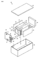
図6及び図7に、扁平型電池を複数含む電池パックの一例を示す。図6は、電池パックの分解斜視図である。図7は、図6の電池パックの電気回路を示すブロック図である。 6 and 7 show an example of a battery pack including a plurality of flat batteries. FIG. 6 is an exploded perspective view of the battery pack. FIG. 7 is a block diagram showing an electric circuit of the battery pack of FIG.
複数の単電池21は、外部に延出した正極端子18及び負極端子19が同じ向きに揃えられるように積層され、粘着テープ22で締結することにより組電池23を構成している。これらの単電池21は、図7に示すように互いに電気的に直列に接続されている。
The plurality of
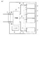
プリント配線基板24は、正極端子18及び負極端子19が延出する単電池21側面と対向して配置されている。プリント配線基板24には、図7に示すようにサーミスタ25、保護回路26及び外部機器への通電用端子27が搭載されている。なお、組電池23と対向するプリント配線基板24の面には組電池23の配線と不要な接続を回避するために絶縁板(図示せず)が取り付けられている。
The printed
正極側リード28は、組電池23の最下層に位置する正極端子18に接続され、その先端はプリント配線基板24の正極側コネクタ29に挿入されて電気的に接続されている。負極側リード30は、組電池23の最上層に位置する負極端子19に接続され、その先端はプリント配線基板24の負極側コネクタ31に挿入されて電気的に接続されている。これらのコネクタ29,31は、プリント配線基板24に形成された配線32,33を通して保護回路26に接続されている。
The positive
サーミスタ25は、単電池21の温度を検出するために用いられ、その検出信号は保護回路26に送信される。
The
保護回路26は、所定の条件で保護回路26と外部機器への通電用端子27との間のプラス側配線34a及びマイナス側配線34bを遮断できる。所定の条件とは、例えばサーミスタ25の検出温度が所定温度以上になったときである。或いは、所定の条件とは、単電池21の過充電、過放電、過電流等を検出したときである。この過充電等の検出は、個々の単電池21について行われてもよく、或いは、複数の単電池21全体について行われてもよい。個々の単電池21を検出する場合、電池電圧を検出してもよいし、正極電位もしくは負極電位を検出してもよい。後者の場合、個々の単電池21中に参照極として用いるリチウム電極が挿入される。図6及び図7の場合、単電池21それぞれに電圧検出のための配線38を接続し、これら配線38を通して検出信号が保護回路26に送信される。本実施形態の電池パックに備えられる電池は、電池電圧の検知による正極又は負極の電位の制御に優れるため、電池電圧を検知する保護回路が好適に用いられる。
The
正極端子18及び負極端子19が突出する側面を除く組電池23の三側面には、ゴムもしくは樹脂からなる保護シート35がそれぞれ配置されている。
組電池23は、各保護シート35及びプリント配線基板24と共に収納容器36内に収納される。すなわち、収納容器36の長辺方向の両方の内側面と短辺方向の一方の内側面それぞれに保護シート35が配置され、短辺方向の他方の内側面にプリント配線基板24が配置される。組電池23は、保護シート35及びプリント配線基板24で囲まれた空間内に位置する。蓋37は、収納容器36の上面に取り付けられている。
The assembled
なお、組電池23の固定には粘着テープ22に代えて、熱収縮テープを用いてもよい。この場合、組電池の両側面に保護シートを配置し、熱収縮テープを周回させた後、熱収縮テープを熱収縮させて組電池を結束させる。
In addition, instead of the
図6、図7では単電池21を直列接続した形態を示したが、電池容量を増大させるためには並列に接続しても、又は直列接続と並列接続を組み合わせてもよい。組み上がった電池パックをさらに直列、並列に接続することもできる。
6 and 7 show the configuration in which the
また、電池パックの態様は用途により適宜変更される。電池パックの用途は、大電流を取り出したときに優れたサイクル特性を示すものが好ましい。具体的には、デジタルカメラの電源用や、二輪乃至四輪のハイブリッド電気自動車、二輪乃至四輪の電気自動車、アシスト自転車等の車載用が挙げられる。特に、車載用が好適である。 Moreover, the aspect of a battery pack is changed suitably by a use. The battery pack is preferably one that exhibits excellent cycle characteristics when a large current is taken out. Specific examples include a power source for a digital camera, a vehicle for a two- to four-wheel hybrid electric vehicle, a two- to four-wheel electric vehicle, an assist bicycle, and the like. In particular, the vehicle-mounted one is suitable.
以上説明した実施形態によれば、放電容量を損なうことなく、充放電サイクル特性が向上された電池パックを提供することができる。 According to the embodiment described above, a battery pack having improved charge / discharge cycle characteristics can be provided without impairing the discharge capacity.
(実施例1)
<正極の作製>
正極活物質としてリチウムニッケルコバルトマンガン酸化物(LiNi0.8Co0.1Mn0.1O2)粉末を90質量%用い、導電剤として、アセチレンブラック5質量%とポリフッ化ビニリデン(PVdF)5質量%を用いた。これらの材料をN−メチルピロリドン(NMP)に加えて混合し、スラリーを調製した。このスラリーを厚さ15μmのアルミニウム箔からなる集電体の両面に塗布し後、乾燥し、プレスすることにより電極密度が3.2g/cm3の正極を作製した。
Example 1
<Preparation of positive electrode>
90% by mass of lithium nickel cobalt manganese oxide (LiNi 0.8 Co 0.1 Mn 0.1 O 2 ) powder was used as the positive electrode active material, and 5% by mass of acetylene black and 5% by mass of polyvinylidene fluoride (PVdF) were used as the conductive agent. These materials were added to N-methylpyrrolidone (NMP) and mixed to prepare a slurry. This slurry was applied to both surfaces of a current collector made of an aluminum foil having a thickness of 15 μm, dried, and pressed to prepare a positive electrode having an electrode density of 3.2 g / cm 3 .
<負極の作製>
第1の負極活物質として、平均粒径が15μmである単斜晶系β型チタン酸化物を用いた。該粒子は、平均繊維径が0.1μm、平均繊維長が1μmの繊維状一次粒子が凝集した凝集粒子である。そのN2吸着によるBET比表面積は18m2/gであった。
<Production of negative electrode>
A monoclinic β-type titanium oxide having an average particle size of 15 μm was used as the first negative electrode active material. The particles are aggregated particles obtained by aggregating fibrous primary particles having an average fiber diameter of 0.1 μm and an average fiber length of 1 μm. The BET specific surface area by the N 2 adsorption was 18 m 2 / g.
第2の負極活物質として、空間群Cmcaに属する結晶構造を有するLi2SrTi6O14の粒状粒子用いた。その平均粒径は3μmであった。そのLi吸蔵電位は1.45V(vs. Li/Li+)である。 As the second negative electrode active material, granular particles of Li 2 SrTi 6 O 14 having a crystal structure belonging to the space group Cmca were used. The average particle size was 3 μm. Its Li occlusion potential is 1.45 V (vs. Li / Li + ).
第1の負極活物質を100質量部、第2の負極活物質を2質量部、導電剤としてアセチレンブラックを10質量部、及び、ポリフッ化ビニリデン(PVdF)を10質量部用いた。これらの材料を、N−メチルピロリドン(NMP)加えて混合し、スラリーを調製した。このスラリーを厚さ15μmのアルミニウム箔(純度99.99質量%、平均結晶粒径10μm)からなる集電体の両面に塗布し、乾燥した後、プレスすることにより電極密度が2.3g/cm3の負極を作製した。 100 parts by mass of the first negative electrode active material, 2 parts by mass of the second negative electrode active material, 10 parts by mass of acetylene black as a conductive agent, and 10 parts by mass of polyvinylidene fluoride (PVdF) were used. These materials were added and mixed with N-methylpyrrolidone (NMP) to prepare a slurry. This slurry was applied to both sides of a current collector made of an aluminum foil having a thickness of 15 μm (purity: 99.99 mass%, average crystal grain size: 10 μm), dried, and pressed to have an electrode density of 2.3 g / cm. 3 negative electrodes were produced.
<第2の負極活物質のLi吸蔵電位の測定>
第2の負極活物質のLi吸蔵電位は以下に説明する方法で測定した。
<Measurement of Li storage potential of second negative electrode active material>
The Li storage potential of the second negative electrode active material was measured by the method described below.
まず、第2の負極活物質100質量部、導電剤として、アセチレンブラック10質量部と、ポリフッ化ビニリデン(PVdF)10質量部をN−メチルピロリドン(NMP)加えて混合してスラリーを調製した。このスラリーを用いたこと以外には前述したのと同様にして電極を作製した。この電極を2cm×2cmの大きさに切り出し、作用極とした。 First, 100 parts by mass of the second negative electrode active material, 10 parts by mass of acetylene black as a conductive agent, and 10 parts by mass of polyvinylidene fluoride (PVdF) were added to N-methylpyrrolidone (NMP) and mixed to prepare a slurry. An electrode was prepared in the same manner as described above except that this slurry was used. This electrode was cut into a size of 2 cm × 2 cm to obtain a working electrode.
作用極と2.2cm×2.2cmのリチウム金属箔からなる対極とをグラスフィルター(セパレータ)を介して対向させ、作用極と対極とに触れぬようにリチウム金属を参照極として挿入した。これら電極を3極式ガラスセルに入れ、作用極、対極、参照極の夫々をガラスセルの端子に接続し、電解液を25mL注ぎ、セパレータと電極に充分に電解液が含浸された状態にし、ガラス容器を密閉した。 The working electrode and a counter electrode made of a 2.2 cm × 2.2 cm lithium metal foil were opposed to each other through a glass filter (separator), and lithium metal was inserted as a reference electrode so as not to touch the working electrode and the counter electrode. Put these electrodes in a three-electrode glass cell, connect each of the working electrode, counter electrode, and reference electrode to the terminals of the glass cell, pour 25 mL of the electrolyte, and make the separator and the electrode sufficiently impregnated with the electrolyte, The glass container was sealed.
なお、電解液は、エチレンカーボネートとジエチルカーボネートを1:2の体積比で混合した混合溶媒に1Mの六フッ化リン酸リチウム(LiPF6)を溶解させて調製した。 The electrolytic solution was prepared by dissolving 1M lithium hexafluorophosphate (LiPF 6 ) in a mixed solvent in which ethylene carbonate and diethyl carbonate were mixed at a volume ratio of 1: 2.
作製したガラスセルを25℃の恒温槽内に配置し、0.1mA/cm2の電流密度で充電した際の作用極のリチウムイオン吸蔵電位を測定した。 The produced glass cell was placed in a constant temperature bath at 25 ° C., and the lithium ion occlusion potential of the working electrode when charged at a current density of 0.1 mA / cm 2 was measured.
<電極群の作製>
正極、厚さ20μmのポリエチレン製の多孔質フィルムからなるセパレータ、負極、セパレータの順番に積層した後、渦巻き状に捲回した。これを90℃で加熱プレスすることにより、幅が30mmで、厚さが3.0mmの偏平状電極群を作製した。得られた電極群を、厚さが40μmのアルミニウム箔とアルミニウム箔の両面に形成されたポリプロピレン層とから構成された厚さが0.1mmのラミネートフィルムからなるパックに収納し、80℃で24時間真空乾燥を施した。
<Production of electrode group>
After laminating a positive electrode, a separator made of a polyethylene porous film having a thickness of 20 μm, a negative electrode, and a separator in this order, the film was wound in a spiral shape. This was heated and pressed at 90 ° C. to produce a flat electrode group having a width of 30 mm and a thickness of 3.0 mm. The obtained electrode group was housed in a pack made of a laminate film having a thickness of 0.1 mm and composed of an aluminum foil having a thickness of 40 μm and a polypropylene layer formed on both surfaces of the aluminum foil. Vacuum drying was performed for hours.
<液状非水電解質の調製>
エチレンカーボネート(EC)、ジエチルカーボネート(DEC)が体積比率(EC:DEC)1:2で混合された混合溶媒に、電解質としてのLiPF6を1mol/L溶解することにより液状非水電解質を調製した。
<Preparation of liquid nonaqueous electrolyte>
A liquid non-aqueous electrolyte was prepared by dissolving 1 mol / L of LiPF 6 as an electrolyte in a mixed solvent in which ethylene carbonate (EC) and diethyl carbonate (DEC) were mixed at a volume ratio (EC: DEC) of 1: 2. .
<非水電解質二次電池の作製>
電極群をラミネートフィルムパック内に収納し、さらに液状非水電解質を注入した後、パックをヒートシールにより完全密閉し、図2に示す構造を有し、幅が35mmで、厚さが3.2mm、かつ高さが65mmの非水電解質二次電池を作製した。
<Preparation of nonaqueous electrolyte secondary battery>
The electrode group is housed in a laminate film pack, and after the liquid nonaqueous electrolyte is injected, the pack is completely sealed by heat sealing, and has the structure shown in FIG. 2, having a width of 35 mm and a thickness of 3.2 mm. A nonaqueous electrolyte secondary battery having a height of 65 mm was produced.
(実施例2〜6、比較例1)
第1の負極活物質と第2の負極活物質の質量比(A/B)を表1に記載したように変更した以外は、実施例1と同様にして非水電解質二次電池を作製した。
(Examples 2-6, Comparative Example 1)
A nonaqueous electrolyte secondary battery was produced in the same manner as in Example 1 except that the mass ratio (A / B) of the first negative electrode active material and the second negative electrode active material was changed as described in Table 1. .
(実施例7〜11)
第2の負極活物質として空間群P21/CのMoO2を用い、第1の負極活物質と第2の負極活物質の質量比(A/B)を表1に記載したように変更した以外は、実施例1と同様にして非水電解質二次電池を作製した。
(Examples 7 to 11)
Using MoO 2 in the space group P2 1 / C as the second negative electrode active material, the mass ratio (A / B) between the first negative electrode active material and the second negative electrode active material was changed as described in Table 1. A nonaqueous electrolyte secondary battery was produced in the same manner as Example 1 except for the above.
(実施例12〜17)
正極活物質、第2の負極活物質として表1に記載したものを用いた以外は、実施例1と同様にして非水電解質二次電池を作製した。
(Examples 12 to 17)
A nonaqueous electrolyte secondary battery was produced in the same manner as in Example 1 except that the positive electrode active material and the second negative electrode active material described in Table 1 were used.
<充放電サイクル試験>
実施例1〜17及び比較例1の電池を用いてサイクル特性を評価した。25℃環境下において、1C電流2.8Vの定電流定電圧充電で2時間充電と、1C1.5Vの定電流放電を1サイクルとして、充放電サイクル試験を行い、初回容量に対する500サイクル目の容量の比(%)を測定した。また、60℃環境下において、同様のサイクル試験を行った。その結果を表1に示す。
The cycle characteristics were evaluated using the batteries of Examples 1 to 17 and Comparative Example 1. In a 25 ° C environment, a charge / discharge cycle test was conducted with a constant current / constant voltage charge of 1C current 2.8V for 2 hours and a constant current discharge of 1C 1.5V as one cycle. The ratio (%) of was measured. Moreover, the same cycle test was done in a 60 degreeC environment. The results are shown in Table 1.
比較例1の電池は、60℃において、500サイクル後の容量比が0であり、高温環境下で著しく容量が低下することが示されている。一方、実施例1〜17の電池は、何れも60℃において500サイクル後の容量比が比較例1よりも顕著に高かった。よって、本実施形態に従って、負極に第2の負極活物質を用いることにより、高温環境下におけるサイクル特性が著しく向上することが示された。また、特にA/Bが20以上である場合に、500サイクル後の容量比が高かった。よって、第2の負極活物質が一定以上の割合で存在することにより、サイクル特性を向上させる効果がより顕著に得られることが分かった。 The battery of Comparative Example 1 has a capacity ratio of 0 after 500 cycles at 60 ° C., and it is shown that the capacity is significantly reduced under a high temperature environment. On the other hand, the batteries of Examples 1 to 17 all had a significantly higher capacity ratio after 500 cycles at 60 ° C. than Comparative Example 1. Therefore, according to this embodiment, it was shown that the cycle characteristics under a high temperature environment are remarkably improved by using the second negative electrode active material for the negative electrode. In particular, when A / B was 20 or more, the capacity ratio after 500 cycles was high. Therefore, it has been found that the presence of the second negative electrode active material at a certain ratio or more can provide a more remarkable effect of improving the cycle characteristics.
本発明のいくつかの実施形態を説明したが、これらの実施形態は、例として提示したものであり、発明の範囲を限定することは意図していない。これら新規な実施形態は、その他の様々な形態で実施されることが可能であり、発明の要旨を逸脱しない範囲で、種々の省略、置き換え、変更を行うことができる。これら実施形態やその変形は、発明の範囲や要旨に含まれるとともに、特許請求の範囲に記載された発明とその均等の範囲に含まれる。
[付記]以下に、出願当初の特許請求の範囲に記載された発明を付記する。
[項1] 正極と、負極と、非水電解質と、を具備し、前記負極は、単斜晶系β型チタン複合酸化物を含む第1の負極活物質と、0.8V以上1.5V以下(vs Li/Li + )の範囲でLiを吸蔵・放出する第2の負極活物質とを含むことを特徴とする非水電解質電池。
[項2] 前記第2の負極活物質は、LixMoOy(0≦x≦2、1.9≦y≦2.1)で表される酸化物、及び、空間群Cmcaに属する結晶構造を有し、Li 2+x A y Ti 6 O 14 (ここで、AはNa、K、Mg、Ca、Ba及びSrよりなる群から選択される少なくとも1種の元素であり、0≦x≦5、1≦y≦2である)で表される酸化物から選択される遷移金属含有酸化物であることを特徴とする、項1に記載の非水電解質電池。
[項3] 前記第2の負極活物質は、Fe、Co、Ni、Cu及びMoからなる群から選択される少なくとも1種の元素を含む遷移金属含有酸化物であることを特徴とする、項1に記載の非水電解質電池。
[項4] 前記第2の負極活物質は、モリブデン酸化物であることを特徴とする項1〜3の何れか一項に記載の非水電解質電池。
[項5] 前記第2の負極活物質は、空間群Cmcaに属する結晶構造を有するチタン含有酸化物であることを特徴とする、項1又は2に記載の非水電解質二次電池。
[項6] 前記負極における前記第1の負極活物質と第2の負極活物質の質量比が式(I)を満たすことを特徴とする、項1〜5の何れか一項に記載の非水電解質電池:
1≦(A/B)≦100 (I)
式中、Aは前記第1の負極活物質の負極単位面積当たりの質量であり、Bは前記第2の負極活物質の負極単位面積当たりの質量である。
[項7] 前記正極は、ニッケルを含有するリチウム複合酸化物を含むことを特徴とする項1〜6の何れか一項に記載の非水電解質電池。
[項8] 前記正極は、式(II)で表されるリチウム金属酸化物を含むことを特徴とする項1〜6の何れか一項に記載の非水電解質電池:
xLi 2 MeO 3 - (1-x)LiMe'O 2 (II)
式中、0<x<1であり、Me及びMe'はそれぞれ独立的に、Mn、Ti、Zr、V、Cr、Fe、Co、Ni、Cu、Al、Mg、Zr、B及びMoからなる群から選択される少なくとも1種の元素である。
[項9] 項1〜8の何れか一項に記載の非水電解質電池を具備することを特徴とする電池パック。
Although several embodiments of the present invention have been described, these embodiments are presented by way of example and are not intended to limit the scope of the invention. These novel embodiments can be implemented in various other forms, and various omissions, replacements, and changes can be made without departing from the scope of the invention. These embodiments and modifications thereof are included in the scope and gist of the invention, and are included in the invention described in the claims and the equivalents thereof.
[Appendix] The invention described in the claims at the beginning of the application will be added below.
[Item 1] A positive electrode, a negative electrode, and a non-aqueous electrolyte are provided, and the negative electrode includes a first negative electrode active material containing a monoclinic β-type titanium composite oxide, 0.8 V to 1.5 V A nonaqueous electrolyte battery comprising a second negative electrode active material that occludes and releases Li in the range of (vs Li / Li + ) below .
[Item 2] The second negative electrode active material has an oxide represented by LixMoOy (0 ≦ x ≦ 2, 1.9 ≦ y ≦ 2.1) and a crystal structure belonging to the space group Cmca, and Li 2+ x A y Ti 6 O 14 (where A is at least one element selected from the group consisting of Na, K, Mg, Ca, Ba and Sr, and 0 ≦ x ≦ 5, 1 ≦ y ≦ 2 The non-aqueous electrolyte battery according to
[Item 3] The second negative electrode active material is a transition metal-containing oxide containing at least one element selected from the group consisting of Fe, Co, Ni, Cu, and Mo. 1. The nonaqueous electrolyte battery according to 1.
[Item 4] The nonaqueous electrolyte battery according to any one of
[Item 5] The nonaqueous electrolyte secondary battery according to
CLAIM |
1 ≦ (A / B) ≦ 100 (I)
In the formula, A is the mass per negative electrode unit area of the first negative electrode active material, and B is the mass per negative electrode unit area of the second negative electrode active material.
[Item 7] The nonaqueous electrolyte battery according to any one of
[Item 8] The nonaqueous electrolyte battery according to any one of
xLi 2 MeO 3- (1-x) LiMe'O 2 (II)
In the formula, 0 <x <1, and Me and Me ′ are independently composed of Mn, Ti, Zr, V, Cr, Fe, Co, Ni, Cu, Al, Mg, Zr, B, and Mo. At least one element selected from the group.
[Item 9] A battery pack comprising the nonaqueous electrolyte battery according to any one of
1,10…電池、2,12…外装部材、3…捲回電極群、4…正極、4a…正極集電体、4b…正極活物質層、5…負極、5a…負極集電体、5b…負極活物質層、6…セパレータ、7,13…正極端子、8,14…負極端子、11…積層型電極群、20…電池パック、21…電池単体、22…組電池、23…粘着テープ、24…プリント配線基板、25…サーミスタ、26…保護回路、27…端子、28…正極側配線、29…正極側コネクタ、30…負極側配線、31…負極側コネクタ、31a…プラス側配線、31b…マイナス側配線、32,33…配線、35…保護シート、36…収納容器、37…蓋。
DESCRIPTION OF
Claims (9)
負極と、
非水電解質と、
を具備し、
前記負極は、単斜晶系β型チタン複合酸化物及び単斜晶系β型チタン酸化物から選択される酸化物を含む第1の負極活物質と、0.8V以上1.5V以下(vs Li/Li+)の範囲でLiを吸蔵・放出する第2の負極活物質とを含むことを特徴とする非水電解質電池。 A positive electrode;
A negative electrode,
A non-aqueous electrolyte,
Comprising
The negative electrode includes a first negative electrode active material containing an oxide selected from a monoclinic β-type titanium composite oxide and a monoclinic β-type titanium oxide , 0.8 V to 1.5 V (vs And a second negative electrode active material that occludes and releases Li in the range of Li / Li + ).
1≦(A/B)≦100 (I)
式中、
Aは前記第1の負極活物質の負極単位面積当たりの質量であり、
Bは前記第2の負極活物質の負極単位面積当たりの質量である。 The nonaqueous electrolyte battery according to claim 1, wherein a mass ratio of the first negative electrode active material and the second negative electrode active material in the negative electrode satisfies Formula (I). :
1 ≦ (A / B) ≦ 100 (I)
Where
A is the mass per unit area of the negative electrode of the first negative electrode active material,
B is the mass per unit area of the negative electrode of the second negative electrode active material.
xLi2MeO3 - (1-x)LiMe'O2 (II)
式中、0<x<1であり、
Me及びMe'はそれぞれ独立的に、Mn、Ti、Zr、V、Cr、Fe、Co、Ni、Cu、Al、Mg、Zr、B及びMoからなる群から選択される少なくとも1種の元素である。 The non-aqueous electrolyte battery according to any one of claims 1 to 6, wherein the positive electrode contains a lithium metal oxide represented by the formula (II):
xLi 2 MeO 3- (1-x) LiMe'O 2 (II)
Where 0 <x <1,
Me and Me ′ are each independently at least one element selected from the group consisting of Mn, Ti, Zr, V, Cr, Fe, Co, Ni, Cu, Al, Mg, Zr, B, and Mo. is there.
Priority Applications (3)
| Application Number | Priority Date | Filing Date | Title |
|---|---|---|---|
| JP2011139202A JP5586532B2 (en) | 2011-06-23 | 2011-06-23 | Nonaqueous electrolyte battery and battery pack |
| US13/429,554 US9331332B2 (en) | 2011-06-23 | 2012-03-26 | Nonaqueous electrolyte battery and battery pack |
| CN201210082564.5A CN102842742B (en) | 2011-06-23 | 2012-03-26 | Nonaqueous electrolyte battery and battery pack |
Applications Claiming Priority (1)
| Application Number | Priority Date | Filing Date | Title |
|---|---|---|---|
| JP2011139202A JP5586532B2 (en) | 2011-06-23 | 2011-06-23 | Nonaqueous electrolyte battery and battery pack |
Publications (2)
| Publication Number | Publication Date |
|---|---|
| JP2013008493A JP2013008493A (en) | 2013-01-10 |
| JP5586532B2 true JP5586532B2 (en) | 2014-09-10 |
Family
ID=47362134
Family Applications (1)
| Application Number | Title | Priority Date | Filing Date |
|---|---|---|---|
| JP2011139202A Expired - Fee Related JP5586532B2 (en) | 2011-06-23 | 2011-06-23 | Nonaqueous electrolyte battery and battery pack |
Country Status (3)
| Country | Link |
|---|---|
| US (1) | US9331332B2 (en) |
| JP (1) | JP5586532B2 (en) |
| CN (1) | CN102842742B (en) |
Cited By (2)
| Publication number | Priority date | Publication date | Assignee | Title |
|---|---|---|---|---|
| US10020504B2 (en) | 2015-09-16 | 2018-07-10 | Kabushiki Kaisha Toshiba | Active material, nonaqueous electrolyte battery, battery pack, and vehicle |
| US10553868B2 (en) | 2014-12-02 | 2020-02-04 | Kabushiki Kaisha Toshiba | Negative electrode active material, nonaqueous electrolyte battery, battery pack and vehicle |
Families Citing this family (35)
| Publication number | Priority date | Publication date | Assignee | Title |
|---|---|---|---|---|
| KR101075304B1 (en) * | 2009-10-09 | 2011-10-19 | 삼성에스디아이 주식회사 | Battery pack and manufacture method thereof |
| JP5877898B2 (en) * | 2012-05-31 | 2016-03-08 | 株式会社日立製作所 | Positive electrode active material for lithium ion secondary battery |
| US11387497B2 (en) | 2012-10-18 | 2022-07-12 | Ambri Inc. | Electrochemical energy storage devices |
| US11211641B2 (en) | 2012-10-18 | 2021-12-28 | Ambri Inc. | Electrochemical energy storage devices |
| US11721841B2 (en) | 2012-10-18 | 2023-08-08 | Ambri Inc. | Electrochemical energy storage devices |
| JP2014154317A (en) * | 2013-02-07 | 2014-08-25 | Toshiba Corp | Electrode, nonaqueous electrolyte battery and battery pack |
| US9899703B2 (en) * | 2013-03-01 | 2018-02-20 | Nec Corporation | Gel electrolyte and polymer secondary battery using same |
| JP6058444B2 (en) * | 2013-03-26 | 2017-01-11 | 株式会社東芝 | Negative electrode, non-aqueous electrolyte battery, battery pack and automobile |
| DK3058605T3 (en) | 2013-10-16 | 2024-03-04 | Ambri Inc | SEALS FOR DEVICES OF REACTIVE HIGH TEMPERATURE MATERIAL |
| JP6334308B2 (en) * | 2014-07-31 | 2018-05-30 | 株式会社東芝 | Non-aqueous electrolyte battery, battery pack, and car |
| KR101880872B1 (en) * | 2014-11-27 | 2018-07-20 | 가부시끼가이샤 도시바 | Active material for batteries, nonaqueous electrolyte battery, assembled battery, battery pack and automobile |
| JP6593345B2 (en) * | 2014-12-16 | 2019-10-23 | 株式会社村田製作所 | Secondary battery electrolyte, secondary battery, battery pack, electric vehicle, power storage system, electric tool and electronic device |
| EP3147974B1 (en) | 2015-01-30 | 2019-02-27 | Kabushiki Kaisha Toshiba | Battery module and battery pack |
| CN105845922B (en) | 2015-01-30 | 2018-11-09 | 株式会社东芝 | Active material, nonaqueous electrolyte battery, battery pack and battery pack |
| JP6169246B2 (en) * | 2015-02-16 | 2017-07-26 | 株式会社東芝 | Nonaqueous electrolyte battery and battery pack |
| WO2016141354A2 (en) | 2015-03-05 | 2016-09-09 | Ambri Inc. | Ceramic materials and seals for high temperature reactive material devices |
| JP6067902B2 (en) | 2015-03-13 | 2017-01-25 | 株式会社東芝 | Active materials, non-aqueous electrolyte batteries, battery packs, assembled batteries, and automobiles |
| JP6426509B2 (en) * | 2015-03-13 | 2018-11-21 | 株式会社東芝 | Battery active materials, non-aqueous electrolyte batteries, assembled batteries, battery packs and automobiles |
| JP6632233B2 (en) * | 2015-07-09 | 2020-01-22 | マクセルホールディングス株式会社 | Non-aqueous electrolyte secondary battery |
| JP6659274B2 (en) | 2015-08-25 | 2020-03-04 | 株式会社東芝 | Negative electrode active material for non-aqueous electrolyte battery, negative electrode, non-aqueous electrolyte battery, assembled battery, battery pack, and automobile |
| JP6659282B2 (en) | 2015-09-09 | 2020-03-04 | 株式会社東芝 | Active material for battery, negative electrode, non-aqueous electrolyte battery, battery pack and car |
| JP6594132B2 (en) | 2015-09-15 | 2019-10-23 | 株式会社東芝 | Battery active material, negative electrode, non-aqueous electrolyte battery, battery pack and vehicle |
| JP6523892B2 (en) * | 2015-09-16 | 2019-06-05 | 株式会社東芝 | Electrode, non-aqueous electrolyte battery, battery pack and car |
| JP6567447B2 (en) | 2016-03-15 | 2019-08-28 | 株式会社東芝 | Active material for lithium ion secondary battery, negative electrode, non-aqueous electrolyte battery, battery pack, and vehicle |
| JP6633434B2 (en) * | 2016-03-16 | 2020-01-22 | 株式会社東芝 | Negative electrode active material for lithium ion secondary battery, negative electrode for lithium ion secondary battery, lithium ion secondary battery, battery pack and vehicle |
| JP6696689B2 (en) | 2016-03-16 | 2020-05-20 | 株式会社東芝 | Active materials, electrodes, non-aqueous electrolyte batteries, battery packs, and vehicles |
| JP6577396B2 (en) * | 2016-03-16 | 2019-09-18 | 株式会社東芝 | Active material, electrode, non-aqueous electrolyte battery, battery pack, and vehicle |
| JP6612662B2 (en) * | 2016-03-16 | 2019-11-27 | 株式会社東芝 | Negative electrode active material for lithium ion secondary battery, negative electrode for lithium ion secondary battery, lithium ion secondary battery, battery pack and vehicle |
| US11929466B2 (en) | 2016-09-07 | 2024-03-12 | Ambri Inc. | Electrochemical energy storage devices |
| JP6659504B2 (en) * | 2016-09-20 | 2020-03-04 | 株式会社東芝 | Solid electrolyte, lithium battery, battery pack, and vehicle |
| CN106602052B (en) * | 2016-12-28 | 2019-01-29 | 宁波大学 | A kind of lithium ion battery negative material and preparation method thereof |
| JP6622242B2 (en) * | 2017-03-24 | 2019-12-18 | 株式会社東芝 | Electrode structure, electrode, secondary battery, battery pack, battery pack, and vehicle |
| CN110731027A (en) | 2017-04-07 | 2020-01-24 | 安保瑞公司 | Molten salt battery with solid metal cathode |
| JP7067985B2 (en) * | 2018-03-22 | 2022-05-16 | 株式会社東芝 | Rechargeable batteries, battery packs, vehicles, and stationary power supplies |
| US10873080B2 (en) * | 2018-03-22 | 2020-12-22 | Kabushiki Kaisha Toshiba | Secondary battery, battery pack, vehicle, and stationary power supply |
Family Cites Families (12)
| Publication number | Priority date | Publication date | Assignee | Title |
|---|---|---|---|---|
| US7390594B2 (en) * | 2002-12-19 | 2008-06-24 | Uchicago Argonne, Llc | Anode material for lithium batteries |
| JP4237659B2 (en) * | 2004-03-17 | 2009-03-11 | 株式会社東芝 | Non-aqueous electrolyte battery |
| CN101160677A (en) * | 2004-10-21 | 2008-04-09 | 德古萨有限责任公司 | Inorganic separator-electrode-unit for lithium-ion batteries, method for the production thereof and use thereof in lithium batteries |
| FR2902577B1 (en) | 2006-06-20 | 2009-04-24 | Commissariat Energie Atomique | LITHIUM ION BATTERY COMPRISING TIO2-B AS AN ACTIVE NEGATIVE ELECTRODE MATERIAL |
| FR2932175B1 (en) * | 2008-06-05 | 2011-06-03 | Commissariat Energie Atomique | POSITIVE ELECTRODE MATERIAL FORMED OF A LAMELLAR TYPE OXIDE FOR LITHIUM ACCUMULATOR. |
| JP2010086896A (en) * | 2008-10-02 | 2010-04-15 | Sanyo Electric Co Ltd | Nonaqueous electrolyte secondary battery and active material for nonaqueous electrolyte secondary battery |
| JP5438299B2 (en) * | 2008-10-14 | 2014-03-12 | 株式会社東芝 | Nonaqueous electrolyte battery and battery pack |
| JP5319312B2 (en) * | 2009-01-21 | 2013-10-16 | 株式会社東芝 | Negative electrode active material for batteries, non-aqueous electrolyte battery and battery pack |
| JP5159681B2 (en) * | 2009-03-25 | 2013-03-06 | 株式会社東芝 | Non-aqueous electrolyte battery |
| CN102334219B (en) * | 2009-05-15 | 2014-07-23 | 株式会社东芝 | Battery with nonaqueous electrolyte, negative electrode active material for use in the battery, and battery pack |
| JP5284221B2 (en) | 2009-08-20 | 2013-09-11 | 株式会社東芝 | Nonaqueous electrolyte battery and battery pack |
| KR20110127209A (en) * | 2010-03-15 | 2011-11-24 | 파나소닉 주식회사 | Electrode for non-aqueous electrolyte secondary battery and non-aqueous electrolyte secondary battery including the same |
-
2011
- 2011-06-23 JP JP2011139202A patent/JP5586532B2/en not_active Expired - Fee Related
-
2012
- 2012-03-26 US US13/429,554 patent/US9331332B2/en active Active
- 2012-03-26 CN CN201210082564.5A patent/CN102842742B/en not_active Expired - Fee Related
Cited By (2)
| Publication number | Priority date | Publication date | Assignee | Title |
|---|---|---|---|---|
| US10553868B2 (en) | 2014-12-02 | 2020-02-04 | Kabushiki Kaisha Toshiba | Negative electrode active material, nonaqueous electrolyte battery, battery pack and vehicle |
| US10020504B2 (en) | 2015-09-16 | 2018-07-10 | Kabushiki Kaisha Toshiba | Active material, nonaqueous electrolyte battery, battery pack, and vehicle |
Also Published As
| Publication number | Publication date |
|---|---|
| CN102842742A (en) | 2012-12-26 |
| US20120328930A1 (en) | 2012-12-27 |
| JP2013008493A (en) | 2013-01-10 |
| US9331332B2 (en) | 2016-05-03 |
| CN102842742B (en) | 2015-12-02 |
Similar Documents
| Publication | Publication Date | Title |
|---|---|---|
| JP5586532B2 (en) | Nonaqueous electrolyte battery and battery pack | |
| US10673103B2 (en) | Battery module, battery pack and vehicle | |
| JP4625744B2 (en) | Nonaqueous electrolyte battery and battery pack | |
| JP5184846B2 (en) | Nonaqueous electrolyte battery and battery pack | |
| JP5178111B2 (en) | Non-aqueous electrolyte battery and pack battery | |
| JP4439456B2 (en) | Battery pack and automobile | |
| JP5438299B2 (en) | Nonaqueous electrolyte battery and battery pack | |
| JP4950980B2 (en) | Lithium titanium composite oxide for nonaqueous electrolyte battery and negative electrode active material for nonaqueous electrolyte battery | |
| JP5221692B2 (en) | Nonaqueous electrolyte battery and battery pack | |
| JP5694221B2 (en) | Nonaqueous electrolyte battery and battery pack | |
| JP6441125B2 (en) | Nonaqueous electrolyte battery and battery pack | |
| JP6334308B2 (en) | Non-aqueous electrolyte battery, battery pack, and car | |
| JP5734813B2 (en) | Battery electrode, non-aqueous electrolyte battery, and battery pack | |
| JP2014154317A (en) | Electrode, nonaqueous electrolyte battery and battery pack | |
| JP2017168255A (en) | Nonaqueous electrolyte secondary battery, battery pack, and vehicle | |
| JP2016033898A (en) | Nonaqueous electrolyte battery and battery pack | |
| JP6058444B2 (en) | Negative electrode, non-aqueous electrolyte battery, battery pack and automobile | |
| JP5535160B2 (en) | Nonaqueous electrolyte battery and battery pack | |
| JP4836612B2 (en) | Nonaqueous electrolyte battery and battery pack | |
| JP7021364B2 (en) | Non-aqueous electrolyte batteries and battery packs | |
| JP6054540B2 (en) | Positive electrode active material, non-aqueous electrolyte battery, and battery pack | |
| JP6113852B2 (en) | Non-aqueous electrolyte battery, battery pack and car | |
| JP5774670B2 (en) | Nonaqueous electrolyte battery and battery pack | |
| JP5851547B2 (en) | Nonaqueous electrolyte battery and battery pack | |
| JP5361940B2 (en) | Nonaqueous electrolyte battery and battery pack |
Legal Events
| Date | Code | Title | Description |
|---|---|---|---|
| A621 | Written request for application examination |
Free format text: JAPANESE INTERMEDIATE CODE: A621 Effective date: 20131001 |
|
| RD04 | Notification of resignation of power of attorney |
Free format text: JAPANESE INTERMEDIATE CODE: A7424 Effective date: 20131205 |
|
| RD04 | Notification of resignation of power of attorney |
Free format text: JAPANESE INTERMEDIATE CODE: A7424 Effective date: 20131212 |
|
| RD04 | Notification of resignation of power of attorney |
Free format text: JAPANESE INTERMEDIATE CODE: A7424 Effective date: 20131219 |
|
| RD04 | Notification of resignation of power of attorney |
Free format text: JAPANESE INTERMEDIATE CODE: A7424 Effective date: 20131226 |
|
| RD04 | Notification of resignation of power of attorney |
Free format text: JAPANESE INTERMEDIATE CODE: A7424 Effective date: 20140109 |
|
| A977 | Report on retrieval |
Free format text: JAPANESE INTERMEDIATE CODE: A971007 Effective date: 20140312 |
|
| A131 | Notification of reasons for refusal |
Free format text: JAPANESE INTERMEDIATE CODE: A131 Effective date: 20140401 |
|
| A521 | Request for written amendment filed |
Free format text: JAPANESE INTERMEDIATE CODE: A523 Effective date: 20140602 |
|
| TRDD | Decision of grant or rejection written | ||
| A01 | Written decision to grant a patent or to grant a registration (utility model) |
Free format text: JAPANESE INTERMEDIATE CODE: A01 Effective date: 20140624 |
|
| A61 | First payment of annual fees (during grant procedure) |
Free format text: JAPANESE INTERMEDIATE CODE: A61 Effective date: 20140722 |
|
| R151 | Written notification of patent or utility model registration |
Ref document number: 5586532 Country of ref document: JP Free format text: JAPANESE INTERMEDIATE CODE: R151 |
|
| LAPS | Cancellation because of no payment of annual fees |