JP5583153B2 - Liquid level detection device and method - Google Patents
Liquid level detection device and method Download PDFInfo
- Publication number
- JP5583153B2 JP5583153B2 JP2012014554A JP2012014554A JP5583153B2 JP 5583153 B2 JP5583153 B2 JP 5583153B2 JP 2012014554 A JP2012014554 A JP 2012014554A JP 2012014554 A JP2012014554 A JP 2012014554A JP 5583153 B2 JP5583153 B2 JP 5583153B2
- Authority
- JP
- Japan
- Prior art keywords
- liquid level
- signal
- liquid
- unit
- probe
- Prior art date
- Legal status (The legal status is an assumption and is not a legal conclusion. Google has not performed a legal analysis and makes no representation as to the accuracy of the status listed.)
- Active
Links
Images


Classifications
-
- G—PHYSICS
- G01—MEASURING; TESTING
- G01F—MEASURING VOLUME, VOLUME FLOW, MASS FLOW OR LIQUID LEVEL; METERING BY VOLUME
- G01F23/00—Indicating or measuring liquid level or level of fluent solid material, e.g. indicating in terms of volume or indicating by means of an alarm
- G01F23/22—Indicating or measuring liquid level or level of fluent solid material, e.g. indicating in terms of volume or indicating by means of an alarm by measuring physical variables, other than linear dimensions, pressure or weight, dependent on the level to be measured, e.g. by difference of heat transfer of steam or water
- G01F23/24—Indicating or measuring liquid level or level of fluent solid material, e.g. indicating in terms of volume or indicating by means of an alarm by measuring physical variables, other than linear dimensions, pressure or weight, dependent on the level to be measured, e.g. by difference of heat transfer of steam or water by measuring variations of resistance of resistors due to contact with conductor fluid
- G01F23/241—Indicating or measuring liquid level or level of fluent solid material, e.g. indicating in terms of volume or indicating by means of an alarm by measuring physical variables, other than linear dimensions, pressure or weight, dependent on the level to be measured, e.g. by difference of heat transfer of steam or water by measuring variations of resistance of resistors due to contact with conductor fluid for discrete levels
- G01F23/243—Schematic arrangements of probes combined with measuring circuits
-
- G—PHYSICS
- G01—MEASURING; TESTING
- G01F—MEASURING VOLUME, VOLUME FLOW, MASS FLOW OR LIQUID LEVEL; METERING BY VOLUME
- G01F23/00—Indicating or measuring liquid level or level of fluent solid material, e.g. indicating in terms of volume or indicating by means of an alarm
- G01F23/22—Indicating or measuring liquid level or level of fluent solid material, e.g. indicating in terms of volume or indicating by means of an alarm by measuring physical variables, other than linear dimensions, pressure or weight, dependent on the level to be measured, e.g. by difference of heat transfer of steam or water
- G01F23/24—Indicating or measuring liquid level or level of fluent solid material, e.g. indicating in terms of volume or indicating by means of an alarm by measuring physical variables, other than linear dimensions, pressure or weight, dependent on the level to be measured, e.g. by difference of heat transfer of steam or water by measuring variations of resistance of resistors due to contact with conductor fluid
- G01F23/246—Indicating or measuring liquid level or level of fluent solid material, e.g. indicating in terms of volume or indicating by means of an alarm by measuring physical variables, other than linear dimensions, pressure or weight, dependent on the level to be measured, e.g. by difference of heat transfer of steam or water by measuring variations of resistance of resistors due to contact with conductor fluid thermal devices
- G01F23/247—Indicating or measuring liquid level or level of fluent solid material, e.g. indicating in terms of volume or indicating by means of an alarm by measuring physical variables, other than linear dimensions, pressure or weight, dependent on the level to be measured, e.g. by difference of heat transfer of steam or water by measuring variations of resistance of resistors due to contact with conductor fluid thermal devices for discrete levels
- G01F23/248—Constructional details; Mounting of probes
-
- G—PHYSICS
- G21—NUCLEAR PHYSICS; NUCLEAR ENGINEERING
- G21C—NUCLEAR REACTORS
- G21C17/00—Monitoring; Testing ; Maintaining
- G21C17/02—Devices or arrangements for monitoring coolant or moderator
- G21C17/035—Moderator- or coolant-level detecting devices
-
- G—PHYSICS
- G21—NUCLEAR PHYSICS; NUCLEAR ENGINEERING
- G21C—NUCLEAR REACTORS
- G21C19/00—Arrangements for treating, for handling, or for facilitating the handling of, fuel or other materials which are used within the reactor, e.g. within its pressure vessel
- G21C19/02—Details of handling arrangements
- G21C19/06—Magazines for holding fuel elements or control elements
- G21C19/07—Storage racks; Storage pools
-
- Y—GENERAL TAGGING OF NEW TECHNOLOGICAL DEVELOPMENTS; GENERAL TAGGING OF CROSS-SECTIONAL TECHNOLOGIES SPANNING OVER SEVERAL SECTIONS OF THE IPC; TECHNICAL SUBJECTS COVERED BY FORMER USPC CROSS-REFERENCE ART COLLECTIONS [XRACs] AND DIGESTS
- Y02—TECHNOLOGIES OR APPLICATIONS FOR MITIGATION OR ADAPTATION AGAINST CLIMATE CHANGE
- Y02E—REDUCTION OF GREENHOUSE GAS [GHG] EMISSIONS, RELATED TO ENERGY GENERATION, TRANSMISSION OR DISTRIBUTION
- Y02E30/00—Energy generation of nuclear origin
- Y02E30/30—Nuclear fission reactors
Landscapes
- Physics & Mathematics (AREA)
- Engineering & Computer Science (AREA)
- Thermal Sciences (AREA)
- Fluid Mechanics (AREA)
- General Physics & Mathematics (AREA)
- Plasma & Fusion (AREA)
- General Engineering & Computer Science (AREA)
- High Energy & Nuclear Physics (AREA)
- Measurement Of Levels Of Liquids Or Fluent Solid Materials (AREA)
Description
本発明は、容器に保持されている液体の液面レベルを検知する技術に関する。 The present invention relates to a technique for detecting a liquid level of a liquid held in a container.
使用済み燃料貯蔵プールでは、水による放射線の遮へい効果を確保するため、基準レベル、例えば使用済み燃料集合体の長さの2倍強程度の液面レベルよりも低下しないように監視運用している。
従来における使用済み燃料貯蔵プールの液面レベルは、プール上端部にフロート式レベルスイッチを設置して計測していた。また、このフロート式レベルスイッチとは別個に設置された温度計により、プール水の温度計測をしていた。
The spent fuel storage pool is monitored and operated so as not to drop below a reference level, for example, a liquid level that is slightly more than twice the length of the spent fuel assembly, in order to ensure the shielding effect of radiation by water. .
The liquid level of a spent fuel storage pool in the past has been measured by installing a float type level switch at the upper end of the pool. Moreover, the temperature of pool water was measured with the thermometer installed separately from this float type level switch.
使用済み燃料貯蔵プールは、その上部に燃料交換用のクレーンが配置され、上面全体を移動するために、液面レベル計及び温度計の設置スペースが非常に限られている。また、プール水の漏えい防止の観点から、プール壁面部に貫通孔を設けることができず、液面レベル計として一般的な差圧方式を採用することができない。さらに燃料貯蔵プール内に異物が落下すると取り出しが困難であるため、プール内への異物混入防止対策も考慮しなければならない。 In the spent fuel storage pool, a refueling crane is arranged at the top, and the entire surface of the spent fuel storage pool is moved, so that the installation space for the liquid level gauge and the thermometer is very limited. In addition, from the viewpoint of preventing leakage of pool water, a through hole cannot be provided in the pool wall surface, and a general differential pressure method cannot be employed as a liquid level meter. Furthermore, since it is difficult to remove the foreign matter if it falls into the fuel storage pool, measures for preventing foreign matter from entering the pool must be taken into consideration.
このような事情の下、熱電対における二つのうち一方の接合点の近傍にヒータを配置して液面レベルを検知するセンサが提案されている(例えば、特許文献1)。この技術によれば、水相と気相の熱拡散率が相違するために、二つの接合点の温度差(起電力差)に基づいて、センサ部が水相又は気相のいずれに位置しているかを判断する。 Under such circumstances, there has been proposed a sensor that detects a liquid level by arranging a heater in the vicinity of one of two junction points in a thermocouple (for example, Patent Document 1). According to this technique, since the thermal diffusivities of the water phase and the gas phase are different, the sensor unit is located in either the water phase or the gas phase based on the temperature difference (electromotive force difference) between the two junctions. Judgment is made.
ところで、使用済み燃料貯蔵プールにおいて、冷却機能が長期間停止して給水ができなくなると、使用済み燃料の放熱で水温が上昇して沸騰し、蒸発により液面レベルが低下する。このように液面レベルが低下すると、放射線の遮へい効果が減少して放射線環境が悪化する。そこで、液面レベルが所定の基準レベルより下がった場合は、この液面レベルを正確に把握して放射線環境の安全性を評価することが求められている。
しかし、特許文献1の技術では、水温が沸騰温度まで上昇した場合、熱電対の二つの接合点の温度差(起電力差)を安定的に計測することが困難になる。このために、使用済み燃料貯蔵プールの液面レベルの検知精度の低下が懸念される。
By the way, in the spent fuel storage pool, when the cooling function is stopped for a long time and water supply cannot be performed, the water temperature rises due to the radiation of the spent fuel and boils, and the liquid level decreases due to evaporation. Thus, when the liquid level is lowered, the radiation shielding effect is reduced and the radiation environment is deteriorated. Therefore, when the liquid level falls below a predetermined reference level, it is required to accurately grasp the liquid level and evaluate the safety of the radiation environment.
However, in the technique of
また、各種センサの出力信号をデジタル処理することは、システムがソフト制御されることになるために、原子力設備における不測の事態に対する脆弱性が懸念される。 In addition, digital processing of output signals from various sensors is likely to be vulnerable to unforeseen circumstances in nuclear facilities because the system is soft-controlled.
本発明はこのような事情を考慮してなされたもので、容器に保持した液体が沸騰して液面レベルが低下するような事態になっても、アナログ処理のみで液面レベルを確実に検知する技術を提供することを目的とする。 The present invention has been made in consideration of such circumstances, and even when the liquid held in the container boils and the liquid level falls, the liquid level can be reliably detected only by analog processing. It aims at providing the technology to do.
液面レベル検知装置において、液体保持容器内に、温度センサ及びその検出点の近傍に配置されるヒータを封入したプローブを前記液体保持容器の鉛直方向に一定間隔に複数配置して、前記プローブからの温度信号に基づいて前記液体保持容器の液面レベルを測定する液面レベル検査装置であって、前記複数のプローブの中から前記ヒータに通電するプローブを選定するプローブ選定部と、前記プローブ選定部で選定した前記プローブの温度センサの出力をアナログ量のまま温度信号として入力する入力部と、前記ヒータへの通電に同期して前記温度信号の処理信号を出力する信号処理部と、前記温度信号及び前記処理信号を演算処理して結果を出力する演算部と、前記演算処理の出力結果に基づいて前記検出点が気相又は液相のいずれに存在するかを識別する気液識別部と、前記気液識別部の識別結果を示す表示部と、を備える。 In the liquid level detection device, a plurality of probes in which a temperature sensor and a heater arranged in the vicinity of the detection point are enclosed in a liquid holding container are arranged at regular intervals in the vertical direction of the liquid holding container, and A liquid level inspection apparatus for measuring a liquid level of the liquid holding container based on a temperature signal of the probe, a probe selection unit for selecting a probe for energizing the heater from the plurality of probes, and the probe selection An input unit that inputs an output of the temperature sensor of the probe selected by the unit as an analog amount as a temperature signal, a signal processing unit that outputs a processing signal of the temperature signal in synchronization with energization of the heater , and the temperature an arithmetic unit for outputting a result signal and arithmetic processing said processed signal, exist in either the detection point on the basis of the output result of the arithmetic processing in the gas phase or liquid phase Comprising either a liquid identifying unit that identifies a to, and a display unit indicating the identification result of the gas-liquid identification unit.
本発明により、容器に保持した液体が沸騰して液面レベルが低下するような事態になっても、アナログ処理のみで液面レベルを確実に検知する技術が提供される。 The present invention provides a technique for reliably detecting the liquid level only by analog processing even when the liquid held in the container is boiled and the liquid level is lowered.
(第1実施形態)
以下、本発明の実施形態を添付図面に基づいて説明する。
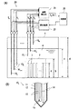
図1(A)は、各実施形態に係る液面レベル検知装置20が適用された使用済み燃料プール1を示している。
使用済み燃料プール1(以下「液体保持容器1」ともいう)には、複数の使用済み燃料集合体3を収納するラック2が配置されている。さらに、使用済み燃料プール1には、使用済み燃料集合体3の崩壊熱により昇温するプール水4を冷却する循環冷却器(図示略)が配置されている。
(First embodiment)
Hereinafter, embodiments of the present invention will be described with reference to the accompanying drawings.
FIG. 1A shows a
In the spent fuel pool 1 (hereinafter also referred to as “
そして、例えば、使用済み燃料集合体3の長さa=約4.5m、ラック2の高さb=約5mの場合、深さd=約12m程度の液体保持容器1が必要となり、基準水位c=約11mとなるようにプール水4の液面レベルが維持されている。
これにより、使用済み燃料集合体3から放出される高レベルの放射線は、プール水4に遮られ、液体保持容器1から外部漏洩することが抑制される。
液体保持容器1には、複数のプローブ10k[k=0〜n]が、その先端部分を高さ方向に間隔を空けて配置されている。
For example, when the length a of the
Thereby, the high level radiation emitted from the
In the
図1(B)に示すようにプローブ10kは、温度センサ12及びその検出点15の近傍に配置されるヒータ14を封入した封入管11で構成されている。
温度センサ12は、銅−コンスタンタン熱電対の素線13を、先端が閉じられているシース管に収容したものである。そして、この素線13とシース管の間には、絶縁材として酸化マグネシウムが充填されている。
検出点15において、銅の素線とコンスタンタンの素線とが溶接されている。そして、これら素線13の反対端は温度検出部21に導かれ、この反対端で検出される熱起電力に基づいて検出点15の周辺温度が計測される。
As shown in FIG. 1B, the
The
At the
液体保持容器1の深い位置におけるプール水4の液面レベルを検出するためには、熱電対の素線13を長い状態で施設する必要がある。しかし、この場合、熱電対の素線13に大きな負荷がかかるために、素線13そのものに優れた機械的特性が求められる。さらに、熱電対の素線13が長くなる程に、検出される熱起電力のノイズも大きくなるために、S/N比を稼ぐために熱起電力の大きな熱電対を採用する必要がある。
In order to detect the liquid level of the
銅−コンスタンタン熱電対の素線13は、一般的に使用されているクロメルアルメル熱電対と比較して、大きな熱起電力が得られ、低温測定に適する点において優れるが、機械的特性において劣る。そこで、温度センサ12としてシース式の銅−コンスタンタン熱電対を採用して、機械的強度を確保することとした。
The
このシース式の銅−コンスタンタンの温度センサ12は、引張加工前の銅−コンスタンタン熱電対の素線を、引張加工前のシース管に挿入した状態で、両者を同時に引張加工することにより製造される。シース管に収納されているため、銅−コンスタンタン熱電対の素線13に過剰な負荷が付与されることのない、長尺の温度センサ12を作成することができる。
This sheath-type copper-
封入管11は、内部に温度センサ12及びヒータ14を収容し、さらに熱伝導度の高い酸化マグネシウムで充填され、外側はプール水4(液相)や大気(気相)に接する。温度センサ12は、この封入管11及び酸化マグネシウムを介してプール水4(液相)や大気(気相)の温度を計測し、ヒータ14からの熱エネルギーは、この酸化マグネシウム及び封入管11を通過してプール水4(液相)や大気(気相)に放出される。
The enclosing
このように構成されるプローブ10kの温度センサ12からmVオーダーの電圧出力Vk[k=0〜n]が出力される。ヒータ14に電流を流して発生させたジュール熱は、プローブ10k[k=0〜n]の検出点15の周囲が気相であるか液相であるかによって熱拡散率が異なるために、温度センサ12の電圧出力Vkに違いを生じさせる。
The voltage output V k [k = 0 to n] in the mV order is output from the
温度検出部21は、プローブ10k[k=0〜n]から出力される微弱な電圧出力Vkをアナログ回路で処理可能な電圧レベルの温度信号VA(k)に変換して判定部30に出力する。具体的には、プローブ10kの測温範囲0〜100℃に対応する電圧出力Vkの電圧範囲を、1〜5Vの電圧範囲に対応させた温度信号VA(k)に変換する。
The
熱供給部22は、選定されたプローブ10k[k=0〜n]のヒータ14に通電してジュール熱を発生させ、検出点15の周辺に一定流量の熱エネルギーを供給する。なお、この熱供給の開始時点及び期間tは、判定部30から制御される。
The
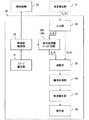
判定部30は、図2に示すように、温度センサ12(図1)の電圧出力Vkをアナログ量のまま温度信号VA(k)として入力する入力部33と、ヒータの熱供給に同期して温度信号VA(k)の処理信号VB(k)を出力する信号処理部34と、温度信号VA(k)及び処理信号VB(k)を演算処理して出力する演算部35と、この演算処理の出力結果に基づいて検出点15が気相又は液相のいずれに存在するかを識別する気液識別部37と、を備えている。
As shown in FIG. 2, the
プローブ選定部31は、液体保持容器1(図1)の気液識別を実施するプローブ10k[k=0〜n]を複数の中から選定する。
熱供給制御部32は、選定されたプローブ10kのヒータ14に対し一定流量の熱エネルギーを期間tだけ供給させるとともに、この熱供給の開始時点に同期して信号処理部34の処理を開始させる。
つまり、熱供給制御部32は、ヒータ通電をON/OFFさせる電圧信号を熱供給部22に出力して熱供給の期間tを規定するとともに、信号処理部34にも同レベルの電圧信号を出力する。
The
The heat
That is, the heat
入力部33は、入力した温度信号VA(k)をアナログ量のまま2つに分岐し、一方を演算部35に直接入力し、他方を信号処理部34に入力する。
信号処理部(ホールド回路)34Aは、熱供給制御部32からの同期信号を入力すると、この入力時点の温度信号VA(k)にホールドした処理信号VB(k)を出力する。
The
When the signal processing unit (hold circuit) 34A receives the synchronization signal from the heat
つまり、信号処理部34Aは、熱供給制御部32からの同期信号がOFF設定の時は、入力した温度信号VA(k)をそのまま出力する。そして、ON設定に切り替わった時、その時点で入力した温度信号VA(k)の入力電圧レベルが保持された処理信号VB(k)を、再びOFF設定に切り替わるまで出力し続ける。
このような信号処理部34Aは、例えばスイッチ接点とコンデンサを組み合わせたホールド回路などで構成される。
That is, the
Such a
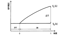
ここで図3のグラフは、プローブ10kの検出点15が気相に露出している場合に、熱供給制御部32の同期信号がOFF設定からON設定に切り替わった時の温度信号VA及びその処理信号VBの時間変化を示している。
このように、プローブ10kの先端が気相に露出している場合、ヒータ14から供給された熱エネルギーは、熱拡散率が小さい気相に拡散しないために、検出点15の周辺温度を大きく上昇させる。
このために、温度センサ12の温度信号VA(k)は、数分オーダーの時定数で上昇するとともに、ON切替時の温度信号VAに保持されている処理信号VBから大きく乖離する。
Here, the graph of FIG. 3 shows that when the
As described above, when the tip of the
For this reason, the temperature signal V A (k) of the
次に図4のグラフは、プローブ10kの検出点15が液相に浸漬している場合に、熱供給制御部32の同期信号がOFF設定からON設定に切り替わった時の温度信号VA及びその処理信号VBの時間変化を示している。
このように、プローブ10kの先端が液相に浸漬している場合、ヒータ14から供給された熱エネルギーは、熱拡散率が大きい液相に拡散するために、検出点15の周辺温度はあまり上昇しない。
このために、温度センサ12の温度信号VA(k)は、ON切替時の温度信号VAに保持されている処理信号VBからあまり乖離せずに平衡状態に達する。
Next, the graph of FIG. 4 shows that when the
As described above, when the tip of the
For this reason, the temperature signal V A (k) of the
演算部35(図2)は、温度信号VA(k)及びその処理信号VB(k)を互いに減算処理して閾値比較部36に出力する。
閾値比較部36は、熱供給の期間tにおいて演算部35の出力と閾値αとの関係が次の判定式(1)を満たすか否かについての判定信号を、気液識別部37に出力する。なお閾値αは、実験的に最適値が設定される。
α<VA(k)−VB(k) (1)
The computing unit 35 (FIG. 2) subtracts the temperature signal V A (k) and the processed signal V B (k) from each other and outputs the result to the
The
α <V A (k) −V B (k) (1)
そして気液識別部37は、この判定式(1)が充足されていればプローブ10kの先端は気相に露出していると識別し、非充足であればプローブ10kの先端は液相に浸漬していると識別する。
表示部38は、オペレータに対し、プローブ10kの先端部分が液相にあるか気相にあるかの識別結果を示すもので、例えばランプを点灯したり消灯したりする機能により実現される。
The gas-
The
また、他の動作例として演算部35(図2)は、温度信号VA(k)及びその処理信号VB(k)を互いに除算処理して閾値比較部36に出力する。
閾値比較部36は、熱供給の期間tにおいて演算部35の出力と閾値βとの関係が次の判定式(2)を満たすか否かについての判定信号を、気液識別部37に出力する。なお閾値βは、実験的に最適値が設定される。
β<VA(k)/VB(k) (2)
As another operation example, the calculation unit 35 (FIG. 2) divides the temperature signal V A (k) and the processing signal V B (k) from each other and outputs the result to the
The
β <V A (k) / V B (k) (2)
そして気液識別部37は、この判定式(2)が充足されていればプローブ10kの先端は気相に露出していると識別し、非充足であればプローブ10kの先端は液相に浸漬していると識別する。
The gas-
(第2実施形態)
次に図5を参照して本発明における第2実施形態について説明する。
第2実施形態では、判定部30において、信号処理部34B(34)が、温度信号の一次遅れ応答を出力する一次遅れ回路である点において、第1実施形態と相違する。なお、図5において図2と同一又は相当する部分は、同一符号で示し、重複する説明を省略する。
(Second Embodiment)
Next, a second embodiment of the present invention will be described with reference to FIG.
The second embodiment is different from the first embodiment in that the signal processing unit 34B (34) in the
このように、信号処理部34Bが、一次遅れ回路で構成されることにより、熱供給制御部32からの同期信号を必要とせずに、気液識別に利用する処理信号VB(k)を熱供給に同期して演算部35に出力することができる。
また、このような一次遅れ回路は、抵抗器とコンデンサのみで実現することができ、閾値比較部36は、熱供給の期間tの開始時点を認識する必要がないので、時間を意識することなく前記した判定式(1)又は(2)に基づく判定ができる。
このために、第2実施形態では、判定部30の構成を簡素化することができる。
As described above, since the signal processing unit 34B is configured by a first-order lag circuit, the processing signal V B (k) used for gas-liquid identification is not generated without the need for the synchronization signal from the heat
In addition, such a first-order lag circuit can be realized only with a resistor and a capacitor, and the
For this reason, in 2nd Embodiment, the structure of the
ここで図6のグラフは、第2実施形態におけるプローブ10kの検出点15が気相に露出している場合に、熱供給制御部32がOFF設定からON設定に切り替わった時の温度信号VA及びその処理信号VBの時間変化を示している。
Here, the graph of FIG. 6 shows the temperature signal V when the heat
熱供給制御部32がOFF設定である期間は、温度信号VA(k)が定常状態であるために、処理信号VBは温度信号VA(k)に収束している。
しかし、熱供給制御部32がON設定に切り替わると、気相からの温度信号VA(k)は大きく立ち上がって過渡状態に移行する。そして、この過渡状態の一次遅れ応答を示す処理信号VB(k)も、温度信号VA(k)に追従して増加するが、変化速度が付いていけず両者は大きく乖離することになる。
Since the temperature signal V A (k) is in a steady state during the period when the heat
However, when the heat
次に、図7のグラフは、第2実施形態におけるプローブ10kの検出点15が液相に浸漬している場合に、熱供給制御部32がOFF設定からON設定に切り替わった時の温度信号VA及びその処理信号VBの時間変化を示している。
Next, the graph of FIG. 7 shows the temperature signal when the heat
熱供給制御部32がOFF設定である期間において、温度信号VA(k)が定常状態であるために、この温度信号VA(k)に処理信号VBは収束している。
そして、熱供給制御部32がON設定に切り替わると、液相からの温度信号VA(k)は立ち上がって過渡状態に移行するが、その変化速度が小さい。このために、この過渡状態の一次遅れ応答を示す処理信号VB(k)は、温度信号VA(k)に追従して増加し、両者の乖離は小さい。なお、一次遅れの時定数は例として60秒程度とする。
Since the temperature signal V A (k) is in a steady state during the period when the heat
When the heat
図8のフローチャートに基づいて各実施形態に係る液面レベル検知装置の動作を説明する(適宜、図1参照)。
液体保持容器1の高さ方向に先端位置を変化させて配置されている複数のプローブ10k[k=0〜n]を上から順番に選定する(S11,S12)。そして、選定されたプローブ10kの温度センサ12の出力Vkをアナログ量のまま温度信号VA(k)として入力しつつヒータ14へ熱供給を開始する(S13,S14)。
The operation of the liquid level detection device according to each embodiment will be described based on the flowchart of FIG. 8 (see FIG. 1 as appropriate).
A plurality of probes 10 k [k = 0 to n] arranged by changing the tip position in the height direction of the
そして、この熱供給に同期して温度信号VA(k)の処理信号VB(k)(ホールド値又は一次遅れ応答)が出力され(S15)、熱供給の期間tが経過するまで温度信号VA(k)及びその処理信号VB(k)を演算処理して出力する(S16;No、Yes)。
そして演算処理の出力結果が、前記した判定式(1)又は判定式(2)を充足すれば気相と判定し(S17;Yes、S18)、未充足であれば液相と判定する(S17;No、S19)。
Then, a processing signal V B (k) (hold value or first-order lag response) of the temperature signal V A (k) is output in synchronization with this heat supply (S15), and the temperature signal is output until the heat supply period t elapses. V A (k) and its processed signal V B (k) are processed and output (S16; No, Yes).
If the output result of the arithmetic processing satisfies the above-described determination formula (1) or (2), it is determined as a gas phase (S17; Yes, S18), and if it is not satisfied, it is determined as a liquid phase (S17). No, S19).
さらに、次のプローブ10kに対して、気相/液相の判定を実施し(S20;No)、全てのプローブ10k[k=0〜n]における、気相/液相の判定結果から液体保持容器1の液面レベルを判定する(S20;Yes、S21)。
Further, the determination of the gas phase / liquid phase is performed for the next probe 10 k (S20; No), and the determination results of the gas phase / liquid phase in all the probes 10 k [k = 0 to n] are obtained. The liquid level of the
以上述べた少なくともひとつの実施形態の液面レベル検知装置によれば、アナログ回路のみで構成することができるために、原子力設備における不測の事態に対する強靭性が備わる。 According to the liquid level detection device of at least one embodiment described above, since it can be configured only by an analog circuit, it has toughness against unforeseen circumstances in nuclear facilities.
本発明のいくつかの実施形態を説明したが、これらの実施形態は、例として提示したものであり、発明の範囲を限定することは意図していない。これら実施形態は、その他の様々な形態で実施されることが可能であり、発明の要旨を逸脱しない範囲で、種々の省略、置き換え、変更、組み合わせを行うことができる。これら実施形態やその変形は、発明の範囲や要旨に含まれると同様に、特許請求の範囲に記載された発明とその均等の範囲に含まれるものである。 Although several embodiments of the present invention have been described, these embodiments are presented by way of example and are not intended to limit the scope of the invention. These embodiments can be implemented in various other forms, and various omissions, replacements, changes, and combinations can be made without departing from the scope of the invention. These embodiments and their modifications are included in the scope and gist of the invention, and are also included in the invention described in the claims and the equivalents thereof.
例えば、実施形態において、複数のプローブ10k[k=0〜n]を固定して、液面レベルを検知しているが、プローブを上下方向に移動させながら液面レベルを検知することもできる。 For example, in the embodiment, the plurality of probes 10 k [k = 0 to n] are fixed and the liquid level is detected, but the liquid level can also be detected while moving the probe in the vertical direction. .
1…使用済み燃料プール(液体保持容器)、2…ラック、3…使用済み燃料集合体、4…プール水、10k[k=0〜n]…プローブ、11…封入管、12…温度センサ、13…熱電対の素線、14…ヒータ、15…検出点、20…液面レベル検知装置、21…温度検出部、22…熱供給部、30…判定部、31…プローブ選定部、32…熱供給制御部、33…入力部、34(34A)…信号処理部(ホールド回路)、34(34B)…信号処理部(一次遅れ回路)、35…演算部、36…閾値比較部、37…気液識別部、38…表示部、Vk[k=0〜n]…温度センサの出力、VA(k)…温度信号、VB(k)…処理信号、t…熱供給の期間。 1 ... spent fuel pool (liquid holding vessel), 2 ... rack, 3 ... spent fuel assemblies, 4 ... pool water, 10 k [k = 0~n] ... probe, 11 ... sealed tube, 12 ... temperature sensor , 13 ... Thermocouple wire, 14 ... Heater, 15 ... Detection point, 20 ... Liquid level detection device, 21 ... Temperature detection unit, 22 ... Heat supply unit, 30 ... Determination unit, 31 ... Probe selection unit, 32 ... Heat supply control unit, 33 ... Input unit, 34 (34A) ... Signal processing unit (hold circuit), 34 (34B) ... Signal processing unit (primary delay circuit), 35 ... Calculation unit, 36 ... Threshold comparison unit, 37 ... liquid identification unit, 38 ... display unit, V k [k = 0~n] ... output of the temperature sensor, V a (k) ... temperature signal, V B (k) ... processed signal, period of t ... heat supply .
Claims (5)
前記複数のプローブの中から前記ヒータに通電するプローブを選定するプローブ選定部と、
前記プローブ選定部で選定した前記プローブの温度センサの出力をアナログ量のまま温度信号として入力する入力部と、
前記ヒータへの通電に同期して前記温度信号の処理信号を出力する信号処理部と、
前記温度信号及び前記処理信号を演算処理して結果を出力する演算部と、
前記演算処理の出力結果に基づいて前記検出点が気相又は液相のいずれに存在するかを識別する気液識別部と、
前記気液識別部の識別結果を示す表示部とを、備えることを特徴とする液面レベル検知装置。 A plurality of probes in which a temperature sensor and a heater arranged in the vicinity of the detection point are enclosed in the liquid holding container are arranged at regular intervals in the vertical direction of the liquid holding container, and based on the temperature signal from the probe A liquid level inspection apparatus for measuring a liquid level of a liquid holding container,
A probe selection unit for selecting a probe for energizing the heater from the plurality of probes;
An input unit for inputting the output of the temperature sensor of the probe selected by the probe selection unit as a temperature signal with an analog amount;
A signal processing unit that outputs a processing signal of the temperature signal in synchronization with energization of the heater;
An arithmetic unit that performs arithmetic processing on the temperature signal and the processing signal and outputs a result;
A gas-liquid identification unit that identifies whether the detection point exists in a gas phase or a liquid phase based on an output result of the arithmetic processing;
A liquid level detection apparatus comprising: a display unit that indicates an identification result of the gas-liquid identification unit.
前記気液識別部の識別結果に基づいて前記液面レベルを判定する液面レベル判定部を、さらに備えることを特徴とする液面レベル検査装置。 In the liquid level detection apparatus according to claim 1,
The liquid level inspection apparatus further comprising a liquid level determination unit that determines the liquid level based on the identification result of the gas-liquid identification unit.
前記演算部は、前記温度信号及び前記処理信号を互いに減算するか又は除算した結果を出力することを特徴とする液面レベル検知装置。 In the liquid level detection apparatus according to claim 1 or 2,
The liquid level detector according to claim 1, wherein the arithmetic unit outputs a result obtained by subtracting or dividing the temperature signal and the processing signal.
前記信号処理部は、前記通電の開始時点の前記温度信号にホールドするホールド回路であるか、又は前記温度信号の一次遅れ応答を出力する一次遅れ回路であることを特徴とする液面レベル検知装置。 In the liquid level detection apparatus according to any one of claims 1 to 3,
The liquid level detector according to claim 1, wherein the signal processing unit is a hold circuit that holds the temperature signal at a start time of the energization, or a primary delay circuit that outputs a first-order delay response of the temperature signal. .
前記複数のプローブの中から前記ヒータに通電するプローブを選定するステップと、
前記選定された前記プローブの温度センサの出力をアナログ量のまま温度信号として入力するステップと、
前記ヒータへの通電に同期して前記温度信号の処理信号を出力するステップと、
前記温度信号及び前記処理信号を演算処理して結果を出力するステップと、
前記演算処理の出力結果に基づいて前記検出点が気相又は液相のいずれに存在するかを識別するステップと、
選定された前記プローブの少なくとも一つに基づく前記識別結果を表示するステップとを、含むことを特徴とする液面レベル検知方法。 A plurality of probes in which a temperature sensor and a heater arranged in the vicinity of the detection point are enclosed in the liquid holding container are arranged at regular intervals in the vertical direction of the liquid holding container, and based on the temperature signal from the probe A liquid level inspection method for measuring a liquid level of a liquid holding container,
Selecting a probe to energize the heater from the plurality of probes;
Inputting an output of a temperature sensor of the selected probe as a temperature signal in an analog amount;
Outputting a processing signal of the temperature signal in synchronization with energization of the heater;
Computing the temperature signal and the processed signal and outputting a result;
Identifying whether the detection point exists in a gas phase or a liquid phase based on an output result of the arithmetic processing;
And displaying the identification results based on at least one of the selected said probe, liquid level detection method, which comprises.
Priority Applications (4)
| Application Number | Priority Date | Filing Date | Title |
|---|---|---|---|
| JP2012014554A JP5583153B2 (en) | 2012-01-26 | 2012-01-26 | Liquid level detection device and method |
| EP13741506.3A EP2808658A4 (en) | 2012-01-26 | 2013-01-25 | Liquid level detection device and method |
| PCT/JP2013/051560 WO2013111847A1 (en) | 2012-01-26 | 2013-01-25 | Liquid level detection device and method |
| US14/374,272 US9423286B2 (en) | 2012-01-26 | 2013-01-25 | Liquid level sensing apparatus and method |
Applications Claiming Priority (1)
| Application Number | Priority Date | Filing Date | Title |
|---|---|---|---|
| JP2012014554A JP5583153B2 (en) | 2012-01-26 | 2012-01-26 | Liquid level detection device and method |
Publications (3)
| Publication Number | Publication Date |
|---|---|
| JP2013156036A JP2013156036A (en) | 2013-08-15 |
| JP2013156036A5 JP2013156036A5 (en) | 2014-04-17 |
| JP5583153B2 true JP5583153B2 (en) | 2014-09-03 |
Family
ID=48873559
Family Applications (1)
| Application Number | Title | Priority Date | Filing Date |
|---|---|---|---|
| JP2012014554A Active JP5583153B2 (en) | 2012-01-26 | 2012-01-26 | Liquid level detection device and method |
Country Status (4)
| Country | Link |
|---|---|
| US (1) | US9423286B2 (en) |
| EP (1) | EP2808658A4 (en) |
| JP (1) | JP5583153B2 (en) |
| WO (1) | WO2013111847A1 (en) |
Families Citing this family (11)
| Publication number | Priority date | Publication date | Assignee | Title |
|---|---|---|---|---|
| US20140072086A1 (en) * | 2012-09-11 | 2014-03-13 | Ge-Hitachi Nuclear Energy Americas Llc | Method and system for measuring a spent fuel pool temperature and liquid level without external electrical power |
| US11017907B2 (en) | 2013-12-31 | 2021-05-25 | Nuscale Power, Llc | Nuclear reactor protection systems and methods |
| US20150323938A1 (en) * | 2014-05-09 | 2015-11-12 | Honeywell International Inc. | Temperature-based level detection and control method and apparatus |
| JP6401584B2 (en) * | 2014-11-25 | 2018-10-10 | 住友精密工業株式会社 | Liquid level detection device and liquid level detection system |
| JP6653161B2 (en) * | 2015-11-10 | 2020-02-26 | 日立Geニュークリア・エナジー株式会社 | Water level measurement system |
| EP3563391B1 (en) * | 2016-12-30 | 2023-07-05 | NuScale Power, LLC | Nuclear reactor protection systems and methods |
| JP6752169B2 (en) * | 2017-03-14 | 2020-09-09 | 日立Geニュークリア・エナジー株式会社 | Thermocouple liquid level measurement system |
| RU175490U1 (en) * | 2017-05-15 | 2017-12-06 | Общество с ограниченной ответственностью Научно-производственное объединение (ООО НПО "ИНКОР") | TEMPERATURE AND LIQUID CONTROL PROBE |
| US10760937B2 (en) * | 2017-09-08 | 2020-09-01 | RV Whisper LLC | System and method for measuring the level of fluid in a container |
| EP4053516A1 (en) * | 2021-03-05 | 2022-09-07 | HORIBA STEC, Co., Ltd. | Material supply system, program for a material supply system and material supply method |
| CN113280887A (en) * | 2021-05-14 | 2021-08-20 | 山西天泽煤化工集团股份公司 | Special algorithm liquid level meter |
Family Cites Families (42)
| Publication number | Priority date | Publication date | Assignee | Title |
|---|---|---|---|---|
| US2246563A (en) * | 1940-06-13 | 1941-06-24 | Universal Oil Prod Co | Liquid level indication and control |
| US3280627A (en) * | 1963-05-27 | 1966-10-25 | American Radiator & Standard | Liquid level sensor |
| US3905243A (en) * | 1973-09-11 | 1975-09-16 | Us Energy | Liquid-level sensing device |
| US4016758A (en) * | 1975-09-09 | 1977-04-12 | Taylor Julian S | Thermal gauge probe |
| JPS5593025A (en) * | 1979-01-08 | 1980-07-15 | Mitsubishi Electric Corp | Superconductive liquid level indicator |
| JPS5673320A (en) * | 1979-11-20 | 1981-06-18 | Toshiba Corp | Water level detecting device |
| JPS5676014A (en) * | 1979-11-28 | 1981-06-23 | Hitachi Ltd | Measuring device for liquid level at extreme low temperature |
| JPS56114718A (en) * | 1980-02-14 | 1981-09-09 | Toshiba Corp | Liquid level indicator |
| DE3022398A1 (en) * | 1980-06-14 | 1982-01-07 | Vdo Adolf Schindling Ag, 6000 Frankfurt | DEVICE FOR ELECTRICALLY MONITORING THE LEVEL OF A LIQUID CONTAINED IN A CONTAINER |
| US4356480A (en) * | 1980-09-11 | 1982-10-26 | Minnesota Mining And Manufacturing Company | Liquid level sensing circuitry |
| JPS5764115A (en) * | 1980-10-07 | 1982-04-19 | Japan Atom Energy Res Inst | Method and apparatus detecting liquid level |
| US4367462A (en) * | 1981-01-05 | 1983-01-04 | Minnesota Mining And Manufacturing Company | Liquid level sensing circuitry |
| DE3148383A1 (en) * | 1981-12-07 | 1983-06-16 | Siemens AG, 1000 Berlin und 8000 München | Device for measuring the filling level |
| JPS59107213A (en) * | 1982-12-10 | 1984-06-21 | Mitsubishi Electric Corp | Detector for liquid level |
| DE3408824A1 (en) * | 1984-03-10 | 1985-09-12 | Vdo Adolf Schindling Ag, 6000 Frankfurt | CIRCUIT ARRANGEMENT FOR ELECTROTHERMIC, AMBIENT TEMPERATURE COMPENSATED LEVEL MEASUREMENT |
| DE3423802A1 (en) * | 1984-06-28 | 1986-01-02 | Vdo Adolf Schindling Ag, 6000 Frankfurt | METHOD AND DEVICE FOR ELECTROTHERMIC, AMBIENT TEMPERATURE COMPENSATED LEVEL MEASUREMENT |
| JPS6176913A (en) * | 1984-09-25 | 1986-04-19 | Hitachi Ltd | Thermocouple type liquid-level meter |
| US4609913A (en) * | 1985-02-22 | 1986-09-02 | Wickes Manufacturing Company | Fluid level sensor |
| JPH0535293Y2 (en) * | 1988-03-18 | 1993-09-08 | ||
| US4929930A (en) * | 1988-10-24 | 1990-05-29 | Process Technology Inc. | Liquid level controller utilizing the rate of change of a thermocouple |
| US5111692A (en) * | 1990-03-27 | 1992-05-12 | Fluid Components, Inc. | Temperature compensated liquid level and fluid flow sensor |
| US5211904A (en) * | 1990-12-10 | 1993-05-18 | General Electric Company | In-vessel water level monitor for boiling water reactors |
| US5209115A (en) * | 1991-09-11 | 1993-05-11 | Intelsat | Liquid detector for thin-walled tanks operating in zero gravity |
| JPH05107099A (en) * | 1991-10-18 | 1993-04-27 | Chichibu Cement Co Ltd | Liquid level meter |
| JPH078729U (en) * | 1993-07-20 | 1995-02-07 | 清彦 三嘴 | Water level sensor |
| DE4434559C2 (en) * | 1994-09-28 | 1999-09-02 | Mannesmann Vdo Ag | Method and arrangement for operating a level sensor |
| US5730026A (en) * | 1995-03-31 | 1998-03-24 | Josef Maatuk | Microprocessor-based liquid sensor and ice detector |
| US5782131A (en) * | 1996-06-28 | 1998-07-21 | Lord; Richard G. | Flooded cooler with liquid level sensor |
| JPH10153681A (en) | 1996-11-22 | 1998-06-09 | Mitsubishi Heavy Ind Ltd | Water level measuring device for pressure suppression pool |
| JPH10332458A (en) * | 1997-05-27 | 1998-12-18 | Furukawa Electric Co Ltd:The | Cryogenic refrigerant liquid level gage |
| US6615658B2 (en) * | 1999-08-03 | 2003-09-09 | Charles Darwin Snelling | Method and apparatus for detecting the internal liquid level in a vessel |
| JP2002214020A (en) * | 2001-01-15 | 2002-07-31 | Erumekku Denshi Kogyo Kk | Liquid level measuring apparatus |
| US6536276B2 (en) * | 2001-02-27 | 2003-03-25 | Rosemont Aerospace Inc. | Apparatus and method to non-intrusively measure the level of liquid in a sealed container |
| US6546796B2 (en) * | 2001-03-15 | 2003-04-15 | Therm-O-Disc, Incorporated | Liquid level sensor |
| AUPR689601A0 (en) * | 2001-08-08 | 2001-08-30 | Refrigerant Monitoring Systems Pty Ltd | Liquid level sensor |
| JP2005134230A (en) * | 2003-10-30 | 2005-05-26 | Fuji Electric Retail Systems Co Ltd | Liquid level detection device |
| US20050126282A1 (en) * | 2003-12-16 | 2005-06-16 | Josef Maatuk | Liquid sensor and ice detector |
| US20100294021A1 (en) * | 2006-03-28 | 2010-11-25 | Mitsui Mining & Smelting Co., Ltd. | Fluid Identification Device and Fluid Identification Method |
| US7828960B1 (en) * | 2007-05-16 | 2010-11-09 | Thermaco, Inc. | F.O.G. separator control |
| JP5865614B2 (en) * | 2011-06-27 | 2016-02-17 | 株式会社東芝 | Water level detector for nuclear power plant |
| WO2013003891A1 (en) * | 2011-07-01 | 2013-01-10 | Breville Pty Limited | Method and apparatus for water level sensing |
| US9091583B2 (en) * | 2012-11-16 | 2015-07-28 | Amphenol Thermometrics, Inc. | Fluid level sensor system and method |
-
2012
- 2012-01-26 JP JP2012014554A patent/JP5583153B2/en active Active
-
2013
- 2013-01-25 EP EP13741506.3A patent/EP2808658A4/en not_active Withdrawn
- 2013-01-25 WO PCT/JP2013/051560 patent/WO2013111847A1/en active Application Filing
- 2013-01-25 US US14/374,272 patent/US9423286B2/en not_active Expired - Fee Related
Also Published As
| Publication number | Publication date |
|---|---|
| WO2013111847A1 (en) | 2013-08-01 |
| EP2808658A1 (en) | 2014-12-03 |
| EP2808658A4 (en) | 2015-12-23 |
| JP2013156036A (en) | 2013-08-15 |
| US20150040660A1 (en) | 2015-02-12 |
| US9423286B2 (en) | 2016-08-23 |
Similar Documents
| Publication | Publication Date | Title |
|---|---|---|
| JP5583153B2 (en) | Liquid level detection device and method | |
| US20130177122A1 (en) | Reactor Water-Level/Temperature Measurement Apparatus | |
| JP5787729B2 (en) | Water level temperature measuring device | |
| JP5826605B2 (en) | Apparatus and method for detecting water level in spent fuel storage pool | |
| EP0066516B1 (en) | Device for checking the coolant condition in a nuclear reactor | |
| JP6529401B2 (en) | Apparatus, method and program for detecting gas leakage of radioactive substance sealed container | |
| JP5865614B2 (en) | Water level detector for nuclear power plant | |
| JP2013108905A (en) | Reactor water level instrumentation system | |
| US20160069728A1 (en) | Robust Dynamical Method and Device for Detecting the Level of a Liquid Using Resistance Temperature Detectors | |
| US20090234596A1 (en) | Apparatus for detecting position of liquid surface and determining liquid volume | |
| TWI657232B (en) | Liquid level meter, gasifier with the same and liquid level detection method | |
| JP6819784B2 (en) | Temperature measuring device, temperature measuring method and temperature measuring program | |
| JP2007078559A (en) | Device and method for measuring temperature of core coolant, and reactor monitor | |
| US4781469A (en) | Detecting proximity or occurrence of change of phase within a fluid | |
| JP6382609B2 (en) | Liquid level measurement system and method | |
| JP6383276B2 (en) | Water level measuring device, water level measuring method, and nuclear power plant | |
| JP3028941B2 (en) | Multi-sheath type sodium leak detection device | |
| JP2013113808A (en) | Liquid level measuring device, method and program | |
| US20240044723A1 (en) | Noninvasive thermometer | |
| JP5815100B2 (en) | Reactor water level measurement system | |
| JP6025359B2 (en) | Water level gauge and nuclear facility | |
| JP6637738B2 (en) | Reactor water level estimation device | |
| JPS5926025A (en) | Temperature difference measuring device of lng storage tank | |
| JP6896586B2 (en) | Reactor water level gauge | |
| JP2018025503A (en) | Liquid level measurement device, liquid level measurement evaluation method |
Legal Events
| Date | Code | Title | Description |
|---|---|---|---|
| A521 | Written amendment |
Free format text: JAPANESE INTERMEDIATE CODE: A523 Effective date: 20140227 |
|
| A621 | Written request for application examination |
Free format text: JAPANESE INTERMEDIATE CODE: A621 Effective date: 20140227 |
|
| A871 | Explanation of circumstances concerning accelerated examination |
Free format text: JAPANESE INTERMEDIATE CODE: A871 Effective date: 20140227 |
|
| A975 | Report on accelerated examination |
Free format text: JAPANESE INTERMEDIATE CODE: A971005 Effective date: 20140318 |
|
| A131 | Notification of reasons for refusal |
Free format text: JAPANESE INTERMEDIATE CODE: A131 Effective date: 20140513 |
|
| A521 | Written amendment |
Free format text: JAPANESE INTERMEDIATE CODE: A523 Effective date: 20140602 |
|
| TRDD | Decision of grant or rejection written | ||
| A01 | Written decision to grant a patent or to grant a registration (utility model) |
Free format text: JAPANESE INTERMEDIATE CODE: A01 Effective date: 20140617 |
|
| A61 | First payment of annual fees (during grant procedure) |
Free format text: JAPANESE INTERMEDIATE CODE: A61 Effective date: 20140715 |
|
| R151 | Written notification of patent or utility model registration |
Ref document number: 5583153 Country of ref document: JP Free format text: JAPANESE INTERMEDIATE CODE: R151 |