JP5582397B2 - Electric tool and battery pack used for electric tool - Google Patents
Electric tool and battery pack used for electric tool Download PDFInfo
- Publication number
- JP5582397B2 JP5582397B2 JP2010195200A JP2010195200A JP5582397B2 JP 5582397 B2 JP5582397 B2 JP 5582397B2 JP 2010195200 A JP2010195200 A JP 2010195200A JP 2010195200 A JP2010195200 A JP 2010195200A JP 5582397 B2 JP5582397 B2 JP 5582397B2
- Authority
- JP
- Japan
- Prior art keywords
- current
- switching element
- battery pack
- battery
- time
- Prior art date
- Legal status (The legal status is an assumption and is not a legal conclusion. Google has not performed a legal analysis and makes no representation as to the accuracy of the status listed.)
- Expired - Fee Related
Links
Images


Classifications
-
- B—PERFORMING OPERATIONS; TRANSPORTING
- B25—HAND TOOLS; PORTABLE POWER-DRIVEN TOOLS; MANIPULATORS
- B25F—COMBINATION OR MULTI-PURPOSE TOOLS NOT OTHERWISE PROVIDED FOR; DETAILS OR COMPONENTS OF PORTABLE POWER-DRIVEN TOOLS NOT PARTICULARLY RELATED TO THE OPERATIONS PERFORMED AND NOT OTHERWISE PROVIDED FOR
- B25F5/00—Details or components of portable power-driven tools not particularly related to the operations performed and not otherwise provided for
-
- B—PERFORMING OPERATIONS; TRANSPORTING
- B23—MACHINE TOOLS; METAL-WORKING NOT OTHERWISE PROVIDED FOR
- B23Q—DETAILS, COMPONENTS, OR ACCESSORIES FOR MACHINE TOOLS, e.g. ARRANGEMENTS FOR COPYING OR CONTROLLING; MACHINE TOOLS IN GENERAL CHARACTERISED BY THE CONSTRUCTION OF PARTICULAR DETAILS OR COMPONENTS; COMBINATIONS OR ASSOCIATIONS OF METAL-WORKING MACHINES, NOT DIRECTED TO A PARTICULAR RESULT
- B23Q17/00—Arrangements for observing, indicating or measuring on machine tools
- B23Q17/007—Arrangements for observing, indicating or measuring on machine tools for managing machine functions not concerning the tool
-
- H—ELECTRICITY
- H01—ELECTRIC ELEMENTS
- H01M—PROCESSES OR MEANS, e.g. BATTERIES, FOR THE DIRECT CONVERSION OF CHEMICAL ENERGY INTO ELECTRICAL ENERGY
- H01M10/00—Secondary cells; Manufacture thereof
- H01M10/42—Methods or arrangements for servicing or maintenance of secondary cells or secondary half-cells
- H01M10/4207—Methods or arrangements for servicing or maintenance of secondary cells or secondary half-cells for several batteries or cells simultaneously or sequentially
-
- H—ELECTRICITY
- H01—ELECTRIC ELEMENTS
- H01M—PROCESSES OR MEANS, e.g. BATTERIES, FOR THE DIRECT CONVERSION OF CHEMICAL ENERGY INTO ELECTRICAL ENERGY
- H01M10/00—Secondary cells; Manufacture thereof
- H01M10/42—Methods or arrangements for servicing or maintenance of secondary cells or secondary half-cells
- H01M10/425—Structural combination with electronic components, e.g. electronic circuits integrated to the outside of the casing
-
- H—ELECTRICITY
- H01—ELECTRIC ELEMENTS
- H01M—PROCESSES OR MEANS, e.g. BATTERIES, FOR THE DIRECT CONVERSION OF CHEMICAL ENERGY INTO ELECTRICAL ENERGY
- H01M10/00—Secondary cells; Manufacture thereof
- H01M10/42—Methods or arrangements for servicing or maintenance of secondary cells or secondary half-cells
- H01M10/44—Methods for charging or discharging
- H01M10/441—Methods for charging or discharging for several batteries or cells simultaneously or sequentially
-
- H—ELECTRICITY
- H01—ELECTRIC ELEMENTS
- H01M—PROCESSES OR MEANS, e.g. BATTERIES, FOR THE DIRECT CONVERSION OF CHEMICAL ENERGY INTO ELECTRICAL ENERGY
- H01M50/00—Constructional details or processes of manufacture of the non-active parts of electrochemical cells other than fuel cells, e.g. hybrid cells
- H01M50/20—Mountings; Secondary casings or frames; Racks, modules or packs; Suspension devices; Shock absorbers; Transport or carrying devices; Holders
- H01M50/204—Racks, modules or packs for multiple batteries or multiple cells
- H01M50/207—Racks, modules or packs for multiple batteries or multiple cells characterised by their shape
- H01M50/213—Racks, modules or packs for multiple batteries or multiple cells characterised by their shape adapted for cells having curved cross-section, e.g. round or elliptic
-
- H—ELECTRICITY
- H02—GENERATION; CONVERSION OR DISTRIBUTION OF ELECTRIC POWER
- H02J—CIRCUIT ARRANGEMENTS OR SYSTEMS FOR SUPPLYING OR DISTRIBUTING ELECTRIC POWER; SYSTEMS FOR STORING ELECTRIC ENERGY
- H02J7/00—Circuit arrangements for charging or depolarising batteries or for supplying loads from batteries
- H02J7/0029—Circuit arrangements for charging or depolarising batteries or for supplying loads from batteries with safety or protection devices or circuits
- H02J7/00304—Overcurrent protection
-
- H—ELECTRICITY
- H02—GENERATION; CONVERSION OR DISTRIBUTION OF ELECTRIC POWER
- H02J—CIRCUIT ARRANGEMENTS OR SYSTEMS FOR SUPPLYING OR DISTRIBUTING ELECTRIC POWER; SYSTEMS FOR STORING ELECTRIC ENERGY
- H02J7/00—Circuit arrangements for charging or depolarising batteries or for supplying loads from batteries
- H02J7/0029—Circuit arrangements for charging or depolarising batteries or for supplying loads from batteries with safety or protection devices or circuits
- H02J7/0031—Circuit arrangements for charging or depolarising batteries or for supplying loads from batteries with safety or protection devices or circuits using battery or load disconnect circuits
-
- H—ELECTRICITY
- H02—GENERATION; CONVERSION OR DISTRIBUTION OF ELECTRIC POWER
- H02J—CIRCUIT ARRANGEMENTS OR SYSTEMS FOR SUPPLYING OR DISTRIBUTING ELECTRIC POWER; SYSTEMS FOR STORING ELECTRIC ENERGY
- H02J7/00—Circuit arrangements for charging or depolarising batteries or for supplying loads from batteries
- H02J7/0063—Circuit arrangements for charging or depolarising batteries or for supplying loads from batteries with circuits adapted for supplying loads from the battery
-
- H—ELECTRICITY
- H02—GENERATION; CONVERSION OR DISTRIBUTION OF ELECTRIC POWER
- H02J—CIRCUIT ARRANGEMENTS OR SYSTEMS FOR SUPPLYING OR DISTRIBUTING ELECTRIC POWER; SYSTEMS FOR STORING ELECTRIC ENERGY
- H02J7/00—Circuit arrangements for charging or depolarising batteries or for supplying loads from batteries
- H02J7/007—Regulation of charging or discharging current or voltage
- H02J7/00712—Regulation of charging or discharging current or voltage the cycle being controlled or terminated in response to electric parameters
- H02J7/00714—Regulation of charging or discharging current or voltage the cycle being controlled or terminated in response to electric parameters in response to battery charging or discharging current
-
- H—ELECTRICITY
- H01—ELECTRIC ELEMENTS
- H01M—PROCESSES OR MEANS, e.g. BATTERIES, FOR THE DIRECT CONVERSION OF CHEMICAL ENERGY INTO ELECTRICAL ENERGY
- H01M10/00—Secondary cells; Manufacture thereof
- H01M10/05—Accumulators with non-aqueous electrolyte
- H01M10/052—Li-accumulators
-
- H—ELECTRICITY
- H01—ELECTRIC ELEMENTS
- H01M—PROCESSES OR MEANS, e.g. BATTERIES, FOR THE DIRECT CONVERSION OF CHEMICAL ENERGY INTO ELECTRICAL ENERGY
- H01M2220/00—Batteries for particular applications
- H01M2220/30—Batteries in portable systems, e.g. mobile phone, laptop
-
- H—ELECTRICITY
- H02—GENERATION; CONVERSION OR DISTRIBUTION OF ELECTRIC POWER
- H02J—CIRCUIT ARRANGEMENTS OR SYSTEMS FOR SUPPLYING OR DISTRIBUTING ELECTRIC POWER; SYSTEMS FOR STORING ELECTRIC ENERGY
- H02J7/00—Circuit arrangements for charging or depolarising batteries or for supplying loads from batteries
- H02J7/0029—Circuit arrangements for charging or depolarising batteries or for supplying loads from batteries with safety or protection devices or circuits
- H02J7/00302—Overcharge protection
-
- H—ELECTRICITY
- H02—GENERATION; CONVERSION OR DISTRIBUTION OF ELECTRIC POWER
- H02J—CIRCUIT ARRANGEMENTS OR SYSTEMS FOR SUPPLYING OR DISTRIBUTING ELECTRIC POWER; SYSTEMS FOR STORING ELECTRIC ENERGY
- H02J7/00—Circuit arrangements for charging or depolarising batteries or for supplying loads from batteries
- H02J7/0029—Circuit arrangements for charging or depolarising batteries or for supplying loads from batteries with safety or protection devices or circuits
- H02J7/00306—Overdischarge protection
-
- H—ELECTRICITY
- H02—GENERATION; CONVERSION OR DISTRIBUTION OF ELECTRIC POWER
- H02J—CIRCUIT ARRANGEMENTS OR SYSTEMS FOR SUPPLYING OR DISTRIBUTING ELECTRIC POWER; SYSTEMS FOR STORING ELECTRIC ENERGY
- H02J7/00—Circuit arrangements for charging or depolarising batteries or for supplying loads from batteries
- H02J7/007—Regulation of charging or discharging current or voltage
- H02J7/00711—Regulation of charging or discharging current or voltage with introduction of pulses during the charging process
-
- Y—GENERAL TAGGING OF NEW TECHNOLOGICAL DEVELOPMENTS; GENERAL TAGGING OF CROSS-SECTIONAL TECHNOLOGIES SPANNING OVER SEVERAL SECTIONS OF THE IPC; TECHNICAL SUBJECTS COVERED BY FORMER USPC CROSS-REFERENCE ART COLLECTIONS [XRACs] AND DIGESTS
- Y02—TECHNOLOGIES OR APPLICATIONS FOR MITIGATION OR ADAPTATION AGAINST CLIMATE CHANGE
- Y02E—REDUCTION OF GREENHOUSE GAS [GHG] EMISSIONS, RELATED TO ENERGY GENERATION, TRANSMISSION OR DISTRIBUTION
- Y02E60/00—Enabling technologies; Technologies with a potential or indirect contribution to GHG emissions mitigation
- Y02E60/10—Energy storage using batteries
Landscapes
- Engineering & Computer Science (AREA)
- Chemical & Material Sciences (AREA)
- Chemical Kinetics & Catalysis (AREA)
- Electrochemistry (AREA)
- General Chemical & Material Sciences (AREA)
- Power Engineering (AREA)
- Manufacturing & Machinery (AREA)
- Mechanical Engineering (AREA)
- Microelectronics & Electronic Packaging (AREA)
- Secondary Cells (AREA)
- Charge And Discharge Circuits For Batteries Or The Like (AREA)
- Battery Mounting, Suspending (AREA)
- Portable Power Tools In General (AREA)
- Protection Of Static Devices (AREA)
Description
本発明はリチウムイオン電池等を用いたコードレス式の電動工具に関し、特に比較的大電流が、数秒から数十秒ほど持続する過電流状態からの保護回路を備えたコードレス式の電動工具及び電動工具に用いられる電池パックに関する。 The present invention relates to a cordless power tool using a lithium ion battery or the like, and in particular, a cordless power tool and a power tool provided with a protection circuit from an overcurrent state in which a relatively large current lasts for several seconds to several tens of seconds. The present invention relates to a battery pack used for the above.
電動ドライバ、電動ドリル、インパクト工具などの電動工具は一般に、モータによる回転動力を減速機構により減速した後、先端工具にモータの動力を伝達する。モータの電源としては従来、交流の商用電源が用いられてきたが、近年、ニッケル水素電池やリチウムイオン電池等に代表される二次電池を電源として用いたコードレス電動工具が多用されるようになった。特に、リチウムイオン電池、リチウムイオンポリマー電池に代表されるリチウムイオン二次電池は、公称電圧が大きいために必要とする電池セル数を少なくすることができ、この結果、電動工具を軽量小型にできるという利点がある。ここでリチウムイオン二次電池とは、非水電解質二次電池の一種で、電解質中のリチウムイオンが電気伝導を担う二次電池である。リチウムイオン電池は一般に、正極にコバルト酸リチウム、負極に黒鉛を使用し、電解液として有機電解液を用いたものである。 In general, electric tools such as an electric driver, an electric drill, and an impact tool transmit the power of the motor to the tip tool after the rotational power of the motor is reduced by a reduction mechanism. Conventionally, an AC commercial power source has been used as a power source for a motor. However, in recent years, cordless electric tools using a secondary battery represented by a nickel hydride battery or a lithium ion battery as a power source have come to be used frequently. It was. In particular, lithium ion secondary batteries represented by lithium ion batteries and lithium ion polymer batteries can reduce the number of battery cells required because the nominal voltage is large, and as a result, the power tool can be reduced in size and weight. There is an advantage. Here, the lithium ion secondary battery is a kind of non-aqueous electrolyte secondary battery, and is a secondary battery in which lithium ions in the electrolyte bear electric conduction. Lithium ion batteries generally use lithium cobaltate for the positive electrode, graphite for the negative electrode, and an organic electrolyte as the electrolyte.
リチウムイオン二次電池の公称電圧は、例えば3.6Vと高く、ニッケル水素電池の3本分に相当する電圧が得られるから、電動工具の電源として用いた場合はニッケル水素電池に比べて電池セル本数を大幅に低減することができるという利点がある。その反面、リチウムイオン二次電池は過充電、過放電を行ったり、過大な電流を流すとサイクル寿命が著しく劣化する恐れがある。 The nominal voltage of a lithium ion secondary battery is as high as 3.6 V, for example, and a voltage equivalent to three nickel metal hydride batteries can be obtained. Therefore, when used as a power source for a power tool, a battery cell compared to a nickel metal hydride battery There is an advantage that the number can be greatly reduced. On the other hand, if the lithium ion secondary battery is overcharged, overdischarged or an excessive current is passed, the cycle life may be significantly deteriorated.
過電流を防ぐために本出願人は特許文献1において、モータの始動時に流れる瞬時の過大電流は許容し、電動工具の使用時に生じるモータのロック時の過大電流は遮断し得る保護回路を備えた電池パックを提案した。また、特許文献2において、過電流や過放電が生じた際に電流の流れを遮断する遮断手段を、必要な個数だけ電動工具側に設けるように構成した。
In order to prevent overcurrent, the applicant of
電動工具において、過大電流に対するモータの保護を行うことが重要であるが、一方で所定の大電流(或いは中電流)が所定時間以上流れ続けることによる電池の劣化を防ぐことも重要であることがわかってきた。例えば図15に示すようなモータ及び電池を含む回路において、直流電源たる電池VからスイッチSを介して直流モータMに直流電圧を印加した場合、スイッチSを閉成した直後、つまり始動時には直流モータM及びスイッチSに次式(1)で表わされる電流Iaが流れる。
Ia=(V−E)/Ra・・・(1)
但しVは直流電源Vの電圧、Raは直流モータMの電機子巻線の抵抗値、Eは直流モータの逆起電力である。
In power tools, it is important to protect the motor against excessive current, but it is also important to prevent battery deterioration due to a predetermined large current (or medium current) flowing for a predetermined time or longer. I understand. For example, in a circuit including a motor and a battery as shown in FIG. 15, when a DC voltage is applied from a battery V as a DC power source to a DC motor M via a switch S, the DC motor is immediately after the switch S is closed, that is, at the time of starting. A current Ia represented by the following expression (1) flows through M and the switch S.
Ia = (VE) / Ra (1)
Where V is the voltage of the DC power supply V, Ra is the resistance value of the armature winding of the DC motor M, and E is the counter electromotive force of the DC motor.
直流モータMの始動時は回転子が静止した状態であるため逆起電力Eは0となり過大な電流が非常に短時間流れるのは避け難い。一方、電動ドライバ、電動ドリル等の電動工具では、先端工具が被加工物に食い込んだり噛み付いたりすることがあり、その場合にも直流モータMは一時的にロック状態となることがある。モータがロック状態になったときは、直流モータMの逆起電力Eは0になるため、回路には過大な電流が流れることになる。 Since the rotor is stationary when the DC motor M is started, the back electromotive force E becomes 0 and it is difficult to avoid excessive current flowing for a very short time. On the other hand, in an electric tool such as an electric screwdriver or an electric drill, the tip tool may bite into or bite the workpiece, and in this case, the DC motor M may be temporarily locked. When the motor is locked, the counter electromotive force E of the DC motor M becomes 0, so that an excessive current flows in the circuit.
また、丸のこ、ハンマドリル、ジグソーなどのコードレス式の電動工具においては、モータがロック状態になることは少ないものの、作業者の電動工具への押圧具合によっては、モータに高い負荷が掛かりモータの回転数が下がって逆起電力Eが低下するため、モータに多大な電流が流れ続ける恐れがある。このようにモータに多大な電流が流れ続けることは、電池から大電力の放電が続くことになり、電池の過放電や、長い時間の大電流によるサイクル寿命低下が懸念される状態となる。 Also, in cordless power tools such as circular saws, hammer drills, jigsaws, etc., the motor is unlikely to be locked, but depending on how the operator presses against the power tool, a high load is applied to the motor and the motor Since the number of rotations decreases and the back electromotive force E decreases, a large current may continue to flow through the motor. If a large current continues to flow in the motor in this way, a large amount of electric power continues to be discharged from the battery, and there is a concern that the battery may be over-discharged or a cycle life may be reduced due to a large current for a long time.
本発明は上記背景に鑑みてなされたもので、その目的は、リチウムイオン電池等の二次電池を電源とする電動工具において、使用時に流れる大電流放電の所定時間以上の持続を遮断させる過電流保護回路を備えた電動工具を提供することにある。 The present invention has been made in view of the above-described background, and its purpose is an overcurrent that cuts off a large current discharge that flows during use for a predetermined time or longer in an electric tool that uses a secondary battery such as a lithium ion battery as a power source. It is providing the electric tool provided with the protection circuit.
本発明の他の目的は、電池パックの過電流保護回路を、電動工具に着脱可能に設けられる電池パック内に実装することを目的とする。 Another object of the present invention is to mount an overcurrent protection circuit of a battery pack in a battery pack that is detachably provided on an electric tool.
本発明のさらに他の目的は、過電流状態が持続して電流供給が遮断される前に、その状態を作業者に認識させるようにした電動工具を提供することにある。 Still another object of the present invention is to provide an electric tool that allows an operator to recognize a state before an overcurrent state continues and current supply is cut off.
本願において開示される発明のうち代表的なものの特徴を説明すれば次の通りである。 The characteristics of representative ones of the inventions disclosed in the present application will be described as follows.
本発明の一つの特徴によれば、複数の二次電池セルよりなる電池セル群と、電池セル群からスイッチング素子及びトリガスイッチを介して電力が供給されるモータを備えた電動工具において、電池セル群、スイッチング素子及びモータを通る電流路に流れる電流値を検出する電流検出器と、電流検出器からの検出信号を入力し、スイッチング素子のオンオフを制御する制御手段を備え、制御手段は、電流検出器により電池セル群に流れる電流値が所定値以上で第1の時間継続したときに、作業者に高負荷作業が継続していることを認識させるためのアラーム制御を行い、第1の時間経過後に電流値が所定値以上のままであって第2の時間が経過したときにスイッチング素子をオフにする。アラーム制御は例えばモータに供給する電流をパルス状にする制御である。アラーム制御において制御手段は、第1の時間が経過した際に短い時間間隔でスイッチング素子のオン又はオフを複数回繰り返すアラーム動作を実行する。 According to one aspect of the present invention, in an electric tool including a battery cell group including a plurality of secondary battery cells, and a motor to which electric power is supplied from the battery cell group via a switching element and a trigger switch, A current detector for detecting a current value flowing in a current path passing through the group, the switching element and the motor, and a control means for inputting a detection signal from the current detector and controlling on / off of the switching element. when the current value flowing in the battery cell group by the detector continues the first time more than a predetermined value, it performs alarm control to recognize that the high load work continues to operator, first The switching element is turned off when the current value remains above a predetermined value after the elapse of time and the second time elapses . Alarm control is a control for pulsed current supplied to the motor, for example. In the alarm control, the control means executes an alarm operation in which the switching element is repeatedly turned on or off at a short time interval when the first time has elapsed .
本発明の他の特徴によれば、制御手段はタイマを含んだマイコン又はタイマを内蔵又は外付けした専用の集積回路であり、制御手段は検出された電流値が所定値を超えている状態の継続時間をカウントする。電池セル群は、ハウジングに格納されて電池パックとして電動工具の本体に着脱可能に構成される。制御手段及びスイッチング素子は、電池パック内に配置するか、電動工具の本体側に配置するか、制御手段を電池パック内でスイッチング素子を電動工具の本体側に配置することができる。スイッチング素子を電動工具の本体側に配置する場合は、電池パックに電動工具の本体側に対してスイッチング素子の制御信号を出力する接続端子を設けると良い。スイッチング素子は、例えば電界効果トランジスタで構成できる。 According to another feature of the present invention, the state control means is an integrated circuit dedicated to put internal or external to the microcomputer or timer including a timer, control means for the current value detected exceeds a predetermined value Count the duration of. The battery cell group is configured to be detachably attached to the main body of the electric tool as a battery pack stored in a housing. The control means and the switching element can be arranged in the battery pack, arranged on the main body side of the electric tool, or the control means can be arranged on the main body side of the electric tool in the battery pack. When the switching element is arranged on the main body side of the electric power tool, a connection terminal for outputting a control signal of the switching element to the main body side of the electric power tool may be provided on the battery pack. Switching elements, wear configuration example of a field effect transistor.
本発明のさらに他の特徴によれば、複数の二次電池セルよりなる電池セル群と、電池セル群からスイッチング素子及びトリガスイッチを介して電力が供給されるモータを備えた電動工具において、電池セル群、スイッチング素子及びモータを通る電流路に流れる電流値を検出する電流検出器と、電流検出器から所定時間以上の過大電流を検出したらスイッチング素子をオフにする制御手段を有し、制御手段は、スイッチング素子をオフにする前に作業者に対してスイッチング素子をオフにすることを知らせる予告制御を実行する。予告制御は、例えば、モータへの供給電源を短い時間間隔でスイッチング動作(パルス駆動)するもので、予告制御が実行されてから所定時間経過するまでに過大電流状態が解消されない場合に、制御手段はスイッチング素子をオフにする。 According to still another aspect of the present invention, there is provided an electric tool including a battery cell group including a plurality of secondary battery cells and a motor to which electric power is supplied from the battery cell group via a switching element and a trigger switch. A current detector for detecting a current value flowing in a current path passing through the cell group, the switching element and the motor; and a control means for turning off the switching element when an excessive current is detected from the current detector for a predetermined time or more. Performs notice control to inform the operator of turning off the switching element before turning off the switching element. For example, the advance control is a switching operation (pulse drive) of the power supply to the motor at a short time interval, and the control means is used when the excessive current state is not resolved until a predetermined time elapses after the advance control is executed. Turns off the switching element.
請求項1の発明によれば、電池セル群に流れる電流値が所定値以上のまま第2の時間が経過したときにスイッチング素子が強制的にオフにされるので、電流値の大きさだけで遮断されない大電流又は中電流が所定時間以上継続したときであっても効果的に電流路を遮断することができる。さらに、電池セル群に流れる電流値が所定値以上で第1の時間継続したときに、作業者に高負荷作業が継続していることを認識させるためのアラーム表示又はアラーム制御を行うので、作業者に不測の電流遮断を避けられるので、使いやすい電動工具を実現できる。また、アラーム制御において制御手段は、第1の時間が経過した際に短い時間間隔でスイッチング素子のオン又はオフを複数回繰り返すように制御するので、電流路を遮断する素子を用いてアラーム動作を容易に実現できる。
According to the invention of
請求項2の発明によれば、検出された電流値が所定値を超えている状態の継続時間をマイコンを用いてカウントするので、プログラムを実行することによって容易に大電流の継続放電状態を検出することができる。
According to the invention of
請求項3の発明によれば、制御手段は、タイマを内蔵又は外付けした専用の集積回路で実現するので、集積回路を用いることによって容易に大電流の継続放電状態を検出することができる。 According to the invention of claim 3, the control means, so to achieve an integrated circuit of the built-in or externally connected to a dedicated and the timer, it is possible to detect the continuous discharge condition of easily large current by using the integrated circuit .
請求項4の発明によれば、電池セル群は、ハウジングに格納されて電池パックとして電動工具の本体に着脱可能に構成されるので、電池パックの交換が容易であって、専用の充電器にセットして容易に電池パックを充電することができる。 According to the invention of claim 4, since the battery cell group is housed in the housing and configured to be detachable from the main body of the electric tool as a battery pack, the battery pack can be easily replaced, and a dedicated charger can be used. The battery pack can be easily charged by setting.
請求項5の発明によれば、制御手段及びスイッチング素子は電池パック内に配置されるので、電動工具側の構成にも拘わらずに電池パックだけで効果的に大電流の継続放電状態を防止することができる。
According to the invention of
請求項6の発明によれば、制御手段及びスイッチング素子は、電動工具の本体側に配置されるので、電動工具にどのようなタイプの電池パックが装着されても大電流の継続放電状態を防止することができる。
According to the invention of
請求項7の発明によれば、制御手段は電池パック内に配置され、スイッチング素子は電動工具の本体側に配置されるので、電池パック側の構成をシンプルに構成することができ、電池パックのコストダウンを図ることができる。また、電池パックに、電動工具の本体側に対してスイッチング素子の制御信号を出力する接続端子を設けたので、電池パック側から電流路を遮断させることができる。 According to the invention of claim 7, since the control means is disposed in the battery pack and the switching element is disposed on the main body side of the electric tool, the configuration on the battery pack side can be simply configured. Cost can be reduced. Moreover, since the connection terminal which outputs the control signal of a switching element with respect to the main body side of an electric tool is provided in the battery pack, a current path can be interrupted | blocked from the battery pack side.
請求項8の発明によれば、スイッチング素子は電界効果トランジスタであるのでアラーム動作を容易に実現できる。 According to the invention of claim 8, the switching element can be easily realized a field effect transistor der Runode alarm operation.
請求項9の発明によれば、電流路に流れる電流値を検出する電流検出器と、電流検出器から所定時間以上の過大電流を検出したらスイッチング素子をオフにする制御手段を有し、制御手段はスイッチング素子をオフにする前に、作業者に対してスイッチング素子をオフにすることを知らせる予告制御を実行するので、何の予告もなくモータが停止することを防止でき、使い勝手の良い電動工具を実現できる。また、予告制御が実行されてから所定時間経過するまでに過大電流が解消されない場合に、制御手段はスイッチング素子をオフにするので、過大電流が解消されれば作業をそのまま継続することができる。さらに、作業者は予告制御があったら電動工具の作動状態を変える、例えば押しつけ負荷を弱める等によって大電流放電状態の回避をする等の対策が可能となる。さらに、予告制御は、短い時間間隔でスイッチング素子のオン又はオフを複数回繰り返すので、新たな電子素子や部材を追加することなく既存の素子を用いて容易に実現でき、製造コストアップを最小に押さえることが可能となる。 According to the ninth aspect of the present invention, there is provided a current detector for detecting a current value flowing in the current path, and a control means for turning off the switching element when detecting an excessive current for a predetermined time or more from the current detector. Performs a notice control to inform the operator that the switching element is turned off before turning off the switching element, so that the motor can be prevented from stopping without any notice, and an easy-to-use electric tool Can be realized. In addition, when the excessive current is not eliminated before the predetermined time elapses after the advance notice control is executed, the control means turns off the switching element. Therefore, if the excessive current is eliminated, the operation can be continued. Further, the operator can take measures such as changing the operating state of the power tool when the notice control is performed, for example, avoiding a large current discharge state by reducing the pressing load. In addition, the notice control repeats turning on and off of the switching element several times at short time intervals, so it can be easily realized using existing elements without adding new electronic elements or members, and the increase in manufacturing cost is minimized. It becomes possible to hold down.
本発明の上記及び他の目的ならびに新規な特徴は、以下の明細書の記載及び図面から明らかになるであろう。 The above and other objects and novel features of the present invention will become apparent from the following description and drawings.
以下、本発明の実施例を添付図面を用いて説明する。なお、以下の説明において、上下、左右及び前後の方向は、参照する図面にて示した方向を示すものとして説明する。 Embodiments of the present invention will be described below with reference to the accompanying drawings. In the following description, the vertical direction, the horizontal direction, and the front-rear direction will be described as indicating the directions shown in the drawings to be referred to.
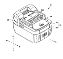
図1に、本発明による電池パックを装着した電動工具の一例を示す。図1の例では電動工具1としてコードレスドリルを用いた例を示している。電動工具1は、機器本体としての本体部2と、本体部2に対して着脱可能な電池パック10を有する。電池パック10は、本体部2の前後方向に沿って、ハンドル部3の延出方向先端部(下端部)に着脱可能に設けられる。電池パック10には操作部23が設けられ、操作部23は電池パック10を装着した際のロック機構として作用し、また電池パック10を取り外す際のリリースボタンとして作用する。図1に示すように、本体部2の前後方向に沿う矢印Aで示す方向を差し込み方向として、電池パック10をハンドル部3に差し込むと、電池パック10は電動工具1に装着される。一方、操作部23を押しながら矢印Aで示す方向と反対方向に電池パック10を移動させると、電池パック10をハンドル部3から取り外すことができる。
FIG. 1 shows an example of an electric tool equipped with a battery pack according to the present invention. In the example of FIG. 1, an example in which a cordless drill is used as the
本体部2は、図示せぬモータと、モータの駆動を制御する図示せぬ制御部を内蔵し、先端部分にドリルビット等の先端工具6を装着可能とする工具保持部2Aを有する。筒状の本体部2から、ハンドル部3が下方に延出し、その延出部分の基端部分には、トリガ8Aが設けられる。トリガ8Aは、図示せぬモータに電力供給するスイッチ(トリガスイッチ)となるもので、作業者がトリガ8Aを引くことによってモータの回転が開始する。
The
図2は、本発明の実施例に係るコードレス式の電動工具1の外観を示す別の角度からの斜視図であって、電池パック10を取り外して、上下を反転して下方向から見た状態を示す。ハンドル部3の延出方向端部(下端部)には、板状の複数の端子4(4A、4B、4C)が前方及び下方に向けて突出するように設けられる。複数の端子のうち、モータを駆動するための電流が流れる電力端子として、正極端子4A及び負極端子4Bが設けられる。さらに、過電流や過放電が生じた際に電動工具側の電流の流れを遮断させるための遮断制御信号を電動工具側に伝達するための信号伝達端子4Cが設けられる。
FIG. 2 is a perspective view from another angle showing the appearance of the
図3は図1に示す電池パック10の外観を示す斜視図である。電池パック10の装着方向は、図中Aにて示す方向である。電池パック10は、ハウジング20の内部に、複数の電池セルと、充電及び放電の制御を行う制御基板を収容したものであり、ハウジング20は上側ハウジング21と下側ハウジング22により上下分割式に構成される。上側ハウジング21の前方側の側面には操作部23が設けられる。上側ハウジング21の上面ほぼ中央付近には、端子挿入部24が形成され、電池パック10を端子4に対して前方側からスライドさせながら移動させる事によって、本体部2の端子4が端子挿入部24に差し込まれることによって、電池パック10と電動工具1が電気的に接続される。上側ハウジング21の端子挿入部24には、端子を挿入するための8つのスリット24Aが形成されるが、これらスリット24Aのすべてに接続端子を設ける必要はなく、これらのスリット24Aのうち必要な数だけ接続端子が設けられる。
FIG. 3 is a perspective view showing an appearance of the
図4は、図3に示す電池パック10の充電時の状態を示す斜視図である。電池パック10を充電する際には、図4に示すように、電池パック10を電動工具1から取り外して充電器99に装着する。充電器99は、交流100V等の商用電源を用いて、充電用の所定の電圧、所定の電流の直流を生成し、セットされた電池パック10に収納された電池セルを充電する。充電器99については、市販されている公知の充電器を用いることができ、本発明とは直接関係がないので、ここでの説明は省略する。
FIG. 4 is a perspective view showing a state when the
図5は、図3に示す電池パック10の分解斜視図である。電池パック10は、非導電性の部材で製造されたハウジング20を有し、ハウジング20の内部にケース30が収容される。ハウジング20は、プラスチック等の高分子樹脂を用いた一体成型で製造すると、強度的にも重量的にも好ましい。ハウジング20は主に、上側ハウジング21と、下側ハウジング22とからなり、これらはボス21Aとボス22Aを介して互いに嵌合される。ハウジング20には、下側ハウジング22の内部に、下から順に、ケース30、基板40及び端子カバー49が収容され、上側ハウジング21が被される。ハウジング20の前方両側部には、ハウジング20をハンドル部3に係止させるための一対の操作部23が取り付けられる。端子挿入部24は、端子カバー49によって基板40が外部に露出しないように覆われる。
FIG. 5 is an exploded perspective view of the
ケース30は、複数の電池セル収容部として、複数の電池セル32を保持するセルフレーム31と、複数の電池セル32の電極間を電気的に接続する電極部(図示せず)と、接続された電池セル32への2つの接続端子(図示せず)を有し、接続端子は基板40に接続される。電池セル32は、リチウムイオン電池等の二次電池であり、複数回充放電可能である。本実施例では、公称3.6Vのリチウムイオン電池を2本一組とし、これらを四組直列に接続して14.4Vの電圧を得ている。
The
基板40は、上側ハウジング21の内部に位置するように、ケース30の上方に固定される。基板40には、電池セル32への充電及び放電を制御するための制御回路が搭載される。基板40の上面には複数の端子42が配設される。本実施例においては、7本の端子42が適度な間隔を介して配設され、端子挿入部24を介して差し込まれた本体部2の端子4A〜4Cが対応する端子に嵌合される。尚、電池パック10の端子42は、様々な電動工具に装着する場合を考慮して複数分準備されるが(本実施例では7本)、電動工具に装着した際にこれらすべての端子42が用いられる訳ではなく、必要な端子42のみが接続される。
The
図6は、上側ハウジング21を外した状態の電池パック10の平面図である。7本の端子42(42A〜42G)は、基板40の一端から順に、充電用の正極端子42Aと、放電用の正極端子42Bと、信号伝達端子42C、42D、42Eと、充放電用の負極端子42Fと、信号伝達端子42Gとから構成される。正極端子42A、42Bは、ケース30の一方(プラス側)の電極部と接続され、負極端子42Fは、電池セル32の他方(マイナス側)の電極部と接続される。従って、電池セル32を充電するときは、正極端子42Aと負極端子42Fには充電電圧に応じた電流を流し、電池セル32を放電させるときは、正極端子42Bと負極端子42Fから、電動工具1の負荷に応じた電流を放電するように構成される。このように、正極端子42A、42B及び負極端子42Fは、電池セル32の充放電に応じた電流を、電池パック10と電動工具1との間で流すために使用される。
FIG. 6 is a plan view of the
信号伝達端子42C〜42E及び42Gは、それぞれ、収容される電池セルの種類や本数を識別するために使用される端子、過充電を検出するために使用される端子、サーミスタからの出力を伝達するための端子、過放電あるいは過電流を防止するために使用される端子である。信号伝達端子42C〜42E及び42Gを介して、電池パック10の充電や放電を制御する制御信号が伝達される。
Each of the
正極端子42A、42Bは、基板40の幅Lの中心を通って差し込み方向Aと平行に延在する仮想の中心線K−Kによって分割される一方の領域40Aに配置される。一方、負極端子42Fは、中心線K−Kによって分割された他方の領域40Bに配置される。すなわち、負極端子42Fは、正極端子42A、42Bのいずれか一方と、必ず中心線K−Kを間に介在させるように配設される。信号伝達端子42C〜42E及び42Gは、基板40において、正極端子42A、42B及び負極端子42Fの配置場所に対して適切な距離を介して配置される。本実施例では、基板40として両面基板を用い、基板40の上面及び下面には、後述する制御回路を構成する各種電子素子が搭載される。
The
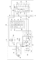
次に図7を用いて過電流保護回路の具体例について説明する。本発明に係る電動工具において、リチウムイオン二次電池からの過電流を防止する回路としては、電池パック10の内部の基板40に過電流保護回路を搭載する方法と、電動工具1の内部に過電流保護回路を搭載する方法と、電池パック10及び電動工具1の双方の内部に過電流保護回路を搭載する方法の3通りが考えられる。図7に示す例は、電池パック10の内部の基板40に過電流保護回路を搭載する例である。尚、本明細書では「過電流」とは、(1)放電するピーク電流が最大許容電流値を超える場合(ピーク許容電流)と、(2)放電する電流値が最大許容電流値より小さいものの、そのような大きな電流が所定許容時間以上(例えば十数秒から数十秒程度)流れ続ける場合(大電流許容持続時間)の二種類の状態がある。本実施例では主に(2)の大電流許容持続時間に着目し、本実施例による過電流保護回路は、例えば20A以上の電流が30〜50秒程度連続した場合に保護回路を作動させるように構成した。
Next, a specific example of the overcurrent protection circuit will be described with reference to FIG. In the electric power tool according to the present invention, as a circuit for preventing an overcurrent from the lithium ion secondary battery, an overcurrent protection circuit is mounted on the
図7は、本発明の実施例に係る過電流保護回路の回路図である。電池パック10の放電用の正極端子42Bと負極端子42Fは、電動工具1に設けられる正極端子4Aと負極端子4Bにそれぞれ接続される。電動工具1の正極端子4Aと負極端子4Bの間には、直流式のモータ5とトリガスイッチ8が直列に接続される。実際の電動工具1の回路上には、何らかの制御回路が介在されることが多いが、本実施例では説明を簡略化するために電動工具1の内部の回路構成はモータ5とトリガスイッチ8だけを記載している。
FIG. 7 is a circuit diagram of an overcurrent protection circuit according to the embodiment of the present invention. The
電池パック10には、電池セル組32A〜32Dを接続板で直列接続してなる複数の電池セルを収容するケース30が内包される。電池セル組32A〜32Dはそれぞれ2本の電池セルの並列接続で構成されるが、電池セル組32A〜32Dをそれぞれ1本の電池セルで構成しても良いし、3つ以上の電池セルの並列接続で構成するようにしても良い。電池パック10と電動工具1を接続して、電動工具1のトリガスイッチ8をオンにした場合に、ケース30の正極端子から電動工具1を介してケース30の負極端子に流れる放電電流経路が形成される。尚、電動工具1側の経路には、モータ5の回転速度を調整するための抵抗回路又は調速回路が含まれるのが通常であるが、本実施例では図示及び説明を省略している。
The
形成される放電電流経路のうち、電池パック10側の経路には、スイッチング部50、定電圧電源55、電池電圧検出部70、トリガ検出部83が接続される。これら各部は制御手段たるマイコン(マイクロコンピュータ)60に接続される。電池パック10には、更に、電池温度検出部75と表示部86が含まれ、これらもマイコン60に接続される。
The switching
マイコン60は、中央処理装置(CPU)61、ROM(Read Only Memory)62、RAM(Random Access Memory)63、タイマ64、A/Dコンバータ65、出力ポート66、リセット入力ポート67を含んで構成され、これらは内部バスにより相互に接続される。
The
スイッチング部50は、ケース30の負極側と電池パック10の負極端子42Fの間に接続され、マイコン60の制御により、電動工具1に流れる負荷電流をスイッチングする。スイッチング部50は、FET(電界効果トランジスタ)51、ダイオード52及び抵抗53、54から構成され、FET51のゲートには抵抗54を介してマイコン60の出力ポート66より制御信号が印加されるように接続される。FET51のソース・ドレイン間にはダイオード52が接続され、電池セル組32A〜32Dの充電時の充電電流経路を構成する。
The switching
電流検出部80は、FET51に流れる電流を検出するもので、入力側はダイオード52のカソードとFET51のドレインの接続点に接続され、出力側はマイコン60のA/Dコンバータ65に接続される。電流検出部80は、反転増幅回路と非反転増幅回路の両方を備えた構成で、FET51のオン抵抗及びダイオード52のオン電圧に基づき、その流れる電流の方向によって生じる電位を、反転増幅及び非反転増幅する。充電及び放電に対応して反転増幅回路または非反転増幅回路に出力が生じ、この出力に基づきマイコン60のA/Dコンバータ65はA/D変換を行う。
The
定電圧電源55は、3端子レギュレータ56、平滑コンデンサ57、58、リセットIC59から構成されており、定電圧電源55から出力される定電圧VCCは、電池温度検出部75、マイコン60及び電流検出部80、表示部86の電源となる。リセットIC59はマイコン60のリセット入力ポート67に接続され、マイコン60を初期状態にするためにリセット信号を出力する。
The constant
電池電圧検出部70は、ケース30の電池電圧を検出するためのもので、3つの抵抗71〜73からなる。ケース30の正極端子とアース間に直列接続された抵抗71、72の接続点は、抵抗73を介してマイコン60のA/Dコンバータ65に接続される。A/Dコンバータ65からは、検出した電池電圧に対応するデジタル値が出力され、マイコン60のCPU61は、変換されたデジタル値と第一所定電圧及び第二所定電圧とを比較する。第一所定電圧と第二所定電圧はマイコン60のROM62に予め記憶されているもので、第一所定電圧は過充電と見なす電圧値であり、第2所定電圧は過放電と見なす電圧値である。
The battery
電池温度検出部75は、ケース30の近傍に配置して電池セル32A〜32Dの温度を検出するものであり、感温素子のサーミスタ76及び、抵抗77〜79から構成される。サーミスタ76は抵抗78を介してマイコン60のA/Dコンバータ65に接続される。A/Dコンバータ65からは、検出した電池温度に対応するデジタル値が出力され、マイコン60のCPU61は、出力されたデジタル値と予め設定した所定値とを比較し、電池温度が異常高温であるかどうかの判断を行う。
The battery
トリガ検出部83は抵抗84と抵抗85とからなり、電動工具1のトリガスイッチ8のオン動作を検出する。トリガスイッチ8がオン状態になると、モータ5の直流抵抗は非常に小さい(数オーム程度)ために、FET51のドレイン・ソース間にはほぼ電池電圧が印加され、この電圧を抵抗84、85で分圧してA/Dコンバータ65へ入力することにより、CPU61はトリガスイッチ8のオン動作を検出することができる。
The
表示部86はLED(発光ダイオード)87と抵抗88からなり、マイコン60の出力ポート66の出力に応じてLED87を点灯又は点滅させる。表示部86は、たとえば、電池温度検出部75で検出した電池温度が所定温度よりも高い場合には、電池温度異常表示を行う。このLED87は図3では図示されていないが、例えば電池パック10の前面の任意の位置に設けるようにすれば良いし、作業者の目に付きやすいその他の任意の位置に設ければ良い。
The
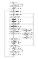
次に図8を用いて、本発明に係る電動工具に用いられるリチウムイオン二次電池を過電流から保護するための制御手順を説明する。図8のフローチャートで示す制御は、マイコン60のCPU61を用いてプログラムを実行することによりソフトウェア的に実行できる。
Next, a control procedure for protecting the lithium ion secondary battery used in the power tool according to the present invention from overcurrent will be described with reference to FIG. The control shown in the flowchart of FIG. 8 can be executed by software by executing a program using the
電動工具1に電池パック10が装着され、トリガ8Aが引かれるとトリガスイッチ8がオンになる。CPU61は、まずトリガスイッチ8がオンになったかどうかを検出し、オンになるまで待機する(ステップ401)。トリガスイッチ8がオンになったら、CPU61は出力ポート66から所定の電圧をFET51のゲートに出力することにより、FET51をオン(ソース−ドレイン間が導通)にする(ステップ402)。これによって、モータ5に直流電力が供給され、モータ5が起動する。次に、CPU61はタイマ64を使って時間間隔の測定を開始する(ステップ403)。
When the
本実施例においては、CPU61は3つの時間間隔を測定するために、T1タイマ、T2タイマ、T3タイマを設定する。T1タイマは、電流検出部80の出力を用いて電流を検出するサンプリング間隔(10ミリ秒)をカウントするためのタイマである。T2タイマは、所定の大電流又は中電流(例えば平均20A以上)が所定時間(例えば50秒)連続して流れたか否かの継続時間をカウントするためのタイマである。T3タイマは、T2タイマでカウントする所定電流値が所定電流以下に低下してから所定時間(例えば5秒)経過したか否かをカウントするためのタイマであり、いわば過電流監視状態から通常の状態への復帰時間をカウントするためのタイマである。
In this embodiment, the
FET51がオンになりモータ5が始動すると、CPU61はT1タイマのカウントを開始する(ステップ403)。次にCPU61は、T1タイマのカウントを更新し(ステップ404)、T1タイマのカウント値が10ミリ秒(mS)経過したか否かを判定する(ステップ405)。T1タイマのカウント値が10ミリ秒経過していない場合はステップ404に戻り、経過している場合、CPU61は電流検出部80の出力を用いて電流を検出し(ステップ406)、検出された電流値をRAM63に格納することにより、平均電流算出のための放電電流値を順次累積する。(ステップ407)。
When FET51 is the
次に、T1タイマのカウント値が時間Tαを経過したか否かを検出する(ステップ408)。時間Tαはいわゆる不感時間と言われるもので、このTα以下の時間間隔では電流の平均値を算出しないことを意味する。時間Tαが経過していないときはステップ404に戻り、経過しているときはRAM63に格納された放電電流値を用いて放電電流の平均値を算出する(ステップ409)。放電電流の平均値は、RAM63に格納された放電電流値のうち直近Tα時間分のデータを取り出して平均値を求めることによって算出できる。従って、本実施例では、Tα>10ミリ秒とすることが重要である。また、不感時間たる時間Tαは、例えばモータ5の始動電流の流れる期間よりも十分大きく設定し、時間Tα毎に放電電流の平均値を算出しても、始動電流の平均値が所定の電流(例えば20A)を越えないような時間間隔とすると、モータ5の始動電流が以降のステップで検出されないので、実質的に始動電流を過電流として検出することを排除できる。
Then, the count value of the T 1 timer for detecting whether the elapsed time T alpha (step 408). Those time T alpha so-called dead time, which means that it does not calculate the average value of the current in the time interval following the T alpha. It returns to step 404 when not the elapsed time T alpha is, when has passed and calculates the average value of the discharge current with the discharge current value stored in the RAM 63 (step 409). The average value of the discharge current can be calculated by taking out the data for the latest Tα time from the discharge current values stored in the
次に、CPU61は算出された放電電流平均値が所定の電流たる20Aを越えたか否かを判定する(ステップ410)。この所定の電流は、電動工具又は電池パックの設計者が任意に設定できるものであり、二次電池の放電特性やモータ5の特性に応じて設定できる。本実施例では、一つの基準として所定電流を20Aと設定したが、これだけに限られない。尚、連続放電を許容する基準放電電流だけでなく、一瞬の放電がおこっても即座に遮断させる許容最大電流値をも設定することができるので(本実施例では説明されていない)、連続放電を許容する基準放電電流は、許容最大電流値の20%〜90%程度に設定すると好ましい。
Next, the
次に、ステップ411において、CPU61はT2タイマを更新し(ステップ411)、T3タイマをクリアする(ステップ412)。次に、CPU61はT2タイマの積算値が30秒以上になったか否かを判定する(ステップ413)。T2タイマの積算値が30秒に達していない場合は、ステップ404に戻る。
Next, in
ステップ410において、算出された放電電流平均値が所定の電流たる20A以下の場合は、CPU61はT3タイマのカウントを更新し(ステップ419)、T3タイマのカウント値が5秒以上、即ち、算出された放電電流平均値20A以下の状態が5秒以上続いたかを判定し(ステップ420)、5秒以上続いた場合には大電流の連続放電状態が停止したとしてT2タイマをクリアしてステップ404に戻る(ステップ421)。ステップ420において、算出された放電電流平均値20A以下の状態が5秒未満の場合は、ステップ404に戻る。
In
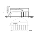
ステップ413において、算出された放電電流平均値20A以上が30秒以上経過の場合は、作業者に対して大電流の連続放電状態(過電流状態)が継続していることを知らせるためのアラームを発する。このアラームの発し方は種々考えられるが、本実施例では、CPU61が、5秒のうち1秒間だけFET51に対して供給する電流値を下げるようにパルス駆動を行う。このパルス駆動時の駆動状態を示すのが図9である。
In
図9は、図7の過電流保護回路動作時の電流波形図である。横軸が経過時間(秒)、縦軸が電池パック10からの放電電流値(単位A)であり、経過時間に伴う放電電流の例を示すのが放電曲線90である。時間t0にてトリガ8Aが引かれると、モータ5には多大な始動電流が流れ、その電流値は時間t1にて矢印91に示すように20Aを遙かに超える。モータ5の種類によっては、この始動電流が100Aを越える場合もある。しかしながら、始動電流の流れる時間は短く、20A以上となるTβはせいぜい100ミリ秒以内である。ここで、不感時間Tαは、Tβの2〜4倍程度の時間とすることが好ましく、このように不感時間Tαを長めに取ることによって始動電流と継続的に流れる大電流とを区別することができる。
FIG. 9 is a current waveform diagram when the overcurrent protection circuit of FIG. 7 operates. The horizontal axis represents the elapsed time (seconds), the vertical axis represents the discharge current value (unit A) from the
時間t1においてモータ5に始動電流が流れてモータ5が加速し始めると、モータ5に流れる電流は低下し、矢印92の点で再び増加を始める。その後、モータ5の回転数や負荷の大きさに応じて電流値は変動するが、矢印93の時点で所定の電流、本実施例では放電電流20Aを越えることになり、この時点でT2タイマによる大電流の継続時間のカウントを開始する。尚、実際の電動工具1において測定した放電電流をそのままグラフ化すると電流の変動があり図9のような滑らかな放電曲線にならないが、本実施例では直近のTα時間の放電平均電流値を用いてグラフ化しているので、電流変動の影響を少なくすることができる。
When a starting current flows through the
そして、時間t3(矢印94の時点)で20A以上の放電電流が30秒続いたので、図8のステップ414で示したようにアラーム動作として1秒間だけ放電電流をスイッチングする。このスイッチング動作は、1秒間という短い時間だけ放電電流の平均値を低下させることにより電動工具の出力を低下させ、作業者に過電流状態であることを認識させるものである。スイッチング動作は、マイコン60がFET51を制御することにより実行される。
Then, since the discharge current of 20 A or more continued for 30 seconds at time t 3 (at the time indicated by the arrow 94), the discharge current is switched only for 1 second as an alarm operation as shown in
図9の下側の放電曲線90は、スイッチング動作時の電流波形を拡大したものである。ここでは、時間t3秒から(t3+1)秒までの1秒間の放電曲線90を示す。CPU61(図7参照)は、スイッチング動作時に10ミリ秒(mS)毎にFET51(図7参照)をオン又はオフを周期的に繰り返すように制御する。この結果、時間t3秒から(t3+1)秒までの1秒間にFET51がオンの状態が50回、オフの状態が50回、交互に存在することになる。このように、本実施例では5秒間隔毎に最初の1秒間だけFET51のスイッチング動作を行うことにより、スイッチング動作中の平均放電電流を約半分に低下させることができる。スイッチング動作を行うことによって、作業者は若干の出力低下が起こったことを感じ取ることができ、このスイッチング動作は作業者へのアラーム機能として役に立つ。このように、作業者が電動工具の動作状態に違和感を覚えることができるように構成したので、作業者は電池パック10からの大電流(又は中電流)放電状態が続いていること、そのままトリガ8Aを引き続けるとまもなくモータ5が強制的に停止される状態にあることを容易に知ることができる。
A
本実施例で示した、アラーム動作を行う開始時点(t2から30秒後)や、アラーム動作の実行間隔(5秒毎)や、スイッチング動作時間(1秒間)は例示であって、これらの時間は任意に設定できる。また、FET51をオン又はオフさせる時間間隔(オンが10ミリ秒、オフが10ミリ秒)も同様に例示であって、任意の間隔、任意の時間比率で行うようにしても良い。これらの時間は、電池パック10に内蔵する電池セル32の特性や、電動工具1のモータ5の特性、考えられる電動工具1の使用条件などを考慮の上、適宜設定すればよい。
Shown in this embodiment, (30 seconds after t 2) starting time of an alarm operation and execution intervals (every 5 seconds) and the alarm operation, the switching operation time (1 sec) is illustrative of these Time can be set arbitrarily. Similarly, the time interval at which the
本実施例では、アラーム動作が行われたにも拘わらずに、作業者がトリガ8Aを引き続けて作業を継続した場合には、所定の時間(t3から50秒)を経過した時間t4(矢印95の時点)において、CPU61がFET51をオフさせるように制御することによってモータ5が強制的に停止される。
In this embodiment, despite the alarm operation is performed, if the operator continues the working Hikitsuzuke the
再び図8に戻り、ステップ415において算出された放電電流平均値20A以上が50秒以上経過の場合は、CPU61はFET51をオフにする(ステップ416)。そして、作業者によってトリガスイッチ8がオフにされるまで待機し(ステップ417)、オフにされたらCPU61はFET51を再びオンにしてからステップ403に戻る(ステップ418)。
Returning to FIG. 8 again, when the discharge current
以上、本実施例によれば、過大なピーク放電電流時の遮断機能によって遮断できないような、大電流又は中電流の長時間放電の場合にも、電動工具のモータを強制的に停止することができるので、電池パックの過電流状態、特に大電流連続放電状態を避けることができ、電池パックの劣化を効果的に防止することができる。 As described above, according to the present embodiment, the motor of the electric tool can be forcibly stopped even in the case of a long discharge of a large current or a medium current that cannot be interrupted by the interrupt function at the excessive peak discharge current. Therefore, an overcurrent state of the battery pack, particularly a high current continuous discharge state can be avoided, and deterioration of the battery pack can be effectively prevented.
次に、図10及び図11を用いて本発明の第2の実施例に係る過電流保護回路について説明する。第2の実施例も第1の実施例と同様に、電池パック10の基板40に搭載されたマイコン60を用いて電池パック10内で過電流状態を検出するように構成した。しかしながら、マイコン60で実行するプログラムが異なり、第1の実施例に比べてより高度な過電流保護を行うように構成した。
Next, an overcurrent protection circuit according to a second embodiment of the present invention will be described with reference to FIGS. Similarly to the first embodiment, the second embodiment is configured to detect an overcurrent state in the
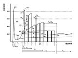
図10は、第2の実施例に係る過電流保護回路の動作時の電流波形図である。横軸が経過時間(秒)、縦軸が電池パック10からの放電電流値(単位A)であり、放電電流値を示すのが放電曲線450である。本図では、放電を示す放電曲線450が矢印452又は453から別れて、曲線A〜曲線Fの6つの放電パターンとなる例を示している。まず時間t0にてトリガ8Aが引かれると、モータ5には多大な始動電流が流れ、その電流値は時間t1にて矢印451に示すように80Aを超える。モータ5の種類によっては、この始動電流が100Aを越える場合もある。しかしながら、始動電流の流れる継続時間は短く、10A以上となるT1はせいぜい0.5秒程度である。ここで、T0からT1においては、本実施例における過電流保護回路の不感時間に設定すれば、モータ5の始動電流と、監視すべき過電流とを区別することができる。
FIG. 10 is a current waveform diagram during operation of the overcurrent protection circuit according to the second embodiment. The horizontal axis represents the elapsed time (seconds), the vertical axis represents the discharge current value (unit A) from the
時間t1においてモータ5に始動電流が流れてモータ5が加速し始めると、モータ5に流れる電流は低下し、矢印452の点で再び増加を始める。電動工具1が、図1に示したようなコードレスドリルであって先端工具が木工用ドリルの場合のように、負荷が小さい場合は、曲線Aのようにt2からt3に至り僅かに放電電流が上昇するだけで、その後はそのままの状態で継続する(但し、木工用ドリルの場合は作業が10秒以内に終わるのが普通である)。この場合は、放電電流値が本実施例における過電流保護を行うための最低の閾値(20A)に到達しないのでマイコン60による過電流保護動作は何ら行われない。
When a starting current flows through the
曲線Cは、第1の実施例で説明した状態と同じ制御の放電電流パターンである。時間t1においてモータ5に始動電流が流れてモータ5が加速し始めると、モータ5に流れる電流は低下し、矢印452の点で再び電流値が増加を始め、矢印453で放電電流値が20Aを越える。すると、マイコン60は過大電流の遮断時間T20(過大電流20A時の遮断時間Tという意味)を50秒(=t8−t3)と設定する。この場合、曲線Cのような放電パターンの場合は、t3から40秒経過後に、マイコン60はFET51を10ミリ秒ごとにオン及びオフの制御を行うアラーム動作を1秒間行う。尚、第2の実施例ではアラーム動作を行う時間を30秒でなく40秒に設定している。
A curve C is a discharge current pattern under the same control as the state described in the first embodiment. When the starting current flows through the
一方、曲線Bの場合は、マイコン60は時間t3にて過大電流の遮断時間T20を設定するものの、T20が経過する前(t7の直後)に、矢印454に示すように再び電流値が20A以下に低下するので大電流状態が脱却され、この脱却状態がT3秒(>5秒)続くので、時間t3を基点とした遮断時間T20のカウントがクリアされる。しかしながら、矢印455で示す時間t9にて再び電流値が20Aを越えるので、時間t9を基点に再び過大電流の遮断時間T20が設定され、トリガ8Aが離されるまで同様の制御が繰り返される。
On the other hand, in the case of curve B, although the
次に、曲線Dの場合は、矢印452の点で電流値が再び増加を始め矢印453で、放電電流値が20Aを越え過大電流の遮断時間としてT20が設定される。その後さらに放電電流値が上昇し、矢印456の点で40Aを越える。そこで、マイコン60は過大電流の遮断時間をT20からT40に置き換える。T40は連続放電電流値が40Aを越える場合の遮断時間であり、T40はT20に比べて短くなるように設定され、本実施例では30秒である。尚、T40の測定の基点は、矢印456の時点(時間t6)ではなく時間t3のままとすると良い。過大電流の遮断時間T40を置き換えると、FET51を10ミリ秒ごとにオン及びオフ制御するアラーム動作の実施タイミングも早くする必要がある。例えば、T40を40秒とすると、アラーム動作の実施タイミングをt3から30秒とすれば良い。アラーム動作の実施間隔は5秒毎とし、最初の1秒間だけ10ミリ秒毎のFET51のオン又はオフの動作を繰り返すと良い。
Then, in the case of curve D, the
次に、曲線Eの場合は、矢印453で放電電流値が20Aを越え過大電流の遮断時間としてT20が設定され、矢印457の点で放電電流値が40Aを越えたので遮断時間T20がT40に置き換えられ、矢印458の点で放電電流値が60Aを越えたので遮断時間T40がT60に置き換えられる。T60はT40に比べて短くなるように設定され、本実施例では10秒である。T60の測定の基点はt3のままとして変更しない。このように基点を時間t3で変えないようにすれば、T2タイマによるカウント値をそのまま用いることができるので、時間管理がし易い。遮断時間T60を設定した場合であっても、遮断時間T60が経過する前に、遮断をする前のアラーム動作として1秒間だけ放電電流をスイッチングする。遮断時間T60を10秒とした場合は、アラーム動作の開始時刻を5秒とすると良い。
Next, in the case of curve E, the discharge current value exceeds 20 A at
次に、曲線Fの場合は、矢印453で放電電流値が20Aを越え過大電流の遮断時間としてT20が設定され、矢印459の時点で放電電流値が40Aを越えたので遮断時間T20がT40に置き換えられ、矢印460の時点で放電電流値が60Aを越えたので遮断時間T40がT60に置き換えられ、矢印461の時点で放電電流値が80Aを越えたので遮断時間T60がT80に置き換えられる。放電電流値が80Aを越えるということは、ほとんど即時に遮断すべき過大な電流であるので、T80は十分短い時間に設定され、例えば0.5秒に設定される。また、遮断時間T80を用いて遮断する場合には、遮断をする前のアラーム動作を行う時間的余裕はないので、CPU61はアラーム動作による事前予告無しにいきなり放電電流を遮断させる。T80の測定の基点は、t3のままとするので、矢印461の時点でt3からT80秒以上経過している場合には、CPU61は即座にFET51をオフにして放電電流を遮断する。
Next, in the case of curve F, the discharge current value exceeds 20 A at
以上のように、第2の実施例では放電電流の大きさに基づいて、許容持続時間を変化させるように制御するので、放電電流の大きさに基づいた高精度の過電流保護を行うことができる。尚、上述の実施例では、T20→T40→T60のように変更した際に、変更後の時間カウントの起点(図ではt3)をそのまま維持するようにしたが、維持しないでT20→T40→T60のように変更する毎にT2タイマによるカウントを開始させるようにしても良い。また、T20→T40→T60のように変更した遮断時間の経過前に、電流値が設定した遮断時間に対する基準電流値を一定時間下回った場合は、再びT60→T40→T40のように遮断時間を再設定するように制御しても良い。 As described above, in the second embodiment, since the allowable duration is controlled based on the magnitude of the discharge current, it is possible to perform highly accurate overcurrent protection based on the magnitude of the discharge current. it can. In the above-described embodiment, when the change is made as T 20 → T 40 → T 60 , the starting point of the time count after the change (t 3 in the figure) is maintained as it is. it may be caused to start counting by the T 2 timer each time be changed as 20 → T 40 → T 60. If the current value falls below the reference current value with respect to the set cutoff time before the cutoff time changed as T 20 → T 40 → T 60 elapses, T 60 → T 40 → T 40 again. Control may be performed so as to reset the shut-off time as described above.
次に、図11のフローチャートを用いて、本発明の第2の実施例に係る過電流保護回路の動作を説明する。図11のフローチャートで示す制御は、図8で示したフローチャートと同様に、マイコン60を用いてプログラムを実行することによりソフトウェア的に実行できる。第1の実施例では、マイコン60は、T1タイマ、T2タイマ、T3タイマの3つのタイマを用いる。T2タイマ、T3タイマは第一の実施例と同じ用途で用いられるが、T1タイマは第1の実施例のT1タイマと異なる。T1タイマは、始動電流を検出しないために、トリガを引いてから一定の時間だけ電流検出を行わない不感時間を検出するためのタイマである。T2タイマは、所定電流以上が継続して流れる時間をカウントするためのタイマである。T3タイマは、所定電流以上流れていた電流が所定値以下に低下してから一定の時間経過したか否かをカウントするためのタイマであり、復帰時間をカウントするためのタイマである。
Next, the operation of the overcurrent protection circuit according to the second embodiment of the present invention will be described with reference to the flowchart of FIG. The control shown in the flowchart of FIG. 11 can be executed by software by executing a program using the
電動工具1に電池パック10が装着され、トリガ8Aが引かれてトリガスイッチ8がオンになると(ステップ501)、CPU61は出力ポート66から所定の電圧をFET51のゲートに出力することにより、FET51をオン(ソース−ドレイン間が導通)させる(ステップ502)。これによって、モータ5には電池パック10からの直流電力が供給され、モータ5が始動する。次に、CPU61は始動電流に起因するピーク電流を許容するため、不感時間の経過をカウントするT1タイマのカウントを始める(ステップ503)。本実施例では、不感時間として0.5秒とする。ステップ504においてT1タイマが0.5秒に到達していなければ、ステップ521に進みトリガスイッチ8の動作に変化があったか否かを判定し、トリガスイッチ8がオンのままであったらステップ503に移り、トリガスイッチ8がオフになったらステップ501に戻る(ステップ521)。
When the
ステップ504で、T1タイマが0.5秒に到達した場合はT1タイマをクリアし(ステップ505)、CPU61は放電電流平均値I1を算出する(ステップ506)。放電電流は、所定のサンプリング間隔(例えば10ミリ秒間隔)毎に計測され、計測値が順次RAM63(図7参照)に格納される。放電電流平均値I1は取得された複数の計測値のうち、直近50ミリ秒の間に計測された電流値の平均である。同様にしてCPU61は、取得された複数の電流値のうち、直近3秒の間に計測された電流値から放電電流平均値I2を算出する(ステップ507)。尚、放電電流平均値I1、I2を算出するための時間50ミリ秒、3秒が未経過の場合は放電電流平均値I1、I2を計算しないでゼロのままとするか、少ない計測値の平均を取るようにしても良い。
In
次に、CPU61は放電電流平均値I1が80A以上か否かを判断し(ステップ508)、以上の場合は、アラーム動作(パルス駆動)をするまでの時間TPを0.5秒、FET51を遮断させるための時間TSを0.5秒に設定し(ステップ509)、ステップ516に進む。ここでTP=TSとしたのは、I1≧80Aの場合にはアラーム動作を行うことなくFET51をほぼ瞬時にオフさせるためである。
Then,
ステップ508でI1<80Aの場合は、放電電流平均値I2が60A以上か否かを判断し(ステップ510)、I2≧60Aの場合はアラーム動作(パルス駆動)をするまでの時間TPを5秒、FET51を遮断させるための時間TSを10秒に設定し(ステップ511)、ステップ516に進む。このように設定すると、放電電流平均値I2が20Aを越えてから5秒後に1秒間だけアラーム動作(パルス駆動)が実行され、アラーム動作が終了して4秒後(I2が20Aを越えてから10秒後)にFET51がオフになるように設定される。
If I 1 <80 A in
ステップ510でI2<60Aの場合は、放電電流平均値I2が40A以上か否かを判断し(ステップ512)、I2≧40Aの場合はアラーム動作(パルス駆動)をするまでの時間TPを20秒、FET51を遮断させるための時間TSを30秒に設定し(ステップ513)、ステップ516に進む。同様にして、ステップ512でI2<40Aの場合は、放電電流平均値I2が20A以上か否かを判断し(ステップ514)、I2≧20Aの場合はアラーム動作(パルス駆動)をするまでの時間TPを40秒、FET51を遮断させるための時間TSを50秒に設定し(ステップ515)、ステップ516に進む。
If I 2 <60 A in
ステップ514で放電電流平均値I2が20Aを下回ったときは、放電平均電流が小さくなったときにタイマT2をクリアするためのT3タイマのカウントを開始し(ステップ523)、T3タイマが5秒を越えていたら、T2タイマをクリアしてステップ522に進む(ステップ524、525)。ステップ524で、T3タイマが5秒未満の場合は、ステップ522に進む。ステップ522では、トリガスイッチ8がオンのままで有るかを判断し、オンのままであったらステップ506に進み、オフであったらステップ501に進む。
When the discharge current average value I 2 is below 20A in
ステップ516においてT3タイマをクリアしたのち(ステップ516)、T2タイマのカウント値を更新する(ステップ517)。次に、T2タイマのカウント値が、アラーム動作を行うための設定値TS以上であるか否かを判定し(ステップ518)、FET51を遮断させるための時間TSに到達していたら、CPU61はFET51をオフにすることによってモータ5に供給される直流電力を遮断する(ステップ519)。そして、作業者によってトリガ8Aが戻されてトリガスイッチ8がオフになるまで待機し(ステップ520)、オフにされたらステップ501に戻る。
After clearing the T 3 timer in step 516 (step 516), and updates the count value of T 2 timer (step 517). Then, the count value of T 2 timer, it is determined whether the set value T S or more for an alarm operation (step 518), if not reach the time T S for causing shut off the
ステップ518において、T2タイマのカウント値がTS未満の場合は、CPU61はT2タイマの値がTP以上であるかを判定し、TP以上の場合は、CPU61はFET51をパルス動作させることによって、作業者に対して大電流の連続放電状態(過電流状態)が継続していることを知らせるためのアラームを発する(ステップ527)。このパルス駆動の状態は、図9の下側の図で示したのと同様に、5秒間隔毎に、最初の1秒間だけ10ミリ秒ごとにFET51をオン又はオフさせるスイッチング動作を行う制御である。
In
以上、第2の実施例によれば電池パック10からの放電電流の大きさに応じて、許容連続放電時間を可変に設定できるので、ロック電流など過大な電流が流れる場合は即座にFET51をオフさせることにより確実に電池パック10及び電動工具1を保護することができる。また、電池パック10からの放電を遮断させるための閾値を複数設けたので、電動工具の特性や使用状態に応じたきめ細かな大電流連続放電状態からの保護ができ、電池パック10の劣化を防止するだけでなくモータ5の損傷を未然に防止することができる。さらに、第2の実施例の制御は電池パック10に含まれるマイコン60でプログラムを実行することにより実現しているので、プログラムの変更だけで多彩な過電流保護制御を実現できる。
As described above, according to the second embodiment, since the allowable continuous discharge time can be variably set according to the magnitude of the discharge current from the
次に図12及び図13を用いて本発明の第3の実施例に係る過電流保護回路について説明する。第1の実施例においては、電池パック10の基板40にマイコン60が搭載され、このマイコン60を用いて電池パック10内で過電流状態を検出するように構成した。第3の実施例は、電池パック210の基板240に過電流保護回路を搭載する点では第1の実施例と同じであるものの、マイコンを用いないで専用の電池保護IC253を用いた回路で実現した点にある。また、過電流を遮断するためのFETを電池パック210の内部に設けるのではなく電動工具101側に設け、そのFETを外部から制御可能として、電池パック210側からFETのオン又はオフを制御するようにした。第2の実施例と同じ構成の部分には同じ参照符号を付している。
Next, an overcurrent protection circuit according to a third embodiment of the present invention will be described with reference to FIGS. In the first embodiment, the
図12は、本発明の第3の実施例に係る電池パック210の断面図である。電池パック210は図5で説明した電池パック10と、収容する電池セル250の本数を除いて基本的に同じ構成である。収容する電池セル250は、公称電圧3.6Vのリチウムイオン電池を4本直列に接続したものである。電池セル250は、4本並べてケース225に収容され、ハウジング220の上側ハウジング221と下側ハウジング222の間に配置される。ケース225の上側と、上側ハウジング221の間には基板240が配置され、基板240には正極端子147と負極端子143が設けられる。
FIG. 12 is a cross-sectional view of a
図13は、本発明の第3の実施例に係る過電流保護回路の回路図である。図13において、電動工具101と電池パック210とは、正極端子147、負極端子143、過電流過放電出力端子156を介して着脱可能に接続される。電池パック210には、過充電出力端子157も設けられるが、この端子は充電器99と接続されるものであり、電動工具101には接続されない。電動工具101は、電池パック10から供給される電力により駆動されるモータ105と、手動で切換可能なトリガスイッチ108を有するスイッチユニット103と、モータ105の回転を停止させるコントローラ104を含んで構成される。
FIG. 13 is a circuit diagram of an overcurrent protection circuit according to the third embodiment of the present invention. In FIG. 13, the
電池パック210は、予め所定電圧以上に充電された状態で電動工具101に接続されることにより、正極端子147と負極端子143との間に所定電圧を供給する。トリガスイッチ108が閉じてFET121がオンとなると、正極端子147と負極端子143との間にモータ105を経由する閉回路が形成され、モータ105は、所定の電力が供給されて駆動される。
The
電池パック210は、複数の電池セル250を直列に接続した電池セル群251と、正極端子147と電池セル群251との間に接続された抵抗252と、各電池セル250の過放電、過電流、および過電圧を検出して検出結果に応じた信号を電動工具101あるいは充電器に出力する電池保護IC253を含んで構成される。電池保護IC253や抵抗252は、図11で示した基板240上に搭載される。
The
抵抗252及び電池セル群251は、正極端子147と負極端子143との間に、直列に接続される。電池セル群251を構成する電池セル250は、例えばリチウムイオン電池等の二次電池である。電池保護IC253は、各電池セル250の過放電および過電流を監視し、いずれかの電池セル250で過放電または過電流を検出すると、過電流過放電出力端子156を介してモータ105への電力供給を遮断するための信号をコントローラ104に出力する。また、電池保護IC253は、電池セル250が過充電であることを検出すると、過充電出力端子157を介して充電器へ充電を停止するための信号を出力する。本実施例では、リチウムイオン電池の定格は、電池セル250の1個当たり3.6Vで最大充電電圧が4.2Vであり、4.35V以上となったときに過充電であると判断される。また、過電流とは、負荷に流れる電流が所定値を超えた状態のことを指し、本実施例では過電流となる電流は20A以上の放電電流が所定時間(例えば十数秒から数十秒)継続することをも含む。過放電とは、各電池セル250の残電圧が所定値を下回った状態のことを指し、本実施例では過放電となる1つの電池セル250の電圧を2Vとする。
The
電池保護IC253は、素電池電圧検出部230、過電圧検出部235、過放電検出部234、過電流検出部233およびスイッチ238を含んで構成される。素電池電圧検出部230は、各電池セル250の個々の電圧を検出し、検出結果を過電圧検出部235および過放電検出部234に出力する。
The
過電圧検出部235は、素電池電圧検出部230から各電池セル250の電圧を入力され、いずれかの電池セル250の電圧が一定値以上の場合には過電圧が生じていると判断する。過放電検出部234は、素電池電圧検出部230から各電池セル250の電圧を入力され、いずれかの電池セル250の電圧が一定値以下の場合には過放電が生じていると判断し、スイッチ238を閉じる(オン)ための信号を出力する。
The
過電流検出部233は、抵抗252を流れる電流値を検出し、検出した電流が許容最大電流値を越えた場合には過電流が生じていると判断し、スイッチ238を閉じるための信号を出力する。過放電検出部234又は過電流検出部233からの信号によりスイッチ238が閉じられると、過電流過放電出力端子156とグランドラインとが接続される。従って、その場合には、電池保護IC253は、電動工具101のコントローラ104に0ボルト(Lo信号)を出力することとなる。
The
大電流検出回路241は抵抗252を流れる電流が20A以上か否かを検知し、20A以上であれば、タイマカウンタ242に信号を出力する。タイマカウンタ242はその信
号が入力されると、タイマのカウントを開始し、50秒が経過するとスイッチ238にスイッチ238を閉じる(オン)ための信号を出力する。スイッチ238が閉じると上述のように電池保護IC253は、過電流過放電出力端子156を介して電動工具101のコントローラ104に0ボルト(Lo信号)を出力する。大電流検出回路241が検出した電流が20Aを下回った場合は、大電流検出回路241は復帰回路243に信号を出力する。復帰回路243はその信号が入力されると、上述とは別のタイマのカウントを開始し、5秒が経過するとタイマカウンタ242にタイマをリセットするための信号を出力する。
The large
このように、電流が20A以上である状態が50秒間継続すると、電池保護IC253は電動工具101のコントローラ104に0ボルト(Lo信号)を出力する。電流が20A以上となってもその状態が50秒間経過する前に電流が20Aを下回ると、タイマカウンタ242のタイマのカウントは一時停止される。電流が20Aを下回る状態が5秒間継続すると、復帰回路243によってタイマカウンタ242のタイマのカウントがリセットされる。これにより、再び電流が20A以上となってもその状態がさらに50秒間継続しない限りは、電動工具101のコントローラ104に0ボルト(Lo信号)は出力されない。
Thus, when the state where the current is 20 A or more continues for 50 seconds, the
電動工具101のモータ105は、スイッチユニット103およびコントローラ104を介して正極端子147および負極端子143に接続される。スイッチユニット103はモータ105に接続され、トリガスイッチ108と、正逆スイッチ109を備える。トリガスイッチ108は、モータ105と直列に接続され、作業者に操作されることにより、モータ105のオン又はオフする。正逆スイッチ109は、正極端子147と負極端子143に接続されるモータ105の極性を反転させ、回転方向を変更するためのスイッチである。
The
コントローラ104は、電池保護IC253から電力供給遮断のための信号が入力されると、FET121をオフにすることによりモータ105への電力供給のための閉回路を遮断し、電動工具101を停止させる。コントローラ104は、メイン電流スイッチ回路120、メイン電流スイッチオフ保持回路130および表示部140で構成される。
When a signal for shutting off the power supply is input from the
メイン電流スイッチ回路120は、FET121、抵抗122、およびコンデンサ123で構成される。FET121は、ドレインがモータ105に、ゲートが過電流過放電出力端子156に、ソースが負極端子143にそれぞれ接続される。抵抗122は、正極端子147とFET121のゲートとの間に接続される。コンデンサ123は、FET121のゲートとソースとの間に接続される。FET121のゲートと、抵抗122と、コンデンサ123との接点を接点124とする。
The main
FET121は、電池パック210からモータ105に正常に電力が供給されている間はオン状態である。すなわち、電動工具101と電池パック210が接続されると電池電圧が抵抗122を介して接点124(FET121のゲート)に印加されるためFET121はオンとなる。一方、電池保護IC253で過放電または過電流が検出されて、過電流過放電出力端子156からFET121のゲートに0ボルト(Lo信号)が入力されると、FET121はオフし、モータ105への電力供給を遮断する。
The
メイン電流スイッチオフ保持回路130は、FET132、抵抗131、133、及びコンデンサ134で構成される。FET132は、ドレインがFET121のゲートおよび過電流過放電出力端子156に接続され、ソースが負極端子143に接続される。また、ゲートは、抵抗131を介してモータ105およびFET121のドレインと接続されると共に、互いに並列に接続された抵抗133およびコンデンサ134を介して負極端子143に接続される。FET132のゲート側の接点135に電圧が生ずると、FET132がオンし、FET132のドレインと接続されている接点124は、負極端子(グランドライン)143と接続される。接点124は、FET121のゲートと接続されているため、FET121のゲートも負極端子143と接続され、FET132のオンによりFET121がオフになる。
The main current switch-off holding
表示部140は、抵抗141とLED142で構成され、FET121のドレインとソースの間に、並列に接続される。トリガスイッチ108がオフ状態、もしくは、FET121がオンして、トリガスイッチ108がオンしてモータ105に電力が供給されている場合には、表示部140の両端には電位差がないので、LED142は点灯しない。一方、過放電または過電流が検出されてFET121がオフ状態になると、ドレインとソースとの間に電位差が生じるので、電流が抵抗141を介して流れてLED142が点灯し、過放電または過電流が検出されている状態であることを表示する。これにより、作業者は、過放電により電動工具101を動作させることができない状態であることを容易に認識することができる。
The
以上のように、第3の実施例においては、電池パック210内に設けた電池保護IC253によって、電動工具の使用時に生じる過大電流の所定時間以上の持続を遮断するように電動工具に指示することができる。この結果、電池パック210の異常な温度上昇を防止し、長寿命化を図ることができる。第3の実施例においては、電池パック210は4本の電池セル250を直列に接続しただけであり、第1の実施例のように並列接続された電池パック10よりも、各電池セル250から放電される電流量が大きくなる傾向にある。従って、本実施例のように電池パック210に設けた電池保護IC253を用いて放電電流を規制するようにすれば、電池セル250の寿命を大幅に延ばすことが可能となる。
As described above, in the third embodiment, the
次に図14を用いて本発明の第4の実施例に係る過電流保護回路について説明する。まず第4の実施例を説明する前に、図16〜図19を用いて電動工具の別の例を説明する。第1の実施例においては、電動工具としてコードレスドリルの例を示した。コードレスドリルは、穿孔作業等の作業時間は通常数秒程度で終了することがほとんどであり、第1〜第3の実施例で説明したような過電流保護回路はほとんど必要とされないのが現実である。従って、コードレスドリルのような電動工具には、過電流保護回路無しの電池パックでも実用上十分である。しかしながら、電動工具の中には過電流保護回路を有する方が良いものもある。 Next, an overcurrent protection circuit according to a fourth embodiment of the present invention will be described with reference to FIG. First, before describing the fourth embodiment, another example of the power tool will be described with reference to FIGS. In the first embodiment, an example of a cordless drill is shown as an electric tool. Cordless drills are usually completed in about several seconds, such as drilling work, and the overcurrent protection circuit described in the first to third embodiments is hardly required. . Therefore, a battery pack without an overcurrent protection circuit is practically sufficient for an electric tool such as a cordless drill. However, some power tools are better to have an overcurrent protection circuit.
図16は、過電流保護回路を必要とされるコードレス式の電動工具を示す図であり、電動工具としてコードレス丸のこ601を示す。図16は電動丸のこ601を斜め前方から見た斜視図である。コードレス丸のこ601は、電池パック10を用いてモータを回転させて、丸のこ刃612を回転させるものである。コードレス丸のこ601は、外枠であるハウジング602を有し、ハウジング602の後方には電池パック10が装着される。電池パック10は、制御回路部を除いて、図3〜図6又は図12で説明したものと同じ構造のものを用いることができる。丸のこ刃612の外側には、ほぼ上側前方半分を覆う形状をした外枠であるソーカバー606と、丸のこ刃612の外周のほぼ下側半分を覆う形状をした丸のこ刃612を保護するセーフティカバー607と、丸のこ刃612を底面より下方向に突出可能な開口部を有するベース608を有する。ハウジング602の上方には、一部にトリガ613が収容されたハンドル部604が形成され、ハンドル部604の下端付近に電池パック10が装着される。
FIG. 16 is a diagram showing a cordless power tool that requires an overcurrent protection circuit, and shows a cordless
図17は、図16のコードレス丸のこ601の正面部分を断面図で示したものである。ハウジング602の内部にはモータ609が収容され、モータ609の回転力は、減速機構610を介して所定の比率で減速され出力軸611に伝達される。出力軸611の先端には丸のこ刃612が取付けられ、丸のこ刃612がモータ609によって回転駆動される。
FIG. 17 is a cross-sectional view of the front portion of the cordless
このようなコードレス丸のこ601においては、切断する対象の切断距離が長い場合には、十秒以上モータ609を連続回転させることがあり得る。また、丸のこの場合は、作業者がハンドル部604を木材等に押しつける力の大きさによってモータ609に係る負荷の大きさが変わってくる。特に、切断対象の木材が堅かったり、節が多いような場合であって、作業者がハンドル部604に強い力を加えながら切断すると、モータ609に流れる電流、即ち電池パック10からの放電電流が大きくなり、その大電流が長く続くこともある。
In such a cordless
図18は、過電流保護回路を必要とされる他の電動工具、コードレスハンマドリル701を示す図であり、斜め後方から見た斜視図である。図18において、コードレスハンマドリル701はハウジング702の後方側にハンドル部704が形成される。ハンドル部704の一部にはトリガ713が設けられる。ハウジング702の前方側下方にはバッテリ装着部714が設けられ、電池パック10が取り付けられる。コードレスハンマドリル701は、コンクリートの穴あけ、アンカの下穴あけ、コアビット作業、ハツリ、溝堀り等の作業に用いられ、1回の作業時間が十秒を越えることもあり得る。従って、コードレスハンマドリル701においては、本発明の過電流保護回路を用いることは電池パック10の保護だけでなく、モータ保護の観点からも好ましい。
FIG. 18 is a view showing another power tool that requires an overcurrent protection circuit, a
図19は、過電流保護回路を必要とされるさらに他の電動工具、コードレスジグソー801を斜め前方から見た斜視図である。図19において、コードレスジグソー801は、ハウジング802の上方にハンドル部804を備え、ハンドル部804にはトリガ813が設けられる。ハンドル部804の後方には、電池パック10が装着される。ハウジング802の下方には丸のこ刃(図示せず)を底面より下方向に突出可能な開口部を有するベース608を有する。
FIG. 19 is a perspective view of yet another power tool that requires an overcurrent protection circuit, a
コードレスジグソー801は、木材の曲線切りの作業に用いられ、1回の作業時間が十数秒から数十秒に渡ることもある。また、曲線切りの際に作業者がハンドル部804を介して強い力で押しつけると、モータにかかる負荷が増大し、流れる電流が大きくなる傾向にある。従って、コードレスジグソー801においては、本発明の過電流保護回路を用いることは電池パック10の保護だけでなく、モータ保護の観点からも好ましい。
The
以上のように図16〜図19で示した電動工具においては、過電流保護回路を有する電池パックを用いることは、電池パック10の劣化防止、長寿命化のために大変効果的である。しかしながら、電動工具に装着できる電池パックには、同一電圧の電池パックでも容量の差や、電池セルの違い等でいくつかの種類があり、電池パック内に過電流保護回路を持たないものもある。そこで第4の実施例では、過電流保護回路を電動工具の内部に設けるように構成したものである。
As described above, in the power tool shown in FIGS. 16 to 19, using the battery pack having the overcurrent protection circuit is very effective for preventing the
図14は本発明の第4の実施例に係る過電流保護回路の回路図である。図14において、図13と同じ回路素子の部分には同じ参照符号を付しており、繰り返しの説明は省略する。第4の実施例においては、電池パック260側に所定電流で所定時間以上の過電流を検出するのではなく、電動工具301の内部にマイコン(マイクロコンピュータ)360を設けて、マイコン360によって過電流状態の検出及びモータ105への電流遮断の制御を行うようにした。
FIG. 14 is a circuit diagram of an overcurrent protection circuit according to the fourth embodiment of the present invention. In FIG. 14, the same circuit elements as those in FIG. 13 are denoted by the same reference numerals, and repeated description is omitted. In the fourth embodiment, instead of detecting an overcurrent for a predetermined time with a predetermined current on the
マイコン360は、中央処理装置(CPU)361、ROM362、RAM363、タイマ364、A/Dコンバータ365、出力ポート366、リセット入力ポート367を含んで構成され、これらは内部バスにより相互に接続される。
The
電流検出部350は、FET121に流れる電流を検出するもので、入力側はFET121のドレインの接続点に接続され、出力側はマイコン360のA/Dコンバータ365に接続される。電流検出部350は増幅回路を備えた構成で、FET121のオン抵抗に基づき、その流れる電流の方向によって生じる電位を増幅する。このように放電に対応して増幅回路に出力が生じ、この出力に基づきマイコン360のA/Dコンバータ365はデジタル信号に変換する。
The
電源回路部370は3端子レギュレータを含んで構成され、マイコン360に供給するための定電圧VCCを生成する。電源回路部370には、平滑コンデンサ371、372が並列に接続される。さらに電源回路部370はマイコン360のリセット入力ポート367に接続され、マイコン360を初期状態にするためにリセット入力ポート367にリセット信号を出力する。
The power
このような回路構成において、マイコン360はトリガスイッチ108が引かれたことを検出すると、電流検出部350により電流値を取得し、図8で示した手順に従ってモータ105に流れる大電流の継続状況を監視し、継続時間が所定時間以上になったら作業者に対してアラーム動作を行う。さらに大電流が続いた場合には、マイコン360は出力ポート366を介してFET132のゲートにハイ信号を出力することにより、FET132をオンとして、FET132のソース−ゲート間電圧を0ボルトとする。この結果、FET121のゲート信号が0ボルト(Lo信号)になり、FET121のゲート信号がオフとなり、モータ105に供給される電流路が遮断され、モータ105の回転が停止する。
In such a circuit configuration, when the
以上のように第4の実施例では電動工具301側にマイコン360を設けて過電流に対する保護を行うようにしたので、電池パック260には所定時間以上の過電流を検出する手段を設ける必要はない。従って、電池保護IC283は、図13で示すような大電流検出回路241、タイマカウンタ242、復帰回路243を有しない。図14の電池パック260に含まれる電池保護IC283は、過大なピーク電流保護の為の回路と、充電時の過充電保護のための回路を含む市販されている汎用ICを用いることができ、大電流が十数秒から数十秒にわたって続くことを監視するために専用の回路を設ける必要はない。
As described above, in the fourth embodiment, the
以上、本発明を実施例に基づいて説明したが、本発明は上述の実施例に限定されるものではなく、その趣旨を逸脱しない範囲内で種々の変更が可能である。例えば、図14で示す電動工具301に、図13で示した電池パック210をそのまま接続しても良い。この場合は、電動工具301側に設けられた過電流保護回路及び電池パック210に設けられた過電流保護回路の双方が働くことになるが、先に働くいずれかの過電流保護回路によってモータ105が停止されることになり、過電流保護回路の冗長性が高まり、より信頼性が高い電動工具を実現できる。
As mentioned above, although this invention was demonstrated based on the Example, this invention is not limited to the above-mentioned Example, A various change is possible within the range which does not deviate from the meaning. For example, the
上述した電池パックは、電動工具に用いるだけでなく、コードレス掃除機、コードレス作業ライト、コードレス噴霧器、その他のコードレス電動機器、コードレス作業機器に用いることができる。また、大電流連続放電に対する保護のための制御条件(遮断時間、アラーム動作時間)については上述した例に限られず、用いられる電動工具や作業特性に応じて任意に設定すれば良い。さらに、アラーム動作においては、上述の実施例では1秒間だけ高速なスイッチング動作(パルス駆動)を行うことによって実現したが、これだけに限られずにその他の任意の方法にて作業者に警告を発するようにしても良い。 The battery pack described above can be used not only for electric tools but also for cordless vacuum cleaners, cordless work lights, cordless sprayers, other cordless electric devices, and cordless work devices. Further, the control conditions (interruption time, alarm operation time) for protection against large-current continuous discharge are not limited to the above-described examples, and may be arbitrarily set according to the electric tool used and work characteristics. Further, the alarm operation is realized by performing a high-speed switching operation (pulse drive) for one second in the above-described embodiment. However, the alarm operation is not limited to this, and an alarm is issued to the worker by any other method. Anyway.
1 電動工具 2 本体部 2A 工具保持部 3 ハンドル部
4 端子 4A 正極端子 4B 負極端子 4C 信号伝達端子
5 モータ 6 先端工具 8 トリガスイッチ 8A トリガ
10 電池パック 20 ハウジング 21 上側ハウジング
21A ボス 22 下側ハウジング 22A ボス 23 操作部
24 端子挿入部 24A スリット 30 ケース
31 セルフレーム 32 電池セル 32A〜32D 電池セル組
40 基板 40A、40B 領域 42 端子
42A (充電用)正極端子 42B (放電用)正極端子
42C、42D 信号伝達端子 42F (充放電用)負極端子
42G 信号伝達端子 49 端子カバー 50 スイッチング部
51 FET 52 ダイオード 53、54 抵抗
55 定電圧電源 56 三端子レギュレータ
57、58 平滑コンデンサ 59 リセットIC 60 マイコン
61 CPU 62 ROM 63 RAM 64 タイマ
65 A/Dコンバータ 66 出力ポート 67 リセット入力ポート
70 電池電圧検出部 71〜73 抵抗 75 電池温度検出部
76 サーミスタ 77、78 抵抗 80 電流検出部
83 トリガ検出部 84、85 抵抗 86 表示部
87 LED 88 抵抗 90 放電曲線 99 充電器
101 電動工具 103 スイッチユニット 104 コントローラ
105 モータ 108 トリガスイッチ 109 正逆スイッチ
120 メイン電流スイッチ回路 121 FET 122 抵抗
123 コンデンサ 124 接点
130 メイン電流スイッチオフ保持回路 131 抵抗 132 FET
133 抵抗 134 コンデンサ 135 接点 140 表示部
141 抵抗 142 LED 143 負極端子 147 正極端子
156 過電流過放電出力端子 157 過充電出力端子
210 電池パック 220 ハウジング 221 上側ハウジング
222 下側ハウジング 225 ケース 230 素電池電圧検出部
233 過電流検出部 234 過放電検出部 235 過電圧検出部
238 スイッチ 240 基板 241 大電流検出回路
242 タイマカウンタ 243 復帰回路 250 電池セル
251 電池セル群 252 抵抗 253 電池保護IC
260 電池パック 283 電池保護IC 301 電動工具
350 電流検出部 360 マイコン 361 CPU
362 ROM 363 RAM 364 タイマ
365 A/Dコンバータ 366 出力ポート
367 リセット入力ポート 370 電源回路部
371 平滑コンデンサ 450 放電曲線
601 コードレス丸のこ 602 ハウジング 604 ハンドル部
606 ソーカバー 607 セーフティカバー 608 ベース
609 モータ 610 減速機構 611 出力軸
612 丸のこ刃 613 トリガ 701 コードレスハンマドリル
702 ハウジング 704 ハンドル部 713 トリガ
714 バッテリ装着部 801 コードレスジグソー
802 ハウジング 804 ハンドル部 813 トリガ
DESCRIPTION OF SYMBOLS 1 Electric tool 2 Main-body part 2A Tool holding | maintenance part 3 Handle part 4 Terminal 4A Positive electrode terminal 4B Negative electrode terminal 4C Signal transmission terminal 5 Motor 6 Tip tool 8 Trigger switch 8A Trigger 10 Battery pack 20 Housing 21 Upper housing 21A Boss 22 Lower housing 22A Boss 23 Operation section 24 Terminal insertion section 24A Slit 30 Case 31 Cell frame 32 Battery cell 32A to 32D Battery cell set 40 Substrate 40A, 40B Region 42 Terminal 42A (For charging) Positive terminal 42B (For discharging) Positive terminal 42C, 42D Signal Transmission terminal 42F (for charging / discharging) Negative terminal 42G Signal transmission terminal 49 Terminal cover 50 Switching unit 51 FET 52 Diode 53, 54 Resistor 55 Constant voltage power supply 56 Three-terminal regulator 57, 58 Smoothing capacitor 59 Reset IC 6 Microcomputer 61 CPU 62 ROM 63 RAM 64 Timer 65 A / D converter 66 Output port 67 Reset input port 70 Battery voltage detector 71-73 Resistor 75 Battery temperature detector 76 Thermistor 77, 78 Resistor 80 Current detector 83 Trigger detector 84 , 85 Resistance 86 Display 87 LED 88 Resistance 90 Discharge curve 99 Charger 101 Electric tool 103 Switch unit 104 Controller 105 Motor 108 Trigger switch 109 Forward / reverse switch 120 Main current switch circuit 121 FET 122 Resistance 123 Capacitor 124 Contact 130 Main current switch Off hold circuit 131 Resistor 132 FET
133
156
260
362
Claims (9)
前記電池セル群からスイッチング素子及びトリガスイッチを介して電力が供給されるモータと、を備えた電動工具において、
前記電池セル群、前記スイッチング素子及び前記モータを通る電流路に流れる電流値を検出する電流検出器と、
前記電流検出器からの検出信号を入力し、前記スイッチング素子のオンオフを制御する制御手段を備え、
前記制御手段は、
前記電流検出器により前記電池セル群に流れる電流値が所定値以上で第1の時間継続したときに、作業者に高負荷作業が継続していることを認識させるために、短い時間間隔で前記スイッチング素子のオン又はオフを複数回繰り返すアラーム制御を行い、
前記第1の時間経過後に前記電流値が所定値以上のままであって第2の時間が経過したときに前記スイッチング素子をオフにすることにより前記電流路を遮断することを特徴とする電動工具。 A battery cell group comprising a plurality of secondary battery cells;
In a power tool comprising a motor to which electric power is supplied from the battery cell group via a switching element and a trigger switch,
A current detector for detecting a current value flowing in a current path passing through the battery cell group, the switching element and the motor;
A control means for inputting a detection signal from the current detector and controlling on / off of the switching element;
The control means includes
When the current value flowing through the battery cell group by the current detector is equal to or greater than a predetermined value and continues for a first time, in order to make an operator recognize that high-load work continues , the time interval is short. Performs alarm control that repeats switching element on / off multiple times ,
The electric power tool that cuts off the current path by turning off the switching element when the current value remains above a predetermined value after the first time has elapsed and the second time has elapsed. .
前記マイコンは前記電流検出器からの信号と前記タイマを用いて、検出された電流値が所定値を超えている状態の継続時間をカウントすることを特徴とする請求項1に記載の電動工具。 The control means is a microcomputer including a timer,
2. The electric tool according to claim 1, wherein the microcomputer uses the signal from the current detector and the timer to count the duration of a state in which the detected current value exceeds a predetermined value.
前記集積回路は、前記電流検出器からの信号と前記タイマを用いて、検出された電流値が所定の値を超えた状態の継続時間をカウントすることを特徴とする請求項1に記載の電動工具。 The control means is an integrated circuit built-in or externally connected to a dedicated and the timer,
2. The electric circuit according to claim 1, wherein the integrated circuit counts a duration of a state in which the detected current value exceeds a predetermined value using a signal from the current detector and the timer. tool.
前記電池パックに、前記電動工具の本体側に対して前記スイッチング素子の制御信号を出力する接続端子を設けたことを特徴とする請求項6に記載の電動工具。 The control means is disposed in the battery pack, the switching element is disposed on the main body side of the electric tool,
The power tool according to claim 6, wherein the battery pack is provided with a connection terminal that outputs a control signal of the switching element to a main body side of the power tool.
前記電池セル群からスイッチング素子及びトリガスイッチを介して電力が供給されるモータと、を備えた電動工具において、
前記電池セル群、前記スイッチング素子及び前記モータを通る電流路に流れる電流値を検出する電流検出器と、
前記電流検出器から所定時間以上の過大電流を検出したら前記スイッチング素子をオフにする制御手段を有し、
前記制御手段は、前記スイッチング素子をオフにする前に、作業者に対して前記スイッチング素子をオフにすることを知らせるために短い時間間隔で前記スイッチング素子のオン又はオフを複数回繰り返す予告制御を実行し、
前記予告制御が実行されてから所定時間経過するまでに前記過大電流が解消されない場合に、前記制御手段は前記スイッチング素子をオフにすることを特徴とする電動工具。 A battery cell group comprising a plurality of secondary battery cells;
In a power tool comprising a motor to which electric power is supplied from the battery cell group via a switching element and a trigger switch,
A current detector for detecting a current value flowing in a current path passing through the battery cell group, the switching element and the motor;
Control means for turning off the switching element when detecting an excessive current for a predetermined time or more from the current detector;
Prior to turning off the switching element, the control means performs a notice control that repeats turning on or off the switching element a plurality of times at short time intervals in order to inform an operator that the switching element is to be turned off. Run ,
The power tool according to claim 1, wherein the control means turns off the switching element when the excessive current is not eliminated before a predetermined time elapses after the advance notice control is executed .
Priority Applications (7)
| Application Number | Priority Date | Filing Date | Title |
|---|---|---|---|
| JP2010195200A JP5582397B2 (en) | 2010-08-31 | 2010-08-31 | Electric tool and battery pack used for electric tool |
| CA2803353A CA2803353A1 (en) | 2010-08-31 | 2011-08-31 | Power tool and battery pack for use in the power tool |
| TW100131357A TW201221318A (en) | 2010-08-31 | 2011-08-31 | Power tool and battery pack for use in the power tool |
| EP11764352A EP2572433A2 (en) | 2010-08-31 | 2011-08-31 | Power tool and battery pack for use in the power tool |
| CN2011800328824A CN102959826A (en) | 2010-08-31 | 2011-08-31 | Power tool and battery pack for use in the power tool |
| PCT/JP2011/070309 WO2012029982A2 (en) | 2010-08-31 | 2011-08-31 | Power tool and battery pack for use in the power tool |
| US13/805,299 US20130098646A1 (en) | 2010-08-31 | 2011-08-31 | Power Tool and Battery Pack for Use in the Power Tool |
Applications Claiming Priority (1)
| Application Number | Priority Date | Filing Date | Title |
|---|---|---|---|
| JP2010195200A JP5582397B2 (en) | 2010-08-31 | 2010-08-31 | Electric tool and battery pack used for electric tool |
Publications (2)
| Publication Number | Publication Date |
|---|---|
| JP2012051064A JP2012051064A (en) | 2012-03-15 |
| JP5582397B2 true JP5582397B2 (en) | 2014-09-03 |
Family
ID=44736017
Family Applications (1)
| Application Number | Title | Priority Date | Filing Date |
|---|---|---|---|
| JP2010195200A Expired - Fee Related JP5582397B2 (en) | 2010-08-31 | 2010-08-31 | Electric tool and battery pack used for electric tool |
Country Status (7)
| Country | Link |
|---|---|
| US (1) | US20130098646A1 (en) |
| EP (1) | EP2572433A2 (en) |
| JP (1) | JP5582397B2 (en) |
| CN (1) | CN102959826A (en) |
| CA (1) | CA2803353A1 (en) |
| TW (1) | TW201221318A (en) |
| WO (1) | WO2012029982A2 (en) |
Cited By (1)
| Publication number | Priority date | Publication date | Assignee | Title |
|---|---|---|---|---|
| AU2022201927B2 (en) * | 2021-03-23 | 2023-12-14 | Snap-On Incorporated | Current pulse limiting protection |
Families Citing this family (52)
| Publication number | Priority date | Publication date | Assignee | Title |
|---|---|---|---|---|
| US8529567B2 (en) * | 2010-06-03 | 2013-09-10 | Biomet Microfixation, Llc | Surgical device with smart bit recognition collet assembly to set a desired application mode |
| CN205609608U (en) * | 2012-06-12 | 2016-09-28 | 米沃奇电动工具公司 | Battery pack |
| JP2014056748A (en) * | 2012-09-13 | 2014-03-27 | Panasonic Corp | Battery capacity notification device and electrical equipment for construction |
| WO2014148452A1 (en) * | 2013-03-21 | 2014-09-25 | 日立工機株式会社 | Battery pack and electrical device |
| EP2978100A4 (en) * | 2013-03-22 | 2016-10-19 | Hitachi Koki Kk | Cell pack and electrical device |
| JP6094316B2 (en) * | 2013-03-28 | 2017-03-15 | マックス株式会社 | Electric tool |
| JP6060821B2 (en) * | 2013-06-10 | 2017-01-18 | マックス株式会社 | Electric tool |
| JP5746276B2 (en) * | 2013-07-17 | 2015-07-08 | ファナック株式会社 | Motor controller for protecting machine tools during power outages |
| WO2015009850A1 (en) | 2013-07-19 | 2015-01-22 | Pro-Dex, Inc. | Torque-limiting screwdrivers |
| MY184261A (en) * | 2013-08-09 | 2021-03-29 | Hitachi Automotive Systems Ltd | Battery control system and vehicle control system |
| FR3010242B1 (en) * | 2013-08-27 | 2015-10-02 | Virax Sa | DEVICE FOR ELECTRICALLY CONNECTING AN ELECTRICAL SUPPLY SOURCE TO AN ELECTRICAL APPARATUS, ELECTRIC APPARATUS AND CORRESPONDING ELECTRICAL CONNECTION METHOD |
| US10291013B2 (en) | 2013-11-20 | 2019-05-14 | Nokia Technologies Oy | Adaptive battery protection |
| JP6210429B2 (en) * | 2013-11-27 | 2017-10-11 | 日立工機株式会社 | Electric tool |
| JP6304533B2 (en) * | 2014-03-04 | 2018-04-04 | パナソニックIpマネジメント株式会社 | Impact rotary tool |
| JP6328473B2 (en) * | 2014-04-09 | 2018-05-23 | 株式会社マキタ | Electric tool |
| GB2542742A (en) * | 2014-05-18 | 2017-03-29 | Black & Decker Inc | Power tool system |
| KR102216729B1 (en) * | 2014-08-20 | 2021-02-18 | 피에스텍주식회사 | Charging apparatus and charging method for electric vehicle |
| US10790679B2 (en) * | 2014-09-26 | 2020-09-29 | Mitsumi Electric Co., Ltd. | Battery protection circuit and device, battery pack, and battery protection method |
| CN104538996B (en) * | 2014-11-24 | 2019-08-23 | 惠州Tcl移动通信有限公司 | Mobile terminal and its matching and recognition method with charging unit |
| DE102014224575A1 (en) * | 2014-12-02 | 2016-06-02 | Robert Bosch Gmbh | battery device |
| CN107107327B (en) | 2014-12-18 | 2020-12-11 | 工机控股株式会社 | Electric tool |
| JP6459544B2 (en) * | 2015-01-21 | 2019-01-30 | 三菱電機株式会社 | Electric vacuum cleaner |
| JP6627250B2 (en) * | 2015-04-24 | 2020-01-08 | 工機ホールディングス株式会社 | Electric tool |
| CN107530873B (en) * | 2015-04-24 | 2021-06-29 | 工机控股株式会社 | Electric tool |
| JP1546962S (en) * | 2015-09-15 | 2016-04-04 | ||
| CN108290279A (en) * | 2015-11-30 | 2018-07-17 | 日立工机株式会社 | Electric tool |
| TWI561430B (en) * | 2015-12-01 | 2016-12-11 | Ind Tech Res Inst | Integrated power module and electric vehicle having the same |
| TWI733775B (en) * | 2016-03-16 | 2021-07-21 | 澳門商創科(澳門離岸商業服務)有限公司 | Power tool battery pack with wireless communication |
| US11038358B2 (en) * | 2016-04-01 | 2021-06-15 | Mediatek Inc. | Charger circuit with battery protection mechanism |
| CN106093640A (en) * | 2016-06-06 | 2016-11-09 | 浙江皇冠电动工具制造有限公司 | The method of work of Novel electric tool tester |
| WO2017214194A1 (en) | 2016-06-07 | 2017-12-14 | Pro-Dex, Inc. | Torque-limiting screwdriver devices, systems, and methods |
| EP3296063B1 (en) | 2016-06-24 | 2020-03-25 | Black & Decker Inc. | Control scheme for power tool having a brushless motor |
| US10807219B2 (en) | 2016-09-07 | 2020-10-20 | Milwaukee Electric Tool Corporation | Depth and angle sensor attachment for a power tool |
| DE102016120329A1 (en) * | 2016-10-25 | 2018-04-26 | Festool Gmbh | Connection device of an electrical device or an energy storage device |
| CN109891621B (en) * | 2016-10-31 | 2022-02-22 | 工机控股株式会社 | Battery pack, electric machine using battery pack, and electric machine system |
| TWI630989B (en) * | 2016-11-15 | 2018-08-01 | 車王電子股份有限公司 | Electric tool and operation method thereof |
| CN108039742A (en) * | 2017-06-15 | 2018-05-15 | 浙江白马实业有限公司 | A kind of backward compatible controller of the voltage of garden instrument |
| WO2019031273A1 (en) * | 2017-08-09 | 2019-02-14 | 工機ホールディングス株式会社 | Electric device |
| US10875170B2 (en) * | 2017-09-13 | 2020-12-29 | Makita Corporation | Electric power tool |
| US11338405B2 (en) | 2018-02-28 | 2022-05-24 | Milwaukee Electric Tool Corporation | Eco-indicator for power tool |
| EP3759811B1 (en) | 2018-02-28 | 2024-04-24 | Milwaukee Electric Tool Corporation | Simulated bog-down system and method for power tools |
| CN111492556B (en) * | 2018-03-09 | 2023-11-07 | 工机控股株式会社 | Power supply device and system comprising power supply device and electric tool |
| EP3804078A4 (en) | 2018-05-30 | 2022-02-23 | Milwaukee Electric Tool Corporation | Fast-charging battery pack |
| JP7066543B2 (en) | 2018-06-20 | 2022-05-13 | 株式会社マキタ | Power tools |
| AU2019326389A1 (en) | 2018-08-20 | 2021-01-21 | Pro-Dex, Inc. | Torque-limiting devices, systems, and methods |
| US11070073B2 (en) | 2018-12-04 | 2021-07-20 | Mobile Escapes, Llc | Mobile power system with multiple DC-AC converters and related platforms and methods |
| JP7193403B2 (en) | 2019-03-29 | 2022-12-20 | 株式会社マキタ | Power supply device, electric work machine system |
| TWI709464B (en) * | 2019-08-28 | 2020-11-11 | 王德煌 | Wireless electric impact tool control system capable of maintaining the same tightness |
| USD946989S1 (en) * | 2019-10-01 | 2022-03-29 | Think Surgical, Inc. | Power tool |
| WO2021084990A1 (en) | 2019-10-31 | 2021-05-06 | 工機ホールディングス株式会社 | Battery pack and electrical instrument |
| DE102019220592A1 (en) * | 2019-12-27 | 2021-07-01 | Robert Bosch Gmbh | Method for interacting with at least one operator of a battery-operated processing device and system for carrying out the method |
| EP4263138A1 (en) | 2020-12-18 | 2023-10-25 | Black & Decker Inc. | Impact tools and control modes |
Family Cites Families (14)
| Publication number | Priority date | Publication date | Assignee | Title |
|---|---|---|---|---|
| JPH033616A (en) * | 1989-05-26 | 1991-01-09 | Noritz Corp | Overdischarge preventive device for battery |
| JP3431867B2 (en) * | 1999-09-21 | 2003-07-28 | 松下電器産業株式会社 | Battery power supply device and electric equipment using the same |
| US6508313B1 (en) * | 2001-07-23 | 2003-01-21 | Snap-On Technologies, Inc. | Impact tool battery pack with acoustically-triggered timed impact shutoff |
| CN102637844A (en) * | 2003-10-14 | 2012-08-15 | 布莱克和戴克公司 | Battery pack |
| FR2862558B1 (en) * | 2003-11-20 | 2006-04-28 | Pellenc Sa | POWER AUTONOMOUS POWER PORTABLE TOOL |
| US6956356B2 (en) * | 2003-12-22 | 2005-10-18 | Texas Instruments Incorporated | Apparatus for improving protection of a battery pack in a very low power state |
| JP2006281404A (en) * | 2005-04-04 | 2006-10-19 | Hitachi Koki Co Ltd | Cordless electric power tool |
| EP1780867B1 (en) * | 2005-10-28 | 2016-11-30 | Black & Decker Inc. | Battery pack for cordless power tools |
| JP4925672B2 (en) * | 2006-01-31 | 2012-05-09 | 株式会社マキタ | Electric tool |
| CN100545778C (en) * | 2006-03-10 | 2009-09-30 | 崇贸科技股份有限公司 | Primary power supplier with side is in order to the controller of control output current |
| JP4556929B2 (en) * | 2006-09-07 | 2010-10-06 | 日立工機株式会社 | Electric tool |
| JP5574138B2 (en) * | 2006-09-19 | 2014-08-20 | 日立工機株式会社 | Adapter, combination of battery pack and adapter, and electric tool equipped with them |
| JP5270380B2 (en) * | 2009-01-08 | 2013-08-21 | 株式会社マキタ | Electric tool, electric tool body, and battery pack |
| JP4793426B2 (en) * | 2008-11-10 | 2011-10-12 | パナソニック電工株式会社 | Rechargeable power tool |
-
2010
- 2010-08-31 JP JP2010195200A patent/JP5582397B2/en not_active Expired - Fee Related
-
2011
- 2011-08-31 WO PCT/JP2011/070309 patent/WO2012029982A2/en active Application Filing
- 2011-08-31 EP EP11764352A patent/EP2572433A2/en not_active Withdrawn
- 2011-08-31 CN CN2011800328824A patent/CN102959826A/en active Pending
- 2011-08-31 US US13/805,299 patent/US20130098646A1/en not_active Abandoned
- 2011-08-31 TW TW100131357A patent/TW201221318A/en unknown
- 2011-08-31 CA CA2803353A patent/CA2803353A1/en not_active Abandoned
Cited By (2)
| Publication number | Priority date | Publication date | Assignee | Title |
|---|---|---|---|---|
| AU2022201927B2 (en) * | 2021-03-23 | 2023-12-14 | Snap-On Incorporated | Current pulse limiting protection |
| GB2607663B (en) * | 2021-03-23 | 2024-02-07 | Snap On Incorporated | Current pulse limiting protection |
Also Published As
| Publication number | Publication date |
|---|---|
| JP2012051064A (en) | 2012-03-15 |
| WO2012029982A2 (en) | 2012-03-08 |
| CN102959826A (en) | 2013-03-06 |
| CA2803353A1 (en) | 2012-03-08 |
| US20130098646A1 (en) | 2013-04-25 |
| TW201221318A (en) | 2012-06-01 |
| EP2572433A2 (en) | 2013-03-27 |
| WO2012029982A3 (en) | 2012-04-19 |
Similar Documents
| Publication | Publication Date | Title |
|---|---|---|
| JP5582397B2 (en) | Electric tool and battery pack used for electric tool | |
| RU2374735C2 (en) | Power-driven tool with battery supply, which has protection circuit against excess currents and battery power supply for this tool | |
| EP1780867B1 (en) | Battery pack for cordless power tools | |
| EP2017917B1 (en) | Software-implemented overcurrent protection embedded in a battery pack | |
| JP4857585B2 (en) | Cordless power tool | |
| US8154248B2 (en) | Signal for pre-charge selection in lithium charging and discharge control/pre-charge function | |
| CN106415915B (en) | Electric tool and battery pack | |
| EP2175514A1 (en) | Shared Control of Thermistor and Dual Purpose Thermistor Line | |
| US8940427B2 (en) | Rechargeable battery pack | |
| US7498774B2 (en) | Battery pack for hand-held electric machine tools | |
| JP5614572B2 (en) | Electric tools and battery packs | |
| US20050248320A1 (en) | Switch reduction in a cordless power tool | |
| US9379560B2 (en) | Method and device to monitor the current of a battery-operated handheld power tool | |
| US8692509B2 (en) | Charge control scheme for use in power tools | |
| JP5579046B2 (en) | Electric tool equipment | |
| JP2013211980A (en) | Electric tool and battery pack | |
| JP6743443B2 (en) | Battery pack and power tool | |
| JP2008029156A (en) | Charging-type light | |
| JPWO2016136499A1 (en) | Electric tool |
Legal Events
| Date | Code | Title | Description |
|---|---|---|---|
| A621 | Written request for application examination |
Free format text: JAPANESE INTERMEDIATE CODE: A621 Effective date: 20130329 |
|
| A131 | Notification of reasons for refusal |
Free format text: JAPANESE INTERMEDIATE CODE: A131 Effective date: 20140303 |
|
| A521 | Request for written amendment filed |
Free format text: JAPANESE INTERMEDIATE CODE: A523 Effective date: 20140428 |
|
| TRDD | Decision of grant or rejection written | ||
| A01 | Written decision to grant a patent or to grant a registration (utility model) |
Free format text: JAPANESE INTERMEDIATE CODE: A01 Effective date: 20140620 |
|
| A61 | First payment of annual fees (during grant procedure) |
Free format text: JAPANESE INTERMEDIATE CODE: A61 Effective date: 20140703 |
|
| R150 | Certificate of patent or registration of utility model |
Ref document number: 5582397 Country of ref document: JP Free format text: JAPANESE INTERMEDIATE CODE: R150 |
|
| LAPS | Cancellation because of no payment of annual fees |