JP5581577B2 - Data processing device - Google Patents
Data processing device Download PDFInfo
- Publication number
- JP5581577B2 JP5581577B2 JP2008222243A JP2008222243A JP5581577B2 JP 5581577 B2 JP5581577 B2 JP 5581577B2 JP 2008222243 A JP2008222243 A JP 2008222243A JP 2008222243 A JP2008222243 A JP 2008222243A JP 5581577 B2 JP5581577 B2 JP 5581577B2
- Authority
- JP
- Japan
- Prior art keywords
- power supply
- supply unit
- cpu
- data
- abnormality
- Prior art date
- Legal status (The legal status is an assumption and is not a legal conclusion. Google has not performed a legal analysis and makes no representation as to the accuracy of the status listed.)
- Expired - Fee Related
Links
Images


Classifications
-
- G—PHYSICS
- G06—COMPUTING; CALCULATING OR COUNTING
- G06F—ELECTRIC DIGITAL DATA PROCESSING
- G06F12/00—Accessing, addressing or allocating within memory systems or architectures
- G06F12/02—Addressing or allocation; Relocation
- G06F12/08—Addressing or allocation; Relocation in hierarchically structured memory systems, e.g. virtual memory systems
- G06F12/0802—Addressing of a memory level in which the access to the desired data or data block requires associative addressing means, e.g. caches
-
- G—PHYSICS
- G06—COMPUTING; CALCULATING OR COUNTING
- G06F—ELECTRIC DIGITAL DATA PROCESSING
- G06F2212/00—Indexing scheme relating to accessing, addressing or allocation within memory systems or architectures
- G06F2212/20—Employing a main memory using a specific memory technology
- G06F2212/202—Non-volatile memory
- G06F2212/2024—Rewritable memory not requiring erasing, e.g. resistive or ferroelectric RAM
-
- G—PHYSICS
- G06—COMPUTING; CALCULATING OR COUNTING
- G06F—ELECTRIC DIGITAL DATA PROCESSING
- G06F2212/00—Indexing scheme relating to accessing, addressing or allocation within memory systems or architectures
- G06F2212/22—Employing cache memory using specific memory technology
- G06F2212/222—Non-volatile memory
-
- Y—GENERAL TAGGING OF NEW TECHNOLOGICAL DEVELOPMENTS; GENERAL TAGGING OF CROSS-SECTIONAL TECHNOLOGIES SPANNING OVER SEVERAL SECTIONS OF THE IPC; TECHNICAL SUBJECTS COVERED BY FORMER USPC CROSS-REFERENCE ART COLLECTIONS [XRACs] AND DIGESTS
- Y02—TECHNOLOGIES OR APPLICATIONS FOR MITIGATION OR ADAPTATION AGAINST CLIMATE CHANGE
- Y02D—CLIMATE CHANGE MITIGATION TECHNOLOGIES IN INFORMATION AND COMMUNICATION TECHNOLOGIES [ICT], I.E. INFORMATION AND COMMUNICATION TECHNOLOGIES AIMING AT THE REDUCTION OF THEIR OWN ENERGY USE
- Y02D10/00—Energy efficient computing, e.g. low power processors, power management or thermal management
Description
電源に異常が発生しても、データを退避させる必要のないデータ処理装置に関する。 The present invention relates to a data processing apparatus that does not need to save data even when an abnormality occurs in a power supply.
図1は、従来のデータ処理装置の構成を示す図である。従来のデータ処理装置は、CPU(Central Processing Unit:中央処理装置)1、キャッシュメモリ2、制御部3、メインメモリ4、HDD(Hard Disk Drive:ハードディスクドライブ)5、及び電源部6を含む。キャッシュメモリ2、制御部3、メインメモリ4、及びHDD5の間はバスで接続される。
FIG. 1 is a diagram showing a configuration of a conventional data processing apparatus. The conventional data processing apparatus includes a CPU (Central Processing Unit) 1, a
CPU1は、HDD5に記憶されたプログラムやデータ等を読み込み、プログラムに従った演算処理を行い、演算結果を出力する。CPU1は、演算結果やメインメモリ4を読み書きする際のアドレス等のデータを一時的に保持するレジスタ1Aを含む。
The
レジスタ1Aとしては、典型的には、揮発性のレジスタが用いられる。
Typically, a volatile register is used as the
CPU1には、データを一時的に保持する高速小容量メモリであるキャッシュメモリ2が接続される。キャッシュメモリ2としては、典型的には、SRAMのような揮発性のメモリが用いられる。
Connected to the
制御部3は、CPU1によって制御され、キャッシュメモリ2とメインメモリ4の間でデータの受け渡しを行う制御部である。
The
メインメモリ4は、CPU1が利用するデータをHDD5から読み込んで一時的に保持するためのメモリであり、典型的には、DRAM(DRAM(Dynamic RAM:リフレッシュ等の記憶保持動作が必要な随時書き込み読み出しメモリ)のような揮発性のメモリが用いられる。
The
HDD5は、CPU1の演算処理に必要なプログラムや演算結果等のデータを記憶するための大容量記憶装置である。
The
電源部6は、外部の電源から供給される電圧値を変換してCPU1、レジスタ1A、キャッシュメモリ2、制御部3、メインメモリ4、及びHDD5に電力を供給する。電源部6は、電源部6に異常が発生した後に後述するデータ退避処理を行う間に必要な電力を蓄積するための電源保持用の大容量のコンデンサを有する。なお、電源部6の電圧値はCPU1によって常時監視されている。
The power supply unit 6 converts a voltage value supplied from an external power supply and supplies power to the
このように、従来のデータ処理装置は、HDD5から必要なプログラムやデータをメインメモリ4に読み出し、CPU1で様々な演算処理を行っていた。
As described above, the conventional data processing apparatus reads necessary programs and data from the
図2は、従来のデータ処理装置で電源部6の電力供給系に異常が発生した際にCPU1によって実行される処理手順を示す図である。ここで、電源部6の電力供給系の異常とは、電源部6に電力を供給する電力供給系の停電や電源部6の故障が生じることをいう。
FIG. 2 is a diagram illustrating a processing procedure executed by the
CPU1は、電源部6から入力される監視結果に基づき、電源部6から供給される電圧値に故障や停電等の異常による低下が生じていないか否かを判定する(ステップS1)。この処理は、電源部6から供給される電圧値の低下が発生するまで繰り返し実行される。
Based on the monitoring result input from the power supply unit 6, the
CPU1は、電源部6からの供給電圧の低下が発生したと判定した場合は、電源異常フラグを"1"に設定する(ステップ2)。
If the
CPU1は、レジスタ1A及びキャッシュメモリ2のデータをHDD5に退避させるデータ退避処理を実行してデータをHDD5に保存し、この保存処理が終了したか否かを判定する(ステップS3)。この処理は、レジスタ1A及びキャッシュメモリ2のデータのHDD5へのデータ退避処理が終了したと判定するまで繰り返し実行される。
The
CPU1は、HDD5への保存が終了したと判定すると、CPU1の処理履歴をHDD1へ保存する(ステップS4)。
When the
次いで、CPU1は、メインメモリ4のデータをHDD5に退避させるデータ退避処理を実行してデータをHDD5に保存し、データ退避処理が終了したか否かを判定する(ステップS5)。この処理は、メインメモリ4のデータのHDD5へのデータ退避処理が終了したと判定するまで繰り返し実行される。
Next, the
CPU1は、全ての処理を停止させる(ステップS6)。
The
これにより、電源部6の交換又は修理等を行える状態になる。 As a result, the power supply unit 6 can be replaced or repaired.
CPU1は、電源部6の交換又は修理等が行われた後に再起動されると、電源異常フラグが"1"であるか否かを判定する(ステップS7)。これは、再起動される前の軌道状態において、電源部6の電圧値の低下が発生したか否かを判定するために行われる処理である。
When the
CPU1は、ステップS3でHDD5に退避させたデータをレジスタ1A、キャッシュメモリ2、及びメインメモリ4に展開し、この展開処理が終了したか否かを判定する(ステップS8)。この処理は、展開処理の終了が確認されるまで繰り返し実行される。
The
CPU1は、電源部6の異常が発生する前の処理を継続する(継続ジョブを開始する)(ステップS9)。
The
以上で電源部6に異常が発生した場合におけるデータ退避処理と再起動処理が終了する。電源部6に異常が発生した後にデータ退避処理を行う間に必要な電力は、電源部6内の電源保持用の大容量のコンデンサから供給される。 This completes the data saving process and the restart process when an abnormality occurs in the power supply unit 6. Electric power required during the data saving process after an abnormality has occurred in the power supply unit 6 is supplied from a large-capacity capacitor for holding power in the power supply unit 6.
また、図1に示すデータ処理装置とは異なり、図3に示すように、メインメモリ4にバックアップ用の電力を供給するバックアップ電源(バッテリバックアップ等)7を有し、電源部6に異常が発生した場合に、メインメモリ4のDRAMに記憶されるデータを保護するデータ処理装置もあった。バックアップ電源7には、例えば、バッテリが用いられていた。
ところで、上述のようなデータ退避処理には、数秒〜数十秒程度の時間を有するため、電源保持の為に大容量のコンデンサが必要となり、装置の大型化、コスト高の要因になっていた。特に、メインメモリ4はレジスタ1Aやキャッシュメモリ2よりも容量が大きいため、データ退避処理に時間を要していた。
By the way, since the data saving process as described above has a time of several seconds to several tens of seconds, a large-capacity capacitor is required to hold the power source, which causes an increase in size and cost of the apparatus. . In particular, since the
また、電源部6が復旧した後の再起動においても、退避データの展開処理に長時間を要するため、データ処理装置をすぐに利用することができなかった。特に、システムの利用者が多い機関等、早期の復旧が求められるデータ処理装置では、利用者の要求に応じて迅速に復旧できることが必要とされていた。 In addition, even after restarting after the power supply unit 6 is restored, the data processing apparatus cannot be used immediately because it takes a long time to expand the saved data. In particular, in a data processing apparatus that requires early recovery, such as an organization having many system users, it is necessary to be able to recover quickly in response to a user request.
そこで、電源に異常が発生した場合に、データを退避させなくてもデータを保存することのできるデータ処理装置を提供することを目的とする。 Accordingly, it is an object of the present invention to provide a data processing apparatus that can save data without having to save the data when an abnormality occurs in the power supply.
本発明は、上記目的を達成するために、レジスタ及びキャッシュメモリを不揮発性メモリとし、メインメモリを、不揮発性メモリ、又は、前記電源部の異常時にバックアップ用電源から電力が供給される揮発性メモリとし、さらに前記制御部は、前記CPUが設定する電源異常フラグが前記電源部の異常を表す時に、前記CPUからの、前記レジスタ、前記キャッシュメモリ、及び前記メインメモリへのアクセスを停止し、前記電源部の異常発生後に前記電源部が復旧して電源異常フラグが前記電源部の異常を表さなくなると、前記CPUに前記レジスタ、前記キャッシュメモリ、及び前記メインメモリの各々に保持されたデータを用いて処理を再開させる処理を行うようにしたものである。
In order to achieve the above object, the present invention uses a register and a cache memory as a nonvolatile memory, a main memory as a nonvolatile memory, or a volatile memory to which power is supplied from a backup power supply when the power supply unit is abnormal and then, further wherein, when the power abnormality flag the CPU is set indicating an abnormality of the power supply unit, from said CPU, said register, said cache memory, and the access to the main memory is stopped, the When the power supply unit recovers after a power supply unit abnormality occurs and the power supply abnormality flag no longer represents the abnormality of the power supply unit, the data stored in each of the register, the cache memory, and the main memory is stored in the CPU. In this way, a process for resuming the process is performed.
電源に異常が発生した場合に、データを退避させなくてもデータを保存することのできるデータ処理装置を提供できる。 It is possible to provide a data processing apparatus that can save data without saving data when an abnormality occurs in the power supply.
以下、本発明のデータ処理装置を適用した実施の形態について説明する。 Embodiments to which the data processing apparatus of the present invention is applied will be described below.
[実施の形態1]
図4は、実施の形態1のデータ処理装置の構成を示すブロック図である。実施の形態1のデータ処理装置の説明において、従来のデータ処理装置と同一又は同等の構成要素には同一符号を付し、その説明を省略する。
[Embodiment 1]
FIG. 4 is a block diagram showing a configuration of the data processing apparatus according to the first embodiment. In the description of the data processing apparatus according to the first embodiment, the same or equivalent components as those of the conventional data processing apparatus are denoted by the same reference numerals, and the description thereof is omitted.
実施の形態1のデータ処理装置は、CPU10、CPU10に内蔵されるレジスタ10A、キャッシュメモリ12、制御部3、メインメモリ14、HDD5、及び電源部16を含む。
The data processing apparatus according to the first embodiment includes a
CPU10に含まれるレジスタ10Aとしては、MRG(Magnetoresistive Register:磁気レジスタ)、又は、MRAM(Magnetoresistive Random Access Memory:磁気RAM)を用いることができる。MRGとMRAMは、不揮発性メモリであるため、電源部16に異常が生じてもデータは揮発せずに保存される。なお、レジスタ10Aを除いた中央処理装置としてのCPU10自体は、従来のデータ処理装置におけるCPU1と同一であってよい。
As the
キャッシュメモリ12としては、例えば、MRAMを用いることができる。上述のようにMRAMは不揮発性メモリであるため、レジスタ10Aと同様に、電源部16に異常が生じてもキャッシュメモリ12内のデータは揮発せずに保存される。
As the
メインメモリ14としては、例えば、大容量のMRAMを用いることができる。上述のようにMRAMは不揮発性メモリであるため、レジスタ10A及びキャッシュメモリ12と同様に、電源部16に異常が生じてもメインメモリ14内のデータは揮発せずに保存される。
For example, a large-capacity MRAM can be used as the
電源部16は、外部の電源から供給される電圧値を変換してCPU10、レジスタ10A、キャッシュメモリ12、制御部3、メインメモリ14、及びHDD5に電力を供給する装置である。電源部16は、従来のデータ処理装置の電源部6とは異なり、大容量のコンデンサは有しない。なお、電源部16の電圧値はCPU10によって常時監視されている。
The
図5は、実施の形態1のデータ処理装置で電源部に異常が発生した際に実行される処理手順を示す図である。ここで、電源部に異常が発生するとは、電源部16の異常(故障や停電等)が発生することをいう。なお、この処理はCPU10によって実行される処理である。
FIG. 5 is a diagram illustrating a processing procedure executed when an abnormality occurs in the power supply unit in the data processing apparatus according to the first embodiment. Here, the occurrence of an abnormality in the power supply unit means that an abnormality (failure, power failure, etc.) of the
CPU10は、電源部16から入力される監視結果に基づき、電源部16から供給される電圧値に故障や停電等の異常による低下が生じていないか否かを判定する(ステップS11)。この処理は、電源部16から供給される電圧値の低下が発生するまで繰り返し実行される。
Based on the monitoring result input from the
CPU10は、電源部16からの供給電圧の低下が発生したと判定した場合は、電源異常フラグを"1"に設定する(ステップ12)。
If the
CPU10は、プログラムが停止されたか否かを判定する(ステップS13)。この処理は、プログラムが停止されるまで繰り返し実行される。なお、プログラムの停止は、CPU10が実行する。この処理は、プログラムの停止が確認されるまで繰り返し実行される。
The
次いで、CPU10は、レジスタ10A、キャッシュメモリ12、及びメインメモリ14へのアクセスが停止されたか否かを判定する(ステップS14)。なお、アクセスの停止は、CPU10が実行する。この処理は、アクセスの停止が確認されるまで繰り返し実行される。
Next, the
CPU10は、CPU10の制御信号及びCPU10のアドレス信号がレジスタ10A内に保存されたか否かを判定する(ステップS15)。なお、制御信号及びアドレス信号のレジスタ10Aへの保存は、CPU10が実行する。この処理は、制御信号及びアドレス信号の保存が確認されるまで繰り返し実行される。
The
次いで、CPU10は、全ての処理を停止させる(ステップS16)。
Next, the
これにより、電源部16の交換又は修理等を行える状態になる。
As a result, the
CPU10は、電源部16の交換又は修理等の後に再起動されると、電源異常フラグが"1"であるか否かを判定する(ステップS17)。これは、再起動の前に電源部16の電圧値の低下が発生したか否かを判定するために行われる処理である。
When the
CPU10は、レジスタ10A、キャッシュメモリ12、及びメインメモリ14に保持されたデータを使用し、電源部16の異常の発生時に実行していたプログラムを電源部16の異常発生時のステップから再開するかを判定する(ステップS18)。再開が確認されると処理が終了する。
Whether the
以上で電源部16に異常が発生した場合におけるCPU10による処理が終了する。
Thus, the processing by the
このように実施の形態1のデータ処理装置によれば、レジスタ10A、キャッシュメモリ12、及びメインメモリ14は不揮発性のメモリであるため、電源部16の電力供給系に異常が発生した場合でも、従来のようなデータ退避処理を実行しなくても、各メモリのデータは保存される。
As described above, according to the data processing apparatus of the first embodiment, the
なお、実際には、電源部16に異常が発生した後から全ての動作を終了させるまでに電力が必要であるが、そのような電力は微小であり、微小な電力であれば電源部16内に残留する電力で十分に賄うことが可能である。このため、電源部16には、従来のような電源保持用の大容量のコンデンサを設ける必要はない。
Actually, power is necessary until all operations are terminated after an abnormality has occurred in the
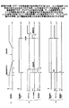
次に、図6を用いて実施の形態1のデータ処理装置の動作例について説明する。ここでは、比較のために、従来のデータ処理装置の動作例についても併せて説明する。 Next, an operation example of the data processing apparatus according to the first embodiment will be described with reference to FIG. Here, for comparison, an example of operation of a conventional data processing apparatus will also be described.
図6は、実施の形態1のデータ処理装置の動作例を示す図であり、(a)は電源部16の異常の発生を時系列で示す特性、(b)は従来のデータ処理装置による電源異常フラグ、プログラムの動作の有無、データ退避処理及びデータ展開処理の有無、及び電源保持の有無を時系列で示す特性、(c)は実施の形態1のデータ処理装置による電源異常フラグ、プログラムの動作の有無、及び電源残留電力の利用の有無を時系列で示す特性である。
6A and 6B are diagrams illustrating an operation example of the data processing apparatus according to the first embodiment, in which FIG. 6A is a characteristic showing the occurrence of abnormality in the
「従来のデータ処理装置の動作」
図6(b)に示すように、時刻t=0では、電源異常フラグは"0"、プログラムは動作(オン)状態にあり、データ退避処理は行われておらず(OFF)、電源部6のコンデンサによる電源保持は行われていない(無)。
"Operation of conventional data processing equipment"
As shown in FIG. 6B, at time t = 0, the power supply abnormality flag is “0”, the program is in an operating (ON) state, data saving processing is not performed (OFF), and the power supply unit 6 The power is not held by the capacitor of (no).
図6(a)に示すように、時刻t=t1で電源部6の異常が発生すると、時刻t=t2で電源異常フラグが"1"に設定される。これにより、データ退避処理が実行され(ON)、電源部6のコンデンサによる電源保持が行われる(有)。 As shown in FIG. 6A, when an abnormality occurs in the power supply unit 6 at time t = t1, the power supply abnormality flag is set to “1” at time t = t2. As a result, the data saving process is executed (ON), and the power supply is held by the capacitor of the power supply unit 6 (present).
時刻t=t3でデータ退避処理が終了(OFF)し、さらに時刻t=t4では電源部6のコンデンサによるバックアップが終了する(無)。 At time t = t3, the data saving process ends (OFF), and at time t = t4, the backup by the capacitor of the power supply unit 6 ends (none).
時刻t=t5では、電源部6の電圧値がCPU1、レジスタ1A、キャッシュメモリ2、及びメインメモリ4の動作電圧を下回り、時刻t=t6では電源部6の電圧値が略零となる。
At time t = t5, the voltage value of the power supply unit 6 falls below the operating voltage of the
その後、電源部6の交換及び電源の再投入により時刻t=t7から電源部6の電圧値が徐々に上昇される。 Thereafter, the voltage value of the power supply unit 6 is gradually increased from time t = t7 by replacing the power supply unit 6 and turning on the power again.
時刻t=t8において再起動がかけられると、CPU1によって電源異常フラグが"0"に設定され、退避されていたデータの展開処理が実行される(ON)。
When restarting is performed at time t = t8, the power failure flag is set to “0” by the
時刻t=t9でデータの展開処理が終了すると(OFF)、時刻t=t10でCPU1が展開されたデータを用いてジョブを継続する。
When the data expansion process ends at time t = t9 (OFF), the job is continued using the data expanded by the
以上で、従来のデータ処理装置による処理が終了する。なお、時刻t=t2〜t4は、例えば、数秒から数十秒程度である。 This is the end of the processing by the conventional data processing apparatus. The time t = t2 to t4 is, for example, about several seconds to several tens of seconds.
このように、従来のデータ処理装置では、データ退避処理及びデータ展開処理が必要なため、再起動を迅速に行うことができず、また、データ退避処理を行うための電力供給源が必要であった。このような電力供給源は、大容量のコンデンサとして電源部6内に実装されていたため、従来のデータ処理装置は、小型化が困難で、コストも嵩んでいた。 As described above, since the conventional data processing apparatus requires the data saving process and the data expansion process, the restart cannot be performed quickly, and a power supply source for performing the data saving process is necessary. It was. Since such a power supply source is mounted in the power supply unit 6 as a large-capacity capacitor, it is difficult to reduce the size and cost of the conventional data processing device.
「実施の形態1のデータ処理装置の動作」
図6(c)に示すように、時刻t=0では、電源異常フラグは"0"、プログラムは動作(オン)状態にあり、電源部16の残留電力は使用されていない(無)。
“Operation of Data Processing Device of
As shown in FIG. 6C, at time t = 0, the power supply abnormality flag is “0”, the program is in an operating (ON) state, and the remaining power of the
図6(a)に示すように、時刻t=t1で電源部6の異常が発生すると、時刻t=t2で電源異常フラグが"1"に設定される。これにより、プログラムが停止される(OFF)。なお、プログラムの停止とともに、データ処理装置の全ての処理が停止される。 As shown in FIG. 6A, when an abnormality occurs in the power supply unit 6 at time t = t1, the power supply abnormality flag is set to “1” at time t = t2. As a result, the program is stopped (OFF). Note that all processing of the data processing apparatus is stopped along with the stop of the program.
また、時刻t=t2からの数ミリ秒程度の間は、プログラムの停止やデータ処理装置の全ての処理の停止を行うために、電源部16の残留電力が利用される。
In addition, during the period of several milliseconds from time t = t2, the remaining power of the
その後、電源交換が行われ、時刻t=t8にデータ処理装置の再起動がかけられると、CPU10は、電源部16の異常発生時のステップから再開する。
Thereafter, the power supply is exchanged, and when the data processing apparatus is restarted at time t = t8, the
以上のように、実施の形態1のデータ処理装置は、電源部16に異常が発生し、電圧値が低下した場合でも、CPU10は、レジスタ10A、キャッシュメモリ12、及びメインメモリ14へのアクセスを禁止し、全ての処理を停止させるだけである。
As described above, in the data processing apparatus according to the first embodiment, even when an abnormality occurs in the
レジスタ10A、キャッシュメモリ12、及びメインメモリ14は不揮発性のメモリであるため、従来のようなデータ退避処理を実行しなくても、各メモリのデータは保存される。
Since the
このため、実施の形態1のデータ処理装置によれば、電源部16の電力供給系に異常が発生した場合でも、従来のようなデータ退避処理は不要である。
For this reason, according to the data processing apparatus of the first embodiment, even when an abnormality occurs in the power supply system of the
また、再起動がかけられた後においても、従来のデータ処理装置のように、HDD5に退避させたデータをレジスタ1A、キャッシュメモリ2、及びメインメモリ4に展開させる必要がない。
Further, even after the restart, it is not necessary to expand the data saved in the
CPU10は、再起動がかけられた後には、レジスタ10A、キャッシュメモリ12、及びメインメモリ14の各々で保持されたデータを用いてジョブ継続を行う。
After restarting, the
このため、電源部16の電力供給系に異常が発生した場合でも、短時間に復旧し、ジョブ継続を実現することができる。このように早期に復旧が可能なため、早期にコンピュータ装置の使用が可能となる。これは、特に、システムの利用者が多い機関等、早期復旧が求められるデータ処理装置において有益である。
For this reason, even if an abnormality occurs in the power supply system of the
また、上述のように、電源部16には、レジスタ10A、キャッシュメモリ12、及びメインメモリ14の長時間の電源保持は必要ないため、大容量のコンデンサを電源部16内に備える必要がない。
Further, as described above, the
このため、電源部16の小型化を図ることができ、これにより、データ処理装置も小型化される。また、データ展開処理のコストダウンを図ることができる。
For this reason, the
また、従来のデータ処理装置では、バックアップ用のコンデンサ自体に短絡等の異常が生じた場合には、データの退避処理を行うことができない。 Further, in the conventional data processing apparatus, when an abnormality such as a short circuit occurs in the backup capacitor itself, the data saving process cannot be performed.
これに対して、実施の形態1のデータ処理装置では、レジスタ10A、キャッシュメモリ12、及びメインメモリ14の全てが不揮発性のメモリであるため、データの退避処理を行う必要が無く、データを保存するため、信頼性の高いデータ処理装置を提供することができる。
On the other hand, in the data processing apparatus of the first embodiment, since all of the
また、以上では、CPU10は、再起動がかけられた際に、電源部16の異常の発生時に実行していたプログラムを電源部16の異常発生時のステップから再開する形態について説明したが、異常発生時のステップよりも1ステップ前のステップから再開してもよい。
In the above description, the
このように、実施の形態1によれば、電源部16に電源保持用の大容量のコンデンサを設ける必要がないため、安価でデータ処理装置を提供することができる。
As described above, according to the first embodiment, since it is not necessary to provide the
また、以上では、レジスタ10A、キャッシュメモリ12、及びメインメモリ14の全てが不揮発性のメモリであり、電源保持用のコンデンサを有しない形態について説明した。
In the above description, the
しかしながら、データ退避処理とデータ展開処理を不要にしてデータ展開処理の復旧を急ぐという観点からは、レジスタ10A、キャッシュメモリ12、及びメインメモリ14のすべてに電源保持用のコンデンサが接続されていてもよい。また、同様に、レジスタ10A、キャッシュメモリ12、及びメインメモリ14のうちのいずれかが不揮発性のメモリであり、揮発性メモリのものにバックアップ用電源が接続されていてもよい。
However, from the viewpoint of urgent recovery of the data expansion process by eliminating the data saving process and the data expansion process, even if a power holding capacitor is connected to all of the
[実施の形態2]
図7は、実施の形態2のデータ処理装置の構成を示す図である。実施の形態2のデータ処理装置は、メインメモリ24が揮発性のメモリであり、バックアップ用電源(バッテリバックアップ等)7が接続されている点が実施の形態1のデータ処理装置と異なる。その他の構成は、実施の形態1のデータ処理装置と同一であるため、同一の構成要素には同一符号を付し、その説明を省略する。
[Embodiment 2]
FIG. 7 is a diagram illustrating the configuration of the data processing apparatus according to the second embodiment. The data processing apparatus according to the second embodiment is different from the data processing apparatus according to the first embodiment in that the main memory 24 is a volatile memory and a backup power source (battery backup or the like) 7 is connected. Since other configurations are the same as those of the data processing apparatus of the first embodiment, the same components are denoted by the same reference numerals, and description thereof is omitted.
実施の形態2のデータ処理装置においても、電源部16の異常が発生した場合には、メインメモリ24のデータはバックアップ用電源7によって保持される。
Also in the data processing apparatus of the second embodiment, when an abnormality occurs in the
このため、実施の形態1と同様に、CPU10が全ての処理を停止することにより、データ退避処理は不要であり、再起動をかけるまでの時間が大幅に短縮化され、短時間に復旧し、ジョブ継続を実現することができる。
For this reason, as in the first embodiment, the
以上、本発明の例示的な実施の形態のデータ処理装置について説明したが、本発明は、具体的に開示された実施の形態に限定されるものではなく、特許請求の範囲から逸脱することなく、種々の変形や変更が可能である。 The data processing apparatus according to the exemplary embodiment of the present invention has been described above, but the present invention is not limited to the specifically disclosed embodiment, and does not depart from the scope of the claims. Various modifications and changes are possible.
以上の実施の形態1、2に関し、さらに以下の付記を開示する。
(付記1)
レジスタを有するCPUと、
キャッシュメモリと、
前記キャッシュメモリとデータの授受を行うメインメモリと、
前記キャッシュメモリと前記メインメモリとの間のデータの授受を制御する制御部と、
前記レジスタ、前記キャッシュメモリ、及び前記メインメモリに電源供給を行う電源部と
を含み、
前記レジスタ、前記キャッシュメモリ、及び前記メインメモリの各々は、前記電源部からの電源供給がなくとも記憶しているデータの内容が消失しない構成であり、
さらに前記制御部は、前記電源部の異常時に、前記CPUからの、前記レジスタ、前記キャッシュメモリ、及び前記メインメモリへのアクセスを停止する
ことを特徴とするデータ処理装置。
(付記2)
前記制御部は、前記電源部の異常発生後に前記電源部が復旧されると、前記CPUに前記レジスタ、前記キャッシュメモリ、及び前記メインメモリの各々に保持されたデータを用いて処理を再開させる処理を行う、付記1に記載のデータ処理装置。
(付記3)
前記CPUは、前記電源部の異常時に、前記CPUの制御信号、又は前記CPUのアドレス信号を前記レジスタ内に保存する、付記1または付記2のいずれか一項に記載のデータ処理装置。
(付記4)
前記CPUは、前記電源部の異常発生後に前記電源部が復旧されると、前記電源部の異常の発生時に実行していたプログラムを前記電源部の異常発生時のステップ、又は、前記異常発生時のステップよりも1ステップ前のステップから再開する、付記1乃至3に記載のデータ処理装置。
(付記5)
前記レジスタ、前記キャッシュメモリ、及び前記メインメモリの各々は、不揮発性メモリであることを特徴とする付記1乃至4に記載のデータ処理装置。
(付記6)
前記レジスタ、前記キャッシュメモリ、及び前記メインメモリの各々は、前記電源部の異常時にバックアップ用電源から電力が供給される揮発性メモリであることを特徴とする付記1乃至4に記載のデータ処理装置。
The following additional notes are further disclosed with respect to the first and second embodiments.
(Appendix 1)
A CPU having a register;
Cache memory,
A main memory for transferring data to and from the cache memory;
A control unit that controls data exchange between the cache memory and the main memory;
A power supply unit for supplying power to the register, the cache memory, and the main memory,
Each of the register, the cache memory, and the main memory has a configuration in which the contents of stored data are not lost even without power supply from the power supply unit.
Further, the control unit stops access to the register, the cache memory, and the main memory from the CPU when the power supply unit is abnormal.
(Appendix 2)
The control unit causes the CPU to resume processing using data held in each of the register, the cache memory, and the main memory when the power unit is restored after an abnormality occurs in the power unit. The data processing device according to
(Appendix 3)
3. The data processing apparatus according to
(Appendix 4)
The CPU, when the power supply unit is restored after the occurrence of an abnormality in the power supply unit, executes a program executed when the abnormality occurs in the power supply unit, or when the abnormality occurs in the
(Appendix 5)
Each of the register, the cache memory, and the main memory is a non-volatile memory.
(Appendix 6)
Each of the register, the cache memory, and the main memory is a volatile memory to which power is supplied from a backup power supply when the power supply unit is abnormal, The data processing device according to any one of
3 制御部
5 HDD
1、10 CPU
1A、10A レジスタ
2、12 キャッシュメモリ
4、14、24 メインメモリ
6、16 電源部
7 バックアップ用電源
3
1, 10 CPU
1A,
Claims (2)
キャッシュメモリと、
前記キャッシュメモリとデータの授受を行うメインメモリと、
前記キャッシュメモリと前記メインメモリとの間のデータの授受を制御する制御部と、
前記レジスタ、前記キャッシュメモリ、及び前記メインメモリに電源供給を行う電源部と
を含み、
前記レジスタ及び前記キャッシュメモリは、不揮発性メモリであり、前記メインメモリは、不揮発性メモリ、又は、前記電源部の異常時にバックアップ用電源から電力が供給される揮発性メモリであり、
さらに前記制御部は、前記CPUが設定する電源異常フラグが前記電源部の異常を表す時に、前記CPUからの、前記レジスタ、前記キャッシュメモリ、及び前記メインメモリへのアクセスを停止し、前記電源部の異常発生後に前記電源部が復旧して電源異常フラグが前記電源部の異常を表さなくなると、前記CPUに前記レジスタ、前記キャッシュメモリ、及び前記メインメモリの各々に保持されたデータを用いて処理を再開させる処理を行う
ことを特徴とするデータ処理装置。 A CPU having a register;
Cache memory,
A main memory for transferring data to and from the cache memory;
A control unit that controls data exchange between the cache memory and the main memory;
A power supply unit for supplying power to the register, the cache memory, and the main memory,
The register and the cache memory are non-volatile memories, and the main memory is a non-volatile memory or a volatile memory to which power is supplied from a backup power supply when the power supply unit is abnormal,
Further, the control unit stops access to the register, the cache memory, and the main memory from the CPU when a power supply abnormality flag set by the CPU indicates an abnormality of the power supply unit, and the power supply unit When the power supply unit recovers after the occurrence of an abnormality and the power supply abnormality flag does not represent the abnormality of the power supply unit , the CPU uses the data held in each of the register, the cache memory, and the main memory. A data processing apparatus that performs processing for resuming processing.
Priority Applications (4)
| Application Number | Priority Date | Filing Date | Title |
|---|---|---|---|
| JP2008222243A JP5581577B2 (en) | 2008-08-29 | 2008-08-29 | Data processing device |
| TW098122014A TWI456385B (en) | 2008-08-29 | 2009-06-30 | Data processing apparatus |
| US12/495,991 US8135971B2 (en) | 2008-08-29 | 2009-07-01 | Data processing apparatus |
| CN200910160920A CN101661435A (en) | 2008-08-29 | 2009-07-24 | Data processing apparatus |
Applications Claiming Priority (1)
| Application Number | Priority Date | Filing Date | Title |
|---|---|---|---|
| JP2008222243A JP5581577B2 (en) | 2008-08-29 | 2008-08-29 | Data processing device |
Related Child Applications (1)
| Application Number | Title | Priority Date | Filing Date |
|---|---|---|---|
| JP2014010189A Division JP2014089763A (en) | 2014-01-23 | 2014-01-23 | Data processing device |
Publications (2)
| Publication Number | Publication Date |
|---|---|
| JP2010055531A JP2010055531A (en) | 2010-03-11 |
| JP5581577B2 true JP5581577B2 (en) | 2014-09-03 |
Family
ID=41727063
Family Applications (1)
| Application Number | Title | Priority Date | Filing Date |
|---|---|---|---|
| JP2008222243A Expired - Fee Related JP5581577B2 (en) | 2008-08-29 | 2008-08-29 | Data processing device |
Country Status (4)
| Country | Link |
|---|---|
| US (1) | US8135971B2 (en) |
| JP (1) | JP5581577B2 (en) |
| CN (1) | CN101661435A (en) |
| TW (1) | TWI456385B (en) |
Families Citing this family (8)
| Publication number | Priority date | Publication date | Assignee | Title |
|---|---|---|---|---|
| TW201229738A (en) * | 2011-01-11 | 2012-07-16 | Hon Hai Prec Ind Co Ltd | Power supply system |
| JP2012203583A (en) * | 2011-03-24 | 2012-10-22 | Toshiba Corp | Information processing apparatus and program |
| CN103946812B (en) | 2011-09-30 | 2017-06-09 | 英特尔公司 | Apparatus and method for realizing multi-level memory hierarchy |
| CN103946811B (en) * | 2011-09-30 | 2017-08-11 | 英特尔公司 | Apparatus and method for realizing the multi-level store hierarchy with different operation modes |
| EP2761480A4 (en) | 2011-09-30 | 2015-06-24 | Intel Corp | Apparatus and method for implementing a multi-level memory hierarchy over common memory channels |
| US9342453B2 (en) | 2011-09-30 | 2016-05-17 | Intel Corporation | Memory channel that supports near memory and far memory access |
| GB201200219D0 (en) * | 2012-01-09 | 2012-02-22 | Calder Martin | A clock signal generator for a digital circuit |
| JP2013243565A (en) * | 2012-05-22 | 2013-12-05 | Semiconductor Energy Lab Co Ltd | Semiconductor device and method of driving the same |
Family Cites Families (16)
| Publication number | Priority date | Publication date | Assignee | Title |
|---|---|---|---|---|
| JPH0670769B2 (en) * | 1987-04-24 | 1994-09-07 | 株式会社日立製作所 | Power control method |
| JPH025120A (en) * | 1988-06-22 | 1990-01-10 | Mitsubishi Electric Corp | Abnormality detector for power supply voltage detecting input |
| US5511183A (en) | 1992-05-12 | 1996-04-23 | Fujitsu Limited | Non-volatile memory controlling apparatus and applications of the same to electronic computer peripheral equipments |
| JPH06251570A (en) | 1993-02-26 | 1994-09-09 | Fujitsu Ltd | Library device |
| JPH07146820A (en) * | 1993-04-08 | 1995-06-06 | Hitachi Ltd | Control method for flash memory and information processor using the same |
| JPH07253935A (en) | 1994-03-15 | 1995-10-03 | Toshiba Corp | Data protection device for computer |
| US5553238A (en) | 1995-01-19 | 1996-09-03 | Hewlett-Packard Company | Powerfail durable NVRAM testing |
| JP3798476B2 (en) * | 1996-08-30 | 2006-07-19 | 株式会社東芝 | Computer system and cache memory power-down control method in the system |
| GB2379538B (en) * | 2000-06-23 | 2005-01-12 | Intel Corp | Non-volatile cache |
| US7028154B2 (en) | 2002-06-18 | 2006-04-11 | Hewlett-Packard Development Company, L.P. | Procedure to reduce copy time for data backup from short-term to long-term memory |
| US7131011B2 (en) * | 2002-10-30 | 2006-10-31 | Microsoft Corporation | System and method for preserving state data of a personal computer in a standby state in the event of an AC power failure |
| JP2004164185A (en) * | 2002-11-12 | 2004-06-10 | Sony Corp | Computer device comprising volatile system memory and nonvolatile semiconductor memory |
| CN1853151A (en) * | 2003-09-16 | 2006-10-25 | 皇家飞利浦电子股份有限公司 | Power saving operation of an apparatus with a cache memory |
| JP2005115857A (en) | 2003-10-10 | 2005-04-28 | Sony Corp | File storage device |
| US20060136765A1 (en) * | 2004-12-03 | 2006-06-22 | Poisner David L | Prevention of data loss due to power failure |
| TWI352906B (en) * | 2005-11-15 | 2011-11-21 | Montalvo Systems Inc | Method, microprocessor system, medium, memory elem |
-
2008
- 2008-08-29 JP JP2008222243A patent/JP5581577B2/en not_active Expired - Fee Related
-
2009
- 2009-06-30 TW TW098122014A patent/TWI456385B/en not_active IP Right Cessation
- 2009-07-01 US US12/495,991 patent/US8135971B2/en not_active Expired - Fee Related
- 2009-07-24 CN CN200910160920A patent/CN101661435A/en active Pending
Also Published As
| Publication number | Publication date |
|---|---|
| US20100058094A1 (en) | 2010-03-04 |
| US8135971B2 (en) | 2012-03-13 |
| TW201009561A (en) | 2010-03-01 |
| TWI456385B (en) | 2014-10-11 |
| JP2010055531A (en) | 2010-03-11 |
| CN101661435A (en) | 2010-03-03 |
Similar Documents
| Publication | Publication Date | Title |
|---|---|---|
| JP5581577B2 (en) | Data processing device | |
| US8078908B2 (en) | Data storage device and method | |
| US8352770B2 (en) | Method, system and apparatus for low-power storage of processor context information | |
| US7971014B2 (en) | Information processing apparatus and data recovering method | |
| JP5321866B2 (en) | Computer system | |
| JP2006313407A (en) | Dirty data processing method, dirty data processor and dirty data processing program | |
| JP2010160654A (en) | Cache memory backup device, method and program | |
| CN111880636B (en) | Power-off protection method and related device for storage array | |
| JP2009104369A (en) | Disk sub-system | |
| JP2007087269A (en) | Software update system, update method and program | |
| JP2010117752A (en) | Data holding method of electronic equipment and electronic equipment | |
| JP2014089763A (en) | Data processing device | |
| JP2007328438A (en) | Information processor, its data backup, and restoration method | |
| JP2008059007A (en) | Semiconductor storage device | |
| US20130073792A1 (en) | Electronic apparatus using nand flash and memory management method thereof | |
| KR101076395B1 (en) | Method of Controlling Power in an Video Recording Apparatus for Vehicles | |
| JP2006318105A (en) | Monitoring system | |
| JP4098400B2 (en) | Semiconductor disk device | |
| JP5161600B2 (en) | Information processing apparatus and data recovery method | |
| JP2000081921A (en) | Computer system | |
| JP2002268955A (en) | Method and device of memory backup | |
| JPH0744982A (en) | Data recording/reproducing device and method for controlling data write | |
| JP2009054116A (en) | Memory system and information processor | |
| WO2022038857A1 (en) | Terminal device | |
| JP2007148684A (en) | Memory checking apparatus, mobile terminal, cellphone, and method for checking its memory |
Legal Events
| Date | Code | Title | Description |
|---|---|---|---|
| A621 | Written request for application examination |
Free format text: JAPANESE INTERMEDIATE CODE: A621 Effective date: 20110513 |
|
| A977 | Report on retrieval |
Free format text: JAPANESE INTERMEDIATE CODE: A971007 Effective date: 20120606 |
|
| A131 | Notification of reasons for refusal |
Free format text: JAPANESE INTERMEDIATE CODE: A131 Effective date: 20120612 |
|
| A521 | Written amendment |
Free format text: JAPANESE INTERMEDIATE CODE: A523 Effective date: 20120810 |
|
| A131 | Notification of reasons for refusal |
Free format text: JAPANESE INTERMEDIATE CODE: A131 Effective date: 20130326 |
|
| A521 | Written amendment |
Free format text: JAPANESE INTERMEDIATE CODE: A523 Effective date: 20130524 |
|
| A131 | Notification of reasons for refusal |
Free format text: JAPANESE INTERMEDIATE CODE: A131 Effective date: 20131203 |
|
| A521 | Written amendment |
Free format text: JAPANESE INTERMEDIATE CODE: A523 Effective date: 20140123 |
|
| TRDD | Decision of grant or rejection written | ||
| A01 | Written decision to grant a patent or to grant a registration (utility model) |
Free format text: JAPANESE INTERMEDIATE CODE: A01 Effective date: 20140617 |
|
| A61 | First payment of annual fees (during grant procedure) |
Free format text: JAPANESE INTERMEDIATE CODE: A61 Effective date: 20140630 |
|
| R150 | Certificate of patent or registration of utility model |
Ref document number: 5581577 Country of ref document: JP Free format text: JAPANESE INTERMEDIATE CODE: R150 |
|
| LAPS | Cancellation because of no payment of annual fees |