JP5578915B2 - Solid-state imaging device and driving method thereof - Google Patents
Solid-state imaging device and driving method thereof Download PDFInfo
- Publication number
- JP5578915B2 JP5578915B2 JP2010085471A JP2010085471A JP5578915B2 JP 5578915 B2 JP5578915 B2 JP 5578915B2 JP 2010085471 A JP2010085471 A JP 2010085471A JP 2010085471 A JP2010085471 A JP 2010085471A JP 5578915 B2 JP5578915 B2 JP 5578915B2
- Authority
- JP
- Japan
- Prior art keywords
- row
- counter
- pixel
- reset
- field
- Prior art date
- Legal status (The legal status is an assumption and is not a legal conclusion. Google has not performed a legal analysis and makes no representation as to the accuracy of the status listed.)
- Expired - Fee Related
Links
Images


Classifications
-
- H—ELECTRICITY
- H04—ELECTRIC COMMUNICATION TECHNIQUE
- H04N—PICTORIAL COMMUNICATION, e.g. TELEVISION
- H04N25/00—Circuitry of solid-state image sensors [SSIS]; Control thereof
- H04N25/50—Control of the SSIS exposure
- H04N25/53—Control of the integration time
- H04N25/531—Control of the integration time by controlling rolling shutters in CMOS SSIS
-
- H—ELECTRICITY
- H04—ELECTRIC COMMUNICATION TECHNIQUE
- H04N—PICTORIAL COMMUNICATION, e.g. TELEVISION
- H04N25/00—Circuitry of solid-state image sensors [SSIS]; Control thereof
- H04N25/70—SSIS architectures; Circuits associated therewith
- H04N25/76—Addressed sensors, e.g. MOS or CMOS sensors
- H04N25/767—Horizontal readout lines, multiplexers or registers
Description
本発明は、固体撮像装置及びその駆動方法に関する。 The present invention relates to a solid-state imaging device and a driving method thereof.
近年、数百万画素を超える固体撮像装置がデジタルカメラに使用されるようになり、高精彩な静止画像を撮影することが可能となっている。動画撮影においても、滑らかな動画を撮影するために、固体撮像装置に高フレームレートで画像を読み出したいという要請がある。高フレームレートで読み出す場合、固体撮像装置の画素部の光電変換素子の、1フレームあたりの蓄積時間が短くなるので、特に暗い被写体からは充分な露光量が得られないという問題がある。限られた露光時間で、充分な露光量を得るための手段として、CCD型の撮像素子において、2つの間引きモードを用いる方法が下記の特許文献1に記載されている。特許文献1によると、2つのモードのうち一方は、蓄積時間が1垂直走査期間以内の場合に、電子シャッターを用いて細かな蓄積時間制御を行うモードである。また、他方のモードは、蓄積時間が1垂直走査期間を超える場合に、電子シャッターは使用せず蓄積時間を固定化し、被写体の明るさに応じて信号増幅手段の増幅率を変化させるモードである。
In recent years, solid-state imaging devices having millions of pixels have been used for digital cameras, and high-definition still images can be taken. Even in moving image shooting, there is a demand for a solid-state imaging device to read an image at a high frame rate in order to shoot a smooth moving image. In the case of reading at a high frame rate, since the accumulation time per frame of the photoelectric conversion element of the pixel portion of the solid-state imaging device is shortened, there is a problem that a sufficient exposure amount cannot be obtained particularly from a dark subject. As a means for obtaining a sufficient exposure amount with a limited exposure time, a method using two thinning modes in a CCD type image sensor is described in
特許文献1に開示された固体撮像装置では、2つの間引き読み出しモードを切り替えて行う為、切り替えたタイミングを境目にして間引きの仕方が変化する。つまり短秒(例えば1/30秒)蓄積の際は3行毎に2行を読み飛ばすのに対して、長秒(例えば1/15秒)では3行毎に1行だけを読み飛ばす。これは撮影シーンによっては視認され、違和感をもたらす。また、特許文献1では、蓄積時間1/30〜1/15秒のシーンでは、回路の増幅率を変化させる。増幅率が変化すると回路のノイズも変化する。従って、特に暗い被写体を撮影している際、蓄積時間の切り替わりの前後で画質が変化する。これもシーンによって視認され、違和感をもたらす。
In the solid-state imaging device disclosed in
本発明の目的は、動画撮影における画質を向上させることができる固体撮像装置及びその制御方法を提供することである。 An object of the present invention is to provide a solid-state imaging device capable of improving the image quality in moving image shooting and a control method thereof.
本発明の固体撮像装置は、光電変換により画素信号を生成する複数の画素が2次元行列状に配列された画素部と、前記画素部の行を選択する画素駆動部と、を有し、前記画素駆動部は、第1のフィールドで読み出される前記画素部の行を走査して前記第1のフィールドで読み出される画素の画素信号を順次リセットし、その後、第2のフィールドで読み出される前記画素部の行を走査して前記第2のフィールドで読み出される画素の画素信号を順次リセットし、その後、前記第1のフィールドの画素の画素信号を順次読み出し、その後、前記第2のフィールドの画素の画素信号を順次読み出す第1の動作モードと、前記第1のフィールドで読み出される前記画素部の行を走査して前記第1のフィールドで読み出される画素の画素信号を順次リセットし、その後、前記第1のフィールドの画素の画素信号を順次読み出し、その後、前記第2のフィールドで読み出される前記画素部の行を走査して前記第2のフィールドで読み出される画素の画素信号を順次リセットし、その後、前記第2のフィールドの画素の画素信号を順次読み出す第2の動作モードとを備え、前記第2の動作モードに引き続き前記第1の動作モードが行われる際、前記第2の動作モードにおける前記第2のフィールドの画素の画素信号の読み出しの走査開始は、前記第1の動作モードにおける前記第1のフィールドの画素の画素信号のリセットの走査開始の後、かつ前記第1の動作モードにおける前記第2のフィールドの画素の画素信号のリセットの走査開始の前に行われることを特徴とする。 The solid-state imaging device of the present invention includes a pixel unit in which a plurality of pixels that generate pixel signals by photoelectric conversion are arranged in a two-dimensional matrix, and a pixel driving unit that selects a row of the pixel unit, The pixel driver scans the row of the pixel portion read in the first field, sequentially resets the pixel signals of the pixels read in the first field, and then reads the pixel portion in the second field And sequentially resets the pixel signals of the pixels read out in the second field, then sequentially reads out the pixel signals of the pixels in the first field, and then the pixels of the pixels in the second field a first operation mode of sequentially reading signals, the first scanning line of the pixel portion to be read in the field of pixels read by the first field pixel signals sequentially Li Then, the pixel signals of the pixels in the first field are sequentially read out, and then the pixels of the pixels read out in the second field are scanned by scanning the row of the pixel portion read out in the second field. A second operation mode for sequentially resetting signals and then sequentially reading out pixel signals of the pixels in the second field, and when the first operation mode is performed following the second operation mode, The scanning start of the reading of the pixel signal of the pixel in the second field in the second operation mode is performed after the scanning start of the reset of the pixel signal of the pixel in the first field in the first operation mode, and It is performed before the start of scanning for resetting the pixel signal of the pixel in the second field in the first operation mode .
動画撮影における画質を向上させることができる。The image quality in moving image shooting can be improved.
(第1の実施形態)
図1(A)は、本発明の第1の実施形態に係る固体撮像装置の構成例を示すブロック図である。固体撮像素子1は、画素部11及び画素駆動部12L,12Rを有する。画素部11は、行と列の2次元行列状に配列された複数の画素で構成される。画素駆動部12L,12Rは、画素を駆動する信号、すなわちフォトダイオードに蓄積された電荷を転送するための転送信号や、行列の中から特定の行の画素を選択するための行選択信号などを奇数行と偶数行のそれぞれに対して生成する。画素部11は、各々が光電変換素子(フォトダイオード)の光電変換により画素信号を生成する複数の画素を含む。各画素は、例えば光電変換素子の他に光電変換素子で蓄積された電荷に基づく電圧信号を出力する増幅部を有する、増幅型の画素が考えられる。固体撮像素子1は、奇数行と偶数行の行選択信号を保持するための選択記憶部13L,13R、行カウント値S15に対応する1行を選択する行アドレスデコーダ14L,14R、行アドレス生成部15、タイミング生成部16、行カウンタ制御部18を有する。行アドレス生成部15は、読み出し行カウンタ151、リセット行カウンタA(152)、リセット行カウンタB(153)及びセレクタ150を有する。セレクタ150は、3つの行カウンタ151〜153が出力する行アドレスの内、1つを選択して行カウント値S15として出力する。読み出し行カウンタ151は、画素部11の読み出しの行アドレスを生成する。第1のリセット行カウンタA(152)は、画素部11の奇数フィールド(第1のフィールド)でリセットする行を示す行アドレスを生成する。第2のリセット行カウンタB(153)は、画素部11の偶数フィールド(第2のフィールド)でリセットする行を示す行アドレスを生成する。奇数フィールド及び偶数フィールドは1フレームを構成する。セレクタ150は、読み出し行カウンタ151、リセット行カウンタA(152)及びリセット行カウンタB(153)により生成される行アドレスのうちの1つの行アドレスを選択する。行カウンタ制御部18は、外部のCPUからの通信信号19、垂直同期信号20、水平同期信号21に基づき、3つの行カウンタ151〜153のそれぞれに対し、カウンタスタートパルス等のカウンタ制御信号S1811〜S1813を出力する。行カウンタ制御部18は、行カウンタ151〜153を制御する。行アドレスデコーダ14L,14Rは、セレクタ150によって選択された行アドレスをデコードする。選択記憶部13L,13Rは、行アドレスデコーダ14L,14Rの出力ビットを入力してその状態を記憶する。画素駆動部12L,12Rは、選択記憶部13L,13Rに記憶された出力ビットに対応する行選択信号を出力する。タイミング生成部16は、外部のCPUからの通信信号19、垂直同期信号20、水平同期信号21に基づき、3つの行カウンタ151〜153のうちの1つを選択する行アドレス生成部選択信号S1610を生成する。さらに、タイミング生成部16は、選択記憶部13L,13Rを制御する奇数行と偶数行共通の記憶部制御信号S162と、画素駆動部12L,12Rを制御する画素駆動信号S163L,S163Rを生成する。第1の画素駆動部12Lは、セレクタ150により選択された行アドレスに対応する画素部11の奇数行を選択する。第2の画素駆動部12Rは、セレクタ150により選択された行アドレスに対応する画素部11の偶数行を選択する。第1及び第2の画素駆動部12L、12Rは、対応する選択記憶部13L、13Rの出力と、タイミング生成部16から供給される不図示の信号との論理和や論理積によって画素の動作を制御する構成になっている。固体撮像素子1、タイミング生成部16、行カウンタ制御部18は同一半導体上に集積されていても、されていなくてもかまわない。
(First embodiment)
FIG. 1A is a block diagram illustrating a configuration example of the solid-state imaging device according to the first embodiment of the present invention. The solid-
図1(B)は、図1(A)の選択記憶部13L,13Rの構成例を示す回路図である。選択記憶部13L,13Rは、それぞれ画素部11の1/2の行数の行選択記憶回路131を含んで構成される。行選択記憶回路131は、Dラッチ135と、論理積(AND)回路136と、SRラッチ137を含んで構成される。行選択記憶回路131には、行アドレスデコーダ14L,14Rが出力するデコード信号132の1ビットと、記憶部制御信号S162である書き込み許可信号wen_rd、SRラッチ137の消去信号clear_sh及びセット信号wen_shが入力される。書き込み許可信号wen_rdは、Dラッチ135のクロック端子(CK)に入力され、データ端子(D)には、デコード信号132の内の1ビットが入力され、そのDラッチ135のQ出力信号は、画素信号を転送する行の行選択信号Lrd(133)となる。消去信号clear_shは、SRラッチ137のリセット端子(R)に入力される。AND回路136は、セット信号wen_sh及びデコード信号132の内の1ビットとが入力され、その論理積を、SRラッチ137のセット端子(S)に出力する。SRラッチ137のQ出力信号は、画素をリセットする行の行選択信号Lsh(134)となる。選択記憶部13L、13Rでそれぞれ生成された、画素信号を転送する行の行選択信号Lrd(133)と、画素をリセットする行の行選択信号Lsh(134)は、画素駆動部12L,12Rに入力される。これにより、行アドレスデコーダ14L,14Rにより選択された画素部11の対応する行の画素信号の転送、及びリセットが可能となる。
FIG. 1B is a circuit diagram illustrating a configuration example of the
図2(A)及び(B)は、図1(A)の行カウンタ制御部18と、タイミング生成部16と、選択記憶部13L,13Rの動作の概要を示すタイミング図である。図2(A)は外部からの入力信号の入力タイミングを示す。CPUからの通信信号19は、垂直同期信号(VD)20として入力されるパルス201に先立って、次の垂直同期期間203に実施する動作の通信信号191を含む。垂直同期期間203は、水平同期信号(HD)21として入力される複数の水平同期パルス211により構成される。
2A and 2B are timing charts showing an outline of operations of the row counter control unit 18, the
図2(B)は、図2(A)の1水平同期期間212における固体撮像装置の駆動方法の概要を示すタイミング図である。1水平同期期間212における動作は、ステート遷移22に示す、期間221〜期間225までの処理期間に大別される。行カウント値S15は、タイミング生成部16の行アドレス生成部選択信号S1610により、期間221では読み出し行カウンタ151の出力信号S151となり、期間222ではリセット行カウンタA(152)の出力信号S152となる。また、行カウント値S15は、その他の期間では、リセット行カウンタB(153)の出力信号S153となる。
FIG. 2B is a timing chart showing an outline of a method for driving the solid-state imaging device in one
最初に、1水平同期期間212における行の画素信号の転送動作について述べる。まず、期間221にて、タイミング生成部16は、書き込み許可信号wen_rdのパルスを生成する。読み出し行カウンタ151の出力信号S151のデコード信号132はDラッチ135にてラッチされる。ここでは、読み出し行カウンタ151の出力信号S151がL行を選択している例を示しており、画素信号を転送する行の行選択信号Lrd(133)はL行のみはハイレベルに遷移し、その他の行L+1行、N行はローレベルのままである。この時、行カウント値S15は、行アドレスデコーダ14L,14R共通であり、かつ、書き込み許可信号wen_rdも、選択記憶部13L,13Rに共通である。そのため、画素駆動部12L,12Rでは、奇数行のみからなる群のL行と偶数行のみからなる群のL行が選択されることとなる。期間222では、タイミング生成部16により、画素駆動部12Lが制御され、画素部11の奇数行のみからなる群のL行の画素信号が、水平転送部17へ垂直転送される。期間223では、タイミング生成部16により、画素駆動部12Rが制御され、画素部11の偶数行のみからなる群のL行の画素信号が、水平転送部17へ垂直転送される。期間224では、タイミング生成部16の制御により垂直転送された、奇数行と偶数行2つのL行の画素信号が水平転送部17にて水平転送され固体撮像素子1の出力画素信号となる。
First, a transfer operation of pixel signals in a row in one
次に、1水平同期期間212における行の画素信号のリセット動作について述べる。タイミング生成部16は、期間221にて、消去信号clear_shのパルス、期間222と期間223にて、セット信号wen_shのパルスを生成する。ここでは、リセット行カウンタA(152)の出力信号S152がL+1行を選択し、リセット行カウンタB(153)の出力信号S153がN行を選択、1つ前の1水平同期期間212では、L行が選択されていたものとして例を示す。
Next, a reset operation of pixel signals in a row in one
期間221では、消去信号clear_shのパルスにより、全てのSRラッチ137がリセットされ、選択されていたLsh[L]はハイレベルからローレベルに遷移する。期間222では、リセット行カウンタA(152)の出力信号S152の選択したL+1行をデコードしたデコード信号132と、セット信号wen_shとを入力とするAND回路136の出力により、Lst[L+1]がローレベルからハイレベルに遷移する。期間223では、リセット行カウンタB(153)の出力信号S153の選択したN行をデコードしたデコード信号132と、セット信号wen_shとを入力とするAND回路136の出力により、Lst[N]がローレベルからハイレベルに遷移する。この時、行カウント値S15は、行アドレスデコーダ14L,14R共通であり、消去信号clear_sh、セット信号wen_shも、選択記憶部13L,13Rに共通である。そのため、画素駆動部12L,12Rでは、奇数行のL+1行と偶数行のL+1行と、奇数行のN行と偶数行のN行が選択されることとなる。期間224では、タイミング生成部16により、画素駆動部12L,12Rが制御され、選択された、画素部11の奇数行のL+1行と偶数行のL+1行と、奇数行のN行と偶数行のN行の画素リセットを行う。以上により、1水平同期期間212では、隣接する奇数行と偶数行を1組読み出し、2組をリセットすることが出来る構成となっている。
In the
図3は、第1の実施形態による行カウンタ制御部18の構成例を示す図である。以下、露光時間が垂直同期期間より短い場合も長い場合も、連続的に蓄積時間を設定可能な固体撮像装置の駆動方法について述べる。CPU書き込みレジスタR(401)は、CPU19からの通信による読み出し行カウンタ151の制御用のレジスタであり、読み出し走査フラグ、読み出し開始行、読み出し終了行、読み出し行カウンタのカウントアップのステップ値を保持する。CPU書き込みレジスタA(402)は、CPU19からの通信によるリセット行カウンタA(152)の制御用のレジスタであり、リセット走査開始カウント、リセット開始行、リセット終了行、リセット行カウンタAのカウントアップのステップ値を保持する。CPU書き込みレジスタB(403)は、CPU19からの通信によるリセット行カウンタB(153)の制御用のレジスタであり、リセット走査開始カウント、リセット開始行、リセット終了行、リセット行カウンタBのカウントアップのステップ値を保持する。カウンタスタートパルス生成回路R(407)は、CPU書き込みレジスタA(402)の読み出し走査フラグが“0”(走査オフ)でない場合は、垂直同期信号20のタイミングにて読み出し行カウンタ151のスタートパルス415を生成する。
FIG. 3 is a diagram illustrating a configuration example of the row counter control unit 18 according to the first embodiment. Hereinafter, a driving method of the solid-state imaging device capable of setting the accumulation time continuously regardless of whether the exposure time is shorter or longer than the vertical synchronization period will be described. The CPU write register R (401) is a register for controlling the read
VD同期レジスタR(408)は、垂直同期信号20のタイミングにてCPU書き込みレジスタR(401)の読み出し終了行、読み出し行カウンタのカウントアップのステップ値をコピーし保持すると共に信号線416により読み出し行カウンタ151に入力する。VD同期レジスタA(409)は、垂直同期信号20のタイミングにて、CPU書き込みレジスタA(402)のリセット走査開始カウント、リセット開始行、リセット終了行、リセット行カウンタAのカウントアップのステップ値をコピーし保持する。VD同期レジスタB(410)は、垂直同期信号20のタイミングにて、CPU書き込みレジスタB(403)のリセット走査開始カウント、リセット開始行、リセット終了行、リセット行カウンタBのカウントアップのステップ値をコピーし保持する。HDカウンタ414は、垂直同期信号20のタイミングにてリセットされ、水平同期信号21のタイミングでカウントアップするカウンタである。
The VD synchronization register R (408) copies and holds the read end row of the CPU write register R (401) at the timing of the
水平同期信号21が連続して入力され、HDカウンタ414のカウント値が、VD同期レジスタA(409)のリセット走査開始カウントと一致すると、カウンタスタートパルス生成回路A(417)と、HDカウンタ同期レジスタA(419)は次の動作をする。まず、カウンタスタートパルス生成回路A(417)は、リセット行カウンタA(152)のスタートパルス418を生成する。HDカウンタ同期レジスタA(419)は、VD同期レジスタA(409)のリセット終了行、リセット行カウンタAのカウントアップのステップ値をコピーし保持すると共に、リセット行カウンタA(152)にレジスタ値420として出力する。
When the
同様に、HDカウンタ414のカウント値が、VD同期レジスタB(410)のリセット走査開始カウントと一致すると、カウンタスタートパルス生成回路B(421)と、HDカウンタ同期レジスタB(423)は次の動作をする。まず、カウンタスタートパルス生成回路B(421)は、リセット行カウンタB(153)のスタートパルス422を生成する。HDカウンタ同期レジスタB(423)は、VD同期レジスタB(410)のリセット終了行、リセット行カウンタBのカウントアップのステップ値をコピーし保持すると共に、リセット行カウンタB(153)にレジスタ値424として出力する。
Similarly, when the count value of the HD counter 414 matches the reset scanning start count of the VD synchronization register B (410), the counter start pulse generation circuit B (421) and the HD counter synchronization register B (423) perform the next operation. do. First, the counter start pulse generation circuit B (421) generates the
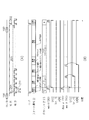
図4は、図3に示した、第1の実施形態による行カウンタ制御部18の動作と、その制御信号出力に基づく、読み出し行カウンタ151、リセット行カウンタA(152)、リセット行カウンタB(153)の動作を示すタイミング図である。図4は、垂直同期信号20により、垂直同期期間500が、期間V0から期間V6へと進む間の各部の動作を示している。CPU書き込みレジスタ値501は、CPU19からの通信により、CPU書き込みレジスタR(401)、CPU書き込みレジスタA(402)、CPU書き込みレジスタB(403)のレジスタに書き込まれるタイミングを示している。
FIG. 4 shows a read
VD同期レジスタ値502は、垂直同期信号20に同期して、VD同期レジスタR(408)、VD同期レジスタA(409)、VD同期レジスタB(410)に、CPU書き込みレジスタ値501の内容がコピーされるタイミングを示している。HDカウンタ値(413)は、HDカウンタ414の出力であるカウンタのカウント値が、カウントアップしていく様子を示しており、そのカウント値は、垂直同期信号20に同期して0にリセットされ、水平同期信号21の入力毎に1ずつカウントアップする。HDカウンタ同期レジスタA値420は、HDカウンタ同期レジスタA(419)の出力であり、HDカウンタ値(413)を参照して、VD同期レジスタA(409)の内容がコピーされるタイミングを示している。HDカウンタ同期レジスタB値424は、HDカウンタ同期レジスタB(423)の出力であり、HDカウンタ値(413)を参照して、VD同期レジスタB(410)の内容がコピーされるタイミングを示している。カウンタスタートパルスR出力(415)は、カウンタスタートパルス生成回路R(407)のパルス出力タイミングを示している。カウンタスタートパルスA出力(418)は、カウンタスタートパルス生成回路A(417)のパルス出力タイミングを示している。カウンタスタートパルスB出力(422)は、カウンタスタートパルス生成回路B(421)のパルス出力タイミングを示している。
The contents of the CPU write register value 501 are copied to the VD synchronization register R (408), the VD synchronization register A (409), and the VD synchronization register B (410) in synchronization with the
行アドレス503は、画素部11の各行に対するアドレスを示しており、行アドレスデコーダ14L,14Rの入力である行カウント値S15との対応を示している。例えば、行アドレス503の1行目は、行アドレスデコーダ14Lのカウント値0に対応し、行アドレス503の2行目は、行アドレスデコーダ14Rのカウント値0に対応することを示している。リセット走査A(505、509)は、リセット行カウンタA(152)によるリセット走査を示している。例えばリセット走査A(505)において、リセット行5051、5053、5055は、行アドレスデコーダ14Lにて選択された行、リセット行5052、5054、5056は、行アドレスデコーダ14Rにて選択された行により構成されることを示す。同様に、リセット走査B(508、512)は、リセット行カウンタB(153)によるリセット走査を示し、読み出し走査506、510、513、514は、読み出し行カウンタ151による読み出し走査を示している。
A row address 503 indicates an address for each row of the pixel unit 11, and indicates a correspondence with a row count value S15 that is an input of the
次に、図4で示す動作を説明する。まず、期間V1においてCPU19からの通信5011により、CPU書き込みレジスタR(401)には、読み出し走査フラグに“0”(走査オフ)を設定し、読み出し走査の禁止を指示する。CPU書き込みレジスタA(402)には、リセット走査開始カウントとしてHDカウンタ値(4131)を書き込み、リセット開始行には“0”、リセット終了行には“n/2−1”、リセット行カウンタAのカウントアップのステップ値には“2”を書き込む。CPU書き込みレジスタB(403)には、リセット走査開始カウントとして、1垂直同期期間にカウントされるHDカウンタ値(413)より大きな値を設定することにより、実質的にリセット走査を禁止できる。
Next, the operation shown in FIG. 4 will be described. First, in a period V1, the CPU write register R (401) is set to “0” (scan off) in the CPU write register R (401) by the
期間V2では、まず通信5011によるCPU書き込みレジスタ値501が、VD同期レジスタR(408)、VD同期レジスタA(409)、VD同期レジスタB(410)にコピーされる(5021)。次に、HDカウンタ値413が、VD同期レジスタA(409)のリセット走査開始カウントであるHDカウンタ値(4131)に一致したとき、VD同期レジスタA(409)が、HDカウンタ同期レジスタA(419)にコピーされる(4201)。さらに、カウンタスタートパルス生成回路A(417)はリセット行カウンタA(152)に対し、スタートパルス4181を生成する。スタートパルス4181を受け、リセット行カウンタA(152)は、リセット走査A(505)を開始する。リセット走査A(505)では、リセット行カウンタA(152)はHDカウンタ同期レジスタA値(4201)を参照する。リセット行カウンタA(152)は、スタートパルス4181の水平同期期間では、リセット開始行である“0”からカウントを開始し画素部11の1行目と2行目をリセットする(5051、5052)。次の水平同期期間では、リセット行カウンタA(152)はカウントアップのステップ値の“2”を加算した値を出力し画素部11の5行目と6行目をリセットする(5053、5054)。以降、水平同期期間毎にステップ値の“2”を加算しリセット終了行まで“n/2−1”リセット走査を行う。
In the period V2, first, the CPU write register value 501 by the
さらに、期間V2では、通信5012により、CPU書き込みレジスタR(401)には、以下の書き込みを行う。読み出し走査フラグに“1”(走査オン)、読み出し開始行には“0”、読み出し終了行には“n/2−1”、読み出し行カウンタのカウントアップのステップ値には“2”を書き込む。CPU書き込みレジスタA(402)には、リセット走査開始カウントとしてHDカウンタ値(4133)を書き込み、リセット開始行には“0”、リセット終了行には“n/2−1”、リセット行カウンタAのカウントアップのステップ値には“2”を書き込む。CPU書き込みレジスタB(403)には、リセット走査開始カウントとしてHDカウンタ値(4132)を書き込み、リセット開始行には“1”、リセット終了行には“n/2”、リセット行カウンタAのカウントアップのステップ値には“2”を書き込む。 Further, in the period V2, the following writing is performed to the CPU write register R (401) by the communication 5012. Write “1” (scan on) to the read scan flag, “0” to the read start row, “n / 2-1” to the read end row, and “2” to the step value for counting up the read row counter. . The CPU write register A (402) is written with the HD counter value (4133) as the reset scanning start count, "0" for the reset start line, "n / 2-1" for the reset end line, and the reset line counter A. “2” is written in the step value of the count up. The CPU write register B (403) is written with the HD counter value (4132) as the reset scanning start count, "1" for the reset start row, "n / 2" for the reset end row, and the count of the reset row counter A. “2” is written to the up step value.
期間V3では、まず通信5012によるCPU書き込みレジスタ値501が、VD同期レジスタにコピーされる(5022)。カウンタスタートパルス生成回路R(407)は、読み出し走査フラグが“1”(走査オン)であるのでスタートパルス4151を生成する。スタートパルス4151を受け、読み出し行カウンタ151は、読み出し開始行“0”、読み出し終了行“n/2−1”、読み出し行カウンタのカウントアップのステップ値“2”の設定に基づき読み出し走査(506)を開始する。読み出し走査(506)は、リセット走査A(505)にてリセットされた画素部11の奇数フィールド1を読みだす処理であり、リセット走査A(505)から読み出し走査(506)までの時間差が、露光時間507となる。
In the period V3, first, the CPU write register value 501 by the communication 5012 is copied to the VD synchronization register (5022). The counter start pulse generation circuit R (407) generates a
次に、HDカウンタ値413が、VD同期レジスタB(410)のリセット走査開始カウントであるHDカウンタ値(4132)に一致したとき、VD同期レジスタB(410)が、HDカウンタ同期レジスタB(424)にコピーされる(4241)。さらに、カウンタスタートパルス生成回路B(421)はリセット行カウンタB(153)に対し、スタートパルス4182を生成する。スタートパルス4182を受け、リセット行カウンタB(153)は、リセット開始行“1”、リセット終了行“n/2”、カウントアップのステップ値“2”に基づきリセット走査B(508)を開始する。3、4、7、8、・・・行目の偶数フィールドの画素がリセットされる。
Next, when the HD counter value 413 coincides with the HD counter value (4132) that is the reset scanning start count of the VD synchronization register B (410), the VD synchronization register B (410) becomes the HD counter synchronization register B (424). ) (4241). Further, the counter start pulse generation circuit B (421) generates a
次に、HDカウンタ値413が、VD同期レジスタA(409)のリセット走査開始カウントであるHDカウンタ値(4133)に一致したとき、VD同期レジスタA(409)が、HDカウンタ同期レジスタA(419)にコピーされる(4202)。さらに、カウンタスタートパルス生成回路A(417)はリセット行カウンタA(152)に対し、スタートパルス4152を生成する。スタートパルス4152を受け、リセット行カウンタA(152)は、リセット走査A(509)を開始する。1、2、5、6、・・・行目の奇数フィールドの画素がリセットされる。
Next, when the HD counter value 413 coincides with the HD counter value (4133) that is the reset scanning start count of the VD synchronization register A (409), the VD synchronization register A (409) becomes the HD counter synchronization register A (419). (4202). Further, the counter start pulse generation circuit A (417) generates a
以降、同様に期間V4の読み出し走査510と、リセット走査B(512)の為の設定を通信5013により行い、期間V5の読み出し走査513の為の設定を通信5014により行う事を示している。読み出し走査513は、リセット走査A(509)にてリセットされた画素部11の奇数フィールド2を読み出す処理であり、リセット走査A(509)から読み出し走査513までの時間差が、露光時間511となる。ここで、露光時間507は、垂直同期期間より短い時間であるのに対し、露光時間511は、垂直同期期間より長い時間を設定できることを示しており、これは読み出し走査の対応する、リセット走査の為のCPUによる通信信号19のタイミングにより制御できる。つまり露光時間507での読み出し走査506の為の通信5012は期間V2であり、対応するリセット走査A(505)の為の通信5011は期間V1でありその差は1垂直走査期間である。これに対して、読み出し走査513の為の通信5014は期間V4であり、対応するリセット走査A(509)の為の通信5012は2垂直走査期間前の期間V2に行えば、露光時間511となる。なお、奇数フィールド2のリセット走査509は、偶数フィールド1の読み出し走査510より時間的に前に走査される。ただし、リセット走査509は、カウントアップのステップ値“2”により、偶数フィールド1の読み出し行を飛び越して走査されるため、偶数フィールド1の読み出し行は、読み出し前にリセットされることは無い。
Thereafter, similarly, setting for the
画素駆動部12L,12Rは、セレクタ150により選択された行アドレスに応じて、1つの奇数行とそれに隣接する1つの偶数行との2行を1組みとして画素部11の行を選択する。短蓄積動作の露光時間507は、1垂直同期期間より短く、フィールドの周期に対して短い。画素部11は、露光時間507の短蓄積動作では、画素駆動部12L,12Rにより選択される画素部11の奇数番目の組みの行を走査505により順次走査して奇数フィールド1の画素の画素信号をリセットする。その後、画素駆動部12L,12Rにより選択される画素部11の奇数番目の組みの行を走査506により順次走査して奇数フィールド1の画素の画素信号を読み出す。その後、画素駆動部12L,12Rにより選択される画素部11の偶数番目の組みの行を順次走査して偶数フィールド1の画素の画素信号をリセットする。その後、画素駆動部12L,12Rにより選択される画素部11の偶数番目の組みの行を順次走査して偶数フィールド1の画素の画素信号を読み出す。
The
長蓄積動作の露光時間511は、1垂直同期期間より長く、フィールドの周期に対して長い。画素部11は、露光時間511の長蓄積動作では、画素駆動部12L,12Rにより選択される画素部11の奇数番目の組みの行を順次走査して奇数フィールド2の画素の画素信号をリセットする。その後、画素駆動部12L,12Rにより選択される画素部11の偶数番目の組みの行を順次走査して偶数フィールド2の画素の画素信号をリセットする。その後、画素駆動部12L,12Rにより選択される画素部11の奇数番目の組みの行を順次走査して奇数フィールド2の画素の画素信号を読み出す。その後、画素駆動部12L,12Rにより選択される画素部11の偶数番目の組みの行を順次走査して偶数フィールド2の画素の画素信号を読み出す。
The
露光時間507の短蓄積動作に引き続き露光時間511の長蓄積動作が行われる際には、以下の動作が行われる。短蓄積動作における偶数フィールド1の画素の画素信号の読み出しの走査510の開始は、長蓄積動作における奇数フィールド2の画素の画素信号のリセットの走査509の開始の後に行われる。かつ、短蓄積動作における偶数フィールド1の画素の画素信号の読み出しの走査510の開始は、長蓄積動作における偶数フィールド2の画素の画素信号のリセットの走査512の開始の前に行われる。
When the long accumulation operation with the
読み出し行カウンタ151は、奇数フィールド及び偶数フィールドのインターレース読み出しの行アドレスを生成する。フィールド読み出し周期に対して短い蓄積時間と長い蓄積時間の2種類の蓄積動作の一方から他方へ切り替わる場合に、2つのリセット行カウンタ152,153は、以下の動作を行う。2つのリセット行カウンタ152,153は、奇数フィールドと偶数フィールドが互いのフィールドの読み出し行を飛び越して行リセットするように行アドレスを生成する。
The read
図3に示すように、行カウンタ制御部18は、第1のカウンタスタートパルス生成回路R(407)と、水平同期信号カウンタ414と、第2のカウンタスタートパルス生成回路A(417)と、第3のカウンタスタートパルス生成回路B(423)とを有する。第1のカウンタスタートパルス生成回路R(407)は、読み出し行カウンタ151をカウントスタートさせるためのカウントスタートパルス415を生成する。水平同期信号カウンタ414は、垂直同期信号20のタイミングでリセットし、水平同期信号21のタイミングでカウントアップする。第2のカウンタスタートパルス生成回路A(417)は、水平同期信号カウンタ414のカウンタ値に応じて、第1のリセット行カウンタA(152)をカウントスタートさせるためのカウントスタートパルス418を生成する。第3のカウンタスタートパルス生成回路B(423)は、水平同期信号カウンタ414のカウンタ値に応じて、第2のリセット行カウンタB(153)をカウントスタートさせるためのカウントスタートパルス422を生成する。
As shown in FIG. 3, the row counter control unit 18 includes a first counter start pulse generation circuit R (407), a horizontal synchronization signal counter 414, a second counter start pulse generation circuit A (417), 3 counter start pulse generation circuit B (423). The first counter start pulse generation circuit R (407) generates a
(第2の実施形態)
次に、本発明の第2の実施形態の固体撮像装置について、第1の実施形態と異なる点を中心に説明する。図1(A)で示した固体撮像装置の構成は本実施形態においても同じであり、かつ行カウンタ制御部18以外の動作は同じである。
(Second Embodiment)
Next, a solid-state imaging device according to a second embodiment of the present invention will be described focusing on differences from the first embodiment. The configuration of the solid-state imaging device shown in FIG. 1A is the same in this embodiment, and the operations other than the row counter control unit 18 are the same.
図5は、第2の実施形態による行カウンタ制御部18の構成例を示す図である。以下、露光時間が垂直同期期間より短い場合も、長い場合も、外部CPUからの通信タイミングが変わらない動作を説明する。フィールド判定回路604は、垂直同期信号20に同期して“0”と“1”が交互に変化するフィールド判定結果605を出力する。CPU書き込みレジスタR(401)、カウンタスタートパルス生成回路R(407)、VD同期レジスタR(408)は、図3の説明と同じ動作であるが、奇数フィールドに対する偶数フィールドの読み出し開始行の差分であるオフセット値のレジスタが追加される。垂直同期信号20に同期してCPU書き込みレジスタR(401)から、VD同期レジスタR(408)に開始行と終了行をコピーする際、フィールド判定結果605を参照し、“0”であれば、そのままコピーし、“1”であればオフセット値を加算してコピーする。
FIG. 5 is a diagram illustrating a configuration example of the row counter control unit 18 according to the second embodiment. Hereinafter, an operation in which the communication timing from the external CPU does not change whether the exposure time is shorter or longer than the vertical synchronization period will be described. The
CPU書き込みレジスタS(601)は、リセット行カウンタA(152)、リセット行カウンタB(153)の共通の設定レジスタである。CPU書き込みレジスタS(601)は、リセット走査開始カウント、リセット開始行、リセット終了行、カウントアップのステップ値、および、奇数フィールドに対する偶数フィールドのリセット開始行の差分であるオフセット値を保持する。VD同期レジスタA(409)は、垂直同期信号20に同期してCPU書き込みレジスタS(601)の値をコピーする際、スイッチ603Aにより、フィールド判定結果605が、“0”であればコピーし、“1”であれば値を保持する。VD同期レジスタB(409)は、垂直同期信号20に同期してCPU書き込みレジスタS(601)の値をコピーする際、スイッチ603Bにより、フィールド判定結果605が、“1”であればコピーし、“0”であれば値を保持する。さらにVD同期レジスタB(410)には、CPU書き込みレジスタS(601)の開始行と終了行をコピーする際、オフセット値を加算してコピーする。
The CPU write register S (601) is a common setting register for the reset row counter A (152) and the reset row counter B (153). The CPU write register S (601) holds a reset scan start count, a reset start row, a reset end row, a count-up step value, and an offset value that is a difference between the even field reset start row and the odd field. When the VD synchronization register A (409) copies the value of the CPU write register S (601) in synchronization with the
HDカウンタA(606)は、フィールド判定結果605が、“0”のときのみ垂直同期信号20のタイミングにてリセットされ、水平同期信号21のタイミングでカウントアップするカウンタである。HDカウンタB(608)は、フィールド判定結果605が、“1”のときのみ垂直同期信号20のタイミングにてリセットされ、水平同期信号21のタイミングでカウントアップするカウンタである。なお、HDカウンタA(606)、HDカウンタB(608)は、2垂直同期期間に入力される水平同期信号21のパルス数をカウント可能なカウンタである。カウンタスタートパルス生成回路A(417)及びHDカウンタ同期レジスタA(419)は、図3での説明と同じ動作であるが、HDカウンタA(606)の出力信号607を参照する点が異なる。カウンタスタートパルス生成回路B(421)及びHDカウンタ同期レジスタB(423)は、図3での説明と同じ動作であるが、HDカウンタB(608)の出力信号609を参照する点が異なる。
The HD counter A (606) is a counter that is reset at the timing of the
図6は、図5に示した、第2の実施形態による行カウンタ制御部18の動作と、その制御信号に基づく、読み出し行カウンタ151、リセット行カウンタA(152)、リセット行カウンタB(153)の動作を示すタイミング図である。フィールド判定結果605は、フィールド判定回路604の出力であり、垂直同期信号20に同期して、“0”と“1”が交互に出力される。HDカウンタA値(607)は、フィールド判定結果605が“0”の時に垂直同期信号20に同期してリセットされ、水平同期信号21の入力毎にカウントアップする。HDカウンタB値(609)は、フィールド判定結果605が“1”の時に垂直同期信号20に同期してリセットされ、水平同期信号21の入力毎にカウントアップする。カウンタスタートパルスR出力(415)、カウンタスタートパルスA出力(418)、カウンタスタートパルスB出力(422)、リセット走査A(505、509)、リセット走査B(508、512)の動作とタイミングは図3と同じである。読み出し走査506、510、513、514の動作とタイミングも図3と同じである。
6 shows the operation of the row counter control unit 18 according to the second embodiment shown in FIG. 5 and the read
次に、図6で示す動作を説明する。まず、期間V0においてCPUからの通信7011により、CPU書き込みレジスタR(401)には、読み出し走査フラグに“0”(走査オフ)を設定し、読み出し走査の禁止を指示する。CPU書き込みレジスタS(601)には、リセット走査開始カウントにはHDカウンタ値A(6071)、リセット開始行には“0”、リセット終了行には“n/2−1”、カウントアップのステップ値には“2”、オフセット値には“1”が書き込まれる。この時、リセット走査開始カウント値6071は、1垂直同期期間に入力される水平同期信号21のパルス数より大きな値である。
Next, the operation shown in FIG. 6 will be described. First, in the period V0, the CPU write register R (401) is set to “0” (scan off) in the CPU write register R (401) by the
期間V1にて、垂直同期信号20に同期して、CPU書き込みレジスタR(401)の値が、VD同期レジスタR(408)にコピーされる(4081)。期間V1の、垂直同期信号20の入力タイミングでの、フィールド判定結果605は“0”であるので、スイッチ603Aにより、CPU書き込みレジスタS(601)の値が、VD同期レジスタA(409)にコピーされる(4111)。一方、VD同期レジスタB(410)は、スイッチ603Bによりコピーされず、値が保持されるが、期間V2にてフィールド判定結果605は“1”となったタイミングで、CPU書き込みレジスタS(601)の値がコピーされる(4121)。この時、VD同期レジスタB(410)の、リセット開始行とリセット終了行には、オフセット値が加算された値が保持される。
In the period V1, in synchronization with the
また、期間V2では、HDカウンタA値(607)が、VD同期レジスタA値(411)のリセット走査開始カウント6071に一致すると、VD同期レジスタA値(411)が、HD同期レジスタA(419)にコピーされる。そして、カウンタスタートパルス生成回路A(417)は、スタートパルス4181を生成し、リセット走査A(505)が行われる。さらに、期間V2おいて、通信7012により、CPU書き込みレジスタR(401)には、読み出し走査フラグに“1”(走査オン)、読み出し開始行に“0”、読み出し終了行に“n/2−1”、ステップ値に“2”、オフセット値に“1”が書き込まれる。CPU書き込みレジスタS(601)には、リセット走査開始カウントにはHDカウンタ値A(6072)、リセット開始行には“0”、リセット終了行には“n/2−1”、カウントアップのステップ値には“2”、オフセット値には“1”が書き込まれる。この時、リセット走査開始カウント値6072は、1垂直同期期間に入力される水平同期信号21のパルス数より小さな値である。
In the period V2, when the HD counter A value (607) matches the reset
期間V3では、まず通信7012によるCPU書き込みレジスタ値701が、VD同期レジスタR408にコピーされる(4082)。この時、フィールド判定結果605は“0”であるので、VD同期レジスタA(409)にはコピーされ、VD同期レジスタB(410)にはコピーされない。カウンタスタートパルス生成回路R(407)は、読み出し走査フラグが“1”(走査オン)であるのでスタートパルス4151を生成する。スタートパルス4151を受け、読み出し行カウンタ151は、読み出し開始行“0”、読み出し終了行“n/2−1”、読み出し行カウンタのカウントアップのステップ値“2”の設定に基づき読み出し走査(506)を開始する。
In the period V3, first, the CPU write register value 701 by the
次に、HDカウンタ値B(609)が、VD同期レジスタB(410)のリセット走査開始カウントであるHDカウンタ値(6071)に一致したとき、VD同期レジスタB(410)の値が、HDカウンタ同期レジスタB(424)にコピーされる(4241)。さらに、カウンタスタートパルス生成回路B(421)はリセット行カウンタB(153)に対し、スタートパルス4182を生成する。スタートパルス4182を受け、リセット行カウンタB(153)は、オフセット値が加算された、リセット開始行“1”、リセット終了行“n/2”、カウントアップのステップ値“2”に基づきリセット走査B(508)を開始する。
Next, when the HD counter value B (609) matches the HD counter value (6071) which is the reset scanning start count of the VD synchronization register B (410), the value of the VD synchronization register B (410) is It is copied to the synchronization register B (424) (4241). Further, the counter start pulse generation circuit B (421) generates a
次に、HDカウンタA値607が、VD同期レジスタA(409)のリセット走査開始カウントであるHDカウンタ値(6072)に一致したとき、VD同期レジスタA(409)の値が、HDカウンタ同期レジスタA(419)にコピーされる(4202)。さらに、カウンタスタートパルス生成回路A(417)はリセット行カウンタA(152)に対し、スタートパルス4152を生成する。スタートパルス4152を受け、リセット行カウンタA(152)は、リセット走査A(509)を開始する。
Next, when the HD
期間V4では、期間V3での通信7012によるCPU書き込みレジスタ値701が、VD同期レジスタR(408)にコピーされる(4083)。この時、フィールド判定結果605は“1”であるので、VD同期レジスタR408の、読み出し開始行、読み出し終了行にはオフセット値“1”が加算されて書き込まれる。同様に、VD同期レジスタA(409)はコピーされず、VD同期レジスタB(410)は、オフセット値“1”が加算されて書き込まれる。カウンタスタートパルス生成回路R(407)は、読み出し走査フラグが“1”(走査オン)であるのでスタートパルス4153を生成する。スタートパルス4153を受け、読み出し行カウンタ151は、オフセット値が加算された読み出し開始行“1”、読み出し終了行“n/2”にて読み出し走査(506)を開始する。
In the period V4, the CPU write register value 701 by the
次に、HDカウンタ値B(609)が、VD同期レジスタB(410)のリセット走査開始カウントであるHDカウンタ値(6072)に一致したとき、VD同期レジスタB(410)の値が、HDカウンタ同期レジスタB(424)にコピーされる(4242)。さらに、カウンタスタートパルス生成回路B(421)はリセット行カウンタB(153)に対し、スタートパルス4183を生成する。スタートパルス4183を受け、リセット行カウンタB(153)は、オフセット値が加算された、リセット開始行“1”、リセット終了行“n/2”、カウントアップのステップ値“2”に基づきリセット走査B(512)を開始する。
Next, when the HD counter value B (609) matches the HD counter value (6072) that is the reset scanning start count of the VD synchronization register B (410), the value of the VD synchronization register B (410) is changed to the HD counter. It is copied (4242) to the synchronization register B (424). Further, the counter start pulse generation circuit B (421) generates a
以降、同様に期間V5、期間V6の読み出し走査513、514と、リセット走査禁止の為の設定を通信7013により行う事を示している。以上により、露光時間507、511は第1の実施形態と同様に制御できている。かつ、露光時間が垂直同期期間より、長い、または短いに関わらず、奇数フィールドの読み出し期間に対して、常に2垂直走査期間前に通信すればよいことを示している。
Hereinafter, similarly, it is shown that the reading scans 513 and 514 in the period V5 and the period V6 and the setting for prohibiting the reset scanning are performed by the
図5に示すように、行カウンタ制御部18は、第1のカウンタスタートパルス生成回路R(407)と、第2のカウンタスタートパルス生成回路A(417)と、第3のカウンタスタートパルス生成回路B(421)とを有する。さらに、行カウンタ制御部18は、第1の水平同期信号カウンタA(606)と、第2の水平同期信号カウンタB(608)とを有する。第1のカウンタスタートパルス生成回路R(407)は、読み出し行カウンタ151をカウントスタートさせるためのカウントスタートパルス415を生成する。第1の水平同期信号カウンタA(606)は、2つの垂直同期信号20のタイミング毎にリセットし、水平同期信号21のタイミングでカウントアップする。第2の水平同期信号カウンタB(608)は、2つの垂直同期信号20のタイミング毎かつ第1の水平同期信号カウンタA(606)に対して1つの垂直同期信号20分ずれてリセットし、水平同期信号21のタイミングでカウントアップする。第2のカウンタスタートパルス生成回路A(417)は、第1の水平同期信号カウンタA(606)のカウンタ値に応じて、第1のリセット行カウンタA(152)をカウントスタートさせるためのカウントスタートパルス418を生成する。第3のカウンタスタートパルス生成回路B(421)は、第2の水平同期信号カウンタB(608)のカウンタ値に応じて、第2のリセット行カウンタB(153)をカウントスタートさせるためのカウントスタートパルス421を生成する。
As shown in FIG. 5, the row counter control unit 18 includes a first counter start pulse generation circuit R (407), a second counter start pulse generation circuit A (417), and a third counter start pulse generation circuit. B (421). Further, the row counter control unit 18 includes a first horizontal synchronization signal counter A (606) and a second horizontal synchronization signal counter B (608). The first counter start pulse generation circuit R (407) generates a
第1及び第2の実施形態の固体撮像装置は、デジタルカメラ等に使用される固体撮像装置に利用することができる。第1及び第2の実施形態によれば、1垂直走査期間以内の短蓄積動作の蓄積時間設定要求時と、1垂直走査期間を超える長蓄積動作の蓄積時間設定要求時とで、画素部11の読み出しの間引き行を切り替えない。そのため、短蓄積動作と長蓄積動作の切り替わり前後で画質の変化がない自然な動画撮影が可能となる。また、低照度時の動画撮影における画質を向上させることができ、その制御の簡略化を実現することができる。 The solid-state imaging device of the first and second embodiments can be used for a solid-state imaging device used for a digital camera or the like. According to the first and second embodiments, the pixel unit 11 includes an accumulation time setting request for a short accumulation operation within one vertical scanning period and an accumulation time setting request for a long accumulation operation exceeding one vertical scanning period. Do not switch the thinning line during the reading of. Therefore, it is possible to shoot a natural moving image with no change in image quality before and after switching between the short accumulation operation and the long accumulation operation. In addition, the image quality in moving image shooting at low illuminance can be improved, and simplification of the control can be realized.
また、上述の各実施形態においては、画素部11の制御を行うために、行アドレスデコーダ14、選択記憶部13、画素駆動部12をそれぞれ2系統設けているが、1系統で画素部11を制御しても良い。つまり、行アドレスデコーダから出力しうるデコード値の総数が、上述の実施形態で示したものの2倍の数になる。図1に示すように、選択記憶部13は論理回路やラッチ回路を含んで成るため、素子数が多くなる。したがって、画素の微細化が進んだ際には、図示されるように2系統の行アドレスデコーダ14、選択記憶部13、画素駆動部12を設けた方が、レイアウトが容易になるという利点がある。 Further, in each of the above-described embodiments, two systems of the row address decoder 14, the selection storage unit 13, and the pixel driving unit 12 are provided in order to control the pixel unit 11, but the pixel unit 11 is configured in one system. You may control. That is, the total number of decode values that can be output from the row address decoder is twice the number shown in the above embodiment. As shown in FIG. 1, since the selection storage unit 13 includes a logic circuit and a latch circuit, the number of elements increases. Therefore, when the pixels are miniaturized, it is advantageous to provide the two-system row address decoder 14, the selection storage unit 13, and the pixel driving unit 12 as shown in the drawing so that the layout becomes easier. .
また、各実施形態においては、隣接する2行の画素を1組として選択する例を示したが、1行ずつ独立に選択しても良いことはいうまでもない。また、上記では、奇数フィールド(第1のフィールド)とそれに引き続く偶数フィールド(第2のフィールド)の場合を例に説明したが、奇数フィールドと偶数フィールドの順番は逆でもよい。 Moreover, in each embodiment, although the example which selects the pixel of 2 adjacent rows as one set was shown, it cannot be overemphasized that you may select independently row by row. In the above description, the case of the odd field (first field) and the subsequent even field (second field) has been described as an example. However, the order of the odd field and the even field may be reversed.
なお、上記実施形態は、何れも本発明を実施するにあたっての具体化の例を示したものに過ぎず、これらによって本発明の技術的範囲が限定的に解釈されてはならないものである。すなわち、本発明はその技術思想、又はその主要な特徴から逸脱することなく、様々な形で実施することができる。 The above-described embodiments are merely examples of implementation in carrying out the present invention, and the technical scope of the present invention should not be construed in a limited manner. That is, the present invention can be implemented in various forms without departing from the technical idea or the main features thereof.
11 画素部、12L,12R 画素駆動部、18 行カウンタ制御部、150 セレクタ、151 読み出し行カウンタ、152,153 リセット行カウンタ 11 pixel unit, 12L, 12R pixel drive unit, 18 row counter control unit, 150 selector, 151 readout row counter, 152, 153 reset row counter
Claims (5)
前記画素部の行を選択する画素駆動部と、を有し、
前記画素駆動部は、
第1のフィールドで読み出される前記画素部の行を走査して前記第1のフィールドで読み出される画素の画素信号を順次リセットし、その後、第2のフィールドで読み出される前記画素部の行を走査して前記第2のフィールドで読み出される画素の画素信号を順次リセットし、その後、前記第1のフィールドの画素の画素信号を順次読み出し、その後、前記第2のフィールドの画素の画素信号を順次読み出す第1の動作モードと、
前記第1のフィールドで読み出される前記画素部の行を走査して前記第1のフィールドで読み出される画素の画素信号を順次リセットし、その後、前記第1のフィールドの画素の画素信号を順次読み出し、その後、前記第2のフィールドで読み出される前記画素部の行を走査して前記第2のフィールドで読み出される画素の画素信号を順次リセットし、その後、前記第2のフィールドの画素の画素信号を順次読み出す第2の動作モードとを備え、
前記第2の動作モードに引き続き前記第1の動作モードが行われる際、前記第2の動作モードにおける前記第2のフィールドの画素の画素信号の読み出しの走査開始は、前記第1の動作モードにおける前記第1のフィールドの画素の画素信号のリセットの走査開始の後、かつ前記第1の動作モードにおける前記第2のフィールドの画素の画素信号のリセットの走査開始の前に行われることを特徴とする固体撮像装置。 A pixel unit in which a plurality of pixels that generate pixel signals by photoelectric conversion are arranged in a two-dimensional matrix;
A pixel driving unit that selects a row of the pixel unit;
The pixel driving unit includes:
The pixel portion rows read in the first field are scanned to sequentially reset the pixel signals of the pixels read out in the first field, and then the pixel portion rows read in the second field are scanned. Sequentially reset the pixel signals of the pixels read in the second field, then sequentially read out the pixel signals of the pixels in the first field, and then sequentially read out the pixel signals of the pixels in the second field. 1 operation mode ,
Scanning the row of the pixel portion read in the first field to sequentially reset the pixel signal of the pixel read in the first field, and then sequentially reading out the pixel signal of the pixel in the first field; Thereafter, the row of the pixel portion read in the second field is scanned to sequentially reset the pixel signals of the pixels read in the second field, and then the pixel signals of the pixels in the second field are sequentially reset. A second operation mode for reading,
When the first operation mode is performed subsequent to the second operation mode, the scanning start of the reading of the pixel signal of the pixel in the second field in the second operation mode is performed in the first operation mode. It is performed after the start of scanning for resetting the pixel signal of the pixel in the first field and before the start of scanning for resetting the pixel signal of the pixel in the second field in the first operation mode. Solid-state imaging device.
前記画素部の第1のフィールドのリセットの行アドレスを生成する第1のリセット行カウンタと、
前記画素部の前記第1のフィールドに引き続く第2のフィールドのリセットの行アドレスを生成する第2のリセット行カウンタと、
前記読み出し行カウンタ、前記第1のリセット行カウンタ及び前記第2のリセット行カウンタにより生成される行アドレスのうちの1つの行アドレスを選択するセレクタと、
前記読み出し行カウンタ、前記第1のリセット行カウンタ及び前記第2のリセット行カウンタを制御する行カウンタ制御部と、を有し、
前記行カウンタ制御部は、
前記読み出し行カウンタをカウントスタートさせるためのカウントスタートパルスを生成する第1のカウンタスタートパルス生成回路と、
垂直同期信号のタイミングでリセットし、水平同期信号のタイミングでカウントアップする水平同期信号カウンタと、
前記水平同期信号カウンタのカウンタ値に応じて、前記第1のリセット行カウンタをカウントスタートさせるためのカウントスタートパルスを生成する第2のカウンタスタートパルス生成回路と、
前記水平同期信号カウンタのカウンタ値に応じて、前記第2のリセット行カウンタをカウントスタートさせるためのカウントスタートパルスを生成する第3のカウンタスタートパルス生成回路とを有することを特徴とする請求項1記載の固体撮像装置。 A read row counter for generating a read row address of the pixel unit;
A first reset row counter that generates a reset row address of a first field of the pixel portion;
A second reset row counter that generates a reset row address of a second field subsequent to the first field of the pixel portion;
A selector that selects one of the row addresses generated by the read row counter, the first reset row counter, and the second reset row counter;
A row counter control unit that controls the read row counter, the first reset row counter, and the second reset row counter;
The row counter control unit
A first counter start pulse generation circuit for generating a count start pulse for starting the count of the readout row counter;
A horizontal sync signal counter that resets at the timing of the vertical sync signal and counts up at the timing of the horizontal sync signal;
A second counter start pulse generation circuit for generating a count start pulse for starting the count of the first reset row counter in accordance with a counter value of the horizontal synchronization signal counter;
2. A third counter start pulse generation circuit for generating a count start pulse for starting the counting of the second reset row counter according to a counter value of the horizontal synchronization signal counter. The solid-state imaging device described.
前記画素部の第1のフィールドのリセットの行アドレスを生成する第1のリセット行カウンタと、
前記画素部の前記第1のフィールドに引き続く第2のフィールドのリセットの行アドレスを生成する第2のリセット行カウンタと、
前記読み出し行カウンタ、前記第1のリセット行カウンタ及び前記第2のリセット行カウンタにより生成される行アドレスのうちの1つの行アドレスを選択するセレクタと、
前記読み出し行カウンタ、前記第1のリセット行カウンタ及び前記第2のリセット行カウンタを制御する行カウンタ制御部と、を有し、
前記行カウンタ制御部は、
前記読み出し行カウンタをカウントスタートさせるためのカウントスタートパルスを生成する第1のカウンタスタートパルス生成回路と、
2つの垂直同期信号のタイミング毎にリセットし、水平同期信号のタイミングでカウントアップする第1の水平同期信号カウンタと、
2つの垂直同期信号のタイミング毎かつ前記第1の水平同期信号カウンタに対して1つの垂直同期信号分ずれてリセットし、水平同期信号のタイミングでカウントアップする第2の水平同期信号カウンタと、
前記第1の水平同期信号カウンタのカウンタ値に応じて、前記第1のリセット行カウンタをカウントスタートさせるためのカウントスタートパルスを生成する第2のカウンタスタートパルス生成回路と、
前記第2の水平同期信号カウンタのカウンタ値に応じて、前記第2のリセット行カウンタをカウントスタートさせるためのカウントスタートパルスを生成する第3のカウンタスタートパルス生成回路とを有することを特徴とする請求項1記載の固体撮像装置。 A read row counter for generating a read row address of the pixel unit;
A first reset row counter that generates a reset row address of a first field of the pixel portion;
A second reset row counter that generates a reset row address of a second field subsequent to the first field of the pixel portion;
A selector that selects one of the row addresses generated by the read row counter, the first reset row counter, and the second reset row counter;
A row counter control unit that controls the read row counter, the first reset row counter, and the second reset row counter;
The row counter control unit
A first counter start pulse generation circuit for generating a count start pulse for starting the count of the readout row counter;
A first horizontal synchronization signal counter that resets every two vertical synchronization signal timings and counts up at the horizontal synchronization signal timing;
A second horizontal synchronization signal counter that resets at a timing of two vertical synchronization signals and that is shifted by one vertical synchronization signal with respect to the first horizontal synchronization signal counter and counts up at the timing of the horizontal synchronization signal;
A second counter start pulse generation circuit for generating a count start pulse for starting the count of the first reset row counter according to a counter value of the first horizontal synchronization signal counter;
And a third counter start pulse generating circuit for generating a count start pulse for starting the counting of the second reset row counter in accordance with a counter value of the second horizontal synchronizing signal counter. The solid-state imaging device according to claim 1.
前記読み出し行カウンタと前記リセット行カウンタを制御する行カウンタ制御部と、
前記行アドレス生成部で生成された行アドレスを選択するセレクタと、
前記セレクタによって選択された行アドレスをデコードする行アドレスデコーダと、
前記行アドレスデコーダの出力ビットを入力してその状態を記憶する記憶部と、
前記記憶部に記憶された出力ビットに対応する行選択信号を出力する画素駆動部とを有し、
前記読み出し行カウンタは、第1のフィールド及び第2のフィールドのインターレース読み出しの行アドレスを生成し、
前記2つのリセット行カウンタは、フィールド読み出し周期に対して短い蓄積時間と長い蓄積時間の2種類の蓄積動作の一方から他方へ切り替わる場合に、前記第1のフィールドと前記第2のフィールドが互いのフィールドの読み出し行を飛び越して行リセットするように行アドレスを生成することを特徴とする固体撮像装置。 A row address generator having one read row counter and two reset row counters;
A row counter controller for controlling the read row counter and the reset row counter;
A selector for selecting a row address generated by the row address generation unit;
A row address decoder for decoding a row address selected by the selector;
A storage unit for inputting an output bit of the row address decoder and storing the state;
A pixel driving unit that outputs a row selection signal corresponding to the output bit stored in the storage unit,
The read row counter generates a row address for interlaced reading of the first field and the second field;
When the two reset row counters are switched from one of the two types of accumulation operations of a short accumulation time and a long accumulation time with respect to the field readout cycle, the first field and the second field are A solid-state imaging device, wherein a row address is generated so as to reset a row by skipping a readout row of a field.
前記画素部の行を選択する画素駆動部と、を有する固体撮像装置の駆動方法であって、
前記画素駆動部は、
第1のフィールドで読み出される前記画素部の行を走査して前記第1のフィールドで読み出される画素の画素信号を順次リセットし、その後、第2のフィールドで読み出される前記画素部の行を走査して前記第2のフィールドで読み出される画素の画素信号を順次リセットし、その後、前記第1のフィールドの画素の画素信号を順次読み出し、その後、前記第2のフィールドの画素の画素信号を順次読み出す第1のステップと、
前記第1のフィールドで読み出される前記画素部の行を走査して前記第1のフィールドで読み出される画素の画素信号を順次リセットし、その後、前記第1のフィールドの画素の画素信号を順次読み出し、その後、前記第2のフィールドで読み出される前記画素部の行を走査して前記第2のフィールドで読み出される画素の画素信号を順次リセットし、その後、前記第2のフィールドの画素の画素信号を順次読み出す第2のステップとを備え、
前記第2のステップに引き続き前記第1のステップが行われる際、前記第2のステップにおける前記第2のフィールドの画素の画素信号の読み出しの走査開始は、前記第1のステップにおける前記第1のフィールドの画素の画素信号のリセットの走査開始の後、かつ前記第1のステップにおける前記第2のフィールドの画素の画素信号のリセットの走査開始の前に行われることを特徴とする固体撮像装置の駆動方法。 A pixel unit in which a plurality of pixels that generate pixel signals by photoelectric conversion are arranged in a two-dimensional matrix;
A solid-state imaging device having a pixel driving unit that selects a row of the pixel unit,
The pixel driving unit includes:
The pixel portion rows read in the first field are scanned to sequentially reset the pixel signals of the pixels read out in the first field, and then the pixel portion rows read in the second field are scanned. Sequentially reset the pixel signals of the pixels read in the second field, then sequentially read out the pixel signals of the pixels in the first field, and then sequentially read out the pixel signals of the pixels in the second field. 1 step ,
Scanning the row of the pixel portion read in the first field to sequentially reset the pixel signal of the pixel read in the first field, and then sequentially reading out the pixel signal of the pixel in the first field; Thereafter, the row of the pixel portion read in the second field is scanned to sequentially reset the pixel signals of the pixels read in the second field, and then the pixel signals of the pixels in the second field are sequentially reset. A second step of reading,
When the first step is performed subsequent to the second step, the scanning start of the reading of the pixel signal of the pixel in the second field in the second step is the first step in the first step. The solid-state imaging device is characterized in that the scanning is performed after the pixel signal reset scanning start of the field pixel and before the pixel field reset scanning start of the second field pixel in the first step. Driving method.
Priority Applications (5)
| Application Number | Priority Date | Filing Date | Title |
|---|---|---|---|
| JP2010085471A JP5578915B2 (en) | 2010-04-01 | 2010-04-01 | Solid-state imaging device and driving method thereof |
| EP11157609.6A EP2375729B1 (en) | 2010-04-01 | 2011-03-10 | Solid-state image pickup device and method of driving the same |
| US13/076,364 US8634012B2 (en) | 2010-04-01 | 2011-03-30 | Solid-state image pickup device and method of driving the same |
| RU2011112359/07A RU2458478C1 (en) | 2010-04-01 | 2011-03-31 | Solid-state image capturing device and driving method for said device |
| CN201110082118.XA CN102215350B (en) | 2010-04-01 | 2011-04-01 | Solid-state image pickup device and method of driving the same |
Applications Claiming Priority (1)
| Application Number | Priority Date | Filing Date | Title |
|---|---|---|---|
| JP2010085471A JP5578915B2 (en) | 2010-04-01 | 2010-04-01 | Solid-state imaging device and driving method thereof |
Publications (3)
| Publication Number | Publication Date |
|---|---|
| JP2011217280A JP2011217280A (en) | 2011-10-27 |
| JP2011217280A5 JP2011217280A5 (en) | 2013-05-16 |
| JP5578915B2 true JP5578915B2 (en) | 2014-08-27 |
Family
ID=44242718
Family Applications (1)
| Application Number | Title | Priority Date | Filing Date |
|---|---|---|---|
| JP2010085471A Expired - Fee Related JP5578915B2 (en) | 2010-04-01 | 2010-04-01 | Solid-state imaging device and driving method thereof |
Country Status (5)
| Country | Link |
|---|---|
| US (1) | US8634012B2 (en) |
| EP (1) | EP2375729B1 (en) |
| JP (1) | JP5578915B2 (en) |
| CN (1) | CN102215350B (en) |
| RU (1) | RU2458478C1 (en) |
Families Citing this family (9)
| Publication number | Priority date | Publication date | Assignee | Title |
|---|---|---|---|---|
| WO2011142082A1 (en) * | 2010-05-13 | 2011-11-17 | コニカミノルタビジネステクノロジーズ株式会社 | Solid-state image pickup device, image pickup device, and driving method |
| KR101663947B1 (en) * | 2012-12-28 | 2016-10-12 | 캐논 가부시끼가이샤 | Image pickup element, image pickup apparatus, method for controlling the same, and storage medium |
| JP6284799B2 (en) * | 2014-03-25 | 2018-02-28 | 株式会社メガチップス | Data processing apparatus and data processing method |
| EP3035669B1 (en) * | 2014-12-16 | 2017-08-23 | Canon Kabushiki Kaisha | Driving method for image pickup apparatus |
| JP6700740B2 (en) * | 2014-12-16 | 2020-05-27 | キヤノン株式会社 | Imaging device |
| JP6711634B2 (en) * | 2016-02-16 | 2020-06-17 | キヤノン株式会社 | Imaging device, driving method of imaging device, and imaging system |
| JP6788996B2 (en) * | 2016-04-27 | 2020-11-25 | ラピスセミコンダクタ株式会社 | Semiconductor devices, video display systems and video signal output methods |
| JP7183009B2 (en) * | 2018-11-26 | 2022-12-05 | キヤノン株式会社 | Imaging element and imaging device |
| JP7336217B2 (en) * | 2019-03-12 | 2023-08-31 | キヤノン株式会社 | Information processing device, imaging device, imaging device, and information processing method |
Family Cites Families (22)
| Publication number | Priority date | Publication date | Assignee | Title |
|---|---|---|---|---|
| JP3511772B2 (en) * | 1995-12-21 | 2004-03-29 | ソニー株式会社 | Solid-state imaging device, driving method of solid-state imaging device, camera device and camera system |
| KR100280488B1 (en) * | 1998-06-09 | 2001-02-01 | 김영환 | Active pixel sensor type pixel structure with electronic shutter function |
| TW439285B (en) * | 1998-11-30 | 2001-06-07 | Toshiba Corp | Solid-state imaging device |
| US6876388B1 (en) * | 2000-02-02 | 2005-04-05 | Taiwan Advanced Sensors Corporation | Interlaced alternating pixel design for high sensitivity CMOS Image sensors |
| US6954195B2 (en) * | 2000-03-01 | 2005-10-11 | Minolta Co., Ltd. | Liquid crystal display device having a liquid crystal display driven by interlace scanning and/or sequential scanning |
| WO2002063869A1 (en) * | 2001-02-02 | 2002-08-15 | Symagery Microsystems Inc. | On-the fly imaging parameter adjustments |
| US7528872B2 (en) * | 2003-08-04 | 2009-05-05 | Olympus Corporation | Image apparatus, driving method, and camera |
| JP4178401B2 (en) * | 2003-10-15 | 2008-11-12 | ソニー株式会社 | Timing signal generator |
| JP2006074440A (en) | 2004-09-02 | 2006-03-16 | Canon Inc | Imaging apparatus |
| US7911518B2 (en) * | 2005-02-01 | 2011-03-22 | Samsung Electronics Co., Ltd. | Variable exposure for color image sensor |
| JP2007013698A (en) * | 2005-06-30 | 2007-01-18 | Sanyo Electric Co Ltd | Driving device of solid-state image pickup element |
| JP2007150643A (en) | 2005-11-28 | 2007-06-14 | Sony Corp | Solid state imaging element, driving method therefor, and imaging apparatus |
| JP2008028608A (en) * | 2006-07-20 | 2008-02-07 | Matsushita Electric Ind Co Ltd | Solid-state imaging device |
| JP5100052B2 (en) | 2006-07-31 | 2012-12-19 | キヤノン株式会社 | Solid-state image sensor driving circuit, method, and imaging system |
| JP5076635B2 (en) * | 2007-05-17 | 2012-11-21 | ソニー株式会社 | Image sensor |
| JP2008288946A (en) * | 2007-05-18 | 2008-11-27 | Seiko Epson Corp | Address generator and image sensor |
| JP5164531B2 (en) * | 2007-11-13 | 2013-03-21 | キヤノン株式会社 | Solid-state imaging device |
| JP5053869B2 (en) | 2008-01-10 | 2012-10-24 | キヤノン株式会社 | Solid-state imaging device, imaging system, and driving method of solid-state imaging device |
| JP5111140B2 (en) | 2008-02-06 | 2012-12-26 | キヤノン株式会社 | Solid-state imaging device driving method, solid-state imaging device, and imaging system |
| JP4582198B2 (en) * | 2008-05-30 | 2010-11-17 | ソニー株式会社 | Solid-state imaging device, imaging device, and driving method of solid-state imaging device |
| JP2010171868A (en) * | 2009-01-26 | 2010-08-05 | Fujifilm Corp | Image capturing apparatus, and method of driving the same |
| JP5625298B2 (en) * | 2009-09-28 | 2014-11-19 | ソニー株式会社 | Imaging device |
-
2010
- 2010-04-01 JP JP2010085471A patent/JP5578915B2/en not_active Expired - Fee Related
-
2011
- 2011-03-10 EP EP11157609.6A patent/EP2375729B1/en not_active Not-in-force
- 2011-03-30 US US13/076,364 patent/US8634012B2/en not_active Expired - Fee Related
- 2011-03-31 RU RU2011112359/07A patent/RU2458478C1/en not_active IP Right Cessation
- 2011-04-01 CN CN201110082118.XA patent/CN102215350B/en not_active Expired - Fee Related
Also Published As
| Publication number | Publication date |
|---|---|
| EP2375729A2 (en) | 2011-10-12 |
| JP2011217280A (en) | 2011-10-27 |
| RU2458478C1 (en) | 2012-08-10 |
| CN102215350A (en) | 2011-10-12 |
| EP2375729A3 (en) | 2013-05-15 |
| EP2375729B1 (en) | 2015-07-29 |
| US8634012B2 (en) | 2014-01-21 |
| CN102215350B (en) | 2014-07-09 |
| US20110242383A1 (en) | 2011-10-06 |
Similar Documents
| Publication | Publication Date | Title |
|---|---|---|
| JP5578915B2 (en) | Solid-state imaging device and driving method thereof | |
| US8670058B2 (en) | Solid-state imaging apparatus, imaging system, and driving method of imaging apparatus | |
| JP5053869B2 (en) | Solid-state imaging device, imaging system, and driving method of solid-state imaging device | |
| US8451355B2 (en) | Image sensor, electronic apparatus, and driving method of electronic apparatus | |
| JP5272634B2 (en) | Solid-state imaging device, signal processing method for solid-state imaging device, and imaging device | |
| JP4870528B2 (en) | Solid-state imaging device | |
| JP6341688B2 (en) | Solid-state imaging device and imaging system | |
| US8610809B2 (en) | Solid-state imaging device and camera system that controls a unit of plural rows | |
| US8493486B2 (en) | Image pickup apparatus, image pickup system, and driving method of image pickup apparatus | |
| JP4806595B2 (en) | Solid-state image sensor driving device and digital camera | |
| US8497921B2 (en) | Image pickup device and image pickup system | |
| JP4286091B2 (en) | Solid-state imaging device | |
| JP2010251829A (en) | Solid-state image sensor, camera system, and signal reading method | |
| CN101309350A (en) | Solid-state imaging device and camera | |
| US20050094012A1 (en) | Solid-state image sensing apparatus | |
| JP5460342B2 (en) | Solid-state image sensor and driving method of solid-state image sensor | |
| JP2016103780A (en) | Imaging device, imaging system, and method of driving imaging apparatus | |
| JP5481230B2 (en) | Imaging device and solid-state imaging device | |
| JP4983359B2 (en) | Imaging apparatus and imaging method | |
| US20040201762A1 (en) | Solid-state imaging apparatus | |
| JP2000350097A (en) | Solid-state image pickup device | |
| JP2010183458A (en) | Imaging sensor, imaging system, and method of driving imaging sensor | |
| WO2020049937A1 (en) | Solid-state imaging element, imaging device and electronic device | |
| JP2708822B2 (en) | Imaging device | |
| JP2012239010A (en) | Solid state image pickup device |
Legal Events
| Date | Code | Title | Description |
|---|---|---|---|
| A521 | Request for written amendment filed |
Free format text: JAPANESE INTERMEDIATE CODE: A523 Effective date: 20130329 |
|
| A621 | Written request for application examination |
Free format text: JAPANESE INTERMEDIATE CODE: A621 Effective date: 20130329 |
|
| A977 | Report on retrieval |
Free format text: JAPANESE INTERMEDIATE CODE: A971007 Effective date: 20131017 |
|
| A131 | Notification of reasons for refusal |
Free format text: JAPANESE INTERMEDIATE CODE: A131 Effective date: 20131022 |
|
| A521 | Request for written amendment filed |
Free format text: JAPANESE INTERMEDIATE CODE: A523 Effective date: 20131220 |
|
| A131 | Notification of reasons for refusal |
Free format text: JAPANESE INTERMEDIATE CODE: A131 Effective date: 20140325 |
|
| A521 | Request for written amendment filed |
Free format text: JAPANESE INTERMEDIATE CODE: A523 Effective date: 20140520 |
|
| TRDD | Decision of grant or rejection written | ||
| A01 | Written decision to grant a patent or to grant a registration (utility model) |
Free format text: JAPANESE INTERMEDIATE CODE: A01 Effective date: 20140610 |
|
| A61 | First payment of annual fees (during grant procedure) |
Free format text: JAPANESE INTERMEDIATE CODE: A61 Effective date: 20140708 |
|
| R151 | Written notification of patent or utility model registration |
Ref document number: 5578915 Country of ref document: JP Free format text: JAPANESE INTERMEDIATE CODE: R151 |
|
| LAPS | Cancellation because of no payment of annual fees |