JP5578028B2 - Temperature measuring apparatus and temperature measuring method - Google Patents
Temperature measuring apparatus and temperature measuring method Download PDFInfo
- Publication number
- JP5578028B2 JP5578028B2 JP2010243272A JP2010243272A JP5578028B2 JP 5578028 B2 JP5578028 B2 JP 5578028B2 JP 2010243272 A JP2010243272 A JP 2010243272A JP 2010243272 A JP2010243272 A JP 2010243272A JP 5578028 B2 JP5578028 B2 JP 5578028B2
- Authority
- JP
- Japan
- Prior art keywords
- temperature
- measurement
- unit
- deep
- measuring device
- Prior art date
- Legal status (The legal status is an assumption and is not a legal conclusion. Google has not performed a legal analysis and makes no representation as to the accuracy of the status listed.)
- Active
Links
Images


Classifications
-
- G—PHYSICS
- G01—MEASURING; TESTING
- G01K—MEASURING TEMPERATURE; MEASURING QUANTITY OF HEAT; THERMALLY-SENSITIVE ELEMENTS NOT OTHERWISE PROVIDED FOR
- G01K7/00—Measuring temperature based on the use of electric or magnetic elements directly sensitive to heat ; Power supply therefor, e.g. using thermoelectric elements
- G01K7/42—Circuits effecting compensation of thermal inertia; Circuits for predicting the stationary value of a temperature
- G01K7/427—Temperature calculation based on spatial modeling, e.g. spatial inter- or extrapolation
-
- G—PHYSICS
- G01—MEASURING; TESTING
- G01K—MEASURING TEMPERATURE; MEASURING QUANTITY OF HEAT; THERMALLY-SENSITIVE ELEMENTS NOT OTHERWISE PROVIDED FOR
- G01K1/00—Details of thermometers not specially adapted for particular types of thermometer
- G01K1/16—Special arrangements for conducting heat from the object to the sensitive element
- G01K1/165—Special arrangements for conducting heat from the object to the sensitive element for application in zero heat flux sensors
-
- G—PHYSICS
- G01—MEASURING; TESTING
- G01K—MEASURING TEMPERATURE; MEASURING QUANTITY OF HEAT; THERMALLY-SENSITIVE ELEMENTS NOT OTHERWISE PROVIDED FOR
- G01K13/00—Thermometers specially adapted for specific purposes
- G01K13/20—Clinical contact thermometers for use with humans or animals
-
- G—PHYSICS
- G01—MEASURING; TESTING
- G01K—MEASURING TEMPERATURE; MEASURING QUANTITY OF HEAT; THERMALLY-SENSITIVE ELEMENTS NOT OTHERWISE PROVIDED FOR
- G01K7/00—Measuring temperature based on the use of electric or magnetic elements directly sensitive to heat ; Power supply therefor, e.g. using thermoelectric elements
- G01K7/42—Circuits effecting compensation of thermal inertia; Circuits for predicting the stationary value of a temperature
Landscapes
- Physics & Mathematics (AREA)
- General Physics & Mathematics (AREA)
- Measuring Temperature Or Quantity Of Heat (AREA)
Description
本発明は、温度測定装置および温度測定方法等に関する。 The present invention relates to a temperature measuring device, a temperature measuring method, and the like.
例えば、基本的なバイタル情報である体温からは健康状態・基礎代謝状態・精神状態などの生体情報が得られる。人体あるいは動物の体温に基づいて、人または動物の健康状態、基礎代謝状態あるいは精神状態を推定する場合には、表層部の温度ではなく、深部の温度(深部温度)の情報が必要である。 For example, biological information such as health status, basal metabolic status, and mental status can be obtained from body temperature, which is basic vital information. When estimating the health state, basal metabolic state, or mental state of a person or animal based on the body temperature of the human body or animal, information on the temperature of the deep part (depth part temperature) is required instead of the temperature of the surface layer part.
また、例えば、炉や配管等の内部における温度を測定する場合に、炉や配管の外側に設けられた温度計測装置によって内部温度(すなわち深部温度)を測定できれば、温度測定装置を、炉や配管等の内部に設置するための工事が不要となり、また、内部の物質によって、温度測定装置が腐食する等の問題も生じない。 Also, for example, when measuring the temperature inside a furnace, piping, etc., if the internal temperature (that is, deep temperature) can be measured by a temperature measuring device provided outside the furnace, piping, the temperature measuring device is connected to the furnace or piping. The construction for installing the inside of the temperature measuring device becomes unnecessary, and the temperature measuring device is not corroded by the internal material.
深部温度を測定する体温計は、例えば、特許文献1に記載されている。特許文献1では、人体上において、距離Lを隔てて並列に2つの温度測定部(第1温度測定部および第2温度測定部)を配置する。第1温度測定部の環境(大気)側には第1の断熱材が設けられており、第2温度測定部の環境(大気)側にも第2の断熱材が設けられており、第2の断熱材の材料を、第1の断熱材の材料とは異なる材料とすることによって、2つの温度測定部の熱抵抗値を異ならせ、これによって、2つの異なる熱流束を生じさせる。第1温度測定部は、第1の体表面温度ならびに第1の中間温度を測定し、第2温度測定部は、第2の体表面温度ならびに第2の中間温度を測定する。そして、これらの4点の温度データを用いて、所定の演算式によって深部温度を測定する。
A thermometer that measures the deep temperature is described in
すなわち、第1の熱流束に関して、第1温度測定部を流れる熱流束と、人体の深部から体表面に至るまでの熱流束が等しい点に着目し、これによって、深部温度と、測定された温度および熱抵抗とを関連付ける一つ目の式が得られる。同様に、第2の熱流束に関しても、深部温度と、測定された温度および熱抵抗とを関連付ける二つ目の式が得られる。連立方程式を解くことによって、人体の熱抵抗値が不明であったとしても、精度よく深部温度を求めることができる。 That is, with respect to the first heat flux, attention is paid to the fact that the heat flux flowing through the first temperature measurement unit is equal to the heat flux from the deep part of the human body to the body surface, whereby the deep part temperature and the measured temperature are measured. And the first equation relating thermal resistance is obtained. Similarly, for the second heat flux, a second equation is obtained that relates the depth temperature to the measured temperature and thermal resistance. By solving the simultaneous equations, even if the thermal resistance value of the human body is unknown, the deep temperature can be obtained with high accuracy.
特許文献1に記載される技術では、深部温度の算出に関して、温度測定部と、その周囲の環境(大気)との間における熱収支が考慮されていない。つまり、特許文献1に記載される技術では、熱収支が生じない、理想的な系を形成できることを前提としている。
In the technique described in
しかし、温度測定部の小型化を、さらに促進した場合には、例えば、温度測定部の側面と環境(大気)との間での熱収支が顕在化し、熱収支の差分に対応する測定誤差を無視できなくなる。この点で、わずかながら測定誤差が生じるのは否めない。 However, when further miniaturization of the temperature measurement unit is promoted, for example, the heat balance between the side surface of the temperature measurement unit and the environment (atmosphere) becomes obvious, and the measurement error corresponding to the difference in the heat balance is reduced. It cannot be ignored. In this respect, a slight measurement error cannot be denied.
本発明の少なくとも一つの態様によれば、より高精度な深部温度の測定が可能となる。 According to at least one aspect of the present invention, it is possible to measure the deep temperature more accurately.
(1)本発明の温度測定装置の一態様は、温度測定部と、環境温度取得部と、演算部と、前記温度測定部および前記演算部の動作を制御する制御部と、を含み、前記温度測定部は、被測定体に接触する接触面としての第1面を有する、熱媒体としての基材と、前記基材の第1測定点における温度を第1温度として測定する第1温度センサーと、前記基材の、前記第1測定点とは異なる第2測定点における温度を第2温度として測定する第2温度センサーと、有し、前記環境温度取得部は、前記基材の周囲の環境の温度を第3温度として取得し、前記第1測定点および前記第2測定点は、前記基材の外表面上、または前記基材の内部に位置し、前記第1温度センサーおよび前記第2温度センサーは、前記第3温度が異なるという条件の下で、前記第1温度および前記第2温度を複数回、測定し、前記演算部は、前記複数回の測定によって得られた前記第1温度および前記第2温度、ならびに前記複数回の測定に対応する前記異なる値の前記第3温度に基づいて、前記第1面から離れた、前記被測定体の深部における深部温度を、深部温度の演算式に基づいて求める。 (1) One aspect of the temperature measurement device of the present invention includes a temperature measurement unit, an environmental temperature acquisition unit, a calculation unit, and a control unit that controls operations of the temperature measurement unit and the calculation unit, The temperature measurement unit has a first surface as a contact surface that contacts the object to be measured, and a first temperature sensor that measures the temperature at the first measurement point of the substrate as the first temperature. And a second temperature sensor that measures a temperature at a second measurement point different from the first measurement point of the base material as a second temperature, and the environmental temperature acquisition unit is provided around the base material. The temperature of the environment is acquired as a third temperature, and the first measurement point and the second measurement point are located on the outer surface of the base material or inside the base material, and the first temperature sensor and the first temperature point The two temperature sensor can be used under the condition that the third temperature is different. The first temperature and the second temperature are measured a plurality of times, and the computing unit corresponds to the first temperature and the second temperature obtained by the plurality of measurements and the plurality of measurements. Based on the value of the third temperature, the deep temperature in the deep part of the measured object, which is away from the first surface, is obtained based on the arithmetic expression of the deep temperature.
従来例では、環境温度が一定であるという条件の下で、2つの温度測定部における断熱材の種類を異ならせて、2つの異なる熱流束を生成していたが、本態様では、環境温度が異なる、少なくとも2つの系において熱流束を生成する。なお、以下の説明で環境という用語を使用するが、環境は、例えば大気等の熱媒体であり、周囲媒体あるいは環境媒体と言い換えることができる。 In the conventional example, under the condition that the environmental temperature is constant, two different heat fluxes are generated by different types of heat insulating materials in the two temperature measurement units. However, in this aspect, the environmental temperature is Generate heat flux in at least two different systems. In addition, although the term environment is used in the following description, the environment is, for example, a heat medium such as the atmosphere, and can be restated as an ambient medium or an environmental medium.
従来例における熱流のモデルでは、2つの温度測定系における環境温度Toutは同じ値(つまり一定)となっている。よって、各系における深部温度Tcと環境温度Tout間に生じる熱流が一定であり、従来例は、このことを前提条件としている。被測定体から環境に向かう、例えば鉛直方向の熱流が一定であるということは、その鉛直方向の熱流の一部が、例えば基材の側面を経由して環境に逃げるといった熱収支が生じないことを前提として成立する。 In the heat flow model in the conventional example, the environmental temperature Tout in the two temperature measurement systems has the same value (that is, constant). Therefore, the heat flow generated between the deep temperature Tc and the environmental temperature Tout in each system is constant, and the conventional example assumes this. The fact that the vertical heat flow from the measured object to the environment, for example, is constant means that there is no heat balance that a part of the vertical heat flow escapes to the environment, for example, via the side of the substrate. It is established on the assumption.
しかし、温度測定装置の小型化が促進され、基材のサイズが小さくなると、被測定体と環境との間の熱収支(例えば、基材の側面からの熱の逃げ等)が顕在化する。この場合、深部温度Tcと環境温度Tout間に生じる熱流が一定であるという前提が満足されなくなる。 However, when the downsizing of the temperature measuring device is promoted and the size of the base material is reduced, a heat balance (for example, heat escape from the side surface of the base material) between the measurement object and the environment becomes obvious. In this case, the assumption that the heat flow generated between the deep temperature Tc and the environmental temperature Tout is constant is not satisfied.
これに対して、本態様では、複数の熱流の系において、各熱流の一端は、温度変動が許容されている環境であり、例えば、第1の系では、環境温度はTout1(任意の温度)であり、第2の系では環境温度はTout2(Tout1とは異なる任意の温度)である。よって、複数の熱流の系の間で、環境温度(Tout)と深部温度(Tc)との間で生じる熱流が一定でなければならない、という、従来例のような制約が生じない。つまり、各系の熱流束には、熱収支による熱の移動が本来的に含まれており、環境温度Tout(任意の温度)と被測定体の深部温度Tcとの間で、その熱収支の成分も含むような熱流が生じるだけである。 On the other hand, in this aspect, in one of the plurality of heat flow systems, one end of each heat flow is an environment in which temperature fluctuation is allowed. For example, in the first system, the environmental temperature is Tout1 (arbitrary temperature). In the second system, the environmental temperature is Tout2 (any temperature different from Tout1). Therefore, there is no restriction as in the conventional example that the heat flow generated between the environmental temperature (Tout) and the deep temperature (Tc) must be constant among a plurality of heat flow systems. That is, the heat flux of each system inherently includes heat transfer due to the heat balance, and the heat balance between the environmental temperature Tout (arbitrary temperature) and the deep temperature Tc of the measured object. Only a heat flow is generated that also contains the components.
そして、このような熱流の系のモデルでは、基材における任意の2点(第1測定点と第2測定点)の温度は、環境温度(Tout)を変数(パラメーター)として含む式によって表すことができる。 In such a heat flow system model, the temperature at any two points (first measurement point and second measurement point) on the substrate is expressed by an equation including environmental temperature (Tout) as a variable (parameter). Can do.
また、深部温度Tcと環境温度Toutとが等しいときは、熱収支はゼロとなる。よって、例えば、深部温度Tcの演算を行う際に、深部温度Tcと環境温度Toutとが等しいという条件を与えることによって、熱収支による測定誤差をゼロとすることができる。 Further, when the deep temperature Tc and the environmental temperature Tout are equal, the heat balance is zero. Therefore, for example, when calculating the deep temperature Tc, the measurement error due to the heat balance can be made zero by giving the condition that the deep temperature Tc and the environmental temperature Tout are equal.
また、深部温度を演算する演算式として、系が異なる2つの熱流束に基づいて測定された温度情報の差(の比)をとる形式の演算式を使用したとき、各系から得られた温度情報に含まれている、熱収支に対応する成分は相殺されて見えなくなる。つまり、基材と環境との間で熱収支が発生すること、あるいは、被測定体と環境との間で熱収支が発生することは、何ら問題とならない。 In addition, as the calculation formula for calculating the deep temperature, the temperature obtained from each system when using a calculation formula that takes the difference (ratio) of the temperature information measured based on two heat fluxes with different systems The components included in the information corresponding to the heat balance are offset and disappear. That is, it does not cause any problem that a heat balance is generated between the substrate and the environment, or that a heat balance is generated between the measured object and the environment.
このような測定原理によって、被測定体の深部温度を、より高精度に測定することができる。熱収支が測定に与える影響は、一般に、温度測定装置を小型にするほど顕在化するが、本態様では、熱収支による誤差を抑制することができるため、温度測定装置の小型化と、極めて高精度な測定とを両立することができる。 By such a measurement principle, the deep temperature of the measurement object can be measured with higher accuracy. In general, the effect of the heat balance on the measurement becomes more obvious as the temperature measuring device is made smaller. However, in this aspect, since the error due to the heat balance can be suppressed, the temperature measuring device can be made smaller and extremely high. It is possible to achieve both accurate measurement.
また、本態様の温度測定装置では、異なる環境温度の下で、複数回の温度測定(温度情報の取得)を実行し、得られた複数の温度データを用いて演算を実行することによって、深部温度を求めることができる。よって、基本的には、基材は一つ設ければよく、特許文献1に記載される従来例のように、2つの基材(2つの温度測定部)を設ける必要がない。よって、この点でも、温度測定装置の小型化が可能である。また、特許文献1の体温計では、各温度測定部の熱抵抗値を異ならせるために、温度測定部の表層部に、材料が異なる断熱材を設ける必要があったが、本態様では、基本的には、熱を伝達する熱媒体としての基材が一つあればよく、この点で、温度測定装置の構成を簡素化することができる。基材としては、例えば、所定の熱伝導率(あるいは熱抵抗)をもつ材料(例えばシリコンゴム)を使用することができる。
Further, in the temperature measurement device of this aspect, by performing temperature measurement (acquisition of temperature information) a plurality of times under different environmental temperatures, and performing calculations using the obtained plurality of temperature data, The temperature can be determined. Therefore, basically, it is sufficient to provide one base material, and there is no need to provide two base materials (two temperature measuring units) as in the conventional example described in
(2)本発明の温度測定装置の他の態様では、前記制御部は、前記第1温度および前記第2温度の測定のための時間帯を、複数の時間帯に分割し、前記第1温度センサーおよび前記第2温度センサーに、一つの時間帯毎に所定間隔で複数回の温度測定を実行させ、また、前記演算部は、前記複数回の測定によって得られた複数の温度の測定データを用いた平均演算によって、一つの時間帯毎に、前記第1温度ならびに前記第2温度を決定し、前記一つの時間帯毎に決定された前記第1温度ならびに前記第2温度を用いて、前記深部温度の算出式による演算を実行して、前記被測定体の深部における深部温度を求める。 (2) In another aspect of the temperature measuring device of the present invention, the control unit divides a time zone for measuring the first temperature and the second temperature into a plurality of time zones, and the first temperature And causing the sensor and the second temperature sensor to perform a plurality of temperature measurements at predetermined intervals for each time period, and the calculation unit obtains a plurality of temperature measurement data obtained by the plurality of measurements. By the average calculation used, the first temperature and the second temperature are determined for each time zone, and the first temperature and the second temperature determined for each time zone are used, An operation based on a depth temperature calculation formula is executed to determine the depth temperature at the depth of the measured object.
本態様では、「第3温度(環境温度Tout)の値が異なるという条件の下で、第1温度Tbおよび第2温度Tpを複数回、測定する」ことを担保するための測定方法の一例を明確化している。 In this aspect, an example of a measurement method for ensuring that “the first temperature Tb and the second temperature Tp are measured a plurality of times under the condition that the value of the third temperature (environment temperature Tout) is different”. Clarified.
「第3温度(環境温度Tout)の値を異ならせる」ための方法としては、空調器等を利用する積極方法と、時間軸上での環境温度のゆらぎ(微小な変動)に着目して、測定タイミングを調整するという消極的な方法とがある。本態様は、後者の消極的な方法に関係する。 As a method for “changing the value of the third temperature (environment temperature Tout)”, paying attention to an active method using an air conditioner and the like, and fluctuation (small fluctuation) of the environment temperature on the time axis, There is a passive method of adjusting the measurement timing. This aspect relates to the latter passive method.
例えば、「基材の第1測定点における第1温度Tb、ならびに基材の第2測定点における第2温度Tpを3回測定する」とき、3回の測定間の時間間隔があまりに短いと、「異なる環境温度(第3温度)の下で3回測定する」という条件を満たすことができない場合がある。よって、本態様では、このような場合に、第1回目の測定用の第1時間帯と、第2回目の測定用の第2時間帯と、第3回目の測定用の第3時間帯と、を設ける。そして、第1時間帯において、複数回の温度測定を実行し、各測定結果の平均演算(単純な加算平均でもよく、重み付け平均でもよい)によって、第1回目の温度測定値(Tb1,Tp1)を決定する。なお、「平均演算」という用語は広義に解釈するものとし、例えば複雑な演算式を利用する場合も含むものとする。 For example, when “the first temperature Tb at the first measurement point of the substrate and the second temperature Tp at the second measurement point of the substrate are measured three times”, if the time interval between the three measurements is too short, There may be a case where the condition of “measuring three times under different environmental temperatures (third temperature)” cannot be satisfied. Therefore, in this aspect, in such a case, the first time zone for the first measurement, the second time zone for the second measurement, and the third time zone for the third measurement, Is provided. Then, a plurality of temperature measurements are executed in the first time zone, and the first temperature measurement values (Tb1, Tp1) are calculated by averaging the measurement results (a simple addition average or a weighted average). To decide. The term “average calculation” is to be interpreted in a broad sense, and includes, for example, the case where a complicated calculation expression is used.
例えば、第1時間帯において、第1温度測定を、所定間隔で3回行って、第1温度Tbに関して、3個の温度データが得られた場合に、その3個の温度データに基づく平均演算によって、第1回目の測定における第1温度Tb1を決定する。第2温度Tp1についても同様である。なお、第3温度(環境温度)についても、第1時間帯において3回の測定を実行して、各測定によって得られた温度データに基づく平均演算によって、第1回目の測定に関する環境温度(第3温度)Tout1を得ることができる。 For example, in the first time zone, when the first temperature measurement is performed three times at predetermined intervals and three temperature data are obtained for the first temperature Tb, the average calculation based on the three temperature data Thus, the first temperature Tb1 in the first measurement is determined. The same applies to the second temperature Tp1. The third temperature (environment temperature) is also measured three times in the first time zone, and the average temperature based on the temperature data obtained by each measurement is used to calculate the environmental temperature (first 3 temperatures) Tout1 can be obtained.
また、第2時間帯においても、複数回の温度測定を実行し、各測定結果の平均演算(単純な加算平均でもよく、重み付け平均でもよい)によって、第2回目の温度測定値(Tb2,Tp2)を決定する。環境温度(第3温度)Tout2に関しても同様である。また、第3時間帯においても、複数回の温度測定を実行し、各測定結果の平均演算(単純な加算平均でもよく、重み付け平均でもよい)によって、第3回目の温度測定値(Tb3,Tp3)を決定する。環境温度(第3温度)Tout3に関しても同様である。以上の例は一例であり、この例に限定されるものではない。 Also in the second time zone, a plurality of temperature measurements are performed, and the second temperature measurement values (Tb2, Tp2) are calculated by averaging the measurement results (a simple addition average or a weighted average). ). The same applies to the environmental temperature (third temperature) Tout2. Also in the third time zone, a plurality of temperature measurements are performed, and the third temperature measurement values (Tb3, Tp3) are calculated by averaging the measurement results (which may be a simple addition average or a weighted average). ). The same applies to the environmental temperature (third temperature) Tout3. The above example is an example and is not limited to this example.
本態様の方法によれば、空調器等を用いて積極的に環境の温度を変化させることなく、第1温度および第2温度に関して、異なる環境温度下で測定された複数の温度データを得ることができる。 According to the method of this aspect, a plurality of temperature data measured at different environmental temperatures can be obtained with respect to the first temperature and the second temperature without actively changing the temperature of the environment using an air conditioner or the like. Can do.
(3)本発明の温度測定装置の他の態様は、前記環境の温度を変化させることができる環境温度調整部を、さらに有し、前記制御部は、前記第1温度センサーおよび前記第2温度センサーに、前記複数回の測定を実行させるとき、1回の測定が終了する毎に、前記環境温度調整部によって前記環境の温度を変化させる。 (3) Another aspect of the temperature measuring device of the present invention further includes an environmental temperature adjusting unit capable of changing the temperature of the environment, and the control unit includes the first temperature sensor and the second temperature. When the sensor performs the plurality of measurements, the environmental temperature adjustment unit changes the temperature of the environment every time one measurement is completed.
本態様では、「第3温度(環境温度Tout)の値が異なるという条件の下で、第1温度Tbおよび第2温度Tpを複数回、測定する」ことを担保するための測定方法の他の例を明確化している。 In this aspect, other measurement methods for ensuring that “the first temperature Tb and the second temperature Tp are measured a plurality of times under the condition that the value of the third temperature (environment temperature Tout) is different”. An example is clarified.
本態様では、温度測定部が、さらに、環境温度調整部を備える。環境温度調整部は、環境温度(第3温度)を変化させる機能をもつ。環境温度調整部として、例えば、温度測定装置の外に設けられる外部の空調器の設定温度の調整器を使用することができる。また、環境温度調整部として、例えば、温度測定装置の内部に設けたファン(扇風機)や、気流を生じさせる気流生成部等を使用することができる。環境温度調整部を利用することによって、測定毎に、環境温度を確実に異ならせることができる。また、環境温度を正確な温度に設定することができる。また、例えば、第1測定時の環境温度Tout1と第2測定時の環境温度Tout2との差を、大きく設定することができる。 In this aspect, the temperature measurement unit further includes an environmental temperature adjustment unit. The environmental temperature adjusting unit has a function of changing the environmental temperature (third temperature). As the environmental temperature adjusting unit, for example, a set temperature adjuster of an external air conditioner provided outside the temperature measuring device can be used. Moreover, as an environmental temperature adjustment part, the fan (electric fan) provided in the inside of a temperature measurement apparatus, the airflow production | generation part which produces an airflow, etc. can be used, for example. By using the environmental temperature adjusting unit, the environmental temperature can be reliably varied for each measurement. In addition, the environmental temperature can be set to an accurate temperature. Further, for example, the difference between the environmental temperature Tout1 during the first measurement and the environmental temperature Tout2 during the second measurement can be set large.
(4)本発明の温度測定装置の他の態様では、前記第1温度センサーおよび前記第2温度センサーが、前記複数回の測定を実行するタイミングを決めるタイミング制御情報を入力するタイミング制御情報入力部を、さらに有し、前記制御部は、タイミング制御情報入力部から前記タイミング制御情報が入力される毎に、前記第1温度センサーおよび前記第2温度センサーに温度測定を実行させる。 (4) In another aspect of the temperature measuring apparatus of the present invention, the timing control information input unit for inputting timing control information for determining timings at which the first temperature sensor and the second temperature sensor execute the plurality of measurements. The control unit causes the first temperature sensor and the second temperature sensor to perform temperature measurement each time the timing control information is input from the timing control information input unit.
本態様では、温度測定部に、複数回の測定を実行するタイミングを決めるタイミング制御情報を入力するタイミング制御情報入力部を設ける。本態様では、「第3温度(環境温度Tout)の値が異なるという条件の下で、第1温度Tbおよび第2温度Tpを複数回、測定する」ことは、ユーザー自身の行為によって担保されることを前提としている。 In this aspect, the temperature measurement unit is provided with a timing control information input unit for inputting timing control information for determining the timing for executing a plurality of measurements. In this aspect, “measuring the first temperature Tb and the second temperature Tp multiple times under the condition that the value of the third temperature (environment temperature Tout) is different” is secured by the user's own action. It is assumed that.
例えば、ユーザーは、第1回目の測定を行うとき、温度測定装置の外に設けられる外部の空調器の温度を第1の温度に設定し、設定から所定の時間が経過すると、タイミング制御情報入力部を経由して、タイミング制御情報を入力する。制御部は、タイミング制御情報入力部からタイミング制御情報が入力される毎に、第1温度センサーおよび第2温度センサーに、1回の温度測定を実行させる。以降、ユーザーは、空調器の温度を第2の温度に設定した後、タイミング制御情報を入力する、といった動作を繰り返し行えばよい。 For example, when the user performs the first measurement, the temperature of the external air conditioner provided outside the temperature measuring device is set to the first temperature, and when a predetermined time elapses from the setting, the timing control information is input. The timing control information is input via the section. The control unit causes the first temperature sensor and the second temperature sensor to perform one temperature measurement each time the timing control information is input from the timing control information input unit. Thereafter, the user may repeat the operation of inputting the timing control information after setting the temperature of the air conditioner to the second temperature.
本態様では、ユーザー自身が、各測定毎の環境温度を異ならせることから、温度測定装置自体が、環境温度を管理する負担が生じない。なお、以上の例は一例である。 In this aspect, since the user himself / herself changes the environmental temperature for each measurement, the temperature measuring device itself does not bear the burden of managing the environmental temperature. The above example is an example.
(5)本発明の温度測定装置の他の態様では、前記第1温度が、前記第2温度ならびに前記第3温度を変数とし、かつ、複数の定数を含む関数により表されるとき、前記演算部は、測定された前記第1温度、前記第2温度および前記第3温度に基づいて前記複数の定数を算出し、算出された前記複数の定数を用いた、前記深部温度の算出式による演算によって、前記被測定体の深部温度を算出する。 (5) In another aspect of the temperature measuring device of the present invention, when the first temperature is expressed by a function including the second temperature and the third temperature as variables and including a plurality of constants, The unit calculates the plurality of constants based on the measured first temperature, the second temperature, and the third temperature, and uses the calculated constants to calculate the deep part temperature To calculate the deep temperature of the measured object.
被測定体の温度が変化すると、基材における被測定体側の第1温度が変化し、基材における環境測の第2温度も変化する。従来は、このような被測定体を起点とした、基材における2点の温度の変化のみに着目していた。本態様では、逆に、環境を起点とした、基材における温度の変化にも着目する。 When the temperature of the measured object changes, the first temperature on the measured object side in the base material changes, and the second temperature in environmental measurement on the base material also changes. Conventionally, attention has been focused only on temperature changes at two points on the substrate starting from such a measured object. In contrast, in this aspect, attention is also paid to a change in temperature in the base material starting from the environment.
つまり、環境(大気等)の温度が変化すれば、基材における環境側の第2温度が変化し、そして、基材における被測定体測の第1温度も変化する。コンピューターシミュレーションによって、この環境を起点とした、基材における2点の温度変化には、所定の規則性があることがわかった。 That is, if the temperature of the environment (atmosphere or the like) changes, the second temperature on the environment side of the base material changes, and the first temperature of the measured object on the base material also changes. It was found by computer simulation that the temperature change at two points on the substrate starting from this environment has a predetermined regularity.
つまり、第1温度は、第2温度ならびに第3温度を変数とし、かつ、複数の定数を含む関数により表すことができる。また、深部温度(Tc)と環境温度(Tout)とが等しいときは、熱収支はゼロとなる点に着目して、上述の関数を変形することによって、深部温度の算出式が得られる。 That is, the first temperature can be represented by a function including the second temperature and the third temperature as variables and including a plurality of constants. Further, when the deep temperature (Tc) and the environmental temperature (Tout) are equal, paying attention to the point that the heat balance becomes zero, the equation for calculating the deep temperature can be obtained by modifying the above function.
但し、算出式に基づいて深部温度を算出するためには、上述の関数に含まれる複数の定数の値を決める必要がある。そこで、演算部は、まず、例えば、複数回の測定の結果として得られた各温度データに基づいて、上述の複数の定数の値を算出する。次に、演算部は、各定数の値を用いて、算出式による演算を実行して、深部温度を算出する。これによって、熱収支による影響が除去された、理想に近い深部温度が求められる。 However, in order to calculate the deep temperature based on the calculation formula, it is necessary to determine the values of a plurality of constants included in the above function. Therefore, the calculation unit first calculates the values of the above-described plurality of constants based on, for example, each temperature data obtained as a result of a plurality of measurements. Next, the calculation unit calculates a deep temperature by executing a calculation according to a calculation formula using the value of each constant. As a result, an ideal deep temperature from which the influence of the heat balance is removed is obtained.
(6)本発明の温度測定装置の他の態様では、前記第1温度は、前記第2温度を変数とし、第1の傾きと第1の切片を有する第1の1次関数によって表され、前記第1の1次関数の前記第1の切片は、前記第3温度を変数とし、第2の傾きと第2の切片を有する第2の1次関数によって表され、前記複数の定数は、前記第1の傾きと、前記第2の傾きと、前記第2の切片に相当し、第1測定で得られた前記第1温度をTb1とし、前記第2温度をTp1とし、前記第3温度をTout1とし、第2測定で得られた前記第1温度をTb2とし、前記第2温度をTp2とし、前記第3温度をTout2とし、第3測定で得られた前記第1温度をTb3とし、前記第2温度をTp3とし、前記第3温度をTout3としたとき、前記演算部は、前記第1測定で得られた前記第1温度Tb1、前記第2温度Tp1および前記第3温度Tout1と、前記第2測定で得られた前記第1温度Tb2、前記第2温度Tp2および前記第3温度Tout2と、前記第3測定で得られた前記第1温度Tb3、前記第2温度Tp3および前記第3温度Tout3と、に基づいて、前記第1の傾きと、前記第2の傾きと、前記第2の切片の値を算出し、算出された前記第1の傾きと、前記第2の傾きと、前記第2の切片の値を用いた、前記深部温度の演算式による演算によって、前記被測定体の深部温度を算出する。 (6) In another aspect of the temperature measuring apparatus of the present invention, the first temperature is represented by a first linear function having the second temperature as a variable and having a first slope and a first intercept, The first intercept of the first linear function is represented by a second linear function having the third temperature as a variable and having a second slope and a second intercept, and the plurality of constants are: The first inclination, the second inclination, and the second intercept, the first temperature obtained by the first measurement is Tb1, the second temperature is Tp1, and the third temperature Is Tout1, the first temperature obtained in the second measurement is Tb2, the second temperature is Tp2, the third temperature is Tout2, and the first temperature obtained in the third measurement is Tb3. When the second temperature is Tp3 and the third temperature is Tout3, the calculation unit The first temperature Tb1, the second temperature Tp1, and the third temperature Tout1 obtained by one measurement, and the first temperature Tb2, the second temperature Tp2, and the third temperature Tout2 obtained by the second measurement. And the first gradient, the second gradient, and the second gradient based on the first temperature Tb3, the second temperature Tp3, and the third temperature Tout3 obtained in the third measurement. The measured object value is calculated by calculating the deep temperature using the calculated first slope, the second slope, and the second intercept value. The deep temperature is calculated.
コンピューターシミュレーションによって、第1温度(基材の被測定体側の温度)は、第2温度(基材の環境側の温度)に対して線形性を有し、よって、第1温度は、第2温度を変数とし、第1の傾きと第1の切片を有する第1の1次関数によって表すことができることがわかった。すなわち、(第1温度)=(第1の傾き)・(第2温度)+(第1の切片)と表すことができる。 According to the computer simulation, the first temperature (temperature on the measured object side of the substrate) has linearity with respect to the second temperature (temperature on the environment side of the substrate), and therefore the first temperature is the second temperature. Is a variable, and can be expressed by a first linear function having a first slope and a first intercept. That is, (first temperature) = (first slope) · (second temperature) + (first intercept).
また、コンピューターシミュレーションによって、第1の1次関数における第1の切片は、第3温度(環境温度)に対して線形性を有し、よって、第1の1次関数の第1の切片は、第3温度を変数とし、第2の傾きと第2の切片を有する第2の1次関数によって表わすことができることがわかった。すなわち、(第1の切片)=(第2の傾き)・(第3温度)+(第2の切片)と表すことができる。 Further, by computer simulation, the first intercept in the first linear function has linearity with respect to the third temperature (environment temperature), and therefore the first intercept of the first linear function is It has been found that the third temperature is a variable and can be represented by a second linear function having a second slope and a second intercept. That is, it can be expressed as (first intercept) = (second slope) · (third temperature) + (second intercept).
この結果、(第1温度)=(第1の傾き)・(第2温度)+(第2の傾き)・(第3温度)+(第2の切片)と表すことができる。この関係式が、上述の(5)の態様において記載されている、「第2温度と第3温度を変数とし、かつ、複数の定数を含む関数」に相当する。したがって、「複数の定数」は、上述の式における、「第1の傾き」と、「第2の傾き」と、「第2の切片」に相当する。つまり、3つの定数の値を求める必要が生じる。 As a result, it can be expressed as (first temperature) = (first slope). (Second temperature) + (second slope). (Third temperature) + (second intercept). This relational expression corresponds to the “function including the second temperature and the third temperature as variables and including a plurality of constants” described in the above-described aspect (5). Therefore, the “plurality of constants” correspond to “first slope”, “second slope”, and “second intercept” in the above formula. That is, it is necessary to obtain three constant values.
そこで、例えば、少なくとも3回の温度測定(温度情報の取得)を実行し、温度測定(温度情報の取得)毎に、一組の第1温度、第2温度ならびに第3温度を得る。得られた温度値を、上述の関数、すなわち、(第1温度)=(第1の傾き)・(第2温度)+(第2の傾き)・(第3温度)+(第2の切片)という関係式に代入すると、3つの方程式、つまり、(第1の傾き)、(第2の傾き)ならびに(第2の切片)という3つの変数を含む3元連立方程式が得られる。この3元連立方程式を解くことによって、「複数の定数」、すなわち、「第1の傾き」と、「第2の傾き」と、「第2の切片」の値を決定することができる(但し、この方法に限定されるものではない)。 Therefore, for example, at least three temperature measurements (acquisition of temperature information) are executed, and a set of first temperature, second temperature, and third temperature is obtained for each temperature measurement (acquisition of temperature information). The obtained temperature value is expressed by the above-described function, that is, (first temperature) = (first slope) · (second temperature) + (second slope) · (third temperature) + (second intercept) ) To obtain a three-way simultaneous equation including three variables (first slope), (second slope), and (second intercept). By solving this ternary simultaneous equation, the values of “multiple constants”, that is, “first slope”, “second slope”, and “second intercept” can be determined (however, , But not limited to this method).
(7)本発明の温度測定装置の他の態様では、前記演算部は、前記第1の傾きをaとし、前記第2の傾きをcとし、前記第2の切片をdとしたとき、前記a,c,dの値を、

![]()
![]()
本態様では、上記(5)の態様で説明した複数の定数としての、第1の傾きをaとし、第2の傾きをcとし、第2の切片をdとする。 In this aspect, the first slope as the plurality of constants described in the above aspect (5) is a, the second slope is c, and the second intercept is d.
上述した、(第1温度)=(第1の傾き)・(第2温度)+(第2の傾き)・(第3温度)+(第2の切片)という関数は、具体的には、「Tb=a・Tp+c・Tout+d」と表すことができる。Tbは第1温度であり、Tpは第2温度であり、Toutは環境温度(第3温度)であり、a,c,dは定数である。よって、上述した3元連立方程式は、下記の式によって表すことができる。
また、求められた、a,c,dの各値を、第1算出式に代入して、演算を実行することによって、熱収支の影響を受けない、ほぼ理想的に補正された深部温度Tcが得られる。 Further, by substituting the obtained values of a, c, and d into the first calculation formula and executing the calculation, the depth temperature Tc is almost ideally corrected and is not affected by the heat balance. Is obtained.
(8)本発明の温度測定装置の他の態様は、第1測定で得られた前記第1温度をTb1とし、前記第2温度をTp1とし、前記第3温度をTout1とし、第2測定で得られた前記第1温度をTb2とし、前記第2温度をTp2とし、前記第3温度をTout2とし、かつ、前記Tout2の値が前記Tout1とは異なる値であるとき、前記演算部は、前記第1測定で得られた前記第1温度Tb1および前記第2温度Tp1と、前記第2測定で得られた前記第1温度Tb2および前記第2温度Tp2と、を用いて、前記深部温度の演算式としての第2算出式による演算を実行して、前記深部温度Tcを算出し、前記第2算出式は、
![]()
![]()
本態様では、少なくとも2回の温度測定(温度情報の取得)を実行し、各温度測定では、第3温度(環境温度)Toutの値を異ならせる。環境温度(第3温度)を異にして、2回の温度測定を実行したとき、第1測定では、始端を被測定体の深部とし、終端を環境(大気等)とする第1の熱流束の系が構成されることになる。また、第2測定では、始端を被測定体の深部とし、終端を環境(大気等)とする第2の熱流束の系が構成される。第3温度(環境温度)Toutは、各系で異なることから、各系の熱流束は互いに異なる熱流束である。 In this aspect, at least two temperature measurements (acquisition of temperature information) are executed, and the value of the third temperature (environment temperature) Tout is varied in each temperature measurement. When two temperature measurements are performed at different environmental temperatures (third temperatures), the first measurement uses the first heat flux with the start end as the deep part of the measured object and the end as the environment (atmosphere, etc.) This system is constructed. In the second measurement, a second heat flux system is configured in which the start end is the deep part of the measured object and the end is the environment (atmosphere or the like). Since the third temperature (environment temperature) Tout is different in each system, the heat flux of each system is different from each other.
これらの熱流束の系では、終端が環境であることから、従来例にて問題となる熱収支の差分という概念が生じない。つまり、その熱収支も含めて、環境温度Tout(Tout1,Tout2)が一義的に定まるというだけである。 In these heat flux systems, since the termination is the environment, the concept of difference in heat balance, which is a problem in the conventional example, does not occur. That is, the environmental temperature Tout (Tout1, Tout2) is uniquely determined including the heat balance.
また、使用している基材の熱特性(例えば熱伝導率)は、第1の熱流束の系、第2の熱流束の系で同じである(これは、共通の基材を使用しているのだから、当然のことである)。つまり、熱抵抗の分布は、第1の系と第2の系との間で、何ら変化しない。よって、基材に第1測定点と第2測定を設定したとき、(第1測定点と第2測定点の温度の差)/(被測定体の深部温度Tcと第1測定点の温度の差)は、第1の熱流束の系、第2の熱流束の系ともに同じである。よって、下記の式が成立する。
![]()
![]()
すなわち、第2算出式は、系が異なる2つの熱流束に基づいて測定された温度情報の差の比をとる形式の演算式であることから、各温度情報に含まれている、熱収支に対応する成分は相殺されて見えなくなる。つまり、基材と環境との間で熱収支が発生すること、あるいは、被測定体と環境との間で熱収支が発生することは、何ら問題とならない。 That is, since the second calculation formula is an arithmetic formula in the form of taking the ratio of the difference between the temperature information measured based on two heat fluxes with different systems, the second balance formula includes the heat balance included in each temperature information. Corresponding components are offset and disappear. That is, it does not cause any problem that a heat balance is generated between the substrate and the environment, or that a heat balance is generated between the measured object and the environment.
第2算出式は、形式的には従来例における算出式と同じように見えるが、第2算出式は、従来例の算出式とは、根本的に異なる算出式である。つまり、第2算出式は、環境を終端とする2つの熱流束の系から得られたデータに基づいて、基材における熱抵抗の比が同じ(共通)であるという観点から導き出される算出式であり、根本的に異なるものである。 The second calculation formula looks formally the same as the calculation formula in the conventional example, but the second calculation formula is fundamentally different from the calculation formula in the conventional example. That is, the second calculation formula is a calculation formula derived from the viewpoint that the ratio of the thermal resistance in the base material is the same (common) based on data obtained from the system of two heat fluxes that terminate in the environment. Yes, it is fundamentally different.
なお、本態様では、第3温度(環境温度)Toutは、深部温度Tcの算出自体には直接的には関係しない。但し、上述のとおり、第1測定におけるTout1と、第2測定におけるTout2とは異なっている必要があり、Tout1=Tout2であるときは、正確な深部温度の算出ができない。よって、第3温度センサーで測定された第3温度Toutは、算出可能条件(第1測定と第2測定における第3温度が異なるという条件)が満足されているかを確認するために、つまり、演算の可否の判断に使用することができる。 In this aspect, the third temperature (environment temperature) Tout is not directly related to the calculation of the deep temperature Tc itself. However, as described above, Tout1 in the first measurement needs to be different from Tout2 in the second measurement. When Tout1 = Tout2, it is not possible to accurately calculate the deep temperature. Therefore, the third temperature Tout measured by the third temperature sensor is used to check whether a computable condition (a condition that the third temperature in the first measurement and the second measurement is different) is satisfied, that is, calculation. It can be used to determine whether or not
(9)本発明の温度測定装置の他の態様は、第1ユニットと、前記第1ユニットとは別体の第2ユニットを有し、前記第1ユニットは、前記温度測定部と、前記環境温度取得部と、を含み、前記第2ユニットは、前記演算部と、前記制御部と、を含む。 (9) Another aspect of the temperature measuring device of the present invention includes a first unit and a second unit separate from the first unit, wherein the first unit includes the temperature measuring unit and the environment. A temperature acquisition unit, and the second unit includes the calculation unit and the control unit.
本態様では、第1ユニットと第2ユニットを分離した、別体の構成が採用されている。したがって、例えば、第1ユニット(例えば温度測定装置の本体)の構成部品の数を、最小限に抑制することができ、第1ユニットの軽量化が実現される。したがって、例えば、被測定体6としての被検者の体表面に、第1ユニットを長時間、接触させた場合であっても、被検者に大きな負担を与えることがない。よって、例えば、長時間にわたって、連続的に温度をモニタリングすることが可能となる。 In this aspect, a separate configuration in which the first unit and the second unit are separated is employed. Therefore, for example, the number of components of the first unit (for example, the main body of the temperature measuring device) can be minimized, and the weight of the first unit can be reduced. Therefore, for example, even when the first unit is brought into contact with the body surface of the subject as the subject to be measured 6 for a long time, a large burden is not given to the subject. Therefore, for example, it becomes possible to monitor temperature continuously over a long period of time.
(10)本発明の温度測定装置の他の態様では、前記第1ユニットは、第1無線通信部を含み、前記第2ユニットは、第2無線通信部を含み、前記第1温度の情報と前記第2温度の情報、または、前記第1温度の情報、前記第2温度の情報および前記第3温度の情報は、前記第1無線通信部から前記第2無線通信部に送信され、前記演算部は、前記第2無線通信部によって受信された、前記第1温度の情報と前記第2温度の情報、または、前記第1温度の情報、前記第2温度の情報および前記第3温度の情報に基づいて演算を実行して、前記被測定体の深部温度を求める。 (10) In another aspect of the temperature measuring device of the present invention, the first unit includes a first wireless communication unit, the second unit includes a second wireless communication unit, and the first temperature information The second temperature information, or the first temperature information, the second temperature information, and the third temperature information are transmitted from the first wireless communication unit to the second wireless communication unit, and the calculation is performed. The unit receives the first temperature information and the second temperature information, or the first temperature information, the second temperature information, and the third temperature information received by the second wireless communication unit. The deep temperature of the measured object is obtained by performing a calculation based on the above.
本態様では、第1ユニットと第2ユニットとの間で、無線通信による温度データの送受信を行うことができる。よって、第2ユニットを、第1ユニットからある程度、離して設置することが可能となる。また、無線通信を利用することから、通信用の配線が不要である。よって、第1ユニットの取扱い性が向上する。また、第1ユニットを、第2ユニットから完全に分離できることから、第1ユニットの軽量化を、より促進することができる。 In this aspect, temperature data can be transmitted and received by wireless communication between the first unit and the second unit. Therefore, the second unit can be installed apart from the first unit to some extent. Further, since wireless communication is used, no communication wiring is required. Therefore, the handleability of the first unit is improved. In addition, since the first unit can be completely separated from the second unit, the weight reduction of the first unit can be further promoted.
(11)本発明の温度測定装置の他の態様では、前記基材の前記第1面を、前記被測定体の表面に貼付する貼付構造を有する。 (11) In another aspect of the temperature measuring device of the present invention, the temperature measuring device has a pasting structure for pasting the first surface of the base material on the surface of the measured object.
本態様では、温度測定装置を、被測定体の表面に貼付することができる。したがって、温度測定装置の操作性ならびに携帯性が向上する。また、例えば、温度測定装置を、幼児や乳幼児などの体温の計測のために使用する場合、幼児等は、頻繁に体を動かすことから、温度測定装置と体表面との接触を、所定時間、良好に保持することが困難である。しかし、このような場合でも、本態様の温度測定装置は、被測定体の表面に貼付可能であることから、幼児や乳幼児が体を動かしたとしても、体表面と温度測定装置との接触状況を良好に維持できる。よって、正確かつ安定した温度測定な可能である。 In this aspect, the temperature measuring device can be attached to the surface of the measurement object. Therefore, the operability and portability of the temperature measuring device are improved. In addition, for example, when the temperature measuring device is used to measure body temperature of an infant or an infant, since the infant frequently moves the body, the contact between the temperature measuring device and the body surface is determined for a predetermined time, It is difficult to hold well. However, even in such a case, since the temperature measuring device of this aspect can be attached to the surface of the object to be measured, even if an infant or an infant moves the body, the contact state between the body surface and the temperature measuring device Can be maintained well. Therefore, accurate and stable temperature measurement is possible.
(12)本発明の温度測定方法の一態様は、基材の外表面上、または前記基材の内部における異なる位置の第1測定点および第2測定点における温度を、前記環境の温度が異なるという条件の下で複数回、測定する温度情報取得工程と、前記複数回の測定によって得られた前記第1測定点の温度と前記第2測定点の温度に基づいて、または、前記複数回の測定によって得られた前記第1測定点の温度および前記第2測定点の温度、ならびに前記複数回の測定に対応する前記異なる値の前記環境の温度に基づいて、前記第1面から離れた、前記被測定体の深部における深部温度を、深部温度の演算式に基づいて求める演算工程と、を含む。 (12) In one aspect of the temperature measurement method of the present invention, the temperature at the first measurement point and the second measurement point at different positions on the outer surface of the base material or inside the base material is different from the temperature of the environment. Based on the temperature information acquisition step of measuring a plurality of times under the condition, and the temperature of the first measurement point and the temperature of the second measurement point obtained by the plurality of measurements, or the plurality of times Based on the temperature of the first measurement point and the temperature of the second measurement point obtained by measurement, and the temperature of the environment of the different values corresponding to the plurality of measurements, away from the first surface, A calculation step of obtaining a deep temperature in the deep portion of the measurement object based on a calculation formula of the deep temperature.
本態様の温度測定方法では、例えば、環境温度(第3温度)が異なるという条件の下で、時間を異にして複数回の温度測定(温度情報の取得)を実行し、得られた複数の温度データを用いて演算を実行することによって、深部温度を求めることができる。 In the temperature measurement method of this aspect, for example, a plurality of temperature measurements (acquisition of temperature information) are performed at different times under the condition that the environmental temperature (third temperature) is different. The deep temperature can be obtained by executing the calculation using the temperature data.
従来例では、環境温度が一定であるという条件の下で、2つの温度測定部における断熱材の種類を異ならせて、2つの異なる熱流束を生成していたが、本態様では、環境温度が異なる複数の系において熱流束を生成する。 In the conventional example, under the condition that the environmental temperature is constant, two different heat fluxes are generated by different types of heat insulating materials in the two temperature measurement units. However, in this aspect, the environmental temperature is Generate heat flux in different systems.
基材と環境(例えば大気等の熱媒体であり、周囲媒体あるいは環境媒体と言い換えることができる)との間で熱収支が発生する。従来例では、2つの温度測定部が同時に温度測定を実行することから、2つの温度測定系における環境温度Toutは同じ値(つまり一定)である。よって、各系における深部温度Tcと環境温度Tout間に生じる熱流が一定であり、従来例は、このことを前提条件としている。被測定体から環境に向かう、例えば鉛直方向の熱流が一定であるということは、その鉛直方向の熱流の一部が、例えば基材の側面を経由して環境に逃げるといった熱収支が生じないことを前提として成立する。 A heat balance is generated between the substrate and the environment (for example, a heat medium such as the atmosphere, which can be referred to as an ambient medium or an environmental medium). In the conventional example, since the two temperature measurement units simultaneously perform the temperature measurement, the environmental temperature Tout in the two temperature measurement systems has the same value (that is, constant). Therefore, the heat flow generated between the deep temperature Tc and the environmental temperature Tout in each system is constant, and the conventional example assumes this. The fact that the vertical heat flow from the measured object to the environment, for example, is constant means that there is no heat balance that a part of the vertical heat flow escapes to the environment, for example, via the side of the substrate. It is established on the assumption.
しかし、温度測定装置の小型化が促進され、基材のサイズが小さくなると、被測定体と環境との間の熱収支が顕在化する。この場合、深部温度Tcと環境温度Tout間に生じる熱流が一定であるという前提が満足されなくなる。 However, when downsizing of the temperature measuring device is promoted and the size of the base material is reduced, the heat balance between the measured object and the environment becomes obvious. In this case, the assumption that the heat flow generated between the deep temperature Tc and the environmental temperature Tout is constant is not satisfied.
これに対して、本態様では、複数の熱流の系において、各熱流の一端は、温度変動が許容されている環境であり、例えば、第1の系では、環境温度はTout1(任意の温度)であり、第2の系では環境温度はTout2(Tout1とは異なる任意の温度)である。よって、複数の熱流の系の間で、環境温度(Tout)と深部温度(Tc)との間で生じる熱流が一定でなければならない、という、従来例のような制約が生じない。つまり、各系の熱流束には、熱収支による熱の移動が本来的に含まれており、環境温度Tout(任意の温度)と被測定体の深部温度Tcとの間で、その熱収支の成分も含むような熱流が生じるだけである。 On the other hand, in this aspect, in one of the plurality of heat flow systems, one end of each heat flow is an environment in which temperature fluctuation is allowed. For example, in the first system, the environmental temperature is Tout1 (arbitrary temperature). In the second system, the environmental temperature is Tout2 (any temperature different from Tout1). Therefore, there is no restriction as in the conventional example that the heat flow generated between the environmental temperature (Tout) and the deep temperature (Tc) must be constant among a plurality of heat flow systems. That is, the heat flux of each system inherently includes heat transfer due to the heat balance, and the heat balance between the environmental temperature Tout (arbitrary temperature) and the deep temperature Tc of the measured object. Only a heat flow is generated that also contains the components.
そして、このような熱流の系では、基材における任意の2点(第1測定点と第2測定点)の温度は、環境温度(Tout)を変数(パラメーター)として含む式によって表すことができる。 In such a heat flow system, the temperature at any two points (first measurement point and second measurement point) on the substrate can be expressed by an equation including the environmental temperature (Tout) as a variable (parameter). .
また、深部温度と環境温度とが等しいときは、熱収支はゼロとなる。よって、例えば、深部温度の演算を行う際に、深部温度と環境温度とが等しいという条件を加えることによって、熱収支による測定誤差をゼロとすることができる。 Further, when the deep temperature and the environmental temperature are equal, the heat balance is zero. Therefore, for example, when calculating the deep temperature, the measurement error due to the heat balance can be made zero by adding the condition that the deep temperature and the environmental temperature are equal.
また、深部温度を演算する演算式として、系が異なる2つの熱流束に基づいて測定された温度情報の差(の比)をとる形式の演算式を使用したとき、各温度情報に含まれている、熱収支に対応する成分は相殺されて見えなくなる。つまり、基材と環境との間で熱収支が発生すること、あるいは、被測定体と環境との間で熱収支が発生することは、何ら問題とならない。 In addition, as an arithmetic expression for calculating the deep temperature, when an arithmetic expression of a format that takes a difference (ratio) of temperature information measured based on two heat fluxes with different systems is included in each temperature information The component corresponding to the heat balance is offset and disappears. That is, it does not cause any problem that a heat balance is generated between the substrate and the environment, or that a heat balance is generated between the measured object and the environment.
このような測定原理によって、被測定体の深部温度を、より高精度に測定することができる。熱収支が測定に与える影響は、一般に、温度測定装置を小型にするほど顕在化するが、本態様では、熱収支による誤差を抑制することができるため、温度測定装置の小型化と、極めて高精度な測定とを両立することができる。 By such a measurement principle, the deep temperature of the measurement object can be measured with higher accuracy. In general, the effect of the heat balance on the measurement becomes more obvious as the temperature measuring device is made smaller. However, in this aspect, since the error due to the heat balance can be suppressed, the temperature measuring device can be made smaller and extremely high. It is possible to achieve both accurate measurement.
また、本態様の温度測定装置では、異なる環境温度の下で、複数回の温度測定(温度情報の取得)を実行し、得られた複数の温度データを用いて演算を実行することによって、深部温度を求めることができる。よって、基本的には、基材は一つ設ければよく、特許文献1に記載される従来例のように、2つの基材(2つの温度測定部)を設ける必要がない。よって、この点でも、温度測定装置の小型化が可能である。また、特許文献1の体温計では、各温度測定部の熱抵抗値を異ならせるために、温度測定部の表層部に、材料が異なる断熱材を設ける必要があったが、本態様では、基本的には、熱を伝達する熱媒体としての基材が一つあればよく、この点で、温度測定装置の構成を簡素化することができる。基材としては、例えば、所定の熱伝導率(あるいは熱抵抗)をもつ材料(例えばシリコンゴム)を使用することができる。
Further, in the temperature measurement device of this aspect, by performing temperature measurement (acquisition of temperature information) a plurality of times under different environmental temperatures, and performing calculations using the obtained plurality of temperature data, The temperature can be determined. Therefore, basically, it is sufficient to provide one base material, and there is no need to provide two base materials (two temperature measuring units) as in the conventional example described in
(13)本発明の温度測定方法の他の態様では、前記第1測定点の温度を第1温度とし、前記第2測定点の温度を第2温度とし、前記環境の温度を第3温としたとき、前記第1温度は、前記第2温度ならびに前記第3温度を変数とし、かつ、複数の定数を含む関数により表され、前記第1温度は、前記第2温度を変数とし、第1の傾きと第1の切片を有する第1の1次関数によって表され、前記第1の1次関数の前記第1の切片は、前記第3温度を変数とし、第2の傾きと第2の切片を有する第2の1次関数によって表され、前記複数の定数は、前記第1の傾きと、前記第2の傾きと、前記第2の切片に相当し、前記温度情報取得工程における第1測定によって、前記第1温度としてのTb1、前記第2温度としてのTp1、前記第3温度としてのTout1を取得し、第2測定によって、前記第1温度としてのTb2、前記第2温度としてのTp2、前記第3温度としてのTout2を取得し、第3測定によって、前記第1温度としてのTb3、前記第2温度としてのTp3、前記第3温度としてのTout3を取得し、前記演算工程では、前記第1測定で得られた前記第1温度Tb1、前記第2温度Tp1および前記第3温度Tout1と、前記第2測定で得られた前記第1温度Tb2、前記第2温度Tp2および前記第3温度Tout2と、前記第3測定で得られた前記第1温度Tb3、前記第2温度Tp3および前記第3温度Tout3と、に基づいて、前記第1の傾きと、前記第2の傾きと、前記第2の切片の値を算出し、算出された前記第1の傾きと、前記第2の傾きと、前記第2の切片の値を用いた、前記深部温度の演算式による演算によって、前記被測定体の深部温度を算出する。 (13) In another aspect of the temperature measurement method of the present invention, the temperature of the first measurement point is a first temperature, the temperature of the second measurement point is a second temperature, and the temperature of the environment is a third temperature. Then, the first temperature is expressed by a function including the second temperature and the third temperature as variables and including a plurality of constants, and the first temperature includes the second temperature as a variable, And a first linear function having a first intercept, the first intercept of the first linear function having the third temperature as a variable, a second slope and a second Expressed by a second linear function having an intercept, the plurality of constants correspond to the first slope, the second slope, and the second intercept, and are the first in the temperature information acquisition step. By measurement, Tb1 as the first temperature, Tp1 as the second temperature, the third temperature, And Tb2 as the first temperature, Tp2 as the second temperature, Tout2 as the third temperature by the second measurement, and Tout2 as the third temperature by the second measurement. Tb3, Tp3 as the second temperature, and Tout3 as the third temperature are acquired, and in the calculation step, the first temperature Tb1, the second temperature Tp1, and the third temperature obtained in the first measurement are obtained. Tout1, the first temperature Tb2, the second temperature Tp2, and the third temperature Tout2 obtained in the second measurement, the first temperature Tb3, the second temperature Tp3 obtained in the third measurement, and Based on the third temperature Tout3, the first slope, the second slope, and the value of the second intercept are calculated, and the calculated first slope and the second slope are calculated. Inclination Was used the value of the second section, the calculation by the arithmetic expression of the core temperature, calculates the core temperature of the body to be measured.
本態様の温度測定方法では、例えば、少なくとも3回の温度測定(温度情報の取得)を実行し、1回の温度測定(温度情報の取得)で、一組の第1温度、第2温度ならびに第3温度を得る。また、第1温度は、第2温度ならびに第3温度を変数として含み、かつ、複数の定数を含む関数により表わすことができる。3回の温度測定によって得られた各温度値を、上述の関数に代入すると、3つの変数を含む3元連立方程式が得られる。この3元連立方程式を解くことによって、複数の定数を得ることができる(この方法に限定されるものではない)。次に、求められた各定数の値を用いて、第1算出式による演算を実行して、深部温度を算出する。これによって、熱収支による影響が除去された、理想に近い深部温度を求めることができる。 In the temperature measurement method of this aspect, for example, at least three temperature measurements (acquisition of temperature information) are executed, and one set of the first temperature, the second temperature, and the temperature measurement (acquisition of temperature information) are performed. A third temperature is obtained. The first temperature can be represented by a function including the second temperature and the third temperature as variables and including a plurality of constants. Substituting each temperature value obtained by three temperature measurements into the above-described function, a three-way simultaneous equation including three variables is obtained. A plurality of constants can be obtained by solving the ternary simultaneous equations (not limited to this method). Next, using the values of the obtained constants, an operation according to the first calculation formula is executed to calculate the deep temperature. This makes it possible to obtain an ideal deep temperature from which the influence of the heat balance has been removed.
(14)本発明の温度測定方法の他の態様では、前記演算工程では、前記第1の傾きをaとし、前記第2の傾きをcとし、前記第2の切片をdとしたとき、前記a,c,dを、
![]()
![]()
本態様では、複数の定数a,c,d(aは第1の傾き、cは第2の傾き、dは第2の切片)は、上述の逆行列を含む式によって求めることができる。 In this aspect, a plurality of constants a, c, and d (a is the first slope, c is the second slope, and d is the second intercept) can be obtained by an expression including the above-described inverse matrix.
また、上述した演算式(環境温度を変数として含む)を、深部温度Tcと環境温度(第3温度)Toutとが等しいという条件の下で解くと、第1算出式が得られる。よって、求められた、a,c,dの各値を、第1算出式に代入して、演算を実行することによって、熱収支の影響を受けない、ほぼ理想的に補正された深部温度Tcが得られる。 Further, when the above-described arithmetic expression (including the environmental temperature as a variable) is solved under the condition that the deep temperature Tc and the environmental temperature (third temperature) Tout are equal, the first calculation expression is obtained. Therefore, by substituting the obtained values of a, c, and d into the first calculation formula and executing the calculation, it is almost ideally corrected deep temperature Tc that is not affected by the heat balance. Is obtained.
(15)本発明の温度測定方法の他の態様では、前記温度情報取得工程における第1測定では、第3温度Tout1の下で、前記第1温度としてのTb1および前記第2温度としてのTp1を取得し、また、第2測定では、前記第1測定に対応する第3温度Tout1とは異なる値の第3温度Tout2の下で、前記第1温度としてのTb2および前記第2温度としてのTp2を取得し、また、前記演算工程では、前記第1測定で得られた前記第1温度Tb1および前記第2温度Tp1と、前記第2測定で得られた前記第1温度Tb2および前記第2温度Tp2と、を用いて、前記深部温度の演算式としての第2算出式による演算を実行して、前記深部温度Tcを算出し、前記第2算出式は、
本態様の温度測定方法では、第3温度(環境温度)Toutの値を異ならせる。環境温度(第3温度)を異にして、2回の温度測定を実行したとき、第1測定では、例えば、始端を被測定体の深部とし、終端を環境(大気等)とする第1の熱流束の系が構成される。また、第2測定では、例えば、始端を被測定体の深部とし、終端を環境(大気等)とする第2の熱流束の系が構成される。第3温度(環境温度)Toutは、各系で異なることから、各系の熱流束は互いに異なる熱流束である。 In the temperature measurement method of this aspect, the value of the third temperature (environment temperature) Tout is varied. When the temperature measurement is performed twice with different environmental temperatures (third temperatures), the first measurement is, for example, a first in which the start end is the deep part of the measured object and the end is the environment (atmosphere, etc.) A heat flux system is constructed. Further, in the second measurement, for example, a second heat flux system is configured in which the start end is the deep part of the measured object and the end is the environment (atmosphere or the like). Since the third temperature (environment temperature) Tout is different in each system, the heat flux of each system is different from each other.
これらの熱流束の系では、終端が、温度の変動が許容された環境であることから、従来例にて問題となる熱収支の差分という概念が生じない。つまり、その熱収支も含めて、環境温度Tout(Tout1,Tout2)が一義的に定まるというだけである。 In these heat flux systems, the termination is in an environment where temperature fluctuations are allowed, so the concept of difference in heat balance, which is a problem in the conventional example, does not occur. That is, the environmental temperature Tout (Tout1, Tout2) is uniquely determined including the heat balance.
また、使用している基材の熱伝導率は、第1の熱流束の系、第2の熱流束の系で同じである(共通の基材を使用しているのだから、当然のことである)。つまり、熱抵抗の分布は、第1の系と第2の系との間で、何ら変化しない。よって、基材に第1測定点と第2測定を設定したとき、(第1測定点と第2測定点の温度の差)/(被測定体の深部温度Tcと第1測定点の温度の差)は、第1の熱流束の系、第2の熱流束の系ともに同じである。よって、下記の式が成立する。
![]()
![]()
すなわち、第2算出式は、系が異なる2つの熱流束に基づいて測定された温度情報の差の比をとる形式の演算式であることから、各温度情報に含まれている、熱収支に対応する成分は相殺されて見えなくなる。つまり、基材と環境との間で熱収支が発生すること、あるいは、被測定体と環境との間で熱収支が発生することは、何ら問題とならない。 That is, since the second calculation formula is an arithmetic formula in the form of taking the ratio of the difference between the temperature information measured based on two heat fluxes with different systems, the second balance formula includes the heat balance included in each temperature information. Corresponding components are offset and disappear. That is, it does not cause any problem that a heat balance is generated between the substrate and the environment, or that a heat balance is generated between the measured object and the environment.
第2算出式は、形式的には従来例における算出式と同じように見えるが、第2算出式は、従来例の算出式とは、根本的に異なる算出式である。つまり、第2算出式は、環境を終端とする2つの熱流束の系から得られたデータに基づいて、基材における熱抵抗が同じ(共通)であるという観点から導き出される算出式であり、根本的に異なるものである。 The second calculation formula looks formally the same as the calculation formula in the conventional example, but the second calculation formula is fundamentally different from the calculation formula in the conventional example. That is, the second calculation formula is a calculation formula derived from the viewpoint that the thermal resistance in the base material is the same (common) based on the data obtained from the system of two heat fluxes that terminate in the environment, It is fundamentally different.
なお、本態様では、第3温度(環境温度)Toutは、深部温度Tcの算出自体には直接的には関係しない。但し、上述のとおり、第1測定におけるTout1と、第2測定におけるTout2とは異なっている必要があり、Tout1=Tout2であるときは、正確な深部温度の算出ができない。よって、第3温度Toutは、算出可能条件(第1測定と第2測定における第3温度が異なるという条件)が満足されているかを確認するために、つまり、演算の可否の判断に使用することができる。 In this aspect, the third temperature (environment temperature) Tout is not directly related to the calculation of the deep temperature Tc itself. However, as described above, Tout1 in the first measurement needs to be different from Tout2 in the second measurement. When Tout1 = Tout2, it is not possible to accurately calculate the deep temperature. Therefore, the third temperature Tout is used to check whether a computable condition (a condition that the third temperature in the first measurement and the second measurement is different) is satisfied, that is, to determine whether the calculation is possible. Can do.
本発明の実施形態について説明する前に、特許文献1に記載される、深部温度を求めるための演算式について、簡単に説明する。
Before describing the embodiment of the present invention, an arithmetic expression for obtaining a deep temperature described in
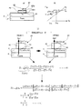
図22(A)〜図22(C)は、特許文献1(特開2006−308538号公報)の図5に記載される体温計の例を説明するための図である。図22(A)では、特許文献1の図7の内容を、そのまま記載している。図22(B)および図22(C)は、特許文献1の図7に記載される例の動作を説明するために、今回、新規に追加した補助的な図である。
22A to 22C are diagrams for explaining an example of the thermometer described in FIG. 5 of Patent Document 1 (Japanese Patent Laid-Open No. 2006-308538). In FIG. 22A, the contents of FIG. 7 of
図22(A)に示されるように、体温計本体3は、人体2上に設けられている。体温計本体3は、第1温度測定部3Aと第2温度測定部3Bを備えている。第1温度測定部3Aは、人体2の体表面2Aに接触する接触面300Aを有している断熱材37と、熱流束調整手段として、断熱材37と外気との間に設けられた第1の断熱材としての断熱材38Aとを備えている。また、温度測定部3Bは、温度測定部3Aの接触位置から距離Lだけ離れた位置における体表面2Aに接触する接触面300Bを有している断熱材37と、熱流束調整手段として、断熱材37と外気との間に第2の断熱材としての断熱材38Bを備えている。すなわち、断熱材37は、第1温度測定部3Aと第2温度測定部3Bとで共通しており、共通の熱抵抗値を有している。
As shown in FIG. 22A, the thermometer main body 3 is provided on the
第1温度測定部3Aは、体表面2Aの温度を第1の基準温度として測定する第1基準温度測定部としての体表面センサー31Aと、断熱材37と断熱材38Aとの界面301Aの温度を第1の参照温度として測定する第1参照温度測定部としての中間センサー32Aとを備えている。
The first
また、温度測定部3Bは、体表面2Aの温度を第2の基準温度として測定する第2基準温度測定部としての体表面センサー31Bと、断熱材37と断熱材38Bとの界面301Bの温度を第2の参照温度として測定する第2の参照温度測定部としての中間センサー32Bとを備えている。断熱材38の材料は、断熱材37の材料とは異なっている。したがって、第1温度測定部3Aと第2温度測定部3Bとの間の熱抵抗値を異なり、各温度測定部には、異なる熱流束が生じることになる。
Further, the
図22(B)では、図22(A)に示される体温計本体の構造を簡略化して示している。図22(C)では、図22(B)に示される第1温度測定部3Aおよび2温度測定部3Bにおける、熱抵抗と熱流束とが記載されている。
In FIG. 22 (B), the structure of the thermometer main body shown in FIG. 22 (A) is simplified and shown. In FIG. 22C, the thermal resistance and heat flux in the first
図22(C)に示されるように、人体2の表層部の熱抵抗はRsであり、また、各温度測定部3A,3Bと人体2との接触箇所には、接触抵抗Rtが存在する。(Rs+Rt)の値は不明である。また、共通の断熱材37の熱抵抗はRu0(既知)である。また、第1温度測定部3Aの大気側に設けられる断熱材38Aの熱抵抗は(Ru1+RV)である。なお、RVは大気に近い表層部の熱抵抗である。また、第2温度測定部3Bの大気側に設けられる断熱材38Bの熱抵抗は(Ru2+RV)である。
As shown in FIG. 22 (C), the thermal resistance of the surface layer portion of the
また、図22(C)では、体表面センサー31A,31Bによって測定された温度をTb1,Tb3とし、中間センサー32A,32Bによって測定された温度をTb2,Tb4とする。
In FIG. 22C, the temperatures measured by the
図22(C)の左側に太線の矢印で示されるように、第1温度測定部3Aには、人体2の深部から、断熱材37と断熱材38Aとが接触する界面301Aに向かう熱流束が生じる。この熱流束は、人体2の深部(温度Tcore)から体表面2Aに向かう熱流束Q(s+t)と、体表面2Aから界面301Aに向かう熱流束Qu1と、に分けることができる。また、第2温度測定部3Bにおいても、人体2の深部から、断熱材37と断熱材38Aとが接触する界面301Aに向かう熱流束が生じ、この熱流束は、人体2の深部(温度Tcore)から体表面2Aに向かう熱流束Q(s+t)と、体表面2Aから界面301Aに向かう熱流束Qu2と、に分けることができる。
As shown by a thick arrow on the left side of FIG. 22C, the first
熱流束は、2点の温度の差を、2点間の熱抵抗値で除算して求めることができる。よって、熱流束Q(s+t)は、下記の式(A)で示され、熱流束Qu1は、下記の式(B)で示され、熱流束Qu2は、下記の式(C)で示される。
Q(s+t)=(Tcore−Tb1)/(Rs+Rt)・・・(A)
Qu1=(Tb1−Tb2)/Ru0・・・(B)
Qu2=(Tb3−Tb4)/Ru0・・・(C)
ここで、人体2における熱流束と、温度測定部3A,3Bにおける熱流束とは等しい。よって、Q(s+t)=Qu1が成立し、同様に、Q(s+t)=Qu2が成立する。
したがって、式(A)ならびに式(B)から、下記(D)式が得られ、式(A)と式(C)から、下記の式(E)が得られる。
Tcore={(Rs+Rt)/Ru0}・(Tb1―Tb2)+Tb1・・・(D)
Tcore={(Rs+Rt)/Ru0}・(Tb3―Tb4)+Tb3・・・(E)
図23は、熱流束が定常状態であるときの体温計の接触部モデルと、深部温度の算出式を示す図である。この図23の上側に示される図は、特許文献1の図4の内容を、ほぼそのまま記載した図である。図23の上側の図に示されるように、2つの異なる熱流束(Q(s+t)とQu1、Q(s+t)とQu2)は、各々、傾きが異なる直線で示される。各熱流束において、人体2における熱流束と、温度測定部3A,3Bにおける熱流束とは等しいという条件より、上述のとおり、深部温度Tcoreの算出式である(D)式と(E)式とが得られる。
The heat flux can be obtained by dividing the temperature difference between two points by the thermal resistance value between the two points. Therefore, the heat flux Q (s + t) is represented by the following formula (A), the heat flux Qu1 is represented by the following formula (B), and the heat flux Qu2 is represented by the following formula (C).
Q (s + t) = (Tcore−Tb1) / (Rs + Rt) (A)
Qu1 = (Tb1-Tb2) / Ru0 (B)
Qu2 = (Tb3-Tb4) / Ru0 (C)
Here, the heat flux in the
Therefore, the following formula (D) is obtained from the formula (A) and the formula (B), and the following formula (E) is obtained from the formula (A) and the formula (C).
Tcore = {(Rs + Rt) / Ru0}. (Tb1-Tb2) + Tb1 (D)
Tcore = {(Rs + Rt) / Ru0}. (Tb3-Tb4) + Tb3 (E)
FIG. 23 is a diagram showing a contact part model of the thermometer when the heat flux is in a steady state and a calculation formula for the deep part temperature. The figure shown on the upper side of FIG. 23 is a diagram in which the contents of FIG. As shown in the upper diagram of FIG. 23, two different heat fluxes (Q (s + t) and Qu1, Q (s + t) and Qu2) are indicated by straight lines having different inclinations. In each heat flux, as described above, the equations (D) and (E), which are the calculation formulas for the deep temperature Tcore, under the condition that the heat flux in the
式(D)と式(E)に基づいて、{(Rs+Rt)/Ru0}の項を除去することができる。この結果、深部温度Tcoreの算出式である、下記の式(F)が得られる。
![]()
![]()
図24は、図22に示した従来例において、熱収支による測定誤差が生じる様子を示している。なお、図24では、説明の便宜上、各体表面センサー31A〜32Bの測定温度を、T1〜T4と表記している。
FIG. 24 shows how measurement errors occur due to the heat balance in the conventional example shown in FIG. In FIG. 24, for convenience of explanation, the measured temperatures of the
図24において、人体2と環境(ここでは大気)7との間、あるいは、温度測定部3A,3Bと環境7との間に生じる熱収支(熱の授受)が、太線の破線の矢印で示されている。上述のとおり、人体2の深部から温度測定部3A,3Bに向かう熱流束が生じるが、実際の温度測定に際して、熱流束の一部は、例えば、温度測定部3A,3Bから環境(大気)7に逃げ、また、例えば、環境(大気)7から温度測定部3A,3Bに熱が流入する。先に説明した、特許文献1に記載される技術では、熱収支が生じない、理想的な熱流束を前提としているため、この点で、わずかながら測定誤差が生じるのは否めない。
In FIG. 24, the heat balance (transfer of heat) generated between the
図24の下側に示される式(F)では、従来例における深部温度Tcoreを、真の深部温度Tcと、熱収支による誤差成分ΔTcとに分けて記載してある。つまり、特許文献1に記載される測定方法では、測定された深部温度Tcoreには、熱収支に伴う測定誤差が、わずかながら存在することになる。この熱収支に伴う誤差成分を、例えば、補正演算等によって除去することができれば、深部温度の測定精度を、さらに向上させることができる。
In the formula (F) shown on the lower side of FIG. 24, the deep temperature Tcore in the conventional example is described by being divided into a true deep temperature Tc and an error component ΔTc due to heat balance. In other words, in the measurement method described in
次に、本発明の実施形態について図面を参照して説明する。 Next, embodiments of the present invention will be described with reference to the drawings.
(第1の実施形態)
図1(A)〜図1(C)は、第1の実施形態における、深部温度の測定方法を説明するための図である。図1では、本実施形態における温度測定装置の要部(温度測定部)のみが記載されている。なお、温度測定装置の全体の構成例については、図8を用いて後述する。
(First embodiment)
FIG. 1A to FIG. 1C are diagrams for explaining a method for measuring a deep temperature in the first embodiment. In FIG. 1, only the principal part (temperature measurement part) of the temperature measurement apparatus in this embodiment is described. An example of the overall configuration of the temperature measuring device will be described later with reference to FIG.
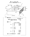
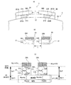
まず、図1(A)を参照する。本実施形態における温度測定装置は、基材40と、基材40の第1測定点p1における温度を、第1温度Tbとして測定する第1温度センサー50と、基材40の、第1測定点p1とは異なる第2測定点p2における温度を第2温度Tpとして測定する第2温度センサー52と、基材40の周囲の環境(ここでは大気)7の温度を第3温度として取得する環境温度取得部53と、を有する。
First, reference is made to FIG. The temperature measuring device in the present embodiment includes a
基材40は、被測定体6に接触する接触面である第1面SR1と、第1面SR1に対向する面であって、環境側の面(つまり、基材40の上面)である第2面SR2と、を有する。基材40の第1面SR1は、被測定体6の表層部5の表面に接触した状態となっている。
The
基材40の第2面SR2は、例えば、第1面SR1に対して平行な面である。また、基材40は、熱を伝達する熱媒体である。基材40としては、例えば、所定の熱伝導率(あるいは熱抵抗)をもつ材料(例えばシリコンゴム)を使用することができる。基材40の材料としては、例えば、シリコンゴムを使用することができる。被測定体6は、人体であってもよく、また、炉や配管等の無機的な構造物であってもよい。
The second surface SR2 of the
また、第1温度センサー50、第2温度センサー52ならびに第3温度センサー54としては、例えば、温度値を抵抗値に変換するタイプの温度センサーを使用することができ、また、温度値を電圧値に変換するタイプの温度センサー等を使用することができる。なお、温度値を抵抗値に変換するタイプの温度センサーとしては、チップサーミスターや、サーミスターパターンがプリントされたフレキシブル基板、白金測温抵抗体等を採用することができる。また、温度値を電圧値に変換するタイプの温度センサーとしては、熱電対素子や、PN接合素子、ダイオード等を採用することができる。
As the
被測定体6の深部4の深部温度はTcであり、この深部温度Tcが測定対象となる温度である。図1(A)の例では、破線の矢印で示されるように、被測定体6の深部4から環境7に向かう熱流(熱流束)Qaが生じている。
The deep part temperature of the
環境7は、例えば、大気等の熱媒体であり、周囲媒体あるいは環境媒体と言い換えることができる。基材40の周囲の媒体に、大気の構成成分ではないガス成分が含まれるような場合であっても、その媒体は環境(周囲媒体、環境媒体)7ということができる。また、その媒体は、気体に限定されるものではない。
The
また、第1測定点p1および第2測定点p2は、基材40の外表面上、または基材40の内部に設けることができる。つまり、第1測定点p1および第2測定点p2は、基材40の外表面上、または基材40の内部に位置する任意の2点である。
The first measurement point p1 and the second measurement point p2 can be provided on the outer surface of the
また、第1温度センサー50および第2温度センサー52は、第3温度Toutの値が異なるという条件の下で、第1温度Tpおよび第2温度Tbを複数回(ここでは3回とする)、測定する。
Further, the
第1測定点p1の温度Tp(すなわち第1温度)ならびに第2測定点p2の温度Tb(すなわち第2温度)は、共に、熱源としての深部温度Tcの影響を受けて変動し、かつ、熱流の終端である環境7の温度Tout(すなわち第3温度)の影響を受けて変動する。
The temperature Tp (that is, the first temperature) at the first measurement point p1 and the temperature Tb (that is, the second temperature) at the second measurement point p2 both vary under the influence of the deep temperature Tc as the heat source, and the heat flow Fluctuates under the influence of the temperature Tout (that is, the third temperature) of the
例えば、第1温度Tp=TPAとしたとき、第2温度Tb=aTPA+bと表すことができる。aは一次関数の傾き(第1の傾き)であり、bは、切片(第1の切片)である。また、第1の切片bは、環境温度(第3温度)Toutによって線形に変化する。すなわち、b=cTout+dと表すことができる。cは一次関数の傾き(第2の傾き)であり、dは、切片(第2の切片)である。 For example, when the first temperature Tp = T PA, can be expressed as the second temperature Tb = aT PA + b. a is the slope of the linear function (first slope), and b is the intercept (first intercept). In addition, the first intercept b changes linearly with the environmental temperature (third temperature) Tout. That is, it can be expressed as b = cTout + d. c is the slope of the linear function (second slope), and d is the intercept (second intercept).
温度測定部に含まれる演算部(図1では不図示,図2〜図4における参照符号74)は、本実施形態においては、3回の測定によって得られた第1温度(Tb1〜Tb3)および第2温度(Tp1〜Tp3)、ならびに3回の測定に対応する異なる値の第3温度(Tout1〜Tout3)に基づいて、第1面SR1から離れた、被測定体6の深部4における深部温度Tcを、深部温度の演算式である第1算出式(式(1))による演算によって求める。つまり、Tc=d/(1−a−c)となる。
In the present embodiment, the calculation unit included in the temperature measurement unit (not shown in FIG. 1,
第1算出式(式(1))は、深部温度(Tc)と環境温度(Tout)とが等しいときは、熱収支はゼロとなるという点に着目して導出される(詳しい導出過程については後述する)。3回の測定によって得られた温度データから、定数a,c,dを決定し、式(1)に代入することによって、深部温度Tcが求まる。これが本実施形態における深部温度Tcの算出方法である。 The first calculation formula (formula (1)) is derived by paying attention to the fact that the heat balance is zero when the deep temperature (Tc) and the environmental temperature (Tout) are equal (for the detailed derivation process) Will be described later). Determining constants a, c, and d from the temperature data obtained by three measurements and substituting them into equation (1), the deep temperature Tc is obtained. This is the method for calculating the deep temperature Tc in this embodiment.
従来例では、環境温度が一定であるという条件の下で、2つの温度測定部における断熱材の種類を異ならせて、2つの異なる熱流束を生成していたが、本態様では、環境温度が異なる、少なくとも2つの系において熱流束を生成する。なお、以下の説明で環境という用語を使用するが、環境は、例えば大気等の熱媒体であり、周囲媒体あるいは環境媒体と言い換えることができる。 In the conventional example, under the condition that the environmental temperature is constant, two different heat fluxes are generated by different types of heat insulating materials in the two temperature measurement units. However, in this aspect, the environmental temperature is Generate heat flux in at least two different systems. In addition, although the term environment is used in the following description, the environment is, for example, a heat medium such as the atmosphere, and can be restated as an ambient medium or an environmental medium.
従来例における熱流のモデルでは、2つの温度測定系における環境温度Toutは同じ値(つまり一定)となっている。よって、各系における深部温度Tcと環境温度Tout間に生じる熱流が一定であり、従来例は、このことを前提条件としている。被測定体から環境に向かう、例えば鉛直方向の熱流が一定であるということは、その鉛直方向の熱流の一部が、例えば基材の側面を経由して環境に逃げるといった熱収支が生じないことを前提として成立する。 In the heat flow model in the conventional example, the environmental temperature Tout in the two temperature measurement systems has the same value (that is, constant). Therefore, the heat flow generated between the deep temperature Tc and the environmental temperature Tout in each system is constant, and the conventional example assumes this. The fact that the vertical heat flow from the measured object to the environment, for example, is constant means that there is no heat balance that a part of the vertical heat flow escapes to the environment, for example, via the side of the substrate. It is established on the assumption.
しかし、温度測定装置の小型化が促進され、基材のサイズが小さくなると、被測定体と環境との間の熱収支(例えば、基材の側面からの熱の逃げ等)が顕在化する。この場合、深部温度Tcと環境温度Tout間に生じる熱流が一定であるという前提が満足されなくなる。 However, when the downsizing of the temperature measuring device is promoted and the size of the base material is reduced, a heat balance (for example, heat escape from the side surface of the base material) between the measurement object and the environment becomes obvious. In this case, the assumption that the heat flow generated between the deep temperature Tc and the environmental temperature Tout is constant is not satisfied.
これに対して、本実施形態では、複数の熱流の系において、各熱流の一端は、温度変動が許容されている環境であり、例えば、第1の系では、環境温度はTout1(任意の温度)であり、第2の系では環境温度はTout2(Tout1とは異なる任意の温度)である。よって、複数の熱流の系の間で、環境温度(Tout)と深部温度(Tc)との間で生じる熱流が一定でなければならない、という、従来例のような制約が生じない。つまり、各系の熱流束には、熱収支による熱の移動が本来的に含まれており、環境温度Tout(任意の温度)と被測定体の深部温度Tcとの間で、その熱収支の成分も含むような熱流が生じるだけである。 In contrast, in the present embodiment, one end of each heat flow in a plurality of heat flow systems is an environment in which temperature fluctuation is allowed. For example, in the first system, the environmental temperature is Tout1 (arbitrary temperature). In the second system, the environmental temperature is Tout2 (any temperature different from Tout1). Therefore, there is no restriction as in the conventional example that the heat flow generated between the environmental temperature (Tout) and the deep temperature (Tc) must be constant among a plurality of heat flow systems. That is, the heat flux of each system inherently includes heat transfer due to the heat balance, and the heat balance between the environmental temperature Tout (arbitrary temperature) and the deep temperature Tc of the measured object. Only a heat flow is generated that also contains the components.
そして、このような熱流の系では、基材における任意の2点(第1測定点と第2測定点)の温度は、環境温度(Tout)を変数(パラメーター)として含む式によって表すことができる。 In such a heat flow system, the temperature at any two points (first measurement point and second measurement point) on the substrate can be expressed by an equation including the environmental temperature (Tout) as a variable (parameter). .
また、深部温度Tcと環境温度Toutとが等しいときは、熱収支はゼロとなる。よって、例えば、深部温度Tcの演算を行う際に、深部温度Tcと環境温度Toutとが等しいという条件を与えることによって、熱収支による測定誤差をゼロとすることができ、上述した第1算出式(式(1))が得られる。 Further, when the deep temperature Tc and the environmental temperature Tout are equal, the heat balance is zero. Therefore, for example, when the deep part temperature Tc is calculated, by giving the condition that the deep part temperature Tc and the environmental temperature Tout are equal, the measurement error due to the heat balance can be made zero, and the above-described first calculation formula (Formula (1)) is obtained.
また、第1測定点p1(第1温度センサー50が設けられる位置)、ならびに、第2測定点p2(第2温度センサー52が設けられる位置)に関しては、種々のバリエーションが考えられる。ここで、図1(B)を参照する。
Various variations can be considered for the first measurement point p1 (position where the
第1測定点p1および第2測定点p2は、基材40の表面上や側面上、すなわち基材40の外表面上に位置することができ、また、基材40の内部に位置することもできる。また、いずれか一方が、基材40の表面上や側面上に位置し、いずれか他方が、基材40の内部に位置することもできる。なお、第1測定点p1と第2測定点p2を種々、変化させて、深部温度を測定した結果については、図11〜図16を用いて後述する。
The first measurement point p <b> 1 and the second measurement point p <b> 2 can be located on the surface or side surface of the
本実施形態では、第1測定点p1は、被測定体6側の測定点とし、第2測定点p2は、環境(大気)7側の測定点とする。
In the present embodiment, the first measurement point p1 is a measurement point on the measured
図1(B)に示すように、基材40の接触面SR1に垂直な垂線の方向における、第1面(接触面)SR1からの距離を考え、第1測定点p1の距離をLAとし、第2測定点p2の距離をLBとする。基材40の高さ(第1面SR1から第2面SR2までの距離)をLCとする。
As shown in FIG. 1B, considering the distance from the first surface (contact surface) SR1 in the direction perpendicular to the contact surface SR1 of the
距離LAおよび距離LBについては、0≦LA,LB≦LCが成立し、かつ、LA≦LBが成立する。つまり、第1測定点p1および第2測定点p2の、基材40の第1面SR1からの距離LA,LBは、0以上であり、基材40の高さ(頂部における高さ)はLC以内である。また、第1測定点p1の、基材40の第1面SR1からの距離LAと、第2測定点p2の、基材40の第1面からの距離LBとを比較した場合、LA<LBであってもよく、また、LA=LBであってもよい。
For the distance LA and the distance LB, 0 ≦ LA and LB ≦ LC are satisfied, and LA ≦ LB is satisfied. That is, the distances LA and LB of the first measurement point p1 and the second measurement point p2 from the first surface SR1 of the
また、LA<LBのときは、第1測定点p1の方が、第2測定点p2よりも被測定体6の近くに位置している。LA=LBのときは、第1測定点p1と第2測定点p2とは、横一線の位置にあり、距離に関しては優劣がない。但し、第1測定点p1と第2測定点p2とは、空間において同じ位置ではなく、必ず異なる位置にある。なお、LA=LBの場合でも、深部温度Tcを正確に測定可能である点に関しては、図14を用いて後述する。
When LA <LB, the first measurement point p1 is located closer to the measured
次に、図1(C)を参照する。図1(C)の例では、点x1と点x2は、横一線の位置にある。しかし、点x1から、基材40の側面までの最小距離はL1であり、一方、点x2から、基材40の側面までの最小距離はL2であり、L1<L2である。点x1の方が、環境(大気)との熱交換が容易である。よって、例えば、点x1を、環境側の測定点である第2測定点p2とし、点x2を、被測定体側の測定点である第1測定点p1とすることができる。
Next, reference is made to FIG. In the example of FIG. 1C, the point x1 and the point x2 are in a horizontal line position. However, the minimum distance from the point x1 to the side surface of the
次に、図2〜図4を用いて、「第3温度(環境温度Tout)の値が異なるという条件の下で、第1温度Tbおよび第2温度Tpを複数回、測定する」ことを担保するための測定方法の例について説明する。 Next, using FIG. 2 to FIG. 4, it is guaranteed that “the first temperature Tb and the second temperature Tp are measured a plurality of times under the condition that the value of the third temperature (environment temperature Tout) is different”. An example of a measurement method for doing this will be described.
図2(A)および図2(B)は、温度測定方法の一例、ならびに、その温度測定方法を実施するための温度測定装置の構成の一例を示す図である。 2A and 2B are diagrams illustrating an example of a temperature measurement method and an example of a configuration of a temperature measurement device for performing the temperature measurement method.
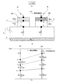
図2(A)に示される温度測定装置は、温度測定部43と、環境温度取得部53と、演算部74と、温度測定部43および演算部74の動作を制御する制御部73と、を含む。
図2(A)の例では、環境温度取得部53は、無線通信部CBを有している。よって、外部の空調器57から、無線通信によって環境温度(第3温度)の情報を取得することができる。また、環境温度取得部53は、環境温度センサー(第3温度センサー)54によって、自ら環境温度(第3温度)を測定することができる。
2A includes a
In the example of FIG. 2A, the environmental
なお、空調器57は、大気温度センサー55と、無線通信部CAと、を有している。また、制御部73は、演算部74と、測定タイミング制御部75と、を有している。測定タイミング制御部75は、タイミング制御信号ST1を出力し、このタイミング制御信号ST1によって、第1温度センサー50および第2温度センサー52による、第1温度Tbならびに第2温度Tpの測定タイミングと、環境温度取得部53による、第3温度Toutの取得タイミングとを制御する。
The
図2(B)に示されるように、第1温度および第2温度の測定ならびに環境温度の情報の取得のために、第1測定期間(第1時間帯)〜第3測定期間(第3時間帯)が設けられる。制御部73は、各測定期間毎に、複数回の温度測定あるいは温度情報の取得を実行し、得られたデータに基づいて、第1算出式(式(1))による演算を実行して、深部温度Tcを求める。
As shown in FIG. 2B, in order to measure the first temperature and the second temperature and to acquire information on the environmental temperature, the first measurement period (first time zone) to the third measurement period (third time). Obi) is provided. The
「第3温度(環境温度Tout)の値を異ならせる」ための方法としては、空調器等を利用する積極方法と、時間軸上での環境温度のゆらぎ(微小な変動)に着目して、測定タイミングを調整するという消極的な方法とがあるが、図2の例では、後者の消極的な方法が採用されている。 As a method for “changing the value of the third temperature (environment temperature Tout)”, paying attention to an active method using an air conditioner and the like, and fluctuation (small fluctuation) of the environment temperature on the time axis, There is a passive method of adjusting the measurement timing, but in the example of FIG. 2, the latter passive method is adopted.
例えば、基材40の第1測定点p1における第1温度Tb、ならびに基材40の第2測定点p2における第2温度Tpを3回測定するとき、各測定間の時間間隔があまりに短いと、「異なる環境温度(第3温度)の下で3回測定する」という条件を満たすことができない場合がある。よって、本例では、第1回目の測定用の第1時間帯(つまり第1測定期間)と、第2回目の測定用の第2時間帯(つまり、第2測定期間)と、第3回目の測定用の第3時間帯(つまり、第3測定期間)とを設ける。
For example, when measuring the first temperature Tb at the first measurement point p1 of the
各時間帯(測定期間)は、例えば1分(3つの時間帯の合計が3分)とすることができる。第1時間帯(第1測定期間)は、時刻t1〜時刻t4の期間であり、例えば、20毎に温度測定が実行される。つまり、時刻t1,時刻t2,時刻t3において、3回の温度測定が実行され、図示されるような9個のデータが得られる。そして、これらのデータの平均演算(単純な加算平均でもよく、重み付け平均でもよい)によって、第1回目の温度測定値(Tb1,Tp1,Tout1)が決定される。 Each time zone (measurement period) can be, for example, 1 minute (a total of 3 time zones is 3 minutes). The first time period (first measurement period) is a period from time t1 to time t4. For example, temperature measurement is performed every 20th. That is, at time t1, time t2, and time t3, three temperature measurements are executed, and nine pieces of data as illustrated are obtained. Then, the first temperature measurement values (Tb1, Tp1, Tout1) are determined by averaging these data (a simple addition average or a weighted average).
また、第2時間帯(第2測定期間)は、時刻t4〜時刻t7の時間帯である。第2時間帯においても、3回の温度測定が実行され、各測定結果の平均演算(単純な加算平均でもよく、重み付け平均でもよい)によって、第2回目の温度測定値(Tb2,Tp2,Tout2)が決定される。 The second time zone (second measurement period) is the time zone from time t4 to time t7. Also in the second time zone, three temperature measurements are performed, and the second temperature measurement value (Tb2, Tp2, Tout2) is calculated by averaging each measurement result (a simple addition average or a weighted average may be used). ) Is determined.
第3時間帯(第3測定期間)は、時刻t7〜t10の時間帯である。第3時間帯においても、3回の温度測定が実行され、各測定結果の平均演算(単純な加算平均でもよく、重み付け平均でもよい)によって、第2回目の温度測定値(Tb3,Tp3,Tout3)が決定される。以上の処理を、第1ステップST1の処理とする。平均演算という用語は、最も広義に解釈するものとする。 The third time zone (third measurement period) is a time zone from time t7 to t10. Also in the third time zone, three temperature measurements are performed, and the second temperature measurement values (Tb3, Tp3, Tout3) are calculated by averaging the measurement results (which may be a simple addition average or a weighted average). ) Is determined. The above process is the process of the first step ST1. The term average operation is to be interpreted in the broadest sense.
次に、ステップS2において、得られたデータに基づいて、先に図1(A)に示した、定数a,c,dを算出する。次に、ステップS3において、第1算出式(式(1))に基づいて、深部温度Tcを測定する。 Next, in step S2, constants a, c, and d shown in FIG. 1A are calculated based on the obtained data. Next, in step S3, the deep temperature Tc is measured based on the first calculation formula (formula (1)).
図2に示される例では、空調器等を用いて積極的に環境の温度を変化させることなく、第1温度および第2温度(ならびに第3温度)に関して、異なる環境温度下で測定された複数の温度データを、比較的容易に得ることができる。 In the example shown in FIG. 2, a plurality of temperatures measured at different environmental temperatures with respect to the first temperature and the second temperature (and the third temperature) without actively changing the temperature of the environment using an air conditioner or the like. The temperature data can be obtained relatively easily.
図3(A)および図3(B)は、温度測定方法の他の例、ならびに、その温度測定方法を実施するための温度測定装置の構成の他の例を示す図である。図3(A)に示される温度測定装置には、複数回の温度測定を実行するタイミングを決めるための、タイミング制御情報を入力するタイミング制御情報入力部83が設けられている。制御部73は、タイミング制御情報入力部83から、タイミング制御情報(ここでは、測定指示トリガーTGとする)が入力される毎に、例えば、第1温度センサー50、第2温度センサー52ならびに第3温度センサー54に、温度測定を実行させる。
FIGS. 3A and 3B are diagrams showing another example of the temperature measuring method and another example of the configuration of the temperature measuring device for carrying out the temperature measuring method. The temperature measuring device shown in FIG. 3A is provided with a timing control
図3の例では、「第3温度(環境温度Tout)の値を異なるという条件の下で、第1温度Tbおよび第2温度Tpを複数回、測定する」ことは、ユーザー自身の行為によって担保される。 In the example of FIG. 3, “measuring the first temperature Tb and the second temperature Tp multiple times under the condition that the value of the third temperature (environment temperature Tout) is different” is secured by the user's own action. Is done.
例えば、ユーザーは、第1回目の測定を行うとき、温度測定装置の外に設けられる外部の空調器57の温度を第1の温度に設定し、設定から所定の時間が経過すると、タイミング制御情報入力部を経由して、タイミング制御情報としての測定指示トリガーTG)を入力する。上述したように、制御部73は、タイミング制御情報入力部83からタイミング制御情報が入力される毎に、例えば、第1温度センサー50、第2温度センサー52ならびに第3温度センサー54に温度測定を実行させる。測定タイミングは、測定タイミング制御部75によって制御される。
For example, when the user performs the first measurement, the temperature of the
温度測定は、例えば、タイミング制御情報(測定指示トリガーTG)の入力毎に1回行うことができ、また、タイミング制御情報の入力毎に複数回の温度測定を実行して、得られた測定値を平均する等して、測定値を求めてもよい。以降、ユーザーは、空調器57の温度を第2の温度に設定した後、タイミング制御情報を入力し、次に、空調器57の温度を第3の温度に設定した後、タイミング制御情報を入力する。例えば、ユーザーは、3回のタイミング制御情報を入力する。
The temperature measurement can be performed, for example, once for each input of timing control information (measurement instruction trigger TG), and a measured value obtained by performing a plurality of temperature measurements for each input of timing control information. You may obtain | require a measured value by averaging. Thereafter, the user inputs the timing control information after setting the temperature of the
3回分の温度情報が取得されると、演算部74は、取得された温度情報に基づく、深部温度Tcを求めるための演算(算出式に基づく演算)を自動的に実行し、この結果、深部温度Tcが求められる。求められた深部温度Tcは、例えば、ユーザーに報知(表示、音声による通知等を含む)される。図3の例では、ユーザー自身が、各測定毎の環境温度を異ならせることから、温度測定装置自体が、環境温度を管理する負担が生じない。
When the temperature information for three times is acquired, the
測定手順は、図3(B)のステップS4〜ステップS6のとおりである。なお、以上の例は一例である。 The measurement procedure is as shown in steps S4 to S6 in FIG. The above example is an example.
図4(A)および図4(B)は、温度測定方法の他の例、ならびに、その温度測定方法を実施するための温度測定装置の構成の他の例を示す図である。図4の例では、温度測定部が、環境の温度(第3温度)を変化させることができる環境温度調整部CDを有している。制御部73は、そして、1回の温度測定が終了する毎に、環境温度調整部CDによって環境の温度(第3温度)を変化させる。
FIGS. 4A and 4B are diagrams showing another example of the temperature measuring method and another example of the configuration of the temperature measuring device for carrying out the temperature measuring method. In the example of FIG. 4, the temperature measurement unit includes an environmental temperature adjustment unit CD that can change the environmental temperature (third temperature). The
環境温度調整部CDは、環境温度(第3温度Tout)を変化させる機能をもつ。図4(A)の例では、環境温度調整部CDとして、例えば、温度測定装置の外に設けられる外部の空調器57の設定温度を、遠隔制御によって調整する機能をもつ調整器CC1を使用することができる。調整器CC1の動作は、測定タイミング制御部75からの制御信号ST2によって制御される。
The environmental temperature adjusting unit CD has a function of changing the environmental temperature (third temperature Tout). In the example of FIG. 4A, as the environmental temperature adjustment unit CD, for example, the adjuster CC1 having a function of adjusting the set temperature of the
また、図4(B)の例では、環境温度調整部CDとして、例えば、温度測定装置の内部に設けられた、気流生成部(例えば、気流の温度を変化させる機能を有する)CC2を使用する。気流生成部CC2は、ファン(扇風機)や、気流を噴射する微小ノズル等によって構成することができる。気流生成部CC2の動作は、測定タイミング制御部75からの制御信号ST3によって制御される。
In the example of FIG. 4B, for example, an air flow generation unit (for example, having a function of changing the temperature of the air flow) CC2 provided inside the temperature measurement device is used as the environmental temperature adjustment unit CD. . The airflow generation unit CC2 can be configured by a fan (electric fan), a minute nozzle that ejects an airflow, or the like. The operation of the airflow generation unit CC2 is controlled by a control signal ST3 from the measurement
環境温度調整部CDを利用することによって、測定毎に、環境温度Toutを確実に異ならせることができる。また、環境温度Toutを正確な温度に設定することができる。また、例えば、第1測定時の環境温度Tout1と第2測定時の環境温度Tout2との差を、大きく設定することもできる。なお、以上の例は一例である。 By using the environmental temperature adjusting unit CD, the environmental temperature Tout can be reliably varied for each measurement. Further, the environmental temperature Tout can be set to an accurate temperature. Further, for example, the difference between the environmental temperature Tout1 during the first measurement and the environmental temperature Tout2 during the second measurement can be set large. The above example is an example.
次に、第1算出式(図1(A)の式(1)を用いた深部温度Tcの演算)について、図5〜図7を用いて、具体的に説明する。 Next, the first calculation formula (calculation of the deep temperature Tc using the formula (1) in FIG. 1A) will be specifically described with reference to FIGS.
図5(A)〜図5(C)は、環境温度が一定であるという条件下における、第1温度と第2温度との間の関係、ならびに、その関係を深部温度の算出式に適用した場合の結果を示す図である。 5 (A) to 5 (C), the relationship between the first temperature and the second temperature under the condition that the environmental temperature is constant, and the relationship applied to the calculation formula for the deep temperature. It is a figure which shows the result of a case.
図5(A)において、基材40、第1温度センサー50および第2温度センサー52は、温度測定部43を構成する。基材40は、第1面(接触面)SR1と第2面(基材40の上面)SR2とを有している。この温度測定部43は、被測定体6(例えば人体)6に、例えば、貼り付けられている。第1温度センサー50によって測定される第1温度はTbと表記されている。また、第2温度センサー52によって測定される第2温度はTpと表記されている。
In FIG. 5A, the
図5(B)は、第2温度Tpと第1温度Tbとの関係を示す図である。図5(B)において、横軸はTpであり、縦軸は、第2温度Tpおよび第1温度Tbの温度Tである。環境温度(第3温度Tout)が一定である状態で、第1温度Tpが線形に変化すると、第2温度Tbも線形に変化する。つまり、第1温度Tbは、第2温度Tpに対して線形性を有する。 FIG. 5B is a diagram showing the relationship between the second temperature Tp and the first temperature Tb. In FIG. 5B, the horizontal axis is Tp, and the vertical axis is the temperature T of the second temperature Tp and the first temperature Tb. When the first temperature Tp changes linearly in a state where the environmental temperature (third temperature Tout) is constant, the second temperature Tb also changes linearly. That is, the first temperature Tb has linearity with respect to the second temperature Tp.
図5(B)に示されるように、第1温度Tbは、第2温度Tpを変数とする1次関数によって表される。つまり、下記の式(2)が成立する。
図5(C)は、2回の温度測定によって得られた温度データT1〜T4を、先に説明した深部温度の算出式に適用した場合の結果を示す図である。時刻t1における温度測定によって、第1温度T1と第2温度T2が得られたとする。また、時刻t2における温度測定によって、第1温度T3と第2温度T4が得られたとする。T1〜T4は、下記式(3)によって表される。
![]()
![]()
図6(A)に示すように、変動する環境温度(第3温度)Toutは、環境温度取得部53に含まれる第3温度センサー54によって測定される。先に説明したように、第2温度TpをTPAとしたとき、Tb=aTPA+bと表すことができる。定数bは、第1切片(第1オフセット値)であり、この第1切片bは、環境温度(第3温度)Toutに対する線形性を有する。
As shown in FIG. 6A, the fluctuating environmental temperature (third temperature) Tout is measured by a
つまり、図6(B)に示すように、Toutが変動すると、第1切片bの値は、環境温度(第3温度)Toutにしたがって、線形に変化する。したがって、下記の式(6)の関係が成立する。
![]()
![]()
図6(C)は、Tout1における、第2温度Tpと第1温度Tb(=Tb1)との関係、ならびに、Tout2における、第2温度Tpと第1温度Tb(=Tb2)との関係を示している。Toutが、Tout1からTout2に変化したとき、1次関数の傾き(第1の傾きa)には変化がないが、第1の切片bの値が、b1からb2に変化することから、TpとTbとの関係を示す1次関数は、b1とb2の差分の分だけ、平行にシフトされる。 FIG. 6C shows the relationship between the second temperature Tp and the first temperature Tb (= Tb1) at Tout1, and the relationship between the second temperature Tp and the first temperature Tb (= Tb2) at Tout2. ing. When Tout changes from Tout1 to Tout2, the slope of the linear function (first slope a) does not change, but since the value of the first intercept b changes from b1 to b2, Tp and The linear function indicating the relationship with Tb is shifted in parallel by the difference between b1 and b2.
このように、第1温度Tbは第2温度Tpだけでなく、環境温度(第3温度)Toutに対しても線形の関係を示す。上記式(6)を、上記式(3)に示されるTb=aTp+bという式に代入すると、下記の式(7)が得られる。
![]()
![]()
また、上記の式(6)を、式(5)に代入すると、式(8)が得られる。
![]()
![]()
ここで、第1回目の測定時に、第1温度としてのTb1、第2温度としてのTp1、第3温度としてのTout1が得られ、第2回目の測定時に、第1温度としてのTb2、第2温度としてのTp2、第3温度としてのTout2が得られ、第3回目の測定時に、第1温度としてのTb3、第2温度としてのTp3、第3温度としてのTout3が得られたとする。 Here, during the first measurement, Tb1 as the first temperature, Tp1 as the second temperature, and Tout1 as the third temperature are obtained. During the second measurement, Tb2 as the first temperature, second It is assumed that Tp2 as the temperature and Tout2 as the third temperature are obtained, and Tb3 as the first temperature, Tp3 as the second temperature, and Tout3 as the third temperature are obtained in the third measurement.
これらの9個の測定データは、式(9)の行列式によって表現することができる
図7(A)〜図7(D)は、第1実施形態における、深部温度の測定方法を示す図である。図7(A)に示すように、3点の温度、すなわち、第1温度Tb,第2温度Tp,第3温度Toutを、少なくとも3回測定する。得られた9個の測定データ(Tb1,Tp1、Tout1、Tb2,Tp2,Tout2、Tb3,Tp3,Tout3)は、図7(B)に示される行列式(9)によって、関係付けることができる。よって、複数の定数a,c,dは、図7(C)に示される、行列式(10)によって求めることができる。そして、図7(D)に示される式(1)によって、深部温度Tcを算出することができる。 FIG. 7 (A) to FIG. 7 (D) are diagrams showing a method for measuring the deep temperature in the first embodiment. As shown in FIG. 7A, three temperatures, that is, the first temperature Tb, the second temperature Tp, and the third temperature Tout are measured at least three times. The obtained nine measurement data (Tb1, Tp1, Tout1, Tb2, Tp2, Tout2, Tb3, Tp3, Tout3) can be related by the determinant (9) shown in FIG. 7B. Therefore, the plurality of constants a, c, d can be obtained by the determinant (10) shown in FIG. And the deep part temperature Tc is computable by Formula (1) shown by FIG.7 (D).
次に、温度測定装置の全体構成について説明する。図8(A)〜図8(C)は、温度測定装置の全体構成の例を示す図である。 Next, the overall configuration of the temperature measuring device will be described. FIG. 8A to FIG. 8C are diagrams illustrating an example of the entire configuration of the temperature measuring device.
図8(A)の例では、第1温度センサー50および第2温度センサー52は、基材40の内部に埋め込まれている。また、断熱材20a上に、環境温度取得部53としての第3温度センサー54が設けられている。第1温度センサー50、第2温度センサー52、基材40、環境温度取得部53としての第3温度センサー54は、第1ユニット100を構成する。
In the example of FIG. 8A, the
また、断熱材20b上には、第2ユニット200が設けられる。第2ユニット200は、制御部73および演算部74を含む。なお、演算部74は、機能ブロックとして、定数算出部や深部温度算出部を含むことができる。また、第2ユニット200には、図示はしないが、演算結果を報知する報知部(例えば表示部)を設けることもできる。
The
また、図8(A)の温度測定装置は、基材40における第1面(接触面)SR1を、被測定体6の表面に貼付するための貼付構造10を有している。貼付構造10は、例えば、粘着テープにより構成することができる。粘着テープは、剥離紙8と、支持層(粘着層)9とを有することができる。
8A has a
貼付構造10によって、第1ユニット100を、被測定体6の表面に貼付することができる。したがって、温度測定装置の操作性ならびに携帯性が向上する。また、例えば、温度測定装置を、幼児や乳幼児などの体温の計測のために使用する場合、幼児等は、頻繁に体を動かすことから、温度測定装置と体表面との接触を、所定時間、良好に保持することが困難である。しかし、このような場合でも、貼付構造10を用いて、温度測定装置の全体を、被測定体6の表面に貼付可能であることから、幼児や乳幼児が体を動かしたとしても、体表面と温度測定装置との接触状況を良好に維持できる。よって、正確かつ安定した温度測定な可能である。
The
図8(B)の例では、環境温度取得部53は、大気温度センサー55から環境温度の情報を受け取る。大気温度センサー55としては、例えば、環境の温度を制御する空調器に設けられている温度センサーを使用することができる(図2〜図4を参照)。
In the example of FIG. 8B, the environmental
図8(C)の例では、第1ユニット100と、第2ユニット200とを分離した、別体の構成が採用されている。第1ユニット100は、第1無線通信部CAを含み、第2ユニット200は、第2無線通信部CBを含む。
In the example of FIG. 8C, a separate configuration in which the
第1温度(Tb)の情報と第2温度(Tp)の情報、または、第1温度(Tb)の情報、第2温度(Tp)の情報および第3温度(Tout)の情報は、第1無線通信部CAから第2無線通信部CBに送信される。第2ユニットに設けられている演算部74は、第2無線通信部CBによって受信された、第1温度(Tb)の情報と第2温度(Tp)の情報、または、第1温度(Tb)の情報、第2温度(Tp)の情報および第3温度(Tout)の情報に基づいて演算を実行して、被測定体6の深部温度Tcを求める。
Information on the first temperature (Tb) and information on the second temperature (Tp), or information on the first temperature (Tb), information on the second temperature (Tp), and information on the third temperature (Tout) It is transmitted from the wireless communication unit CA to the second wireless communication unit CB. The
図8(C)の構成によれば、第1ユニット100(例えば温度測定装置の本体)の構成部品の数を、最小限に抑制することができ、第1ユニット100の軽量化が実現される。したがって、例えば、被測定体6としての被検者の体表面に、第1ユニット100を長時間、接触させた場合であっても、被検者に大きな負担を与えることがない。よって、例えば、長時間にわたって、連続的に温度をモニタリングすることが可能となる。
According to the configuration of FIG. 8C, the number of components of the first unit 100 (for example, the main body of the temperature measuring device) can be minimized, and weight reduction of the
また、第1ユニット100と第2ユニット200との間で、無線通信による温度データの送受信を行うことができることから、第2ユニット200を、第1ユニット100からある程度、離して設置することが可能となる。また、無線通信を利用することから、通信用の配線が不要である。よって、第1ユニットの取扱い性が向上する。また、第1ユニット100を、第2ユニット200から完全に分離することができることから、第1ユニット100の軽量化を、より促進することができる。
In addition, since the temperature data can be transmitted and received by wireless communication between the
図9(A)および図9(B)は、無線通信を利用した温度測定装置の使用例を説明するための図である。図9(A)では、被測定体6としての幼児の胸部の体表面6Aに、第1ユニット100が装着(貼付)されている。また、第2ユニット200は、被測定体6としての幼児を抱いた保護者(温度測定装置のユーザー)MAの左手首に装着されている。ここでは、第2ユニット200は、表示部としても機能するものとする。
FIG. 9A and FIG. 9B are diagrams for explaining an example of use of a temperature measurement device using wireless communication. In FIG. 9A, the
図9(B)に示されるように、第1ユニット100は、第1温度センサー50と、第2温度センサー52と、環境温度取得部53としての第3温度センサー54と、A/D変換部56と、無線通信部CAと、アンテナAN1とを有している。また、第2ユニット200は、無線通信部CBと、制御部73と、演算部74と、表示部77と、操作部79と、記憶部81とを有している。操作部79は、図3に示されるタイミング制御情報入力部83を兼ねることができる。
As shown in FIG. 9B, the
演算部74には、上述した複数の定数a,c,dを算出するための算出式や、深部体温Tcを算出するための算出式が記憶されている。また、記憶部81には、受信された第1温度Tb、第2温度Tp、環境温度Toutが記憶され、また、算出された複数の定数a,c,dの値も記憶され、また、求められた深部体温Tcも記憶される。
The
記憶部81は、複数の被測定体(ここでは被検者)に関する温度情報を記憶可能に構成されている。したがって、深部体温Tc等のデータを、被検体である幼児毎に記憶することができる。なお、記憶部81には、温度情報以外にも、例えば、被測定体6(ここでは被検者である幼児)の氏名、年齢、測定日時などの測定情報を記憶させてもよい。この場合、これらの測定情報は、保護者(温度測定装置のユーザー)MAが、操作部79を操作して入力することができる。
The
温度測定装置は、例えば、以下のように動作する。保護者MAが、第2ユニット200の操作部79を操作することによって、第2ユニット200の電源がオンされる。すると、無線通信部CBから電波を送信する。この電波による電磁誘導によって、アンテナAN1に起電力を発生させ、この起電力によって、第1ユニット100内の電源(電池)をチャージする。すると、第1ユニット100が起動し、第1温度センサー50と、第2温度センサー52と、環境温度センサー(第3温度センサー)54が起動する。そして、第1ユニット100は、第2ユニット200に向けて、スタンバイ信号を送信する。
For example, the temperature measuring device operates as follows. When the parent MA operates the
次に、第1ユニット100内の制御部73は、スタンバイ信号を受信すると、温度測定開始信号の送信を無線通信部CBに指示する。第1ユニット100は、温度測定開始信号を受信すると、第1温度センサー50、第2温度センサー52ならびに環境温度センサー(第3温度センサー)54による温度測定を開始する。なお、第1温度Tbと、第2温度Tpの測定は、被検者6の深部から体表面6Aまでの伝熱が定常状態(平衡状態)となっている状態で行うのが好ましい。よって、温度測定開始信号の受信タイミングから、平衡状態が実現されるのに必要な時間が経過したタイミングで、温度測定を開始するのが好ましい。
Next, when receiving the standby signal, the
測定された温度情報(第1温度Tb、第2温度Tp、第3温度Tout)は、A/D変換部56でアナログ信号からデジタル信号に変換され、無線通信部CAによって、第2ユニット200に送信される。温度測定は、複数回実行され、測定毎に、測定データが送信される。各測定の実行間隔は、環境(大気等)の状況や傾向等を考慮して、適宜、調整することができる。
The measured temperature information (the first temperature Tb, the second temperature Tp, and the third temperature Tout) is converted from an analog signal to a digital signal by the A /
第2ユニット200内の演算部74は、所定間隔で送られてくる、一組の第1温度Tb、第2温度Tp、第3温度Toutのデータを記憶部81に一旦、格納する。そして、必要な温度データがすべて得られると、上述した手順で、所定の演算を実行して、被検者(幼児)6の深部温度Tcを測定する。測定された深部温度Tcは、例えば、表示部77に表示される。
The
図10は、第1実施形態における、深部温度の測定手順を示す図である。まず、温度データが取得される(ステップS10)。温度データには、第1測定で得られた第1温度Tb1、第2温度Tp1、第3温度Tout1と、第2測定で得られた第1温度Tb2、第2温度Tp2、第3温度Tout2と、第3測定で得られた第1温度Tb3、第2温度Tp3、第3温度Tout3と、が含まれる。 FIG. 10 is a diagram showing a procedure for measuring the deep temperature in the first embodiment. First, temperature data is acquired (step S10). The temperature data includes the first temperature Tb1, the second temperature Tp1, and the third temperature Tout1 obtained by the first measurement, and the first temperature Tb2, the second temperature Tp2, and the third temperature Tout2 obtained by the second measurement. The first temperature Tb3, the second temperature Tp3, and the third temperature Tout3 obtained in the third measurement are included.
次に、複数の定数a,c,dが、算出される(ステップS20)。次に、先に説明した第1算出式を用いて、深部温度を演算する(ステップS30)。 Next, a plurality of constants a, c, d are calculated (step S20). Next, the deep temperature is calculated using the first calculation formula described above (step S30).
(深部温度の測定結果の例)
次に、一例として、環境温度Toutを3段階で変化させたときの、第1温度Tbおよび第2温度Tpのデータ例と、そのデータ例に基づいて算出された深部温度の例(算出結果例)について、図11〜図16を用いて説明する。
(Example of measurement result of deep temperature)
Next, as an example, a data example of the first temperature Tb and the second temperature Tp when the environmental temperature Tout is changed in three stages, and an example of a deep temperature calculated based on the data example (example of calculation result) ) Will be described with reference to FIGS.
(図11の例)
図11は、深部温度の算出結果の一例を示す図である。図11では、被測定体6として人体を想定しており、深部4の温度Tcを37℃に設定している。この実験では、表層部5に相当する構造体の材料として、ポリ塩化ビニール(PVC)を使用している。ポリ塩化ビニールの熱伝導率は、0.144283である。
(Example of FIG. 11)
FIG. 11 is a diagram illustrating an example of the calculation result of the deep temperature. In FIG. 11, a human body is assumed as the body to be measured 6, and the temperature Tc of the
この表層部5に相当するPVC構造体(直方体)の厚みは20mmに設定している。また、このPVC構造体の上面の中央に、シリコンゴムで構成され、かつ、円柱形状を有する基材40を設けている。シリコンゴムの熱伝導率は、0.05である。
The thickness of the PVC structure (a rectangular parallelepiped) corresponding to the
また、基材40の断面は円形状であり、その円の直径は20mmである。また、基材40の高さは2mmである。第1温度センサー50と第2温度センサー52は、基材40の底面(つまり接触面)SR1に垂直な垂線L1上にある2点(第1測定点と第2測定点)の位置に設けられている。第1温度センサー50と第2温度センサー52との距離は2mmである。つまり、第1測定点は、基材40の底面(接触面)SR1上に設定されており、第2測定点は、基材40の上面SR2上に設定されている。
Moreover, the cross section of the
また、図11の例において、環境(大気)7における熱伝達係数(大気の熱の移動度に比例する定数)は、0.01W/m2・Kに設定されている。環境温度(第3温度)Tout、第1温度Tbならびに第2温度Tpは、n回測定される。本例では、3回の温度測定を実行する。よって、nは、1,2,3のいずれかである。 In the example of FIG. 11, the heat transfer coefficient in the environment (atmosphere) 7 (a constant proportional to the atmospheric heat mobility) is set to 0.01 W / m 2 · K. The environmental temperature (third temperature) Tout, the first temperature Tb, and the second temperature Tp are measured n times. In this example, three temperature measurements are performed. Therefore, n is either 1, 2, or 3.
Tout1は、23℃であり、Tout2は30℃であり、Tout3は35℃である。Tb1は、29.2884℃であり、Tb2は、33.1442℃であり、Tb3は、35.8983℃である。Tp1は、27.4605℃であり、Tp2は、32.2303℃であり、Tb3は、35.6327℃である。 Tout1 is 23 ° C., Tout2 is 30 ° C., and Tout3 is 35 ° C. Tb1 is 29.2884 ° C., Tb2 is 33.1442 ° C., and Tb3 is 35.8983 ° C. Tp1 is 27.4605 ° C., Tp2 is 32.2303 ° C., and Tb3 is 35.6327 ° C.
測定(算出)された深部温度は、36.99986℃であり、実際の深部温度Tc(=37℃)と比較して、わずかの誤差しか含まない。つまり、小型化された基材40を用いて、極めて高精度に深部温度を測定できることがわかった。
The measured (calculated) depth temperature is 36.99986 ° C., and includes a slight error compared to the actual depth temperature Tc (= 37 ° C.). That is, it was found that the deep part temperature can be measured with extremely high accuracy using the downsized
(図12の例)
図12は、深部温度の算出結果の他の例を示す図である。図12の例における測定環境や測定条件は、基本的には、図11の例と同じである。但し、図12の例では、第1温度センサー50および第2温度センサー52が、基材40の側面上、かつ、垂線L2上に設けられている。第1温度センサー50および第2温度センサー52との距離は、2mmである。
(Example of FIG. 12)
FIG. 12 is a diagram illustrating another example of the calculation result of the deep temperature. The measurement environment and measurement conditions in the example of FIG. 12 are basically the same as in the example of FIG. However, in the example of FIG. 12, the
Tout1は、23℃であり、Tout2は30℃であり、Tout3は35℃である。Tb1は、28.7516℃であり、Tb2は、32.8758℃であり、Tb3は、35.8217℃である。Tp1は、26.2482℃であり、Tp2は、31.6241℃であり、Tb3は、35.464℃である。 Tout1 is 23 ° C., Tout2 is 30 ° C., and Tout3 is 35 ° C. Tb1 is 28.7516 ° C., Tb2 is 32.8758 ° C., and Tb3 is 35.8217 ° C. Tp1 is 26.4822 ° C, Tp2 is 31.6241 ° C, and Tb3 is 35.464 ° C.
測定(算出)された深部温度は、37.00000℃であり、実際の深部温度Tc(=37℃)と比較して、誤差は認められなかった。つまり、小型化された基材40を用いて、極めて高精度に深部温度を測定できることがわかった。
The measured (calculated) depth temperature was 37.00000 ° C., and no error was observed compared to the actual depth temperature Tc (= 37 ° C.). That is, it was found that the deep part temperature can be measured with extremely high accuracy using the downsized
(図13の例)
図13は、深部温度の算出結果の他の例を示す図である。図13の例における測定環境や測定条件は、基本的には、前掲の例と同じである。但し、図13の例では、第1温度センサー50は、基材40の接触面SR1の中心付近に設けられ、また、第2温度センサー52は、基材40の側面上に設けられている。
(Example of FIG. 13)
FIG. 13 is a diagram illustrating another example of the calculation result of the deep temperature. The measurement environment and measurement conditions in the example of FIG. 13 are basically the same as in the above example. However, in the example of FIG. 13, the
Tout1は、23℃であり、Tout2は30℃であり、Tout3は35℃である。Tb1は、29.2884℃であり、Tb2は、33.1442℃であり、Tb3は、35.8983℃である。Tp1は、26.2482℃であり、Tp2は、31.6241℃であり、Tb3は、35.464℃である。 Tout1 is 23 ° C., Tout2 is 30 ° C., and Tout3 is 35 ° C. Tb1 is 29.2884 ° C., Tb2 is 33.1442 ° C., and Tb3 is 35.8983 ° C. Tp1 is 26.4822 ° C, Tp2 is 31.6241 ° C, and Tb3 is 35.464 ° C.
測定(算出)された深部温度は、37.00000℃であり、実際の深部温度Tc(=37℃)と比較して、誤差は認められなかった。つまり、小型化された基材40を用いて、極めて高精度に深部温度を測定できることがわかった。
The measured (calculated) depth temperature was 37.00000 ° C., and no error was observed compared to the actual depth temperature Tc (= 37 ° C.). That is, it was found that the deep part temperature can be measured with extremely high accuracy using the downsized
(図14の例)
図14は、深部温度の算出結果の他の例を示す図である。図14の例における測定環境や測定条件は、基本的には、前掲の例と同じである。但し、図14の例では、第1温度センサー50は、基材40の上面SR2上に設けられている。第2温度センサー52は、基材40の側面上に設けられている。第2温度センサー52は、第1温度センサー50を通り、かつ、接触面SR2に平行な直線L3上に設けられている。つまり、第1温度センサー50と第2温度センサー52は、横一線の位置にある。
(Example of FIG. 14)
FIG. 14 is a diagram illustrating another example of the calculation result of the deep temperature. The measurement environment and measurement conditions in the example of FIG. 14 are basically the same as in the above example. However, in the example of FIG. 14, the
Tout1は、23℃であり、Tout2は30℃であり、Tout3は35℃である。Tb1は、28.7516℃であり、Tb2は、32.8758℃であり、Tb3は、35.8217℃である。Tp1は、26.2482℃であり、Tp2は、31.6241℃であり、Tb3は、35.464℃である。 Tout1 is 23 ° C., Tout2 is 30 ° C., and Tout3 is 35 ° C. Tb1 is 28.7516 ° C., Tb2 is 32.8758 ° C., and Tb3 is 35.8217 ° C. Tp1 is 26.4822 ° C, Tp2 is 31.6241 ° C, and Tb3 is 35.464 ° C.
測定(算出)された深部温度は、37.00000℃であり、実際の深部温度Tc(=37℃)と比較して、誤差は認められなかった。つまり、小型化された基材40を用いて、極めて高精度に深部温度を測定できることがわかった。
The measured (calculated) depth temperature was 37.00000 ° C., and no error was observed compared to the actual depth temperature Tc (= 37 ° C.). That is, it was found that the deep part temperature can be measured with extremely high accuracy using the downsized
以上の実験結果から、第1温度センサー50および第2温度センサー52の相対位置関係は、特に問題とならないことがわかる。つまり、第1温度センサー50および第2温度センサー52が、熱源(被測定体の深部)を通る鉛直線上にあってもよく、また、第1温度センサー50および第2温度センサー52が、横一線の位置にあってもよい。
From the above experimental results, it can be seen that the relative positional relationship between the
すなわち、第1温度センサー50が設けられる第1測定点および第2温度センサー52が設けられる第2測定点は、基材40の外表面(上記の例でいえば、底面である瀬接触面SR1、上面SR2ならびに側面のいずれか)上、または、基材40の内部に位置する2点であればよい。但し、行列式を使用した深部温度の算出を行うためには、少なくとも、環境温度(第3温度)Tout1,Tout2,Tout3のいずれかに対応する一組のTbとTpが同じ値ではない(Tb≠Tp)という条件を満足する必要がある。すなわち、3組の第1温度Tbと第2温度Tpのうち、少なくとも1組のTbとTpに温度差が生じていることが必要である。よって、この条件を満足するように、第1ユニット100を設計する。
That is, the first measurement point where the
次に、基材40の内部における温度分布と測定結果との関係について考察する。図15(A)および図15(B)は、基材の内部における温度分布と測定結果との関係の一例を示す図である。図15(A)に示されるデータ例は、図11に示したデータ例と同じである。図15(B)は、Tout1(=23℃)における、基材40の垂線方向の温度分布を示す図である。図15(B)では、横軸が、接触面SR1を基準とした、垂線L1方向の距離であり、縦軸が、基材40の温度である。図15(B)に示されるように、基材40の温度は、熱源(被測定体6の深部4)から離れるにつれて、直線状に低下する。
Next, the relationship between the temperature distribution inside the
図15(A)のデータ例は、図15(B)に示すような、基材40の熱分布の下で深部温度を算出した結果であり、先に説明したように、極めて高精度な測定結果が得られている。
The data example of FIG. 15 (A) is a result of calculating the deep temperature under the heat distribution of the
図16(A)および図16(B)は、基材の内部における温度分布と測定結果との関係の他の例を示す図である。図16(A)の例における測定環境や測定条件は、基本的には、図15(A)の例と同じである。但し、図16(A)の例では、基材40の高さを20mmとし、図15(A)の例における基材40の高さ(2mm)の10倍としている。このように、基材40の高さを高くすると、円柱の側面の面積が増加することから、円柱状の基材40の側面からの放熱が増加する。そして、その側面からの放熱の量は、熱源(被測定体6の深部4)からの距離に対応して変化する。
FIG. 16A and FIG. 16B are diagrams showing another example of the relationship between the temperature distribution inside the substrate and the measurement result. The measurement environment and measurement conditions in the example of FIG. 16A are basically the same as in the example of FIG. However, in the example of FIG. 16A, the height of the
図16(B)は、Tout1(=23℃)における、基材40の垂線方向の温度分布を示す図である。図16(B)では、横軸が、接触面SR1を基準とした、垂線L1方向の距離であり、縦軸が、基材40の温度である。図16(B)に示されるように、基材40の温度は、熱源(被測定体6の深部4)から離れるにつれて低下するが、温度分布を示す特性線は直線とはならず、曲線となる。先に説明したように、基材40の高さを高くすると、円柱の側面の面積が増加し、円柱状の基材40の側面からの放熱が増加し、そして、その側面からの放熱の量は、熱源(被測定体6の深部4)からの距離に対応して変化するからである。
FIG. 16B is a diagram showing the temperature distribution in the perpendicular direction of the
図16(A)のデータ例は、図16(B)に示すような、基材40の熱分布の下で深部温度を算出した結果である。Tout1は、23℃であり、Tout2は30℃であり、Tout3は35℃である。Tb1は、29.62274℃であり、Tb2は、33.31137℃であり、Tb3は、35.94611℃である。Tp1は、23.29526℃であり、Tp2は、30.14763℃であり、Tb3は、35.04218℃である。測定(算出)された深部温度は、37.00000℃であり、実際の深部温度Tc(=37℃)と比較して、誤差は認められなかった。つまり、基材40の内部の温度分布が、曲線で表される場合であっても、本実施形態の温度測定方法を使用すれば、極めて高精度に深部温度を測定できることがわかった。したがって、基材40の高さに制約はなく、また、接触面の面積と基材40の高さの比に関する制限もない。よって、かなり自由に、第1ユニット100を構成することができる。
The data example in FIG. 16A is the result of calculating the deep temperature under the heat distribution of the
(第2の実施形態)
本実施形態では、深部温度の算出式として、前掲の実施形態とは異なる第2の算出式を使用する。また、本実施形態では、温度の測定(温度情報の取得)を、少なくとも2回、実行する。
(Second Embodiment)
In the present embodiment, a second calculation formula different from the above-described embodiment is used as the deep temperature calculation formula. In this embodiment, temperature measurement (acquisition of temperature information) is performed at least twice.
図17は、第2の実施形態における、深部温度の測定方法を説明するための図である。図17に示すように、本実施形態では、第1測定と第2測定を実行し、第1測定における環境温度(第3温度)Tout1と、第2測定における環境温度(第3温度)Tout2とを異ならせる。 FIG. 17 is a diagram for explaining a method for measuring a deep temperature in the second embodiment. As shown in FIG. 17, in the present embodiment, the first measurement and the second measurement are performed, and the environmental temperature (third temperature) Tout1 in the first measurement, and the environmental temperature (third temperature) Tout2 in the second measurement. Make them different.
第1測定で得られた第1温度をTb1とし、第2温度をTp1とし、第3温度をTout1とし、第2測定で得られた第1温度をTb2とし、第2温度をTp2とし、第3温度をTout2とする。 The first temperature obtained in the first measurement is Tb1, the second temperature is Tp1, the third temperature is Tout1, the first temperature obtained in the second measurement is Tb2, the second temperature is Tp2, 3 Temperature is Tout2.
演算部74は、第1測定で得られた第1温度Tb1および第2温度Tp1と、第2測定で得られた第1温度Tb2および第2温度Tp2と、を用いて、第2算出式による演算を実行して、深部温度Tcを算出する。前記第2算出式は、下記の式(11)によって表される。
![]()
![]()
式(11)で示される第2算出式によると、熱収支に起因する誤差成分を生じさせずに、深部温度を測定できる理由について、図18および図19を用いて説明する。 The reason why the deep temperature can be measured without causing an error component due to the heat balance according to the second calculation formula represented by Expression (11) will be described with reference to FIGS. 18 and 19.
図18(A)および図18(B)は、特許文献1に示される従来例において、熱収支に起因する誤差成分が生じる理由を説明するための図である。図18(A)は、従来例の温度測定部における、6点の温度(T1,T2,Tt1、T2,T4,Tt2)および熱抵抗の状態を示している。図18(B)は、図18(A)に示される温度測定部における、環境温度(第3温度)Toutと深部温度Tcと間の、熱抵抗と熱流束の状態を示している。
18A and 18B are diagrams for explaining the reason why an error component due to the heat balance is generated in the conventional example shown in
従来例では、並列に配置された2つの温度測定部を使用して、2つの熱流の系を形成している。また、環境温度(第3温度)Toutは一定であり、また、基材37の上面に設けられた第1断熱材38Aおよび第2断熱材38Bによって、温度測定部は、環境(大気)から、熱的に遮断されている。また、環境(大気)における熱伝達係数(気体中の熱の移動度に比例する定数)はnである。また、被測定体の表層部の熱抵抗をRbとし、基材37の熱抵抗をR1とし、第1断熱材38Aの熱抵抗をR2とし、第2断熱材38Bの熱抵抗をR3としている。
In the conventional example, two heat flow systems are formed using two temperature measurement units arranged in parallel. In addition, the environmental temperature (third temperature) Tout is constant, and the first
従来例では、環境温度(第3温度)Toutが一定であるという前提の下で、断熱材38Aと断熱材38Bとを異ならせることによって、異なる2つの熱流束を形成している。
つまり、従来例では、熱流束Qb1と、熱流束Q11と、熱流束Q12との間に、Qb1=Q11=Q12という関係が成立し、また、熱流束Qb2と、熱流束Q21と、熱流束Q22との間に、Qb2=Q21=Q22という関係が成立することを前提としている。
In the conventional example, two different heat fluxes are formed by differentiating the
That is, in the conventional example, the relationship of Qb1 = Q11 = Q12 is established among the heat flux Qb1, the heat flux Q11, and the heat flux Q12, and the heat flux Qb2, the heat flux Q21, and the heat flux Q22. And Qb2 = Q21 = Q22.
しかし、温度測定部の小型化が促進されると、第1の系の3点の温度(T1,T2,Tt1)ならびに第2の系における3点の温度(T2,T4,Tt2)は、環境温度(第3温度)Toutの影響を受けるようになる。よって、Qb1=Q11=Q12、ならびに、Qb2=Q21=Q22であるという前提が成立しなくなる。この場合には、従来例の算出式である式(F)の左辺は、Tc+ΔTcとなり、熱収支の差分に相当する測定誤差ΔTcが生じる。 However, when the miniaturization of the temperature measuring unit is promoted, the three temperatures (T1, T2, Tt1) of the first system and the three temperatures (T2, T4, Tt2) of the second system are The temperature (third temperature) Tout is affected. Therefore, the premise that Qb1 = Q11 = Q12 and Qb2 = Q21 = Q22 is not satisfied. In this case, the left side of the formula (F) which is the calculation formula of the conventional example is Tc + ΔTc, and a measurement error ΔTc corresponding to the difference in heat balance occurs.
つまり、特許文献1に記載される温度計では、温度測定部を、表層部に設けられた断熱材によって環境(大気)から遮断した構成となっており、したがって、熱流束は温度測定部の頂部にて終端し、環境(大気)との間の熱収支はほとんどなく、無視できるという設計思想の下で設計されている。しかし、温度計の小型化を、さらに促進した場合には、例えば、温度測定部の側面と環境(大気)との間での熱収支が顕在化し、熱収支の差分に対応する測定誤差を無視できなくなる。
That is, in the thermometer described in
図19(A)および図19(B)は、本発明の第2実施形態において、熱収支に起因する誤差成分が生じない理由を説明するための図である。図19(A)は、第2実施形態にかかる温度測定部における温度と熱抵抗の状態を示している。図19(B)は、図19(A)に示される温度測定部における、環境温度(第3温度)Tout1,Tout2と、深部温度Tcと間の、熱抵抗と熱流束の状態を示している。 FIGS. 19A and 19B are diagrams for explaining the reason why an error component due to the heat balance does not occur in the second embodiment of the present invention. FIG. 19A shows the state of temperature and thermal resistance in the temperature measurement unit according to the second embodiment. FIG. 19B shows the state of thermal resistance and heat flux between the environmental temperature (third temperature) Tout1, Tout2 and the deep temperature Tc in the temperature measurement unit shown in FIG. 19A. .
本実施形態では、少なくとも2回の温度測定(温度情報の取得)を実行し、各温度測定では、第3温度(環境温度)Toutの値を異ならせている(Tout1≠Tout2)。環境温度(第3温度)を異にして、2回の温度測定を実行したとき、第1測定では、始端を被測定体の深部4とし、終端を環境(大気等)とする第1の熱流束の系が構成されることになる。また、第2測定では、始端を被測定体の深部とし、終端を環境(大気等)とする第2の熱流束の系が構成される。第3温度(環境温度)Toutは、各系で異なることから、各系の熱流束は互いに異なる熱流束である。
In the present embodiment, temperature measurement (acquisition of temperature information) is performed at least twice, and the value of the third temperature (environment temperature) Tout is varied in each temperature measurement (Tout1 ≠ Tout2). When two temperature measurements are performed with different environmental temperatures (third temperatures), the first measurement is the first heat flow in which the start end is the
また、環境(大気)7における熱伝達係数(気体中の熱の移動度に比例する定数)はnである。第1温度はTb1(あるいはT1),Tb2(あるいはT3)である。また、第2温度はTp1(あるいはT2),Tp2(あるいはT4)である。被測定体6の表層部5における熱抵抗はRbであり、基材40の熱抵抗はR1である。また、図19(B)に示されるように、第1の系においては、熱流束Qb1と、熱流束Q11と、熱流束Qa1が生じている。第2の系においては、熱流束Qb2と、熱流束Q21と、熱流束Qa2が生じている。
The heat transfer coefficient in the environment (atmosphere) 7 (a constant proportional to the heat mobility in the gas) is n. The first temperature is Tb1 (or T1), Tb2 (or T3). The second temperature is Tp1 (or T2) or Tp2 (or T4). The thermal resistance in the
これらの2つの熱流束の系では、熱流束の終端が、温度の変動が許容されている環境7であることから、従来例において問題となる熱収支の差分という概念が生じない。つまり、その熱収支も含めて、環境温度Tout(Tout1,Tout2)が一義的に定まる(適宜、変動する)というだけである。
In these two heat flux systems, since the end of the heat flux is the
また、使用している基材40の熱伝導率(つまり熱抵抗)は、第1の熱流束の系、第2の熱流束の系で同じである。つまり、熱抵抗の分布は、第1の系と第2の系との間で、何ら変化しない。よって、基材に第1測定点と第2測定を設定したとき、(第1測定点と第2測定点の温度の差)/(被測定体の深部温度Tcと第1測定点の温度の差)は、第1の熱流束の系、第2の熱流束の系ともに同じである。よって、下記の式が成立する。
![]()
![]()
第2算出式(式(11))は、形式的には従来例における算出式(式(F))と同じように見えるが、第2算出式(式(11))は、従来例の算出式(式(F))とは、根本的に異なる算出式である。つまり、第2算出式(式(11))は、環境を終端とする2つの熱流束の系から得られたデータに基づいて、基材における熱抵抗の比が同じであるという観点から導き出される算出式であり、根本的に異なるものである。 The second calculation formula (Formula (11)) looks formally the same as the calculation formula (Formula (F)) in the conventional example, but the second calculation formula (Formula (11)) is the calculation of the conventional example. The formula (formula (F)) is a fundamentally different calculation formula. That is, the second calculation formula (formula (11)) is derived from the viewpoint that the ratio of the thermal resistance in the substrate is the same based on the data obtained from the system of two heat fluxes that terminate in the environment. This is a calculation formula and is fundamentally different.
なお、本実施形態では、第3温度(環境温度)Toutは、深部温度Tcの算出自体には直接的には関係しない。但し、上述のとおり、第1測定におけるTout1と、第2測定におけるTout2とは異なっている必要があり、Tout1=Tout2であるときは、正確な深部温度の算出ができない。 In the present embodiment, the third temperature (environment temperature) Tout is not directly related to the calculation of the deep temperature Tc itself. However, as described above, Tout1 in the first measurement needs to be different from Tout2 in the second measurement. When Tout1 = Tout2, it is not possible to accurately calculate the deep temperature.
よって、第3温度センサー54で測定された第3温度Tout3(あるいは、環境温度取得部53によって取得された第3温度Tout3)は、算出可能条件(第1測定と第2測定における第3温度が異なるという条件)が満足されているかを確認するために、つまり、演算の可否の判断に使用することができる。 Therefore, the third temperature Tout3 measured by the third temperature sensor 54 (or the third temperature Tout3 acquired by the environmental temperature acquisition unit 53) is calculated according to the condition that can be calculated (the third temperature in the first measurement and the second measurement). It can be used to check whether or not the calculation is possible.
図20(A)および図20(B)は、第2実施形態における、深部温度の測定手順と、第2実施形態における深部温度の算出結果例を示す図である。まず、温度データが取得される(ステップS40)。温度データには、第1測定で得られた第1温度Tb1、第2温度Tp1、第3温度Tout1と、第2測定で得られた第1温度Tb2、第2温度Tp2、第3温度Tout2(≠Tout1)と、が含まれる。次に、第2算出式を用いて、深部温度を演算する(ステップS50)。 FIG. 20A and FIG. 20B are diagrams illustrating a measurement procedure of the depth temperature in the second embodiment and an example of a calculation result of the depth temperature in the second embodiment. First, temperature data is acquired (step S40). The temperature data includes a first temperature Tb1, a second temperature Tp1, and a third temperature Tout1 obtained by the first measurement, and a first temperature Tb2, a second temperature Tp2, and a third temperature Tout2 ( ≠ Tout1). Next, the deep temperature is calculated using the second calculation formula (step S50).
図20(B)は、第2実施形態における深部温度の算出結果例を示す図である。ここでは、図11に示される測定環境を使用する。第1測定における環境温度(第3温度)Tout1が23℃のとき、第1温度Tb1は28.371℃であり、第2温度Tp1は26.2482℃となる。第2測定における環境温度(第3温度)Tout2が30℃のとき、第1温度Tb2は32.6855℃であり、第2温度Tp2は31.6241℃となる。熱源となる深部温度Tcは37℃に設定されている。この深部温度に対する算出結果は37.00000であり、誤差は生じなかった。よって、本実施形態によれば、極めて高精度に、深部温度を測定できることがわかった。 FIG. 20B is a diagram illustrating an example of the calculation result of the deep temperature in the second embodiment. Here, the measurement environment shown in FIG. 11 is used. When the environmental temperature (third temperature) Tout1 in the first measurement is 23 ° C., the first temperature Tb1 is 28.371 ° C., and the second temperature Tp1 is 26.2482 ° C. When the environmental temperature (third temperature) Tout2 in the second measurement is 30 ° C., the first temperature Tb2 is 32.6855 ° C., and the second temperature Tp2 is 31.6241 ° C. The deep temperature Tc serving as a heat source is set to 37 ° C. The calculation result for this deep temperature was 37.00000, and no error occurred. Therefore, according to the present embodiment, it has been found that the deep temperature can be measured with extremely high accuracy.
(第3の実施形態)
次に、温度センサーを基材40に設ける方法の一例について説明する。図21(A)〜図21(E)は、温度センサーを、基材に設ける方法の一例について説明するための図である。ここでは、第1温度センサー50(例えば熱電対素子で構成される)を例にとって説明する。以下に説明する方法は、第2温度センサー52ならびに第3温度センサー55についても、同様に適用することができる。
(Third embodiment)
Next, an example of a method for providing the temperature sensor on the
図21(A)は、基材40(第1温度センサー50を含む)の平面図および断面図を示している。平面図に示されるように、基材40は、平面視で正方形の形状をしており、縦Y1ならびに横X1は共に、例えば50mmである。また、断面図に示されるように、基材の高さY3は、例えば5mmである。また、第1温度センサー50は、基材40に埋設されている。第1温度センサー50の横X2は例えば0.5mmであり、縦(高さ)Y2は例えば0.5mmである。基材40としては、例えば、発砲ゴム(例えば天然のラテックスゴム)や発泡樹脂(例えば発砲ウレタン)を使用することができる。
FIG. 21A shows a plan view and a cross-sectional view of the substrate 40 (including the first temperature sensor 50). As shown in the plan view, the
図21(B)および図21(C)は、第1温度センサー50を基材40に埋め込む方法の、一例を示している。図21(B)では、基材40の側面から中央に向う横穴47aを形成し、その横穴47aを経由して、第1温度センサー50を基材40の内部に搬送し、そして、第1温度センサー50を、基材40のほぼ中央に設置する。
FIGS. 21B and 21C show an example of a method of embedding the
また、図21(C)の例では、図21(B)における横穴47aの代わりに、縦穴47bを形成している。
In the example of FIG. 21C, a
図21(D)および図21(E)は、第1温度センサー50を基材40に埋め込む方法の、他の例を示している。図21(D)および図21(E)の例では、基材40が、下側部分40aと上側部分40bとに分割されている。下側部分40aと上側部分40bとを貼り合わせる際に、第1温度センサー50を、両部分40a,40bによって挟み込むことによって、結果的に、第1温度センサー50を、基材40の内部に位置させることができる。
FIG. 21D and FIG. 21E show another example of the method of embedding the
図21(D)の例の第1工程では、基材40の上側部分40bの一部に凹部39を形成する。第2工程では、基材40の上側部分40bに形成されている凹部39に、第1温度センサー50を埋め込み、かつ、基材40の下側部分40aの、上側部分40bに対向する面上に、接着材50を形成する。第3工程では、基材40の下側部分40aと上側部分40bとを貼り合わせる。但し、発砲ゴムや発泡樹脂は柔軟性があるため、凹部39を設けずに、第1温度センサー50を、基材40の下側部分40aと上側部分40bとで直接的に挟むこともできる。この例を図21(E)に示す。
In the first step of the example of FIG. 21D, the
図21(E)の例の第1工程では、基材40の下側部分40aには、凹部を形成しない。そして、第2工程では、基材40の下側部分40aの、上側部分40bに対向する面上に、接着材50を形成し、その接着材50上に、第1温度センサー50を載置する。第3工程では、基材40の下側部分40aと上側部分40bとを貼り合わせる。基材40は、柔らかい素材で構成される。よって、貼り合わせ時に、基材40の上側部分40bの中央部は、第1温度センサー50を包み込むように変形する。なお、以上の例は一例であり、これらの方法に限定されるものではない。
In the first step of the example of FIG. 21E, no recess is formed in the
以上説明したように、本発明の少なくとも一つの実施形態によれば、より高精度な深部温度の測定が可能となる。また、温度測定部の小型化と、高精度な測定とを両立することができる。 As described above, according to at least one embodiment of the present invention, it is possible to measure the deep temperature more accurately. In addition, it is possible to achieve both miniaturization of the temperature measurement unit and high-accuracy measurement.
以上、いくつかの実施形態について説明したが、本発明の新規事項および効果から実体的に逸脱しない多くの変形が可能であることは当業者には容易に理解できるものである。従って、このような変形例はすべて本発明の範囲に含まれるものとする。例えば、明細書又は図面において、少なくとも一度、より広義または同義な異なる用語と共に記載された用語は、明細書又は図面のいかなる箇所においても、その異なる用語に置き換えることができる。 Although several embodiments have been described above, it is easily understood by those skilled in the art that many modifications can be made without substantially departing from the novel matters and effects of the present invention. Accordingly, all such modifications are intended to be included in the scope of the present invention. For example, a term described at least once together with a different term having a broader meaning or the same meaning in the specification or the drawings can be replaced with the different term in any part of the specification or the drawings.
4 深部、5 表層部、6 被測定体(人体等)、7 環境(周囲媒体、環境媒体)、
8 剥離テープ、9 粘着層、 10 貼付構造(粘着テープ)、
20a,20b 断熱材、40 基材、43 温度測定部、50 第1温度センサー、
52 第2温度センサー、53 環境温度取得部、
54 環境温度取得部の構成要素である第3温度センサー、
55 大気温度センサー、100 第1ユニット、200 第2ユニット
4 deep part, 5 surface part, 6 body to be measured (human body, etc.), 7 environment (ambient medium, environmental medium),
8 peeling tape, 9 adhesive layer, 10 affixing structure (adhesive tape),
20a, 20b heat insulating material, 40 base material, 43 temperature measuring unit, 50 first temperature sensor,
52 second temperature sensor, 53 environmental temperature acquisition unit,
54, a third temperature sensor that is a component of the environmental temperature acquisition unit,
55 Air temperature sensor, 100 1st unit, 200 2nd unit
Claims (15)
前記基材の外表面上または内部の第1測定点における第1温度を測定するための第1温度センサーと、前記基材の外表面上または内部の第2測定点における第2温度を測定するための第2温度センサーと、を有する温度測定部と、
前記基材の周囲の温度を第3温度として取得する周囲温度取得部と、
を備え、
前記第1温度、前記第2温度、および前記第3温度に基づいて、前記被測定体の深部温度を決める、
ことを特徴とする温度測定装置。 A substrate;
A first temperature sensor for measuring a first temperature on a first measurement point on or inside the substrate; and a second temperature on a second measurement point on or inside the substrate. A temperature measuring unit having a second temperature sensor for
An ambient temperature acquisition unit that acquires the ambient temperature of the substrate as a third temperature;
With
Said first temperature, said second temperature, and on the basis of the third temperature, determine Mel deep temperature of the object to be measured,
A temperature measuring device characterized by that.
前記温度測定部、前記周囲温度取得部、および前記演算部の動作を制御する制御部を備え、
前記制御部が、複数の時間帯において前記温度測定を実行させ、
前記温度測定によって得られたデータの平均演算によって、前記各時間帯の前記第1温度ならびに前記第2温度を決定し、前記決定された各時間帯の前記第1温度ならびに前記第2温度を用いて、前記深部温度を決める、
ことを特徴とする温度測定装置。 The temperature measuring device according to claim 1,
A control unit for controlling the operation of the temperature measurement unit, the ambient temperature acquisition unit, and the calculation unit;
The controller causes the temperature measurement to be performed in a plurality of time periods;
The first temperature and the second temperature of each time period are determined by averaging the data obtained by the temperature measurement, and the first temperature and the second temperature of the determined time period are used. Te, determined Mel the core temperature,
A temperature measuring device characterized by that.
前記環境の温度を変化させることができる環境温度調整部をさらに備え、
前記第1温度センサーおよび前記第2温度センサーによる1回の測定が終了する毎に、前記環境温度調整部によって前記環境の温度を変化させる、
ことを特徴とする温度測定装置。 The temperature measuring device according to claim 1,
An environmental temperature adjustment unit capable of changing the temperature of the environment;
Each time one measurement by the first temperature sensor and the second temperature sensor is completed, the environmental temperature adjustment unit changes the temperature of the environment.
A temperature measuring device characterized by that.
前記温度測定を実行するタイミングを決めるタイミング制御情報を入力するタイミング制御情報入力部をさらに備え、
前記タイミング制御情報が入力される毎に、前記温度測定を実行させる、
ことを特徴とする温度測定装置。 The temperature measuring device according to claim 1,
A timing control information input unit for inputting timing control information for determining timing for performing the temperature measurement;
Each time the timing control information is input, the temperature measurement is executed.
A temperature measuring device characterized by that.
測定された前記第1温度、前記第2温度および前記第3温度に基づいて、当該第1〜第3温度の関係を規定する関数の定数を算出し、当該定数を用いた前記深部温度の演算式に基づき、前記深部温度を決めることを特徴とする温度測定装置。 The temperature measuring device according to any one of claims 1 to 4,
Based on the measured first temperature, second temperature, and third temperature, a constant of a function that defines the relationship between the first to third temperatures is calculated, and the deep temperature calculation using the constant is performed. A temperature measuring device that determines the deep temperature based on an equation.
前記第1温度は、前記第2温度を変数とし、第1の傾きと第1の切片を有する第1の1次関数によって表され、
前記第1の切片は、前記第3温度を変数とし、第2の傾きと第2の切片を有する第2の1次関数によって表され、
前記定数は、前記第1の傾きと、前記第2の傾きと、前記第2の切片とに相当し、
第1測定で得られた前記第1温度をTb1とし、前記第2温度をTp1とし、前記第3温度をTout1とし、
第2測定で得られた前記第1温度をTb2とし、前記第2温度をTp2とし、前記第3温度をTout2とし、
第3測定で得られた前記第1温度をTb3とし、前記第2温度をTp3とし、前記第3温度をTout3として、
前記第1測定で得られた前記第1温度Tb1、前記第2温度Tp1および前記第3温度Tout1と、前記第2測定で得られた前記第1温度Tb2、前記第2温度Tp2および前記第3温度Tout2と、前記第3測定で得られた前記第1温度Tb3、前記第2温度Tp3および前記第3温度Tout3と、に基づいて、前記第1の傾きと、前記第2の傾きと、前記第2の切片の値とを算出し、算出された前記第1の傾きと、前記第2の傾きと、前記第2の切片の値とを用いた前記演算式に基づき、前記深部温度を決める、
ことを特徴とする温度測定装置。 The temperature measuring device according to claim 5,
The first temperature is represented by a first linear function having a first slope and a first intercept, with the second temperature as a variable,
The first intercept is represented by a second linear function having the third temperature as a variable and having a second slope and a second intercept,
The constant corresponds to the first slope, the second slope, and the second intercept,
The first temperature obtained in the first measurement is Tb1, the second temperature is Tp1, the third temperature is Tout1,
The first temperature obtained in the second measurement is Tb2, the second temperature is Tp2, the third temperature is Tout2,
The first temperature obtained in the third measurement is Tb3, the second temperature is Tp3, and the third temperature is Tout3.
The first temperature Tb1, the second temperature Tp1, and the third temperature Tout1 obtained by the first measurement, and the first temperature Tb2, the second temperature Tp2, and the third temperature obtained by the second measurement. Based on the temperature Tout2, the first temperature Tb3, the second temperature Tp3, and the third temperature Tout3 obtained in the third measurement, the first inclination, the second inclination, and the The value of the second intercept is calculated, and the depth temperature is determined based on the arithmetic expression using the calculated first slope, the second slope, and the value of the second intercept. ,
A temperature measuring device characterized by that.
前記第1の傾きaと、前記第2の傾きcと、前記第2の切片dとを、
前記深部温度Tcを、
ことを特徴とする温度測定装置。 The temperature measuring device according to claim 6,
The first inclination a, the second inclination c, and the second intercept d,
The deep temperature Tc is
A temperature measuring device characterized by that.
第1測定で得られた前記第1温度をTb1とし、前記第2温度をTp1とし、前記第3温度をTout1とし、
第2測定で得られた前記第1温度をTb2とし、前記第2温度をTp2とし、前記第3温度をTout2として、
前記第1測定で得られた前記第1温度Tb1および前記第2温度Tp1と、前記第2測定で得られた前記第1温度Tb2および前記第2温度Tp2とを用いた前記深部温度の演算式に基づき、前記深部温度Tcを決め、
前記演算式は、
The first temperature obtained in the first measurement is Tb1, the second temperature is Tp1, the third temperature is Tout1,
The first temperature obtained in the second measurement is Tb2, the second temperature is Tp2, and the third temperature is Tout2.
Formula for calculating the deep temperature using the first temperature Tb1 and the second temperature Tp1 obtained by the first measurement, and the first temperature Tb2 and the second temperature Tp2 obtained by the second measurement Based on the above, the deep temperature Tc is determined ,
The arithmetic expression is
第1ユニットと、前記第1ユニットとは別体の第2ユニットを備え、
前記第1ユニットは、前記温度測定部と、前記環境温度取得部と、を含み、
前記第2ユニットは、前記演算部と、前記制御部と、を含むことを特徴とする温度測定装置。 The temperature measuring device according to any one of claims 1 to 8,
A first unit and a second unit separate from the first unit;
The first unit includes the temperature measurement unit and the environmental temperature acquisition unit,
The temperature measurement apparatus, wherein the second unit includes the calculation unit and the control unit.
前記第1ユニットは、第1無線通信部を含み、
前記第2ユニットは、第2無線通信部を含み、
前記第1温度の情報と前記第2温度の情報、または、前記第1温度の情報、前記第2温度の情報および前記第3温度の情報は、前記第1無線通信部から前記第2無線通信部に送信され、
前記第2無線通信部によって受信された、前記第1温度の情報と前記第2温度の情報、または、前記第1温度の情報、前記第2温度の情報および前記第3温度の情報に基づいて前記深部温度を決めることを特徴とする温度測定装置。 The temperature measuring device according to claim 9,
The first unit includes a first wireless communication unit,
The second unit includes a second wireless communication unit,
The information on the first temperature and the information on the second temperature, or the information on the first temperature, the information on the second temperature, and the information on the third temperature are transmitted from the first wireless communication unit to the second wireless communication. Sent to the department,
Based on the first temperature information and the second temperature information, or the first temperature information, the second temperature information, and the third temperature information received by the second wireless communication unit. A temperature measuring device for determining the deep temperature.
前記基材は、前記被測定体の表面に貼付する貼付構造を有することを特徴とする温度測定装置。 It is a temperature measuring device according to any one of claims 1 to 10,
The substrate temperature measuring apparatus characterized by having an attached structure for affixing to a surface of the body to be measured.
前記測定によって得られた前記第1測定点の温度および前記第2測定点の温度、ならびに前記基材の周囲の温度に基づいて、被測定体の深部温度を決める工程と、
を含むことを特徴とする温度測定方法。 A step that measure the temperature in the first measurement point and the second measurement point of the different positions in the interior on the outer surface of the substrate, or the substrate,
Said temperature and said second measurement point temperature of the first measuring point obtained by the measurement, and on the basis of the temperature around the substrate, a step for determining the core temperature of the object to be measured,
A temperature measuring method comprising:
前記第1測定点の温度を第1温度とし、前記第2測定点の温度を第2温度とし、前記周囲の温度を第3温度としたとき、前記第1温度は、前記第2温度ならびに前記第3温度を変数とし、かつ、複数の定数を含む関数により表され、
前記第1温度は、前記第2温度を変数とし、第1の傾きと第1の切片を有する第1の1
次関数によって表され、
前記第1の切片は、前記第3温度を変数とし、第2の傾きと第2の切片を有する第2の1次関数によって表され、
前記複数の定数は、前記第1の傾きと、前記第2の傾きと、前記第2の切片とに相当し、
前記温度を測定する工程における第1測定によって、前記第1温度としてのTb1、前記第2温度としてのTp1、前記第3温度としてのTout1を取得し、第2測定によって、前記第1温度としてのTb2、前記第2温度としてのTp2、前記第3温度としてのTout2を取得し、第3測定によって、前記第1温度としてのTb3、前記第2温度としてのTp3、前記第3温度としてのTout3を取得し、
前記深部温度を決めるでは、前記第1測定で得られた前記第1温度Tb1、前記第2温度Tp1および前記第3温度Tout1と、前記第2測定で得られた前記第1温度Tb2、前記第2温度Tp2および前記第3温度Tout2と、前記第3測定で得られた前記第1温度Tb3、前記第2温度Tp3および前記第3温度Tout3と、に基づいて、前記第1の傾きと、前記第2の傾きと、前記第2の切片の値とを算出し、算出された前記第1の傾きと、前記第2の傾きと、前記第2の切片の値とを用いた前記深部温度の演算式に基づき、前記深部温度を決める、
ことを特徴とする温度測定方法。 A temperature measuring method according to claim 12, comprising:
When the temperature of the first measurement point is the first temperature, the temperature of the second measurement point is the second temperature, and the ambient temperature is the third temperature, the first temperature is the second temperature as well as the second temperature. It is expressed by a function including the third temperature as a variable and including a plurality of constants.
The first temperature is a first 1 having a first slope and a first intercept with the second temperature as a variable.
Represented by the function
The first intercept is represented by a second linear function having the third temperature as a variable and having a second slope and a second intercept,
The plurality of constants correspond to the first slope, the second slope, and the second intercept,
Tb1 as the first temperature, Tp1 as the second temperature, and Tout1 as the third temperature are acquired by the first measurement in the step of measuring the temperature, and the Tb1 as the first temperature is acquired by the second measurement. Tb2, Tp2 as the second temperature, Tout2 as the third temperature are obtained, and Tb3 as the first temperature, Tp3 as the second temperature, and Tout3 as the third temperature are obtained by the third measurement. Acquired,
In determining the deep temperature, the first temperature Tb1, the second temperature Tp1, and the third temperature Tout1 obtained by the first measurement, the first temperature Tb2 obtained by the second measurement, Based on the second temperature Tp2 and the third temperature Tout2, and the first temperature Tb3, the second temperature Tp3 and the third temperature Tout3 obtained in the third measurement, the first gradient, A second slope and a value of the second intercept are calculated, and the deep temperature using the calculated first slope, the second slope, and the second intercept value is calculated. based on arithmetic expression, determining the core temperature,
A temperature measuring method characterized by the above.
前記深部温度を決める工程では、
前記第1の傾きaと、前記第2の傾きcと、前記第2の切片dとを、
また、前記深部温度Tcを、
ことを特徴とする温度測定方法。 The temperature measurement method according to claim 13,
In the step of determining the deep temperature ,
The first inclination a, the second inclination c, and the second intercept d,
In addition, the deep temperature Tc is
A temperature measuring method characterized by the above.
前記第1測定点の温度を第1温度とし、前記第2測定点の温度を第2温度とし、前記周囲の温度を第3温度としたとき、前記第1温度は、前記第2温度ならびに前記第3温度を変数とし、かつ、複数の定数を含む関数により表され、
前記温度を測定する工程における第1測定では、第3温度Tout1の下で、前記第1温度としてのTb1および前記第2温度としてのTp1を取得し、また、第2測定では、前記第1測定に対応する第3温度Tout1とは異なる値の第3温度Tout2の下で、前記第1温度としてのTb2および前記第2温度としてのTp2を取得し、
前記深部温度を決める工程では、前記第1測定で得られた前記第1温度Tb1および前記第2温度Tp1と、前記第2測定で得られた前記第1温度Tb2および前記第2温度Tp2と、を用いて、前記深部温度の演算式に基づき、前記深部温度Tcを決め、
前記演算式は、
When the temperature of the first measurement point is the first temperature, the temperature of the second measurement point is the second temperature, and the ambient temperature is the third temperature, the first temperature is the second temperature as well as the second temperature. It is expressed by a function including the third temperature as a variable and including a plurality of constants.
In the first measurement in the step of measuring the temperature, Tb1 as the first temperature and Tp1 as the second temperature are acquired under the third temperature Tout1, and in the second measurement, the first measurement Tb2 as the first temperature and Tp2 as the second temperature are obtained under a third temperature Tout2 having a value different from the third temperature Tout1 corresponding to
In the step of determining the deep temperature, the first temperature Tb1 and the second temperature Tp1 obtained by the first measurement, the first temperature Tb2 and the second temperature Tp2 obtained by the second measurement, with, based on the arithmetic expression of the core temperature, determine the core temperature Tc,
The arithmetic expression is
Priority Applications (5)
| Application Number | Priority Date | Filing Date | Title |
|---|---|---|---|
| JP2010243272A JP5578028B2 (en) | 2010-10-29 | 2010-10-29 | Temperature measuring apparatus and temperature measuring method |
| US13/229,123 US9015001B2 (en) | 2010-10-29 | 2011-09-09 | Temperature measurement device and temperature measuring method |
| CN201510235837.9A CN105115617A (en) | 2010-10-29 | 2011-10-25 | Temperature measurement device |
| CN201110328249.1A CN102706470B (en) | 2010-10-29 | 2011-10-25 | Temperature measurement device and temperature measuring method |
| US14/451,681 US20140343887A1 (en) | 2010-10-29 | 2014-08-05 | Temperature measurement device and temperature measuring method |
Applications Claiming Priority (1)
| Application Number | Priority Date | Filing Date | Title |
|---|---|---|---|
| JP2010243272A JP5578028B2 (en) | 2010-10-29 | 2010-10-29 | Temperature measuring apparatus and temperature measuring method |
Related Child Applications (1)
| Application Number | Title | Priority Date | Filing Date |
|---|---|---|---|
| JP2014102079A Division JP5780340B2 (en) | 2014-05-16 | 2014-05-16 | Temperature measuring apparatus and temperature measuring method |
Publications (3)
| Publication Number | Publication Date |
|---|---|
| JP2012098037A JP2012098037A (en) | 2012-05-24 |
| JP2012098037A5 JP2012098037A5 (en) | 2013-12-12 |
| JP5578028B2 true JP5578028B2 (en) | 2014-08-27 |
Family
ID=45997613
Family Applications (1)
| Application Number | Title | Priority Date | Filing Date |
|---|---|---|---|
| JP2010243272A Active JP5578028B2 (en) | 2010-10-29 | 2010-10-29 | Temperature measuring apparatus and temperature measuring method |
Country Status (3)
| Country | Link |
|---|---|
| US (2) | US9015001B2 (en) |
| JP (1) | JP5578028B2 (en) |
| CN (2) | CN105115617A (en) |
Families Citing this family (39)
| Publication number | Priority date | Publication date | Assignee | Title |
|---|---|---|---|---|
| JP5732737B2 (en) | 2010-04-02 | 2015-06-10 | セイコーエプソン株式会社 | Temperature measuring apparatus and temperature measuring method |
| US9287766B2 (en) * | 2011-09-27 | 2016-03-15 | General Electric Company | Power system junction temperature control |
| US9320642B1 (en) * | 2012-06-04 | 2016-04-26 | The Surgical Company International B.V. | Method of and system for selecting patient temperature regulation tools |
| US20130331728A1 (en) * | 2012-06-06 | 2013-12-12 | The Charles Stark Draper Laboratory, Inc. | Method and apparatus for determining a core temperature of an internal organ |
| US10413251B2 (en) | 2012-10-07 | 2019-09-17 | Rhythm Diagnostic Systems, Inc. | Wearable cardiac monitor |
| US10244949B2 (en) * | 2012-10-07 | 2019-04-02 | Rhythm Diagnostic Systems, Inc. | Health monitoring systems and methods |
| CN103033286B (en) * | 2012-12-11 | 2015-08-05 | 广州供电局有限公司 | The ambient temperature detection device of transformer temperature rise test |
| JP6337416B2 (en) * | 2013-03-12 | 2018-06-06 | セイコーエプソン株式会社 | Temperature measuring device |
| WO2014157138A1 (en) * | 2013-03-28 | 2014-10-02 | シチズンホールディングス株式会社 | Internal temperature measurement method and contact type internal temperature gauge |
| DE102013011141A1 (en) * | 2013-07-03 | 2015-01-08 | Dräger Medical GmbH | Measuring device for measuring a body function and method for operating such a measuring device |
| US9850823B2 (en) * | 2013-12-26 | 2017-12-26 | Siemens Aktiengesellschaft | Control system and method for controlling a gas turbine engine during transients |
| JP2016057199A (en) * | 2014-09-10 | 2016-04-21 | セイコーエプソン株式会社 | Temperature measurement device and temperature measurement method |
| DE102015000728B4 (en) * | 2015-01-21 | 2016-11-17 | Abb Schweiz Ag | Temperature determination device with calibration sensor and method for this purpose |
| JP2016164525A (en) * | 2015-03-06 | 2016-09-08 | セイコーエプソン株式会社 | Temperature measurement device and temperature measurement method |
| CN104697668B (en) * | 2015-03-16 | 2019-01-15 | 青岛海尔智能家电科技有限公司 | Temperature measuring device and method |
| US9851736B2 (en) * | 2015-04-30 | 2017-12-26 | Caterpillar Inc. | System and method for controlling power output of a power source |
| WO2016185905A1 (en) * | 2015-05-15 | 2016-11-24 | 株式会社村田製作所 | Deep body thermometer |
| WO2017108459A1 (en) * | 2015-12-21 | 2017-06-29 | Koninklijke Philips N.V. | Method of predicting a stabilization temperature of a heat-flow sensor |
| US11226242B2 (en) | 2016-01-25 | 2022-01-18 | Rosemount Inc. | Process transmitter isolation compensation |
| BR112018015154B1 (en) * | 2016-01-25 | 2023-04-18 | Rosemount Inc | PROCESS FLUID TEMPERATURE CALCULATION SYSTEM, AND METHOD FOR CALCULATING AN ESTIMATE OF A PROCESS FLUID TEMPERATURE INSIDE A PROCESS FLUID DUCT |
| US10420473B2 (en) * | 2016-07-29 | 2019-09-24 | VivaLnk, Inc. | Wearable thermometer patch for correct measurement of human skin temperature |
| US11224344B2 (en) * | 2016-08-19 | 2022-01-18 | James Foody | Method and system for determination of core body temperature |
| US11226255B2 (en) | 2016-09-29 | 2022-01-18 | Rosemount Inc. | Process transmitter isolation unit compensation |
| US10856741B2 (en) * | 2016-12-14 | 2020-12-08 | Vital Connect, Inc. | Core body temperature detection device |
| AU2018223205B2 (en) * | 2017-02-24 | 2023-05-18 | Jacqueline Sarah SAVAGE | Temperature sensor |
| WO2018199058A1 (en) * | 2017-04-27 | 2018-11-01 | 株式会社村田製作所 | Body temperature measurement device |
| CN107607214B (en) * | 2017-09-13 | 2019-12-24 | 上海华力微电子有限公司 | Temperature measuring method and electromigration testing method |
| CN111542735A (en) * | 2017-12-22 | 2020-08-14 | 罗伯特·博世有限公司 | Core temperature sensor with thermal conductivity compensation |
| JP7065308B2 (en) * | 2018-04-10 | 2022-05-12 | パナソニックIpマネジメント株式会社 | Calorific value measuring method and calorific value measuring device |
| JP7073919B2 (en) * | 2018-06-01 | 2022-05-24 | 日本電信電話株式会社 | In-vivo temperature measuring device and in-vivo temperature measuring method |
| DE102018119857A1 (en) * | 2018-08-15 | 2020-02-20 | Abb Schweiz Ag | Temperature measuring device and method for temperature determination |
| CN112771357A (en) | 2018-09-28 | 2021-05-07 | 罗斯蒙特公司 | Error reduced non-invasive process fluid temperature indication |
| US11867568B2 (en) * | 2019-01-04 | 2024-01-09 | Verily Life Sciences Llc | Body-mountable temperature monitor accounting for ambient conditions |
| AU2020238060B2 (en) * | 2019-03-14 | 2022-01-06 | Biodata Bank, Inc. | Temperature Sensor Unit and Body Core Thermometer |
| EP4021293A4 (en) | 2019-08-28 | 2023-08-09 | Rds | Vital signs or health monitoring systems and methods |
| CN110781599B (en) * | 2019-10-30 | 2023-03-31 | 崔文惠 | Temperature estimation method based on spacecraft multilayer heat insulation medium parameters |
| CN111693177A (en) * | 2020-06-23 | 2020-09-22 | 广东小天才科技有限公司 | Method, device and medium for measuring body core temperature and intelligent wearable equipment |
| US11703399B2 (en) * | 2021-03-25 | 2023-07-18 | Rosemount Aerospace Inc. | Surface mount temperature measurement |
| CN113566975B (en) * | 2021-08-05 | 2022-10-11 | 嘉兴温芯智能科技有限公司 | Deep temperature measuring method and device based on thermal impulse method and earphone |
Family Cites Families (26)
| Publication number | Priority date | Publication date | Assignee | Title |
|---|---|---|---|---|
| JPS50127679A (en) * | 1974-03-27 | 1975-10-07 | ||
| US6179466B1 (en) | 1994-12-19 | 2001-01-30 | Applied Materials, Inc. | Method and apparatus for measuring substrate temperatures |
| US6374150B2 (en) * | 1998-07-30 | 2002-04-16 | Applied Materials, Inc. | Method and apparatus for monitoring and/or end point detecting a process |
| US7785266B2 (en) | 2003-08-19 | 2010-08-31 | Advanced Monitors Corporation | Medical thermometer for determining body core temperature |
| US7938783B2 (en) | 2003-08-19 | 2011-05-10 | Advanced Monitors Corporation | Medical body core thermometer |
| CN100520322C (en) * | 2004-09-15 | 2009-07-29 | 精工爱普生株式会社 | Thermometer, electronic device having a thermometer, and method for measuring body temperature |
| JP4600170B2 (en) | 2004-09-15 | 2010-12-15 | セイコーエプソン株式会社 | Thermometer and electronic device having thermometer |
| JP4658818B2 (en) * | 2006-01-19 | 2011-03-23 | 株式会社山武 | Temperature estimation method and apparatus |
| JP2007212407A (en) * | 2006-02-13 | 2007-08-23 | Kanazawa Univ | Non-heating type deep part medical thermometer and deep part temperature measuring device using it |
| US20070295713A1 (en) | 2006-06-15 | 2007-12-27 | John Carlton-Foss | System and method for measuring core body temperature |
| DE102006036585B4 (en) * | 2006-08-04 | 2008-04-17 | Mattson Thermal Products Gmbh | Method and device for determining measured values |
| JP4805773B2 (en) | 2006-09-20 | 2011-11-02 | シチズンホールディングス株式会社 | Electronic thermometer |
| KR20090097153A (en) | 2006-12-06 | 2009-09-15 | 코닌클리케 필립스 일렉트로닉스 엔.브이. | Device for measuring core temperature |
| US7981046B2 (en) | 2007-09-10 | 2011-07-19 | Medisim Ltd | Temperature measurement device |
| JP2009074847A (en) * | 2007-09-19 | 2009-04-09 | Citizen Holdings Co Ltd | Clinical thermometer |
| JP2009222543A (en) | 2008-03-17 | 2009-10-01 | Citizen Holdings Co Ltd | Clinical thermometer |
| US8185341B2 (en) | 2008-05-30 | 2012-05-22 | Medisim Ltd. | Surface temperature profile |
| WO2010040090A2 (en) | 2008-10-03 | 2010-04-08 | Bayer Healthcare Llc | System and method for predicting ambient temperature in a fluid analyte meter |
| US8845187B2 (en) | 2009-03-13 | 2014-09-30 | Koninklijke Philips N.V. | Zero heat flux temperature sensing device |
| JP5270422B2 (en) * | 2009-03-30 | 2013-08-21 | テルモ株式会社 | In-ear thermometer |
| CN102378905A (en) | 2009-04-06 | 2012-03-14 | 皇家飞利浦电子股份有限公司 | A temperature sensor for body temperature measurement |
| JP5648283B2 (en) | 2009-12-24 | 2015-01-07 | セイコーエプソン株式会社 | Electronic thermometer and body temperature measuring method |
| JP2011174816A (en) * | 2010-02-24 | 2011-09-08 | Sony Corp | Electronic apparatus and method of controlling electronic apparatus |
| JP5402735B2 (en) * | 2010-03-10 | 2014-01-29 | セイコーエプソン株式会社 | Thermometer and temperature measurement method |
| US9797606B2 (en) * | 2010-03-26 | 2017-10-24 | Valentin Borovinov | Systems and methods for preventing freeze damage to heating system pipes |
| JP5578029B2 (en) * | 2010-10-29 | 2014-08-27 | セイコーエプソン株式会社 | Temperature measuring apparatus and temperature measuring method |
-
2010
- 2010-10-29 JP JP2010243272A patent/JP5578028B2/en active Active
-
2011
- 2011-09-09 US US13/229,123 patent/US9015001B2/en active Active
- 2011-10-25 CN CN201510235837.9A patent/CN105115617A/en active Pending
- 2011-10-25 CN CN201110328249.1A patent/CN102706470B/en active Active
-
2014
- 2014-08-05 US US14/451,681 patent/US20140343887A1/en not_active Abandoned
Also Published As
| Publication number | Publication date |
|---|---|
| US9015001B2 (en) | 2015-04-21 |
| CN102706470A (en) | 2012-10-03 |
| US20120109572A1 (en) | 2012-05-03 |
| JP2012098037A (en) | 2012-05-24 |
| US20140343887A1 (en) | 2014-11-20 |
| CN102706470B (en) | 2015-07-15 |
| CN105115617A (en) | 2015-12-02 |
Similar Documents
| Publication | Publication Date | Title |
|---|---|---|
| JP5578028B2 (en) | Temperature measuring apparatus and temperature measuring method | |
| JP5578029B2 (en) | Temperature measuring apparatus and temperature measuring method | |
| JP4600170B2 (en) | Thermometer and electronic device having thermometer | |
| US20140233604A1 (en) | Thermometer and temperature measurement method | |
| RU2017120114A (en) | METHODS AND DEVICES FOR WIRELESS CHARGING OF A BIOMEDICAL DEVICE | |
| JP6081983B2 (en) | Thermometer and body temperature measurement system | |
| JP2017120224A (en) | Internal temperature measurement device, list wearable device and internal temperature measurement method | |
| JP2016164525A (en) | Temperature measurement device and temperature measurement method | |
| KR20160120396A (en) | Patch type thermometer, and system and method for real-time measuring body temperature using the same | |
| JP5821449B2 (en) | Temperature measurement system and temperature calculation method | |
| JP5854078B2 (en) | Temperature measuring device | |
| JP5780340B2 (en) | Temperature measuring apparatus and temperature measuring method | |
| JP5825407B2 (en) | Temperature measuring device | |
| JP4798280B2 (en) | Thermometer, electronic device having thermometer, and body temperature measuring method | |
| JP5527161B2 (en) | Temperature measuring device | |
| JP5854079B2 (en) | Temperature measurement method | |
| JP5527160B2 (en) | Temperature measuring device | |
| JP2016109518A (en) | Temperature measurement device and temperature measurement method | |
| JP2012098041A (en) | Thermometer and temperature measuring method | |
| JP5737452B2 (en) | Thermometer and temperature measurement method | |
| JP5971394B2 (en) | Temperature measurement system and temperature calculation method | |
| JP2014055963A (en) | Thermometer | |
| JP2015064369A (en) | Electronic thermometer, and body temperature-measuring method | |
| JP2011027591A (en) | Surface temperature profile | |
| WO2023112251A1 (en) | Temperature measurement device |
Legal Events
| Date | Code | Title | Description |
|---|---|---|---|
| A521 | Request for written amendment filed |
Free format text: JAPANESE INTERMEDIATE CODE: A523 Effective date: 20131028 |
|
| A621 | Written request for application examination |
Free format text: JAPANESE INTERMEDIATE CODE: A621 Effective date: 20131028 |
|
| A977 | Report on retrieval |
Free format text: JAPANESE INTERMEDIATE CODE: A971007 Effective date: 20140312 |
|
| A131 | Notification of reasons for refusal |
Free format text: JAPANESE INTERMEDIATE CODE: A131 Effective date: 20140318 |
|
| A521 | Request for written amendment filed |
Free format text: JAPANESE INTERMEDIATE CODE: A523 Effective date: 20140519 |
|
| TRDD | Decision of grant or rejection written | ||
| A01 | Written decision to grant a patent or to grant a registration (utility model) |
Free format text: JAPANESE INTERMEDIATE CODE: A01 Effective date: 20140610 |
|
| A61 | First payment of annual fees (during grant procedure) |
Free format text: JAPANESE INTERMEDIATE CODE: A61 Effective date: 20140623 |
|
| R150 | Certificate of patent or registration of utility model |
Ref document number: 5578028 Country of ref document: JP Free format text: JAPANESE INTERMEDIATE CODE: R150 |
|
| S531 | Written request for registration of change of domicile |
Free format text: JAPANESE INTERMEDIATE CODE: R313531 |
|
| R350 | Written notification of registration of transfer |
Free format text: JAPANESE INTERMEDIATE CODE: R350 |