JP5574459B2 - Illumination optical system and projection display device including the same - Google Patents
Illumination optical system and projection display device including the same Download PDFInfo
- Publication number
- JP5574459B2 JP5574459B2 JP2012547625A JP2012547625A JP5574459B2 JP 5574459 B2 JP5574459 B2 JP 5574459B2 JP 2012547625 A JP2012547625 A JP 2012547625A JP 2012547625 A JP2012547625 A JP 2012547625A JP 5574459 B2 JP5574459 B2 JP 5574459B2
- Authority
- JP
- Japan
- Prior art keywords
- light
- optical system
- illumination optical
- color
- liquid crystal
- Prior art date
- Legal status (The legal status is an assumption and is not a legal conclusion. Google has not performed a legal analysis and makes no representation as to the accuracy of the status listed.)
- Active
Links
Images


Classifications
-
- G—PHYSICS
- G03—PHOTOGRAPHY; CINEMATOGRAPHY; ANALOGOUS TECHNIQUES USING WAVES OTHER THAN OPTICAL WAVES; ELECTROGRAPHY; HOLOGRAPHY
- G03B—APPARATUS OR ARRANGEMENTS FOR TAKING PHOTOGRAPHS OR FOR PROJECTING OR VIEWING THEM; APPARATUS OR ARRANGEMENTS EMPLOYING ANALOGOUS TECHNIQUES USING WAVES OTHER THAN OPTICAL WAVES; ACCESSORIES THEREFOR
- G03B21/00—Projectors or projection-type viewers; Accessories therefor
- G03B21/14—Details
-
- F—MECHANICAL ENGINEERING; LIGHTING; HEATING; WEAPONS; BLASTING
- F21—LIGHTING
- F21V—FUNCTIONAL FEATURES OR DETAILS OF LIGHTING DEVICES OR SYSTEMS THEREOF; STRUCTURAL COMBINATIONS OF LIGHTING DEVICES WITH OTHER ARTICLES, NOT OTHERWISE PROVIDED FOR
- F21V9/00—Elements for modifying spectral properties, polarisation or intensity of the light emitted, e.g. filters
- F21V9/14—Elements for modifying spectral properties, polarisation or intensity of the light emitted, e.g. filters for producing polarised light
-
- G—PHYSICS
- G03—PHOTOGRAPHY; CINEMATOGRAPHY; ANALOGOUS TECHNIQUES USING WAVES OTHER THAN OPTICAL WAVES; ELECTROGRAPHY; HOLOGRAPHY
- G03B—APPARATUS OR ARRANGEMENTS FOR TAKING PHOTOGRAPHS OR FOR PROJECTING OR VIEWING THEM; APPARATUS OR ARRANGEMENTS EMPLOYING ANALOGOUS TECHNIQUES USING WAVES OTHER THAN OPTICAL WAVES; ACCESSORIES THEREFOR
- G03B21/00—Projectors or projection-type viewers; Accessories therefor
- G03B21/14—Details
- G03B21/20—Lamp housings
- G03B21/2006—Lamp housings characterised by the light source
- G03B21/2013—Plural light sources
-
- G—PHYSICS
- G03—PHOTOGRAPHY; CINEMATOGRAPHY; ANALOGOUS TECHNIQUES USING WAVES OTHER THAN OPTICAL WAVES; ELECTROGRAPHY; HOLOGRAPHY
- G03B—APPARATUS OR ARRANGEMENTS FOR TAKING PHOTOGRAPHS OR FOR PROJECTING OR VIEWING THEM; APPARATUS OR ARRANGEMENTS EMPLOYING ANALOGOUS TECHNIQUES USING WAVES OTHER THAN OPTICAL WAVES; ACCESSORIES THEREFOR
- G03B21/00—Projectors or projection-type viewers; Accessories therefor
- G03B21/14—Details
- G03B21/20—Lamp housings
- G03B21/2006—Lamp housings characterised by the light source
- G03B21/2033—LED or laser light sources
- G03B21/204—LED or laser light sources using secondary light emission, e.g. luminescence or fluorescence
-
- G—PHYSICS
- G03—PHOTOGRAPHY; CINEMATOGRAPHY; ANALOGOUS TECHNIQUES USING WAVES OTHER THAN OPTICAL WAVES; ELECTROGRAPHY; HOLOGRAPHY
- G03B—APPARATUS OR ARRANGEMENTS FOR TAKING PHOTOGRAPHS OR FOR PROJECTING OR VIEWING THEM; APPARATUS OR ARRANGEMENTS EMPLOYING ANALOGOUS TECHNIQUES USING WAVES OTHER THAN OPTICAL WAVES; ACCESSORIES THEREFOR
- G03B33/00—Colour photography, other than mere exposure or projection of a colour film
- G03B33/06—Colour photography, other than mere exposure or projection of a colour film by additive-colour projection apparatus
-
- H—ELECTRICITY
- H04—ELECTRIC COMMUNICATION TECHNIQUE
- H04N—PICTORIAL COMMUNICATION, e.g. TELEVISION
- H04N9/00—Details of colour television systems
- H04N9/12—Picture reproducers
- H04N9/31—Projection devices for colour picture display, e.g. using electronic spatial light modulators [ESLM]
- H04N9/3141—Constructional details thereof
- H04N9/315—Modulator illumination systems
- H04N9/3161—Modulator illumination systems using laser light sources
-
- H—ELECTRICITY
- H04—ELECTRIC COMMUNICATION TECHNIQUE
- H04N—PICTORIAL COMMUNICATION, e.g. TELEVISION
- H04N9/00—Details of colour television systems
- H04N9/12—Picture reproducers
- H04N9/31—Projection devices for colour picture display, e.g. using electronic spatial light modulators [ESLM]
- H04N9/3141—Constructional details thereof
- H04N9/315—Modulator illumination systems
- H04N9/3164—Modulator illumination systems using multiple light sources
Landscapes
- Physics & Mathematics (AREA)
- General Physics & Mathematics (AREA)
- Engineering & Computer Science (AREA)
- Multimedia (AREA)
- Optics & Photonics (AREA)
- Signal Processing (AREA)
- Spectroscopy & Molecular Physics (AREA)
- General Engineering & Computer Science (AREA)
- Projection Apparatus (AREA)
- Non-Portable Lighting Devices Or Systems Thereof (AREA)
- Video Image Reproduction Devices For Color Tv Systems (AREA)
- Liquid Crystal (AREA)
Description
本発明は、照明光学系、およびそれを備えた投写型表示装置に関する。 The present invention relates to an illumination optical system and a projection display device including the illumination optical system.
近年、液晶パネルやデジタル・マイクロミラー・デバイス(DMD)を表示素子として使用する投写型表示装置(プロジェクタ)において、発光ダイオード(LED)を光源として用いる技術が注目されている(例えば、特許文献1参照)。 In recent years, in a projection display device (projector) that uses a liquid crystal panel or a digital micromirror device (DMD) as a display element, a technique using a light emitting diode (LED) as a light source has attracted attention (for example, Patent Document 1). reference).
LEDを光源とするプロジェクタ(LEDプロジェクタ)には、LEDの寿命と信頼性とに起因して、長寿命で高信頼性を有しているという利点がある。 A projector using an LED as a light source (LED projector) has an advantage of having a long life and high reliability due to the life and reliability of the LED.
一方、LEDプロジェクタには、以下に示すように、エテンデューの制限から、高輝度な画像表示を実現するのが困難であるという問題がある。 On the other hand, the LED projector has a problem that it is difficult to realize a high-luminance image display due to etendue limitations as described below.
表示素子へ光を投写する照明光学系においては、光源の発光面積と放射角とで決まるエテンデューという制限を考慮する必要がある。つまり、光源からの光を投写光として有効に利用するためには、光源の発光面積と放射角との積の値を、表示素子の面積と照明光学系のFナンバーで決まる取り込み角との積の値以下にする必要がある。しかしながら、LEDの場合、他の光源と比べて光量が少ないため、発光面積を大きくすることで光量を上げることができたとしても、そのことがエテンデューの増加につながってしまう。したがって、結果的に光の利用効率が低下して、高輝度な画像表示を実現することができなくなる。 In an illumination optical system that projects light onto a display element, it is necessary to consider the restriction of etendue determined by the light emitting area and radiation angle of the light source. That is, in order to effectively use the light from the light source as projection light, the product of the light emitting area and the emission angle of the light source is the product of the area of the display element and the capture angle determined by the F number of the illumination optical system. Must be less than or equal to However, in the case of LEDs, the amount of light is less than that of other light sources, so even if the amount of light can be increased by increasing the light emitting area, this leads to an increase in etendue. Therefore, as a result, the light use efficiency is lowered, and it becomes impossible to realize a high-luminance image display.
このように、プロジェクタの光源としては発光面積を大きくせずに光量を上げることが望まれているが、これをLEDだけで実現するのは困難である。 As described above, it is desired for the light source of the projector to increase the light amount without increasing the light emitting area, but it is difficult to realize this with only the LED.
これに対して、光量の増加という観点からは、各色光に対してLED以外の他の光源を用いることも考えられる。しかしながら、そのことで部品数が増加し、プロジェクタ全体が大型化することは好ましくない。 On the other hand, from the viewpoint of increasing the amount of light, it may be possible to use a light source other than the LED for each color light. However, it is not preferable that the number of components increases and the projector as a whole increases in size.
そこで本発明は、エテンデューの増加や装置の大型化をもたらすことなく、明るさを向上させることができる照明光学系を提供することを目的とする。また、本発明は、その照明光学系を備えた投写型表示装置を提供することも目的とする。 Accordingly, an object of the present invention is to provide an illumination optical system capable of improving the brightness without increasing the etendue and increasing the size of the apparatus. Another object of the present invention is to provide a projection display device including the illumination optical system.
上述した目的を達成するために、本発明の照明光学系は、第1の色光と第2の色光とを射出する第1の光源と、第3の色光を射出する第2の光源と、を有している。第1の光源は、直線偏光のレーザ光を射出する半導体レーザ素子と、半導体レーザ素子から射出されたレーザ光を空間的および時間的に分離して、第1の励起光と第2の励起光とを生成する励起光生成手段と、第1の励起光によって励起され、第1の色光を発する第1の蛍光体と、第2の励起光によって励起され、第2の色光を発する第2の蛍光体と、を有している。励起光生成手段は、入射するレーザ光を偏光方向が互いに直交する2つの光のいずれかに変換する液晶素子と、液晶素子によって変換された2つの光を、その偏光方向の違いに応じて、第1の励起光と第2の励起光とに空間的に分離する光空間分離手段と、を有している。 In order to achieve the above-described object, an illumination optical system of the present invention includes a first light source that emits first color light and second color light, and a second light source that emits third color light. Have. The first light source separates the semiconductor laser element that emits linearly polarized laser light and the laser light emitted from the semiconductor laser element spatially and temporally, thereby generating the first excitation light and the second excitation light. Excitation light generating means for generating the first fluorescent light, a first phosphor that is excited by the first excitation light and emits the first color light, and a second phosphor that is excited by the second excitation light and emits the second color light. And a phosphor. The excitation light generating means converts the incident laser light into one of two lights whose polarization directions are orthogonal to each other, and two lights converted by the liquid crystal element according to the difference in the polarization directions. An optical space separation means for spatially separating the first excitation light and the second excitation light.
また、本発明の投写型表示装置は、上記に記載の照明光学系と、画像信号に応じて照明光学系から射出される光を変調する光変調素子と、光変調素子によって変調された光を投写する投写光学系と、を備えている。 According to another aspect of the invention, there is provided a projection display apparatus comprising: the illumination optical system described above; a light modulation element that modulates light emitted from the illumination optical system in accordance with an image signal; and light modulated by the light modulation element. A projection optical system for projecting.
以上、本発明によれば、エテンデューの増加や装置の大型化をもたらすことなく、明るさを向上させることができる照明光学系と、それを備えた投写型表示装置とを提供することができる。 As described above, according to the present invention, it is possible to provide an illumination optical system capable of improving the brightness without increasing the etendue and increasing the size of the apparatus, and a projection display apparatus including the illumination optical system.
以下、図面を参照して、本発明の実施の形態について説明する。 Embodiments of the present invention will be described below with reference to the drawings.
(第1の実施形態)
まず、本発明の第1の実施形態として、液晶パネルを表示素子として使用する投写型表示装置(液晶プロジェクタ)の照明光学系について説明する。(First embodiment)
First, an illumination optical system of a projection display device (liquid crystal projector) that uses a liquid crystal panel as a display element will be described as a first embodiment of the present invention.
図1は、本実施形態における液晶プロジェクタの光学系の構成を示す概略図である。 FIG. 1 is a schematic diagram showing a configuration of an optical system of a liquid crystal projector in the present embodiment.
液晶プロジェクタ1は、第1の色光と第2の色光とを射出する第1の光源と、第3の色光を射出する第2の光源と、を備えた照明光学系2を有している。以下では、第1の色光および第2の色光が、それぞれ赤色光および緑色光であり、第3の色光が青色光である場合を例に挙げて説明する。しかしながら、本発明はこれに限定されるものではなく、例えば、第1の色光が緑色光で、第2の色光が赤色光であってもよく、あるいは、第3の色光が赤色光または緑色光であってもよい。本発明は、以下に示すように、2つの色光を射出する第1の光源の構成に大きな特徴があるが、第2の光源としては、任意の光源が使用可能である。そのため、第1の光源における2つの色光の組み合わせは、第2の光源の構成も考慮して選択することができる。
The liquid crystal projector 1 includes an illumination
第1の光源10は、直線偏光のレーザ光を射出するレーザ光源ユニット(レーザ光源部)11と、赤色光(第1の色光)Rを発する赤色蛍光体(第1の蛍光体)12と、緑色光(第2の色光)Gを発する緑色蛍光体(第2の蛍光体)13と、を有している。すなわち、本実施形態では、赤色蛍光体12と緑色蛍光体13とをそれぞれレーザ光で励起することによって、赤色光Rと緑色光Gとを射出するようになっている。さらに、第1の光源10は、レーザ光源ユニット11から射出されたレーザ光を空間的および時間的に分離して、第1の励起光E1と第2の励起光E2とを生成する励起光生成手段18を有している。第1の励起光E1は、赤色蛍光体を励起するために用いられ、第2の励起光E2は、緑色蛍光体を励起するために用いられる。この励起光生成手段18の機能により、本実施形態では、独立して配置された2つの蛍光体12,13に対して、それぞれ別のレーザ光源を用いることなく、共通のレーザ光源(レーザ光源ユニット11)を用いることが可能となる。これにより、部品数の増加と、それに伴う装置の大型化を抑制することが可能となる。
The
レーザ光源ユニット11は、レーザ光を射出する半導体レーザ素子として、複数の青色レーザダイオード11aを有している。すなわち、本実施形態では、赤色蛍光体12および緑色蛍光体13を励起するための励起光として、青色レーザ光が用いられる。また、レーザ光源ユニット11は、青色レーザダイオード11aから射出されたレーザ光を平行光にするためのコリメートレンズ11bと、青色レーザダイオード11aとコリメートレンズ11bとを保持する機構部品11cと、青色レーザダイオード11aを冷却する冷却ユニット(図示せず)と、を有している。なお、本実施形態では、各青色レーザダイオード11aは、レーザ光の偏光方向が図1の紙面に対して平行となるように、レーザ光源ユニット11内に配置されている。
The laser
励起光生成手段18は、レーザ光源ユニット11からのレーザ光を時間的に分離する液晶素子14と、液晶素子14によって時間的に分離された2つの光を空間的に分離するダイクロイックプリズム15と、を有している。
The excitation light generation means 18 includes a
液晶素子14は、印加させる電圧に応じて、入射するレーザ光の偏光方向を変換する機能を有している。すなわち、液晶素子14は、電圧が印加されていない状態(OFF状態)と電圧が印加された状態(ON状態)との間で、液晶素子14を透過するレーザ光の偏光方向を変化させることができる。具体的には、OFF状態では、レーザ光をそのまま透過させ、ON状態では、レーザ光の偏光方向を90°回転させて透過させることができる。このOFF状態とON状態とは時分割で切り替えることができ、これにより、液晶素子14は、偏光方向が互いに直交する2つの光を時分割で射出することが可能となる。
The
液晶素子14の出射側には、ダイクロイックプリズム15が配置されている。このダイクロイックプリズム15は、液晶素子14から射出された偏光方向が互いに直交する2つの光(直線偏光)を、その偏光方向の違いに応じて、第1の励起光E1と第2の励起光E2とに空間的に分離するように構成されている。すなわち、ダイクロイックプリズム15は、ダイクロイックプリズム15に対してP偏光となる直線偏光を透過させ、S偏光となる直線偏光を反射させる偏光分離機能を有している。これにより、ダイクロイックプリズム15は、液晶素子14がOFF状態のときには、液晶素子14をそのまま透過したレーザ光を透過させて、第1の励起光E1として射出することが可能となる。一方、液晶素子14がON状態のときには、液晶素子14によって偏光方向が変換されたレーザ光を反射させて、第2の励起光E2として射出することが可能となる。
A
また、ダイクロイックプリズム15は、赤色蛍光体12が発した赤色光Rを反射させるとともに、緑色蛍光体13が発した緑色光Gを透過させるように構成されている。したがって、本実施形態のダイクロイックプリズム15は、偏光分離機能だけでなく、赤色光Rと緑色光Gとを合成する機能も有している。これにより、装置のさらなる小型化を実現することができる。
The
液晶素子14は、ON状態とOFF状態との単位時間当たりの時間比率を変化できるように構成されていることが好ましい。これにより、ダイクロイックプリズム15からの第1の励起光E1と第2の励起光E2との生成比率を変化させることで、単位時間当たりでの赤色光Rと緑色光Gとの光量比率を調整することが可能となる。さらに、この時間比率に同期して、レーザ光源ユニット11のレーザ出力が調整可能に構成されていることも好ましい。このような構成によって、表示する画像信号に応じて、液晶素子14のON状態とOFF状態との時間比率を調整したり、この時間比率に同期してレーザ出力を調整したりすることが可能となる。これにより、コントラストの向上や消費電力の削減が可能となる。
The
なお、本明細書では、ダイクロイックプリズム15を透過したP偏光を第1の励起光E1として定義し、ダイクロイックプリズム15を反射したS偏光を第2の励起光E2として定義しているが、その逆であってもよいことは言うまでもない。
In this specification, the P-polarized light transmitted through the
ここで、図2を参照して、ダイクロイックプリズム15が、P偏光を透過させ、S偏光を反射させる原理について簡単に説明する。
Here, with reference to FIG. 2, the principle by which the
図2は、ダイクロイックプリズム15の波長−透過率特性図である。図2には、それぞれP偏光およびS偏光に対するダイクロイックプリズム15の透過率特性曲線が示されている。
FIG. 2 is a wavelength-transmittance characteristic diagram of the
図2からわかるように、P偏光に対するダイクロイックプリズム15の透過率特性曲線は、S偏光の場合に対して、短波長側および長波長側にそれぞれ広がる傾向を示している。そのため、同じ波長のP偏光およびS偏光をダイクロイックプリズム15に入射した場合でも、一方を透過させ、他方を反射させることが可能となる。したがって、レーザ光源ユニット11から射出されるレーザ光の波長を例えばλEXに選択することで、ダイクロイックプリズム15は、P偏光を透過させ、S偏光を反射させることが可能となる。As can be seen from FIG. 2, the transmittance characteristic curve of the
なお、赤色蛍光体12および緑色蛍光体13の前面側には、図1に示すように、それぞれ集光レンズ群16,17が配置されている。
In addition, as shown in FIG. 1,
本実施形態では、赤色光Rおよび緑色光Gは、第1の光源10から同一の光路で射出されるが、後述する液晶ユニット40r,40g,40bに対しては、互いに異なる光路で入射させる必要がある。そのために、照明光学系2には、第1の光源10から射出される色光RGの光路上に、赤色光Rを反射させ、緑色光G透過させる第1のダイクロイックミラー37が配置されている。この第1のダイクロイックミラー37と第1の光源10との間には、反射ミラー15と集光レンズ36とを介して、入射した光の照射分布を均一化するレンズアレイ33,34と、光の偏光方向を所定の方向に揃えるPSコンバータ(偏光変換素子)35と、が設けられている。なお、本実施形態では、PSコンバータ35は、PSコンバータ35から射出される光が第1のダイクロイックミラー37に対してS偏光となるように設定されている。
In the present embodiment, the red light R and the green light G are emitted from the
上述のように、赤色光Rおよび緑色光Gの生成には、レーザ光と蛍光体とが用いられている。これに対して、青色光Bの生成には、半導体発光素子であるLEDが用いられている。すなわち、液晶プロジェクタ1は、第2の光源として、青色LED20を有している。
As described above, the laser light and the phosphor are used to generate the red light R and the green light G. On the other hand, an LED that is a semiconductor light emitting element is used to generate the blue light B. In other words, the liquid crystal projector 1 has a
青色LED20から射出される青色光Bの光路上には、第1の光源10側と同様に、いくつかの光学素子が配置されている。青色LED20の出射側には、青色LED20から放射される青色光Bを集光する2つの集光レンズ21,23が、反射ミラー22を介して配置されている。また、レンズアレイ24,25、PSコンバータ(偏光変換素子)26、および集光レンズ27も同様に配置されている。
Similar to the
また、本実施形態の液晶プロジェクタ1は、照明光学系2から射出された各色光R,G,Bを画像信号に応じて変調する液晶ユニット(光変調素子)40r,40g,40bを有している。各液晶ユニット40r,40g,40bは、色光R,G,Bを変調する液晶パネル41r,41g,41bと、液晶パネル41r,41g,41bの入射側に設けられた入射側偏光板42r,42g,42bと、出射側に設けられた出射側偏光板43r,43g,43bと、を有している。
In addition, the liquid crystal projector 1 of the present embodiment includes liquid crystal units (light modulation elements) 40r, 40g, and 40b that modulate the color lights R, G, and B emitted from the illumination
照明光学系10と各液晶ユニット40r,40g,40bとの間には、各色光R,G,Bの光路を変更するための反射ミラー44r,44g,44bと、各液晶ユニット40r,40g,40bへの入射角度を調整する集光レンズ45r,45g,45bと、が配置されている。なお、反射ミラー44r,44g,44bに対してS偏光が入射するように、前述のPSコンバータ26は設定されている。
Between the illumination
さらに、液晶プロジェクタ1は、液晶ユニット40r,40g,40bによって変調された各色光R,G,Bを合成して射出するクロスダイクロイックプリズム(光合成光学系)51と、合成された光をスクリーンなどに投写して表示する投写レンズ(投写光学系)52と、を有している。
Furthermore, the liquid crystal projector 1 includes a cross dichroic prism (light combining optical system) 51 that combines and emits the respective color lights R, G, and B modulated by the
次に、再び図1を参照して、本実施形態の液晶プロジェクタ1で画像が投写される動作について説明する。 Next, with reference to FIG. 1 again, the operation of projecting an image with the liquid crystal projector 1 of the present embodiment will be described.
レーザ光源ユニット11から射出されたレーザ光は、液晶素子14に入射する。直線偏光のレーザ光は、液晶素子14をそのまま透過する光と、偏光方向が回転して液晶素子14を透過する光とに時間的に分離されて射出される。液晶素子14を透過した2つの直線偏光は、それぞれダイクロイックプリズム15に入射する。
The laser light emitted from the laser
ダイクロイックプリズム15に対してP偏光である直線偏光は、ダイクロイックプリズム15を透過し、第1の励起光E1として射出される。その後、第1の励起光E1は、集光レンズ群16によって集光されて、レーザ光源ユニット11の光軸上に配置された赤色蛍光体12に入射する。赤色蛍光体12は、第1の励起光E1によって励起され、ランダム偏光の赤色光Rを発する。赤色蛍光体12から放射された赤色光Rは、集光レンズ群16で集束し、ダイクロイックプリズム15に入射する。
The linearly polarized light that is P-polarized light with respect to the
一方、ダイクロイックプリズム15に対してS偏光である直線偏光は、ダイクロイックプリズム15を反射し、第2の励起光E2として射出される。その後、第2の励起光E2は、集光レンズ群17によって集光されて、緑色蛍光体13に入射する。緑色蛍光体13は、第2の励起光E2によって励起され、ランダム偏光の緑色光Gを発する。緑色蛍光体13から放射された緑色光Gは、集光レンズ群17で集束し、ダイクロイックプリズム15に入射する。
On the other hand, linearly polarized light that is S-polarized light with respect to the
赤色光Rがダイクロイックプリズム15を反射し、緑色光Gがダイクロイックプリズム15を透過することで、赤色光Rと緑色光Gとは、ダイクロイックプリズム15によって合成される。合成された色光RGは、反射ミラー31を反射した後、レンズアレイ33,34で照射分布が均一化され、PSコンバータ35で第1のダイクロイックミラー37に対してS偏光に揃えられる。こうして、照射分布が均一化され偏光方向が揃えられた色光RGは、集光レンズ36で集光されて、第1のダイクロイックミラー37に入射する。
The red light R is reflected by the
第1のダイクロイックミラー37に入射した色光RGは、赤色光Rと緑色光Gとに分離され、反射ミラー44r,44gと集光レンズ45r,45gとを介して、それぞれ液晶ユニット40r,40gへと送られる。Color light RG incident on the first
これに対して、青色LED20から射出された青色光Bは、集光レンズ21,23と反射ミラー22とを介して、レンズアレイ24,25へと入射する。レンズアレイ24,25で照射分布が均一化された青色光Bは、PSコンバータ26で反射ミラー44bに対してS偏光に揃えられた後、集光レンズ27に入射する。集光レンズ27で集光された青色光Bは、反射ミラー44bと集光レンズ45bとを介して、液晶ユニット40bへと送られる。
On the other hand, the blue light B emitted from the
各色光R,G,Bは、それぞれ液晶ユニット40r,40g,40bで画像信号に応じて変調される。変調された各色光R,G,Bは、クロスダイクロイックプリズム51へと射出され、クロスダイクロイックプリズム51によって合成される。合成された光は、投写レンズ52へと入射し、投写レンズ52によってスクリーンなどに投写されて、画像として表示される。
Each color light R, G, B is modulated in accordance with the image signal by the
このように、本実施形態の照明光学系では、赤色光および緑色光の光源として、半導体レーザ素子と蛍光体との組み合わせが用いられている。これにより、それぞれの光源としてLEDを用いた場合とは異なり、発光面積を大きくすることなく、光量を増加させることが可能となる。そのため、エテンデューの増加を抑えて、光の利用効率を向上させることができ、照明光学系の明るさを向上させることが可能となる。このとき本実施形態では、液晶素子とダイクロイックプリズムとから構成され、レーザ光を空間的および時間的に分離することができる励起光生成手段を用いることで、独立して配置された2つの蛍光体に対して共通のレーザ光源を使用することが可能となる。これにより、部品数の増加や、それに伴う装置の大型化をもたらすことなく、上述した明るさの向上を実現することも可能となる。 Thus, in the illumination optical system of the present embodiment, a combination of a semiconductor laser element and a phosphor is used as a light source for red light and green light. This makes it possible to increase the amount of light without increasing the light emitting area, unlike when using LEDs as the respective light sources. Therefore, increase in etendue can be suppressed, light utilization efficiency can be improved, and brightness of the illumination optical system can be improved. At this time, in the present embodiment, two phosphors arranged independently by using excitation light generating means that includes a liquid crystal element and a dichroic prism and can separate laser light spatially and temporally. It is possible to use a common laser light source. As a result, the above-described improvement in brightness can be realized without increasing the number of parts and enlarging the size of the apparatus.
なお、本実施形態では、第3の色光を射出する第2の光源として、LEDを用いているが、先に述べたように、これに限定されることはなく、LED以外の他の光源を用いることができる。例えば、第2の光源が、第1の光源と同様に、蛍光体をレーザ光で励起することによって青色光を射出するようになっていてもよい。 In the present embodiment, an LED is used as the second light source that emits the third color light. However, as described above, the present invention is not limited to this, and a light source other than the LED may be used. Can be used. For example, similarly to the first light source, the second light source may emit blue light by exciting the phosphor with laser light.
(第2の実施形態)
次に、本発明の第2の実施形態として、デジタル・マイクロミラー・デバイス(DMD)を表示素子として使用する投写型表示装置(DMDプロジェクタ)の照明光学系について説明する。(Second Embodiment)
Next, an illumination optical system of a projection display apparatus (DMD projector) that uses a digital micromirror device (DMD) as a display element will be described as a second embodiment of the present invention.
図4は、本実施形態におけるDMDプロジェクタの光学系の構成を示す概略図である。 FIG. 4 is a schematic diagram showing the configuration of the optical system of the DMD projector in the present embodiment.
本実施形態は、第1の実施形態に対して、表示素子(光変調素子)の構成を変更した変更例であり、第1の実施形態の液晶ユニットの代わりに、DMDが用いられている。それに伴い、本実施形態では、光学系の配置構成が第1の実施形態に対して変更されているが、各光源10,20自体の構成は第1の実施形態と同様である。なお、以下では、第1の実施形態と同じ部材については各図面に同じ符号を付し、説明は省略する。
The present embodiment is a modified example in which the configuration of the display element (light modulation element) is changed with respect to the first embodiment, and a DMD is used instead of the liquid crystal unit of the first embodiment. Accordingly, in the present embodiment, the arrangement configuration of the optical system is changed with respect to the first embodiment, but the configuration of each
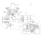
本実施形態の照明光学系4では、第1の実施形態に対して、赤色光Rおよび緑色光Gを透過させ、青色光Bを反射させる第2のダイクロイックミラー38が追加されている。第2のダイクロイックミラー38は、第1の光源10と反射ミラー31との間に配置されている。青色LED20は、この第2のダイクロイックミラー38に集光レンズ群29を介して青色光Bを入射するように配置されている。これにより、第2のダイクロイックミラー38は、3つの色光R,G,Bからなる合成光RGBを射出することができる。なお、本実施形態では、第1の実施形態における、第1のダイクロイックミラー37や、第2の光源(青色LED)20に付属した、集光レンズ以外の他の光学素子は設けられていない。また、射出光を特定の偏光成分の光に変換する必要がないため、第1の実施形態で設けられていた偏光変換素子(PSコンバータ35)も設けられていない。
In the illumination optical system 4 of the present embodiment, a second
本実施形態のDMDプロジェクタ3では、後述するように、いわゆる単板方式を用いてカラー画像を投影している。そのため、照明光学系4は、赤色光R、緑色光G、および青色光Bを、合成光RGBとして同一光路で射出するだけでなく、時分割して射出する必要がある。そのために、本実施形態では、液晶素子14のOFF状態とON状態の時間比率に応じて、レーザ光源ユニット11や青色LED20のON/OFFが時分割で切り替えられるように構成されている。カラー画像の各色成分に対するこれらの時分割動作パターンを、一例として、表1に示しておく。
As will be described later, the
ここで、本実施形態のDMDプロジェクタ3に用いたDMD61の構成について説明する。
Here, the configuration of the
図4(a)は、DMD61の構成を示す概略正面図であり、図4(b)は、図4(a)において点線で囲まれた領域付近を拡大して示す概略正面図である。
FIG. 4A is a schematic front view showing the configuration of the
DMD61は、マトリクス状に配列された多数の微小ミラー(画素)61aから構成され、図4(a)の矢印の方向から光が入射するように、DMDプロジェクタ3内に配置されている。各微小ミラー61aは、入射光と直交する軸61aを回転軸として±12°傾斜するように構成されている。微小ミラー61aの回転軸61aは、正方形状の各微小ミラー61の対角線方向であり、微小ミラー61aの配列方向に対して45°傾いている。
The
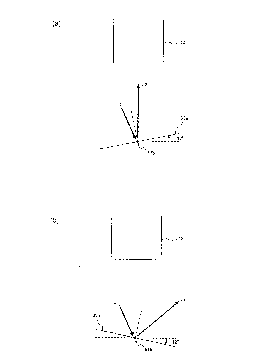
図5は、図4(b)のA−A’線に沿った概略断面図であり、図5(a)および図5(b)は、それぞれ+12°および−12°傾斜したときの微小ミラー61aを示している。なお、図5(a)および図5(b)には、各微小ミラー61aに対する投写レンズ52の配置も模式的に示されている。
FIG. 5 is a schematic cross-sectional view along the line AA ′ in FIG. 4B. FIGS. 5A and 5B are micromirrors when tilted by + 12 ° and −12 °, respectively. 61a is shown. 5A and 5B also schematically show the arrangement of the
微小ミラー61aは、+12°傾斜したときにON状態となる。すなわち、図5(a)に示すように、ON状態では、微小ミラー61に入射した光(図中矢印L1参照)は、投写レンズ52に入射できるような方向(図中矢印L2参照)に反射される。一方、−12°傾斜したときには、微小ミラー61aはOFF状態となる。すなわち、図5(b)に示すように、微小ミラー61aに入射した光(図中矢印L1参照)は、投写レンズ52に入射できない方向(図中矢印L3参照)に反射される。
The
このようにして、DMD61は、時分割で入射する各色光R,G,Bに同期して、各微小ミラー61aのON状態とOFF状態とを切り替えることで、投写レンズ52を通じてカラー画像を投影することができる。
In this way, the
最後に、再び図3を参照して、本実施形態のDMDプロジェクタ3で画像が投写される動作について説明する。
Finally, referring to FIG. 3 again, an operation of projecting an image by the
赤色光Rおよび緑色光Gは、第1の実施形態と同様に、第1の光源10から同一の光路で射出され、第2のダイクロイックミラー38に入射する。第2のダイクロイックミラー38には、青色LED20から射出された青色光Bも、集光レンズ群29を介して同様に入射する。
Similarly to the first embodiment, the red light R and the green light G are emitted from the
赤色光Rおよび緑色光Gが第2のダイクロイックミラー38を透過し、青色光Bが第2のダイクロイックミラー38を反射することで、3つの色光R,G,Bは、第2のダイクロイックミラー38によって合成される。合成された色光RGBは、反射ミラー31で反射した後、レンズアレイ33,34で照射分布が均一化され、集光レンズ36で集光されて、照明光学系4から射出される。
The red light R and the green light G are transmitted through the second
照明光学系4から射出された色光RGBは、反射ミラー63と集光レンズ64とを介して、TIRプリズム62に入射する。TIRプリズム62に入射した色光RGBは、TIRプリズム62内のエアギャップ面で反射して、DMD61に入射し、DMD61で画像信号に応じて変調される。変調された光は、TIRプリズム62を透過して、投写レンズ52へと入射し、投写レンズ52によってスクリーンなどに投写されて、画像として表示される。
The color light RGB emitted from the illumination optical system 4 enters the
1 液晶プロジェクタ
2,4 照明光学系
3 DMDプロジェクタ
10 第1の光源
11 レーザ光源ユニット
11a 青色レーザダイオード
11b コリメートレンズ
11c 機構部品
12 赤色蛍光体
13 緑色蛍光体
14 液晶素子
15 ダイクロイックプリズム
16,17,29 集光レンズ群
18 励起光生成手段
20 青色LED
21,23,27,36,45r,45g,45b,64 集光レンズ
22,31,44r,44g,44b,63 反射ミラー
24,25,33,34 レンズアレイ
26,35 PSコンバータ
37 第1のダイクロイックミラー
38 第2のダイクロイックミラー
40r,40g,40b 液晶ユニット
41r,41g,41b 液晶パネル
42r,42g,42b 入射側偏光板
40r,40g,40b 出射側偏光板
51 クロスダイクロイックプリズム
52 投写レンズ
61 DMD
62 TIRプリズムDESCRIPTION OF SYMBOLS 1
21, 23, 27, 36, 45r, 45g, 45b, 64
62 TIR Prism
Claims (8)
前記第1の光源が、
直線偏光のレーザ光を射出する半導体レーザ素子と、
前記半導体レーザ素子から射出された前記レーザ光を空間的および時間的に分離して、第1の励起光と第2の励起光とを生成する励起光生成手段と、
前記第1の励起光によって励起され、前記第1の色光を発する第1の蛍光体と、
前記第2の励起光によって励起され、前記第2の色光を発する第2の蛍光体と、
を有し、
前記励起光生成手段が、
入射する前記レーザ光を偏光方向が互いに直交する2つの光のいずれかに変換する液晶素子と、
前記液晶素子によって変換された前記2つの光を、その偏光方向の違いに応じて、前記第1の励起光と前記第2の励起光とに空間的に分離する光空間分離手段と、を有する、
照明光学系。An illumination optical system having a first light source that emits first color light and second color light, and a second light source that emits third color light,
The first light source is
A semiconductor laser element that emits linearly polarized laser light;
Excitation light generation means for generating the first excitation light and the second excitation light by spatially and temporally separating the laser light emitted from the semiconductor laser element;
A first phosphor that is excited by the first excitation light and emits the first color light;
A second phosphor that is excited by the second excitation light and emits the second color light;
Have
The excitation light generating means is
A liquid crystal element that converts the incident laser light into one of two lights whose polarization directions are orthogonal to each other;
An optical space separation unit that spatially separates the two light beams converted by the liquid crystal element into the first excitation light and the second excitation light according to a difference in polarization direction thereof. ,
Illumination optical system.
Applications Claiming Priority (1)
| Application Number | Priority Date | Filing Date | Title |
|---|---|---|---|
| PCT/JP2010/071992 WO2012077192A1 (en) | 2010-12-08 | 2010-12-08 | Lighting optical system and projection display device comprising same |
Publications (2)
| Publication Number | Publication Date |
|---|---|
| JPWO2012077192A1 JPWO2012077192A1 (en) | 2014-05-19 |
| JP5574459B2 true JP5574459B2 (en) | 2014-08-20 |
Family
ID=46206712
Family Applications (1)
| Application Number | Title | Priority Date | Filing Date |
|---|---|---|---|
| JP2012547625A Active JP5574459B2 (en) | 2010-12-08 | 2010-12-08 | Illumination optical system and projection display device including the same |
Country Status (5)
| Country | Link |
|---|---|
| US (1) | US20130242264A1 (en) |
| EP (1) | EP2650728A4 (en) |
| JP (1) | JP5574459B2 (en) |
| CN (1) | CN103261964B (en) |
| WO (1) | WO2012077192A1 (en) |
Families Citing this family (22)
| Publication number | Priority date | Publication date | Assignee | Title |
|---|---|---|---|---|
| JP2017129658A (en) * | 2016-01-19 | 2017-07-27 | セイコーエプソン株式会社 | Projector and method for controlling projector |
| JP5874058B2 (en) * | 2010-12-06 | 2016-03-01 | パナソニックIpマネジメント株式会社 | Light source device and projection display device |
| CN102789121A (en) * | 2012-04-10 | 2012-11-21 | 海信集团有限公司 | Projection display light source |
| JP5970994B2 (en) * | 2012-07-12 | 2016-08-17 | ソニー株式会社 | Light source device and projector |
| US9599316B2 (en) | 2012-09-10 | 2017-03-21 | Mitsubishi Electric Corporation | Light source device using monochromatic light to excite stationary phosphor layers |
| WO2014115492A1 (en) * | 2013-01-24 | 2014-07-31 | パナソニック株式会社 | Solid-state light source device |
| JP6245469B2 (en) * | 2013-09-20 | 2017-12-13 | カシオ計算機株式会社 | Light source unit and projector |
| WO2015145612A1 (en) * | 2014-03-26 | 2015-10-01 | Necディスプレイソリューションズ株式会社 | Light source device, projecting display device, and method for radiating illumination light to display element |
| WO2015149877A1 (en) | 2014-04-04 | 2015-10-08 | Barco Nv | Laser projection illumination system |
| CN105223761B (en) * | 2014-07-01 | 2017-05-24 | 中强光电股份有限公司 | Projection device and illumination system |
| JP6517008B2 (en) * | 2014-12-03 | 2019-05-22 | 株式会社小糸製作所 | Lighting unit |
| WO2016170966A1 (en) * | 2015-04-20 | 2016-10-27 | ソニー株式会社 | Light source device, projection display device, and display system |
| CN105425521A (en) * | 2015-12-23 | 2016-03-23 | 海信集团有限公司 | Light source device and image display device |
| CN105446064B (en) * | 2015-12-23 | 2017-10-03 | 海信集团有限公司 | Light supply apparatus and image display apparatus |
| CN105425522A (en) * | 2015-12-23 | 2016-03-23 | 海信集团有限公司 | Light source device and image display device |
| JP6418289B2 (en) * | 2017-07-07 | 2018-11-07 | ソニー株式会社 | projector |
| JP7022632B2 (en) * | 2018-03-27 | 2022-02-18 | シャープ株式会社 | Light source device, and projector device and lighting device using it |
| CN108957926A (en) * | 2018-07-18 | 2018-12-07 | 深圳市点睛创视技术有限公司 | A kind of photoluminescent light source |
| CN112526807A (en) * | 2019-08-30 | 2021-03-19 | 深圳光峰科技股份有限公司 | Light source and projection equipment |
| JP2022049267A (en) | 2020-09-16 | 2022-03-29 | セイコーエプソン株式会社 | Light source device and projector |
| CN114200754A (en) * | 2020-09-17 | 2022-03-18 | 深圳光峰科技股份有限公司 | Light source device and laser projection system |
| JP2022167694A (en) * | 2021-04-23 | 2022-11-04 | 株式会社リコー | Light guide optical device, light source device, and image projection device |
Citations (1)
| Publication number | Priority date | Publication date | Assignee | Title |
|---|---|---|---|---|
| JP2012113224A (en) * | 2010-11-26 | 2012-06-14 | Sanyo Electric Co Ltd | Illuminating device and projection type image displaying device |
Family Cites Families (23)
| Publication number | Priority date | Publication date | Assignee | Title |
|---|---|---|---|---|
| JPH11305192A (en) * | 1998-04-27 | 1999-11-05 | Sony Corp | Optical modulation element and image projection display |
| DE19924519A1 (en) * | 1999-04-12 | 2000-10-19 | Deutsche Telekom Ag | Method and device for reducing the formation of speckles on a projection screen |
| JP2003186110A (en) | 2001-12-21 | 2003-07-03 | Nec Viewtechnology Ltd | Led illumination dmd projector and optical system therefor |
| JP4184693B2 (en) * | 2002-04-04 | 2008-11-19 | シチズンホールディングス株式会社 | Polarization-controlled liquid crystal light modulator |
| JP3973477B2 (en) * | 2002-04-12 | 2007-09-12 | シャープ株式会社 | Image display device |
| JP4182804B2 (en) * | 2003-04-28 | 2008-11-19 | セイコーエプソン株式会社 | Illumination device and projection display device |
| US7083283B2 (en) * | 2003-07-22 | 2006-08-01 | Seiko Epson Corporation | Projector |
| JP2007108625A (en) * | 2004-12-07 | 2007-04-26 | Seiko Epson Corp | Illuminating apparatus and projector |
| JP4784262B2 (en) * | 2005-10-31 | 2011-10-05 | セイコーエプソン株式会社 | Illumination device and image display device |
| US20070187580A1 (en) * | 2006-02-14 | 2007-08-16 | Microvision, Inc. | Photoluminescent light sources, and scanned beam systems and methods of using same |
| US7997737B2 (en) * | 2006-04-12 | 2011-08-16 | Panasonic Corporation | Projection display device, and speckle reduction element |
| JP4304523B2 (en) * | 2006-05-26 | 2009-07-29 | ソニー株式会社 | Reflective liquid crystal projector and image reproducing apparatus |
| JP5152586B2 (en) * | 2008-09-30 | 2013-02-27 | カシオ計算機株式会社 | Light source device and projector |
| JP4692623B2 (en) * | 2008-12-17 | 2011-06-01 | カシオ計算機株式会社 | Light source device and light source control method |
| JP2010160444A (en) * | 2009-01-09 | 2010-07-22 | Nippon Hoso Kyokai <Nhk> | Video projector |
| JP4678556B2 (en) * | 2009-03-17 | 2011-04-27 | カシオ計算機株式会社 | Light emitting device, light source device, and projector using the light source device |
| JP4711154B2 (en) * | 2009-06-30 | 2011-06-29 | カシオ計算機株式会社 | Light source device and projector |
| JP5406638B2 (en) * | 2009-08-31 | 2014-02-05 | カシオ計算機株式会社 | Light source device and projector |
| JP5370764B2 (en) * | 2009-09-15 | 2013-12-18 | カシオ計算機株式会社 | Light source device and projector |
| JP5713168B2 (en) * | 2009-10-28 | 2015-05-07 | カシオ計算機株式会社 | Light source unit and projector |
| JP5770433B2 (en) * | 2010-06-18 | 2015-08-26 | ソニー株式会社 | Light source device and image projection device |
| JP2012014045A (en) * | 2010-07-02 | 2012-01-19 | Seiko Epson Corp | Projector |
| JP5311155B2 (en) * | 2010-12-14 | 2013-10-09 | カシオ計算機株式会社 | Light source device and projector |
-
2010
- 2010-12-08 CN CN201080070619.XA patent/CN103261964B/en not_active Expired - Fee Related
- 2010-12-08 JP JP2012547625A patent/JP5574459B2/en active Active
- 2010-12-08 WO PCT/JP2010/071992 patent/WO2012077192A1/en active Application Filing
- 2010-12-08 EP EP10860551.0A patent/EP2650728A4/en not_active Withdrawn
- 2010-12-08 US US13/988,505 patent/US20130242264A1/en not_active Abandoned
Patent Citations (1)
| Publication number | Priority date | Publication date | Assignee | Title |
|---|---|---|---|---|
| JP2012113224A (en) * | 2010-11-26 | 2012-06-14 | Sanyo Electric Co Ltd | Illuminating device and projection type image displaying device |
Also Published As
| Publication number | Publication date |
|---|---|
| WO2012077192A1 (en) | 2012-06-14 |
| US20130242264A1 (en) | 2013-09-19 |
| CN103261964A (en) | 2013-08-21 |
| EP2650728A1 (en) | 2013-10-16 |
| EP2650728A4 (en) | 2014-05-07 |
| CN103261964B (en) | 2015-09-02 |
| JPWO2012077192A1 (en) | 2014-05-19 |
Similar Documents
| Publication | Publication Date | Title |
|---|---|---|
| JP5574459B2 (en) | Illumination optical system and projection display device including the same | |
| JP5605866B2 (en) | Illumination optical system and projection display device including the same | |
| JP5874058B2 (en) | Light source device and projection display device | |
| US9081268B2 (en) | Lighting device and projection-type display apparatus including lighting device | |
| JP5914878B2 (en) | Light source device and projection display device | |
| JP2012133337A (en) | Light source device and projection display device | |
| JP2012128297A (en) | Light source device | |
| JP6406736B2 (en) | Projector and image display method | |
| WO2020230510A1 (en) | Image projection apparatus | |
| JP2018084757A (en) | Illumination apparatus and projector | |
| JP4183663B2 (en) | Illumination device and projection display device | |
| JP2018124538A (en) | Light source device and projection type display device | |
| JP2018054667A (en) | Light source device, and projection type picture display device | |
| JP2018031864A (en) | Illumination device and projector | |
| JP2014186080A (en) | Light source device and projection video display device | |
| US20220086407A1 (en) | Light source apparatus and projector | |
| JP2004226613A (en) | Illuminator and projection type video display device | |
| JP2017032631A (en) | Projector | |
| JP2019184628A (en) | Wavelength conversion element, light source device, and image projection device | |
| JP2012118129A (en) | Lighting unit and projection type video display device | |
| JP2012137705A (en) | Light source device | |
| JP5804536B2 (en) | Illumination optical system and projection display device | |
| JP4382503B2 (en) | Light source device for projection display device and projection display device | |
| JP4487484B2 (en) | LIGHTING DEVICE AND PROJECTOR HAVING THE SAME | |
| JP7108901B2 (en) | Lighting device and projection display device |
Legal Events
| Date | Code | Title | Description |
|---|---|---|---|
| RD04 | Notification of resignation of power of attorney |
Free format text: JAPANESE INTERMEDIATE CODE: A7424 Effective date: 20140516 |
|
| TRDD | Decision of grant or rejection written | ||
| A01 | Written decision to grant a patent or to grant a registration (utility model) |
Free format text: JAPANESE INTERMEDIATE CODE: A01 Effective date: 20140603 |
|
| A61 | First payment of annual fees (during grant procedure) |
Free format text: JAPANESE INTERMEDIATE CODE: A61 Effective date: 20140626 |
|
| R150 | Certificate of patent or registration of utility model |
Ref document number: 5574459 Country of ref document: JP Free format text: JAPANESE INTERMEDIATE CODE: R150 |
|
| S533 | Written request for registration of change of name |
Free format text: JAPANESE INTERMEDIATE CODE: R313533 |
|
| R350 | Written notification of registration of transfer |
Free format text: JAPANESE INTERMEDIATE CODE: R350 |