JP5574123B2 - Thoracic aortic stent graft with access region - Google Patents
Thoracic aortic stent graft with access region Download PDFInfo
- Publication number
- JP5574123B2 JP5574123B2 JP2011524987A JP2011524987A JP5574123B2 JP 5574123 B2 JP5574123 B2 JP 5574123B2 JP 2011524987 A JP2011524987 A JP 2011524987A JP 2011524987 A JP2011524987 A JP 2011524987A JP 5574123 B2 JP5574123 B2 JP 5574123B2
- Authority
- JP
- Japan
- Prior art keywords
- stent
- graft
- body portion
- tubular body
- tubes
- Prior art date
- Legal status (The legal status is an assumption and is not a legal conclusion. Google has not performed a legal analysis and makes no representation as to the accuracy of the status listed.)
- Active
Links
Images


Classifications
-
- A—HUMAN NECESSITIES
- A61—MEDICAL OR VETERINARY SCIENCE; HYGIENE
- A61F—FILTERS IMPLANTABLE INTO BLOOD VESSELS; PROSTHESES; DEVICES PROVIDING PATENCY TO, OR PREVENTING COLLAPSING OF, TUBULAR STRUCTURES OF THE BODY, e.g. STENTS; ORTHOPAEDIC, NURSING OR CONTRACEPTIVE DEVICES; FOMENTATION; TREATMENT OR PROTECTION OF EYES OR EARS; BANDAGES, DRESSINGS OR ABSORBENT PADS; FIRST-AID KITS
- A61F2/00—Filters implantable into blood vessels; Prostheses, i.e. artificial substitutes or replacements for parts of the body; Appliances for connecting them with the body; Devices providing patency to, or preventing collapsing of, tubular structures of the body, e.g. stents
- A61F2/02—Prostheses implantable into the body
- A61F2/04—Hollow or tubular parts of organs, e.g. bladders, tracheae, bronchi or bile ducts
- A61F2/06—Blood vessels
- A61F2/07—Stent-grafts
-
- A—HUMAN NECESSITIES
- A61—MEDICAL OR VETERINARY SCIENCE; HYGIENE
- A61F—FILTERS IMPLANTABLE INTO BLOOD VESSELS; PROSTHESES; DEVICES PROVIDING PATENCY TO, OR PREVENTING COLLAPSING OF, TUBULAR STRUCTURES OF THE BODY, e.g. STENTS; ORTHOPAEDIC, NURSING OR CONTRACEPTIVE DEVICES; FOMENTATION; TREATMENT OR PROTECTION OF EYES OR EARS; BANDAGES, DRESSINGS OR ABSORBENT PADS; FIRST-AID KITS
- A61F2/00—Filters implantable into blood vessels; Prostheses, i.e. artificial substitutes or replacements for parts of the body; Appliances for connecting them with the body; Devices providing patency to, or preventing collapsing of, tubular structures of the body, e.g. stents
- A61F2/82—Devices providing patency to, or preventing collapsing of, tubular structures of the body, e.g. stents
- A61F2/856—Single tubular stent with a side portal passage
-
- A—HUMAN NECESSITIES
- A61—MEDICAL OR VETERINARY SCIENCE; HYGIENE
- A61F—FILTERS IMPLANTABLE INTO BLOOD VESSELS; PROSTHESES; DEVICES PROVIDING PATENCY TO, OR PREVENTING COLLAPSING OF, TUBULAR STRUCTURES OF THE BODY, e.g. STENTS; ORTHOPAEDIC, NURSING OR CONTRACEPTIVE DEVICES; FOMENTATION; TREATMENT OR PROTECTION OF EYES OR EARS; BANDAGES, DRESSINGS OR ABSORBENT PADS; FIRST-AID KITS
- A61F2/00—Filters implantable into blood vessels; Prostheses, i.e. artificial substitutes or replacements for parts of the body; Appliances for connecting them with the body; Devices providing patency to, or preventing collapsing of, tubular structures of the body, e.g. stents
- A61F2/82—Devices providing patency to, or preventing collapsing of, tubular structures of the body, e.g. stents
- A61F2/86—Stents in a form characterised by the wire-like elements; Stents in the form characterised by a net-like or mesh-like structure
- A61F2/89—Stents in a form characterised by the wire-like elements; Stents in the form characterised by a net-like or mesh-like structure the wire-like elements comprising two or more adjacent rings flexibly connected by separate members
-
- A—HUMAN NECESSITIES
- A61—MEDICAL OR VETERINARY SCIENCE; HYGIENE
- A61F—FILTERS IMPLANTABLE INTO BLOOD VESSELS; PROSTHESES; DEVICES PROVIDING PATENCY TO, OR PREVENTING COLLAPSING OF, TUBULAR STRUCTURES OF THE BODY, e.g. STENTS; ORTHOPAEDIC, NURSING OR CONTRACEPTIVE DEVICES; FOMENTATION; TREATMENT OR PROTECTION OF EYES OR EARS; BANDAGES, DRESSINGS OR ABSORBENT PADS; FIRST-AID KITS
- A61F2/00—Filters implantable into blood vessels; Prostheses, i.e. artificial substitutes or replacements for parts of the body; Appliances for connecting them with the body; Devices providing patency to, or preventing collapsing of, tubular structures of the body, e.g. stents
- A61F2/02—Prostheses implantable into the body
- A61F2/04—Hollow or tubular parts of organs, e.g. bladders, tracheae, bronchi or bile ducts
- A61F2/06—Blood vessels
- A61F2002/061—Blood vessels provided with means for allowing access to secondary lumens
-
- A—HUMAN NECESSITIES
- A61—MEDICAL OR VETERINARY SCIENCE; HYGIENE
- A61F—FILTERS IMPLANTABLE INTO BLOOD VESSELS; PROSTHESES; DEVICES PROVIDING PATENCY TO, OR PREVENTING COLLAPSING OF, TUBULAR STRUCTURES OF THE BODY, e.g. STENTS; ORTHOPAEDIC, NURSING OR CONTRACEPTIVE DEVICES; FOMENTATION; TREATMENT OR PROTECTION OF EYES OR EARS; BANDAGES, DRESSINGS OR ABSORBENT PADS; FIRST-AID KITS
- A61F2/00—Filters implantable into blood vessels; Prostheses, i.e. artificial substitutes or replacements for parts of the body; Appliances for connecting them with the body; Devices providing patency to, or preventing collapsing of, tubular structures of the body, e.g. stents
- A61F2/02—Prostheses implantable into the body
- A61F2/04—Hollow or tubular parts of organs, e.g. bladders, tracheae, bronchi or bile ducts
- A61F2/06—Blood vessels
- A61F2002/065—Y-shaped blood vessels
- A61F2002/067—Y-shaped blood vessels modular
-
- A—HUMAN NECESSITIES
- A61—MEDICAL OR VETERINARY SCIENCE; HYGIENE
- A61F—FILTERS IMPLANTABLE INTO BLOOD VESSELS; PROSTHESES; DEVICES PROVIDING PATENCY TO, OR PREVENTING COLLAPSING OF, TUBULAR STRUCTURES OF THE BODY, e.g. STENTS; ORTHOPAEDIC, NURSING OR CONTRACEPTIVE DEVICES; FOMENTATION; TREATMENT OR PROTECTION OF EYES OR EARS; BANDAGES, DRESSINGS OR ABSORBENT PADS; FIRST-AID KITS
- A61F2/00—Filters implantable into blood vessels; Prostheses, i.e. artificial substitutes or replacements for parts of the body; Appliances for connecting them with the body; Devices providing patency to, or preventing collapsing of, tubular structures of the body, e.g. stents
- A61F2/02—Prostheses implantable into the body
- A61F2/04—Hollow or tubular parts of organs, e.g. bladders, tracheae, bronchi or bile ducts
- A61F2/06—Blood vessels
- A61F2/07—Stent-grafts
- A61F2002/075—Stent-grafts the stent being loosely attached to the graft material, e.g. by stitching
-
- A—HUMAN NECESSITIES
- A61—MEDICAL OR VETERINARY SCIENCE; HYGIENE
- A61F—FILTERS IMPLANTABLE INTO BLOOD VESSELS; PROSTHESES; DEVICES PROVIDING PATENCY TO, OR PREVENTING COLLAPSING OF, TUBULAR STRUCTURES OF THE BODY, e.g. STENTS; ORTHOPAEDIC, NURSING OR CONTRACEPTIVE DEVICES; FOMENTATION; TREATMENT OR PROTECTION OF EYES OR EARS; BANDAGES, DRESSINGS OR ABSORBENT PADS; FIRST-AID KITS
- A61F2/00—Filters implantable into blood vessels; Prostheses, i.e. artificial substitutes or replacements for parts of the body; Appliances for connecting them with the body; Devices providing patency to, or preventing collapsing of, tubular structures of the body, e.g. stents
- A61F2/82—Devices providing patency to, or preventing collapsing of, tubular structures of the body, e.g. stents
- A61F2002/821—Ostial stents
-
- A—HUMAN NECESSITIES
- A61—MEDICAL OR VETERINARY SCIENCE; HYGIENE
- A61F—FILTERS IMPLANTABLE INTO BLOOD VESSELS; PROSTHESES; DEVICES PROVIDING PATENCY TO, OR PREVENTING COLLAPSING OF, TUBULAR STRUCTURES OF THE BODY, e.g. STENTS; ORTHOPAEDIC, NURSING OR CONTRACEPTIVE DEVICES; FOMENTATION; TREATMENT OR PROTECTION OF EYES OR EARS; BANDAGES, DRESSINGS OR ABSORBENT PADS; FIRST-AID KITS
- A61F2250/00—Special features of prostheses classified in groups A61F2/00 - A61F2/26 or A61F2/82 or A61F9/00 or A61F11/00 or subgroups thereof
- A61F2250/0014—Special features of prostheses classified in groups A61F2/00 - A61F2/26 or A61F2/82 or A61F9/00 or A61F11/00 or subgroups thereof having different values of a given property or geometrical feature, e.g. mechanical property or material property, at different locations within the same prosthesis
- A61F2250/0039—Special features of prostheses classified in groups A61F2/00 - A61F2/26 or A61F2/82 or A61F9/00 or A61F11/00 or subgroups thereof having different values of a given property or geometrical feature, e.g. mechanical property or material property, at different locations within the same prosthesis differing in diameter
Landscapes
- Health & Medical Sciences (AREA)
- Engineering & Computer Science (AREA)
- Biomedical Technology (AREA)
- Heart & Thoracic Surgery (AREA)
- Oral & Maxillofacial Surgery (AREA)
- Transplantation (AREA)
- Cardiology (AREA)
- Vascular Medicine (AREA)
- Life Sciences & Earth Sciences (AREA)
- Animal Behavior & Ethology (AREA)
- General Health & Medical Sciences (AREA)
- Public Health (AREA)
- Veterinary Medicine (AREA)
- Pulmonology (AREA)
- Gastroenterology & Hepatology (AREA)
- Prostheses (AREA)
Description
本発明は、大動脈弓疾病の治療のための医療装置、より具体的には、その目的のために患者の胸部大動脈に展開するステント移植片に関する。 The present invention relates to medical devices for the treatment of aortic arch disease, and more particularly to a stent-graft that is deployed in a patient's thoracic aorta for that purpose.
近年、血管内植え込み型装置が大動脈瘤の治療のために開発されてきた。これらの装置は、観血的手術によるのではなく患者の脈管系を通して治療部位に送達される。該装置はチューブ状または筒状の、骨組みあるいはスカフォードの1つ以上のステントを含み、編まれたダクロン、ポリエステルポリテトラフルオロエチレンまたは同様のものなどのチューブ形状の移植片材料が該ステントに固定されている。該装置は、初めに小さい直径に縮小され、カテーテル送達システムの先端か近位端の中に配置され、その後、送達システムは大腿切開部を通すなど患者の脈管系に挿入される。送達システムの先端は予め配備されたガイドワイヤ上を治療部位まで操作される。植え込み型装置は、患者外部のシステムの遠位端からカテーテルの近位端まで延在する制御システムの操作を介して、その部位で該装置を保持し、周囲のシースを回収することによって配備される。次に、植え込み型装置かステント移植片は、自己拡張するか、またはステント移植片導入装置で導入されるバルーンの使用により拡張することができる。ステント移植片は大動脈の健康な壁組織の所定の位置に、例えば、棘で固定されるようになる。次に、送達システムは、血流が動脈瘤に入らないようにステント移植片を通して全血流を流す方法で、大動脈の動脈瘤を破棄するために所定の位置に可膨張式装置を残して取り外される。結果として、動脈瘤はもはや成長し続けて場合によっては破裂することがないだけでなく、動脈瘤が実際に縮まり始めて通例完全に見えなくなる。 In recent years, intravascular implantable devices have been developed for the treatment of aortic aneurysms. These devices are delivered to the treatment site through the patient's vasculature rather than by open surgery. The device includes one or more stents of tubular or tubular, skeleton or scaffolding, and a tubular shaped graft material such as knitted Dacron, polyester polytetrafluoroethylene or the like is secured to the stent. Has been. The device is first reduced to a small diameter and placed within the tip or proximal end of the catheter delivery system, after which the delivery system is inserted into the patient's vasculature, such as through a femoral incision. The tip of the delivery system is manipulated over a pre-deployed guidewire to the treatment site. The implantable device is deployed by holding the device at that site and retrieving the surrounding sheath via manipulation of a control system that extends from the distal end of the system external to the patient to the proximal end of the catheter. The The implantable device or stent-graft can then be self-expanded or expanded by use of a balloon introduced with the stent-graft introducer. The stent-graft becomes secured in place, for example with barbs, in a healthy wall tissue of the aorta. The delivery system then removes the inflatable device in place to discard the aortic aneurysm in a manner that allows the entire blood flow to flow through the stent-graft so that blood flow does not enter the aneurysm. It is. As a result, the aneurysm no longer continues to grow and possibly rupture, but the aneurysm actually begins to shrink and is usually completely invisible.
特に胸部大動脈瘤の治療のために、大動脈と大動脈の湾曲した強い血流があり得る領域の上部に、植え込み型装置を導入することが必要である。 In particular for the treatment of thoracic aortic aneurysms, it is necessary to introduce an implantable device in the upper part of the area where there can be strong curved blood flow in the aorta.
胸部大動脈には、主要分枝血管である、腕頭動脈、左頸動脈、および左鎖骨下動脈がある。胸部大動脈弓領域の動脈瘤の治療のために、これらの動脈に輸血をし続けなければならない。そのために、その領域でステント移植片の壁に窓が設けられる。左か右の上腕動脈を通して、あるいは、一般的ではないが左か右の頸動脈を通してステント移植片に側枝を配備するために、一般にこれらの窓にアクセスできる。そのような動脈を通して胸部大動脈弓に入ると、ステント移植片の窓にカテーテルを入れなければならない。これを簡素化するために、分岐血管が胸部大動脈弓に入る領域である胸部大動脈弓の外側に何らかの作業空間を有することが望ましい。 In the thoracic aorta are the main branch vessels, the brachiocephalic artery, left carotid artery, and left subclavian artery. In order to treat aneurysms in the thoracic aortic arch region, these arteries must continue to be transfused. To that end, a window is provided in the wall of the stent-graft in that region. These windows are generally accessible for deploying side branches to the stent-graft through the left or right brachial artery or, though less commonly, the left or right carotid artery. Upon entering the thoracic aortic arch through such an artery, a catheter must be placed in the stent-graft window. In order to simplify this, it is desirable to have some working space outside the thoracic aortic arch, which is the area where branch vessels enter the thoracic aortic arch.
この発明の目的は、上記の問題を克服するためのステント移植片の構成を提供するか、または少なくとも役に立つ別の手段を医師に提供することである。 It is an object of this invention to provide a stent-graft configuration to overcome the above problems, or at least provide another means to the physician to help.
本明細書中では、大動脈の部分、配備装置またはステント移植片などの人工器官に対する遠位という用語は、心臓からの血流の方向へさらに離れる側の、大動脈、配備装置またはステント移植片などの人工器官の端部を意味することを意図しており、近位という用語は、心臓により近い側の大動脈の部分、配備装置または人工器官の端部を意味することを意図している。人間又は動物の体内の他の管腔に対して、尾側と頭側という用語がそれぞれ理解されるべきである。 As used herein, the term distal to a prosthesis, such as aortic segment, deployment device or stent-graft, refers to the aorta, deployment device or stent-graft, etc., further away in the direction of blood flow from the heart. The term proximal is intended to mean the end of the prosthesis, and the term proximal is intended to mean the part of the aorta closer to the heart, the deployment device or the end of the prosthesis. The terms caudal and cranial should be understood with respect to other lumens in the human or animal body, respectively.
本明細書の全体を通して、「ステント移植片」という用語は、生体適合性移植片材料のチューブ状本体と、ステント移植片を貫通するルーメンを画定するためにチューブ状本体に固定された少なくとも1つのステントとを有する装置を意味することを意図している。ステント移植片は、分岐していてもよく、窓、側枝または同様のものを有していてもよい。ステント移植片の他の構成もまた本発明の範囲内のものである。 Throughout this specification, the term “stent graft” refers to a tubular body of biocompatible graft material and at least one secured to the tubular body to define a lumen through the stent graft. It is intended to mean a device having a stent. The stent-graft may be bifurcated and may have windows, side branches or the like. Other configurations of stent grafts are also within the scope of the present invention.
本発明の第1の態様によると、患者の胸部大動脈弓に配置するためのステント移植片であって、前記ステント移植片はルーメンを有する第1のチューブ状本体部分と、該第1のチューブ状本体部分より小さい直径を有する第2のチューブ状本体部分と、を備え、前記第2のチューブ状本体部分は側枝ステント移植片を収容するための少なくとも1つの開口部を有し、該少なくとも1つの開口部は、前記ステント移植片が配備中に湾曲したときに該湾曲の外側にまたは外側に隣接して位置する、ステント移植片が提供される。 According to a first aspect of the invention, a stent-graft for placement in a patient's thoracic aortic arch, the stent-graft having a first tubular body portion having a lumen, and the first tubular shape. A second tubular body portion having a smaller diameter than the body portion, the second tubular body portion having at least one opening for receiving a side branch stent graft, the at least one An opening is provided for the stent-graft that lies outside or adjacent to the curvature when the stent-graft is curved during deployment.
本発明によって、患者の胸部大動脈弓に配置するためのステント移植片が提供されることが理解できるであろう。使用時、第1の本体部分は患者の上行大動脈に配置され、第2の本体部分は胸部大動脈弓の近くで下行大動脈を下がって延在する。ステント移植片は、直径が減少し始める移植片の部分が、腕頭動脈のすぐ近位側にあり、且つ胸部大動脈弓の湾曲部の外側にあるように、配置することができる。第1と第2の部分の直径が異なることにより、この配置によって、ステント移植片の外側の開口領域が画定される。この開口領域は第2の部分の開口部の遠位側であり、その結果、血流が開口部を通ってその開口領域まで生じて、手術の進行中に主要血管に対して内部の分岐を通って血液循環が維持されることを可能にしている。ステント移植片のより遠位の第2の部分がより小さい直径のものであるので、作業空間が設けられ、その中で分枝動脈からのガイドワイヤが開口部に入るように向けられることにより、カテーテル法を可能にすることができる。次に、その分岐動脈に血流をもたらすために、それぞれの分岐動脈からステント移植片に側枝ステント移植片を配備できる。 It will be appreciated that the present invention provides a stent-graft for placement in a patient's thoracic aortic arch. In use, the first body portion is positioned in the patient's ascending aorta and the second body portion extends down the descending aorta near the thoracic aortic arch. The stent-graft can be positioned so that the portion of the graft that begins to decrease in diameter is just proximal to the brachiocephalic artery and outside the thoracic aortic arch curvature. Due to the different diameters of the first and second portions, this arrangement defines an open area outside the stent-graft. This open area is distal to the opening of the second part, so that blood flow occurs through the opening to the open area, making internal branches to the main blood vessel during the course of the surgery. Allowing blood circulation to be maintained. Since the more distal second portion of the stent-graft is of a smaller diameter, a working space is provided in which the guide wire from the branch artery is directed to enter the opening, Catheterization can be enabled. A side branch stent graft can then be deployed from each branch artery to the stent graft to provide blood flow to the branch artery.
一実施例では、縮小した直径の領域に単一の開口部を有するステント移植片は、1つの大動脈用脚伸長部を外科的バイパス手術で他の動脈に入れることもできる。開口部(または窓)は、縮径領域または空洞の主要な表面にあってもよい。 In one example, a stent-graft having a single opening in a reduced diameter region can have one aortic leg extension placed in another artery in a surgical bypass procedure. The opening (or window) may be in the reduced diameter region or the major surface of the cavity.
ステント移植片はさらに開口部から第1の本体部分に向かって延在する内部チューブを備えることができる。 The stent-graft can further comprise an inner tube extending from the opening toward the first body portion.
該内部チューブはその長さの少なくとも一部に沿って、第1の本体部分のルーメンに開口する少なくとも2つのより小さい内部チューブに分割することができる。 The inner tube can be divided along at least a portion of its length into at least two smaller inner tubes that open into the lumen of the first body portion.
該2つの分離したチューブが2つの大血管のための脚伸長を可能にする。 The two separate tubes allow leg extension for two large vessels.
該内部チューブはその長さの一部に沿って、第1の本体部分のルーメンに開口する3つのより小さい内部チューブに分割することができる。 The inner tube can be divided along its length into three smaller inner tubes that open into the lumen of the first body portion.
手術の間、この構成は、分枝動脈の1つからのガイドワイヤを内部チューブに向け、次により小さい内部チューブの1つに入るように向けることにより、カテーテル法ができるようになる作業空間を可能にする。 During surgery, this configuration directs a guidewire from one of the branch arteries to the inner tube and then into one of the smaller inner tubes, thereby creating a working space that allows catheterization. to enable.
本発明の更なる態様では、患者の胸部大動脈弓への配置用ステント移植片であって、患者の上行大動脈に配置するための第1のルーメンを有する第1のチューブ状本体部分と、胸部大動脈弓に沿い、下行大動脈を下がって延在し、第1のチューブ状本体部分より小さい直径である、第2のチューブ状本体部分とを有するステント移植片と、第1の本体部分と第2の本体部分の間の、第1の部分と第2の部分で接合されて連続している段差部分と、第1の本体部分の第1の側と、段差部分の第1の側と、第2の本体部分の第1の側とが実質的に一直線上になっており、それにより段差が本体部分の第1の側の反対側の第2の側に画定され、内部チューブが段差部分の開口部から第1の本体部分に向かって延在しており、該内部チューブは、その長さの一部に沿って、少なくとも2つのより小さい内部チューブに分割され、該少なくとも2つのより小さい内部チューブは第1のルーメンに開口している、ステント移植片が提供される。 In a further aspect of the invention, a stent graft for placement in a patient's thoracic aortic arch, the first tubular body portion having a first lumen for placement in the ascending aorta of the patient, and the thoracic aorta A stent graft having a second tubular body portion extending along the arch and down the descending aorta and having a smaller diameter than the first tubular body portion; a first body portion and a second body portion; A step part joined between the first part and the second part and continuing between the body parts, a first side of the first body part, a first side of the step part, and a second part The first side of the body portion is substantially in line with the first side of the body portion so that a step is defined on the second side opposite the first side of the body portion and the inner tube is open to the step portion. Extending from the portion toward the first body portion, the inner tube Along a portion of the, is divided into at least two smaller inner tube, two smaller inner tube said at least is open to the first lumen, the stent graft is provided.
第1のチューブ状本体部分と第2のチューブ状本体部分の少なくとも1つがそれに沿ってステントを備えている。好ましくは、チューブ状本体部分のそれぞれは、それに沿ってステントを備えている。該ステントは自己拡張式ステント、例えばジグザグ形の自己拡張式ステントを構成していることが望ましい。複数の自己拡張式ステントは、ステント移植片の柔軟性を許容するために、隣接しているステントの略軸線長さ分だけ長手方向に隔置することができる。ステント間の移植片材料は、ステント移植片の柔軟性を許容するために、波形を付けることができる。 At least one of the first tubular body portion and the second tubular body portion includes a stent along it. Preferably, each tubular body portion is provided with a stent along it. The stent preferably comprises a self-expanding stent, such as a zigzag self-expanding stent. Multiple self-expanding stents can be spaced longitudinally by the approximate axial length of adjacent stents to allow flexibility of the stent-graft. The graft material between the stents can be corrugated to allow the flexibility of the stent graft.
該ステント移植片は内側湾曲面と外側湾曲面によって長手方向に画定されている予め湾曲した形状に形成されており、第2の側面が外側湾曲面にあるようにすることができる。この場合、段差部分の開口部は湾曲部の外側にある。 The stent-graft may be formed in a pre-curved shape that is longitudinally defined by an inner curved surface and an outer curved surface, with the second side being on the outer curved surface. In this case, the opening of the step portion is outside the curved portion.
好ましい実施形態では、段差部分か縮径領域の開口部を湾曲部の外側の一方の側に置くことができる。この場合、開口部は、湾曲部の外側から隣接しているか、または中心からずれて位置している。 In a preferred embodiment, the stepped portion or the opening of the reduced diameter region can be placed on one side outside the curved portion. In this case, the opening is adjacent to the outside of the curved portion or is offset from the center.
典型的には、第1のチューブ状本体部分は35から50mmの直径を有することができる。第2のチューブ状本体部分は20から30mmの直径を有することができる。段差部分は10から30mmの幅を有することができる。内部チューブは、断面図では実質的に円形か楕円形であり得る。内部チューブは、15から20mmの直径を有することができる。2つのより小さい内部チューブがある場合では、該2つのより小さい内部チューブは、一例では、それぞれ10mmと12mmの直径を有することができる。 Typically, the first tubular body portion can have a diameter of 35 to 50 mm. The second tubular body portion can have a diameter of 20 to 30 mm. The step portion can have a width of 10 to 30 mm. The inner tube can be substantially circular or elliptical in cross section. The inner tube can have a diameter of 15 to 20 mm. In the case where there are two smaller inner tubes, the two smaller inner tubes, in one example, can have a diameter of 10 mm and 12 mm, respectively.
2つのより小さい内部チューブがあることが望ましい。3つのより小さい内部チューブ、すなわち、胸部大動脈弓の各大血管のためのものがあってもよい。 It is desirable to have two smaller inner tubes. There may be three smaller inner tubes, one for each large vessel of the thoracic aortic arch.
更なる実施形態では、より小さい内部チューブはそれぞれ6から10mmの範囲の直径を有している。別の実施形態では、2つのより小さい内部チューブの一方は6から8mmの範囲の直径を有しており、2つのより小さい内部チューブのもう一方が8から12mmの範囲の直径を有している。そのような状況では、該2つのより小さい内部チューブの打の大きい方が第1の部分の壁に隣接していることが望ましい。 In further embodiments, the smaller inner tubes each have a diameter in the range of 6 to 10 mm. In another embodiment, one of the two smaller inner tubes has a diameter in the range of 6 to 8 mm and the other of the two smaller inner tubes has a diameter in the range of 8 to 12 mm. . In such a situation, it is desirable for the larger of the two smaller inner tubes to be adjacent to the wall of the first portion.
本発明のさらなる態様によれば、開口部が腕頭動脈を有する大動脈の結合部のすぐ近位側に配置されるように、請求項1から28の何れかに記載のステント移植片を胸部大動脈弓に配備するステップを含む大動脈瘤の治療方法が提供される。 According to a further aspect of the present invention, the stent-graft according to any of claims 1 to 28, wherein the opening is located immediately proximal to the aortic junction with the brachiocephalic artery. A method for treating an aortic aneurysm comprising the step of deploying to an arch is provided.
本発明のさらなる態様によれば、段差部分が腕頭動脈を有する大動脈の結合部のすぐ近位側にあるように、請求項2から28の何れかに記載のステント移植片を胸部大動脈弓に配備するステップを含む、大動脈瘤の治療方法が提供される。 According to a further aspect of the present invention, the stent graft according to any of claims 2 to 28 is applied to the thoracic aortic arch so that the stepped portion is just proximal to the aortic junction with the brachiocephalic artery. A method of treating an aortic aneurysm is provided that includes a deploying step.
本発明の好ましい実施形態を、これより添付図面を参照して説明していく。 Preferred embodiments of the present invention will now be described with reference to the accompanying drawings.
次に図面、特に図1から4に示した実施形態をより詳しく見ていくと、ステント移植片2が、概ねダクロンなどの生体適合性の移植片材料のチューブ状本体4を備えていることが理解されるであろう。該チューブ状本体は3つの主要部分、すなわち、第1の部分6、第2の部分8、および第1の部分と第2の部分の間の段差部分10を備えるものとして見なすことができる。第1の部分6は患者の上行大動脈の壁に適合し係合する直径である。第1の部分は35から50mmの直径を有することができる。第2の部分8は第1の部分より小さい5から15mmの直径である。第1の部分の長さは20から60mmであってもよく、第2の部分の長さは80から150mmであってもよく、段差部分は10から30mmの長さであってもよい。段差部分10は第1と第2の部分のそれぞれの内側14と16とに整列した実質的にまっすぐな内側12を備えている。段差部分10は第1の部分の外側20から第2の部分の外側22まで延在する傾斜または先細りした外側18を備えている。
Turning now to the drawings, in particular the embodiment shown in FIGS. 1 to 4, in more detail, the stent-graft 2 comprises a tubular body 4 of generally biocompatible graft material such as Dacron. Will be understood. The tubular body can be considered as comprising three main parts: a
複数のジグザグ形ステント24はチューブ状本体のための支持体をその長さに沿って形成している。上行大動脈の壁に対して係合する滑らかな外側シール面を設けるために、ステント移植片の近位端26の内側に、ジグザグ形ステント24aがある。特に、第2の部分8において、ステント移植片の柔軟性で胸部大動脈弓と下行大動脈の形に合わせることができるように、ステントが隔置されている。この領域において、ステントは隣接しているステントの概ね軸線長さ分だけ隔置される。本実施形態では、ステント間の空間の移植材料は、ステント間の良好な柔軟性を与えるために波形構造28に形成され、更に構造的剛性をも与えている。ステント間の空間の移植材料は、螺旋状の補強ワイヤで補強することができる。移植材料のための螺旋状の補強は、「柔軟性のあるステント移植片(Flexible Stent Graft)」と題する米国特許出願第12/161,860号に示されており、その教示の全体を本明細書に援用する。
The plurality of zigzag stents 24 form a support for the tubular body along its length. A
段差部分10において、開口部30は、内部チューブ32が開口部からステント移植片の近位端26に向かって延在する状態で形成されている。陥凹部内の開口部からの短い距離で、内部チューブは、内部チューブ32からステント移植片の近位端26に向かってさらに延在する2つのより小さいチューブ34と36に分割される。
In the stepped
ステント移植片が患者の胸部大動脈弓に配置されるとき、段差部分は、使用中に腕頭動脈のすぐ近位側で胸部大動脈弓の湾曲部の外側に位置する。第1の部分6は上行大動脈の近位方向に延在しており、第2の部分8は下行大動脈の遠位方向に延在している。ステント移植片と段差部分10の開口部の遠位側の胸部大動脈弓の外側との間で画定された拡張領域が、第1と第2の部分の直径の違いによって画定され、その結果、手術の進行中に、主要血管に対して内部の分岐を通って血液循環が維持される。ステント移植片のより遠位の第2の部分がより小さい直径のものであるので、その拡張領域は作業空間を提供し、その中で主要分枝動脈からのガイドワイヤを操作して、開口部30と内部チューブ32と次により小さい内部チューブ34と36のうちの一方に入るように向けることにより、カテーテル法を可能とすることができる。次に、その分岐動脈に血流をもたらすために、それぞれの分岐動脈からより小さいチューブの1つに側枝ステント移植片を配備できる。
When the stent-graft is placed in the patient's thoracic aortic arch, the stepped portion is located just proximal to the brachiocephalic artery and out of the curvature of the thoracic aortic arch during use. The
ステント移植片の近位端26から見た図3Aで分かるように、より小さいチューブ34と36がそれらの近位端を対向するD字形に形成させ、各D字の真直ぐな部分を互いに接合38して、使用時にステント移植片にデッドゾーンがないようにしている。また、より小さいチューブ34と36は第1の部分の側壁の40で接合されている。図4Aは遠位端から見たステント移植片を示している。特に、内部チューブ32が2つのより小さいチューブ34と36まで縮小するのを理解することができる。
As can be seen in FIG. 3A viewed from the
また、より小さいチューブ34と36のそれぞれは、それらの長さに沿ってジグザグ形ステント42で支持されて、それらの近位端で補強リング44によって補強されている。
Each of the
図3Bと4Bは本発明の別の実施形態の近位端と遠位端のそれぞれから見た図を示す。この実施形態には、内部チューブ32から延在し、ステント移植片の近位端に向けられた3つのより小さい内部チューブ34、35、36がある。腕頭のそれぞれの左頸動脈と左鎖骨下動脈は、それぞれの分岐移植片を介してより小さいチューブの1つに接続できる。
3B and 4B show views from the proximal and distal ends, respectively, of another embodiment of the present invention. In this embodiment, there are three smaller
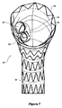
図5から図7はステント移植片の本発明による別の実施形態を示している。本実施形態では、ステント移植片50の本実施形態のチューブ状本体52が、第1の部分54、段差部分56、および第2の部分58を備えている。
Figures 5-7 show another embodiment of the stent graft according to the present invention. In the present embodiment, the tubular body 52 of the present embodiment of the stent-
第1の部分54は生体適合性移植片材料のチューブ状本体を備え、ジグザグ形ステント60を自己展開することによって支持されている。近位端においてステント60aは上行大動脈の壁に対して係合するために滑らかなシール面を設けるように内側にあり、ステント60bは外側にある。第1の部分は35から50mmの直径を有することができる。
The
さらに、第2の部分58が生体適合性移植片材料のチューブ状本体から形成され、ジグザグ形ステント68を自己展開することによって支持されている。第2の部分のチューブ状本体は、ステント68間の内側の湾曲部70よりも外側の湾曲部69のより大きい間隔によって部分的に曲がった形状に形成される。第2の部分58は30から40mmの範囲の直径を有することができる。
Further, the
さらに、段差部分56は、生体適合性移植片材料の切頭円錐形チューブ状本体から形成され、ジグザグ形ステント64と66を自己展開することによって支持されている。段差部分は、その近位端67に第1の部分の直径と実質的に同じ直径と、その遠位端に第2の部分の直径と実質的に同じ直径を有している。段差部分は、第1の部分の直径と第2の部分の直径の間の縮径分の全てをステント移植片の湾曲の外側72に有している。
Further, the
図5で具体的に理解できるように、段差部分56は、該段差部分内の陥凹部76に開口する窓74の開口部を有して、該陥凹部が第1の部分54に向かって近位方向に延在している。開口部はステント移植片の外側湾曲部からずれているので、該ステント移植片が胸部大動脈弓内に配置されるとき、該開口部は該胸部大動脈弓の腹側にわずかに開口する。大血管である、腕頭動脈、左頸動脈、および左鎖骨下動脈は、胸部大動脈弓から分岐して、胸部大動脈弓に対してわずかに腹側である。
As can be specifically understood in FIG. 5, the stepped
段差部分56内の陥凹部76は、その近位端で2つのチューブ78と80の中に開口している。それぞれのチューブは同じ直径のものであってもよく、上側のチューブ78が下側のチューブ80の直径より大きい直径を有していてもよい。チューブ78と80はステント移植片50の近位端61に向かって延在している。
A
より小さい内部チューブ78と80のそれぞれは螺旋形状記憶ワイヤ補強材83で補強することができる。移植材料のための螺旋状の補強は、「柔軟性のあるステント移植片(Flexible Stent Graft)」と題する米国特許出願第12/161,860号に示されており、その教示の全体を本明細書に援用する。
Each of the smaller
図8は本発明の一実施形態によるステント移植片の患者の胸部大動脈弓への配置の概略図を示す。 FIG. 8 shows a schematic view of placement of a stent-graft into a patient's thoracic aortic arch according to one embodiment of the present invention.
概略的に示した胸部大動脈弓は、胸部大動脈弓92にまで及ぶ上行大動脈90と胸部大動脈弓からの下行大動脈94を有している。実質的に、主要血管が、胸部大動脈弓の上端で、胸部大動脈弓から、わずかに胸部大動脈弓の腹側に分岐している。該主要血管は、腕頭動脈96、総頸動脈か左頸動脈98、および左鎖骨下動脈100である。予備手術では、接合部102が総頸動脈98と左鎖骨下動脈100の間に設けられる。接合部は総頸動脈98と左鎖骨下動脈100の間でアクセスを提供し、それは、より複雑であり得る左頸動脈を通す血管内アクセスではなく、左腕の上腕動脈を通すステント移植片への血管内アクセスを可能にする。
The thoracic aortic arch shown schematically has an ascending
ステント移植片106は、段差部分108が、腕頭動脈96がある大動脈の合流点にちょうど隣接するように胸部大動脈弓に配備される。これは、ステント移植片の配備操作とその後の側枝移植片の配置操作中に、内部チューブ78と80と陥凹部76(図6と図7参照)を通して主要血管に血液循環を維持できるように、段差部分と、胸部大動脈弓の上部壁とステント移植片109の第2の部分との間で拡張領域111が画定されることを意味している。また、該空間は内部チューブのカテーテル法ができるように支援する。破線110によって示されるように、カテーテルは、腕頭動脈96のための側枝ステント移植片114の配置を可能にするために、大きい方のチューブ78に入るように挿入することができ、また、破線112によって示されるように、カテーテルは、総頸動脈98と左鎖骨下動脈100のための側枝ステント移植片116の配置を可能にするために、小さい方のチューブ80に入るように挿入することができる。
The stent-
空間111が主要血管への血液循環の維持を可能にするので、急がずに手術を行える状況とすることができる。 Since the space 111 enables the blood circulation to the main blood vessels to be maintained, it is possible to make a situation where surgery can be performed without rushing.
好ましい実施形態では、大きい方の内部チューブ78は12mmの直径を有し、小さい方のチューブは10mmの直径を有している。
In the preferred embodiment, the larger
以上の記述と関連図面の教示の助けを借りて、当業者は本発明の多くの変更と他の実施形態を思いつくであろう。したがって、本発明が開示された特定の実施形態に限定されるものではなく、その変更と実施形態が附随の特許請求の範囲に包含されることを意図していることが理解される。 With the help of the above description and the teachings of the associated drawings, those skilled in the art will be able to conceive of many variations and other embodiments of the present invention. Therefore, it is to be understood that the invention is not limited to the specific embodiments disclosed, but that modifications and embodiments are intended to be included within the scope of the appended claims.
2、50、106、109、114、116 ステント移植片
4、52 チューブ状本体
6、54 第1の部分
8、58 第2の部分
10、56、108 段差部分
12、14、16 内側
18、20、22 外側
24、42、60、64、66、68 ジグザグ形ステント
26、61、67 近位端
28 波形構造
30 開口部
32 内部チューブ
34、35、36 より小さい内部チューブ
34、36 小さい内部チューブ
38 互いに接合
44 補強リング
68、60a ステント
69、70 湾曲部
72 外側
74 窓
76 陥凹部
78、80 チューブ
83 螺旋形状メモリワイヤ補強
90 上行大動脈
92 胸部大動脈弓
94 下行大動脈
96 腕頭動脈
98 頸動脈
100 左鎖骨下動脈
102 接合部
110、112 破線
111 拡張領域
2, 50, 106, 109, 114, 116 Stent graft 4, 52
Claims (24)
患者の上行大動脈の壁に適合し係合するように構成され且つルーメンを有する第1のチューブ状本体部分と、
該第1のチューブ状本体部分より小さい直径を有する第2のチューブ状本体部分と、
前記第1のチューブ状本体部分と前記第2のチューブ状本体部分とを連結している段差部分と、を備え、
前記段差部分は側枝ステント移植片を収容するための少なくとも1つの開口部を有し、
前記第1のチューブ状本体部分の第1の側と、前記第2のチューブ状本体部分の第1の側とが実質的に一直線状になっており、前記段差部分には前記第1及び第2のチューブ状本体部分の前記第1の側の反対側の第2の側に段差が画定され、
前記少なくとも1つの開口部は、前記ステント移植片が配備中に湾曲したときに該湾曲の外側にまたは外側に隣接して位置するように配置され、
前記少なくとも一つの開口部は陥凹部に連通し、該陥凹部は少なくとも2つのチューブに連通しており、
前記段差部分は10から30mmの長さを有する、ステント移植片。 A stent-graft for placement in a patient's thoracic aortic arch,
A first tubular body portion configured to fit and engage the wall of the patient's ascending aorta and having a lumen;
A second tubular body portion having a smaller diameter than the first tubular body portion;
A stepped portion connecting the first tubular main body portion and the second tubular main body portion,
The step portion has at least one opening for receiving a side branch stent-graft;
The first side of the first tubular body portion and the first side of the second tubular body portion are substantially straight, and the step portion includes the first and first A step is defined on the second side of the two tubular body portions opposite the first side;
The at least one opening is positioned to be located outside or adjacent to the bend when the stent-graft is bent during deployment;
The at least one opening communicates with a recess, the recess communicates with at least two tubes;
The stent-graft, wherein the stepped portion has a length of 10 to 30 mm.
The stent-graft is formed in a pre-curved shape that is longitudinally defined by an inner curved surface and an outer curved surface, and the at least one opening is offset from the center of the outer curved surface of the stent-graft. The stent-graft according to claim 1, wherein
Applications Claiming Priority (3)
| Application Number | Priority Date | Filing Date | Title |
|---|---|---|---|
| US19014108P | 2008-08-26 | 2008-08-26 | |
| US61/190,141 | 2008-08-26 | ||
| PCT/US2009/004827 WO2010024879A1 (en) | 2008-08-26 | 2009-08-25 | Thoracic aorta stent graft with access region |
Publications (3)
| Publication Number | Publication Date |
|---|---|
| JP2012501208A JP2012501208A (en) | 2012-01-19 |
| JP2012501208A5 JP2012501208A5 (en) | 2012-10-18 |
| JP5574123B2 true JP5574123B2 (en) | 2014-08-20 |
Family
ID=41212228
Family Applications (1)
| Application Number | Title | Priority Date | Filing Date |
|---|---|---|---|
| JP2011524987A Active JP5574123B2 (en) | 2008-08-26 | 2009-08-25 | Thoracic aortic stent graft with access region |
Country Status (5)
| Country | Link |
|---|---|
| US (5) | US9101456B2 (en) |
| EP (1) | EP2349085B1 (en) |
| JP (1) | JP5574123B2 (en) |
| AU (1) | AU2009286062B2 (en) |
| WO (1) | WO2010024879A1 (en) |
Cited By (1)
| Publication number | Priority date | Publication date | Assignee | Title |
|---|---|---|---|---|
| US11324583B1 (en) | 2021-07-06 | 2022-05-10 | Archo Medical LTDA | Multi-lumen stent-graft and related surgical methods |
Families Citing this family (86)
| Publication number | Priority date | Publication date | Assignee | Title |
|---|---|---|---|---|
| US7147661B2 (en) | 2001-12-20 | 2006-12-12 | Boston Scientific Santa Rosa Corp. | Radially expandable stent |
| US9597209B2 (en) * | 2005-02-17 | 2017-03-21 | Khoury Medical Devices, Llc | Vascular endograft |
| CA2679898C (en) | 2007-03-05 | 2014-11-18 | Alon Shalev | Multi-component expandable supportive bifurcated endoluminal grafts and methods for using same |
| CA2709278A1 (en) | 2007-12-15 | 2009-06-25 | Endospan Ltd. | Extra-vascular wrapping for treating aneurysmatic aorta in conjunction with endovascular stent-graft and methods thereof |
| US9226813B2 (en) | 2007-12-26 | 2016-01-05 | Cook Medical Technologies Llc | Low profile non-symmetrical stent |
| GB2476451A (en) | 2009-11-19 | 2011-06-29 | Cook William Europ | Stent Graft |
| US9180030B2 (en) | 2007-12-26 | 2015-11-10 | Cook Medical Technologies Llc | Low profile non-symmetrical stent |
| US8574284B2 (en) | 2007-12-26 | 2013-11-05 | Cook Medical Technologies Llc | Low profile non-symmetrical bare alignment stents with graft |
| EP2349085B1 (en) | 2008-08-26 | 2018-01-03 | Cook Medical Technologies LLC | Thoracic aorta stent graft with access region |
| US8506622B2 (en) | 2009-04-17 | 2013-08-13 | Medtronic Vascular, Inc. | Mobile external coupling for branch vessel connection |
| WO2010150208A2 (en) | 2009-06-23 | 2010-12-29 | Endospan Ltd. | Vascular prostheses for treating aneurysms |
| CA2767596C (en) | 2009-07-09 | 2015-11-24 | Endospan Ltd. | Apparatus for closure of a lumen and methods of using the same |
| US8474120B2 (en) * | 2009-10-09 | 2013-07-02 | W. L. Gore & Associates, Inc. | Bifurcated highly conformable medical device branch access |
| US9757263B2 (en) | 2009-11-18 | 2017-09-12 | Cook Medical Technologies Llc | Stent graft and introducer assembly |
| CN105361976B (en) | 2009-11-30 | 2017-08-18 | 恩多斯潘有限公司 | For implantation into the multi-part overlay film frame system in the blood vessel with multiple branches |
| WO2011070576A1 (en) | 2009-12-08 | 2011-06-16 | Endospan Ltd. | Endovascular stent-graft system with fenestrated and crossing stent-grafts |
| EP2519166A4 (en) | 2009-12-31 | 2017-06-14 | Endospan Ltd | Endovascular flow direction indicator |
| EP2533722B1 (en) | 2010-02-08 | 2017-03-29 | Endospan Ltd. | Thermal energy application for prevention and management of endoleaks in stent-grafts |
| AU2011215968B2 (en) | 2010-02-09 | 2013-08-01 | Cook Medical Technologies Llc | Thoracic aorta stent graft |
| AU2010201067B1 (en) * | 2010-03-19 | 2011-06-09 | Cook Incorporated | Thoracic stent graft |
| US8333800B2 (en) * | 2010-04-29 | 2012-12-18 | Medtronic Vascular, Inc. | Mobile external coupling with internal sealing cuff for branch vessel connection |
| AU2010202544B1 (en) * | 2010-06-18 | 2010-08-26 | Cook Incorporated | Side branch stent graft |
| US9566149B2 (en) * | 2010-11-16 | 2017-02-14 | W. L. Gore & Associates, Inc. | Devices and methods for in situ fenestration of a stent-graft at the site of a branch vessel |
| AU2010254599B1 (en) | 2010-12-15 | 2011-02-17 | Cook Incorporated | Hybrid Type A dissection device |
| EP2579810A4 (en) | 2011-02-03 | 2014-07-30 | Endospan Ltd | Implantable medical devices constructed of shape memory material |
| CN102641164B (en) * | 2011-02-16 | 2015-08-26 | 舒畅 | Branch type aortic stent vascular system |
| US9855046B2 (en) | 2011-02-17 | 2018-01-02 | Endospan Ltd. | Vascular bands and delivery systems therefor |
| EP2680788A4 (en) | 2011-03-02 | 2014-12-10 | Endospan Ltd | Reduced-strain extra- vascular ring for treating aortic aneurysm |
| EP3053545B1 (en) | 2011-04-28 | 2019-09-18 | Cook Medical Technologies LLC | Apparatus for facilitating deployment of an endoluminal prosthesis |
| US8574287B2 (en) | 2011-06-14 | 2013-11-05 | Endospan Ltd. | Stents incorporating a plurality of strain-distribution locations |
| WO2012176187A1 (en) | 2011-06-21 | 2012-12-27 | Endospan Ltd. | Endovascular system with circumferentially-overlapping stent-grafts |
| WO2013005207A1 (en) | 2011-07-07 | 2013-01-10 | Endospan Ltd. | Stent fixation with reduced plastic deformation |
| US9314328B2 (en) | 2011-08-16 | 2016-04-19 | W. L. Gore & Associates, Inc. | Branched stent graft device and deployment |
| US9839510B2 (en) | 2011-08-28 | 2017-12-12 | Endospan Ltd. | Stent-grafts with post-deployment variable radial displacement |
| US9662196B2 (en) | 2011-09-27 | 2017-05-30 | Cook Medical Technologies Llc | Endoluminal prosthesis with steerable branch |
| WO2013065040A1 (en) | 2011-10-30 | 2013-05-10 | Endospan Ltd. | Triple-collar stent-graft |
| BR112014011353A2 (en) * | 2011-11-11 | 2017-06-06 | Bolton Medical Inc | universal endovascular grafts |
| WO2013074990A1 (en) * | 2011-11-16 | 2013-05-23 | Bolton Medical, Inc. | Device and method for aortic branched vessel repair |
| WO2013084235A2 (en) | 2011-12-04 | 2013-06-13 | Endospan Ltd. | Branched stent-graft system |
| WO2013086132A1 (en) | 2011-12-06 | 2013-06-13 | Aortic Innovations Llc | Device for endovascular aortic repair and method of using the same |
| US10357353B2 (en) | 2012-04-12 | 2019-07-23 | Sanford Health | Combination double-barreled and debranching stent grafts and methods for use |
| US8702791B2 (en) | 2012-04-12 | 2014-04-22 | Sanford Health | Debranching visceral stent graft and methods for use |
| US9381101B2 (en) * | 2012-04-23 | 2016-07-05 | The Charlotte-Mecklenburg Hospital Authority | Hybrid graft for therapy of aortic pathology and associated method |
| US9737394B2 (en) * | 2012-04-27 | 2017-08-22 | Medtronic Vascular, Inc. | Stent-graft prosthesis for placement in the abdominal aorta |
| WO2013171730A1 (en) | 2012-05-15 | 2013-11-21 | Endospan Ltd. | Stent-graft with fixation elements that are radially confined for delivery |
| SG11201504463SA (en) | 2012-12-14 | 2015-07-30 | Sanford Health | Combination double-barreled and debranching stent grafts |
| US9861466B2 (en) * | 2012-12-31 | 2018-01-09 | Cook Medical Technologies Llc | Endoluminal prosthesis |
| WO2014108895A2 (en) | 2013-01-08 | 2014-07-17 | Endospan Ltd. | Minimization of stent-graft migration during implantation |
| US9668892B2 (en) | 2013-03-11 | 2017-06-06 | Endospan Ltd. | Multi-component stent-graft system for aortic dissections |
| US9993330B2 (en) * | 2013-03-13 | 2018-06-12 | Cook Medical Technologies Llc | Endoluminal prosthesis system |
| US9402751B2 (en) | 2013-03-13 | 2016-08-02 | W. L. Gore & Associates, Inc. | Devices and methods for treatment of the aortic arch |
| WO2014197839A2 (en) | 2013-06-07 | 2014-12-11 | Cedars-Sinai Medical Center | Vascular graft device placement system and method |
| US20150119975A1 (en) * | 2013-10-24 | 2015-04-30 | The Cleveland Clinic Foundation | Branched vessel prosthesis for repair of a failed stent graft |
| WO2015075708A1 (en) | 2013-11-19 | 2015-05-28 | Endospan Ltd. | Stent system with radial-expansion locking |
| US20170007392A1 (en) * | 2014-01-23 | 2017-01-12 | Biokyra Pesquisa E Desenvolvimento Ltda. | Endoprosthesis for endovascular treatment of thoracic-abdominal aortic aneurysms or dissections and endoprosthesis for endovascular treatment of abdominal aortic aneurysms or dissections which compromise the iliac arteries |
| CN104116577B (en) * | 2014-06-27 | 2017-07-14 | 先健科技(深圳)有限公司 | Branch type overlay film frame |
| ES2731434T3 (en) | 2014-09-23 | 2019-11-15 | Bolton Medical Inc | Vascular repair devices |
| KR101651148B1 (en) * | 2014-10-31 | 2016-09-05 | 주식회사 엠아이텍 | Endoscope Guide Stent |
| US10485684B2 (en) | 2014-12-18 | 2019-11-26 | Endospan Ltd. | Endovascular stent-graft with fatigue-resistant lateral tube |
| WO2016205826A1 (en) * | 2015-06-18 | 2016-12-22 | Aortic Innovations, Llc | Branched aortic graft and method of using the same |
| US10368977B2 (en) | 2015-12-29 | 2019-08-06 | Cook Medical Technologies Llc | Endograft with at least two branch portions |
| DE102015123000A1 (en) * | 2015-12-30 | 2017-07-06 | Jotec Gmbh | Self-expanding vascular prosthesis |
| US10512533B1 (en) | 2016-02-23 | 2019-12-24 | W. L. Gore & Associates, Inc. | Branched graft assembly method in vivo |
| US10390932B2 (en) | 2016-04-05 | 2019-08-27 | Bolton Medical, Inc. | Stent graft with internal tunnels and fenestrations and methods of use |
| ES2905193T3 (en) | 2016-05-25 | 2022-04-07 | Bolton Medical Inc | Stent grafts for the treatment of aneurysms |
| US10537419B2 (en) * | 2016-10-27 | 2020-01-21 | Cook Medical Technologies Llc | Prosthesis with branched portion |
| DE102016122223A1 (en) * | 2016-11-18 | 2018-05-24 | Bentley Innomed Gmbh | Multi-lumen implant |
| US11446168B2 (en) | 2017-04-25 | 2022-09-20 | Cook Medical Technologies Llc | Prosthesis with side branch and method of making the same |
| WO2019010458A1 (en) | 2017-07-07 | 2019-01-10 | Endologix, Inc. | Endovascular graft systems and methods for deployment in main and branch arteries |
| US10660770B2 (en) | 2017-07-18 | 2020-05-26 | Cook Medical Technologies Llc | Method of making an internal bidirectional branch |
| DE102017120819A1 (en) | 2017-09-08 | 2019-03-14 | Jotec Gmbh | Intraluminal vascular prosthesis system |
| US11304832B2 (en) * | 2018-04-23 | 2022-04-19 | Washington University | Fenestrated stent system and method of use |
| US11304794B2 (en) | 2018-06-19 | 2022-04-19 | Medtronic Vascular, Inc. | Modular stent device for multiple vessels and method |
| US11484423B2 (en) | 2018-08-21 | 2022-11-01 | Cook Medical Technologies Llc | Apparatuses to facilitate prosthesis placement |
| CN109009563B (en) * | 2018-08-27 | 2024-01-23 | 复旦大学附属中山医院 | Improved aortic arch tectorial membrane stent type blood vessel |
| CN109730805B (en) * | 2018-12-17 | 2021-07-20 | 深圳市先健畅通医疗有限公司 | Branch type blood vessel support |
| CN209808643U (en) * | 2019-01-31 | 2019-12-20 | 陈宏伟 | Aorta stent type blood vessel |
| US11083605B2 (en) | 2019-03-28 | 2021-08-10 | Medtronic Vascular, Inc. | Femoral aortic access modular stent assembly and method |
| US11116650B2 (en) | 2019-03-28 | 2021-09-14 | Medtronic Vascular, Inc. | Supra aortic access modular stent assembly and method |
| US11096775B2 (en) | 2019-07-03 | 2021-08-24 | Medtronic Vascular, Inc. | Single multibranch stent device assembly and method |
| US11826226B2 (en) | 2019-07-31 | 2023-11-28 | Medtronic Vascular, Inc. | Modular multibranch stent assembly and method |
| US11191633B2 (en) | 2019-08-29 | 2021-12-07 | Medtronic Vascular, Inc. | Modular multibranch stent assembly and method |
| US11324582B2 (en) | 2019-09-27 | 2022-05-10 | Medtronic Vascular, Inc. | Docking graft for placement of parallel distally extending grafts assembly and method |
| US20210106444A1 (en) * | 2019-10-15 | 2021-04-15 | Merit Medical Systems, Inc. | Endovascular prosthesis with selectively openable internal duct |
| CN110974484A (en) * | 2019-12-10 | 2020-04-10 | 北京理工大学 | Endoluminal prosthetic device for optimizing branch blood flow distribution |
| CN117042725A (en) * | 2021-02-22 | 2023-11-10 | W.L.戈尔及同仁股份有限公司 | Multi-branched intravascular devices and methods |
Family Cites Families (12)
| Publication number | Priority date | Publication date | Assignee | Title |
|---|---|---|---|---|
| US5360443A (en) * | 1990-06-11 | 1994-11-01 | Barone Hector D | Aortic graft for repairing an abdominal aortic aneurysm |
| US6814752B1 (en) | 2000-03-03 | 2004-11-09 | Endovascular Technologies, Inc. | Modular grafting system and method |
| EP1245202B1 (en) | 2001-03-27 | 2004-08-04 | William Cook Europe ApS | An aortic graft device |
| AUPR847301A0 (en) * | 2001-10-26 | 2001-11-15 | Cook Incorporated | Endoluminal prostheses for curved lumens |
| CA2474978C (en) * | 2002-03-25 | 2010-07-06 | Cook Incorporated | Bifurcated/branch vessel prosthesis |
| JP2004298548A (en) | 2003-04-01 | 2004-10-28 | Ube Ind Ltd | Tubular artificial organ |
| WO2005032340A2 (en) * | 2003-09-29 | 2005-04-14 | Secant Medical, Llc | Integral support stent graft assembly |
| US7828837B2 (en) | 2005-02-17 | 2010-11-09 | Khoury Medical Devices, LLC. | Vascular endograft |
| WO2008021557A1 (en) * | 2006-08-18 | 2008-02-21 | William A. Cook Australia Pty. Ltd. | Stent graft |
| EP2450006B1 (en) | 2007-08-08 | 2015-01-14 | The Cleveland Clinic Foundation | Branched stent graft system |
| US9107741B2 (en) | 2007-11-01 | 2015-08-18 | Cook Medical Technologies Llc | Flexible stent graft |
| EP2349085B1 (en) * | 2008-08-26 | 2018-01-03 | Cook Medical Technologies LLC | Thoracic aorta stent graft with access region |
-
2009
- 2009-08-25 EP EP09789202.0A patent/EP2349085B1/en active Active
- 2009-08-25 WO PCT/US2009/004827 patent/WO2010024879A1/en active Application Filing
- 2009-08-25 AU AU2009286062A patent/AU2009286062B2/en active Active
- 2009-08-25 JP JP2011524987A patent/JP5574123B2/en active Active
- 2009-08-25 US US13/061,065 patent/US9101456B2/en active Active
-
2015
- 2015-07-07 US US14/793,004 patent/US9655711B2/en active Active
-
2017
- 2017-04-14 US US15/487,752 patent/US10285799B2/en active Active
-
2019
- 2019-04-01 US US16/371,720 patent/US11071636B2/en active Active
-
2021
- 2021-07-20 US US17/380,321 patent/US11452590B2/en active Active
Cited By (1)
| Publication number | Priority date | Publication date | Assignee | Title |
|---|---|---|---|---|
| US11324583B1 (en) | 2021-07-06 | 2022-05-10 | Archo Medical LTDA | Multi-lumen stent-graft and related surgical methods |
Also Published As
| Publication number | Publication date |
|---|---|
| AU2009286062B2 (en) | 2013-07-18 |
| US10285799B2 (en) | 2019-05-14 |
| AU2009286062A1 (en) | 2010-03-04 |
| US20220110771A1 (en) | 2022-04-14 |
| US20110257731A1 (en) | 2011-10-20 |
| US20150305852A1 (en) | 2015-10-29 |
| US9655711B2 (en) | 2017-05-23 |
| US20170216013A1 (en) | 2017-08-03 |
| US11071636B2 (en) | 2021-07-27 |
| JP2012501208A (en) | 2012-01-19 |
| US20190239999A1 (en) | 2019-08-08 |
| EP2349085B1 (en) | 2018-01-03 |
| EP2349085A1 (en) | 2011-08-03 |
| US11452590B2 (en) | 2022-09-27 |
| WO2010024879A1 (en) | 2010-03-04 |
| US9101456B2 (en) | 2015-08-11 |
Similar Documents
| Publication | Publication Date | Title |
|---|---|---|
| JP5574123B2 (en) | Thoracic aortic stent graft with access region | |
| US11529225B2 (en) | Thoracic aorta stent graft | |
| EP2051663B1 (en) | Stent graft | |
| JP5651183B2 (en) | Paraplegia preventive stent graft | |
| CN103732282A (en) | Guidewire with two flexible end portions and method of accessing a branch vessel therewith | |
| EP2823788B1 (en) | An iliac stent graft | |
| US20170086993A1 (en) | Modular system with at least one branch graft |
Legal Events
| Date | Code | Title | Description |
|---|---|---|---|
| A521 | Request for written amendment filed |
Free format text: JAPANESE INTERMEDIATE CODE: A523 Effective date: 20120823 |
|
| A621 | Written request for application examination |
Free format text: JAPANESE INTERMEDIATE CODE: A621 Effective date: 20120823 |
|
| A521 | Request for written amendment filed |
Free format text: JAPANESE INTERMEDIATE CODE: A523 Effective date: 20120903 |
|
| A711 | Notification of change in applicant |
Free format text: JAPANESE INTERMEDIATE CODE: A711 Effective date: 20120914 |
|
| A521 | Request for written amendment filed |
Free format text: JAPANESE INTERMEDIATE CODE: A821 Effective date: 20120914 |
|
| A131 | Notification of reasons for refusal |
Free format text: JAPANESE INTERMEDIATE CODE: A131 Effective date: 20130814 |
|
| A521 | Request for written amendment filed |
Free format text: JAPANESE INTERMEDIATE CODE: A523 Effective date: 20131114 |
|
| A131 | Notification of reasons for refusal |
Free format text: JAPANESE INTERMEDIATE CODE: A131 Effective date: 20140108 |
|
| A521 | Request for written amendment filed |
Free format text: JAPANESE INTERMEDIATE CODE: A523 Effective date: 20140314 |
|
| TRDD | Decision of grant or rejection written | ||
| A01 | Written decision to grant a patent or to grant a registration (utility model) |
Free format text: JAPANESE INTERMEDIATE CODE: A01 Effective date: 20140520 |
|
| A711 | Notification of change in applicant |
Free format text: JAPANESE INTERMEDIATE CODE: A711 Effective date: 20140613 |
|
| A61 | First payment of annual fees (during grant procedure) |
Free format text: JAPANESE INTERMEDIATE CODE: A61 Effective date: 20140617 |
|
| A521 | Request for written amendment filed |
Free format text: JAPANESE INTERMEDIATE CODE: A821 Effective date: 20140613 |
|
| R150 | Certificate of patent or registration of utility model |
Ref document number: 5574123 Country of ref document: JP Free format text: JAPANESE INTERMEDIATE CODE: R150 |
|
| R250 | Receipt of annual fees |
Free format text: JAPANESE INTERMEDIATE CODE: R250 |
|
| R250 | Receipt of annual fees |
Free format text: JAPANESE INTERMEDIATE CODE: R250 |
|
| R250 | Receipt of annual fees |
Free format text: JAPANESE INTERMEDIATE CODE: R250 |
|
| R250 | Receipt of annual fees |
Free format text: JAPANESE INTERMEDIATE CODE: R250 |
|
| R250 | Receipt of annual fees |
Free format text: JAPANESE INTERMEDIATE CODE: R250 |
|
| R250 | Receipt of annual fees |
Free format text: JAPANESE INTERMEDIATE CODE: R250 |
|
| R250 | Receipt of annual fees |
Free format text: JAPANESE INTERMEDIATE CODE: R250 |