JP5572023B2 - measuring device - Google Patents
measuring device Download PDFInfo
- Publication number
- JP5572023B2 JP5572023B2 JP2010167728A JP2010167728A JP5572023B2 JP 5572023 B2 JP5572023 B2 JP 5572023B2 JP 2010167728 A JP2010167728 A JP 2010167728A JP 2010167728 A JP2010167728 A JP 2010167728A JP 5572023 B2 JP5572023 B2 JP 5572023B2
- Authority
- JP
- Japan
- Prior art keywords
- probe
- scanning
- measurement
- maintaining member
- shape maintaining
- Prior art date
- Legal status (The legal status is an assumption and is not a legal conclusion. Google has not performed a legal analysis and makes no representation as to the accuracy of the status listed.)
- Expired - Fee Related
Links
Images

Landscapes
- Ultra Sonic Daignosis Equipment (AREA)
Description
本発明は、超音波を送受信する探触子を用いることにより癌などの診断を行う超音波診断装置、光音響を利用して診断画像を撮像する光音響診断装置等の、測定対象内を伝播した音響波を受信して画像データなどを生成する測定装置及び測定方法に関する。本明細書において、音響波とは、音波、超音波、光音響波と呼ばれるものを含み、例えば、測定対象内部に近赤外線等の光(電磁波)を照射して測定対象内部で発生する音響波や、測定対象内部に音響波を送信して測定対象内部で反射した反射音響波を含む。 The present invention propagates within a measurement target such as an ultrasonic diagnostic apparatus that diagnoses cancer and the like by using a probe that transmits and receives ultrasonic waves, and a photoacoustic diagnostic apparatus that captures a diagnostic image using photoacoustics. The present invention relates to a measuring apparatus and a measuring method for receiving imaged acoustic waves and generating image data and the like. In this specification, an acoustic wave includes what is called a sound wave, an ultrasonic wave, and a photoacoustic wave. For example, an acoustic wave generated inside a measurement target by irradiating the measurement target with light (electromagnetic waves) such as near infrared rays. Or a reflected acoustic wave that is transmitted inside the measurement object and reflected inside the measurement object.
探触子を用いることにより癌などの診断を行う測定装置は、医療分野において広く利用されている。近年、探触子を有する測定装置を集団検診の様なスクリーニング検診に適用する為に、術者依存性の低減及び検査時間の短縮が求められている。この為の提案として、測定対象となる臓器に関して、輪郭等の境界線付近での探触子の走査密度を高密度、他の領域での探触子の走査密度を低密度にすることにより、検査時間を短縮する方法が開示されている(特許文献1参照)。しかしながら、この方法の場合、探触子の走査領域は全ての被験者において同一である。このため、乳癌のスクリーニング診断の様に被験者により測定対象が異なる場合、探触子は測定対象の存在しない領域も走査することになり、検査時間が冗長になる場合もあると考えられる。 A measuring apparatus that diagnoses cancer or the like by using a probe is widely used in the medical field. In recent years, in order to apply a measuring device having a probe to screening screening such as group screening, reduction of operator dependency and reduction of inspection time are required. As a proposal for this, regarding the organ to be measured, by making the scanning density of the probe near the boundary line such as the contour high, and by making the scanning density of the probe in other regions low, A method for shortening the inspection time is disclosed (see Patent Document 1). However, in this method, the scanning area of the probe is the same for all subjects. For this reason, when the measurement object differs depending on the subject as in the case of screening diagnosis of breast cancer, the probe also scans a region where the measurement object does not exist, and the examination time may be redundant.
また、測定対象を固定するための保持板などの形状維持部材を備える場合がある。こうした場合、形状維持部材により測定対象を保持しながら、装置として決められた走査領域をフルサイズで撮像すると、測定対象の有無に関わらず形状維持部材の表面の全走査領域に亘って計測動作を完遂するため、診断毎に一律の時間を要することになる。同時に、必要以上に被験者に負担を負わせることになる。 In some cases, a shape maintaining member such as a holding plate for fixing the measurement target is provided. In such a case, if the scanning area determined as the device is captured in full size while holding the measurement object by the shape maintaining member, the measurement operation is performed over the entire scanning area on the surface of the shape maintaining member regardless of the presence or absence of the measurement object. To complete, a uniform time is required for each diagnosis. At the same time, the subject is burdened more than necessary.
上記課題に鑑み、本発明は、測定対象を保持しながら測定を行う装置及び方法において、受信信号の特性に基づき測定対象の有無を判定して測定対象毎に、例えば、探触子の走査態様、信号処理態様等を調整することで、測定時間を短縮可能とすることを目的とする。 In view of the above problems, the present invention provides an apparatus and method for performing measurement while holding a measurement target, and for determining the presence or absence of the measurement target based on the characteristics of the received signal, for example, a scanning mode of a probe. It is an object to make it possible to shorten the measurement time by adjusting the signal processing mode and the like.
上記課題に鑑み、形状維持部材で保持された測定対象を測定する本発明の測定装置は、探触子と記憶部と判定手段を有し、前記判定手段による判定に基づき、当該測定装置の測定動作を制御する。前記探触子は、前記形状維持部材で保持された測定対象からの音響波を前記形状維持部材を介して受信し電気信号に変換するための電気機械変換装置を有し、前記形状維持部材の表面に沿って走査される。前記記憶部は、前記受信信号を格納する。前記判定手段は、前記記憶部に格納された受信信号に基づき、前記探触子が前記測定対象の存在する前記形状維持部材の表面領域を走査しているか否かを判定する。 In view of the above problems, a measurement apparatus according to the present invention for measuring a measurement object held by a shape maintaining member has a probe, a storage unit, and a determination unit. Based on the determination by the determination unit, the measurement apparatus measures Control the behavior. The probe includes an electromechanical converter for receiving an acoustic wave from a measurement object held by the shape maintaining member through the shape maintaining member and converting the acoustic wave into an electric signal. It is scanned along the surface. The storage unit stores the received signal. The determination unit determines whether or not the probe is scanning the surface region of the shape maintaining member where the measurement target exists based on the received signal stored in the storage unit.
また、上記課題に鑑み、形状維持部材で保持された測定対象を測定する本発明の測定方法は、次の工程を有する。前記形状維持部材で保持された測定対象からの音響波を前記形状維持部材を介して受信し電気信号に変換するための電気機械変換装置を有する探触子を前記形状維持部材の表面に沿って走査する工程。前記受信信号を格納する工程。前記格納された受信信号に基づき、前記探触子が前記測定対象の存在する前記形状維持部材の表面領域を走査しているか否かを判定する工程。前記判定に基づき、当該測定方法の測定態様を制御する工程。 Moreover, in view of the said subject, the measuring method of this invention which measures the measuring object hold | maintained with the shape maintenance member has the following process. A probe having an electromechanical transducer for receiving an acoustic wave from a measurement object held by the shape maintaining member via the shape maintaining member and converting the acoustic wave into an electric signal is provided along the surface of the shape maintaining member. Scanning. Storing the received signal. Determining whether or not the probe is scanning the surface region of the shape maintaining member on which the measurement target exists based on the stored received signal; Controlling the measurement mode of the measurement method based on the determination.
本発明によれば、探触子の走査領域において形状維持部材で保持された測定対象の有無の判定に基づき適宜に測定態様の制御が行われ(例えば、探触子の走査の制御など)、各測定対象に対して適切な測定が可能となって測定時間を短縮することができる。 According to the present invention, the measurement mode is appropriately controlled based on the determination of the presence / absence of the measurement target held by the shape maintaining member in the scanning region of the probe (for example, the scanning control of the probe, etc.) Appropriate measurement is possible for each measurement object, and the measurement time can be shortened.
本発明の特徴は、形状維持部材で保持された測定対象からの音響波を受信する探触子が測定対象の存在する形状維持部材の表面領域を走査しているか否かを音響波の受信信号に基づき判定し、該判定に基づき、測定態様を制御することにある。この考え方に基づき、本発明の測定装置及び方法は、上記課題を解決するための手段のところで述べた様な基本的な構成を有する。より具体的な実施の形態としては、以下に述べる様なものが可能である。 A feature of the present invention is that an acoustic wave reception signal indicates whether or not a probe that receives an acoustic wave from a measurement object held by the shape maintenance member is scanning the surface region of the shape maintenance member where the measurement object exists. The measurement mode is controlled based on the determination. Based on this idea, the measuring apparatus and method of the present invention have the basic configuration as described in the means for solving the above problems. More specific embodiments are possible as described below.
探触子が備える電気機械変換装置は、少なくとも音響波を受信可能であればよい。電気機械変換装置が音響波の送信機能と受信機能を有する場合は、電気機械変換装置は、生体などの測定対象に対して音響波を発すると共に、測定対象からの音響波の反射波を受信する。電気機械変換装置が音響波の受信機能のみを有する場合は、光照射手段から測定対象への光照射による測定対象の熱膨張から生じる光音響波を電気機械変換装置は受信する。探触子は、手動で形状維持部材の表面に沿って動かされてもよいが、測定対象に対して探触子を形状維持部材の表面に沿って走査するための探触子可動手段を備える場合、更に便利且つ前記判定に基づく測定態様の制御を行い易くなる。 The electromechanical transducer provided in the probe only needs to receive at least an acoustic wave. When the electromechanical transducer has an acoustic wave transmission function and a reception function, the electromechanical transducer emits an acoustic wave to a measurement target such as a living body and receives a reflected wave of the acoustic wave from the measurement target. . When the electromechanical transducer has only an acoustic wave receiving function, the electromechanical transducer receives a photoacoustic wave generated from thermal expansion of the measurement target due to light irradiation from the light irradiation means to the measurement target. The probe may be manually moved along the surface of the shape maintaining member, but includes a probe moving means for scanning the probe along the surface of the shape maintaining member with respect to the measurement target. In this case, it becomes more convenient and easy to control the measurement mode based on the determination.
前記判定は、例えば、受信信号の振幅が所定時間ほぼ変化していないと判定したとき、探触子が測定対象の存在しない形状維持部材の表面領域を走査していると判定する。或いは、探触子が測定対象の存在しない形状維持部材の表面領域を走査しているときに受信される参照信号を予め測定して格納しておく。そして、格納された参照信号と受信信号とがほぼ一致したとき、探触子が測定対象の存在しない形状維持部材の表面領域を走査していると判定することもできる。測定対象の存在しない形状維持部材の表面領域を探触子が走査していると判定したとき、次の様に測定態様の制御を行うことができる。例えば、探触子可動手段による探触子の走査の停止、探触子の走査速度変更、探触子の走査方向変更を行う。また、電気機械変換装置の送信機能の停止、受信機能の停止、光照射手段の計測光出射機能の停止を行うこともできる。また、受信信号を用いた画像データの生成の開始に続く画像表示の開始を行うこともできる。これらのうちの少なくとも1つの制御を行うことで測定時間を短縮することができる。例えば、探触子の走査を停止して、それまでに格納した受信信号を用いて画像データの生成を行う処理の開始に続き画像表示の開始を行えば、必要のない走査を行わなくて済み、測定時間を短縮できる。探触子を手動で走査する場合は、停止の指示信号を発して操作者に停止を促せばよい。このとき、送信機能の停止、受信機能の停止、光照射手段の計測光出射機能の停止を同時に行うこともできる。探触子の走査速度変更、走査方向変更などは、測定対象の存在領域の走査で得られる受信信号の後に比較的短い時間上記の如き測定対象の不存在を示す受信信号が受信された場合に、行う様にすることができる。これに対して、探触子の走査停止は、測定対象の存在領域の走査で受信信号を得た後に或る程度長い時間に亘って測定対象の不存在を示す受信信号が受信された場合に、行う様にすることができる。或る程度長い時間は、例えば、それに対応する走査長が形状維持部材の長さの3倍以上となる様な時間である。探触子の走査停止は、測定対象の不存在が確実に確かめられた後に行うのが好ましいからである。本発明において、電気機械変換装置は、どの様な方式(例えば、圧電セラミックを用いた変換装置や、静電容量型のCMUT、磁性膜を用いるMMUT、圧電薄膜を用いるPMUTなど)のものでも用いることができる。 In the determination, for example, when it is determined that the amplitude of the received signal has not substantially changed for a predetermined time, it is determined that the probe is scanning the surface region of the shape maintaining member where the measurement target does not exist. Alternatively, the reference signal received when the probe is scanning the surface region of the shape maintaining member where the measurement target does not exist is measured and stored in advance. When the stored reference signal and the received signal substantially match, it can be determined that the probe is scanning the surface region of the shape maintaining member where the measurement target does not exist. When it is determined that the probe is scanning the surface region of the shape maintaining member where no measurement object exists, the measurement mode can be controlled as follows. For example, the scanning of the probe by the probe moving means is stopped, the scanning speed of the probe is changed, and the scanning direction of the probe is changed. It is also possible to stop the transmission function, the reception function, and the measurement light emission function of the light irradiation means of the electromechanical converter. It is also possible to start image display following the start of generation of image data using the received signal. Measurement time can be shortened by performing at least one of these controls. For example, if scanning of the probe is stopped and image display is started following the start of processing for generating image data using the received signals stored so far, unnecessary scanning can be avoided. Measurement time can be shortened. When scanning the probe manually, a stop instruction signal may be issued to prompt the operator to stop. At this time, it is possible to simultaneously stop the transmission function, the reception function, and the measurement light emission function of the light irradiation means. The probe scan speed change, scan direction change, etc. are performed when a reception signal indicating the absence of the measurement target is received for a relatively short time after the reception signal obtained by scanning the measurement target existing area. , Can be done. On the other hand, the scanning of the probe is stopped when a reception signal indicating the absence of the measurement object is received for a certain length of time after the reception signal is obtained by scanning the existence area of the measurement object. , Can be done. The somewhat long time is, for example, a time such that the corresponding scanning length is three times or more the length of the shape maintaining member. This is because it is preferable to stop the scanning of the probe after the absence of the measurement target is reliably confirmed. In the present invention, the electromechanical conversion device may be of any type (for example, a conversion device using piezoelectric ceramic, a capacitive CMUT, an MMUT using a magnetic film, a PMUT using a piezoelectric thin film, etc.). be able to.
以下に、本発明の実施形態を図に基づいて説明する。
(第1の実施形態)
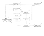
図1のブロック図は、本発明の測定装置の第1の実施形態の全体構成を示す。図1に示す様に、この測定装置は探触子4を備え、探触子4は、音響波を受信して受信信号(電気信号)に変換する電気機械変換装置である超音波トランスデューサを有し、乳房などの生体等の測定対象1に、形状維持部材である平板2を介して当接して使用される。探触子4には、探触子可動手段5、送信回路7及び受信回路8が接続されている。受信回路8には記憶部10が接続され、受信回路8と記憶部10には検知部11が接続され、探触子可動手段5と検知部11には探触子制御部6が接続され、送信回路7と受信回路8と検知部11には信号制御部9が接続されている。また、記憶部10と検知部11には画像処理部12が接続され、画像処理部12には画像表示手段13が接続されている。画像処理部12と画像表示手段13、或いは画像表示手段13は、測定装置とは別体となっていて、必要に応じて測定装置に着脱可能に接続される構成であってもよい。
Embodiments of the present invention will be described below with reference to the drawings.
(First embodiment)
The block diagram of FIG. 1 shows the overall configuration of the first embodiment of the measuring apparatus of the present invention. As shown in FIG. 1, this measuring apparatus includes a probe 4, and the probe 4 has an ultrasonic transducer that is an electromechanical transducer that receives an acoustic wave and converts it into a received signal (electric signal). In addition, it is used in contact with a
測定装置の測定動作時には、探触子4を測定対象1に当接させた状態において、信号制御部9により制御される送信回路7から探触子4へ超音波発信用の信号を供給する。探触子4と測定対象1との間には形状維持部材である平板2が配置され、軽圧迫により測定対象1の固定化ないし形状維持が行われている。また、音響整合剤3により測定対象1と探触子4との隙間を埋めてもよい。探触子4は、探触子可動手段5により平板2の表面上で移動させられ、走査が行われる。探触子4から送信された超音波は、測定対象1の生体組織などで反射され、探触子4により受信され受信信号に変換される。探触子から出力される受信信号は信号の増幅やA/D変換を行う受信回路8に入力された後、記憶部10に格納される。
During the measurement operation of the measuring device, a signal for transmitting an ultrasonic wave is supplied from the
ここで、受信時間tを、生体などの測定対象1が存在しない領域における走査距離xと探触子4の走査速度vからt=x/vと定義する。このとき、振幅がほぼ同じ受信信号の受信時間tが一定時間継続した場合、判定手段である検知部11により、生体などの測定対象1の存在しない領域を一定時間継続して探触子4が走査していることを検知する。生体などの測定対象1が存在しない領域の判定基準は、例えば、乳房を平板2により固定し、平板2上から探触子4を走査することにより乳癌の検出を行う場合を考えると、例えば、次の様にする。振幅がほぼ同じ受信信号の受信時間が一定時間継続して、それに対応する走査長が所定以上(例えば、平板2の長さの3倍以上)となった場合(走査は、後述する様に平板2上で折り返し行われるとする)、生体が存在しない領域の走査と判定する。この判定結果に基づき、次の様な動作制御を行うことができる。例えば、探触子制御部6による探触子走査の停止、信号制御部9による信号送受信の停止、画像処理部12による画像化処理領域の決定と記憶部10に格納された受信信号を用いた画像データの生成、画像表示手段13による画像表示を行う。この動作制御により、記憶部10に格納された受信信号に基づく画像が表示されるべきと判定されて必要な走査が終了され、診断時間を短縮することができる。或いは、上記判定結果に基づき、例えば、探触子走査の方向変更と速度変更を実行することもできる。この場合、走査方向変更を行なって走査位置を垂直方向に少しずらした後に再び水平方向逆方向に比較的高速で走査し、測定対象1の存在する領域に達したと判断される所で走査速度を通常速度に戻して走査を続ける。これによっても診断時間を短縮することができる。この場合は、上記一定時間は比較的短い時間とするのが良い。
Here, the reception time t is defined as t = x / v from the scanning distance x and the scanning speed v of the probe 4 in a region where the
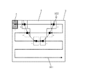
本実施形態の動作制御の例を図2の平面図で説明すると次の様になる。図2中の走査線101は、探触子4中の電気機械変換装置の中心の走査軌跡を示しており、実線は測定対象1がある領域の走査、破線は測定対象1がない領域の走査を示している。102は、測定対象1の有無を判定する為に注目する電気機械変換装置のエレメント群(各エレメントは1つ以上のセルを有する)である。注目エレメント群102は、探触子4中央に位置する複数のエレメントから構成され、注目エレメント群102の受信信号は、例えば、振幅がほぼ同じである状態が一定時間継続するか否かの判定の為に使用する。走査位置Aは、走査の原点で、この位置から探触子4の走査が開始される。走査位置Aでは測定対象1がない(注目エレメント群102が測定対象1を認識しない)ため、受信信号の記録動作や信号処理(信号の増幅やA/D変換等)を省くともに走査速度を高速化する。水平走査を開始して走査位置AからBまでは、注目エレメント群102が測定対象1を認識しないため水平走査を継続する。走査位置Bは、注目エレメント群102が、測定対象1がない領域からある領域へ移った位置を示している。走査位置Bからは測定対象1がある領域に入るため、測定対象診断に有効な領域として、受信信号の記録動作や信号処理を実行して、画像の撮像に好ましい速度まで走査速度を低下させる。
An example of the operation control of this embodiment will be described with reference to the plan view of FIG. A
走査位置Cは、注目エレメント群102が、測定対象1がある領域からない領域へ移った位置を示している。走査位置Cからは測定対象1から外れるため、測定対象診断に有効でない領域として、受信信号の記録動作や信号処理を省くと同時に走査速度を高速化して、走査位置Aと同様の走査制御を行い、走査方向を垂直方向にずらした後に逆転させる。走査位置Dでは、注目エレメント群102が、測定対象1がない領域からある領域へ移るため、測定対象診断に有効な領域として走査位置Bと同様の撮像制御を行う。以後、各位置E、F、Gでの測定対象1の有無判定に基づいて走査制御を繰り返し、平板2上を走査する。以上の動作制御により、測定対象1の有無を判定して測定対象診断に寄与しない走査領域において少なくとも走査速度を高速化することで全体の診断時間を短縮できる。こうした動作制御は、上記判定とは別に、予め設定しておく。そこで、この動作制御例では、これに加えて、振幅がほぼ同じ受信信号の受信時間が一定時間(例えば、平板2の長さの3倍以上に相当する時間)継続した場合、生体が存在しない領域の走査が続いて走査を終了すべきと判定する。この判定結果に基づき、探触子制御部6による探触子走査の停止、信号制御部9による信号送受信の停止、画像処理部12による画像化処理領域の決定と記憶部10に格納された受信信号を用いて画像データの生成、画像表示手段13による画像表示を行う。これにより、全体の診断時間を更に短縮することができる。
A scanning position C indicates a position where the
(第2の実施形態)
図3を用いて本発明の測定装置の第2の実施形態を説明する。本実施形態は、光のパルス照射により測定対象内で発生した音響波を受信し、画像データを生成する光音響トモグラフィ技術を用いたPAT(Photoacoustic Tomography)装置に関する。
(Second Embodiment)
A second embodiment of the measuring apparatus of the present invention will be described with reference to FIG. The present embodiment relates to a PAT (Photoacoustic Tomography) apparatus using a photoacoustic tomography technique that receives an acoustic wave generated in a measurement object by pulse irradiation of light and generates image data.
本実施形態のPAT装置は、光源111、光学部品113、形状維持部材である圧迫プレート2、探触子4、処理部30を備える。処理部30で生成した画像データは表示装置13により表示する。処理部30は、信号処理部20(第1の実施形態の受信回路、記憶部、検知部などを含む部分)、画像処理部12を有する。光源111から発せられた光112はミラーやレンズ等の光学部品113により導かれ、生体などの測定対象1に照射される。測定対象1の内部を伝播した光のエネルギーの一部が血管などの光吸収体14(結果的に音響波の発生源となる)に吸収されると、その光吸収体14の熱膨張により音響波17(典型的には超音波)が発生する。その発生した音響波17は探触子4により受信され、その後の処理により画像データとして生成(画像再構成)される。光源111は、生体を構成する成分のうち特定の成分に吸収される特定の波長の光を照射することを目的とする。光源111と光学部品113は測定装置と一体に設けられていても良いし、分離して別体として設けられていても良い。光源としては大きな出力が得られるレーザが好ましいが、レーザの代わりに発光ダイオードなどを用いることも可能である。照射のタイミング、波形、強度などは信号処理部20または不図示の制御部によって制御される。光源111から発生した光は、測定対象1上を移動可能となる様に構成されていることが好ましい。光を測定対象1に照射する領域(測定対象1に照射される光)は、探触子4と同期して移動すると更に好ましい。
The PAT apparatus of this embodiment includes a
形状維持部材2は、測定対象1と探触子4との間に設けられ、測定対象1の少なくとも一部の形状を一定に保つ為に用いられ、保持や圧迫の機能を持たせても良く、平板プレート、圧迫プレート、平行平板などである。形状維持部材1の材料としては、効率良く音響波を受信する為に、測定対象1の音響インピーダンスと近いものを選ぶのが好ましい。測定対象が乳房などの場合、ポリメチルペンテンからなる形状維持部材を使うことが望ましい。形状維持部材1が平板の場合、形状維持部材の厚さは音響波の減衰などを考慮すると薄い方が好ましいが、その形状が変形しない程度に厚くすることが望ましい。形状維持部材1と測定対象1との間や形状維持部材1と探触子4との間の隙間は、空隙を無くす為に、形状維持部材と同程度の音響インピーダンスを持つ音響整合剤である音響ジェルや水などの液体で埋めることが好ましい。
The shape maintaining member 2 is provided between the
探触子4は、音響波を受信して電気信号に変換する1つ以上のエレメントを有し、圧電現象を用いた電気機械変換装置、光の共振を用いた電気機械変換装置、容量の変化を用いた電気機械変換装置などで構成される。音響波を受信して電気信号に変換できるものであればどの様な探触子4を用いてもよい。典型的には、複数のエレメントが2次元的に配置されたものがよい。この様な2次元配列エレメントを用いることで、同時に複数の場所で音響波を受信することができ、受信時間を短縮できると共に、測定対象1の振動などの影響を低減できる。本実施形態で形状維持部材や探触子などについて述べたことは、第1の実施形態のこれらのものに関しても言い得る。図3の処理部30で行われる信号処理は、第1の実施形態のものと同じである。表示装置13は画像処理部12から出力される画像データを画像として表示する装置であり、典型的には液晶ディスプレイなどが利用される。これも、第1の実施形態の画像表示手段と同じである。PAT装置に係る本実施形態においても、測定動作の制御は第1の実施形態と同様に行うことができる。
The probe 4 includes one or more elements that receive an acoustic wave and convert it into an electrical signal. The probe 4 uses an electromechanical transducer that uses a piezoelectric phenomenon, an electromechanical transducer that uses light resonance, and changes in capacitance. It consists of an electromechanical conversion device using Any probe 4 may be used as long as it can receive acoustic waves and convert them into electrical signals. Typically, a plurality of elements arranged in a two-dimensional manner is preferable. By using such a two-dimensional array element, acoustic waves can be received simultaneously at a plurality of locations, the reception time can be shortened, and the influence of vibration of the measuring
本実施形態のPAT装置でも、測定対象1の有無を判定して測定対象診断に寄与しない走査領域において探触子の走査速度を高速化したり、適切なところで走査を終了させたりすることにより全体の診断時間を短縮することができる。
Even in the PAT apparatus according to the present embodiment, the entire scanning speed can be increased by determining the presence or absence of the measuring
(第3の実施形態)
第3の実施形態では、図1や図3に示す測定装置において、生体などの測定対象が存在しない領域における受信信号を参照信号として記憶部に予め格納しておく。参照信号としては、例えば、空気のみが存在した場合における空気に由来する受信信号、音響整合剤のみが存在した場合における音響整合剤に由来する受信信号を格納する。
(Third embodiment)
In the third embodiment, in the measurement apparatus shown in FIGS. 1 and 3, a reception signal in a region where a measurement target such as a living body does not exist is stored in advance in a storage unit as a reference signal. As the reference signal, for example, a reception signal derived from air when only air is present, and a reception signal derived from the acoustic matching agent when only the acoustic matching agent is present are stored.
測定装置の測定動作は第1や第2の実施形態と同様に行われる。このとき、記憶部に格納した参照信号と受信回路で受信した受信信号が所定時間ほぼ一致した場合、探触子4が測定対象1の存在しない領域を走査していることを検知部により判定する。測定対象が存在しない領域の判定基準は、乳房を平板により固定し平板上から探触子を走査することにより乳癌の検出を行う様な場合も、同様である。すなわち、参照信号とほぼ同じ受信信号の受信が所定時間続いた場合(例えば、該所定時間に相当する走査長が平板長さの3倍以上となった場合)、生体が存在しない領域の走査と判定する。そして、この判定結果に基づき、第1や第2の実施形態と同様な測定動作の制御を行う。
The measurement operation of the measurement apparatus is performed in the same manner as in the first and second embodiments. At this time, when the reference signal stored in the storage unit and the received signal received by the receiving circuit substantially coincide with each other for a predetermined time, the detection unit determines that the probe 4 is scanning an area where the
本発明は、乳癌のスクリーニング診断の様に、被験者数が多く、被験者により被験領域が異なる場合などにおける検査時間の短縮手段として有用である。 The present invention is useful as means for shortening the examination time when there are a large number of subjects and the test areas differ depending on the subjects, such as screening diagnosis of breast cancer.
1…生体(測定対象)、2…平板(形状維持部材)、4…探触子、10…記憶部、11…検知部(判定手段)
DESCRIPTION OF
Claims (9)
前記測定対象に対して計測光を出射するための照射手段と、
前記計測光が照射されることにより前記測定対象から発生する光音響波を前記形状維持部材を介して受信し受信信号に変換するための電気機械変換装置を有し、前記形状維持部材の表面に沿って走査される探触子と、
前記受信信号を格納するための記憶部と、
前記記憶部に格納された受信信号に基づき、前記探触子が前記測定対象の存在する前記形状維持部材の表面領域を走査しているかを判定するための判定手段と、
を有し、
前記判定手段は、前記受信信号の振幅が所定時間に亘ってほぼ変化していない場合に、前記探触子が前記測定対象の存在しない前記形状維持部材の表面領域を走査していると判定し、
前記判定手段による判定に基づき、当該測定装置の測定動作を制御することを特徴とする測定装置。 The shape maintaining member that holds the object to be measured,
Irradiating means for emitting measurement light to the measurement object;
Has an electromechanical converter for converting the photoacoustic wave generated from said object by carrying the measuring light is irradiated to the received signal received via the said shape maintaining member, the surface of the shape maintenance member A probe scanned along,
A storage unit for storing the received signal;
Based on the received signal stored in the storage unit, a determination unit for determining whether the probe is scanning the surface region of the shape maintaining member where the measurement target exists;
Have
The determination means determines that the probe is scanning the surface region of the shape maintaining member where the measurement target does not exist when the amplitude of the received signal has not changed substantially over a predetermined time. ,
A measuring apparatus that controls a measuring operation of the measuring apparatus based on the determination by the determining means.
前記電気機械変換装置の受信機能及び前記照射手段の計測光出射機能を制御するための信号制御部と、
前記探触子可動手段を制御するための探触子制御部と、
を有することを特徴とする請求項1または2に記載の測定装置。 A probe movable means for scanning the probe relative to the measurement object along a surface of said shape maintaining member,
A signal control unit for controlling the reception function of the electromechanical transducer and the measurement light emission function of the irradiation unit;
A probe controller for controlling the probe moving means;
The measuring apparatus according to claim 1, wherein:
前記探触子可動手段による前記探触子の走査の停止、前記探触子の走査速度変更、前記探触子の走査方向変更、前記信号制御部による前記電気機械変換装置の受信機能の停止、前記照射手段の計測光出射機能の停止のうちの少なくとも1つを行うことを特徴とする請求項4に記載の測定装置。 When the determination unit determines that the probe is scanning the surface region of the shape maintaining member where the measurement target does not exist,
Stop scanning of the probe by the probe moving means, the probe scanning speed changing of probe, the probe scanning direction changes probe, the receiving function before Symbol electromechanical transducer Ru good to the signal controller The measurement apparatus according to claim 4 , wherein at least one of stoppage of the measurement light and stop of the measurement light emission function of the irradiation unit is performed.
前記画像処理部による画像データの生成の開始に続く画像表示の開始を行うことを特徴とする請求項5に記載の測定装置。 When the determination unit determines that the probe is scanning the surface region of the shape maintaining member where the measurement target does not exist,
The measurement apparatus according to claim 5 , wherein an image display is started following the start of generation of image data by the image processing unit.
前記測定対象に対して計測光を出射する工程と、
前記計測光が照射されることにより前記測定対象から発生する光音響波を前記形状維持部材を介して受信し受信信号に変換するための電気機械変換装置を有する探触子を前記形状維持部材の表面に沿って走査する工程と、
前記受信信号を格納する工程と、
前記格納された受信信号に基づき、前記探触子が前記測定対象の存在する前記形状維持部材の表面領域を走査しているかを判定する工程と、
前記判定に基づき、当該測定方法の測定態様を制御する工程と、
を有し、
前記判定工程では、前記受信信号の振幅が所定時間に亘ってほぼ変化していない場合に、前記探触子が前記測定対象の存在しない前記形状維持部材の表面領域を走査していると判定することを特徴とする測定方法。 A measurement method for measuring a measurement object held by a shape maintaining member,
Emitting measurement light to the measurement object;
A probe having an electromechanical transducer for receiving a photoacoustic wave generated from the measurement object by being irradiated with the measurement light through the shape maintaining member and converting the photoacoustic wave into a received signal is provided on the shape maintaining member. Scanning along the surface;
Storing the received signal;
Determining whether the probe is scanning a surface area of the shape maintaining member on which the measurement object exists based on the stored received signal;
A step of controlling the measurement mode of the measurement method based on the determination;
I have a,
In the determination step, when the amplitude of the received signal has not changed substantially over a predetermined time, it is determined that the probe is scanning the surface region of the shape maintaining member where the measurement target does not exist. A measuring method characterized by the above.
前記探触子の走査の停止、前記探触子の走査速度変更、前記探触子の走査方向変更、前記電気機械変換装置の受信機能の停止、前記計測光の出射の停止のうちの少なくとも1つを行うことを特徴とする請求項8に記載の測定方法。At least one of stopping the scanning of the probe, changing the scanning speed of the probe, changing the scanning direction of the probe, stopping the reception function of the electromechanical transducer, and stopping the emission of the measurement light The measuring method according to claim 8, wherein the measuring method is performed.
Priority Applications (1)
| Application Number | Priority Date | Filing Date | Title |
|---|---|---|---|
| JP2010167728A JP5572023B2 (en) | 2010-07-27 | 2010-07-27 | measuring device |
Applications Claiming Priority (1)
| Application Number | Priority Date | Filing Date | Title |
|---|---|---|---|
| JP2010167728A JP5572023B2 (en) | 2010-07-27 | 2010-07-27 | measuring device |
Related Child Applications (1)
| Application Number | Title | Priority Date | Filing Date |
|---|---|---|---|
| JP2014133518A Division JP5868458B2 (en) | 2014-06-30 | 2014-06-30 | measuring device |
Publications (3)
| Publication Number | Publication Date |
|---|---|
| JP2012024426A JP2012024426A (en) | 2012-02-09 |
| JP2012024426A5 JP2012024426A5 (en) | 2013-09-12 |
| JP5572023B2 true JP5572023B2 (en) | 2014-08-13 |
Family
ID=45778104
Family Applications (1)
| Application Number | Title | Priority Date | Filing Date |
|---|---|---|---|
| JP2010167728A Expired - Fee Related JP5572023B2 (en) | 2010-07-27 | 2010-07-27 | measuring device |
Country Status (1)
| Country | Link |
|---|---|
| JP (1) | JP5572023B2 (en) |
Cited By (1)
| Publication number | Priority date | Publication date | Assignee | Title |
|---|---|---|---|---|
| JP2014176754A (en) * | 2014-06-30 | 2014-09-25 | Canon Inc | Measuring apparatus |
Families Citing this family (4)
| Publication number | Priority date | Publication date | Assignee | Title |
|---|---|---|---|---|
| JP6000591B2 (en) * | 2012-03-22 | 2016-09-28 | キヤノン株式会社 | Subject information acquisition apparatus and control method thereof |
| JP6271846B2 (en) * | 2013-03-14 | 2018-01-31 | キヤノン株式会社 | Device, bubble detection device, and bubble detection method |
| JP6645693B2 (en) * | 2015-10-05 | 2020-02-14 | キヤノン株式会社 | Subject information acquisition device and control method therefor |
| JP2016195940A (en) * | 2016-09-01 | 2016-11-24 | キヤノン株式会社 | Subject information acquisition device and control method thereof |
Family Cites Families (4)
| Publication number | Priority date | Publication date | Assignee | Title |
|---|---|---|---|---|
| JP2004290249A (en) * | 2003-03-25 | 2004-10-21 | Fuji Photo Film Co Ltd | Ultrasonic imaging apparatus and ultrasonic imaging method |
| JP2009082449A (en) * | 2007-09-28 | 2009-04-23 | Fujifilm Corp | Medical imaging apparatus |
| JP2009247730A (en) * | 2008-04-09 | 2009-10-29 | Toshiba Corp | Ultrasonic diagnosing device and ultrasonic image generation method |
| JP5159803B2 (en) * | 2008-06-18 | 2013-03-13 | キヤノン株式会社 | Subject information acquisition device |
-
2010
- 2010-07-27 JP JP2010167728A patent/JP5572023B2/en not_active Expired - Fee Related
Cited By (1)
| Publication number | Priority date | Publication date | Assignee | Title |
|---|---|---|---|---|
| JP2014176754A (en) * | 2014-06-30 | 2014-09-25 | Canon Inc | Measuring apparatus |
Also Published As
| Publication number | Publication date |
|---|---|
| JP2012024426A (en) | 2012-02-09 |
Similar Documents
| Publication | Publication Date | Title |
|---|---|---|
| JP5896623B2 (en) | Subject information acquisition apparatus and control method thereof | |
| US8997571B2 (en) | Ultrasonic probe, and photoacoustic-ultrasonic system and inspection object imaging apparatus including the ultrasonic probe | |
| JP4422626B2 (en) | Biological imaging device | |
| JP5393552B2 (en) | measuring device | |
| JP2009066110A (en) | Measurement apparatus | |
| JP2009068977A (en) | Measurement apparatus | |
| JP2011120796A (en) | Photoacoustic apparatus and method for controlling the same | |
| JP5572023B2 (en) | measuring device | |
| WO2013161289A1 (en) | Acoustic wave diagnosis device and image display method | |
| US20170049331A1 (en) | Object information acquiring apparatus and method of controlling the same | |
| JP2017042643A (en) | Subject information acquisition apparatus and subject information acquisition method | |
| JP5864904B2 (en) | Biological information acquisition device | |
| US20170325692A1 (en) | Acoustic wave receiving apparatus | |
| JP6742745B2 (en) | Information acquisition device and display method | |
| WO2013069450A1 (en) | Diagnostic ultrasound apparatus and ultrasound image-generating method | |
| US20150320321A1 (en) | Object information acquiring apparatus | |
| JP5868458B2 (en) | measuring device | |
| US20170319077A1 (en) | Sample information acquisition apparatus | |
| US20130345557A1 (en) | Light scanning probe and medical imaging apparatus employing the same | |
| JP5925267B2 (en) | measuring device | |
| JP5619254B2 (en) | measuring device | |
| JP2017202313A (en) | Acoustic wave reception device | |
| US20150119681A1 (en) | Method and apparatus for scanning excitation light for a photoacoustic image | |
| US20150374239A1 (en) | Object information acquiring apparatus and control method of object information acquiring apparatus | |
| JP6362123B2 (en) | apparatus |
Legal Events
| Date | Code | Title | Description |
|---|---|---|---|
| A521 | Request for written amendment filed |
Free format text: JAPANESE INTERMEDIATE CODE: A523 Effective date: 20130727 |
|
| A621 | Written request for application examination |
Free format text: JAPANESE INTERMEDIATE CODE: A621 Effective date: 20130727 |
|
| A131 | Notification of reasons for refusal |
Free format text: JAPANESE INTERMEDIATE CODE: A131 Effective date: 20140107 |
|
| A977 | Report on retrieval |
Free format text: JAPANESE INTERMEDIATE CODE: A971007 Effective date: 20140110 |
|
| A521 | Request for written amendment filed |
Free format text: JAPANESE INTERMEDIATE CODE: A523 Effective date: 20140310 |
|
| TRDD | Decision of grant or rejection written | ||
| A01 | Written decision to grant a patent or to grant a registration (utility model) |
Free format text: JAPANESE INTERMEDIATE CODE: A01 Effective date: 20140530 |
|
| A61 | First payment of annual fees (during grant procedure) |
Free format text: JAPANESE INTERMEDIATE CODE: A61 Effective date: 20140627 |
|
| R151 | Written notification of patent or utility model registration |
Ref document number: 5572023 Country of ref document: JP Free format text: JAPANESE INTERMEDIATE CODE: R151 |
|
| RD03 | Notification of appointment of power of attorney |
Free format text: JAPANESE INTERMEDIATE CODE: R3D03 |
|
| LAPS | Cancellation because of no payment of annual fees |