JP5570552B2 - Delivery prediction system and delivery prediction method - Google Patents
Delivery prediction system and delivery prediction method Download PDFInfo
- Publication number
- JP5570552B2 JP5570552B2 JP2012130613A JP2012130613A JP5570552B2 JP 5570552 B2 JP5570552 B2 JP 5570552B2 JP 2012130613 A JP2012130613 A JP 2012130613A JP 2012130613 A JP2012130613 A JP 2012130613A JP 5570552 B2 JP5570552 B2 JP 5570552B2
- Authority
- JP
- Japan
- Prior art keywords
- gas
- amount
- date
- guideline
- delivery
- Prior art date
- Legal status (The legal status is an assumption and is not a legal conclusion. Google has not performed a legal analysis and makes no representation as to the accuracy of the status listed.)
- Active
Links
- 238000000034 method Methods 0.000 title claims description 14
- 230000008859 change Effects 0.000 claims description 46
- 238000007726 management method Methods 0.000 claims description 12
- 238000004891 communication Methods 0.000 claims description 6
- 230000003247 decreasing effect Effects 0.000 claims 2
- 238000003860 storage Methods 0.000 description 28
- 238000010586 diagram Methods 0.000 description 9
- 230000008569 process Effects 0.000 description 5
- 238000001816 cooling Methods 0.000 description 3
- 238000009826 distribution Methods 0.000 description 3
- 238000010438 heat treatment Methods 0.000 description 3
- 230000004048 modification Effects 0.000 description 3
- 238000012986 modification Methods 0.000 description 3
- 238000012545 processing Methods 0.000 description 3
- 230000008676 import Effects 0.000 description 2
- 238000009434 installation Methods 0.000 description 2
- 238000004519 manufacturing process Methods 0.000 description 2
- 230000009467 reduction Effects 0.000 description 2
- 230000006399 behavior Effects 0.000 description 1
- 238000004364 calculation method Methods 0.000 description 1
- 238000012790 confirmation Methods 0.000 description 1
- 238000013500 data storage Methods 0.000 description 1
- 230000006870 function Effects 0.000 description 1
- 238000007689 inspection Methods 0.000 description 1
- 230000007246 mechanism Effects 0.000 description 1
- 239000003208 petroleum Substances 0.000 description 1
- 239000003209 petroleum derivative Substances 0.000 description 1
- 238000007670 refining Methods 0.000 description 1
- 230000004044 response Effects 0.000 description 1
- 238000012546 transfer Methods 0.000 description 1
Images


Classifications
-
- G—PHYSICS
- G06—COMPUTING; CALCULATING OR COUNTING
- G06Q—INFORMATION AND COMMUNICATION TECHNOLOGY [ICT] SPECIALLY ADAPTED FOR ADMINISTRATIVE, COMMERCIAL, FINANCIAL, MANAGERIAL OR SUPERVISORY PURPOSES; SYSTEMS OR METHODS SPECIALLY ADAPTED FOR ADMINISTRATIVE, COMMERCIAL, FINANCIAL, MANAGERIAL OR SUPERVISORY PURPOSES, NOT OTHERWISE PROVIDED FOR
- G06Q10/00—Administration; Management
- G06Q10/06—Resources, workflows, human or project management; Enterprise or organisation planning; Enterprise or organisation modelling
- G06Q10/063—Operations research, analysis or management
- G06Q10/0631—Resource planning, allocation, distributing or scheduling for enterprises or organisations
- G06Q10/06315—Needs-based resource requirements planning or analysis
-
- G—PHYSICS
- G01—MEASURING; TESTING
- G01F—MEASURING VOLUME, VOLUME FLOW, MASS FLOW OR LIQUID LEVEL; METERING BY VOLUME
- G01F23/00—Indicating or measuring liquid level or level of fluent solid material, e.g. indicating in terms of volume or indicating by means of an alarm
-
- G—PHYSICS
- G06—COMPUTING; CALCULATING OR COUNTING
- G06Q—INFORMATION AND COMMUNICATION TECHNOLOGY [ICT] SPECIALLY ADAPTED FOR ADMINISTRATIVE, COMMERCIAL, FINANCIAL, MANAGERIAL OR SUPERVISORY PURPOSES; SYSTEMS OR METHODS SPECIALLY ADAPTED FOR ADMINISTRATIVE, COMMERCIAL, FINANCIAL, MANAGERIAL OR SUPERVISORY PURPOSES, NOT OTHERWISE PROVIDED FOR
- G06Q10/00—Administration; Management
- G06Q10/08—Logistics, e.g. warehousing, loading or distribution; Inventory or stock management
-
- G—PHYSICS
- G06—COMPUTING; CALCULATING OR COUNTING
- G06Q—INFORMATION AND COMMUNICATION TECHNOLOGY [ICT] SPECIALLY ADAPTED FOR ADMINISTRATIVE, COMMERCIAL, FINANCIAL, MANAGERIAL OR SUPERVISORY PURPOSES; SYSTEMS OR METHODS SPECIALLY ADAPTED FOR ADMINISTRATIVE, COMMERCIAL, FINANCIAL, MANAGERIAL OR SUPERVISORY PURPOSES, NOT OTHERWISE PROVIDED FOR
- G06Q50/00—Systems or methods specially adapted for specific business sectors, e.g. utilities or tourism
- G06Q50/06—Electricity, gas or water supply
Description
本発明は、供給設備に備えられる液化石油(LP)ガスのガス容器の配送日を予測するシステムおよび方法に関する。 The present invention relates to a system and method for predicting the delivery date of a gas container of liquefied petroleum (LP) gas provided in a supply facility.
LPガスは、産ガス国からの輸入と、石油製品の生産過程で副生される国内生産とにより供給されていることが知られている。産ガス国からタンカーで運ばれてきたLPガスを保管する輸入基地、および石油精製基地をそれぞれ一次基地と呼び、LPガスは、一次基地から内航船やタンクローリーに積み込まれて、沿岸または内陸にあるLPガス輸送時の中継基地である二次基地へと出荷される。さらに、二次基地に運ばれてきたLPガスは、各地にあるLPガス充填所、すなわち配送拠点に輸送されて、配送拠点においてガス容器(ガスボンベ)に充填される。 It is known that LP gas is supplied by imports from gas producing countries and domestic production by-produced in the production process of petroleum products. The import base that stores LP gas transported by tankers from oil-producing countries and the oil refining base are called primary bases, and LP gas is loaded into coastal ships and tank trucks from the primary base and is on the coast or inland. Shipped to a secondary base that is a transit base for LP gas transport. Furthermore, the LP gas that has been transported to the secondary base is transported to LP gas filling stations in various places, that is, delivery bases, and filled in gas containers (gas cylinders) at the delivery bases.
各充填所において充填されたガス容器は、配送員によって、一般家庭、集合住宅、事業所などの顧客宅に配送される。顧客宅の空になったガス容器が、充填されたガス容器と交換され、空になったガス容器は、充填所に回収される。各充填所においては、配送員が担当する固定的な配送エリアが設定されている。配送員には、配送エリア内の顧客宅に配送すべき、2〜10日分の配送伝票が渡される。 The gas container filled in each filling station is delivered by a delivery member to a customer's home such as a general household, a housing complex, and a business office. The empty gas container at the customer's house is replaced with the filled gas container, and the empty gas container is collected at the filling station. In each filling station, a fixed delivery area is set for the delivery person. The delivery person is given a delivery slip for 2 to 10 days to be delivered to the customer's home in the delivery area.
配送伝票は、配送管理者によって作成される。最初に、顧客ごとに過去のガス使用量の実績、顧客宅のガスメータのメータ指針、配送実績等を基に、ガス容器内のLPガスの残量を予測して、次回のガス容器の配送予定日が決定される。配送員が担当する配送エリア内の顧客の全てについて積算し、2〜10日分のガス容器の配送量が決定される。 The delivery slip is created by the delivery manager. First, based on the past gas usage results for each customer, the meter guidelines of the gas meter at the customer's house, delivery results, etc., the remaining amount of LP gas in the gas container is predicted, and the next gas container delivery plan The day is determined. The total of all the customers in the delivery area handled by the delivery person is accumulated, and the delivery amount of the gas container for 2 to 10 days is determined.
配送員は、配送伝票に従ってガス容器を交換すると、交換した日付、当日のメータ指針、容器番号、保安検査の各項目を配送伝票に記入する。配送伝票は、日々の配送作業が終了すると、配送管理者に提出される。配送管理者に返却された配送伝票は、配送管理者によって記入漏れがないかチェックされた後、次回の配送予定日を算出するためのデータとして保管される。このような仕組みの下で、ガス容器の配送を効率化するためのシステムが提案されている(特許文献1参照)。 When the delivery person replaces the gas container according to the delivery slip, the delivery date, the meter pointer on the day, the container number, and the security check are entered in the delivery slip. The delivery slip is submitted to the delivery manager when the daily delivery work is completed. The delivery slip returned to the delivery manager is stored as data for calculating the next scheduled delivery date after being checked by the delivery manager for omissions. Under such a mechanism, a system for improving the efficiency of delivery of gas containers has been proposed (see Patent Document 1).
特許文献1に開示されているように、ガス容器の配送の効率化を図るシステムは従来から存在したものの、ガス供給の安定供給を可能とし、さらには、持ち帰りガス残量の低減を可能とするガス容器の配送日の予測をすることができない問題があった。
As disclosed in
そこで本発明の目的は、このような状況に鑑み、ガス供給の安定供給を可能とし、さらには、持ち帰りガス残量の低減を可能とするガス容器の配送日の予測を行うことができる配送予測システムおよび配送予測方法を提供することにある。 Accordingly, an object of the present invention is to provide a delivery prediction capable of stably supplying a gas supply and predicting a delivery date of a gas container that can reduce the amount of the take-out gas remaining in view of such a situation. To provide a system and a delivery prediction method.
上記課題を解決するために、本発明は、複数の供給設備に備えられるガス容器の配送予測を行う配送予測システムであって、前記供給設備におけるガス容器別のガス残量と、前記各供給設備のエリアとを管理する管理部と、通信端末から、前記ガス容器のガス使用量を検出するガスメータの指針データを受け付ける受付部と、前記受け付けられた今回の指針データと前回の指針データとの比較に基づいて、前回の指針日から今回の指針日までの間に前記供給設備において使用されたガス使用量を算出し、前記ガス使用量に基づいて、対応するガス容器のガス残量を前記管理部で更新する更新部と、前記算出されたガス使用量に基づいて得られる前回の指針日から今回の指針日までの間に使用された一日当たりのガス使用量と、予め定められた過去の期間における前記供給設備についての指針データに基づいて得られる過去の一日当たりのガス使用量の第1の変化率を算出するとともに、前記管理部の同一エリアに備えられる前記各供給設備についての前記指針データの比較に基づいて、前記同一のエリア内における過去の一日当たりのガス使用量の第2の変化率を算出し、前記供給設備についての前記第1の変化率と、前記供給設備が備えられるエリアと同一のエリア内における前記第2の変化率とに基づいて、当該供給設備に備えられたガス容器に対する将来の一日当たりのガス使用量を予測し、将来の一日当たりのガス使用量に応じて、前記更新されたガス残量を減少させて将来のガス残量を予測する予測部と、前記予測されたガス残量が所定値となる日を、前記供給設備におけるガス容器の配送日として決定する決定部とを含むものである。 In order to solve the above-mentioned problems, the present invention is a delivery prediction system for predicting delivery of gas containers provided in a plurality of supply facilities , wherein the remaining amount of gas for each gas container in the supply facilities and each of the supply facilities A management unit that manages the area of the gas container, a reception unit that receives the gas meter guide data for detecting the gas usage of the gas container from the communication terminal, and a comparison between the received current guide data and the previous guide data Based on the above, the amount of gas used in the supply facility between the previous guideline date and the current guideline date is calculated, and the remaining gas amount in the corresponding gas container is managed based on the gas use amount. A renewal unit to be renewed by the unit, a gas use amount per day used between the previous guideline date and the current guideline date obtained based on the calculated gas use amount, and a predetermined amount Calculates the first change rate per day of gas consumption in the past obtained based on the guidance data for said supply facility for the period to, the for each supply system provided in the same area of the management unit Based on the comparison of the guideline data, a second rate of change of gas usage per day in the same area is calculated, and the first rate of change for the supply facility and the supply facility are calculated. Based on the second rate of change in the same area as the area provided, the future daily gas usage for the gas container provided in the supply facility is predicted, and the future daily gas usage In response, a prediction unit for reducing the updated gas remaining amount to predict a future gas remaining amount, and a date when the predicted gas remaining amount becomes a predetermined value are provided to the supply facility. That is intended to include a determiner that determines a delivery date of the gas container.
また、上記課題を解決するために、本発明は、コンピューターが、複数の供給設備に備えられるガス容器の配送予測を行う配送予測方法であって、前記コンピューターは、前記供給設備におけるガス容器別のガス残量と、前記各供給設備のエリアとを管理する管理部を備えており、通信端末から、前記ガス容器のガス使用量を検出するガスメータの指針データを受け付けるステップと、前記受け付けられた今回の指針データと前回の指針データとの比較に基づいて、前回の指針日から今回の指針日までの間に前記供給設備において使用されたガス使用量を算出し、前記ガス使用量に基づいて、対応するガス容器のガス残量を前記管理部で更新するステップと、前記算出されたガス使用量に基づいて得られる前回の指針日から今回の指針日までの間に使用された一日当たりのガス使用量と、予め定められた過去の期間における前記供給設備についての指針データに基づいて得られる過去の一日当たりのガス使用量の第1の変化率を算出するとともに、前記管理部の同一エリアに備えられる前記各供給設備についての前記指針データの比較に基づいて、前記同一のエリア内における過去の一日当たりのガス使用量の第2の変化率を算出し、前記供給設備についての前記第1の変化率と、前記供給設備が備えられるエリアと同一のエリア内における前記第2の変化率とに基づいて、当該供給設備に備えられたガス容器に対する将来の一日当たりのガス使用量を予測し、将来の一日当たりのガス使用量に応じて、前記更新されたガス残量を減少させて将来のガス残量を予測するステップと、前記予測されたガス残量が所定値となる日を、前記供給設備におけるガス容器の配送日として決定するステップとを含むものである。 In order to solve the above-mentioned problem, the present invention provides a delivery prediction method in which a computer predicts delivery of gas containers provided in a plurality of supply facilities, and the computer is provided for each gas container in the supply facility. A management unit for managing the remaining amount of gas and the area of each of the supply facilities, and receiving from the communication terminal the pointer data of the gas meter for detecting the amount of gas used in the gas container; Based on the comparison between the guideline data and the previous guideline data, the amount of gas used in the supply facility between the previous guideline date and the current guideline date is calculated, and based on the gas use amount, From the previous guide date to the current guide date obtained based on the step of updating the remaining gas amount of the corresponding gas container by the management unit and the calculated gas usage amount Calculates the daily gas consumption used during the first change rate per day of gas consumption in the past obtained based on the guidance data for said supply facility in a period of the past predetermined And calculating a second rate of change of gas consumption per day in the same area based on a comparison of the guideline data for the supply facilities provided in the same area of the management unit, Based on the first rate of change of the supply facility and the second rate of change in the same area as the area where the supply facility is provided, a future one for the gas container provided in the supply facility is determined. Predicting gas usage per day, and predicting future gas residuals by reducing the updated gas residuals according to future daily gas usages; The date serial predicted residual gas quantity becomes a predetermined value, is intended to include determining the delivery date of the gas container in the supply system.
本発明によれば、ガス供給の安定供給を可能とし、さらには、持ち帰りガス残量の低減を可能とするガス容器の配送日の予測を行うことができる。 According to the present invention, it is possible to predict the delivery date of a gas container that enables stable supply of gas supply, and further enables reduction of the remaining amount of take-out gas.
以下、本実施形態におけるシステムの概要構成を説明する。このシステムは、ガスメータのメータ指針を含む指針データを利用して、供給設備に備えられたガス容器の配送日の予測を行うものである。 Hereinafter, a schematic configuration of the system in the present embodiment will be described. This system predicts the delivery date of a gas container provided in a supply facility using guide data including a meter guide of a gas meter.
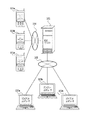
図1は本発明の一実施形態に係るネットワーク構成を示す図である。図1において、配送サーバー(配送予測システム)101は、ネットワーク102を介して、複数のクライアントコンピューター103a、103b、・・・、103nと通信可能に構成されている。さらに、この配送サーバー101は、ネットワーク104を介して、複数のモバイル端末(通信端末)105a、105b、・・・、105nと通信可能に構成されている。なお、複数のクライアントコンピューター103a〜103nの各々に共通の説明では各クライアントコンピューターが単にクライアントコンピューター103として参照され、複数のモバイル端末105a〜105nの各々に共通の説明では各モバイル端末が単にモバイル端末105として参照される。
FIG. 1 is a diagram showing a network configuration according to an embodiment of the present invention. In FIG. 1, a delivery server (delivery prediction system) 101 is configured to be able to communicate with a plurality of
クライアントコンピューター103は、例えば各配送拠点の配送を一元で管理する配送センターに設置され、配送センターのユーザーによって使用される端末である。ユーザーは、クライアントコンピューター103を介して配送サーバー101に接続し、配送状況の確認、配送データの作成指示など、配送業務を専用で行う。なお、クライアントコンピューター103の設置場所は、例えば配送拠点などとしてもよい。
For example, the
モバイル端末105は、ガス容器を備える供給設備に取り付けられたガスメータを指針する作業員(例えば配送員、保安員なども含む。)によって使用される端末であり、CPU、メモリ、入力装置および表示装置などを備える。モバイル端末は、例えば携帯電話機、携帯情報端末等である。上記作業員は、モバイル端末105を介してガスメータのメータ指針を含む指針データを収集して、配送サーバー101へ送信する。なお、指針データが配送サーバー101に送信される場合として、例えば、ガスメータの検針時、ガスの開閉栓時、保安調査時、ガス容器の配送時などがある。
The mobile terminal 105 is a terminal used by a worker who points a gas meter attached to a supply facility including a gas container (including a delivery person, a security worker, etc.), and includes a CPU, a memory, an input device, and a display device. Etc. The mobile terminal is, for example, a mobile phone or a portable information terminal. The worker collects the guide data including the meter guide of the gas meter via the mobile terminal 105 and transmits it to the
[配送サーバーの構成]
図2は配送サーバー101の構成例を示すブロック図である。なお、図2では、単一のコンピュータシステムが採用される場合について説明するが、配送サーバー101が複数のコンピュータシステムによる多機能の分散システムの一部として構成されることもあり得る。
[Configuration of the delivery server]
FIG. 2 is a block diagram illustrating a configuration example of the
図2に示すように、配送サーバー101は、CPU301、システムバス302、RAM303、入力装置304、出力装置305、通信制御装置306および記憶装置(管理部)307を有する。
As illustrated in FIG. 2, the
CPU301は、各構成要素とシステムバス302で接続されて制御信号やデータの転送処理を行うとともに、配送サーバー101全体の動作を実現するための各種のソフトウェアプログラムの実行、演算処理等を行う。
The
RAM303には、データやソフトウェアプログラムを一時的に記憶するためのワークエリアが設けられている。
The
記憶装置307は、ROMやHDDなどの不揮発性記憶媒体で構成され、ソフトウェアプログラムを格納するプログラム格納領域と、随時取得するデータや処理結果としてのデータなどを格納するデータ格納領域とを備える。例えば記憶装置307のプログラム格納領域からソフトウェアプログラムがRAM303のワークエリアに読み出されてCPU301によって当該ソフトウェアプログラムが実行されることにより、この実施形態のCPU301は後述する各部31〜34の機能を実現する。なお、ソフトウェアプログラムは、DVD−ROMやCD−ROM等のコンピューター読み取り可能な情報記憶媒体に格納されてよい。
The
CPU301は、図2に示すように、受付部31、更新部32、予測部33および決定部34を備える。
As illustrated in FIG. 2, the
受付部31は、モバイル端末105から、供給設備に備えられるガス容器のガス使用量を検出するガスメータの指針データを受け付ける。この実施形態では、指針データは、ガス容器のガス残量を示すメータ指針および指針日等を含むが、詳細については後述する。
The accepting
更新部32は、受付部31によって受け付けられた今回の指針データと、前回の指針データとの比較に基づいて、前回の指針日から今回の指針日までの間に使用されたガス使用量を算出し、そのガス使用量に基づいて、記憶装置307に管理されている当該ガス容器のガス残量を更新する。この実施形態では、指針データは、ガス容器のガス使用量を示すメータ指針および指針日を含むので、更新部32は、例えば{(今回の指針日のメータ指針)−(前回の指針日のメータ指針)}から前回の指針日から今回の指針日までの間に使用されたガス使用量を求めて、同一のガス容器に対するガス残量を算出する。換言すれば、ガス残量を更新する処理は、上記受け付けられた指針データを含む複数の指針データの比較に基づいて得られるガス使用量に基づいて行われる。ガス残量を更新する処理については、後に詳細に説明する。
The updating
なお、この実施形態では、過去のガス使用量の変化率を算出する場合について説明するが、顧客が移転することなどから、状況次第では同一の顧客が過去にガスを使用した実績がないこともあり得る。この場合には、過去のガス使用量の変化率を算出することなく、どの程度ガスを使用するかについての情報(例えば、想定使用量)を、顧客との契約内容(利用状況、用途など)からあらかじめ設定しておけばよい。 In this embodiment, the case of calculating the rate of change in the past gas consumption will be described. However, depending on the situation, the same customer may not have used gas in the past because the customer has moved. possible. In this case, without calculating the rate of change in past gas usage, information on how much gas is used (eg, estimated usage) and the details of the contract with the customer (usage status, usage, etc.) Set in advance.
予測部33は、更新部32によって算出されたガス使用量に基づいて得られる前回の指針日から今回の指針日までの間に使用された一日当たりのガス使用量と、予め定められた過去の期間における前記供給設備についての指針データに基づいて得られる過去の一日当たりのガス使用量の変化率とに基づいて、当該供給設備に備えられたガス容器に対する将来の一日当たりのガス使用量を予測する。この実施形態では、過去の期間は、例えば、前年度の同時期の指針期間(指針当月から指針翌月まで)であるが、予測部33が将来のガス使用量の変化率を予測することが可能であれば、過去の一日当たりのガス使用量の変化率または予め定められた過去の期間として、他の形態もとり得る。
The
また、この実施形態の予測部33は、予測された将来の一日当たりのガス使用量に応じて、更新部32によって更新されたガス残量を減少させて将来のガス残量を予測する。次予測部33における予測の処理については、後に詳細に説明する。
Further, the
決定部33は、予測部32によって予測されたガス残量が所定値となる日を、供給設備におけるガス容器の配送日として決定する。この決定の処理については、後に詳細に説明する。
The
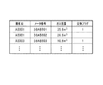
図3は配送サーバー101の記憶装置307に格納された顧客情報の構成例を示す図である。記憶装置307には、図3に示すように、顧客を識別するための「顧客ID」、およびガスメータを識別するための「メータ番号」等が格納される。さらに記憶装置307には、ガス容器の容量を示す「ガス容器容量」、供給設備に備えられるガス容器の本数を示す「本数」、2系列のガス容器群を全数交換するか否かを示す「全数半数区分」、および供給設備が設けられるエリアを識別するための「エリアコード」が格納される。図3の例では、「全数半数区分」には、全数の場合は「1」、半数の場合は「2」とする。全数を示す「1」の場合は2系列目のガス容器を交換するときに1系列目のガス容器も交換することを意味し、半数を示す「2」の場合は1本のガス容器ずつ交換することを意味する。
FIG. 3 is a diagram illustrating a configuration example of customer information stored in the
CPU301は、例えば全数交換の対象となるガス容器群のうち、1系列目のガス容器のガス残量を予測するときには、算出されたガス使用量に応じて、2系列目のガス容器のガス残量を予測する。この場合、ガス残量の予測は、安全率sに基づいて行われる。例えば、安全率sは、ガス容器の容量と前回の配送重量(実績使用量)とを考慮して設定される。例えば、安全率sが20%に予め設定され、前回配送時の第1系列および第2系列のガス容器の合計容量が400kgの場合、CPU301では、前回配送時の第1系列および第2系列の合計容量、すなわち使用可能な残量を、400kg×(100−s)/100)から320kgとして判定する。
For example, when predicting the remaining amount of gas in the first series of gas containers in the group of gas containers to be replaced, the
図4は配送サーバー101の記憶装置307に格納されたガス残量を含む情報の構成例を示す図である。記憶装置307には、図4に示すように、上述した「顧客ID」と、上述した「メータ番号」と、「ガス残量」と、「交換フラグ」とが格納される。「ガス残量」は、現在使用中のガス容器のガス残量を表している。「交換フラグ」は、現在使用中のガス容器のガス残量が所定値となる場合にガス容器を交換するか否かを示す情報である。例えば、半数交換の場合であれば供給設備が2本のガス容器を備えるときに、1本目のガス容器が空になると2本目のガス容器からガスを供給する場合がある(自動切替装置設置時)ので、ガス容器の配送の有無を判断するために交換フラグが必要となる。「交換フラグ」中の「1」は、交換対象のガス容器であることを意味する。
FIG. 4 is a diagram illustrating a configuration example of information including the remaining gas amount stored in the
[配送サーバーの動作]
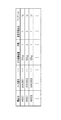
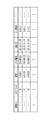
次に、モバイル端末105から、配送サーバー101に対してガスメータの指針データが送信された場合に、その指針データを利用して予測されたガス容器のガス残量に基づいて、ガス容器の配送日を決定する方法について図5〜9を参照して説明する。図5は配送サーバー101の全体動作例を示すフローチャートである。図6は指針データの一例を示す図である。図7は配信サーバー101の記憶装置307に格納された複数の指針データの構成例を示す図である。図8は前年度における顧客のガス使用量の実績を説明するための図である。図9はガスメータの検針後にガス容器の配送日を決定する概略を時系列に説明するための図である。
[Delivery server behavior]
Next, when the gas meter guide data is transmitted from the mobile terminal 105 to the
図5〜図9では、一例として、配送サーバー101が、検針時の指針データを受け付ける場合の例を表しているが、ガスの開閉栓時、保安調査時またはガス容器の配送時の指針データを受け付けるようにしてもよい。
FIGS. 5 to 9 show an example in which the
図5において先ず、モバイル端末105が配送サーバー101に対してガスメータの指針データを送信した場合、配送サーバー101のCPU301(受付部31)は、その指針データを受け付ける(S101)。ここで、モバイル端末105から送信される指針データの一例を図6に示す。
5, first, when the mobile terminal 105 transmits the gas meter guide data to the
図6に示すように、指針データは、検針の伝票ID、エリアコード、検針員ID、検針日、顧客ID、メータ番号、メータ指針等を含む。この実施形態では、ガスメータには、例えばQRコード(登録商標)(読み取り可能な情報コード)が付けられているために、モバイル端末105は、そのQRコード(登録商標)を読み込むことで、メータ指針および検針日を除く指針データを取得することができるようになっている。なお、メータ指針は、例えば検針員の入力操作に基づいて取得され、検針日は、例えばQRコード(登録商標)の読み込み日とされる。 As shown in FIG. 6, the pointer data includes a meter reading slip ID, an area code, a meter reader ID, a meter reading date, a customer ID, a meter number, a meter pointer, and the like. In this embodiment, since the QR meter (registered trademark) (readable information code) is attached to the gas meter, for example, the mobile terminal 105 reads the QR code (registered trademark), thereby In addition, it is possible to acquire guideline data excluding the meter reading date. The meter pointer is acquired based on, for example, an input operation by a meter reader, and the meter reading date is, for example, a QR code (registered trademark) reading date.
配送サーバー101は、指針データを受け付けると、その指針データを記憶装置307に記憶する。この記憶例を図7に示す。
Upon receiving the guideline data, the
図7に示すように、記憶装置307には、CPU301によって受け付けられた複数の指針データが記憶されている。
As shown in FIG. 7, the
図5のS102において、CPU301(更新部32)は、S101で受け付けられた今回の指針データと、前回の指針データとの比較に基づいて得られる前回の検針日から今回の検針日までの間に使用されたガス使用量A(m3)に基づいて、記憶装置307に管理されている当該ガス容器のガス残量を更新する。
In S102 of FIG. 5, the CPU 301 (update unit 32) performs a period between the previous meter reading date and the current meter reading date obtained based on the comparison between the current pointer data received in S101 and the previous pointer data. Based on the used gas usage A (m 3 ), the remaining amount of gas in the gas container managed by the
この場合、CPU301は、上記受け付けられた今回の指針データと前回の指針データとを記憶装置307から読み出し、2つの指針データのメータ指針の差分から、同一の供給設備において前回の検針日から今回の検針日までの間に使用されたガス使用量A(m3)を算出する。そして、CPU301は、そのガス使用量A(m3)を、記憶装置307に管理されている当該ガス容器のガス残量から減算して、記憶装置307の「ガス残量」を減算後の値に設定する。これにより、今回の検針時に残存していたガス容器のガス量が設定される。
In this case, the
なお、S102において、CPU301(更新部32)が供給側のガス容器のガス残量からガス使用量を減算した結果、供給側のガス容器のガス残量が「0」となり、かつ、記憶装置307の交換フラグが「1」でない場合は、供給設備に備えられている別のガス容器、すなわち予備側のガス容器のガス残量から残りのガス使用量を減算して、その予備側のガス容器のガス残量を更新する。例えば、予備側のガス容器のガス容量が50kgの場合は、CPU301は、供給側のガス容器から予備側のガス容器に食い込んで消費されるガス使用量を、予備側のガス容器のガス容量(50kg)から減算して予備側のガス容器のガス残量を求める。この実施形態では、交換フラグが「1」でないときには、全数交換の対象となるガス容器群のうちの1本目のガス容器が現在使用されていることを意味する。
In S102, as a result of the CPU 301 (update unit 32) subtracting the amount of gas used from the gas remaining amount in the supply-side gas container, the remaining gas amount in the supply-side gas container becomes “0”, and the
図5のS103において、CPU301(予測部33)は、S102で算出されたガス使用量A(m3)に基づいて得られる前回の検針日から今回の検針日までの間に使用された一日当たりのガス使用量N(m3/日)と、予め定められた過去の期間における供給設備についての指針データに基づいて得られる過去の一日当たりのガス使用量の変化率αとに基づいて、当該供給設備に備えられたガス容器に対する将来の一日当たりのガス使用量を予測する。この場合、CPU301は、一日当たりのガス使用量N(m3/日)を、例えば{ガス使用量A(m3)/(前回の検針日から今回の検針日までの日数)}の式から得る。
In S103 of FIG. 5, the CPU 301 (prediction unit 33) per day used between the previous meter reading date and the current meter reading date obtained based on the gas usage A (m 3 ) calculated in S102. Based on the gas usage amount N (m 3 / day) and the rate of change α of the past gas usage per day obtained based on the guideline data on the supply equipment in a predetermined past period, Estimate future gas usage per day for gas containers in the supply facility. In this case, the
この実施形態では、将来の一日当たりのガス使用量は、前年度の同時期比から求められるので、CPU301は、過去の一日当たりのガス使用量の変化率αを、{(今回の検針月の翌月における前年度の一日当たりのガス使用量)/(今回の検針月の同月における前年度の一日当たりのガス使用量)}の式から得る。
In this embodiment, since the gas usage per day in the future is obtained from the same period of the previous year, the
例えば、今回のガスメータの検針が2月の場合、過去の一日当たりのガス使用量の変化率αは、{(3月における前年度の一日当たりのガス使用量)/(2月における前年度の一日当たりのガス使用量)}の式から得られる。図8の例では、前年2月の1日当たりのガス使用量が4.2(m3/日)、前年3月の1日当たりのガス使用量が3.0(m3/日)として示されているから、CPU301によって算出されるガス使用量の変化率αは、α=3.0/4.2となる。なお、図8では、前年1月から前年2月の1日当たりのガス使用量の変化率αは、α=4.2/3.0として表してある。これにより、前年度の同時期における1日当たりのガス使用量の増減率αが求められる。
For example, if the meter reading of this gas meter is February, the rate of change α of gas usage per day in the past is {(gas usage per day in the previous year in March) / (the previous year in February). Gas consumption per day)}. In the example of FIG. 8, the gas usage per day in February of the previous year is 4.2 (m 3 / day), and the gas usage per day in March of the previous year is 3.0 (m 3 / day). Therefore, the change rate α of the gas usage calculated by the
なお、過去の一日当たりのガス使用量の変化率αは、前年度よりも前の同時期比(例えば、2年前)から求めるようにしてもよい。また、過去の一日当たりのガス使用量の変化率αは、数年度分(例えば、2010年度から2011年度までの2年度分)の月別の一日当たりのガス使用量の平均値から求めるようにしてもよい。数年度分の月別の一日当たりのガス使用量の平均値は、{(対象となるすべての年度の月の一日当たりのガス使用量の合計値)/(対象となる年度の数)}から得られる。 Note that the rate of change α of the gas consumption per day in the past may be obtained from the same period ratio (for example, two years ago) before the previous year. In addition, the rate of change α of gas usage per day in the past is obtained from the average value of gas usage per day per month for several years (for example, two years from 2010 to 2011). Also good. The average daily gas usage per month for several years is obtained from {(total gas usage per day for all target years) / (number of target years)}. It is done.
図5のS103では、CPU301(予測部32)は、一日当たりのガス使用量N(m3/日)と、過去の一日当たりのガス使用量の変化率α(例えばα=3.0/4.2)とを乗算して、その乗算後のガス使用量α×N(m3/日)を、当該供給設備に備えられたガス容器に対する将来の一日当たりのガス使用量として予測する。すなわち、CPU301は、検針日以降、一日当たりにα×Nのガス使用量(m3/日)が使用されると予測する。
In S103 of FIG. 5, the CPU 301 (prediction unit 32) determines the daily gas usage N (m 3 / day) and the past daily gas usage change rate α (for example, α = 3.0 / 4). .2) and the multiplied gas use amount α × N (m 3 / day) is predicted as the future gas use amount per day for the gas container provided in the supply facility. That is, the
また、S103では、CPU301は、顧客の個別要因としてのガス消費器具の設置状況、または/および、外部要因としてのガスの使用時期に基づいて、検針日以降に顧客が使用するガス使用量を予測するようにしてもよい。ガス消費器具としては、例えば、GHP(ガスヒートポンプエアコン)、暖房器具、冷房器具がある。
In S103, the
ガス消費器具が新規に設置される場合は、ガス消費器具が使用される日(例えば、2012年5月10日)から増加しうるガス使用量の増加率d(例えば、d=1.2)が予め設定され、CPU301では、ガス使用量の変化率αと、増加率dとに応じて、S102で算出されたガス使用量N(m3/日)を変更して、例えば、2012年5月10日からはガス消費量がα×d×Nで得られる値と判断される。
When a gas consuming appliance is newly installed, an increase rate d (for example, d = 1.2) of the amount of gas used that can be increased from the day when the gas consuming appliance is used (for example, May 10, 2012). Is set in advance, and the
あるいは、設置済みのガス消費器具が取り外される場合は、ガス消費器具が取り外される日(例えば、2012年5月10日)から、予め設定されたガス使用量の増加率d(例えば、d=1.2)が使用されなくなり、CPU301では、例えば、2012年5月10日からはガス消費量がα×Nで得られる値と判断される。
Alternatively, in the case where the installed gas consuming appliance is removed, an increase rate d (for example, d = 1) of the gas consumption set in advance from the day (for example, May 10, 2012) when the gas consuming appliance is removed. .2) is not used, and the
設置済みのガス消費器具が変更される場合は、変更状況に応じたガス使用量の増加率dに更新され、CPU301では、ガス使用量の変化率αと、更新後の増加率dとに応じて、上述したガス使用量N(m3/日)を変更して、ガス消費器具の変更日(例えば、2012年5月10日)からはガス消費量がα×d×Nで得られる値と判断される。
When the installed gas consuming appliance is changed, it is updated to the increase rate d of the gas usage according to the change status, and the
ガスの使用時期に基づくガス使用量の予測は、所定の基準値rに基づいて行われる。例えば、冷房時期(例えば、6月〜9月)、または、暖房時期(例えば、12月〜2月)は、基準値r(例えば、r=1.5〜1.1)が予め設定され、CPU301では、上記冷房時期または暖房時期には基準値rに基づいて検針日以降に顧客が使用するガス使用量を算出する。
The prediction of the gas usage based on the gas usage time is performed based on a predetermined reference value r. For example, a reference value r (for example, r = 1.5 to 1.1) is set in advance for the cooling period (for example, June to September) or the heating period (for example, December to February), The
なお、上述した増加率dまたは基準値aは、配送サーバー101の記憶装置307において、顧客IDおよびメータ番号に対応づけて記憶される。
The increase rate d or the reference value a described above is stored in the
図5のS104において、CPU301(決定部33)は、S103で予測されたガス残量が所定値となる日を、供給設備におけるガス容器の配送日として決定する。所定値は、ガス容器がガス切れとなる状態を回避できるガス残量が予め設定される。これにより、決定された配送日は、ガス供給の安定供給を可能とし、さらには、持ち帰りガス残量の低減を可能とする日となる。 In S104 of FIG. 5, the CPU 301 (determination unit 33) determines the date when the gas remaining amount predicted in S103 becomes a predetermined value as the delivery date of the gas container in the supply facility. As the predetermined value, a gas remaining amount that can avoid a state where the gas container runs out of gas is set in advance. As a result, the determined delivery date is a date on which stable supply of gas supply is possible, and furthermore, the amount of remaining take-out gas can be reduced.
なお、CPU301は、配送日を決定する場合には、記憶装置の交換フラグが「1」となっているときに、ガス容器の配送日を決定する。交換フラグが「1」のときにガス容器の交換が実施されるからである。
In addition, when determining the delivery date, the
図9の例では、ガス容器の配送が8月25日、ガスメータの検針が9月5日と10月2日に実施され、9月5日から10月2日までのガス使用量が1.16m3/日(図5のS103で算出されたガス使用量N(m3/日))、10月2日時点のガス残量が95.6m3として設定されている(図5のS102で更新されたガス残量)。そして、10月2日以降のガス使用量が1.81m3/日(図5のS103で算出された将来のガス使用量αN(m3/日))として設定され、10月2日から1.81m3/日の割合でガスが使用されたときのガス残量が図9の破線で示されている。その結果、ガス容器のガス残量が所定値(例えば0)となる日、すなわち11月24が配送日として決定されている。 In the example of FIG. 9, the delivery of the gas container is carried out on August 25, the meter reading of the gas meter is carried out on September 5 and October 2, and the gas usage amount from September 5 to October 2 is 1. 16 m 3 / day (gas consumption amount N (m 3 / day) calculated in S103 of FIG. 5) The remaining gas amount as of October 2 is set to 95.6 m 3 (in S102 of FIG. 5) Updated gas remaining). Then, the gas usage after October 2 is set as 1.81 m 3 / day (future gas usage αN (m 3 / day) calculated in S103 of FIG. 5). The remaining amount of gas when gas is used at a rate of .81 m 3 / day is shown by the broken line in FIG. As a result, the day when the gas remaining amount in the gas container becomes a predetermined value (for example, 0), that is, November 24 is determined as the delivery date.
なお、図9において、8月25日の配送日に、配送員がモバイル端末105を操作してガス容器の配送が完了したことを示す情報を配送サーバー101に送信することによって、配送サーバー101の記憶装置307では、当該ガス容器の「ガス残量」が初期値(図3の「ガス容器容量」の値)に設定される。
In FIG. 9, on the delivery date of August 25, the delivery person operates the mobile terminal 105 to transmit information indicating that the delivery of the gas container is completed to the
以上説明したように、本実施形態の配送サーバー101は、指針日(例えば検針日)以降に使用される一日当たりのガス使用量を算出して、指針日以降に使用可能なガス残量を予測することにより供給設備に配送するガス容器の配送日を決定する。ここで、算出される一日当たりのガス使用量は、同一供給設備における過去のガス使用量の実績から求められるので、正確な予測が可能となる。これによりガス供給の安定供給を可能とし、さらには、持ち帰りガス残量の低減を可能とするガス容器の配送日を予測することができる。
As described above, the
なお、ガス使用量およびガス残量の算出は、上述した例に限られず、様々な観点から行うことが可能である。例えば、複数の顧客の各ガス容器が一箇所に集中して配置されるとき(集中方式)には、CPU301では、同一箇所に接続される複数の顧客を予めグループ化しておき、同一グループ内の顧客の各ガス使用量の合計値に基づいて、当該グループ内の対象となるすべての顧客のガス使用量およびガス残量を予測し、集中方式を採用しているガス容器の配送日を予測するようにすることも可能である。
The calculation of the amount of gas used and the remaining amount of gas is not limited to the example described above, and can be performed from various viewpoints. For example, when the gas containers of a plurality of customers are centrally arranged at one place (concentration method), the
次に、本実施形態の変形例について説明する。 Next, a modification of this embodiment will be described.
(変形例1)
以上では、図5を参照して、供給設備が1本のガス容器を備える場合(図3の「本数」=1)のガス残量を予測する処理について主に説明した。これとは別に、供給設備が2本のガス容器を備える場合(図3の「本数」=2)のガス残量を予測する場合もある。
(Modification 1)
In the above, with reference to FIG. 5, the process of predicting the remaining gas amount when the supply facility includes one gas container (“number” in FIG. 3) is mainly described. Apart from this, the remaining gas amount may be predicted when the supply facility includes two gas containers ("number" in FIG. 3) = 2.
この場合、図5のS102において、配送サーバー101のCPU301(更新部31)は、処理対象となる各ガス容器ごとに、ガス残量を更新する。そして、図4のS103において、配送サーバー101のCPU301(予測部32)は、処理対象となる供給設備の各ガス容器ごとに、将来のガス使用量を予測し、当該各ガス容器のガス残量から予測されたガス使用量を減算して、当該各ガス容器の将来のガス残量を算出する。
In this case, in S102 of FIG. 5, the CPU 301 (update unit 31) of the
(変形例2)
以上では、供給設備のエリアと同一エリア内で使用された過去のガス使用量の変化について言及しなかったが、エリア別のガス使用量の変化に応じて、将来のガス残量を予測するようにしてもよい。
(Modification 2)
In the above, we did not mention changes in the past gas usage used in the same area as the supply facility area. However, the future remaining gas amount is predicted according to the change in gas usage by area. It may be.
この場合、図5のS103において、配送サーバー101のCPU301(予測部33)は、同一エリア内における所定期間内の複数の指針データをすべて記憶装置307から読み出して、各指針データのメータ指針の差分から、上記ガス使用量の変化率の平均値を算出して、エリア別のガス使用量の変化率βとする。
In this case, in S103 of FIG. 5, the CPU 301 (prediction unit 33) of the
例えば、指針データの検針日が2月の場合、同一エリア内における所定期間前におけるガス使用量としては、同一エリア内における前年2月の1日当たりのガス使用量と、同一エリア内における前年3月の1日当たりのガス使用量とが用いられる。この場合、CPU301は、対象となるエリア内の複数の指針データに基づいて、{(エリア内の前年3月の1日当たりのガス使用量の平均値)/(エリア内の前年2月の1日当たりのガス使用量の平均値)}の値を求めて、この値を、過去に使用されたエリア内のガス使用量の変化率βとする。この場合、(エリア内の前年2月の1日当たりのガス使用量)は、例えば、エリア内の対象となるガス容器すべての(前年2月の1日当たりのガス使用量)の平均値で求められ、(エリア内の前年3月の1日当たりのガス使用量)は、例えば、エリア内の対象となるガス容器すべての(前年3月の1日当たりのガス使用量)の平均値で求められる。
For example, if the meter reading date of the guideline data is February, the gas usage before the specified period in the same area is the gas usage per day in the same area in February of the previous year and the previous year in the same area in March of the previous year. The amount of gas used per day is used. In this case, the
なお、前述したように、各ガス容器についての(前年2月の1日当たりのガス使用量)は、例えば、{(前年3月の指針データのメータ指針)−(前年2月の指針データのメータ指針)}/(前年3月の検針日から前年2月の検針日までの日数)の式で求められ、各ガス容器についての(前年3月の1日当たりのガス使用量)は、例えば、{(前年4月の指針データのメータ指針)−(前年3月の指針データのメータ指針)}/(前年4月の指針日から前年3月の指針日までの日数)の式で求められる。 As described above, (the amount of gas used per day in February of the previous year) for each gas container is, for example, {(meter guideline of guideline data in March of the previous year)-(meter of guideline data in February of the previous year) Guideline)} / (number of days from the meter reading date in March of the previous year to the meter reading date in February of the previous year), and (the amount of gas used per day in March of the previous year) for each gas container is, for example, { (Meter guideline for guideline data in April of the previous year)-(meter guideline for guideline data in the previous March)} / (number of days from the guideline date in April of the previous year to the guideline date in March of the previous year).
図10の例では、前年2月の1日当たりのエリア18のガス使用量の平均値が4.0(m3/日)、前年3月のエリア18の1日当たりのガス使用量の平均値が3.0(m3/日)として示されているから、CPU301によって算出されるエリア18のガス使用量の変化率βは、β=3.0/4.2となる。なお、図10では、前年1月から前年2月の1日当たりのエリア18のガス使用量の変化率βは、β=4.0/3.8として表してある。これにより、前年度の同時期における1日当たりのエリア別のガス使用量の増減率が求められる。
In the example of FIG. 10, the average value of gas usage per day in
なお、エリア別のガス使用量の変化率は、前年度分に限られず、前年度よりも前のものを使用してもよい。 In addition, the rate of change in the amount of gas used for each area is not limited to that for the previous year, but may be the one before the previous year.
また、この変更例における図5のS103では、CPU301(予測部33)は、ガス容器の一日当たりのガス使用量の変化率α、および、エリア別の一日当たりのガス使用量の変化率βに応じて、将来のガス使用量を予測する。この場合、CPU301は、例えば、変化率の大きい値を選択して、上述した今回の検針日から前回の検針日までのガス使用量N(m3/日)に乗算し、変更後のガス使用量βN(m3/日)としてもよいし、あるいは、2つの変化率α,βの平均値を求めて、その平均値とガス使用量N(m3/日)とを乗算し、変更後のガス使用量{(α+β)/2}N(m3/日)としてもよい。
In S103 of FIG. 5 in this modified example, the CPU 301 (prediction unit 33) sets the change rate α of the gas use amount per day of the gas container and the change rate β of the gas use amount per day for each area. The future gas consumption will be predicted accordingly. In this case, for example, the
なお、2つの変化率α,βが同じ場合は、予め設定された優先度の高い変化率を採用して、ガス使用量N(m3/日)と乗算するようにする。 When the two change rates α and β are the same, a change rate with a high priority set in advance is adopted and multiplied by the gas consumption N (m 3 / day).
31 受付部
32 更新部
33 予測部
34 決定部
101 配送サーバー
105 モバイル端末
301 CPU
307 記憶装置
31
307 storage device
Claims (3)
前記供給設備におけるガス容器別のガス残量と、前記各供給設備のエリアとを管理する管理部と、
通信端末から、前記ガス容器のガス使用量を検出するガスメータの指針データを受け付ける受付部と、
前記受け付けられた今回の指針データと前回の指針データとの比較に基づいて、前回の指針日から今回の指針日までの間に前記供給設備において使用されたガス使用量を算出し、前記ガス使用量に基づいて、対応するガス容器のガス残量を前記管理部で更新する更新部と、
前記算出されたガス使用量に基づいて得られる前回の指針日から今回の指針日までの間に使用された一日当たりのガス使用量と、予め定められた過去の期間における前記供給設備についての指針データに基づいて得られる過去の一日当たりのガス使用量の第1の変化率を算出するとともに、前記管理部の同一エリアに備えられる前記各供給設備についての前記指針データの比較に基づいて、前記同一のエリア内における過去の一日当たりのガス使用量の第2の変化率を算出し、前記供給設備についての前記第1の変化率と、前記供給設備が備えられるエリアと同一のエリア内における前記第2の変化率とに基づいて、当該供給設備に備えられたガス容器に対する将来の一日当たりのガス使用量を予測し、将来の一日当たりのガス使用量に応じて、前記更新されたガス残量を減少させて将来のガス残量を予測する予測部と、
前記予測されたガス残量が所定値となる日を、前記供給設備におけるガス容器の配送日として決定する決定部と
を含むことを特徴とする配送予測システム。 A delivery prediction system for predicting delivery of gas containers provided in a plurality of supply facilities,
A management unit that manages the remaining amount of gas for each gas container in the supply facility and the area of each supply facility ;
A reception unit that receives the pointer data of a gas meter that detects the gas usage of the gas container from a communication terminal;
Based on the comparison between the accepted current guideline data and the previous guideline data, the amount of gas used in the supply facility between the previous guideline date and the current guideline date is calculated, and the gas usage is calculated. An updating unit that updates the remaining gas amount of the corresponding gas container in the management unit based on the amount;
Gas usage per day used between the previous guideline date and the current guideline date obtained based on the calculated gas usage amount, and a guideline for the supply equipment in a predetermined past period Based on a comparison of the guideline data for each of the supply facilities provided in the same area of the management unit, while calculating a first rate of change of gas usage per day in the past obtained based on the data, A second rate of change of gas consumption per day in the same area is calculated, the first rate of change for the supply facility, and the area in the same area as the area where the supply facility is provided. based on the second rate of change, and predict the daily gas consumption of future to the gas container provided in the supply system, depending on the daily gas consumption of the future A prediction unit for predicting a future gas level by decreasing the updated remaining gas amount,
A delivery prediction system comprising: a determination unit that determines a date when the predicted remaining gas amount becomes a predetermined value as a delivery date of the gas container in the supply facility.
前記コンピューターは、前記供給設備におけるガス容器別のガス残量と、前記各供給設備のエリアとを管理する管理部を備えており、
通信端末から、前記ガス容器のガス使用量を検出するガスメータの指針データを受け付けるステップと、
前記受け付けられた今回の指針データと前回の指針データとの比較に基づいて、前回の指針日から今回の指針日までの間に前記供給設備において使用されたガス使用量を算出し、前記ガス使用量に基づいて、対応するガス容器のガス残量を前記管理部で更新するステップと、
前記算出されたガス使用量に基づいて得られる前回の指針日から今回の指針日までの間に使用された一日当たりのガス使用量と、予め定められた過去の期間における前記供給設備についての指針データに基づいて得られる過去の一日当たりのガス使用量の第1の変化率を算出するとともに、前記管理部の同一エリアに備えられる前記各供給設備についての前記指針データの比較に基づいて、前記同一のエリア内における過去の一日当たりのガス使用量の第2の変化率を算出し、前記供給設備についての前記第1の変化率と、前記供給設備が備えられるエリアと同一のエリア内における前記第2の変化率とに基づいて、当該供給設備に備えられたガス容器に対する将来の一日当たりのガス使用量を予測し、将来の一日当たりのガス使用量に応じて、前記更新されたガス残量を減少させて将来のガス残量を予測するステップと、
前記予測されたガス残量が所定値となる日を、前記供給設備におけるガス容器の配送日として決定するステップと
を含むことを特徴とする配送予測方法。 A delivery prediction method in which a computer predicts delivery of gas containers provided in a plurality of supply facilities,
The computer includes a management unit that manages the remaining amount of gas for each gas container in the supply facility and the area of each supply facility ,
Receiving from the communication terminal the gas meter guideline data for detecting the gas usage of the gas container;
Based on the comparison between the accepted current guideline data and the previous guideline data, the amount of gas used in the supply facility between the previous guideline date and the current guideline date is calculated, and the gas usage is calculated. Updating the remaining gas amount of the corresponding gas container in the management unit based on the amount;
Gas usage per day used between the previous guideline date and the current guideline date obtained based on the calculated gas usage amount, and a guideline for the supply equipment in a predetermined past period Based on a comparison of the guideline data for each of the supply facilities provided in the same area of the management unit, while calculating a first rate of change of gas usage per day in the past obtained based on the data, A second rate of change of gas consumption per day in the same area is calculated, the first rate of change for the supply facility, and the area in the same area as the area where the supply facility is provided. based on the second rate of change, and predict the daily gas consumption of future to the gas container provided in the supply system, depending on the daily gas consumption of the future A step of predicting a future gas level by decreasing the updated remaining gas amount,
Determining a date when the predicted remaining gas amount becomes a predetermined value as a delivery date of the gas container in the supply facility.
Priority Applications (5)
| Application Number | Priority Date | Filing Date | Title |
|---|---|---|---|
| JP2012130613A JP5570552B2 (en) | 2012-06-08 | 2012-06-08 | Delivery prediction system and delivery prediction method |
| US14/405,889 US20150178653A1 (en) | 2012-06-08 | 2013-06-07 | Delivery Prediction System and Delivery Prediction Method |
| PCT/JP2013/003622 WO2013183312A1 (en) | 2012-06-08 | 2013-06-07 | Delivery prediction system and delivery prediction method |
| CA2873363A CA2873363C (en) | 2012-06-08 | 2013-06-07 | Delivery prediction system and delivery prediction method |
| AU2013272943A AU2013272943B2 (en) | 2012-06-08 | 2013-06-07 | Delivery prediction system and delivery prediction method |
Applications Claiming Priority (1)
| Application Number | Priority Date | Filing Date | Title |
|---|---|---|---|
| JP2012130613A JP5570552B2 (en) | 2012-06-08 | 2012-06-08 | Delivery prediction system and delivery prediction method |
Publications (2)
| Publication Number | Publication Date |
|---|---|
| JP2013254413A JP2013254413A (en) | 2013-12-19 |
| JP5570552B2 true JP5570552B2 (en) | 2014-08-13 |
Family
ID=49711715
Family Applications (1)
| Application Number | Title | Priority Date | Filing Date |
|---|---|---|---|
| JP2012130613A Active JP5570552B2 (en) | 2012-06-08 | 2012-06-08 | Delivery prediction system and delivery prediction method |
Country Status (5)
| Country | Link |
|---|---|
| US (1) | US20150178653A1 (en) |
| JP (1) | JP5570552B2 (en) |
| AU (1) | AU2013272943B2 (en) |
| CA (1) | CA2873363C (en) |
| WO (1) | WO2013183312A1 (en) |
Families Citing this family (10)
| Publication number | Priority date | Publication date | Assignee | Title |
|---|---|---|---|---|
| JP5390666B2 (en) * | 2012-06-08 | 2014-01-15 | 日本瓦斯株式会社 | Gas demand forecasting system and gas demand forecasting method |
| JP5756157B2 (en) * | 2013-09-27 | 2015-07-29 | 日本瓦斯株式会社 | Delivery prediction system and method by a day advance |
| JP6841231B2 (en) * | 2015-12-14 | 2021-03-10 | 日本電気株式会社 | Information processing device, its information processing method, and program |
| CN108875965A (en) * | 2018-03-30 | 2018-11-23 | 广州市信宏洗衣机械有限公司 | A kind of gas cylinder dispatching recovery system and its application method |
| CN108876232A (en) * | 2018-03-31 | 2018-11-23 | 广东顺德科顺电子商务有限公司 | A kind of gas cylinder dispatching transaction system |
| US11976955B2 (en) | 2018-09-21 | 2024-05-07 | Ecolab Usa Inc. | Portable fluid level monitoring device and method |
| JP6744472B1 (en) * | 2019-10-07 | 2020-08-19 | 株式会社ミツウロコクリエイティブソリューションズ | Gas supply management system, gas supply management method and program |
| CN113095581B (en) * | 2021-04-21 | 2023-02-24 | 广东电网有限责任公司电力调度控制中心 | Natural gas supply chain safety monitoring and early warning method and system |
| CN113408834B (en) * | 2021-08-19 | 2021-12-21 | 杭州炬华科技股份有限公司 | Communication success rate prediction method and device based on self-learning |
| JP7431790B2 (en) | 2021-11-30 | 2024-02-15 | 日本瓦斯株式会社 | Information processing device, method, and computer program |
Family Cites Families (21)
| Publication number | Priority date | Publication date | Assignee | Title |
|---|---|---|---|---|
| US4008458A (en) * | 1975-09-05 | 1977-02-15 | Darco Telemetering Systems | Remote automatic reading system |
| US4352164A (en) * | 1978-01-26 | 1982-09-28 | Utility Devices, Inc. | Data recording method and apparatus |
| US4387296A (en) * | 1979-05-14 | 1983-06-07 | I-Tron, Inc. | Portable utility billing apparatus |
| WO1999013676A2 (en) * | 1997-09-12 | 1999-03-18 | Williams Wireless, Inc. | Wide area telemetry network |
| JP2001266279A (en) * | 2000-03-21 | 2001-09-28 | Yamaha Motor Co Ltd | Automatic meter reading system |
| JP2002279025A (en) * | 2001-03-21 | 2002-09-27 | Ricoh Co Ltd | Method and program for preparing collection/exchange working plan of liquefied petroleum gas cylinder and recording medium |
| US7346565B2 (en) * | 2001-03-28 | 2008-03-18 | General Electric Capital Corporation | Methods and systems for performing usage based billing |
| GB0218452D0 (en) * | 2002-08-08 | 2002-09-18 | Lal Depak | Energy consumption monitoring |
| US7937216B2 (en) * | 2004-04-03 | 2011-05-03 | Humphrey Richard L | System for monitoring propane or other consumable liquid in remotely located storage tanks |
| WO2006033677A2 (en) * | 2004-05-12 | 2006-03-30 | Pepperball Technologies, Inc. | Compressed gas cartridge puncture apparatus |
| US7520445B2 (en) * | 2004-05-22 | 2009-04-21 | David A. Feinleib | Method, apparatus, and system for projecting hot water availability for showering and bathing |
| US8103462B2 (en) * | 2007-10-25 | 2012-01-24 | United Technologies Corporation | Oil consumption monitoring for aircraft engine |
| CA2884436C (en) * | 2007-11-16 | 2018-04-03 | Wolfedale Engineering Limited | Temperature control apparatus for a barbeque grill |
| US20100131329A1 (en) * | 2008-11-25 | 2010-05-27 | International Business Machines Corporation | Method and system for smart meter program deployment |
| KR20120000026A (en) * | 2010-06-26 | 2012-01-03 | 엘지전자 주식회사 | Network system |
| JP5496236B2 (en) * | 2012-03-14 | 2014-05-21 | 日本瓦斯株式会社 | Gas delivery system |
| JP5457502B2 (en) * | 2012-06-05 | 2014-04-02 | 日本瓦斯株式会社 | Delivery area management method |
| JP5390666B2 (en) * | 2012-06-08 | 2014-01-15 | 日本瓦斯株式会社 | Gas demand forecasting system and gas demand forecasting method |
| JP5443544B2 (en) * | 2012-06-08 | 2014-03-19 | 日本瓦斯株式会社 | Delivery leveling method |
| JP5579791B2 (en) * | 2012-07-06 | 2014-08-27 | 日本瓦斯株式会社 | Customer management system and customer management method |
| JP5739846B2 (en) * | 2012-07-06 | 2015-06-24 | 日本瓦斯株式会社 | Gas supply stop instruction system and gas supply stop instruction method |
-
2012
- 2012-06-08 JP JP2012130613A patent/JP5570552B2/en active Active
-
2013
- 2013-06-07 US US14/405,889 patent/US20150178653A1/en not_active Abandoned
- 2013-06-07 WO PCT/JP2013/003622 patent/WO2013183312A1/en active Application Filing
- 2013-06-07 CA CA2873363A patent/CA2873363C/en active Active
- 2013-06-07 AU AU2013272943A patent/AU2013272943B2/en active Active
Also Published As
| Publication number | Publication date |
|---|---|
| US20150178653A1 (en) | 2015-06-25 |
| CA2873363C (en) | 2017-05-16 |
| AU2013272943A1 (en) | 2015-01-15 |
| CA2873363A1 (en) | 2013-12-12 |
| JP2013254413A (en) | 2013-12-19 |
| AU2013272943B2 (en) | 2015-02-26 |
| WO2013183312A1 (en) | 2013-12-12 |
Similar Documents
| Publication | Publication Date | Title |
|---|---|---|
| JP5570553B2 (en) | Delivery date determination system and delivery date determination method | |
| JP5570552B2 (en) | Delivery prediction system and delivery prediction method | |
| JP5390666B2 (en) | Gas demand forecasting system and gas demand forecasting method | |
| AU2018200319B2 (en) | Delivery area management method | |
| WO2015045407A1 (en) | System and method for delivery predictionα days in advance | |
| JP5331157B2 (en) | Mobile delivery system | |
| JP2014149659A (en) | Delivery forecasting system and method using safety factor master | |
| JP5584254B2 (en) | Gas meter reading system and meter reading method | |
| JP6280582B2 (en) | Gas consumption forecasting system and forecasting method | |
| JP5414847B2 (en) | Meter reading assignment system and meter reading assignment method | |
| US9644992B2 (en) | Gas meter reading system and meter reading method | |
| WO2014006911A1 (en) | Customer management system and customer management method | |
| TW201616422A (en) | Method for delivering barreled gas and system thereof |
Legal Events
| Date | Code | Title | Description |
|---|---|---|---|
| A131 | Notification of reasons for refusal |
Free format text: JAPANESE INTERMEDIATE CODE: A131 Effective date: 20131119 |
|
| RD13 | Notification of appointment of power of sub attorney |
Free format text: JAPANESE INTERMEDIATE CODE: A7433 Effective date: 20131129 |
|
| A521 | Request for written amendment filed |
Free format text: JAPANESE INTERMEDIATE CODE: A821 Effective date: 20131129 |
|
| A521 | Request for written amendment filed |
Free format text: JAPANESE INTERMEDIATE CODE: A523 Effective date: 20140120 |
|
| TRDD | Decision of grant or rejection written | ||
| A01 | Written decision to grant a patent or to grant a registration (utility model) |
Free format text: JAPANESE INTERMEDIATE CODE: A01 Effective date: 20140603 |
|
| A61 | First payment of annual fees (during grant procedure) |
Free format text: JAPANESE INTERMEDIATE CODE: A61 Effective date: 20140624 |
|
| R150 | Certificate of patent or registration of utility model |
Ref document number: 5570552 Country of ref document: JP Free format text: JAPANESE INTERMEDIATE CODE: R150 |
|
| R250 | Receipt of annual fees |
Free format text: JAPANESE INTERMEDIATE CODE: R250 |
|
| R250 | Receipt of annual fees |
Free format text: JAPANESE INTERMEDIATE CODE: R250 |
|
| R250 | Receipt of annual fees |
Free format text: JAPANESE INTERMEDIATE CODE: R250 |
|
| R250 | Receipt of annual fees |
Free format text: JAPANESE INTERMEDIATE CODE: R250 |
|
| R250 | Receipt of annual fees |
Free format text: JAPANESE INTERMEDIATE CODE: R250 |
|
| R250 | Receipt of annual fees |
Free format text: JAPANESE INTERMEDIATE CODE: R250 |
|
| R250 | Receipt of annual fees |
Free format text: JAPANESE INTERMEDIATE CODE: R250 |